
Высокопоточная назальная терапия Optiflow™ осуществляемая аппаратом Airvo 2
Система для увлажненной высокопоточной назальной терапии и подачи высокопоточной терапии к трахеостаме
Краткое описание аппарата AIRVO 2
Airvo 2 — это система для увлажненной высокоточной назальной терапии, разработанная для лечения пациентов на всех этапах оказания помощи.
-
Благодаря эффективности широкого диапазона скоростей потока (2–60 л/мин) система поможет вашим пациентам выписаться из отделений ОРИТ и скорой помощи и отправиться домой.
-
Система со встроенным генератором потока подразумевает портативность – нет необходимости в шумном, тяжелом компрессоре или централизованной подаче воздуха.
-
Разнообразие интерфейсов, разработанных специально для проведения высокопоточной назальной терапии Optiflow. При высоких скоростях потока необходимо добиться высокого уровня комфорта, что и призван обеспечить интерфейс.
Введение
(5,05 мин)
В 1-й части видеоинструкции к аппарату AIRVO 2 приводится его описание, принцип работы, а также обоснования использования активного увлажнителя с подогревом, за счет которого обеспечивается уровень оптимальной влажности.
Настройка
(3,37 мин)
2-я часть видеоинструкции к аппарату AIRVO 2 представляет собой пошаговое руководство по настройке аппарата AIRVO 2 и знакомство с набором интерфейсов.
Эксплуатация
(6,03 мин)
В 3-й части видеоинструкции к аппарату AIRVO 2 приводится руководство пользователя аппаратом AIRVO 2, в том числе описана регулировка основных настроек, например потока или температуры, а также порядок подключения дополнительного кислорода (при необходимости).
Повторная обработка
(5,25 мин)
В 4-й части видеоинструкции к аппарату AIRVO 2 приводится инструкция по очистке и дезинфекции аппарата AIRVO 2; повторная обработка и интенсивная дезинфекция аппарата для использования его у следующего пациента.
Краткое описание функций

Разнообразие интерфейсов Optiflow
Систему Airvo 2 можно использовать как с назальной канюлей Optiflow, так и с масочным или трахеостомическим интерфейсом.

Конструкция, облегчающая настройку, использование и очистку
Анимированные подсказки на экране помогают в настройке и устранении неисправностей.

Контролируемая доставка кислорода (при необходимости)
Кислород можно подключить от концентратора или баллона. Встроенному ультразвуковому анализатору кислорода не требуется калибровка, обслуживание или замена.

Регулируемые настройки температуры и потока
Три уровня настройки температуры: 37, 34 и 31 °С. Интегрированный генератор потока обеспечивает скорость потока 2–60 л/мин. Подключения к центральной системе подачи воздуха не требуется.
Ресурсы поддержки
Airvo 2
Руководство пользователя/инструкции Airvo 2
English, Česky, Polski, Русский, Türkçe, Ελληνικά, Română, Hrvatski, Slovenščina, Slovenský, Magyar, עברית ارسی, Български, Eesti, Latviski, Lietuvių k.
Приложение AIRVO 2
в вашем кармане
Загрузите приложение-тренажер AIRVO 2 и держите этот замечательный обучающий инструмент под рукой. Используйте приложение, чтобы:
• научиться применению системы AIRVO 2
• быстро и легко научить других применению системы AIRVO 2
• проверить свои навыки
Загрузите приложение-тренажер AIRVO 2 бесплатно прямо сейчас.


Описание Fisher & Paykel AIRVO™ 2

AIRVO 2 – инновационный многозадачный аппарат, созданный компанией Fisher & Paykel Healthcare для решения широкого комплекса задач, актуальных при: хронической обструктивной болезни легких (ХОБЛ), хронической дыхательной недостаточности (ХДН), тяжелом течении бронхиальной астмы, муковисцидозе и других заболеваниях органов дыхания.
AIRVO 2 представляет собой высокопоточный вентилятор с функцией эффективного увлажнения и возможностью подключения кислорода к дыхательному контуру. Пациент может использовать аппарат с помощью носового интерфейса Optiflow™, сохраняя способность разговаривать, принимать пищу, дышать ртом и др. непосредственно во время терапии.
Принцип действия AIRVO 2

Принцип действия AIRVO 2 основан на том, что аппарат создает воздушный поток с помощью встроенного компрессора, который увлажняется до 100% относительной влажности и в комбинации с кислородом подается в дыхательные пути пациента при температуре 37 %С.
В результате, при использовании прибора уменьшается активность воспаления в дыхательных путях, улучшается мукоцилиарный клиренс, разжижается и отходит мокрота, уменьшается интенсивность кашля, пропадает одышка и чувство нехватки воздуха.
Повышается уровень вентиляции в слабо вентилируемых участках легких и поддерживается слабо-положительное давление в дыхательных путях. Все эти факторы значительно улучшают усвоение кислорода организмом, нормализуется дыхание, сердечная деятельность, исчезают головные боли, расстройства сна, нормализуется температура тела и работоспособность.
У пациентов, использующих AIRVO 2 существенно возрастает качество жизни, снижается число рецидивов заболевания, уменьшается количество госпитализаций в стационар. Аппарат может использоваться для перевода пациентов со сложных режимов вентиляции на обычную кислородную терапию.
Дополнительные принадлежности
900PT501 — Дыхательный контур Airvo (включающий MR290 и адаптер), 10 шт. в упаковке
OPT842 — Назальная канюля F&P Optiflow взрослая малая, 20 шт. в упаковке
OPT844 — Назальная канюля F&P Optiflow взрослая средняя, OPT844, 20 шт. в упаковке
OPT846 — Назальная канюля F&P Optiflow взрослая большая, 20 шт. в упаковке
OPT870 — Соединение трахеостомическое прямое F&P Optiflow, 20 шт. в упаковке
RT013 — Масочный интерфейс, 20 шт. в упаковке
900PT531 — Дыхательный контур Airvo Junior (включающий MR290 и адаптер), 10 шт. в упаковке
OPT312 — Назальная канюля F&POptiflowJuniorдля недоношенных, 20 шт. в упаковке
OPT314 — Назальная канюля F&POptiflowJunior для новорожденных, 20 шт. в упаковке
OPT316 — Назальная канюля F&P Optiflow Junior для младенцев, 20 шт. в упаковке
OPT318 — Назальная канюля F&P Optiflow Junior для детей младшего возраста. 20 шт. в упаковке
Аппарат Fisher & Paykel AIRVO™ 2 – 1 шт.
Сетевой кабель – 1 шт.
Инструкции по эксплуатации для пользователя – 1 шт.
Гарантийный талон – 1 шт.
СПОСОБЫ ДОСТАВКИ:
- экспресс доставка в течении 5 часов собственным транспортом компании (Москва и область)
- курьерской службой или ТК по РФ и торговому союзу (до двери)
- до пунктов самовывоза
СПОСОБЫ ОПЛАТЫ: при получении или предоплата по счету
БЕСПЛАТНАЯ И ПЛАТНАЯ ДОСТАВКА:
- Бесплатная доставка медицинского оборудования при заказе от 10.000 рублей осуществляется по Москве и МО
- Бесплатная доставка медицинского оборудования при заказе от 60.000 рублей осуществляется по всей России
- Платная доставка заказов до 60.000 руб. осуществляется по всей России *
- Отправка заказов любой стоимостью в страны торгового союза осуществляется платно (в Казахстан, Беларусь и другие страны).
* Стоимость доставки до 60000 руб. рассчитывается в соответсвии с тарифами служб доставки (см. раздел доставки). Стоимость доставки зависит от габаритов товара и веса, подробный расчет вы можете получить у менеджеров интернет-магазина.
ДЛЯ КОНТРАКТНЫХ КЛИЕНТОВ: Мы осуществляем поставки медицинского оборудования оптом, в розницу и на тендерной основе. Для больниц, поликлиник, фондов и других организаций доставка, монтаж и обучение может быть включено в стоимость товара. (по желанию заказчика)
AIRVO™ 2
Technical Manual

This page has intentionally been left
blank.

BEFORE YOU START
This Technical Manual is intended for clinical engineering / technical personnel. It defines the technical
specifications, setup, servicing and troubleshooting information, for the AIRVO 2 humidifier. It applies to all
lot numbers from 140910 and above.
OTHER REFERENCES
• Refer to the AIRVO 2 User Manual for detailed instructions for use.
• Watch the AIRVO 2 DVD to learn how to set up and use the AIRVO 2. Also available on YouTube.
• Download the AIRVO 2 Simulator App to learn how to use the AIRVO 2.
You can change settings, simulate faults and test your skills. Available
from the Apple, Google Play and Windows App stores.
• Visit the Fisher & Paykel education & resources website (https://www.fphcare.co.nz/education/) to find
self-paced online courses and local training events.
• If the unit is ever used by multiple patients, the unit must be cleaned and disinfected between patients
according to instructions in the Disinfection Kit Manual (900PT600).
• For further assistance, please contact your Fisher & Paykel Healthcare representative.
•
TABLE OF CONTENTS
1. General information ………………………………………………………………………………………………………………… 4
Package contents ………………………………………………………………………………………………………………………………………………….. 4
AIRVO 2 and accessories …………………………………………………………………………………………………………………………………….. 5
2. Setting up AIRVO 2 for first use …………………………………………………………………………………………… 6
Advanced settings ………………………………………………………………………………………………………………………………………………… 8
3. Acceptance/performance checks ………………………………………………………………………………………… 13
4. Servicing …………………………………………………………………………………………………………………………………… 15
5. Spare Parts ……………………………………………………………………………………………………………………………….. 16
Appendix A: IEC 60601-1-2 EMC tables …………………………………………………………………………………… 19
Appendix B: User interface flow charts …………………………………………………………………………………… 21
Appendix C: Default values ………………………………………………………………………………………………………… 23
Appendix D: Troubleshooting Guide ………………………………………………………………………………………… 24
Appendix E: Tube and Chamber Kit labels ……………………………………………………………………………… 30
Appendix F: Error Flowchart ……………………………………………………………………………………………………… 30
3
1. GENERAL INFORMATION
The AIRVO 2 is a humidifier with integrated flow generator that delivers warmed and humidified respiratory
gases to spontaneously breathing patients through a variety of patient interfaces.
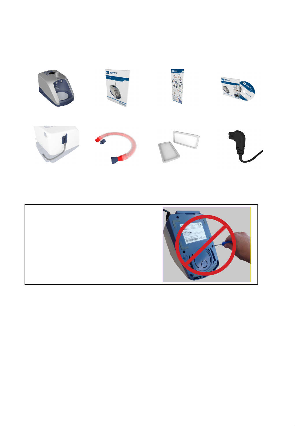
PACKAGE CONTENTS
AIRVO 2 humidifier
(PT101xx)
Oxygen inlet extension kit
(900PT422)
AIRVO 2 User Manual AIRVO 2 Swingtag AIRVO 2 DVD
Disinfection Kit
(900PT600)
WARNING
UNDER NO CIRCUMSTANCES SHOULD THE
AIRVO 2 BE OPENED OR ANY OF THE SIX
FASTENING SCREWS ON THE UNDERNEATH
SIDE OF THE DEVICE BE LOOSENED.
OPENING THE UNIT WILL AFFECT THE
OXYGEN SEALS INSTALLED INSIDE, WHICH
WILL COMPROMISE THE SAFETY OF THE
DEVICE.
Air filter (x2)
(900PT913)
Power cord
(900PT410xx)
4
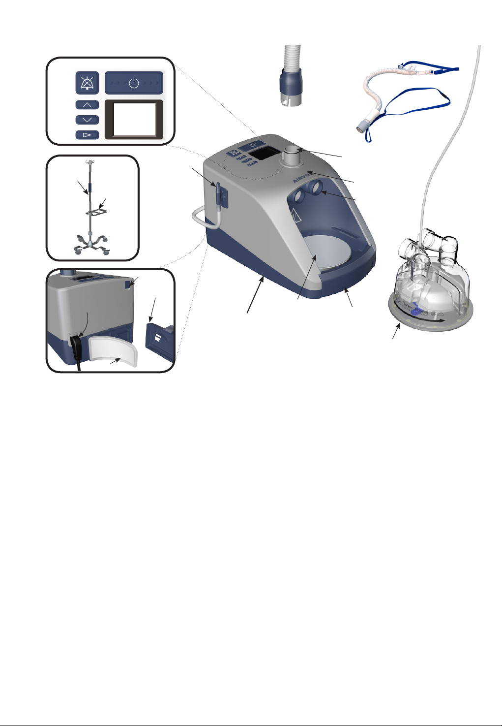
HOSPITAL
STAND
POLE
MOUNTING
TRAY
ON/OFF (STANDBY)
MUTE
UP
DOWN
MODE
AIRVO 2 AND ACCESSORIES
DISPLAY
OXYGEN
INLET PORT
SERIAL PORT
Heated
breathing
tube
Patient
interface
HEATED BREATHING TUBE
CONNECTION PORT
MEASUREMENT POINT OF
DISPLAYED DEW POINT
TEMPERATURE
CHAMBER PORTS
Water chamber
POWER CORD
and
CONNECTOR
AIR FILTER
FILTER COVER
AIRVO 2
(PT101xx)
HEATER
PLATE
FINGER
GUARD
AUTO-FILL WATER
CHAMBER (MR290)
(with adapter fitted)
5
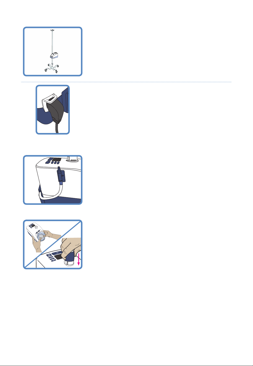
2. SETTING UP AIRVO 2 FOR FIRST USE
1. REMOVE THE AIRVO 2 FROM ITS PACKAGING
Place the AIRVO 2 on the 900PT405 pole mounting tray, on the
900PT421 hospital stand.
2. CONNECT THE POWER CORD
Plug the power cord connector into the socket on the back of the
AIRVO 2.
3. ATTACH THE OXYGEN INLET EXTENSION KIT
Refer to the instruction sheet included with the kit itself.
4. ATTACH WATER CHAMBER AND HEATED BREATHING TUBE
The water chamber and heated breathing tube must be connected to
carry out the following setup and testing procedures.
If you have not been supplied with a reusable HC360 water chamber, you
can use an MR290 chamber instead.
6
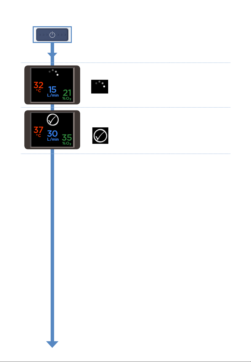
5. SWITCH ON UNIT
Switch on the unit by pressing the On/O button.
6. WARM-UP
The unit will begin to warm up.
“Warm-up” symbol
7. READY FOR USE
The “Ready for use” symbol means that the system is ready for the
patient to use.
“Ready for use” symbol
7
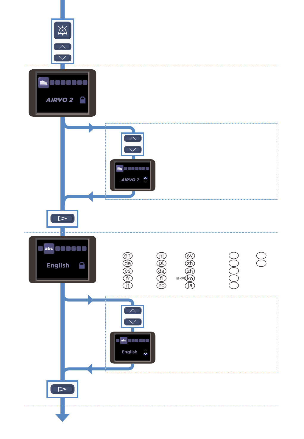
ADVANCED SETTINGS
When you see the “Warm-up” or “Ready for use” symbols, hold a
combination of three buttons (Up, Down and Mute) for 5 seconds, to
view and change advanced settings.
This button combination is for use by clinical engineering / technical
personnel only.
AIRVO 2 / myAIRVO 2 MODE
You can change the unit from “AIRVO” (hospital) mode to “myAIRVO”
(home / long-term care) mode, eg. for patients going home.
Contact Fisher & Paykel Healthcare for a myAIRVO 2 User Manual.
To change the mode:
Hold the Up and Down buttons for 3 seconds to
“unlock” the setting.
Use the Up button to select myAIRVO 2.
Press the Mode button to confirm the change and/or move on to the
next screen. Note that the unit will reset itself if it is switched between
AIRVO 2 and myAIRVO 2 modes.
LANGUAGE
You can set the AIRVO 2 / myAIRVO 2 to one of 22 language settings:
English Nederlands Svenska Polski
Deutsch Português
Español Dansk
Français Suomi Ελληνικά
Italiano Norsk
简体中文
繁体中文
日本語
[simp.]
[trad.]
Русский
עברית
Română
To change the language:
Hold the Up and Down buttons for 3 seconds to
“unlock” the setting.
Use the Up and Down buttons to select the desired
language.
العربية
Türkçe
Press the Mode button to confirm the change and/or move on to the
next screen.
8
95
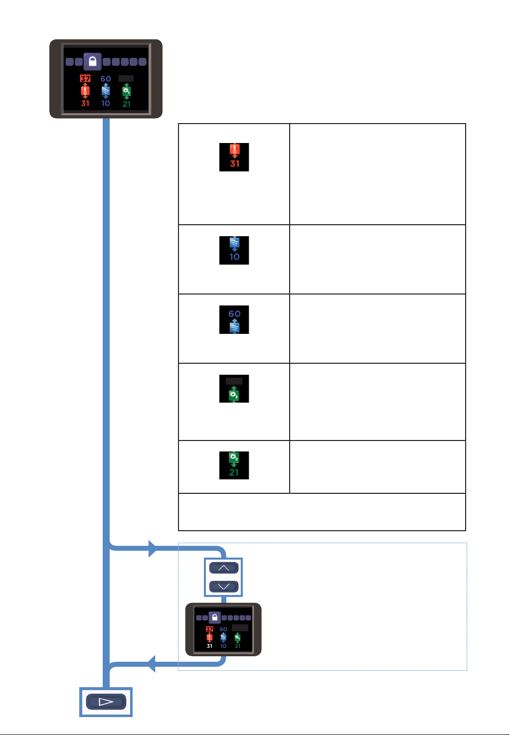
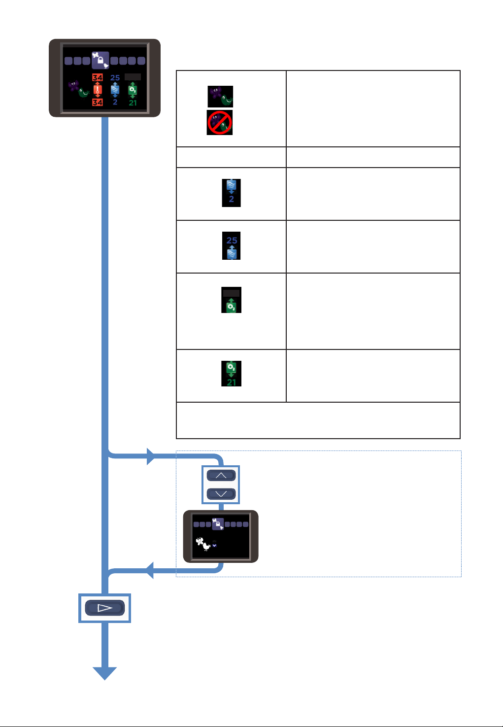
ENVIRONMENT SETTINGS (FOR DEFAULT MODE)
A clinician may change the “Environment Settings”, to customise
individual AIRVOs for dierent environments (eg. intensive care, general
care areas, emergency departments). The “Environment Settings”
chosen will put limits on the “Patient Settings” that the operator can
choose when in normal use.
This screen defines the “Environment Settings” for the AIRVO 2 when in
Default Mode (ie. non-“Junior Mode”).
Minimum dew-point
temperature (°C)
Minimum flow (L/min) The lowest flow that the operator will be able to
Maximum flow (L/min) The highest flow that the operator will be able
Maximum oxygen fraction (%) The highest oxygen fraction that the operator
95
Minimum oxygen fraction (%) The lowest oxygen fraction that the operator
Note that, for Oxygen display, this is a measurement only, not a control setting. The
operator changes the measured oxygen fraction by altering the AIRVO 2 target
flow setting and the flow of oxygen connected to the unit (e.g. from a flowmeter)
— there is no closed-loop control.
The lowest target dew-point temperature that
the operator will be able to select.
Possible Settings: 31, 34, 37 °C
If this is set to 31, the operator can select a target
dew-point temperature between 31 and 37. ie. 31,
34 or 37 (°C).
If the patient is tracheostomised, a clinician may
wish to set this value to 37, so that the operator
can only select a target dew-point temperature
between 37 and 37, ie. only 37 (°C).
Note: The maximum dew-point temperature
setting is always 37 °C in Default Mode.
select.
Possible Settings: 10 to 60 in increments of 5 L/min,
always less than or equal to Maximum Flow setting.
Example: If this is set to 10, the operator will be
able to select flows down to 10 L/min.
If this is set to 25, the operator will be able to
select flows down to 25 L/min.
to select.
Possible Settings: 10 to 60 in increments of 5 L/min,
always greater than or equal to Minimum Flow setting.
Example: If this is set to 60, the operator can
select flows up to 60 L/min.
If this is set to 35, the operator can select flows up
to 35 L/min.
may set the unit to.
Possible settings: 30 — 100% in increments of 5% O2.
The unit will alarm if the measured oxygen
fraction exceeds this value.
Note: Even if this ‘Maximum oxygen fraction‘
setting is set to 100%, any time the measured
oxygen fraction exceeds 95%, the oxygen reading
will pulse red and the device will beep.
may set the unit to.
Possible settings: 21 or 25% O2.
When set to 25% the unit will alarm if the
measured oxygen fraction is below this value. This
allows detection of oxygen being disconnected.
To change the environment settings:
Hold the Up and Down buttons for 3 seconds to
“unlock” the first setting.
95
Use the Up and Down buttons to change the setting,
then press the Mode button to progress to the next
setting.
Press the Mode button to confirm the change and/or move on to the
next screen.
9
95
100
ENVIRONMENT SETTINGS (FOR JUNIOR MODE)
This screen defines the “Environment Settings” for the AIRVO 2 when in
Junior Mode.
Junior Mode Enable/Disable
Enabled
Disabled
Dew-point
temperature (°C)
Minimum flow (L/min) The lowest flow that the operator will be able to
Maximum flow (L/min) The highest flow that the operator will be able
Maximum oxygen fraction (%)
95
Minimum oxygen fraction (%) The lowest oxygen fraction that the operator
Note that, for Oxygen display, this is a measurement only, not a control setting. The
operator changes the measured oxygen fraction by altering the AIRVO 2 target
flow setting and the flow of oxygen connected to the unit (e.g. from a flowmeter)
— there is no closed-loop control.
When this option is enabled (default), the
operator can enter Junior Mode from the Home
Screen, by holding the Mode button for 5
seconds.
When this option is disabled, entering Junior
mode is not possible.
Consider disabling this option if the unit will never
be used on pediatric patients.
The only dew-point setting in Junior Mode is
34 °C.
select.
Possible Settings: 2 to 25 in increments of 1 L/min,
always less than or equal to Maximum Flow setting.
If this is set to 10, the operator will be able to
select flows down to 10 L/min.
to select.
Possible Settings: 2 to 25 in increments of 1 L/min,
always greater than or equal to Minimum Flow setting.
If this is set to 15, the operator can select flows up
to 15 L/min.
The highest oxygen fraction that the operator
may set the unit to.
Possible settings: 30 — 100% in increments of 5% O2.
The unit will alarm if the measured oxygen
fraction exceeds this value.
Note: Even if this ‘Maximum oxygen fraction‘
setting is set to 100%, any time the measured
oxygen fraction exceeds 95%, the oxygen reading
will pulse red and the device will beep.
may set the unit to.
Possible settings: 21 or 25% O2.
When set to 25% the unit will alarm if the
measured oxygen fraction is below this value. This
allows detection of oxygen being disconnected.
To change the environment settings:
Hold the Up and Down buttons for 3 seconds to
“unlock” the first setting.
Use the Up and Down buttons to change the setting,
then press the Mode button to progress to the next
setting.
Press the Mode button to confirm the change and/or move on to the
next screen..
10
Loading…
AIRVO 2 Water Spray Humidifier
AIRVOTM 2
User Manual
SECTION English ………………………………………………………………. A Español ……………………………………………………………… B
Français …………………………………………………………….. C (Chinese Simplified) ……………………….. D
(Chinese Traditional) ………………………. E
English
BEFORE YOU START
· This User Manual is intended for healthcare professionals. · This User
Manual applies to AIRVO 2 units with LOT numbers 130621 and above. · Read this
User Manual including all warnings. Failure to do so may result in injury. In
addition, watch the
AIRVO 2 Video Guide. Keep them both in a safe place for future reference. ·
Before the AIRVO 2 is used for the first time, it must be set up according to
the instructions in the
AIRVO 2 Technical Manual. · The AIRVO 2 must be cleaned and disinfected
between patients according to the instructions in the
Disinfection Kit Manual (900PT600). · For further assistance, please contact
your Fisher & Paykel Healthcare representative.
TABLE OF CONTENTS
1. Overview ………………………………………………………………………………………………………………………………….. A – 2
Intended Use …………………………………………………………………………………………………………………………………………………………. A – 2
Warnings ………………………………………………………………………………………………………………………………………………………………… A – 2
AIRVO 2 and Accessories ……………………………………………………………………………………………………………………………………. A
– 3
2. Setting up AIRVO 2 ………………………………………………………………………………………………………………… A – 4 3.
Using AIRVO 2 ………………………………………………………………………………………………………………………… A – 6
Target dew-point temperature …………………………………………………………………………………………………………………………….
A – 7 Target flow……………………………………………………………………………………………………………………………………………………………….
A – 7 Oxygen ………………………………………………………………………………………………………………………………………………………………….. A
– 8 Alarms ………………………………………………………………………………………………………………………………………………………………….. A –
10
4. Reprocessing …………………………………………………………………………………………………………………………… A – 12
Schedule for changing
accessories…………………………………………………………………………………………………………………….. A – 12 Filter
replacement …………………………………………………………………………………………………………………………………………………. A – 12
Servicing………………………………………………………………………………………………………………………………………………………………….. A –
12
5. Technical Information …………………………………………………………………………………………………………….. A – 13
A 1
1. OVERVIEW
The AIRVO 2 is a humidifier with integrated flow generator that delivers high
flow warmed and humidified respiratory gases to spontaneously breathing
patients through a variety of patient interfaces.
INTENDED USE
The AIRVO 2 is for the treatment of spontaneously breathing patients who would
benefit from receiving high flow warmed and humidified respiratory gases. This
includes patients who have had upper airways bypassed. The flow may be from 2
– 60L/min depending on the patient interface. The AIRVO 2 is for patients in
hospitals and long-term care facilities. USA Federal Law restricts this unit
for sale by or on the order of a physician.
! WARNINGS
· Nasal delivery of respiratory gases generates flow-dependent positive airway
pressure (PAP). This must be taken into account where PAP could have adverse
effects on a patient.
· The unit is not intended for life support. To avoid burns: · The unit should
only be used with interfaces, water chambers and breathing tubes specified in
this user
manual. · Using the breathing tube or interface for longer than the specified
time can result in serious injury
including infection. · Before using oxygen with the unit, read all warnings in
the “Oxygen” section of this manual. · Never operate the unit if:
· the heated breathing tube has been damaged with holes, tears or kinks, · it
is not working properly, · the case screws have ever been loosened. · Do not
block the flow of the air through the unit and breathing tube. · The unit
should be located in a position where ventilation around the unit is not
restricted. · Never block the air openings of the unit or place it on a soft
surface such as a bed or couch/sofa, where the filter area may be blocked.
Keep the air openings free of lint, hair etc. To avoid electric shock: · Do
not store or use the unit where it can fall or be pulled into water. If water
has entered the unit enclosure, disconnect the power cord and discontinue use.
· Never operate the unit if: · it has been dropped or damaged, · it has a
damaged power cord or plug, · it has been dropped into water. · Avoid
unnecessary removal of the power cord from the rear of the device. If removal
is necessary, hold the connector during removal. Avoid pulling on the power
cord. · Return the unit to an authorized service center for examination and
repair, except as outlined in this manual. To avoid choking, or inhalation of
a foreign object: · Ensure an air filter is fitted when operating your unit. ·
Never drop or insert any object into any opening or tube. Miscellaneous: · Do
not use the unit when the room temperature exceeds 30°C (86°F) or is below
10°C (50°F) as the unit may switch off. Humidity output will be compromised
below 18°C (64°F) and above 28°C (82°F). · The unit is not suitable for use in
the presence of a flammable, anesthetic mixture with air or oxygen or nitrous
oxide.
A 2
English
AIRVO 2 AND ACCESSORIES
AUDIO PAUSE ON/OFF (STANDBY)
UP DOWN MODE
DISPLAY
HOSPITAL STAND
POLE MOUNTING
TRAY
OXYGEN INLET PORT
Patient interface
Heated breathing
tube
HEATED BREATHING TUBE CONNECTION PORT MEASUREMENT POINT OF DISPLAYED DEW POINT
TEMPERATURE
CHAMBER PORTS
Water chamber
POWER CORD and
CONNECTOR
SERIAL PORT FILTER COVER
AIR FILTER
AIRVO 2
(PT101AZ/ PT101UK/ PT101US)
HEATER PLATE
FINGER GUARD
AUTO-FILL WATER CHAMBER (MR290) (with adapter fitted)
Tube & chamber kits and patient interfaces
Tube & chamber kit
900PT531
Heated breathing tube, MR290 auto-fill chamber and adapter (10-Pack)
à
OPT316 OPT318
Interfaces
Nasal Cannula – Infant (20-Pack) Nasal Cannula – Pediatric (20-Pack)
900PT501
Heated breathing tube, MR290 auto-fill chamber and adapter (10-Pack)
OPT842 OPT844 à OPT846 OPT870 RT013
Nasal Cannula – Small (20-Pack) Nasal Cannula – Medium (20-Pack) Nasal Cannula
– Large (20-Pack) Tracheostomy Direct Connection (20-Pack) Mask Interface
Adapter – 22mm (20-Pack)
900PT600 900PT601 900PT602 900PT603
Cleaning and Disinfection
Disinfection Kit Disinfection Filter (2-Pack) Cleaning Sponge-Stick (20-Pack)
Clean Storage Cover (20-Pack)
900PT405 900PT421 900PT422 900PT912 900PT913 OPT012
OPT014
Miscellaneous
Pole mounting tray Hospital stand Oxygen inlet extension kit Filter holder Air
filter (2-Pack) Wigglepads (OPT316/OPT318) (20-pack) Oxygen Tubing (Optiflow
Junior)
A 3
2. SETTING UP AIRVO 2
1. BEFORE YOU BEGIN The AIRVO 2 should be fixed on a pole mounting tray
(900PT405) below patient head height. Open the packaging of the tube & chamber
kit (heated breathing tube, MR290 auto-fill chamber and adapter).
2. INSTALL WATER CHAMBER Remove the blue port caps from the chamber by
pulling the tear tab upwards then remove the bracket holding the water supply
tube. Fit the supplied adapter over the two vertical ports on the chamber and
push on fully then clip the water supply tube into position.
Fit the water chamber to the unit by pressing down the finger guard and
sliding the chamber on, carefully aligning with the blue chamber port ends.
Push the chamber on firmly until the finger guard clicks into place.
WARNINGS
To avoid burns: · Do not start the unit without the water chamber in place. ·
The water in the chamber becomes hot during use. Exercise caution when
removing and emptying the chamber. · Do not touch the heater plate, water
chamber or chamber base during use. To avoid electric shock: · When handling
the unit with the water chamber in place, avoid tilting the
machine to prevent any chance of water entering the unit enclosure. · Empty
all the water from the water chamber before transporting the unit.
CAUTIONS
To ensure optimal therapy (MR290 only): · Do not use the auto-fill MR290
chamber if it has been dropped, or been run dry
and the “water out” alarm has been activated.
3. CONNECT WATER BAG
H2O
Attach the sterile water bag to the hanging bracket 20cm (8″) above the
unit, and push the bag spike into the fitting at the bottom of the bag.
Open the vent cap on the side of the bag spike. The chamber will now
automatically fill to the required level and maintain that level until the
water bag is empty.
To ensure continual humidification, always ensure that the water chamber
and/or water bag are not allowed to run out of water.
Check that water flows into the chamber and is maintained below the fill line.
If the water level rises above the fill line, replace the chamber immediately.
MR290: Flow setting vs usage time (2-litre sterile water bag) L/min 2 5 10 15
20 25 30 35 40 45 50 55 60
hrs 379 152 76 51 38 30 25 22 19 17 15 14 13
A 4
English
4. INSTALL HEATED BREATHING TUBE
One end of the heated breathing tube has a blue plastic sleeve. Lift the
sleeve and slide the connector onto the unit. Push the sleeve down to lock.
WARNINGS
To avoid burns: · Do not modify the breathing tube or interface in any way. ·
Do not allow the breathing tube to remain in direct contact with skin for
prolonged periods of time. · Adding heat, above ambient levels, to any part of
the breathing tube or interface
e.g. covering with a blanket, or heating it in an incubator or overhead heater
for a neonate, could result in serious injury. · Do not use an insulating
sleeve or any similar accessories which are not recommended by Fisher & Paykel
Healthcare.
CAUTIONS
· Position the heated breathing tube away from any electrical monitoring leads
(EEG, ECG/EKG, EMG, etc), to minimize any possible interference with the
monitored signal.
5. SELECT PATIENT INTERFACE
The AIRVO 2 can be used with a variety of patient interfaces. Read the
separate user instructions for the patient interface that will be used,
including all warnings.
Nasal cannula
Tracheostomy interface
Mask interface adapter
OPT842 OPT844 OPT846
2
OPT316, OPT318 (Refer to “Using AIRVO 2” –
“Junior Mode”)
OPT870
RT013 (with mask)
Note that the RT013 Mask Interface Adapter is designed to be used with vented
masks only. Do not use sealed masks.
The following table shows the target dew-point temperature settings and target
flow settings able to be used with these interfaces.
2 2
10 10 10 10 10
Low temperature ambient conditions may prevent the unit from reaching a 37 °C
target temperature setting at high target flow settings. In these cases,
consider decreasing the target flow setting.
WARNINGS
To avoid burns: · Do not modify the breathing tube or interface in any way. ·
Do not use any patient interfaces not listed here.
A 5
3. USING AIRVO 2
1. SWITCH ON UNIT Plug the unit’s power cord into the mains power supply. The
connector at the other end of the power cord should be well secured to the
rear of the unit.
WARNINGS
To avoid electric shock: · Ensure that the unit is dry before plugging into
the power socket.
Switch on the unit by pressing the On/Off button.
Last Disinfection:
16
2. CHECK DISINFECTION STATUS The unit will show you whether it is safe for
use on a new patient.
This AIRVO 2 is safe for use on a new patient.
This AIRVO 2 has not been cleaned and disinfected since last use. This AIRVO 2
is NOT safe for use on a new patient.
3. WARM-UP The unit will begin to warm up. You will see numbers showing the
current output dew-point temperature, flow and oxygen values. These numbers
will pulse until they approach their target settings. This screen is called
the “Summary screen”.
4. JUNIOR MODE If the patient will be using an Optiflow Junior nasal cannula
(OPT316/ OPT318), you must activate Junior Mode. Junior Mode limits the target
settings to: 34 °C and 2 – 25 L/min, in increments of 1 L/min.
To activate Junior Mode:
Hold the Mode button for 5 seconds.
New target settings
New target settings The target settings for dew-point temperature and flow
will be changed automatically. The colorful icons in the corners of the screen
indicate that this unit is in Junior Mode.
To deactivate Junior Mode, follow the same procedure: hold the Mode button for
5 seconds.
A 6
English
5. CONFIGURE TARGET SETTINGS Press the Mode button to view target settings.
These settings are locked by default.
TARGET DEW-POINT TEMPERATURE You can set the AIRVO 2 to three target dew-point
temperature settings: · 37°C (98.6°F) · 34°C (93°F) [if compliance at 37°C is
a problem] · 31°C (88°F) [for face masks only]. You may not have access to all
settings, if: · the unit is in Junior Mode (limited to 34 °C), · the unit was
initially set up with tighter limits. The AIRVO 2 will return to its default
setting (37°C) after every disinfection cycle.
To change the target dew-point temperature setting:
Hold the Up and Down buttons for 3 seconds to “unlock” the setting.
The lock will disappear and be replaced by an arrow showing the minimum and
maximum accessible settings. Press the Up and Down buttons to choose the new
setting.
When you have finished, press the Mode button to ‘lock’ the setting again.
The lock will reappear.
N
A Transport Mode: If Transport Mode has been enabled, you can activate it on
this screen by holding the “Audio pause” button for 5 seconds. The unit will
enter a low-power, low-humidity mode for 20 minutes, designed for use when
transporting patients. For more information, refer to REF 185048130. To
deactivate Transport Mode, follow the same procedure: hold the “Audio pause”
button for 5 seconds.
Press the Mode button to move on to the next screen.
TARGET FLOW You can set the AIRVO 2 to flows between 10 L/min and 60 L/min, in
increments of 1 L/min (10-25 L/min) and 5 L/min (25-60 L/min). You may not
have access to all settings, if: · the unit is in Junior Mode (limited to 2 –
25 L/min,
in increments of 1 L/min), · the unit was initially set up with tighter
limits. The AIRVO 2 will remember its target flow setting when you switch it
off.
To change the target flow setting: Follow the same sequence of steps as above
in “To change the target dew-point temperature setting”.
A 7
Press the Mode button to move on to the next screen.
OXYGEN You can connect supplementary oxygen to the AIRVO 2 (up to 60 L/min).
The AIRVO 2 contains an oxygen analyzer to help you determine the oxygen
fraction you are delivering to the patient. Your unit may have been initially
set up with tighter limits. Use continuous oxygen monitoring on patients who
would desaturate significantly in the event of disruption to their oxygen
supply.
WARNINGS
Before using the AIRVO 2 with oxygen, read all of the following warnings: ·
The use of oxygen requires that special care be taken to reduce the risk of
fire.
Accordingly, for safety it is necessary that all sources of ignition be kept
away from the unit and preferably out of the room in which it is being used.
Oxygen should not be used while smoking or in the presence of an open flame.
The unit should be located in a position where ventilation around the unit is
not restricted. · A spontaneous and violent ignition may occur if oil, grease
or greasy substances come in contact with oxygen under pressure. These
substances must be kept away from all oxygen equipment. · Ensure that the
AIRVO 2 is switched on before connecting oxygen. · Oxygen must only be added
through the special oxygen inlet port on the back of the unit. To ensure that
oxygen enters the unit correctly, the oxygen inlet port must be fitted
properly to the filter holder and the filter holder must be fitted properly to
the unit. The power cord connector should also be well secured. · Do not
connect more than 60L/min O2 to the oxygen inlet port on the back of the unit.
· The oxygen concentration delivered to the patient can be affected by changes
to the flow setting, oxygen setting, patient interface or if the airpath is
obstructed. · When finished, turn off the oxygen source. Remove the output of
the oxygen source from the oxygen inlet port on the back of the unit. The
oxygen flow must be turned off when the unit is not operating, so that oxygen
does not build up inside the device. · The oxygen analyzer within the AIRVO 2
uses ultrasonic measurement technology. It does not require in-field
calibration. It is designed for use with pure oxygen – connecting any other
gases or mixtures of gases will cause it to function incorrectly.
CONNECT OXYGEN Connect the output from the oxygen source to the oxygen inlet
port on the back of the unit. Make sure you push the oxygen tube firmly onto
this connection port.
ADJUST OXYGEN Adjust the level of oxygen from the oxygen source, until the
desired oxygen fraction is displayed onscreen. It may take the reading several
minutes to settle. You can set the oxygen fraction between the maximum and
minimum values displayed above and below the arrow. If the oxygen fraction
exceeds 95%, the oxygen reading will pulse red and the device will beep.
WARNINGS
· Note that if the patient’s peak inspiratory demand exceeds the flow
delivered by the unit, the fraction of oxygen inspired by the patient will be
lower than the value shown onscreen, due to the additional entrainment of
ambient air.
· Check that suitable blood saturation levels are achieved at the prescribed
flow.
Press the Mode button to return to the Summary screen.
A 8
English
6. CONNECT YOUR PATIENT Wait until the “Ready for use” symbol is displayed on
the Summary screen.
“Ready for use” symbol
Connect the patient interface to the heated breathing tube. Monitor the flow
and oxygen values displayed on the Summary screen. Adjust the level of oxygen
from the oxygen source as necessary. When the patient first uses the unit, the
air will feel warm. This is normal. The patient should continue to breathe
normally through the nose and/or mouth, or tracheostomy.
7. DURING USE If the “Ready for use” symbol has been displayed for 1 minute
and no button has been pushed in this time, a screensaver will be launched.
If excess condensate accumulates in the heated breathing tube, drain by
lifting the patient end of the tube, allowing the condensate to run into the
water chamber.
8. AFTER USE Switch off the unit by pressing the On/Off button.
A 9
ALARMS
The AIRVO 2 has visual and auditory alarms to warn you about interruptions to
your patient’s treatment. These alarms are generated by an intelligent alarm
system, which processes information from the sensors and target settings of
the unit and compares this information to pre-programmed limits.
ALARM SIGNALS
Visual alarm signal
Symbols
Meaning
(message)
Alarm condition. Audio paused.
Auditory alarm signal
3 beeps in 3 seconds. Repeated every 5 seconds.
Press this button to mute the auditory alarm for 115 seconds. The auditory
alarm can be reactivated by pressing this button again.
ALARM CONDITIONS
All of the alarms listed below have been assessed as “Medium Priority”. These
priorities have been allocated for an operator’s position within 1 meter of
the device. The unit also uses an internal priorityranking system. If multiple
alarm conditions occur simultaneously, the unit will display the highest-
priority alarm.
The following table lists all of the alarm conditions from highest-priority to
lowest priority, their causes, possible solutions and delays. Alarm conditions
that affect oxygen delivery require an immediate response to assess the
patient’s saturation levels. Alarm conditions that affect humidity delivery
require a prompt response to assess potential drying of mucus and associated
blockages.
Message
Meaning
Fault (E###) Check tube
Check for leaks
Check for blockages
O2 too low O2 too high
The unit has detected an internal fault and has shut itself down. Switch the
unit off and then restart. If the problem persists, note the fault code and
contact your Fisher & Paykel Healthcare representative.
The unit cannot detect the heated breathing tube. Check that the heated
breathing tube is not damaged and that it is plugged in correctly. If the
problem persists, then change the heated breathing tube.
The unit has detected a leak in the system. The most likely cause is that the
water chamber has been removed or has not been pushed into place correctly.
Check that the heated breathing tube is not damaged and that it is plugged in
correctly. Check that the nasal interface is fitted. Check that the filter is
fitted.
The unit has detected a blockage in the system. Check the heated breathing
tube or patient interface for blockage. Check the air filter and filter holder
for blockage. Check whether the unit should be in Junior Mode. If the patient
will be using an Optiflow Junior nasal cannula (OPT316/OPT318), you must
activate Junior Mode.
The measured oxygen level has fallen below the allowed limit. Check that the
oxygen source is still correctly connected. Adjust the level of oxygen from
the oxygen source as necessary.
The measured oxygen level has exceeded the allowed limit. Adjust the level of
oxygen from the oxygen source as necessary.
Affects delivery of:
Delays
Oxygen, humidity.
< 5 seconds
Oxygen, humidity.
< 5 seconds
Oxygen, humidity.
< 5 seconds
Oxygen, humidity.
< 10 seconds
Oxygen < 20 seconds Oxygen < 20 seconds
A 10
English
(continued)
Message
Meaning
Affects delivery of:
Cannot reach target
flow
The unit cannot reach the target flow setting.
Check the heated breathing tube or patient interface for blockage. Check
whether the target flow setting is too high for the patient interface being
used (refer to “Setting up AIRVO 2” – “Select Patient Interface”). The unit
will choose appropriate new target settings. You will be prompted for
acknowledgement.
Oxygen
WARNINGS
· The oxygen concentration delivered to the patient can be affected by changes
to the flow setting. Adjust the level of oxygen from the oxygen source as
necessary.
Check water
The chamber has run out of water.
When a chamber runs dry, the chamber float may be damaged. Replace the chamber
and water bag. [Twenty seconds after the chamber is removed, the “Check for
leaks” alarm is activated (see above). When the chamber is replaced, the unit
enters Warm-up Mode and resumes normal operation.] To ensure continual
humidification, always ensure that the water chamber and/or water bag are not
allowed to run out of water.
Humidity
Cannot reach target temperature
The unit cannot reach the target temperature setting.
You will be prompted for acknowledgement.
The most likely cause for this is that the unit is operating at a high flow
rate in low ambient conditions. Consider decreasing the target flow setting.
WARNINGS
Humidity
· The oxygen concentration delivered to the patient can be affected by changes
to the flow setting. Adjust the level of oxygen from the oxygen
source as necessary.
Check operating conditions
The unit has detected that it is operating in unsuitable ambient conditions.
Do not use the device when the ambient temperature is less than 10°C. Do not
use the device when the ambient temperature is greater than 30°C. This alarm
may be caused by a sudden change in ambient conditions (eg. storing the unit
in a cold place then using it in a warm place). Leave the unit running for 30
minutes. Switch the unit off and then restart.
Humidity
[Power out] The unit has been disconnected from the mains power supply. No
visual alarm. The auditory alarm will sound for 120 seconds.
Oxygen, humidity.
Delays
10 +/- 1 minutes
Flows above 20 L/min:
< 20 minutes Flows of and below 20 L/min:
< 40 minutes
30 +/- 3 minutes
60 +/- 6 seconds
< 5 seconds
ALARM LIMITS
Most alarm limits are pre-programmed. The exceptions are listed below. These
alarm limits may be changed to other values by authorized personnel. Changes
will be preserved during or after any power loss.
Alarm condition
O2 too low O2 too high
Factory-set alarm limit
21% O2 95% O2
Possible preset values
21 25% O2 30 100% O2
WARNINGS
· A hazard can exist if different alarm presets are used on different units
within any single area, eg. an intensive care unit. · Alarm limits set to
extreme values can render the alarm system useless.
CHECKING ALARM SYSTEM FUNCTIONALITY
The functionality of the alarm system can be checked at any time when the unit
is turned on.
Remove the heated breathing tube. You should see the “Check tube” visual alarm
signal and hear the auditory alarm signal. If either alarm signal is absent,
do not use the unit. Contact your Fisher & Paykel Healthcare representative.
AUDITORY INFORMATION SIGNALS In addition to auditory alarm signals, auditory
information signals are provided. These are described below.
Melody Ascending sequence of 5 tones Ascending sequence of 3 tones
Single tone every 5 seconds
Meaning The “Ready for use” symbol has appeared
Activation/deactivation of Junior Mode Measured oxygen level > 95%, OR,
Measured oxygen level > 32% at turn-off
A 11
4. REPROCESSING
The AIRVO 2 must be cleaned and disinfected between patients according to the
instructions in the Disinfection Kit Manual (900PT600).
This should take place as soon as possible after use. The unit utilizes warmed
water and can pose a risk of bacterial colonization and patient infection if
cleaning, disinfection and replacement procedures are not followed.
Standard aseptic techniques to minimize contamination should be followed when
handling the unit and accessories. This includes proper hand-washing, avoiding
hand contact with connection ports, safe disposal of the used consumables and
suitable storage of the unit after cleaning and disinfection.
SCHEDULE FOR CHANGING ACCESSORIES
The accessories for the unit must be changed frequently to avoid the risk of
infection. Parts should be replaced immediately if they are damaged or
discolored; otherwise they must be replaced within the periods shown in the
following table.
Maximum period of use
Part number and description
1 week (single-patient
use)
All patient interfaces
OPT316 Nasal Cannula – Infant
OPT318 Nasal Cannula – Pediatric
OPT842 Nasal Cannula – Small
OPT844 Nasal Cannula – Medium
OPT846 Nasal Cannula – Large
OPT870 Tracheostomy Interface
RT013
Mask Interface Adapter – 22mm
2 weeks (single-patient
use)
All tube & chamber kits 900PT501 Heated breathing tube, MR290 auto-fill
chamber and adapter
900PT531 Heated breathing tube, MR290 auto-fill chamber and adapter (for use
with OPT316/318 only)
3 months or
1000 hours
900PT913 Air filter (or more often if significantly discolored)
FILTER REPLACEMENT
Air filter change due
If the unit tells you that a filter change is due:
1. Take the filter holder from the back of the unit and remove the filter. 2.
Replace the old filter with a new one.
3. Reattach the filter holder to the unit (clip the bottom of the filter
holder in first, then rotate it upwards until the top clips into place).
4. Press the Mode button to move on to the next screen.
SERVICING This device contains no serviceable parts.
A 12
English
5. TECHNICAL INFORMATION
SYMBOL DEFINITIONS
Caution
Type BF
Hot Surfaces Applied Part
ATTENTION Consult
accompanying documents
Do not throw away
PRODUCT SPECIFICATIONS
Drip Proof
Alternating Current
Class ll Double Insulated
Power On/Off (Standby)
93/42/EEC Class IIa
Dimensions
295 mm x 170 mm x 175 mm (11.6″ x 6.7″ x 6.9″)
Weight
2.2 kg (4.8 lb) unit only, 3.4 kg (7.5 lb) packaged in bag incl. accessories
Supply frequency
50-60 Hz
Supply voltage/current 100-115 V 2.2 A (2.4 A max) 220-240 V 1.8 A (2.0 A max)
Sound pressure level Alarms exceed 45dbA @ 1 m
Auditory alarm pause 115 seconds
Serial port
The serial port is used for downloading product data, using F&P InfosmartTM
software.
Humidity
33 mg/L at 37 °C target >10 mg/L at 34 °C target >10 mg/L at 31 °C target
Maximum temperature of delivered gas
43 °C (109 °F)
Maximum flow range 10-60 L/min (default)
Maximum flow range (Junior Mode)
2-25 L/min
Maximum oxygen input 60 L/min
Warm-up time
10 minutes to 31 °C (88 °F), 30 minutes to 37 °C (98.6 °F) using a MR290
chamber with flow rate of 35 L/min and starting temperature 23 ± 2 °C (73 ± 3
°F)
Oxygen analyzer accuracy
< ± (2.5% + 2.5% of gas level) (within the range 25-95% O2)
Operating conditions: 18-28 °C (64-82 °F), 30-70% RH
Designed to conform to the requirements of:
IEC 60601-1 UL 60601-1 CSA C22.2/No. 601.1 AS 3200.1.0 EN 60601-1
The unit complies with the electromagnetic compatibility requirements of IEC
60601-1-2. In certain circumstances, the unit may affect or be affected by
nearby equipment due to the effects of electromagnetic interference. If this
should happen, try moving the unit or the location of the unit causing
interference, or alternatively consult your healthcare provider.
Accessory equipment connected to the serial port of the device must be
certified to either IEC 60601-1 or IEC 60950-1. Furthermore all configurations
shall comply with the system standard IEC 60601-1-1. Anyone who connects
additional equipment to the signal input part or signal output part configures
a medical system and is therefore responsible for ensuring that the system
complies with the requirements of the system standard IEC 60601-1-1. If in
doubt, consult the technical services department or your local representative.
OPERATING CONDITIONS
Ambient temperature Humidity Altitude Mode of operation
18 – 28 °C (64 – 82 °F) 10 – 95% RH 0 – 2000 m (6000 ft) Continuous operation
STORAGE AND TRANSPORT CONDITIONS
The unit should be stored and transported in environmental conditions of -10
°C to 60 °C (14 °F to 140 °F), 10 to 95% RH, non-condensing.
DISPOSAL INSTRUCTIONS
Unit Disposal Instructions This unit contains electronics. Please do not
discard with regular waste. Return to Fisher & Paykel Healthcare or dispose
according to local guidelines for disposing of electronics. Dispose according
to Waste Electrical and Electronic Equipment (WEEE) directive in European
Union.
Consumables Disposal Instructions Place the interface, breathing tube and
chamber in a waste bag at the end of use. Hospitals should discard according
to their standard method for disposing of contaminated product.
A 13
For more information please contact your local Fisher & Paykel Healthcare
representative
Manufacturer Fisher & Paykel Healthcare Ltd 15 Maurice Paykel Place East
Tamaki, Auckland 2013
PO Box 14 348, Panmure Auckland 1741 New Zealand
Tel: +64 9 574 0100 Fax: +64 9 574 0158 Email: info@fphcare.com Web:
www.fphcare.com
Australia Fisher & Paykel Healthcare Pty Limited 36-40 New Street, PO Box 167
Ringwood, Melbourne Victoria 3134, Australia
Tel: +61 3 9879 5022 Fax: +61 3 9879 5232
Austria Tel: 0800 29 31 23 Fax: 0800 29 31 22
Benelux Tel: +31 40 216 3555 Fax: +31 40 216 3554
China Tel: +86 20 3205 3486 Fax: +86 20 3205 2132
France Tel: +33 1 6446 5201 Fax: +33 1 6446 5221
Spain Tel: +34 902 013 346 Fax: +34 902 013 379
Sweden Tel: +46 8 564 76 680 Fax: +46 8 36 63 10
Switzerland Tel: 0800 83 47 63 Fax: 0800 83 47 54
Taiwan Tel: +886 2 8751 1739 Fax: +886 2 8751 5625
Turkey Fisher Paykel Salik Ürünleri Ticaret Limited irketi, Alinteri Bulvari
1161/1 Sokak No. 12-14, P.O. Box 06371 Ostim, Ankara, Turkey
Tel: +90 312 354 34 12 Fax: +90 312 354 31 01
Germany Tel: +49 7181 98599 0 Fax: +49 7181 98599 66
India Tel: +91 80 4284 4000 Fax: +91 80 4123 6044
UK Fisher & Paykel Healthcare Ltd Unit 16, Cordwallis Park Clivemont Road,
Maidenhead
Berkshire SL6 7BU, UK
Tel: +44 1628 626 136 Fax: +44 1628 626 146
Irish Republic Tel: 1800 409 011
Italy Tel: +39 06 7839 2939 Fax: +39 06 7814 7709
USA/Canada Tel: +1 800 446 3908 or +1 949 453 4000 Fax: +1 949 453 4001
REF 185045495 REV C 2013-Sep © 2013 Fisher & Paykel Healthcare Limited
0123
www.fphcare.com
Read User Manual Online (PDF format)
Read User Manual Online (PDF format) >>
Download This Manual (PDF format)
Download this manual >>
Bookreader Item Preview
1,074
Views
DOWNLOAD OPTIONS
Temporarily Unavailable
EPUB
Uploaded by
Sketch the Cow
on