
anua
7
Q
Q
TEL 13942296513 QQ 376315150 892498299
3
CDSTEREO SYSTEM
6
3
1
5
1
5
0
NSX-A959
NSX-F959
8
9
2
4
awa
SERVICE
9
8
2
9
9
TEL 13942296513 QQ 376315150 892498299
TEL
● If requiring information about the CD mechanism, see Service Manual of 6ZG- 1,
S/M Code No. 09-984-249-90T.
13942296513
SYSTEM
NSX-A959
(TYPE : U)
NSX-F959
(TYPE : LH)
CD — CASSEIVER
CX-NA959
CX-NF959
Q
Q
3
7
1
3
6
SPEAKER
SX-WNA958
SX-WNF959
5
1
5
0
8
9
2
4
9
8
2
9
9
w
w
w
.
xia
o
y
u
1
6
3
.
c
o
m

TABLE OF CONTENTS
PROTECTION OF EYES FROM LASER BEAM DURING SERVICING …………………….. …… ………………… …3
PRECAUTION TO REPLACE OPTICAL BLOCK …………. . …… ………………… …… ………………… ……. . ………………3
SPECIFICATIONS ………………… . …… ……………………… ………………………. ……. ………………… …… ……………………… 4
Q
Q
NOTE ON BEFORE STARTING REPAIR …………….. …… ……………………………………………….. …… . ………………….. 5
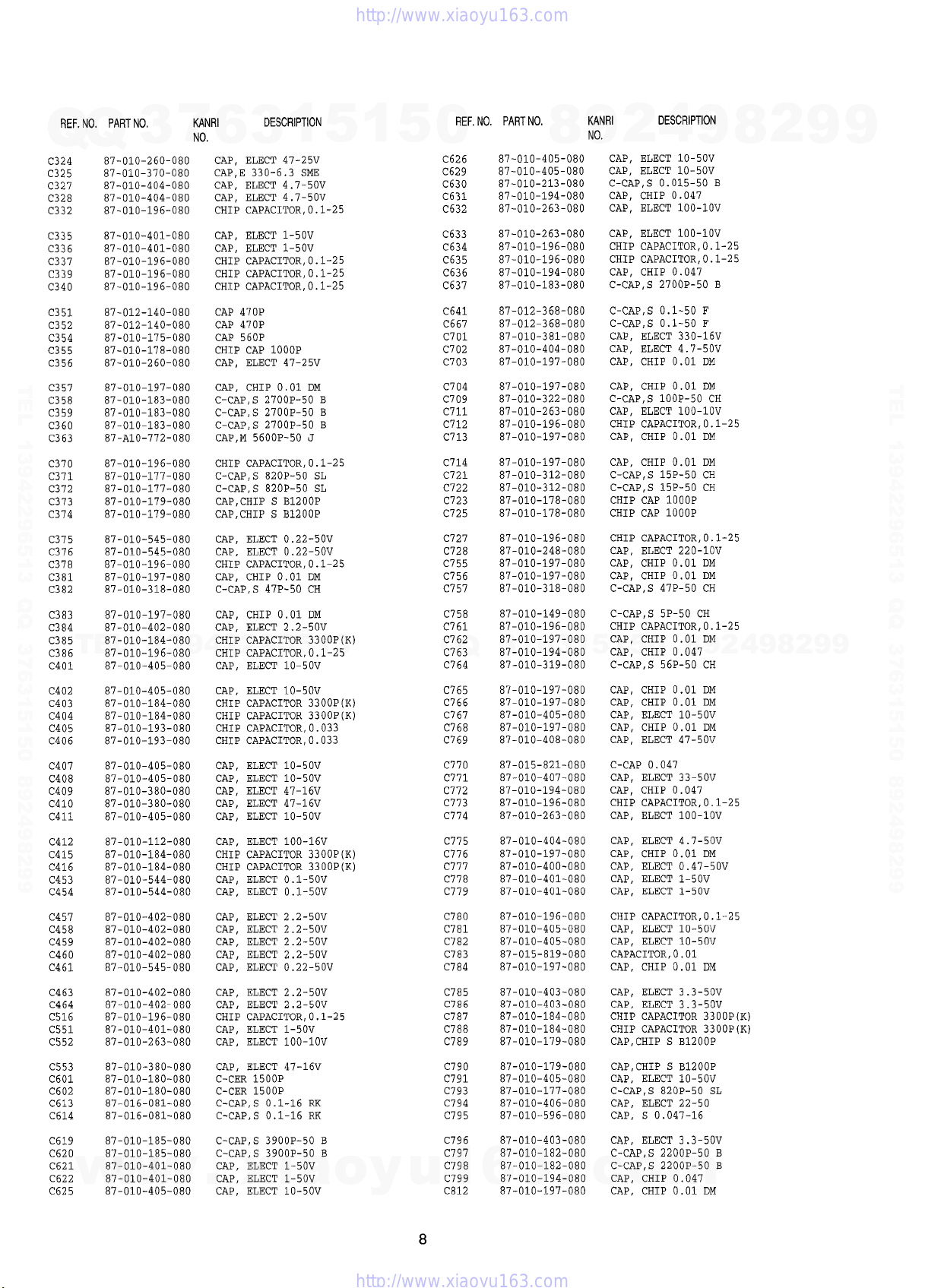
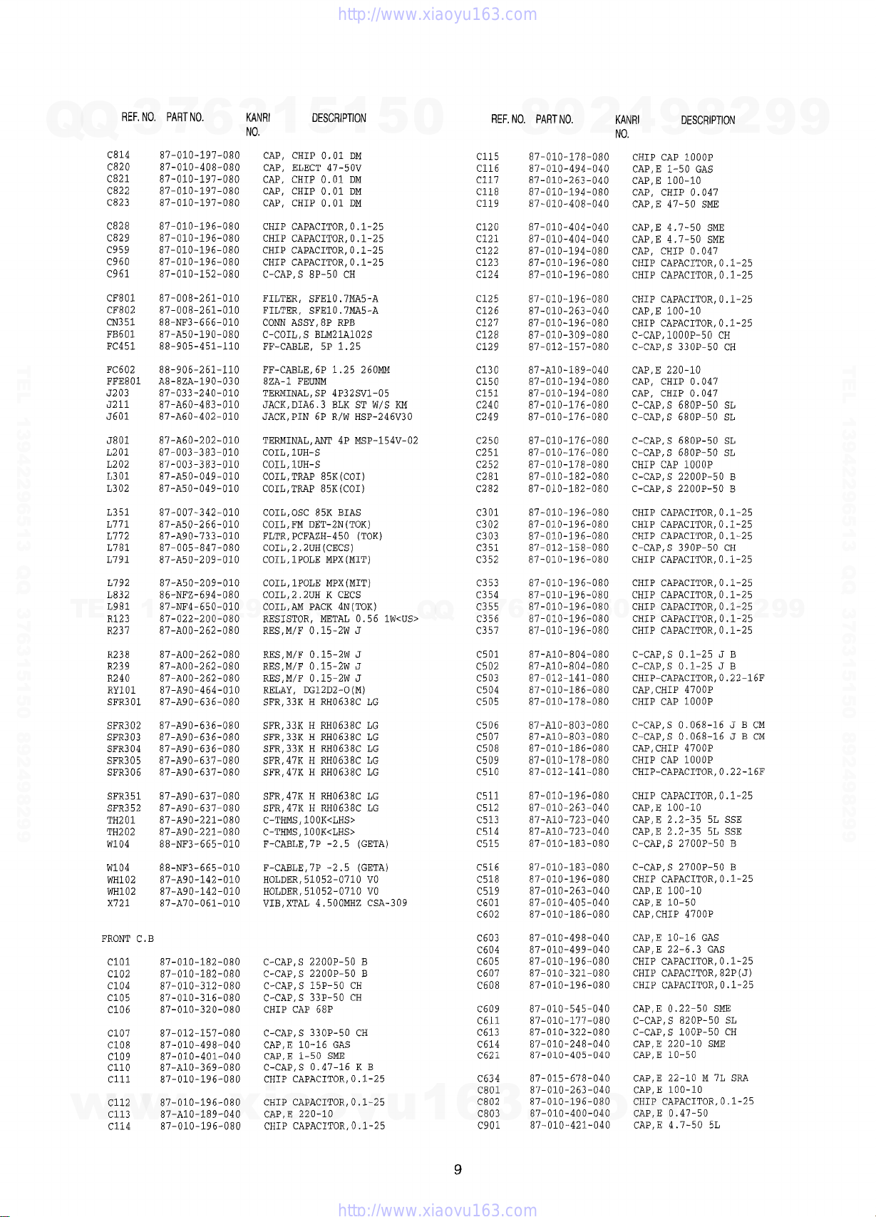
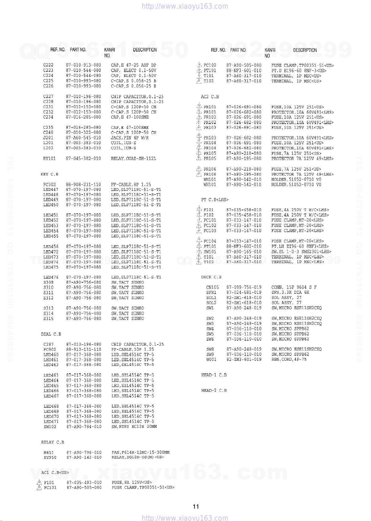
ELECTRICAL MAIN PARTS LIST …………… ……. ……………………… . ……………………… …… ………………… ……. ……. 7
TRANSISTOR ILLUSTRATION
BLOCK DIAGRAM- 1 (MAIN/FRONT) ………….. …… ………………… . …… ………………………. …… ……………………. 13
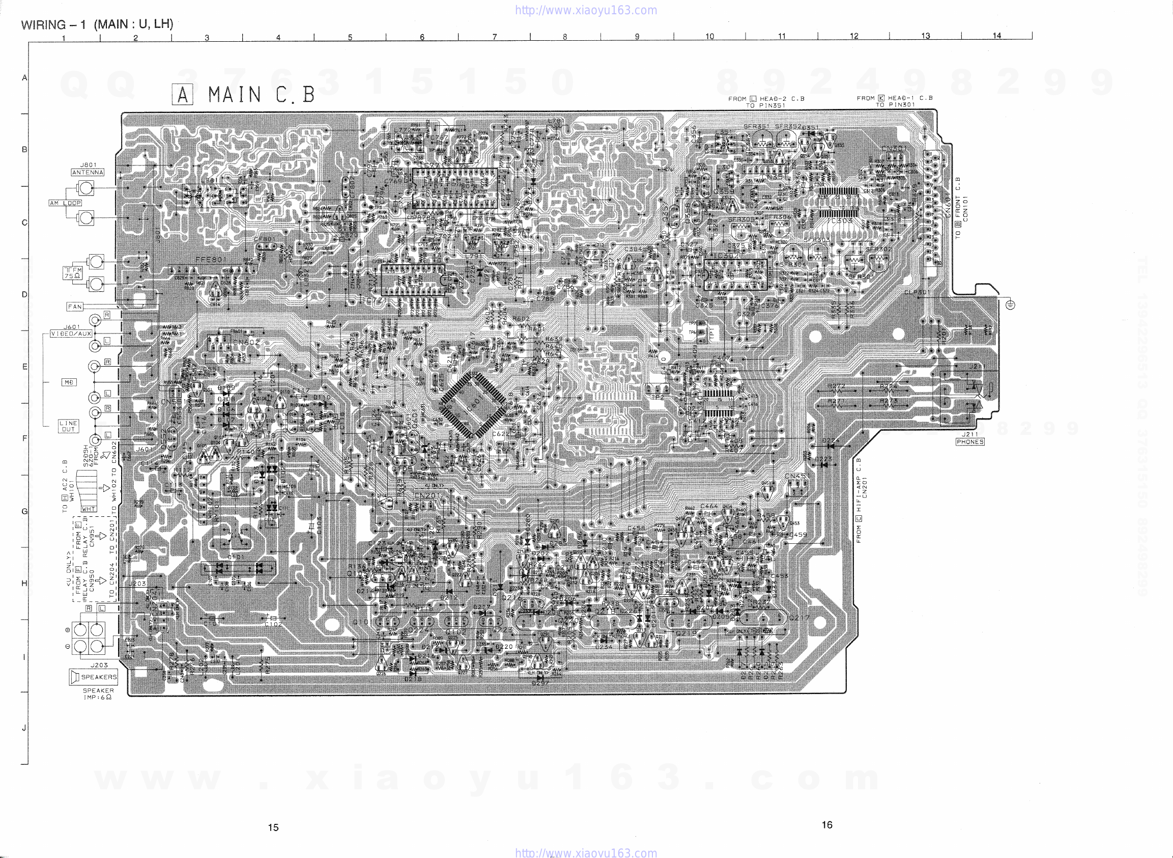
WIRING -1 (MAIN : U. LH) ……………… ………………… ……. ……………………… . …… ………………… …… …………………. 15
SCHEMATIC DIAGRAM -1 (MAIN: U) …. …… ………………… …… . ……………………………. ………………… ……. …….. 17
SCHEMATIC DIAGRAM -2 (MAIN : LH) …………………. …… ………………………. ……. ………………… …… . …………… 20
SCHEMATIC DIAGRAM –3 (TUNER) ……… . …… …….s.s……… ……………………… ……. ………………………. …… ……. 23
IC BLOCK DIAGRAM-1 ………………….. ……………………………. ………………… . …………………………………. ………….. 25
SCHEMATIC DIAGRAM –4 (FRONT) ……… ……. ………………… …… . ……………………… …… . ………………………….. 26
WIRING-2 (FRONT) .. ……………….. ……. ……………………… ……………………… . …… ………….. …………………………… 29
SCHEMATIC DIAGRAM -5 (HIFI-AMP) …….. ……. ………………… …… ………………… ……. ……………………………. .. 31
WIRING -3 (HIFI-AMP) ………………… …… ………………… ……. …………………………………s…………….. ……. ………….. 33
TEL 13942296513 QQ 376315150 892498299
WIRING –4 (JOG/RELAY/KEY) ……. ……………………… ……. ………………… …… …………………………….. …………….. 35
SCHEMATIC DIAGRAM -6 (RELAY)
WIRING -5 (DECK) ………… ……………………… . …… ………………… …………………………… . …… . …………………………. 38
WIRING -6 (AC/PT) ………….. ………………………. ……………………… ……. ………………… …… …………………………….. 39
ADJUSTMENT– 1 <TUNER/ DECK> ……………… . …… ………………… …… . ……………….. ……. ………………………. … 40
PRACTICAL SERVICE FIGURE ……….. ……. ……………….. ……. ……. …………………………s…………………….. ……. … 42
IC DESCRIPTION ……………… ……. ………………………. …… ………………… ……………………………. ………………………. 43
FL GRID ASSIGNMENT& ANODE CONNECTION ……… …… . ………………..s…….. . …… ………………… ……. ……. …. 45
MECHANICAL EXPLODED VIEW 1 / 1 …………. ……………………… …… . ……………………… . …… ………………… ….. 47
MECHANICAL PARTS LIST 1 / 1 …… ……. ……………………… . …… ………………… …… ………………… ……. ……. ……. 49
TAPE MECHANISM EXPLODED VIEW 1 / 1 ……………….. …… . ……………….. ……. ………………………. …… . ……… 50
TAPE MECHANISM PARTS LIST 1 / 1 ….. ……. ……………….. ……. ……………………………. ………………………. …… 52
SPRING APPLICATION POSITION ……. . …… ………………… …… . ……………………… …… . ………………… …… . ………. 53
IC BLOCK DIAGRAM .2 ………………………… ……. ……………….. . …… ……………………… ………………………………….. 54
TEL
SPEAKER DISASSEMBLY instruction ……………………. …… ………………… …… ………………………. . …… ……….. 58
SPEAKER PARTS LIST …… ………………………. …… ………………… …… . ……………….. ……. ………………………………… 59
ACCESSORIES / PACKAGE LIST …….. …… ………………… ……………………………. ……. ………………… …… . …………. 60
REFERENCE NAME LIST ……. ……. ………………… …… ………………… …… ………………… ……. ………………………….. 61
7
3
13942296513
6
1
3
…………….. …… ………………………. ……………………………. ………………………. …… … 12
5
1
5
0
………………….. ……………………..n……. ……………………………. . ……………… 37
6
7
3
Q
Q
8
3
1
9
5
1
2
5
4
0
8
9
9
8
2
4
2
9
8
9
2
9
9
TEL 13942296513 QQ 376315150 892498299
9
w
w
w
.
xia
o
y
u
1
6
2
3
.
c
o
m
This set employs laser. Therefore, be sure to follow carefully the
instructions below when servicing.
7
3
Q
TEL 13942296513 QQ 376315150 892498299
WARNING!!
Q
WHEN SERVICING, DO NOT APPROACH THE LASER
EXIT WITH THE
NECESSARY TO CONFIRM LASER BEAM EMISSION.
BE SURE TO OBSERVE FROM A DISTANCE OF MORE
THAN 30cm FROM THE SURFACE OF THE OBJECTIVE LENS ON THE OPTICAL PICK-UP BLOCK.
*
A
VAROITUS!
Laiteen Kayttaminen muulla kuin tassa kayttoohjeessa
mainitulla tavalla saataa altistaa kayt-tajan
turvallisuusluokan 1 ylittavalle nakymattomalle
Iasersateilylle.
VARNING!
Om apparaten anvands PA annat satt an vad som
specificeras i denna bruksanvising, kan anvandaren
utsattas for osynling IaserstrAlning, som overskrider
gransen for laserklass 1.
6
EYE TOO CLOSELY. IN CASE IT IS
■ Caution: Invisible laser radiation when
open and interlocks defeated avoid
exposure to beam.
■ Advarsel: Usynlig laserst2ding ved ~bning,
n~rsikkerhedsafbrydere er ude af funktion.
Undg& udsa?ttelse for str#ding.
3
1
5
1
5
0
CAUTION
Use of controls or adjustments or performance of proce-
dures other than those specified herin may result in
hazardous radiation exposure.
ATTENTION
L’utillisation de commandes, reglages ou procedures
autres que ceux specifies peut entrakrer une dangereuse
exposition aux radiations.
ADVARSEL
Usynlig IaserstAling ved abning, n~rsikkerhedsaf brydereer
ude af funktion. Undg5 udsattelse for str?ding.
This Compact Disc player is classified as a CLASS 1
LASER product.
The CLASS 1 LASER PRODUCT label is located on the
rear exterior,
4
2
9
8
CLASS 1
KLASSE 1
LUOKAN 1
KLASS 1 LASER APPARAT
9
LASER PRODUCT
LASER PRODUKT
LASER LAITE
8
2
9
I
9
TEL 13942296513 QQ 376315150 892498299
TEL
13942296513
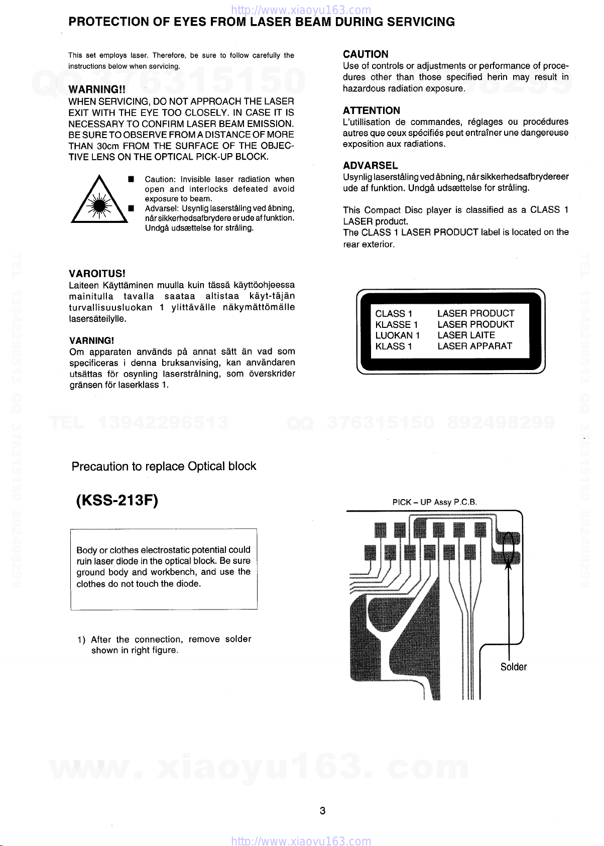
Precaution to replace Optical block
(KSS-213F)
Body or clothes electrostatic potential could
ruin laser diode in the optical block. Be sure
ground body and workbench, and use the
clothes do not touch the diode.
1) After the connection, remove solder
shown in right figure.
Q
Q
3
7
6
1
5
1
3
PICK — UP k.s)I P.C.B.
5
0
8
9
2
4
9
8
2
9
9
w
w
w
.
xia
o
y
u
1
6
3
.
c
o
m

SPECIFICATIONS
cFM Tuner section>
Tuning range
Usable sensitivity(lHF)
Antenna terminals
Q
Q
cMW Tuner section>
Tuning range
Usable sensitivity
Antenna
cAmplifier section>
Mid-high frequency amplifier
Power output
Total harmonic distortion
Low-high frequency amplifier
TEL 13942296513 QQ 376315150 892498299
Inputs
outputs
<Cassette deck section>
Track format
Frequency response
Signal-to-noise ratio
Recording system
Heads
<Compact disc player section>
Laser
D-A converter
Signal-to-noise ratio
Harmonic distortion
Wow and flutter
—……..
— …. ..
rower outpuI
Total harmonic distortion
TEL
3
13942296513
87.5 MHz to 108 MHz
13.2 dBf
75 ohms (unbalanced)
7
6
531 kHz to 1602 kHz (9 kHz step)
530 kHz to 1710 kHz (1 O kHz step)
350 uV/m
Loop antenna
U:30W+30W (200 Hz-20 kHz,
T.H.D. less than 1%, 6 ohms)
LH :40 W + 40 W (1 kHz, T. H. D.10%,
6 ohms)
0.3% (6 W, 1 kHz, 6 ohms, DIN
AUDIO)
U:130W+ 130 W(20HZ-200 HZ,
T.H.D. less than 17.; 6 ohms)
LH :170 W + 170 W (75
10%, 6 ohms)
0.3% (13.5 W, 75 Hz, 6 ohms, DIN
AUDIO)
VI DEO/AUX: 210 mV(adjustable)
MD :21 OmV (adjustable)
MlCl, MIC2 : 1.4mV (10 kohrms)
LINE OUT: 200mV
SPEAKERS: accept speakers of
6 ohms or more
SURROUND SPEAKERS:
accept speakers of 8 ohms to 16 ohms
PHONES (stereo jack) : accepts
headphones of 32 ohms or more
4 tracks, 2 channels stereo
CrO, tape :50 Hz -16000 Hz
Normal tape: 50 Hz – 15000 Hz
60 dB (Dobly B NR ON, CrOztape
peak level)
AC bias
Deck 1: playback head x 1
Deck 2: Recording/Playback head x 1/
erase head x 1
Semiconductor laser (1 =780 nm)
1 bit dual
83 dB (1 kHz, O dB)
0.05 %(1 kHz, O dB)
Unmeasurable
3
1
5
1
tiz, T.H.D.
<Speaker system SX-WNA958>
Cabinet type
Speakers
5
0
Impedance
Output sound pressure level 87 dBAM/m
Dimensions (W x H x D)
Weight
<Speaker system SX-WNF959>
Cabinet type
Speakers
Impedance
Output sound pressure level 87 dBIW/m
Dimensions (W x H x D)
Weight
cGeneral>
Power requirements
Power consumption
Dimensions of main unit
Weight
Q
Q
● Design and specifications are subject to change without
notice.
c The word “BBE’’and the “BBE symbol” are trademarks of BBE
Sound, Inc.
Under license from BBE Sound,lnc.
● Dolby noise reduction manufactured under license from Dolby
Laboratories Licensing Corporation.
“DOLBY” and the double-D symbol no are trademarks of Dolby
Laboratories Licensing Corporation.
3
7
8
6
3
4 way (magnetic shielded type)
Subwoofer:
200 mm cone type
Woofer:
4
2
9
120 mm cone type
Tweeter:
60 mm ceramic type
Super tweeter
20 mm ceramic type
6 ohms
260 x 353x 387 mm
(10’/, X14X 15’/,ln.)
6.5 kg (14 Ibs 5
4 way (magnetic shieldad type)
Subwoofer:
200 mm cone type
Woofer:
120 mm cone type
Tweeter:
60 mm ceramic type
Super tweeter:
20 mm ceramic type
6 ohms
270 x 440x 316 mm
6.8 kg
U:120VAC,60HZ
LH :120 V1220-230 V1240 V AC
(switchable), 50/60 Hz
U:195W
LH :250 W
300 x 357.5x 376 mm
(1 17/8X 14’/, X 147/, in.)
12.8 kg (28 Ibs 4 OZ.)
5
1
5
1
0
8
9
OZ.)
9
8
2
4
2
9
8
9
2
9
9
TEL 13942296513 QQ 376315150 892498299
9
w
w
w
.
xia
o
y
u
1
6
4
3
.
c
o
m
Q
NOTE ON BEFORE STARTING REPAIR
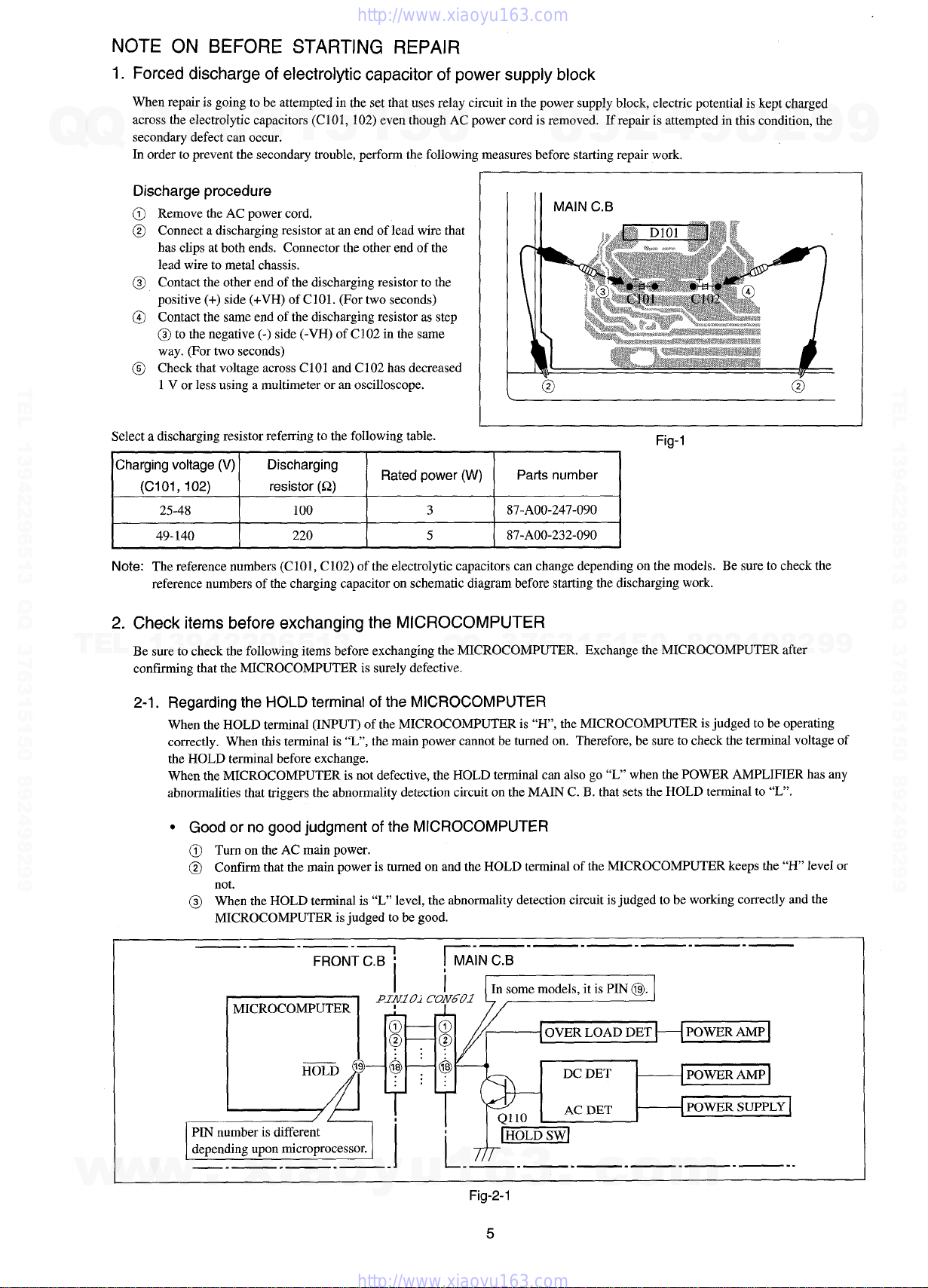
1. Forced discharge of electrolytic capacitor of power supply block
When repair is going to be attempted in the set that uses relay circuit in the power supply block, electric potential is kept charged
across the electrolytic capacitors (C 101, 102) even though AC power cord is removed. If repair is attempted in this condition, the
Q
7
3
secondary defect can occur.
In order to prevent the secondary trouble, perform the following measures before starting repair work.
6
3
1
5
1
5
0
8
9
2
4
9
8
2
9
9
Discharcte txocedure
TEL 13942296513 QQ 376315150 892498299
Select a discharging resistor referring to the following table.
Charging voltage (V)
Note:
2. Check items before exchanging the MICROCOMPUTER
TEL
Be sure to check the following items before exchanging the MICROCOMPUTER. Exchange the MICROCOMPUTER after
confirming that the MICROCOMPUTER is surely defective.
“!
Remove the AC power cord,
Connect a discharging resistor at an end of lead wire that
hasclips at bothends. Connector theotherend of the
lead wire to metal chassis.
Contact the other end of the discharging resistor to the
positive (+) side (+VH) of CIO1. (For two seconds)
Contact the same end of the discharging resistor as step
@to the negative (-) side (-VH) of C102 in the same
way. (For two seconds)
Check that voltage across C 101 and C 102 has decreased
1 V or less using a multimeter or an oscilloscope.
Discharging
(Clol, 102)
25-48
49-140
The reference numbers (C101, C102) of the electrolytic capacitors can change depending on the models. Be sure to check the
reference numbers of the charging capacitor on schematic diagram before starting the discharging work.
resistor (Q)
100 3
220 5
Rated power (W)
13942296513
Q
[, !1
Q
L
Parts number
87-AOO-247-090
87-AOO-232-090
3
7
@
6
3
1
5
1
5
0
Fig-1
8
9
2
4
9
8
@
9
9
2
TEL 13942296513 QQ 376315150 892498299
2-1. Regarding the HOLD terminal of the MICROCOMPUTER
When the HOLD terminal (INPUT) of the MICROCOMPUTER is “H’, the MICROCOMPUTER is judged to be operating
correctly. When this terminal is “L”, the main power cannot be turned on. Therefore, be sure to check the terminal voltage of
the HOLD terminal before exchange.
When the MICROCOMPUTER is not defective, the HOLD terminal can also go “L” when the POWER AMPLIFIER has any
abnormalities that triggers the abnormality detection circuit on the MAIN C. B. that sets the HOLD terminal to “L”.
● Good or no good judgment of the MICROCOMPUTER
Turn on the AC main power.
Confirm that the main power is turned on and the HOLD terminal of the MICROCOMPUTER keeps the “H’ level or
not.
When the HOLD terminal is “L” level, the abnormality detection circuit is judged to be working correctly and the
MICROCOMPUTER is judged to be good.
—.— .— —
FRONT C.B ;
HOLD ‘
h
I k
—i
[
1:
II
5 —
~ — @
@ — $3
: . .
T
.—. — .—-— .—-—
MAIN C.B
r
In some models, it is PIN @.
OVER LOAD DET
DC DET
AC DET
I V1l V
I
I
t
POWER AMP
POWER AMP
POWER SUPPL>
II
w
w
w
dependmg upon uncroprocessor.
~] [7L-
—.— .—. — —
.
xia
o
y
u
.—. —.— .—. —-
1
6
Fig-2-l
5
3
.
c
o
—..
m
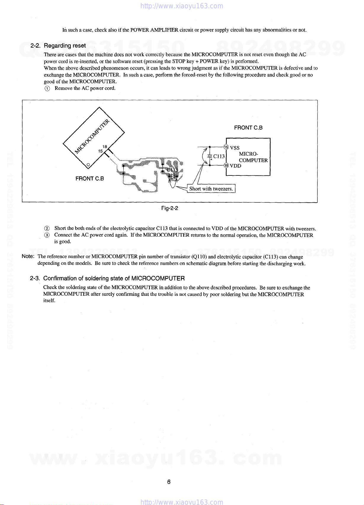
2-2. Regarding reset
Q
There are cases that the machine does not work correctly because the MICROCOMPUTER is not reset even though the AC
Q
power cord is re-inserted, or the software reset (pressing the STOP key + POWER key) is performed.
When the above described phenomenon occurs, it can leads to wrong judgment as if the MICROCOMPUTER is defective and to
exchange the MICROCOMPUTER. In such a case, perform the forced-reset by the following procedure and check good or no
good of the MICROCOMPUTER.
@ Remove the AC power cord.
In such a case, check also if the POWER AMPLIFIER circuit or power supply circuit has any abnormalities or not.
3
7
6
3
1
5
1
5
0
8
9
2
4
9
8
2
9
9
TEL 13942296513 QQ 376315150 892498299
Fig-2-2
@ Short the both ends of the electrolytic capacitor C 113 that is connected to VDD of the MICROCOMPUTER with tweezers.
@ Connect the AC power cord again. If the MICROCOMPUTER returns to the normal operation, the MICROCOMPUTER
is good.
TEL
Note: The reference number or MICROCOMPUTER pin number of transistor (QI 10) and electrolytic capacitor (Cl 13) can change
depending on the models. Be sure to check the reference numbers on schematic diagram before starting the discharging work.
2-3.
13942296513
Confirmation of soldering state of MICROCOMPUTER
Check the soldering state of the MICROCOMPUTER in addition to the above described procedures, Be sure to exchange the
MICROCOMPUTER after surely confirming that the trouble is not caused by poor soldering but the MICROCOMPUTER
itself.
Q
Q
3
7
6
3
1
5
1
5
0
8
9
2
4
9
8
2
9
TEL 13942296513 QQ 376315150 892498299
9
w
w
w
.
xia
o
y
u
1
6
6
3
.
c
o
m
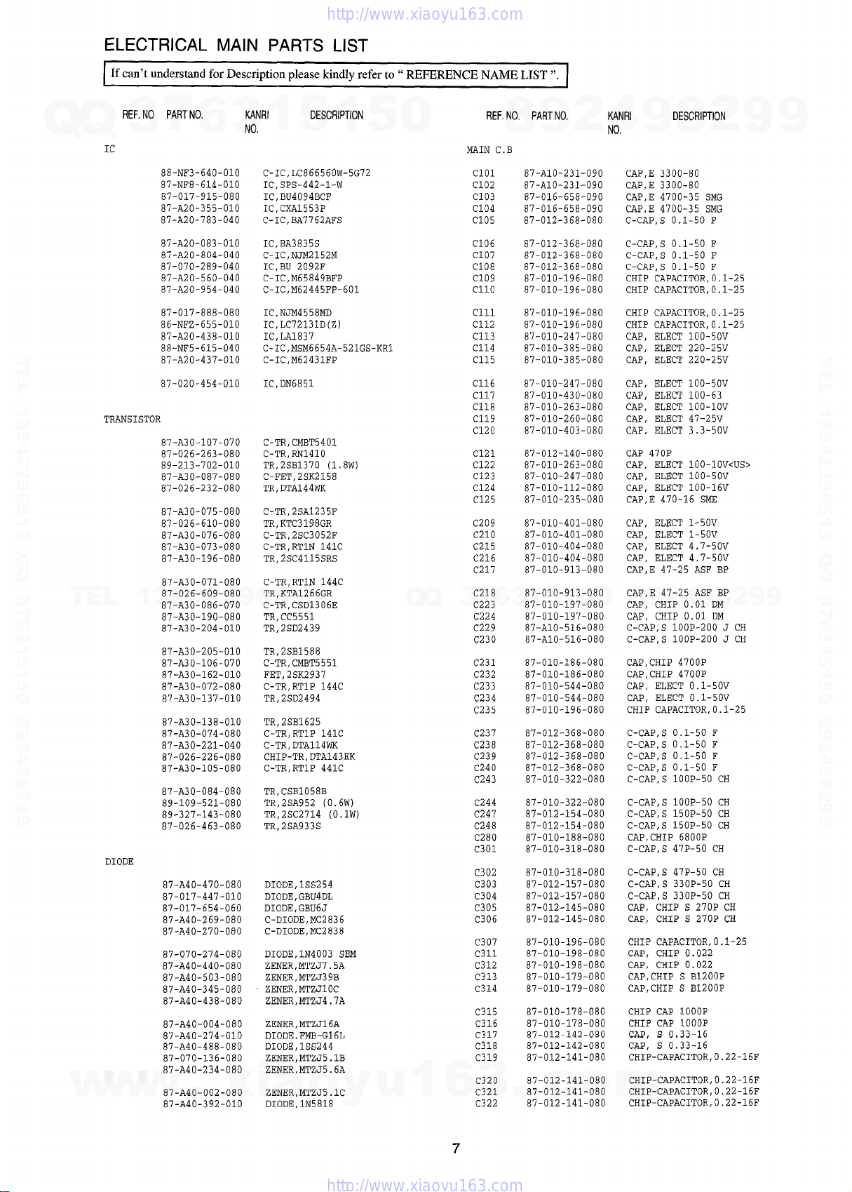
ELECTRICAL MAIN PARTS LIST
If can’t understand for Description please kindly refer to” REFERENCE NAME LIST”.
REF. NO PART NO.
7
Q
Q
3
IC
TEL 13942296513 QQ 376315150 892498299
TRANSISTOR
TEL
w
13942296513
DIODE
w
w
6
88-NF3-64O-O1O
87-NF8-614-O1O
87-017-915-080
87-A2O-355-O1O
87-A20-783-040
87-A2O-O83-O1O
87-A20-804-040
87-070-289-040
87-A20-560-040
87-A20-954-040
87-017-888-080
86-NFZ-655-O1O
87-A2O-438-O1O
88-NF5-615-040
87-A2O-437-O1O
87-020-454-010
87-A3O-1O7-O7O
87-026-263-080
89-213-702-010
87-A30-087-080
87-026-232-080
87-A30-075-080
87-026-610-080
87-A30-076-080
87-A30-073-080
87-A30-196-080
87-A30-071-080
87-026-609-080
87-A30-086-070
87-A30-190-080
87-A3O-2O4-O1O
87-A3O-2O5-O1O
87-A3O-1O6-O7O
87-A3O-162-O1O
87-A30-072-080
87-A3O-137-O1O
87-A3O-138-O1O
87-A30-074-080
87-A30-221-040
87-026-226-080
87-A3O-1O5-O8O
87-A30-084-080
89-109-521-080
89-327-143-080
87-026-463-080
87-A40-470-080
87-017-447-010
87-017-654-060
87-A40-269-080
87-A40-270-080
87-070-274-080
87-A40-440-080
87-A40-503-080
87-A40-345-080
87-A40-438-080
87-A40-004-080
87-A4O-274-O1O
87-A40-488-080
87-070-136-080
87-A40-234-080
87-A40-002-080
.
87-A4O-392-O1O
KANRI DESCRIPTION
1
3
NO.
xia
5
C- IC, LC866560W-5G72
IC, SPS-442-1-W
IC, BU4094BCF
IC, CXA1553P
C-IC, BA7762AFS
IC, BA3835S
C- IC, NJM2152M
IC, BU 2092F
C-IC, M65849BFP
C-IC, M62445FP-601
IC, NJM4558ME
IC, LC72131D(Z)
IC, LA1837
C-IC , MsM6654A-521GS-KR1
C-IC, M62431FP
IC, DN6851
C-TR, CMBT5401
C-TR, RN141O
TR,2SB1370 (1.8w)
C-FET, 2sK2158
TR, DTA144WK
c-TR, 2sA1235F
TR, KTC3198GR
C-TR, 2sc3052F
C-TR, RTIN 141C
TR,2SC4115SRS
C-TR, RTIN 144C
TR,KTA1266GR
C-TR, CSD1306E
TR, CC5551
TR,2SD2439
TR,2SB1588
C-TR, CMBT5551
FET,2SK2937
C-TR, RTIP 144C
TR,2SD2494
TR,2SB1625
C-TR, RTIP 141C
C-TR, DTA114WK
CHIP-TR, DTA143EK
C-TR, RTIP 441C
TR, cSB1058B
TR,2SA952 (0.6w)
TR,2SC2714 (0.lW)
TR,2SA933S
DIODE, 1sS254
DIODE , GBU4DL
DIODE , GBU6J
C-DIODE, MC2836
C-DIODE, MC2838
DIODE, 1N4003 SEM
Z13NER, MTzJ7 5A
ZENER, MTZJ39B
ZENER, MTZJ1OC
ZENER , MTZJ4 . 7A
ZENER,MTZJ16A
DIODE, FMB-G16L
DIODE, 1SS244
ZENER, MTZJ5 , lB
ZENER, MTZJ5 . 6A
ZENER, MTZJ5 . lC
DIODE, 1N5818
o
1
y
5
u
0
Q
1
Q
3
6
MAIN C.B
Clol
C102
C103
C104
C105
C106
C107
C108
C109
Cllo
Clll
C112
C113
C114
C115
C116
C117
C118
C119
C120
C121
C122
C123
C124
C125
C209
C21O
C215
C216
C217
C218
7
C223
C224
c229
C230
c231
c232
c233
c234
c235
c237
c238
C239
c240
C243
c244
C247
c248
c280
C301
c302
C303
C304
C305
c306
C307
C311
C312
C313
C314
C315
c316
C317
c318
C319
c320
c321
3
c322
REF. NO, PART NO.
6
8
87-A1O-231-O9O
87-A1O-231-O9O
87-016-658-090
87-016-658-090
87-012-368-080
87-012-368-080
87-012-368-080
87-012-368-080
87-010-196-080
87-010-196-080
87-010-196-080
87-010-196-080
87-010-247-080
87-010-385-080
87-010-385-080
87-010-247-080
87-010-430-080
87-010-263-080
87-010-260-080
87-010-403-080
87-012-140-080
87-010-263-080
87-010-247-080
87-010-112-080
87-010-235-080
87-010-401-080
87-010-401-080
87-010-404-080
87-010-404-080
87-010-913-080
87-010-913-080
1
3
87-010-197-080
87-010-197-080
87-A1O-516-O8O
87-A1O-516-O8O
87-010-186-080
87-010-186-080
87-010-544-080
87-010-544-080
87-010-196-080
87-012-368-080
87-012-368-080
87-012-368-080
87-012-368-080
87-010-322-080
87-010-322-080
87-012-154-080
87-012-154-080
87-010-188-080
87-010-318-080
87-010-318-080
87-012-157-080
87-012-157-080
87-012-145-080
87-012-145-080
87-010-196-080
87-010-198-080
87-010-198-080
87-010-179-080
87-010-179-080
87-010-178-080
87-010-178-080
97-012-142-080
87-012-142-080
87-012-141-080
87-012-141-080
87-012-141-080
.
87-012-141-080
9
5
c
2
1
U4NRI DESCRIPTION
4
9
NO.
CAP, E 3300-80
CAP, E 3300-80
CAP, E 4700-35 SMG
CAP, E 4700-35 SMG
C-CAP, S 0.1-50 F
C-CAP, S 0.1-50 F
C-CAP, S 0.1-50 F
C-CAP, S 0.1-50 F
CHIP CAPACITOR, 0.1-25
CHIP CAPACITOR, 0.1-25
CHIP CAPACITOR, 0.1-25
CHIP CAPACITOR, 0.1-25
CAP, ELECT 1OO-5OV
CAP, ELECT 220-25V
CAP, ELECT 220-25V
CAP, ELECT 1OO-5OV
CAP, ELECT 100-63
CAP, ELECT 100-1OV
CAP , ELECT 47-25V
CAP, ELECT 3.3-50V
CAP 470P
CAP, ELECT 100-1 OV<US>
CAP, ELECT 1OO-5OV
CAP, ELECT 100-16V
CAP, E 470-16 SME
CAP , ELECT 1-50V
CAP, ELECT 1-50V
CAP, ELECT 4.7-50V
CAP, ELECT 4.7-50V
CAP, E 47-25 ASF BP
CAP, E 47-25 ASF BP
9
8
0
5
o
CAP, CHIP 0.01 DM
CAP, CHIP 0.01 DM
C-CAP, S 1OOP-2OO J CH
C-CAP, S 1OOP-2OO J CH
CAP, CHIP 4700P
CAP, CHIP 4700P
CAP, ELECT 0.1-50V
CAP, ELECT 0.1-50V
CHIP CAPACITOR, 0.1-25
C-CAP, S 0.1-50 F
C-CAP, S 0.1-50 F
C-CAP, S 0.1-50 F
C-CAP, S 0.1-50 F
C-CAP, S 1OOP-5O CH
C-CAP, S 1OOP-5O CH
C-CAP, S 150P-50 CH
C-CAP, S 150P-50 CH
CAP, CHIP 6800P
C-CAP, S 47P-50 CH
C-CAP, S 47P-50 CH
C-CAP, S 330P-50 CH
C-CP.P, S 330P-50 CH
CAP, CHIP S 270P CH
CAP, CHIP S 270P CH
CHIP CAPACITOR, 0.1-25
CAP, CHIP 0.022
CAP, CHIP 0.022
CAP, CHIP S B1200P
CAP, CHIP S B1200P
CHIP CAP 1000P
CHIP CAP 1000P
CAP, S 0033-16
CAP, S 0.33-16
CHIP-CAPACITOR, O.22-16F
CHIP-CAPACITOR, 0. 22-16F
CHIP-CAPACITOR, 0. 22-16F
m
CHIP-CAPACITOR, 0. 22-16F
8
2
4
2
9
8
9
2
9
9
TEL 13942296513 QQ 376315150 892498299
9
REF. NO. PART NO.
Q
Q
C324
C325
C327
C328
C332
C335
C336
C337
C339
C340
C351
C352
C354
C355
c356
TEL 13942296513 QQ 376315150 892498299
C357
C358
C359
C360
C363
C370
C371
C372
C373
C374
C375
C376
C378
C381
C382
C383
C384
C385
TEL
C386
C401
C402
C403
C404
C405
C406
C407
C408
C409
C41O
C411
C412
C415
C416
C453
C454
C457
C458
C459
C460
C461
C463
c464
C516
C551
C552
C553
C601
C602
C613
C614
C619
C620
C621
C622
w
C625
3
87-010-260-080
87-010-370-080
87-010-404-080
87-010-404-080
87-010-196-080
87-010-401-080
87-010-401-080
87-010-196-080
87-010-196-080
87-010-196-080
87-012-140-080
87-012-140-080
87-010-175-080
87-010-178-080
87-010-260-080
87-010-197-080
87-010-183-080
87-010-183-080
87-010-183-080
87-A1O-772-O8O
87-010-196-080
87-010-177-080
87-010-177-080
87-010-179-080
87-010-179-080
87-010-545-080
87-010-545-080
87-010-196-080
87-010-197-080
87-010-318-080
87-010-197-080
87-010-402-080
87-010-184-080
13942296513
87-010-196-080
87-010-405-080
87-010-405-080
87-010-184-080
87-010-184-080
87-010-193-080
87-010-193-080
87-010-405-080
87-010-405-080
87-010-380-080
87-010-380-080
87-010-405-080
87-010-112-080
87-010-184-080
87-010-184-080
87-010-544-080
87-010-544-080
87-010-402-080
87-010-402-080
87-010-402-080
87-010-402-080
87-010-545-080
87-010-402-080
87-010-402-080
87-010-196-080
87-010-401-080
87-010-263-080
87-010-380-080
87-010-180-080
87-010-180-080
87-016-081-080
87-016-081-080
87-010-185-080
87-010-185-080
87-010-401-080
87-010-401-080
w
w
87-010-405-080
KANRI
7
NO,
6
CAP , ELECT 47 -25V
CAP, E 330-6.3 SME
CAP, ELECT 4.7-50V
CAP, ELECT 4.7-50V
CHIP CAPACITOR, 0.1-25
CAP , ELECT 1-50V
CAP , ELECT 1-50V
CHIP CAPACITOR, 0.1-25
CHIP CAPACITOR, 0.1-25
CHIP CAPACITOR, 0.1-25
CAP 470P
CAP 470P
CAP 560P
CHIP CAP 1000P
CAP , ELECT 47-25V
CAP, CHIP 0.01 DM
C-CAP, S 2700P-50 B
C-CAP, S 2700P-50 B
C-CAP, S 2700P-50 B
CAP, M 5600P-50 J
CHIP CAPACITOR, 0.1-25
C-CAP, S 820P-50 SL
C-CAP, S 820P-50 SL
CAP, CHIP S B1200P
CAP, CHIP S B1200P
CAP, ELECT 0.22-50V
CAP, ELECT O .22-50V
CHIP CAPACITOR, 0.1-25
CAP, CHIP 0.01 DM
C-CAP, S 47P-50 CH
CAP, CHIP 0.01 DM
CAP, ELECT 2.2-50V
CHIP CAPACITOR 3300P(K)
CHIP CAPACITOR, 0.1-25
CAP, ELECT 1O-5OV
CAP , ELECT 10-5 OV
CHIP CAPACITOR 3300P(K)
CHIP CAPACITOR 3300P(K)
CHIP CAPACITOR, 0.033
CHIP CAPACITOR, 0.033
CAP , ELECT 10-5 OV
CAP , ELECT 10-5 OV
CAP , ELECT 47-16V
CAP , ELECT 47-16V
CAP , ELECT 10-5 OV
CAP, ELECT 100-16v
CHIP CAPACITOR 3300P (K)
CHIP CAPACITOR 3300P(K)
CAP, ELECT 0.1-50V
CAP, ELECT 0.1-50V
CAP, ELECT 2.2-50V
CAP, ELECT 2.2-50V
CAP, ELECT 2.2-50V
CAP, ELECT 2.2-50V
CAP, ELECT 0.22-50V
CAP, ELECT 2.2-50V
CAP, ELECT 2.2-50V
CHIP CAPACITOR, 0.1-25
CAP , ELECT 1-50V
CAP, ELECT 100-1OV
CAP , ELECT 47 -16V
C-CER 1500P
C-CER 1500P
C-CAP, S 0.1-16 RK
C-CAP, S 0.1-16 RK
C-CAP, S 3900P-50 B
C-CAP, S 3900P-50 B
CAP, ELECT 1-50V
CAP, ELECT 1-50V
.
CAP , ELECT 1O-5OV
DESCRIPTION
1
3
xia
5
o
1
y
5
u
REF. NO. PART NO.
0
C626
C629
c630
C631
C632
C633
C634
C635
C636
C637
C641
C667
C701
C702
C703
C704
C709
C711
C712
C713
C714
C721
C722
C723
C725
C727
C728
C755
C756
C757
C758
C761
C762
Q
Q
C763
C764
C765
C766
C767
C768
C769
C770
C771
C772
C773
C774
C775
C776
C777
C778
C779
c780
C781
C782
C783
c784
C785
c786
c787
C788
C789
C790
C791
C793
C794
C795
C796
C797
C798
C799
1
6
C812
87-010-405-080
87-010-405-080
87-010-213-080
87-010-194-080
87-010-263-080
87-010-263-080
87-010-196-080
87-010-196-080
87-010-194-080
87-010-183-080
87-012-368-080
87-012-368-080
87-010-381-080
87-010-404-080
87-010-197-080
87-010-197-080
87-010-322-080
87-010-263-080
87-010-196-080
87-010-197-080
87-010-197-080
87-010-312-080
87-010-312-080
87-010-178-080
87-010-178-080
87-010-196-080
87-010-248-080
87-010-197-080
87-010-197-080
87-010-318-080
87-010-149-080
87-010-196-080
87-010-197-080
7
3
87-010-194-080
87-010-319-080
87-010-197-080
87-010-197-080
87-010-405-080
87-010-197-080
87-010-408-080
87-015-821-080
87-010-407-080
87-010-194-080
87-010-196-080
87-010-263-080
87-010-404-080
87-010-197-080
87-010-400-080
87-010-401-080
87-010-401-080
87-010-196-080
87-010-405-080
87-010-405-080
87-015-819-080
87-010-197-080
87-010-403-080
87-010-403-080
87-010-184-080
87-010-184-080
87-010-179-080
87-010-179-080
87-010-405-080
87-010-177-080
87-010-406-080
87-010-596-080
87-010-403-080
87-010-182-080
87-010-182-080
87-010-194-080
3
87-010-197-080
8
6
3
.
2
5
o
DESCRIPTION
4
0
KANRI
NO,
9
CAP, ELECT 1O-5OV
CAP , ELECT 1O-5OV
C-CAP, S 0.015-50 B
CAP, CHIP 0.047
CAP, ELECT 100-1OV
CAP, ELECT 100-1OV
CHIP CAPACITOR, 0.1-25
CHIP CAPACITOR, 0.1-25
CAP, CHIP 0.047
C-CAP, S 2700P-50 B
C-CAP, S 0.1-50 F
C-CAP, S 0.1-50 F
CAP, ELECT 330-16v
CAP, ELECT 4.7-50V
CAP, CHIP 0.01 DM
CAP, CHIP 0.01 DM
C-CAP, S 1OOP-5O CH
CAP, ELECT 100-1OV
CHIP CAPACITOR, 0.1-25
CAP, CHIP 0.01 DM
CAP, CHIP 0.01 DM
C-CAP, S 15P-50 CH
C-CAP, S 15P-50 CH
CHIP CAP 1000P
CHIP CAP 1000P
CHIP CAPACITOR, 0.1-25
CAP, ELECT 22 O-1OV
CAP, CHIP 0.01 DM
CAP, CHIP 0.01 DM
C-CAP, S 47P-50 CH
C-CAP, S 5P-50 CH
CHIP CAPACITOR, 0.1-25
CAP, CHIP 0.01 DM
1
5
1
CAP, CHIP 0.047
C-CAP, S 56P-50 CH
CAP, CHIP 0.01 DM
CAP, CHIP 0.01 DM
CAP , ELECT 10-5 OV
CAP, CHIP 0.01 DM
CAP , ELECT 47-50V
C-CAP 0.047
CAP , ELECT 33 -50V
CAP, CHIP 0.047
CHIP CAPACITOR, 0.1-25
CAP, ELECT 100-1OV
CAP, ELECT 4.7-50V
CAP, CHIP 0.01 DM
CAP, ELECT O .47-50V
CAP , ELECT 1-50V
CAP , ELECT 1-5 OV
CHIP CAPACITOR, 0.1-25
CAP , ELECT 10-50V
CAP , ELECT 10-5 OV
CAPACITOR, 0.01
CAP, CHIP 0.01 DM
CAP, ELECT 3.3-50V
CAP, ELECT 3.3-50V
CHIP CAPACITOR 3300P(K)
CHIP CAPACITOR 3300P (K)
CAP, CHIP S B1200P
CAP, CHIP S B1200P
CAP , ELECT 1O-5OV
C-CAP, S 820P-50 SL
CAP, ELECT 22-50
CAP, S 0.047-16
CAP, ELECT 3.3-50V
C-CAP, S 2200P-50 B
C-CAP, S 2200P-50 B
CAP, CHIP 0.047
c
CAP, CHIP 0.01 DM
9
9
8
m
2
8
4
2
9
8
9
2
9
9
TEL 13942296513 QQ 376315150 892498299
9
8
REF. NO. PART NO.
Q
Q
c814
c820
c821
C822
c823
C828
c829
C959
C960
c961
CF801
CF802
CN35 1
FB601
FC451
TEL 13942296513 QQ 376315150 892498299
FC602
FFE801
J203
J211
J601
J801
L201
L202
L301
L302
L351
L771
L772
L781
L791
L792
L832
L981
TEL
R123
R237
R238
R239
R240
RY101
SFR301
SFR302
SFR303
SFR304
SFR305
SFR306
SFR351
SFR352
TH2 01
TH202
W104
W104
WH102
WH102
X721
FRONT C . B
Clol 87-010-182-080
C102
C104
C105
C106 87-010-320-080
C107 87-012-157-080
C108 87-010-498-040
C109
Cllo 87-A1O-369-O8O
Clll
C112 87-010-196-080
C113 87-A1O-189-O4O
w
w
C114
7
3
13942296513
w
87-010-197-080
87-010-408-080
87-010-197-080
87-010-197-080
87-010-197-080
87-010-196-080
87-010-196-080
87-010-196-080
87-010-196-080
87-010-152-080
87-008-261-010
87-008-261-010
88-NF3-666-O1O
87-A50-190-080
88-905-451-110
88-906-261-110
A8-8zA-190-030
87-033-240-010
87-A6O-483-O1O
87-A6O-4O2-O1O
87-A6O-2O2-O1O
87-003-383-010
87-003-383-010
87-A5O-O49-O1O
87-A5O-O49-O1O
87-007-342-010
87-A5O-266-O1O
87-A9O-733-O1O
87-005-847-080
87-A5O-2O9-O1O
87-A5O-2O9-O1O
86-NFz-694-080
87-NF4-65O-O1O
87-022-200-080
87-AOO-262-080
87-AOO-262-080
87-AOO-262-080
87-AOO-262-080
87-A9O-464-O1O
87-A90-636-080
87-A90-636-080
87-A90-636-080
87-A90-636-080
87-A90-637-080
87-A90-637-080
87-A90-637-080
87-A90-637-080
87-A90-221-080
87-A90-221-080
88-NF3-665-O1O
88-NF3-665-O1O
87-A9O-142-O1O
87-A9O-142-O1O
87-A7O-O61-O1O
87-010-182-080
87-010-312-080
87-010-316-080
87-010-401-040
87-010-196-080
.
87-010-196-080
6
KANRI
3
NO.
CAP, CHIP 0.01 DM
CAP, ELECT 47 -50V
CAP, CHIP 0.01 DM
CAP, CHIP 0.01 DM
CAP, CHIP 0.01 DM
CHIP CAPACITOR, 0.1-25
CHIP CAPACITOR, 0.1-25
CHIP CAPACITOR, 0.1-25
CHIP CAPACITOR, 0.1-25
C-CAP, S 8P-50 CH
FILTER, SFE1O , 7MA5-A
FILTER, SFE1O . 7MA5-A
CONN ASSY, 8P RPB
C-COIL, S BLM21A102S
FF-CABLE, 5P 1.25
FF-CABLE,6P 1.25 2601fw
8zA-1 FEUNM
TERMINAL, SP 4P32SV1-05
JACK, DIA6 .3 BLK ST W/S KM
JACK, PIN 6P R/W HSF-246V30
TERMINAL, ANT 4P MSP-154V-02
COIL, lUH-S
COIL, lUH-S
coIL, TRiAP 85 K(coI)
COIL, TRAP 85 K(COI)
coIL, osc 85K BIAS
coIL, FM DET-2N (TOK)
FLTR, PCFAZH-450 (TOK)
COIL, 2 .2 UH(CECS)
COIL, lPOLE MPX (MIT)
coIL, lPOLE MPX (MIT)
COIL, 2. 2UH K CECS
COIL, AM PACK 4N (TOK)
RESISTOR, METAL 0.56 lW<US>
RES, M/F 0.15-2W J
RES, M/F 0.15-2w J
RES, M/F 0.15-2w J
RES, M/F 0.15-2w J
RELAY, DG12D2-O(M)
SFR,33K H RH0638C LG
SFR,33K H RH0638C LG
SFR, 33K H RH0638C LG
SFR,33K H RH0638C LG
SFR, 47K H RH0638c LG
SFR,47K H RH0638C LG
SFR, 47K H RH0638C LG
SFR,47K H RH0638c LG
c-TRivs, 100 K<LHs>
c-THMs, 100 K<LHs>
F-CABLE, 7P -2.5 (GETA)
F-CABLE, 7P -2.5 (GETA)
HOLDER, 51 O52-O71O VO
HOLDER, 51 O52-O71O VO
VIB, XTAL 4.500MHZ CSA-309
C-CAP, S 2200P-50 B
C-CAP, S 2200P-50 B
C-CAP, S 15P-50 CH
C-CAP, S 33P-50 CH
CHIP CAP 68P
C-CAP, S 330P-50 CH
CAP, E 10-16 GAS
CAP, E 1-50 SME
C-CAP, S 0.47-16 K B
CHIP CAPACITOR, 0.1-25
CHIP CAPACITOR, 0.1-25
CAP, E 220-10
xia
CHIP CAPACITOR, 0.1-25
1
DESCRIPTION
5
o
1
y
5
u
0
Q
Q
1
C115
C116
C117
C118
C119
C120
C121
C122
C123
C124
C125
C126
C127
C128
C129
C130
C150
C151
C240
C249
c250
c251
c252
c281
C282
C301
c302
C303
C351
C352
C353
C354
C355
3
C356
C357
C501
C502
C503
C504
C505
c506
C507
c508
C509
C51O
C511
C512
C513
C514
C515
C516
C518
C519
C601
C602
c603
C604
C605
C607
C608
C609
C611
C613
C614
c621
C634
C802
6
C801
C803
C901
REF. NO, PART NO,
6
7
3
8
87-010-178-080
87-010-494-040
87-010-263-040
87-010-194-080
87-010-408-040
87-010-404-040
87-010-404-040
87-010-194-080
87-010-196-080
87-010-196-080
87-010-196-080
87-010-263-040
87-010-196-080
87-010-309-080
87-012-157-080
87-A1O-189-O4O
87-010-194-080
87-010-194-080
87-010-176-080
87-010-176-080
87-010-176-080
87-010-176-080
87-010-178-080
87-010-182-080
87-010-182-080
87-010-196-080
87-010-196-080
87-010-196-080
87-012-158-080
87-010-196-080
87-010-196-080
87-010-196-080
87-010-196-080
1
3
87-010-196-080
87-010-196-080
87-A1O-8O4-O8O
87-A1O-8O4-O8O
87-012-141-080
87-010-186-080
87-010-178-080
87-A1O-8O3-O8O
87-A1O-8O3-O8O
87-010-186-080
87-010-178-080
87-012-141-080
87-010-196-080
87-010-263-040
87-A1O-723-O4O
87-A1O-723-O4O
87-010-183-080
87-010-183-080
87-010-196-080
87-010-263-040
87-010-405-040
87-010-186-080
87-010-498-040
87-010-499-040
87-010-196-080
87-010-321-080
87-010-196-080
87-010-545-040
87-010-177-080
87-010-322-080
87-010-248-040
87-010-405-040
87-015-678-040
87-010-263-040
87-010-196-080
87-010-400-040
.
87-010-421-040
9
1
5
c
KANRI DESCRIPTION
4
2
5
o
0
9
NO,
CHIP CAP 1000P
CAP, E 1-50 GAS
CAP, E 100-10
CAP, CHIP 0.047
CAP, E 47-50 SME
CAP, E 4,7-50 SME
CAP, E 4<7-50 SME
CAP, CHIP 0.047
CHIP CAPACITOR, 0.
CHIP CAPACITOR, 0.
CHIP CAPACITOR, 0.
CAP, E 100-10
CHIP CAPACITOR, 0.1-25
C-CAP,1OOOP-5O CH
C-CAP, S 330P-50 CH
CAP, E 220-10
CAP, CHIP 0.047
CAP, CHIP 0.047
C-CAP, S 680P-50 SL
C-CAP, S 680P-50 SL
C-CAP, S 680P-50 SL
C-CAP, S 680P-50 SL
CHIP CAP 1000P
C-CAP, S 2200P-50 B
C-CAP, S 2200P-50 B
CHIP CAPACITOR, 0.1-25
CHIP CAPACITOR, 0.1-25
CHIP CAPACITOR, 0.1-25
C-CAP, S 390P-50 CH
CHIP CAPACITOR, 0.1-25
CHIP CAPACITOR, 0.1-25
CHIP CAPACITOR, 0.1-25
CHIP CAPACITOR, 0.1-25
9
8
CHIP CAPACITOR, 0.1-25
CHIP CAPACITOR, 0.1-25
C-CAP, S 0.1-25 J B
C-CAP, S 0.1-25 J B
CHIP-CAPACITOR, 0. 22-16F
CAP, CHIP 4700P
CHIP CAP 1000P
C-CAP, S 0.068-16 J B CM
C-CAP, S 0.068-16 J B CM
CAP, CHIP 4700P
CHIP CAP 1000P
CHIP-CAPACITOR, O .22-16F
CHIP CAPACITOR, 0.1-25
CAP, E 100-10
CAP, E 2.2-35 5L SSE
CAP, E 2.2-35 5L SSE
C-CAP, S 2700P-50 B
C-CAP, S 2700P-50 B
CHIP CAPACITOR, 0.1-25
CAP, E 100-10
CAP, E 10-50
CAP, CHIP 4700P
CAP, E 10-16 GAS
CAP, E 22-6.3 GAS
CHIP CAPACITOR, 0.1-25
CHIP CAPACITOR, 82P (J)
CHIP CAPACITOR, 0.1-25
CAP, E 0.22-50 SME
C-CAP, S 820P-50 SL
C-CAP, S 1OOP-5O CH
CAP, E 220-10 SME
CAP, E 10-50
CAP, E 22-10 M 7L SRA
CAP, E 100-10
CHIP CAPACITOR, 0.1-25
CAP, E 0.47-50
m
CAPE 4.7-50 5L
2
8
4
2
9
-25
-25
-25
8
2
9
9
9
TEL 13942296513 QQ 376315150 892498299
9
9

REF. NO. PART NO.
Q
Q
C902
C905
c906
C907
C908
C91O
C911
C912
C913
C914
C915
C916
C917
C918
C919
TEL 13942296513 QQ 376315150 892498299
C920
C921
C922
C924
C925
C926
C927
C928
C929
C930
C931
C932
C933
C934
C935
C965
C966
CN302
CN502
FC102
FC502
FC701
FL101
J601
J602
L901
LED4 01
LED402
LED403
LED404
LED4 05
LED406
LED407
LED4 08
LED409
LED41 o
LED411
LED412
LED41 3
LED414
LED41 5
LED416
LED417
LED418
LED419
LED42 o
LED421
LED431
LED43 2
LED433
LED434
LED435
A %&
~ PR107
TEL
w
3
87-A1O-818-O4O
87-010-493-040
87-010-196-080
87-010-196-080
87-010-400-040
87-A1O-369-O8O
87-010-197-080
87-010-196-080
87-010-185-080
87-010-596-080
87-010-181-080
87-010-198-080
87-010-176-080
87-010-188-080
87-012-145-080
87-010-183-080
87-015-696-040
87-015-696-040
87-010-198-080
87-A1O-369-O8O
87-010-197-080
87-010-196-080
87-010-185-080
87-010-596-080
87-010-181-080,
87-010-198-080
87-010-176-080
87-010-188-080
87-012-145-080
87-010-183-080
87-010-313-080
87-010-313-080
87-099-201-010
13942296513
87-099-209-010
88-912-201-110
88-904-261-110
88-915-181-110
88-NF3-611-O1O
87-A6O-284-O1O
87-A6O-284-O1O
87-007-340-010
87-A40-259-080
87-A40-259-080
87-A40-259-080
87-A40-259-080
87-A40-259-080
87-070-197-080
87-070-197-080
87-070-197-080
87-070-197-080
87-070-197-080
87-070-197-080
87-070-197-080
87-070-197-080
87-070-197-080
87-070-197-080
87-070-281-080
87-070-281-080
87-070-281-080
87-070-281-080
87-070-281-080
87-070-281-080
87-070-278-010
87-070-278-010
87-070-290-010
87-070-290-010
87-070-278-010
87-070-278-010
87-A9O-41O-O8O
w
w
87-A90-560-080
KANRI DESCRIPTION
7
6
NO,
CAP, E 100-16 7LSF.A SERIES
CAP, E 0.47-50 GAS
CHIP CAPACITOR, 0.1-25
CHIP CAPACITOR, 0.1-25
CAP, E 0.47-50
C-CAP, S 0.47-16 K B
CAP, CHIP 0.01 DM
CHIP CAPACITOR, 0.1-25
C-CAP, S 3900P-50 B
CAP, S 0.047-16
CAP, CHIP S 1800P
CAP, CHIP 0.022
C-CAP, S 680P-50 SL
CAP, CHIP 6800P
CAP, CHIP S 270P CH
C-CAP, S 2700P-50 B
CAP, E 2.2-50 SRA
CAP, E 2.2-50 SRA
CAP, CHIP 0.022
C-CAP, S 0,47-16 K B
CAP, CHIP 0.01 DM
CHIP CAPACITOR, 0.1-25
C-CAP, S 3900P-50 B
CAP, S 0.047-16
CAP, CHIP S 1800P
CAP, CHIP 0.022
C-CAP, S 680P-50 SL
CAP, CHIP 6800P
CAP, CHIP S 270P CH
C-CAP, S 2700P-50 B
CAP, CHIP 18P
CAP, CHIP 18P
CONN,8P 6216 H
coim,4p 6216H
FF-CABLE,12P-1.25
FF-CABLE, 4P 1.25 260MM
FF-CABLE,15P 1.25
FL, BJ604GK-8NF3
JACK ,3. 5M0 (MSC )
JACK, 3. 5M0 (MSC)
COIL, CLOCK 4. 19MHZ
LED ,SLR-342VCT31 RED
LED, SLR-342VCT31 RED
LED ,SLR-342vCT3 1 RED
LED, SLR-342VCT31 RED
LED ,SLR-342vCT3 1 RED
LED, SLP7118C-51-S-T1
LED, SLP7118C-51-S-T1
LED, SLP7118C-51-S-T1
LED, SLP7118C-51-S-T1
LED, SLP7118C-51-S-T1
LED, SLP7118C-51-S-T1
LED, SLP7118C-51-S-T1
LED, SLP7118C-51-S-T1
LED, SLP7118C-51-S-T1
LED, SLP7118C-51-S-T1
LED, SLZ736A-25-S-T1
LED, SLZ736A-25-S-T1
LED, SLZ736A-25-S-T1
LED, SLZ736A-25-S-T1
LED, SLZ736A-25-S-T1
LED, SLZ736A-25-S-T1
LED, SLZ-738A-24-S
LED, SLZ-738A-24-S
LED, SLZ 936-30-S
LED, SLZ 936-30-s
LED, SLZ-738A-24-S
LED, SLZ-738A-24-S
FUSE, O .5A 125v 251<US>
.
xia
PROTECTOR ,63 OA 6 OV<LHS>
3
1
5
o
1
y
5
u
REF. NO. PART NO.
0
R243
R244
R245
R246
S302
S306
S307
s308
S316
S317
S318
S319
s320
s321
s322
S323
s324
S325
S326
S327
s328
s329
S330
S331
s332
S333
S334
S335
s336
S337
s338
S339
S340
Q
Q
S341
s342
S343
S344
S345
S370
S371
S372
S373
S374
S375
Swl 01
Xlol
HIFI-AMP (
Clol
C102
C103
C104
C106
C201
C202
c207
c208
C209
C21O
C211
C212
C213
C214
C217
C218
C219
C220
C221
1
3
6
87-AOO-258-080
87-AOO-258-080
87-AOO-258-080
87-AOO-258-080
87-A90-756-080
87-A90-756-080
87-A90-756-080
87-A90-756-080
87-A90-756-080
87-A90-756-080
87-A90-756-080
87-A90-756-080
87-A90-756-080
87-A90-756-080
87-A90-756-080
87-A90-756-080
87-A90-756-080
87-A90-756-080
87-A90-756-080
87-A90-756-080
87-A90-756-080
87-A90-756-080
87-A90-756-080
87-A90-756-080
87-A90-756-080
87-A90-756-080
87-A90-756-080
87-A90-756-080
87-A90-756-080
87-A90-756-080
87-A90-756-080
87-A90-756-080
87-A90-756-080
87-A90-756-080
87-A90-756-080
87-A90-756-080
87-A90-756-080
87-A90-756-080
87-A90-756-080
87-A90-756-080
87-A90-756-080
87-A90-756-080
87-A90-756-080
87-A90-756-080
87-A9O-535-O1O
87-A70-070-080
:.B
87-012-368-080
87-012-368-080
87-010-917-090
87-010-917-090
87-010-182-080
87-010-112-080
87-010-378-080
87-010-401-080
87-010-401-080
87-010-181-080
87-010-181-080
87-010-545-080
87-010-545-080
87-010-184-080
87-010-184-080
87-010-402-080
87-010-402-080
87-A1O-812-O8O
87-A1O-812-O8O
87-010-913-080
6
7
3
8
3
.
KANRI DESCRIPTION
2
9
NO.
RES, M/F 0.22-lW J
RES, M/F 0.22-lW J
RES, M/F 0.22-lW J
RES, M/F 0.22-lW J
SW, TACT SINKO
SW, TACT SINKO
SW, TACT SINKO
SW, TACT SINKO
SW, TACT SINKO
SW, TACT SINKO
SW, TACT SINKO
SW, TACT SINKO
SW, TACT SINKO
SW, TACT SINKO
SW, TACT SINKO
SW, TACT SINKO
SW, TACT SINKO
SW, TACT SINKO
SW, TACT SINKO
SW, TACT SINKO
SW, TACT SI~O
SW, TACT SINKO
SW, TACT SINKO
SW, TACT SINKO
SW, TACT SINKO
SW, TACT SINKO
SW, TACT SINKO
SW, TACT SINKO
SW, TACT SINKO
SW, TACT SINKO
SW, TACT SINKO
SW, TACT SINKO
SW, TACT SINKO
0
5
1
5
1
SW, TACT SINKO
SW, TACT SINKO
SW, TACT SINKO
SW, TACT SINKO
SW, TACT SINKO
SW, TACT SINKO
SW, TACT SINKO
SW, TACT SINKO
SW, TACT SINKO
SW, TACT SINKO
SW, TACT SINKO
SW, RTRY EC16B24304
VIB, CER 5. 76MHz CRHF
C-CAP, S 0.1-50 F
C-CAP, S 0.1-50 F
CAP, E 3300-50 M SMG
CAP, E 3300-50 M SMG
C-CAP, S 2200P-50 B
CAP, ELECT 100-16V
CAP , ELECT 10- 16V
CAP , ELECT 1-5 OV
CAP , ELECT 1-50V
CAP, CHIP S 1800P
CAP, CHIP S 1800P
CAP, ELECT 0.22-50V
CAP, ELECT 0.22-50V
CHIP CAPACITOR 3300P (K)
CHIP CAPACITOR 3300P(K)
CAP, ELECT 2.2-50V
CAP, ELECT 2.2-50V
C-CAP, S 220P-200 J CH
C-CAP, S 220P-200 J CH
CAP, E 47-25 ASF BP
c
o
4
8
m
9
9
8
2
4
9
2
8
9
2
9
9
TEL 13942296513 QQ 376315150 892498299
9
10
Q
Q
C222
C223
c224
C225
c226
C227
c228
c231
C232
C234
c235
c240
J201
L201
L202
REF, NO, PART NO,
3
7
87-010-913-080
87-010-544-080
87-010-544-080
87-010-993-080
87-010-993-080
87-010-196-080
87-010-196-080
87-012-153-080
87-012-153-080
87-016-285-080
87-016-285-080
87-010-322-080
87-A6O-545-O1O
87-003-383-010
87-003-383-010
6
TEL 13942296513 QQ 376315150 892498299
RY101
KEY C.B
FC302
LED447
LED448
LED449
LED45 o
LED451
LED452
LED453
LED454
LED455
LED456
LED472
LED47 3
LED47 4
TEL
LED47 5
LED476
S309
S31O
S311
S312
S313
S314
S315
DIAL C. E
C287
FC802
LED460
LED461
LED46 2
LED463
LED464
LED46 5
LED466
LED467
LED468
LED46 9
LED47 o
LED471
Swl 02
87-045-382-010
88-908-231-110
87-070-197-080
87-070-197-080
87-070-197-080
87-070-197-080
87-070-197-080
87-070-197-080
87-070-197-080
87-070-197-080
87-070-197-080
87-070-197-080
87-070-197-080
87-070-197-080
87-070-197-080
13942296513
87-070-197-080
87-070-197-080
87-A90-756-080
87-A90-756-080
87-A90-756-080
87-A90-756-080
87-A90-756-080
87-A90-756-080
87-A90-756-080
87-010-196-080
88-910-131-110
87-017-368-080
87-017-368-080
87-017-368-080
87-017-368-080
87-017-368-080
87-017-368-080
87-017-368-080
87-017-368-080
87-017-368-080
87-017-368-080
87-017-368-080
87-017-368-080
87-A9O-784-O1O
KANRI DESCRIPTION
1
3
NO.
JACK, PIN 4P W/R
5
CAP, E 47-25 ASF BP
CAP, ELECT 0.1-50V
CAP, ELECT 0.1-50V
C-CAP, S 0.056-25 B
C-CAP, S 0.056-25 B
CHIP CAPACITOR, 0.1-25
CHIP CAPACITOR, 0.1-25
C-CAP, S 120P-50 CH
C-CAP, S 120P-50 CH
CAP, E 47-1 OOSME
CAP, E 47-1 OOSME
C-CAP, S 1OOP-5O CH
COIL, lUI-S
COIL, lUH-S
RELAY, OUAZ-SH-112L
FF-CABLE, 8P 1.25
LED, SLP7118C-51-S-T1
LED, SLP7118C-51-S-T1
LED, SLP7118C-51-S-T1
LED, SLP7118C-51-S-T1
LED, SLP7118C-51-S-T1
LED, SLP7118C-51-S-T1
LED, SLP7118C-51-S-T1
LED, SLP7118C-51-S-T1
LED, SLP7118C-51-S-T1
LED, sLP7118c-51-s-T1
LED, SLP7118C-51-S-T1
LED, SLP7118C-51-S-T1
LED, SLP7118C-51-S-T1
LED, SLP7118C-51-S-T1
LED, SLP7118C-51-S-T1
SW, TACT SINKO
SW, TACT SINKO
SW, TACT SINKO
SW, TACT SINKO
SW, TACT SINKO
SW, TACT SINKO
SW, TACT SINKO
CHIP CAPACITOR, O .1-25
FF-CABLE,1OP 1.25
LED, SEL4514C TP-5
LED, SEL4514C TP-5
LED, SEL4514C TP-5
LED, SEL4514C TP-5
LED, SEL4514C TP-5
LED, SEL4514C TP-5
LED, SEL4514C TP-5
LED, SEL4514C TP-5
LED, SEL4514C TP-5
LED, SEL4514C TP-5
LED, SEL4514C TP-5
LED, SEL4514C TP-5
SW, RTRY EC12E 20~
1
5
0
Q
Q
REF. NO. PART NO, KANRI DESCRIPTION
y FC102
j~, pTlol
!
~ T101
/’1’_ T102
AC2 C,B
+ PR101
$ PR101
# PR102
/!’ PR102
/], PR103
,,
+ PR103
+ PR104
# PR104
,+ PR105
A PR105
A PR106
A PR106
WHlol
WHlol
PT C . B<LHS>
~ Flol
~ F102 87-035-458-010
~, FC101 87-033-147-010
~ FC102 87-033-147-010
~ FC103 87-033-147-010
~ FC104 87-033-147-010
+ PT101 88-NF3-602-O1O
ill Swlol 87-A9O-165-O1O
~, Tlo~
[~j T102 87-A6O-317-O1O
7
3
DECK C . B
CN105
SFR1
SOL1
SOL2
Swl
SW2
SW3
SW4
SW5
SW6
SW8
SW9
wool
HEAD-1 C . B
HEAD-2 C B
8
6
9
87-A90-505-080
88-NF3-601-O1O
87-A6O-317-O1O
87-A6O-317-O1O
87-026-691-080
87-026-682-080
87-026-691-080
87-026-682-080
87-026-691-080
87-026-682-080
87-026-691-080
87-026-682-080
87-A9O-21O-O8O
87-A90-195-080
87-A9O-21O-O8O
87-A90-195-080
87-A9O-142-O1O
87-A9O-142-O1O
87-035-458-010
87-A6O-317-O1O
1
3
87-099-756-019
87-024-581-019
82-zM1-618-O1O
82-zM1-618-O1O
87-A90-248-019
87-A90-248-019
87-A90-248-019
87-036-110-010
87-036-110-010
87-036-110-010
87-A90-248-019
87-036-110-010
82-ZM3-601-019
5
2
1
5
4
NO
FUSE CLAMP, TPO0351-51+S>
PT, U E196-60 8NF-3<us>
TERMINAL , 1P MSC<US>
TERMINAL , 1P MSC<US>
FUSE, 10A 125v 251<us>
PROTECTOR, 10A 60v491cLHs>
FUSE,1OA 125V 251< US>
PROTECTOR, 10A 60 V491<LHS>
FUSE, 10A 125v 251<us>
PROTECTOR, 10A 60v491<LHs>
FUSE, 10A 125V 251~US>
PROTECTOR , 10A 60V49 l<LHS>
FUSE, 7A 125v 251<us>
PROTECTOR 7A 125v 49<LHs>
FUSE, 7A 125V 251< US>
PROTECTOR 7A 125v 49<LHs>
HOLDER,51O52-O71O VO
HOLDER,51O52-O71O VO
FUSE, 4A 250v T W/ C<LHS>
FUSE, 4A 250v T W/ C<LHS>
FUSE CLAMP, MT-20 <LHS>
FUSE CLAMP, MT-20 <LHS>
FUSE CLAMP, MT-20 ~LHS>
FUSE CLAMP, MT-20 <LHS>
PT, LH E196-60 8NF3<LHS>
SW, SL 1-2-3 SWS2301<LHS>
TERMINAL, 1P MSC~LHS~
TERMINAL , 1P MSCc LHS>
8
0
CONN, 15P 9604 S F
SFR, 3. 3K DIA 6H
SOL ASSY, 27
SOL ASSY, 27
SW, MICRO ESE11SH2CXQ
SW, MICRO ESE11SH2CXQ
SW, MICRO ESE11SH2CXQ
SW, MICRO SPPB62
SW, MICRO SPPB62
SW, MICRO SPPB62
SW, MICRO ESE11SH2CXQ
SW, MICRO SPPB62
RBN, CORD,4P-75
9
9
8
2
4
2
9
8
9
2
9
9
TEL 13942296513 QQ 376315150 892498299
9
RELAY C . B
M451 87-A9O-796-O1O
RY950 87-A9O-143-O1O
AC1 C. B< US>
w
w
~ F101 87-035-493-010
~ ~’clol
w
87-A90-505-080
.
xia
FAN, F614R-12MC-15-300MN
RELAY, DGIZD–OS (M) <US>
o
FUSE, 8A 125v<us>
FUSE CLAMP, TP00351-51<US>
y
u
1
6
11
3
.
c
o
m
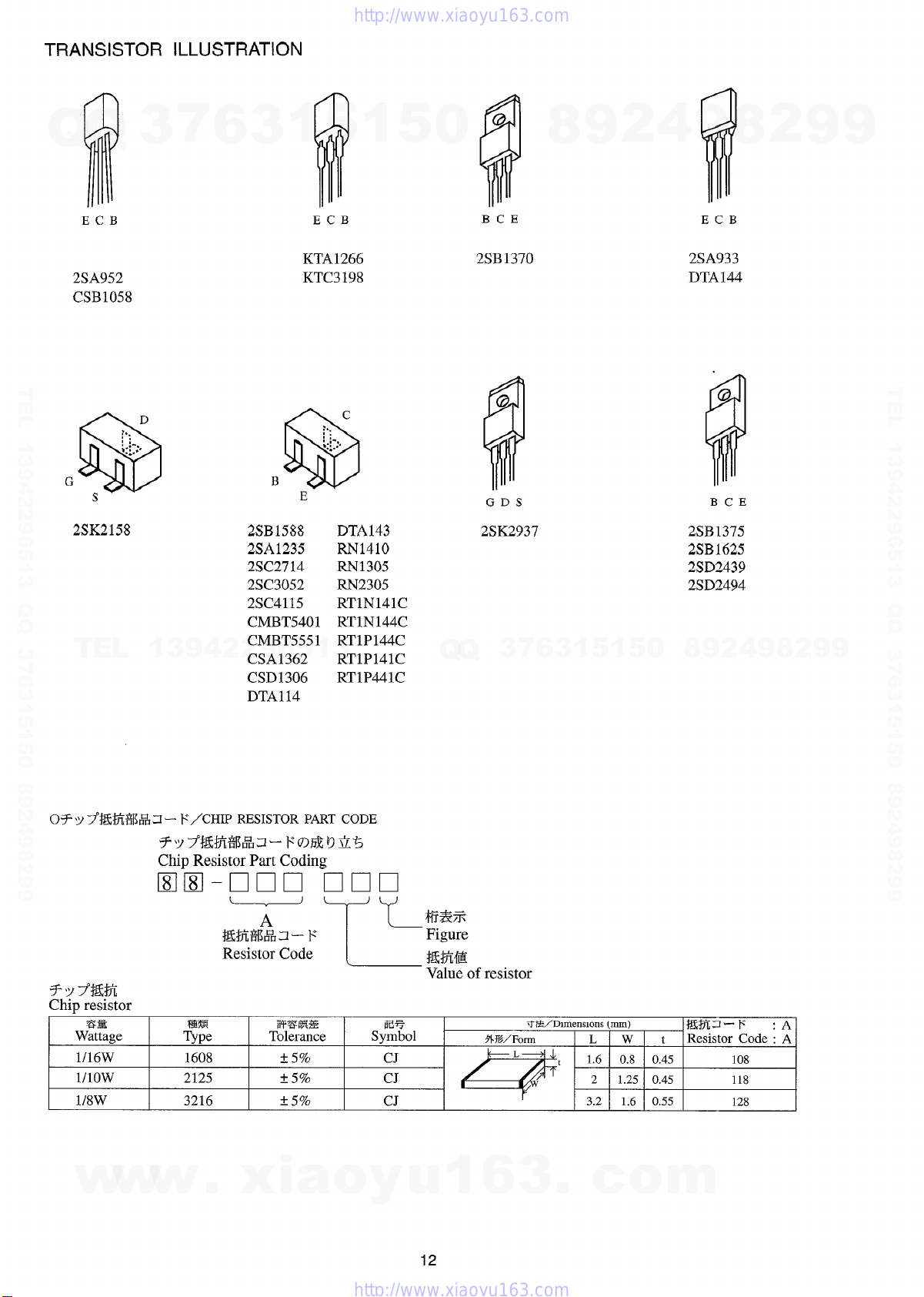
TRANSISTOR ILLUSTRATION
7
Q
Q
2SA952
CSB1058
TEL 13942296513 QQ 376315150 892498299
G
$iii3
s
2SK2158
TEL
3
D
~.
: :-,
*:1..’
13942296513
6
1
5
f
:,.
: ~.,
%“’
DTA143
RN141O
RN1305
RN2305
RT1N141C
RT1N144C
RT1P144C
RT1P141C
RT1P441C
1
c
3
ECB
KTA1266
KTC3198
B
$iiii3
E
2SB1588
2SA1235
2SC2714
2SC3052
2SC4115
CMBT5401
CMBT5551
CSA1362
CSD1306
DTA114
5
0
Q
Q
BCE
2SB1370
GDS
2SK2937
3
7
8
6
3
9
1
5
2
1
5
4
0
9
iii
ECB
2SA933
DTA144
BCE
2SB1375
2SB 1625
2SD2439
2SD2494
9
8
8
2
4
2
9
8
9
2
9
9
TEL 13942296513 QQ 376315150 892498299
9
07 Y 7°#3tfi%~ Z – F/CHIP RESISTOR PART CODE
F’Y7”$&%i%!?12- Fomomb
Chip Resistor Part Coding
❑ m-non ❑ 00
ZsB
Wattage T~~e
1116W 1608
1I1OW
l/8W
w
w
w
M%%IH3–– F
Resistor Code
2125
3216
.
(
A
“’L
~g-~~
Tolerance
* 5y~
f 5q~
* 5%
xia
o
L
Em%
Symbol
CJ
CJ
CJ
y
m?%
Figure
W?ifizi
Value of
u
12
e
1
resistor
%%/Form
6
L
3
7T%’’D1mens1ons (mm)
L w t
1.6
t
3.2 1.6 0.55
.
2
c
#J7t3- F
Resistor Code : A
0.8 0.45
1.25 0.45 118
o
m
:A
108
128
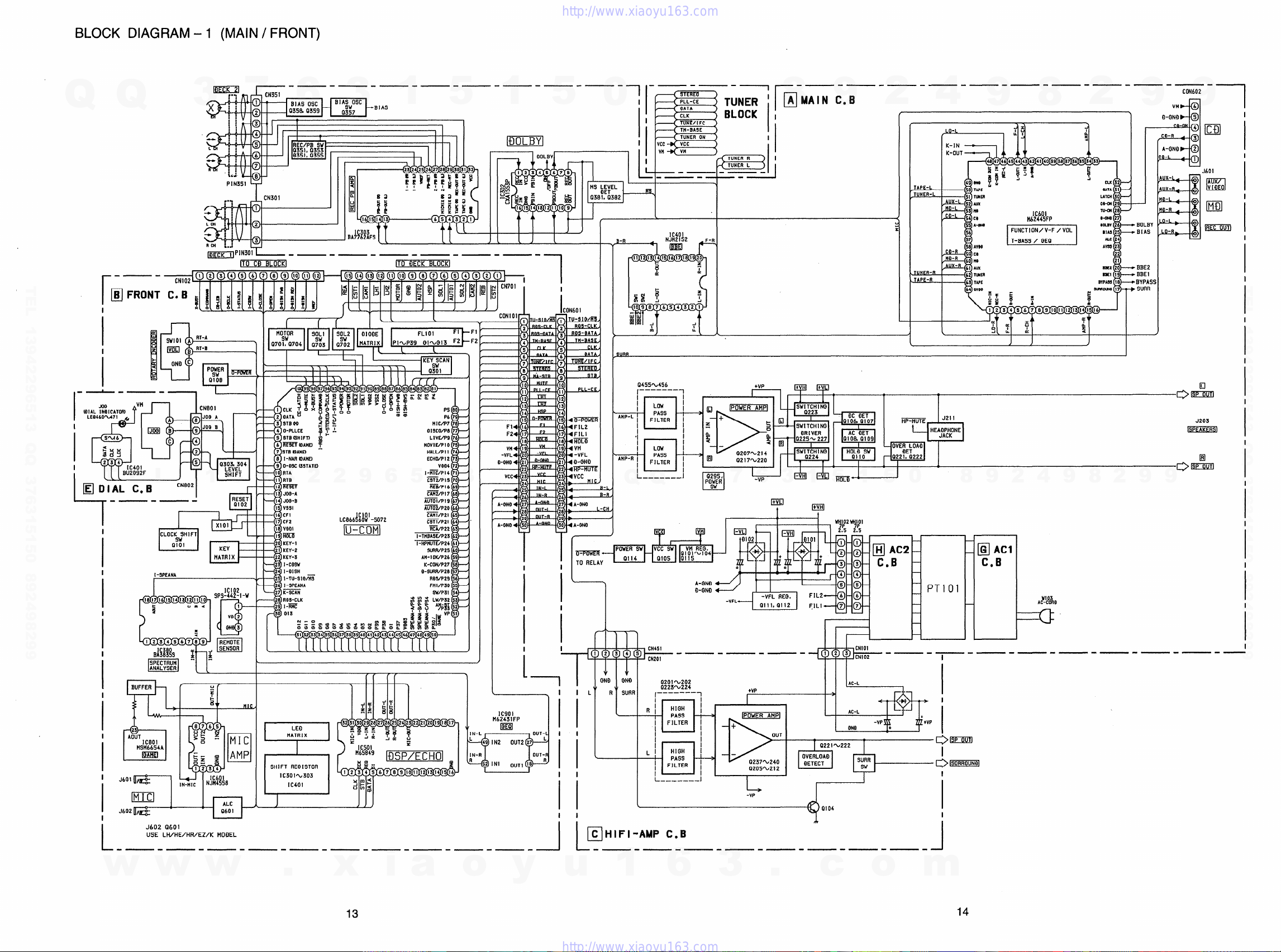
BLOCK DIAGRAM -1 (MAIN/ FRONT)
—. —. —- —- —. —- —- —. —- —,-— -— -—
-L CN351
7
@
@
‘“’ Y-_- —- —- —-—-——
ITO CO BLOCK[ ITO flECK BLOCKI
Ill
3
9
ff~:~
ti
El
6
4
I&uCEn ~~i
5
RFEKft?ANEl~
h
9TBi3AH0
7
I-NAR 03AN31
6
O-osc (3STAT0
9
RTA
10
II R7D
4
2
12 R’mT
13 JOO-A m@P17 68
14 JOO-B ~/P19 b7
Is Vssl
3
BIAS
t
2
9
6
CN802
3
flu!
[-] P1N301
1
Q
TEL 13942296513 QQ 376315150 892498299
I
I
I
L
Q
B FRONT
In
I
@l
L
T
l’EJDIAL c.B
E
-—- —-
I
I
L
m
I
I
I
I-3PEAMA
8
.m4
1
5
5
o19co/P8 77
LlV3/P9 76
m-i
?5:E L
W-IS 70
1
3
iiwP16 69
A~i/P20 66
I/a
-—- —-— -—- —-— -—- —-— -—-
1
5
0
I
t
I
I
i
L+
-—- .
-—
BLOCK I ;
TUNER R
TUNER L
EJ
.—.
—-
_-l
II
—
8
I
I
9
2
4
9
8
2
9
I
CON602
Vdal
O-WO 5
CD-R
=$I?)
—id
-R
a
O-L
4
9
—
4 ml
3
ml
mmm
*
I
I
I
I
I
1
I
I
I
A~ON601
— .,, .,,l, m
}
r{s
F2+
I
Vn*
-VFL 4
O-ONO4
s,,, ,,”
Vcc
A-ONO
I
ST
TE
F’
0455%456
.—-——- —
I
1
I
l—
~, ……. , ~
l––-_____J
Q
Q
i
+VP
mm
J211
F
HE$OFIF~ONE
D
J203
a
J
Q295,
3
PO$ER
•1
7
I
-VP
6
m!mi!kml
I
I
dnti
3
1
1
T
~—1—_——J
5
1
I
1
1
5
0
1
9
2
8
9
4
2
9
8
9
oEimi3
.
I
H
II
II
I
H
1
=,’E_
I
I
A—”- —
+
/1 ~lxllxl I II
33
mtlxl
44 u
b.D
PT 01
II
@ AC1
C.B
1
TEL 13942296513 QQ 376315150 892498299
I
I
I
I
I
I
I
I
I
I
i
I
I
m
I
BUFFER
1
z=
23
I
AOUT
1C801
KNf6654A
l!!%
I
J601 oAy-&
m
I
.16021-
I
I
L. —.— — —- —-— -— -—-— -—-—.
w
J602 (3601
USE LH/HE/HR/EZ/K MOQEL
w
8765
u
LJi>> E
0
c.
2E
1234
a
4 N\i&i8
lN-MIC
w
MIC
AMP
❑
ALC
Q60I
SH1FT RE131STOR
IC301%303
m
J
.
IC401
x
i
a
J
! f
IN-L
IN-R
o
lc901
M62431FP
m
y
H
1
I
I I
‘1 I
I
I
I
I
u
+-m
x-l-i
L
W-–-–-–-T+’
GNFI mf)
\ t Q225%224
SIJRR
IL
I
I
I
h—l
L
R
\
C HIFI-AMP C.B
-—- —-— -—- —-— -—- —-
1
R[
LI
\
0201%202
,–––– —I
HIOH ~
PASS
I
FILTER I
i
%
I
I
I
HIGH I
PASS +
I
FILTER ,
]
i_.-–____l
6
— +
3
+VP
0205’%212
L
-VP
.
1
I
1-
I
/
I
I
‘ 2 3 CNI02
AC-L
AC-L
(N+O
OETECT
Q104
A
c
CNIO1
-—-—-—-—-—-—.—-—-
I
I
I
-VP
I
I
I
d
o
m
14
I
I
4 5
6
3
.
Q
2
I
1 1
1 “1
—
Q
Lm
TEL 13942296513 QQ 376315150 892498299
3
3
7
1
6
5
1
7
5
8
0
12
4
FROM
❑ HEAD-1 C.B
TO PIIN301
9
11
2
9
10
8
FROM ❑ HEAf)-2 C-B
Tn P1N351
13 14
9
8
2
9
9
TEL 13942296513 QQ 376315150 892498299
T
E
L
1
3
9
4
2
2
9
6
5
1
3
Q
Q
3
7
6
3
1
5
1
5
0
8
9
2
4
9
8
2
9
9
w
w
w
.
15
x
i
a
o
y
u
1
6
3
.
c
o
m
16
Loading…
FAQ: Types of Manuals and Their Contents
Aiwa NSX-F959 Manuals come in various types, each serving a specific purpose to help users effectively operate and maintain their devices. Here are the common types of Aiwa NSX-F959 User Guides and the information they typically include:
- User Manuals: Provide comprehensive instructions on how to use the device, including setup, features, and operation. They often include troubleshooting tips, safety information, and maintenance guidelines.
- Service Instructions: Designed for technicians and repair professionals, these manuals offer detailed information on diagnosing and repairing issues with the device. They include schematics, parts lists, and step-by-step repair procedures.
- Installation Guides: Focus on the installation process of the device, providing detailed instructions and diagrams for proper setup. They are essential for ensuring the device is installed correctly and safely.
- Maintenance Manuals: Provide guidance on routine maintenance tasks to keep the device in optimal condition. They cover cleaning procedures, part replacements, and regular servicing tips.
- Quick Start Guides: Offer a concise overview of the essential steps needed to get the device up and running quickly. They are ideal for users who need immediate assistance with basic setup and operation.
Each type of Aiwa NSX-F959 instruction is designed to address specific needs, ensuring users have the necessary information to use, maintain, and repair their devices effectively.
Related Instructions for Aiwa NSX-F959:
1
XR-H1100
Service manual #YJZZ82: XR-H1100 Stereo System Service manual
26
442
84
4
AV-D58
Operating instructions manual Aiwa Stereo Receiver Operating instructions manual (File: aiwa-av-d58-operating-instructions-manual-98, 25/02/2025)
98
986
158
6
HS-RX418
Service manual Aiwa Cassette Player Service manual (File: aiwa-hs-rx418-service-manual-16, 11.12.2024)
16
1408
338
8
NSX-S16
Service manual Aiwa Stereo Receiver Service manual (File: aiwa-nsx-s16-service-manual-4, Sat 02.2025)
4
653
118
10
CSD-EX180
Service manual CSD-EX180 (Cassette Player ePDF Manual, #ZN33TU)
14
383
73
Stereo System Devices by Other Brands:
|
LG CM4550 Simple Manual Stereo System #1ZR8O9 Mini Hi-Fi System 05 Apr 2025 | 4 |
|
|
Panasonic SC-HTE80 Quick Start Manual SC-HTE80 (Home Cinema speakers ePDF Manual, #J59P69) Quick Start Guide 03 Dec 2024 | 2 |
|
|
Sony HCD-HPX9 — Hi Fi Components Service Manual HCD-HPX9 — Hi Fi Components (Stereo System ePDF Manual, #EBJ3BD) SERVICE MANUAL 14 Feb 2025 | 108 |
|
|
LG MCD112 Service Manual LG MCD112 Manual (Service manual), @GBW28M MINI Hi-Fi SYSTEM 26 Dec 2024 | 65 |
Categories:
Receiver
Portable Radio
Stereo System
Wireless Headphones
Stereo cassette receiver
Stereo radio receiver
Document Download |
‹
›
Aiwa NSX-F959 Manual Online:
3.25,
2492
votes
Aiwa NSX-F959 User Manual
Aiwa NSX-F959 User Guide
Aiwa NSX-F959 Online Manual
Text of Aiwa NSX-F959 User Guide:
Related Products and Documents (Stereo System):
-
Aiwa CSD-EX151 Stereo System Operating instructions manual
CSD-EX151
aiwa/csd-ex151.pdf, 20 -
Aiwa XH-A1000 Stereo System Operating instructions manual
XH-A1000
aiwa/xh-a1000.pdf, 101 -
Aiwa XR-EM50 Stereo System Operating instructions manual
XR-EM50
aiwa/xr-em50.pdf, 20 -
Aiwa NSX-MT520 Stereo System Operating instructions manual
NSX-MT520
aiwa/nsx-mt520.pdf, 32 -
Aiwa XR-EM220 Stereo System Operating instructions manual
XR-EM220
aiwa/xr-em220.pdf, 32 -
Aiwa NSX-AK772 Stereo System Service manual
NSX-AK772
aiwa/nsx-ak772.pdf, 46 -
Aiwa NSX-D77 Stereo System Operating instructions manual
NSX-D77
aiwa/nsx-d77.pdf, 27 -
Aiwa Z-L900 Stereo System Service manual
Z-L900
aiwa/z-l900.pdf, 43
Comparable Devices:
| # | Manufacturer | Model | Document Type | File | Updated | Pages | Size |
|---|---|---|---|---|---|---|---|
| 1 | Siemens | KI..N series | User manual manual | siemens/kin-series-1KN.pdf | 09 Dec 2024 | 26 | |
| 2 | ADC | Adimals 426 | Manual | adc/adimals-426-89O.pdf | 06 Nov 2023 | 4 | |
| 3 | Dynex | DX-37L200A12 | Product specifications | dynex/dx-37l200a12-3C6.pdf | 02 Feb 2025 | 1 | 0.7 Mb |
| 4 | Datalogic | QuickScan Lite QW2100 | Product reference manual | datalogic/quickscan-lite-qw2100-B4X.pdf | 17 Jan 2025 | 324 | |
| 5 | Lenovo | G470 4328 | Specifications | lenovo/g470-4328-M8U.pdf | 02 Jan 2024 | 1 | |
| 6 | Cisco | DX650 | Operation & user’s manual | cisco/dx650-9VO.pdf | 24 Jul 2024 | 6 |
Similar Resources:
Stereo System Instructions:
-
Sharp LCD TV TU-GA1U-S
Sharp LCD TV Parts list (File: sharp-tu-ga1u-s-lcd-tv-33, Saturday 14-12-2024)
TU-GA1U-S, 33
-
Olympus Printer P-330 — Digital Home Photo Printer
Olympus P-330 — Digital Home Photo Printer Guide (Doc Type: Printer Installation manual)
P-330 — Digital Home Photo Printer, 79
-
Oakton Oven StableTemp
Oakton StableTemp Guide (Doc Type: Oven Operating instructions manual)
StableTemp, 8
-
Sven Keyboard standard 310 combo
Sven standard 310 combo User Guide (Doc Type: Keyboard Operation & user’s manual)
standard 310 combo, 4
-
Cannon Wood stove CAWDFS12
Cannon Product User Manual: CAWDFS12 PDF Use, care and installation instructions — 5JW61O
CAWDFS12, 16
-
GE Dryer GTD72GBPNDG
GE GTD72GBPNDG User Guide (Owner’s manual), @8E9O56
GTD72GBPNDG, 32
-
Toshiba DVD Player RD-XS35
DVD Player #TBFX5M
RD-XS35, 2
-
Clarion DVD Player VZ709E
Owner’s manual & installation manual for Clarion VZ709E DVD Player
VZ709E, 84
-
Kramer Switch VS-311HDMI
Switch Operation & user’s manual (Kramer VS-311HDMI)
VS-311HDMI, 30
-
Philips Portable DVD Player PET731/12
Philips Portable DVD Player PET731/12 Operation & user’s manual
PET731/12, 29
-
Buick Automobile 1994 Roadmaster
1994 Roadmaster (Automobile ePDF Manual, #JREXCZ)
1994 Roadmaster, 324
-
Santec Security Camera VTC-375IRHG
Security Camera PDF Quick installation manual
VTC-375IRHG, 4
Comments, Questions and Opinions:
Aiwa NSX-F959 Stereo System PDF User Guides and Manuals for Free Download: Found (1) Manuals for Aiwa NSX-F959 Device Model (Service Manual)
Aiwa NSX-F959 Service Manual
Details:
- Manufacturer: Aiwa
- Product Name/ID: Aiwa NSX-F959 / #17418
- Category: Stereo System
- File Path: aiwa/nsx-f959_17418.pdf
- Last Updated: 10 May 2025
- Description: Simplify the use of your Aiwa NSX-F959 with this comprehensive manual, featuring clear installation instructions, detailed operational guidance, and troubleshooting advice for common issues.
- Document Type: User Manual
- Pages: 49
Download PDF
Read Online
The Aiwa NSX-F959 is a compact, all-in-one stereo system that appeals to both audiophiles and casual listeners. With its sleek design and impressive features, this unit has garnered attention as a reliable choice for music enthusiasts. Its combination of CD playback, cassette recording, and AM/FM radio offers a nostalgic yet functional approach to music consumption. In this review, we will delve into the various features of the Aiwa NSX-F959 and the overall performance and user experience it provides.
First and foremost, the sound quality of the Aiwa NSX-F959 stands out. It is equipped with powerful speakers that deliver clear highs and rich lows, making it suitable for various music genres. Users can appreciate the dynamic range and clarity during playback of their favorite tracks. The built-in equalizer allows for customization, enabling users to tweak the sound to their liking. This feature is especially beneficial for those who possess a more refined taste in audio.
Another noteworthy aspect of the Aiwa NSX-F959 is its versatility. This stereo system supports multiple media formats, including:
- CDs
- Cassettes
- AM/FM radio
- AUX input for external devices
This variety ensures that users can enjoy their music library without restrictions. Additionally, the cassette player is a nostalgic touch, allowing users to play or record their favorite mixtapes. The inclusion of AUX input provides flexibility for connecting portable devices, making it a versatile choice for modern users.
When it comes to design, the Aiwa NSX-F959 presents a classic yet modern aesthetic. Its compact size makes it an ideal addition to any room without taking up excessive space. The intuitive interface features a straightforward control panel, making it easy for users of all ages to operate. The display is clear and informative, ensuring that users can see track information and settings at a glance.
Moreover, the build quality of the Aiwa NSX-F959 is commendable. It feels sturdy and durable, which is important for a device often moved around. Users have reported satisfaction with its longevity, indicating that this stereo system is built to last. This durability is matched with a reasonable price point, offering excellent value for the quality provided.
However, it is essential to consider some limitations associated with the Aiwa NSX-F959. While this stereo system shines in many aspects, it lacks Bluetooth connectivity. In today’s digital age, many consumers expect online streaming capabilities and wireless music playback. The absence of these features may deter some potential buyers who prioritize modern conveniences.
In conclusion, the Aiwa NSX-F959 is a well-rounded stereo system that delivers impressive sound quality, versatility, and a classic design. Its array of supported media formats makes it an excellent choice for those who appreciate both modern and nostalgic music experiences. While the lack of Bluetooth may be a downside for some users, the performance and overall features make the NSX-F959 a worthy contender in the compact stereo category. For individuals seeking a reliable audio solution with broad functionality, the Aiwa NSX-F959 is certainly worth considering.
| Manual type: | Service Manual |
|---|---|
| Pages: | 19 |
Page
of
result(s) for ««
×
|
|
NoDevice
Loading…
-
« Previous
Ctrl + ←
-
Next »
Ctrl + →
This manual is suitable for devices
-
AIWA NSX-F959