
Скачать
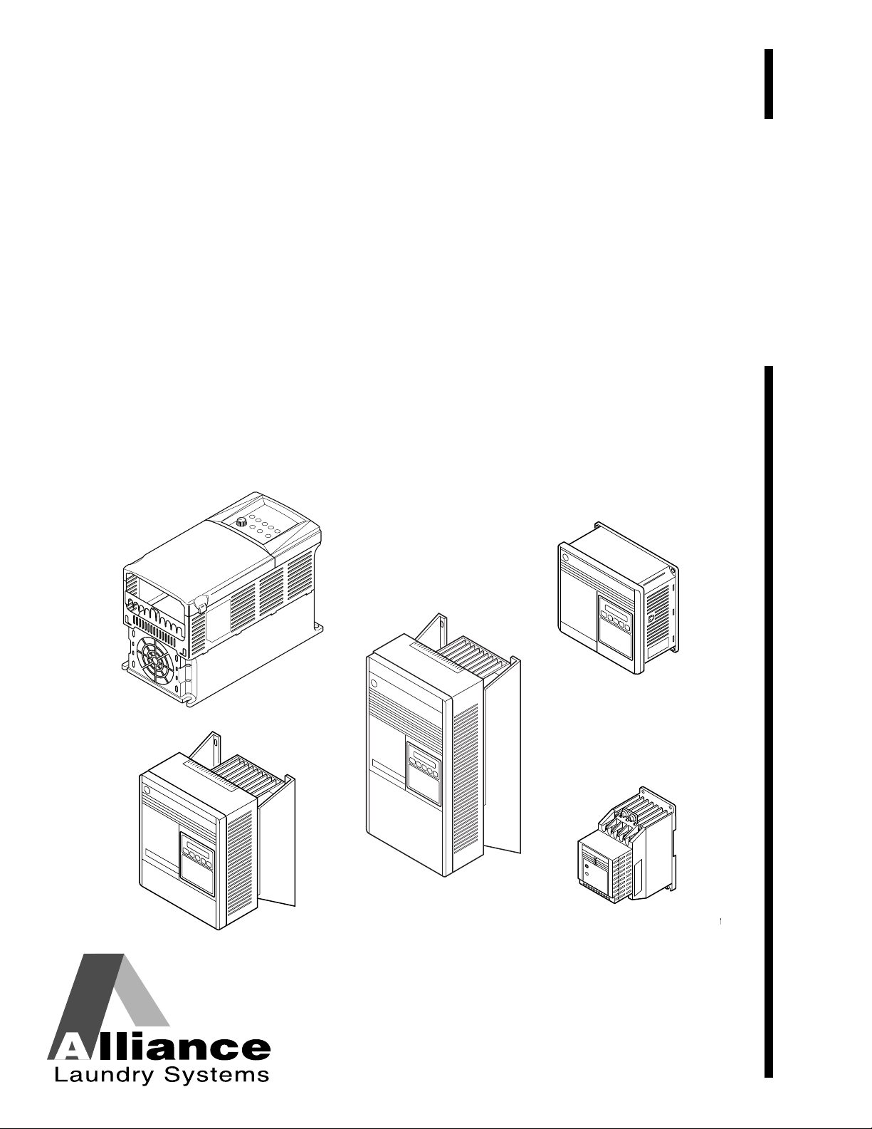
Washer/Extractor
AC Adjustable Frequency
Drive Information
For Allen-Bradley Model Numbers:
160
1305
1336
PowerFlex 40
PowerFlex 400
Part No. F232120R6
January 2010
Supplement
FAULT
READY
U071M
U072M
U073M
U074M
TMB1396C
PHM1396C
U071M
U074M
U072M
U073M
Washer/Extractor
PHM1396C
U071M
U074M
U072M
U073M
AC Adjustable Frequency
Drive Information
For Allen-Bradley Model Numbers:
160
1305
1336
PowerFlex 40
PowerFlex 400
Part No. F232120R6
January 2010


Supplement
Table of
Content s
General Information………………………………………………………………… 3
Nameplate Location…………………………………………………………………… 4
General Inspection…………………………………………………………………….. 5
Storage…………………………………………………………………………………….. 5
PowerFlex 40 and 400 Drive Control Logic………………………………. 6
Installation/Wiring…………………………………………………………………….. 6
Input Power Conditioning………………………………………………………. 6
Electrical Interference……………………………………………………………. 7
Terminal Block Access………………………………………………………….. 8
Power Terminal Block Description …………………………………………. 9
Control Terminal Blocks Description and Control Logic……………. 10
AC Drive Diagnostics/Parameter Viewing……………………………………. 28
PowerFlex Integrated Keypad…………………………………………………. 28
Fault Display and Troubleshooting Information ……………………………. 32
Allen-Bradley Drive Fault Codes ……………………………………………. 33
Troubleshooting Suggestions………………………………………………….. 35
Allen-Bradley 160-Series AC Drives…………………………………………. 36
Installation/Wiring…………………………………………………………………….. 36
Input Power Conditioning………………………………………………………. 36
Electrical Interference……………………………………………………………. 37
Terminal Block Access………………………………………………………….. 39
Power Terminal Block Description …………………………………………. 40
Control Terminal Blocks Description and Control Logic……………. 41
160 Series Drive Control Logic Chart……………………………………… 42
AC Drive Diagnostics/Parameter Viewing……………………………………. 51
160 Program Keypad Module (PKM or Parameter Unit)……………. 51
CopyCat Keypad…………………………………………………………………… 54
Fault Display and Troubleshooting Information ……………………………. 58
Fault Code Identification ……………………………………………………….. 58
Allen-Bradley Drive Fault Codes ……………………………………………. 59
Troubleshooting Suggestions………………………………………………….. 61
Allen-Bradley 1305-Series AC Drives……………………………………….. 62
Installation/Wiring…………………………………………………………………….. 62
Input Power Conditioning………………………………………………………. 62
Electrical Interference……………………………………………………………. 63
Terminal Block Access………………………………………………………….. 64
Power Terminal Block Description …………………………………………. 65
Control Terminal Blocks Description and Control Logic……………. 65
AC Drive Diagnostics/Parameter Viewing……………………………………. 73
Human Interface Module (HIM or Parameter Unit)…………………… 73
HIM Structure Chart – Series A 3.00, Series B 1.01
or Later Versions…………………………………………………………………….. 75
HIM Structure Chart – Earlier Versions……………………………………….. 76
Fault Display and Troubleshooting Information ……………………………. 80
Fault Code Identification ……………………………………………………….. 80
Allen-Bradley Drive Fault Codes ……………………………………………. 81
Troubleshooting Suggestions………………………………………………….. 83
© Copyright 2010, Alliance Laundry Systems LLC
All rights reserved. No part of the contents of this book may be reproduced or transmitted in any form or by any
means without the expressed written consent of the publisher.
F232120
© Copyright 2006, Alliance Laundry Systems LLC – DO NOT COPY or TRANSMIT
1

Supplement
Allen-Bradley 1336-Series AC Drives……………………………………….. 84
Installation/Wiring…………………………………………………………………….. 84
Input Power Conditioning………………………………………………………. 84
Electrical Interference……………………………………………………………. 85
Terminal Block Access………………………………………………………….. 86
Power Terminal Block Description …………………………………………. 87
Control Terminal Blocks Description and Control Logic……………. 88
AC Drive Diagnostics/Parameter Viewing……………………………………. 98
Human Interface Module (HIM or Parameter Unit)…………………… 98
HIM Structure Chart – Series A 3.00, Series B 1.01
or Later Versions…………………………………………………………………. 100
HIM Structure Chart – Earlier Versions…………………………………… 101
Fault Display and Troubleshooting Information ……………………………. 105
Fault Code Identification……………………………………………………………. 105
Allen-Bradley Drive Fault Codes ……………………………………………. 107
Troubleshooting Suggestions………………………………………………….. 109
2
© Published by permission of the copyright owner – DO NOT COPY or TRANSMIT
F232120

General Information
CAUTION
Only personnel familiar with the drive and
associated machinery should plan or
implement the installation, start-up, and
subsequent maintenance of the system.
Failure to comply may result in personal
injury and/or equipment damage.
W659
• This drive contains ESD (Electrostatic
Discharge) sensitive parts and assemblies. Static
control precautions are required when installing,
testing, or servicing this assembly. Component
damage may result if ESD control procedures are
not followed.
• An incorrectly applied or installed drive can
result in component damage or a reduction in
product life. Wiring or appl ication errors, such as
incorrect or inadequate AC supply or excessive
ambient temperatures, may result in malfunction
of the system.
• This drive contains power storage devices that
retain their charge for a time after the removal of
main power. Extreme caution should be used
when working in and around the drive. It is
recommended that main disconnect power to the
drive remain off for three minutes prior to
approaching connections.
General Information
W a rnings specific to a particular subject will appear in
the manual with the discussion of that subject.
F232120
© Copyright, Alliance Laundry Systems LLC – DO NOT COPY or TRANSMIT
3
General Information
FAULT
READY
Nameplate Located on
Exterior of Enclosure
U147ME3A
Nameplate Located
on Bottom Portion of
Chassis Behind Cover
Nameplate Located
on Mounting Plate of
Main Control Board
FRAMES A1, A2, A3, A4
FRAMES B-G
1336 PLUS NAMEPLATE LOCATION
Nameplate Located on
Exterior of Enclosure.
POWERFLEX NAMEPLATE LOCA TION
Nameplate Location
Pertinent drive information used in obtaining
information on drive operation or replacement is
located on the nameplate shown in Figures 1
through 4.
U146ME3A
Figure 1
Nameplate Located on
Exterior of Enclosure
U072ME3
U072ME3A
Figure 2
4
Figure 3
TMB1396C
Figure 4
© Copyright, Alliance Laundry Systems LLC – DO NOT COPY or TRANSMIT
U147ME3A
PHM1396C
F232120

General Information
General Inspection
Upon delivery, verify the item’s nameplate catalog
number against the purchase order.
Before the installation and start-up of the drive, a
general inspection of the mechanical integrity (i.e.,
loose parts, wires, connections, etc.) should be made.
Storage
The drive should remain in its shipping container prior
to installation. If the equipment is not to be used for a
period of time, it must be stored according to the
following instructions in order to maintain warranty
coverage:
• Store in a clean, dry location.
• Store within an ambient temperature range of -40
to 70 degrees C.
• Store within a relative humidity range of 0 to 95
percent.
• Do not store equipment where it could be
exposed to a corrosive atmosphere.
• Do not store equipment in a construction area.
F232120
© Copyright, Alliance Laundry Systems LLC – DO NOT COPY or TRANSMIT
5
PowerFlex 40 and 400 Drive Control Logic
An incorrectly installed system can result in
component damage or reduction in product
life. The most common causes are:
1. Wiring AC line to drive output or control
terminals.
2. EXTERNAL voltage application to control
terminals.
3. Incorrect or inadequate AC supply.
Contact factory for assistance with
application or wiring.
W660
CAUTION
PowerFlex 40 and 400 Drive Control Logic
Installation/Wiring
Input Power Condition Corrective Action
Low Line impedance (less than 1% line reactance)
Greater than 120 kVA supply transformer
Input Power Conditioning
The drive is suitable for direct connection to input
power within the rated voltage of the drive. Listed in
Table 1
cause component damage or reduction in product life.
If any of the conditions exist, as described in Table 1,
install one of the devices listed under the heading
Corrective Action on the line side of the drive.
IMPORTANT: Only one device per branch circuit
is required. It should be mounted closest to the
branch and sized to handle the total current of the
branch circuit.
• Install Line Reactor
• or Isolation Transformer
• or Bus Inductor – 5.5 & 11kW (7.5 & 15 HP) drives
are certain input power conditions which may
only
Line has power factor correction capacitors
Line has frequent power interruptions
Line has intermittent noise spikes in excess of 6000V
(lightning)
Phase to ground voltage exceeds 125% of normal line to line
voltage
Ungrounded distribution system
240V open delta configuration (stinger leg)
(1)
For drives applied on an open delta with a middle phase grounded neutral system, the phase opposite the phase that is tapped in the
middle to the neutral or earth is referred to as the “stinger leg,” “high leg,” “red leg,” etc. This leg should be identified throughout the
system with red or orange tape on the wire at each connection point. The stinger leg should be connected to the center Phase B on the
reactor.
(1)
• Install Line Reactor
• or Isolation Transformer
• Remove MOV jumper to ground.
• or Install Isolation Transformer with grounded
secondary
if necessary
• Install Line Reactor
Table 1
6
© Copyright, Alliance Laundry Systems LLC – DO NOT COPY or TRANSMIT
F232120
PowerFlex 40 and 400 Drive Control Logic
CAUTION
ELECTRIC SHOCK HAZARD! Service and
maintenance to be performed only by an
authorized technician. Disconnect power
before opening any access panels.
W661
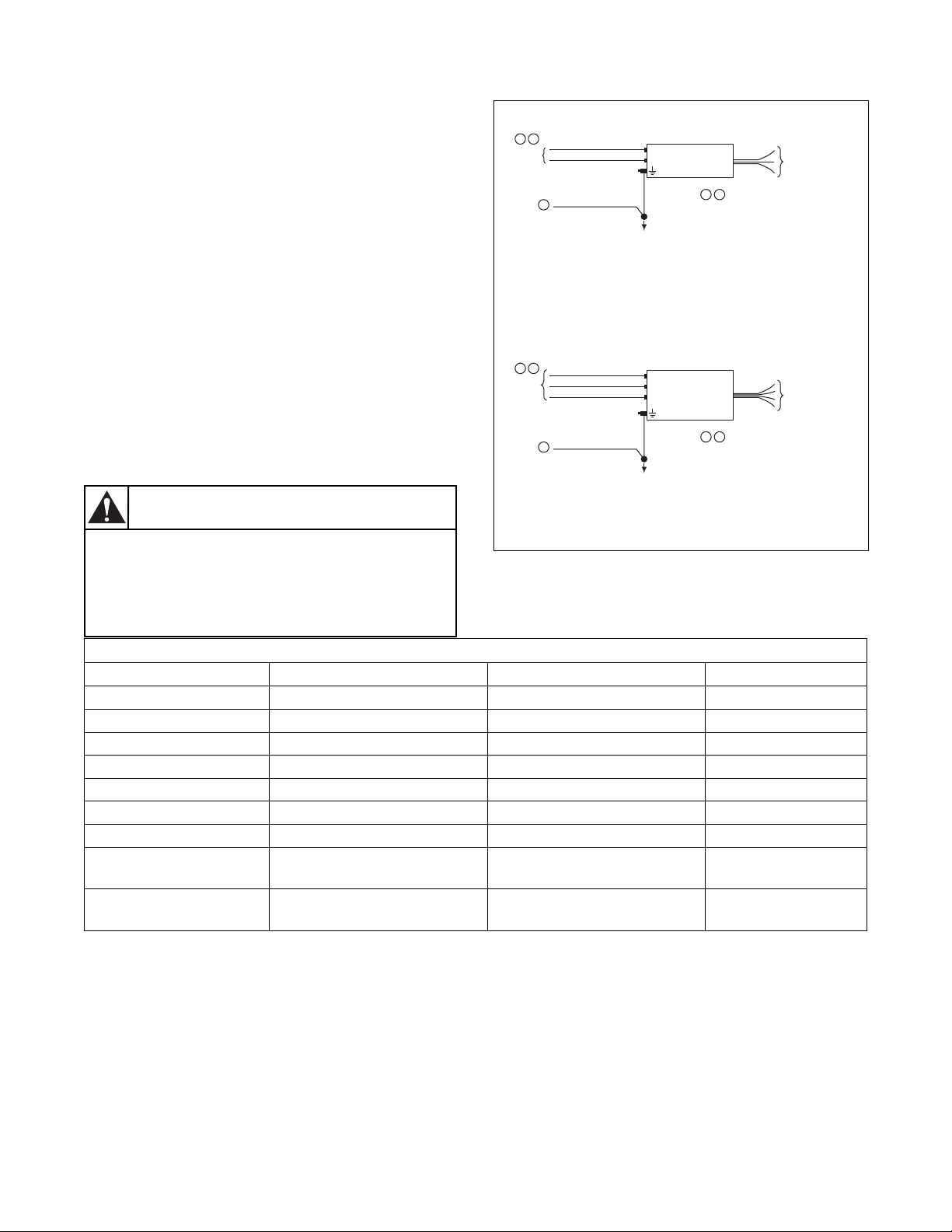
Electrical Interference
EMI
Careful attention must be given to the arrangement of
power and ground connections to the drive to avoid
interference with nearby sensitive equipment. Be sure
to replace all ground connections to their appropriate
locations.
RFI
Drives can be installed with an RFI filter, which
controls high-frequency conducted emissions into the
main supply lines.
Where it is essential that very low emission levels
must be achieved or if conformity with standards is
required, the optional RFI filter may be present.
Figure 5 displays an electrical schematic for various
RFI configurations. Table 2 shows associated RFI
filter part numbers.
1 2
INPUT
POWER
1 2
INPUT
POWER
PROVEN EARTH GROUND
3
PROVEN EARTH GROUND
3
SINGLE PHASE MACHINES
ALLEN-BRADLEY
L1
RFI
L2
WASHING
MACHINE
GROUNDING
TERMINAL
LINE
FILTER
LOAD
2
3
TO AC DRIVE UNIT Ð
GREEN-YELLOW WIRE MUST CONNECT TO
AC DRIVE GROUND TERMINAL.
BLACK WIRES WILL CONNECT TO AC DRIVE
INPUT TERMINALS «R», «S» & «T».
BLACK WIRES ARE NOT LABELED AND THEIR
RESPECTIVE TERMINATION IN AC DRIVE IS
NOT OF IMPORTANCE.
THREE PHASE MACHINES
L1
ALLEN-BRADLEY
L2
RFI
LINE
L3
WASHING
MACHINE
GROUNDING
TERMINAL
FILTER
LOAD
2
3
TO AC DRIVE UNIT Ð
GREEN-YELLOW WIRE MUST CONNECT TO
AC DRIVE GROUND TERMINAL.
BLACK WIRES WILL CONNECT TO AC DRIVE
INPUT TERMINALS «R», «S» & «T».
BLACK WIRES ARE NOT LABELED AND THEIR
RESPECTIVE TERMINATION IN AC DRIVE IS
NOT OF IMPORTANCE.
Figure 5
U166ME3
U166ME3A
RFI Filter Part Number Information
Drive P/N Drive Catalog Machine Voltage Filter P/N
F8044301 and F8168603 22B-B017N104xx 200-240V 50-60Hz 3 phase F8053901
F8044401 and F8168604 22B-D010N104xx 380-480V 50-60Hz 3 phase F8053902
F8044701 and F8168601 22B-B012N104xx 200-240V 50-60 Hz 3 Phase F8053901
F8044901 and F8168602 22B-D6P0N104xx 380-480V 50-60 Hz 3 Phase F8053902
C002501 and F8168701 22B-B024N104xx 200-240V 50-60 Hz 3 Phase F8054001
C002502 and F8168702 22B-D012N104xx 380-480V 50-60 Hz 3 Phase F8054002
C002507 and F8168705 22B-D024N104xx 380-480V 50-60 Hz 3 Phase C002569
C002502, F200309300
22B-B033N104Axx 200-240V 50-60Hz 3 phase F8054001
and F8168703
C002506, F200309400
22B-D017N104Axx 380-480V 50-60Hz 3 phase F8054002
and F8168704
Table 2
F232120
© Copyright, Alliance Laundry Systems LLC – DO NOT COPY or TRANSMIT
7
PowerFlex 40 and 400 Drive Control Logic
WARNING
To reduce risk of electric shock, severe
injury or death, allow machine power to
remain off for three minutes minimum prior
to working in and around AC drive. Proceed
with caution.
W662
POWER TERMINAL BLOCK (TYPICAL)
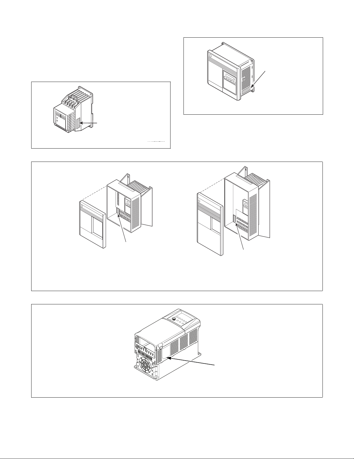
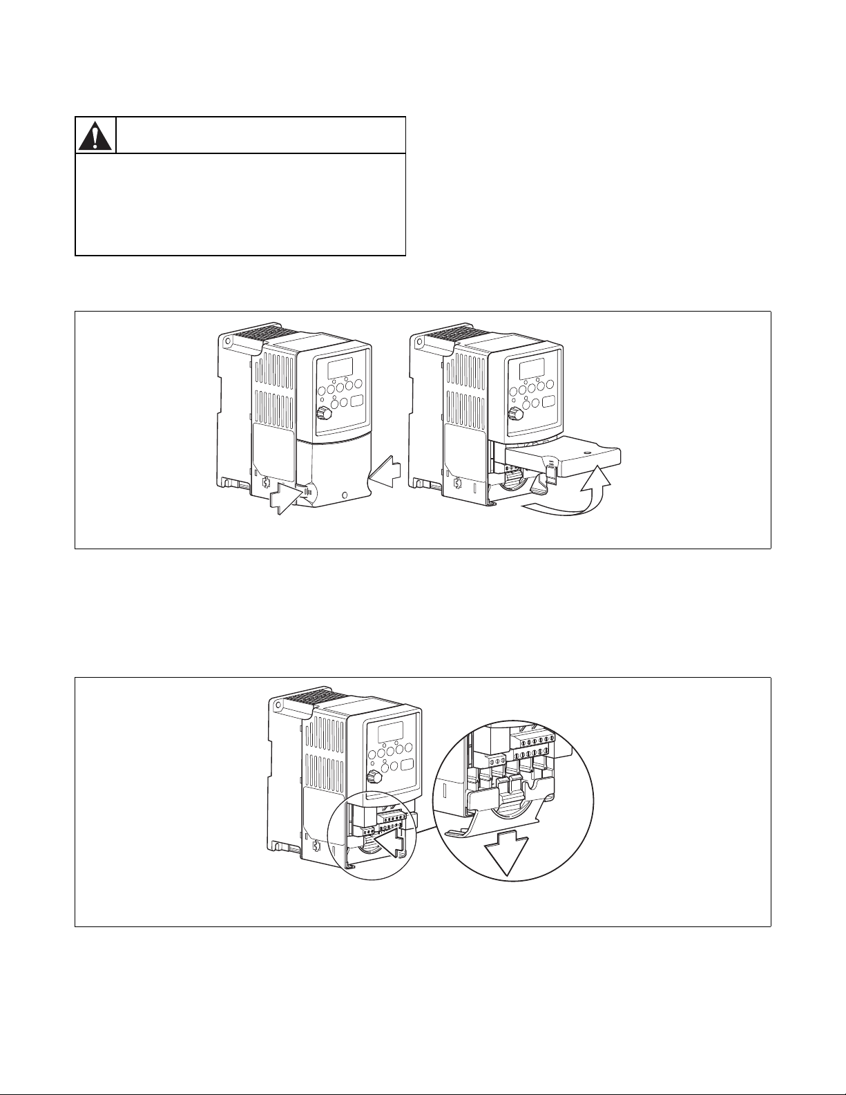
Terminal Block Access
The following information illustrates the terminal
block designations for each of the drive models.
Opening the Cover
1. Press and hold in the tabs on each side of the
cover. Refer to Figure 6.
2. Pull the cover out and up to release.
Power Terminal Block
The drive utilizes a finger guard over the power wiring
terminals. To remove:
1. Press in and hold the locking tab.
PHM636N
Figure 6
2. Slide finger guard down and out. Refer to
Figure 7.
3. Replace the finger guard when wiring is
complete.
PHM637N
8
© Copyright, Alliance Laundry Systems LLC – DO NOT COPY or TRANSMIT
Figure 7
F232120
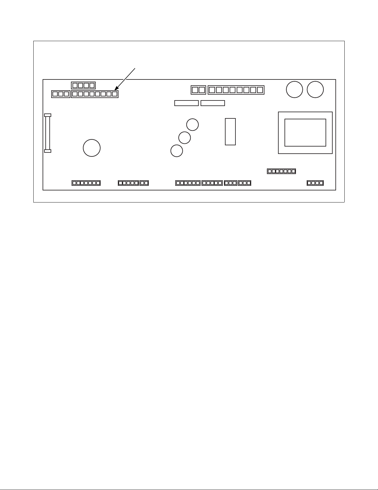
PowerFlex 40 and 400 Drive Control Logic
R/L 1
B Frame
S/L 2 T/L 3 U/T 1 V/T 2 W/T 3
DC- DC+ BR+ BR-
R/L 1
S/L 2
T/L 3
P 1
P 2
DC-
U/T 1
V/T 2
W/T 3
Frame D
Power Terminal Block Description
PowerFlex 40
Input and Output Power Terminals (TB1)
Figure 8
PowerFlex 40
Power Block Terminal (TB1)
Terminal Description
R/L1, S/L2, T/L3 Singl e-phase or
3-phase Power Input
U/T1, V/T2, W/T3 3-phase Motor Output
DC-1, DC+, -DC DC Bus Connection
Ground Connection (PE)
Table 3
PowerFlex 40
PHM741N
PowerFlex 400
Input and Output Power Terminals (TB1)
PHM742N
Figure 9
PowerFlex 400
PowerFlex Power Block Terminal (TBI)
Terminal Description
R/L1, S/L2, T/L3 3-phase Power Input
U/T1, V/T2, W/T3 3-phase Motor Output
P1, P3 DC Bus inductor connection
jumper or Bus inductor must
be present for drive to powerup.
P2, DC- DC Bus Connection
Ground Connection (PE)
Table 5
PowerFlex 400
Power Terminal Block
Torque
Max Wire Size
Min Wire Size
Table 4
1.7-2.2 N-m (16-19 lb-in)
2
5.3 mm
1.3 mm
(10 AWG)
2
(16 AWG)
Power Terminal Block
Torque
Max Wire Size
Min Wire Size
Table 6
5.1N-m (45 lb-in)
33.6 mm
8.4 mm
2
(2 AWG)
2
(8 AWG)
F232120
© Copyright, Alliance Laundry Systems LLC – DO NOT COPY or TRANSMIT
9
PowerFlex 40 and 400 Drive Control Logic
WARNING
To reduce risk of electric shock, severe
injury or death, allow machine power to
remain off for three minutes minimum prior
to working in and around AC drive. Proceed
with caution.
W662
CAUTION
Never permanently jumper the AC drive
balance output terminals or short the wires
in these terminals together. This will
override the balance detection routine and
cause the wash cycle to abort, potentially
causing machine damage or personal injury
in the process.
W671
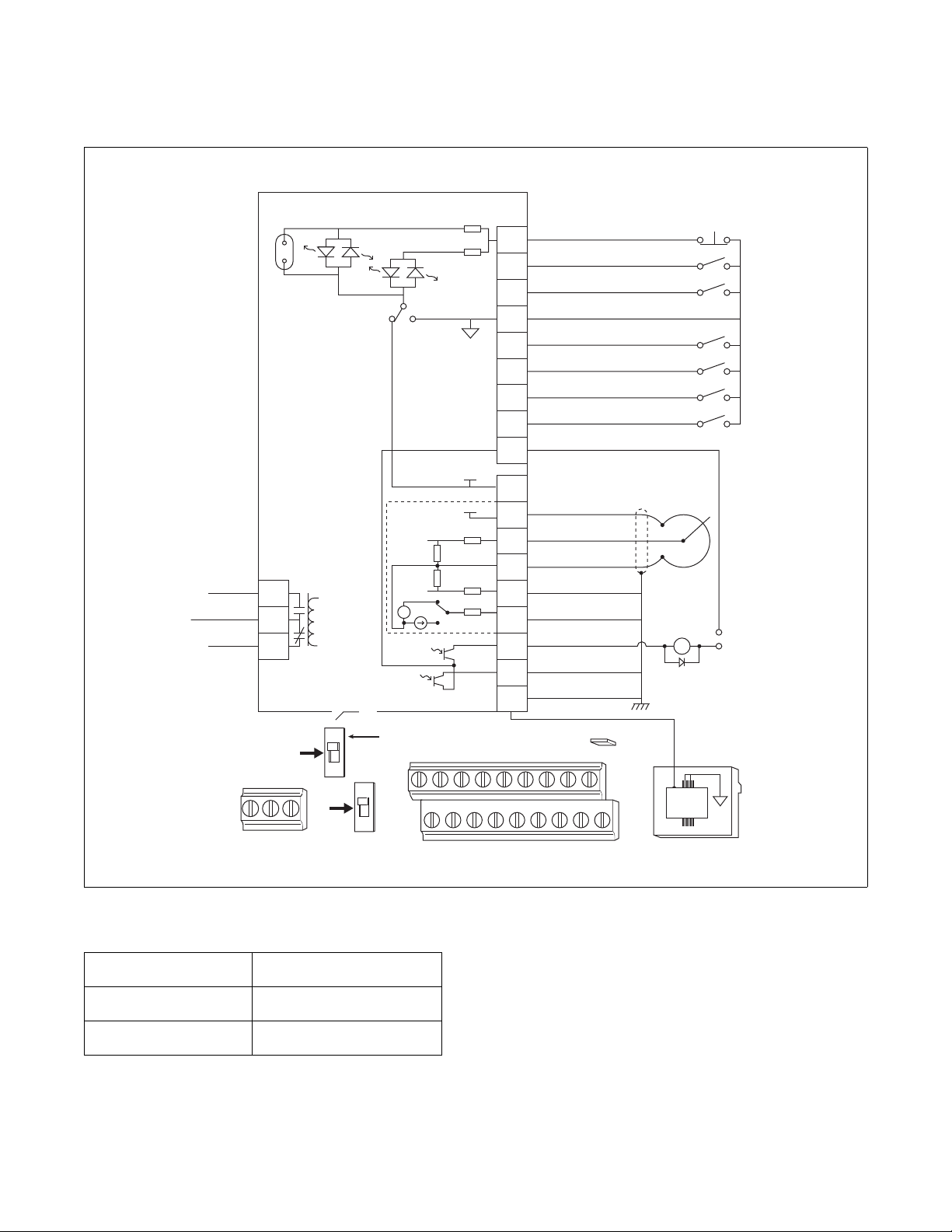
Control Terminal Blocks Description and
Control Logic
NOTE: Do not connect AC drive digital common,
analog common, or common terminals to chassis
ground.
Input Mode Parameter
The control terminal functions are determined in part
by the “Start Source” parameter #36. Changing this
parameter affects the function of some terminals.
Speed Selection
Motor speeds on digitally-controlled AC drives are
controlled by solid state or mechanical switch closure
inputs to Digital In 1, Digital In 2, and Digital In 3
terminals. Similarly, motor rotation direction is
controlled by inputs to Start/Run FWD and Direction/
Run REV terminals. Refer to Figure 10.
An inactive control input terminal (H) will measure
approximately 24v DC while an active control input
terminal (L) will measure less than 1v DC. When a
control input (i.e., Digital In 1, 2, 3, 4, Fwd, Rev, or
Stop) is connected to a common terminal (terminal 4),
the voltage on the control input terminal is reduced to
near zero and the input is activated.
Balance Output
The AC drive balance output signal is transmitted to
the machine controller by the operation of an on-board
normally open relay or transistor. Refer to Figure 10.
The AC drive will analyze the wash load distribution
during certain drain steps and communicate the
severity of load imbalance to the machine controller.
The machine controller then determines if the load is
suitably distributed for the programmed spin speed.
The severity of load imbalance is communicated
digitally by the on-board relay or transistor using a
series of pulses or continuous open or closed state.
Stop/Enable Input
The Stop Input function is machine dependent. The
input is typically used to disable the drive either when
the frame vibration safety limit switch has been
tripped or when the loading door has been opened.
Refer to the applicable machine electrical schematic
for details on the connection of this input. When the
Stop Input signal is interrupted, the control input
signals must be removed and reapplied to restart the
motor operation.
Tables 8 – 14 designate the speed and rotation
direction based on inputs to the control terminals. The
AC drive’ s input status parameters display of 1 s and 0s
at various machine actions can be viewed while
monitoring parameter #13 and/or #14. When the
control input terminal voltage is high (inactive) the
status display will read “0” (logic 0). When the control
input terminal voltage is low (active) the status will
read “1” (logic 1).
10
© Copyright, Alliance Laundry Systems LLC – DO NOT COPY or TRANSMIT
F232120

PowerFlex 40 and 400 Drive Control Logic
Sink/Source Switch
The PowerFlex series of drives include a DIP Switch
that will allow the drive input signals to be wired as
“sink” or “source”. This switch should be set to the
sink mode on all Alliance Laundry equipment made at
the time of this publication. Setting this switch in the
source mode will cause the drive to not operate and be
mistaken as a failed drive.
0-10V/0-20m A Switch
The PowerFlex series of drives include a DIP switch
that will allow the drive analog input signals to be
wired as a 0-10V/0-20 mA switch.This switch should
be set to the 0-10V mode on all Alliance Laundry
Equipment made at the time of this publication.
Setting this switch in the 0-20 mA mode may cause
the drive to not operate and be mistaken as a failed
drive.
Fault Code Display
Refer to Fault Display and Troubleshooting
Information.
F232120
© Copyright, Alliance Laundry Systems LLC – DO NOT COPY or TRANSMIT
11
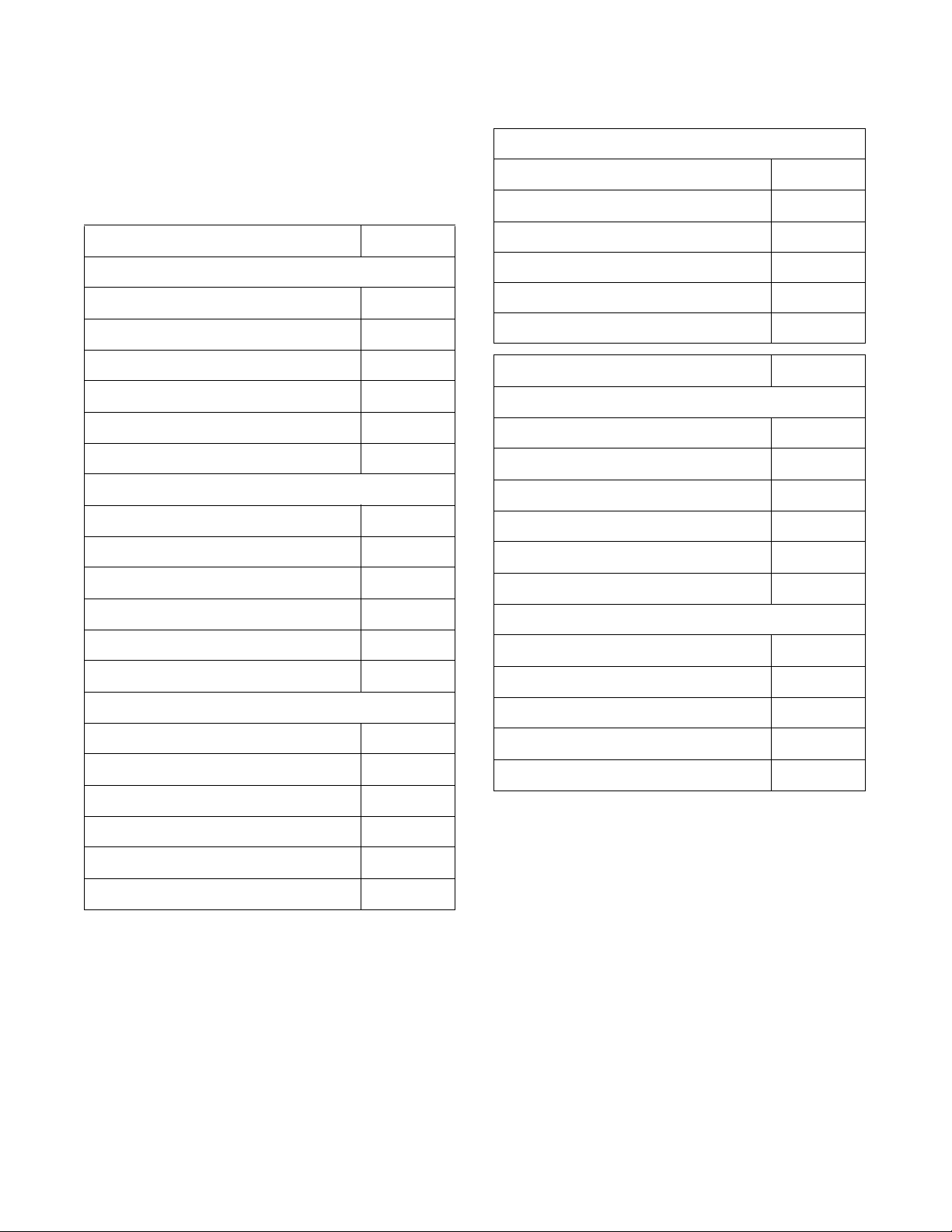
PowerFlex 40 and 400 Drive Control Logic
+
—
18
17
16
15
14
13
12
11
19
19
09
18
08
17
07
16
06
15
05
14
04
13
03
12
02
11
01
R3
R3
ENBL
RS485 Shield
Opto Output 2
Bal Output
Analog Output
4-20mA Input
Analog Common
0-10V ( or ± 10V) Input
+ 10V DC
+ 24V DC
Bal Common
Digital Input 4
Digital Input 3
Digital Input 2
Digital Input 1
Digital Common
REV
FWD
Stop
SNK SRC
+10V
+24V
0-10V
0/4-20mA
30V DC
50mA
Non-inductive
Relay N.O.
Relay Common
Relay N.C.
Pot must be
1-10k ohm
1 Watt Min.
Common
24V
Enable
Jumper
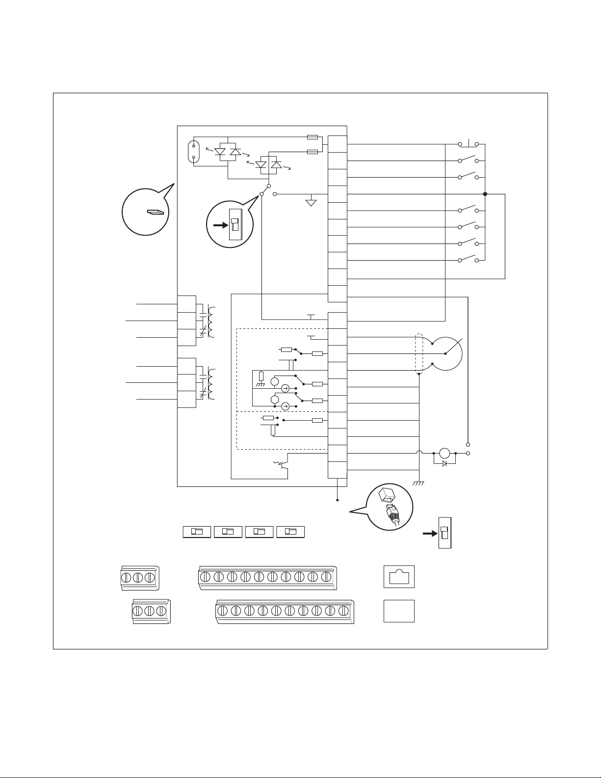
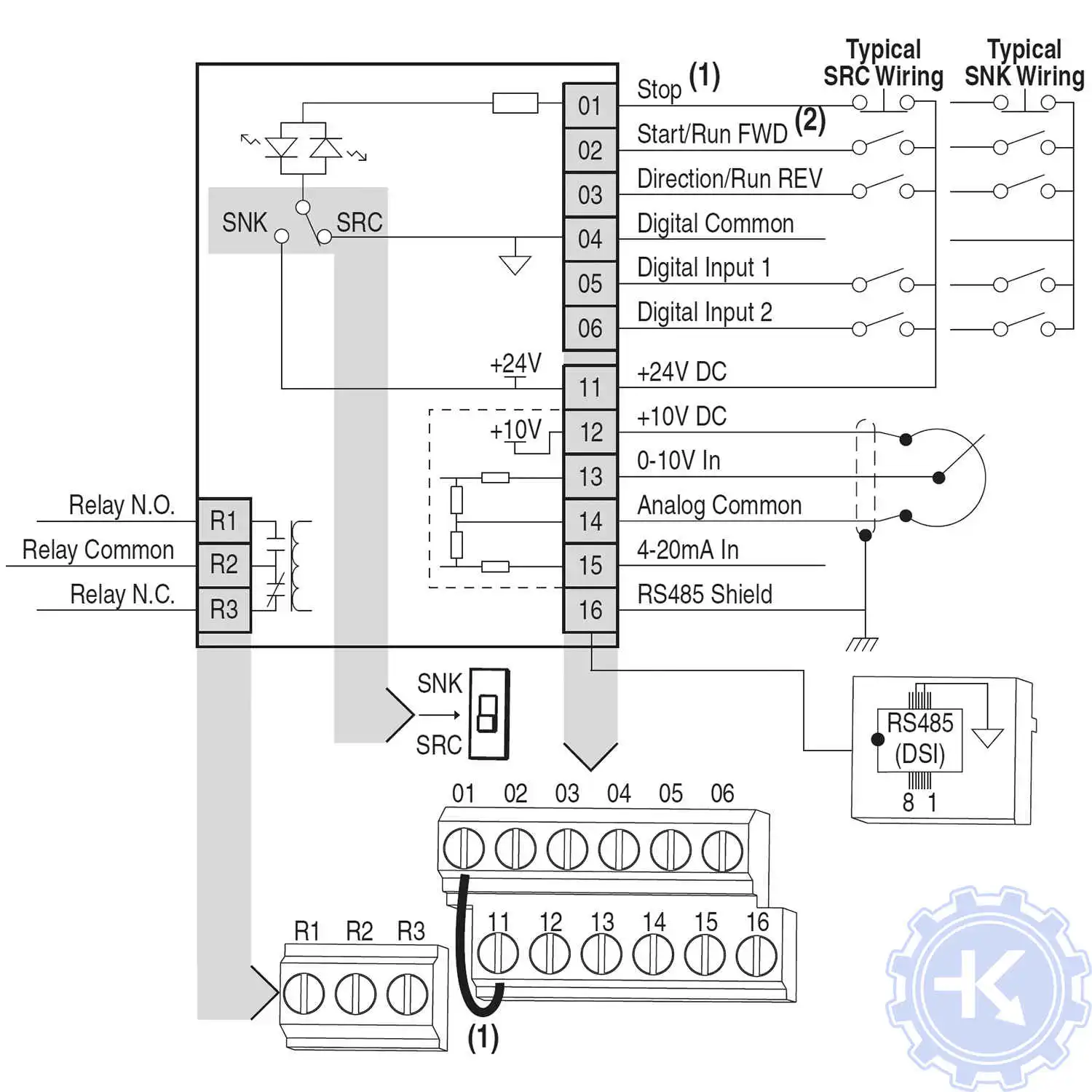
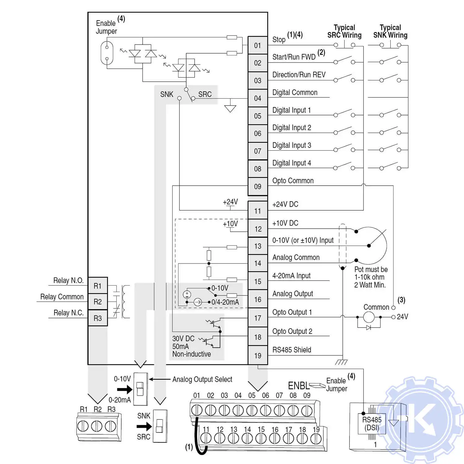
Control Wiring Block Diagram
Enable
Jumper
RS485
(DSI)
0-10V Analog Output Select
0-20mA
SNK
SRC
R2R1
R2
R1
08
07
06
05
04
03
02
01
09
Typical
SNK Wiring
PowerFlex 40 Control Terminal Block
Designations
Control Input/Output Terminal Block
Max Wire Size
Min Wire Size
Torque
0.5-0.8 N-m (4.4-7.0 lb-in)
1.3 mm
0.13 mm
Table 7
2
(16 AWG)
2
(26 AWG)
Figure 10
PHM780N
12
© Copyright, Alliance Laundry Systems LLC – DO NOT COPY or TRANSMIT
F232120
PHM781N
+
—
+
—
0-10V
0-10V
Isolated
18
17
16
15
14
13
12
11
19
20
10090706 080504030201
20191716 181514131211
R6
R3
Opto Output
AS485 Shield
Analog Common 2
Analog Input 2 (AI2)
Analog Output 2 (AO2)
Analog Output 1(AO1)
Analog Common 1
Analog Input 1 (AI1)
+ 10V DC Source
+ 24V DC Source
Opto Common
Digital Common
Digital Input 4
Digital Input 3
Digital Input 2
Digital Input 1
Digital Common
Direction/Run REV
Start/Run FWD
Stop /
Function Loss
1 of 7 Digital Input Circuits
SNK SRC
+10V
0-10V
0-20mA
+24V
0-20mA
30V DC
50mA
Non-inductive
A01
10V 20mA
A02
10V 20mA
AI1
10V 20mA
AI1
RS485
(DSI)
RS485
RS485
10V 20mA
#2 Relay N.O.
#2 Relay Common
#2 Relay N.C.
Pot must be
1-10k ohm
2 Watt Min.
Common
24V
Enable
Jumper
Earth Referenced
Frames D & E
ENBL
Control Wiring Block Diagram
SNK
SRC
R2R1
R6R5R4
R5
R4
R3
#1 Relay N.O.
#1 Relay Common
#1 Relay N.C.
R2
R1
08
07
06
05
04
03
02
01
09
10
Typical
SNK Wiring
SNK
SRC
PowerFlex 400 Control Terminal Block
Designations
PowerFlex 40 and 400 Drive Control Logic
PHM781N
F232120
© Copyright, Alliance Laundry Systems LLC – DO NOT COPY or TRANSMIT
Figure 11
13
PowerFlex 40 and 400 Drive Control Logic
PowerFlex 40 Drive Control Logic Chart
Cabinet Hardmount
“A” control, “B” control, “V” Control and EDC/Netmaster Control
H – Signal Voltage High (approximately 24V DC)
L – Signal Voltage Low (less than 1V DC)
DC Volt Meter Red Probe Terminal Location
DC Volt Meter Black Probe Terminal Location
Digital
In 3
Digital
In 2
07 06 05 01 03 02
04 04 04 04 04 04
Digital
In 1
Stop Rev Fwd
0 = No signal received
1 = Signal received
Digital Input
Status – Parameter
d014
Control Input
Status – Parameter
d013
Action
Idle
1/2 Wash Speed Forward
1/2 Wash Speed Reverse
Wash Speed Forward
Wash Speed Reverse
Distribution Speed
Spin 1
Spin 2
Spin 3
*If digital in 4 is wired to the Forward Input terminal #02, this input will be a “1” whenever the drive receives a forward command. Disregard otherwise.
Cabinet Hardmount
Galaxy control, Quantum control and UniMac Software Control
H – Signal Voltage High (approximately 24V DC)
L – Signal Voltage Low (less than 1V DC)
DC Volt Meter Red Probe Terminal Location
DC Volt Meter Black Probe Terminal Location
Action
Idle
Reduced Wash speed (ccw)
Reduced Wash Speed (cw)
Wash Speed (ccw)
Wash S peed (cw)
Distribution Speed 1 (ccw)
Extract Speed 1 (ccw)
Extract Speed 2 (ccw)
Extract Speed 3 (ccw)
Extract Speed 4 (ccw)
Extract Speed 5 (ccw)
Frequency
Preset
Parameter #
N/A H H H L/H H H 000000/100
71 H H L L H L *10010101
71 H H L L L H 00010110
72 HLHL HL*10100101
72 H L H L L H 00100110
74 LHHL HL*11000101
73 H L L L H L *10110101
76 LLHL HL*11100101
75 L H L L H L *11010101
Frequency
Preset
Parameter #
N/A H H H L/ H H H 000000/100
70 H H H L L H 00000110
70 H H H L H L 00000101
72 H L H L L H 00100110
72 H L H L H L 00100101
71 H H L L L H 00010110
76 L L H L L H 01100110
75 L H L L L H 01010110
73 H L L L L H 00110110
77 L L L L L H 01110110
74 L H H L L H 01000110
Terminal
(SW3)
Digital
Terminal
(SW3)
Terminal
#07
In 3
07 06 05 01 03 02
04 04 04 04 04 04
#07
(SW2)
Digital
Terminal
(SW2)
#06
In 2
#06
Terminal
#05
(SW1)
Digital
In 1
Terminal
#05
(SW1)
Terminal
(Stop)
Stop Rev Fwd
Terminal
(Stop)
#01
#01
Terminal
#03
(STR)
Terminal
#03
(STR)
Terminal
#02
(STF)
Terminal
#02
(STF)
(SW3)
Digital In 3
*Digital In 4
Status – Parameter
*Digital In 4
Digital In 2
0 = No signal received
1 = Signal received
Digital Input
d014
Digital In 3
Digital In 2
Table 8
(SW2)
(SW1)
DB Trans
Digital In 1
Control Input
Status – Parameter
DB Trans
Digital In 1
On
On
Stop
d013
Stop
Rev (STR)
Fwd (STF)
Rev
Fwd
14
© Copyright, Alliance Laundry Systems LLC – DO NOT COPY or TRANSMIT
F232120
PowerFlex 40 Drive Control Logic Chart
Pocket Hardmount — 35 lb through 125 lb Capacity
UniLinc control and M30 control
H – Signal Voltage High (approximately 24V DC)
L – Signal Voltage Low (less than 1V DC)
DC Volt Meter Red Probe Terminal Location
DC Volt Meter Black Probe Terminal Location
Digital
In 3
Digital
In 2
07 06 05 01 03 02
04 04 04 04 04 04
Digital
In 1
PowerFlex 40 and 400 Drive Control Logic
Stop Rev Fwd
0 = No signal received
1 = Signal received
Digital Input
Status – Parameter
d014
Control Input
Status – Parameter
d013
Action
Idle
Reduced Wash Speed (cw)
Reduced Wash Speed (ccw)
Wash S peed (cw)
Wash Speed (ccw)
Distribution Speed (cw)
Extract Speed 1 (ccw)
Extract Speed 2 (ccw)
Extract Speed 3 (ccw)
Extract Speed 4 (ccw)
Extract Speed 5 (ccw)
Pocket Hardmount — 150 Capacity
Terminator control Control
H – Signal Voltage High (approximately 24V DC)
L – Signal Voltage Low (less than 1V DC)
DC Volt Meter Red Probe Terminal Location
DC Volt Meter Black Probe Terminal Location
Action
Idle
Reduced Wash speed (ccw)
Reduced Wash Speed (cw)
Wash Speed (ccw)
Wash S peed (cw)
Distribution Speed (ccw)
Very Low Extract (ccw)
Low Extract (ccw)
Medium Extract (ccw)
High Extract (ccw)
Very High Extract (ccw)
Frequency
Preset
Parameter #
N/A H H H L/ H H H 000000/100
70 H H H L H L 00000101
70 H H H L L H 00000110
72 H L H L H L 00100101
72 H L H L L H 00100110
71 H H L L H L 00010101
76 L L H L H L 01100101
75 L H L L H L 01010101
73 H L L L H L 00110101
77 L L L L H L 01110101
74 L H H L H L 01000101
Frequency
Preset
Parameter #
N/A H H H L/H H H 000000/100
70 H H H L L H 00000110
70 H H H L H L 00000101
72 H L H L L H 00100110
72 H L H L H L 00100101
71 H H L L L H 00010110
76 L L H L L H 01100110
75 L H L L L H 01010110
73 H L L L L H 00110110
77 L L L L L H 01110110
74 L H H L L H 01000110
Terminal
Digital
Terminal
Terminal
#07
In 3
#07
Digital
07 06 05 01 03 02
04 04 04 04 04 04
Terminal
#06
In 2
#06
Terminal
#05
Digital
In 1
Terminal
#05
Terminal
Stop Rev Fwd
Terminal
#01
#01
Terminal
#03
Terminal
#03
Table 9
Terminal
#02
Terminal
#02
Digital In 4
Digital In 3
Digital In 2
0 = No signal received
1 = Signal received
Digital Input
Status – Parameter
d014
Digital In 4
Digital In 3
Digital In 2
On
Stop
DB Trans
Digital In 1
Control Input
Status – Parameter
d013
On
Stop
DB Trans
Digital In 1
Rev
Rev
Fwd
Fwd
F232120
© Copyright, Alliance Laundry Systems LLC – DO NOT COPY or TRANSMIT
15
PowerFlex 40 and 400 Drive Control Logic
PowerFlex 40 Drive Control Logic Chart
Pocket Hardmount
“V” control and “A” control — Designs 7 and 8
H – Signal Voltage High (approximately 24V DC)
L – Signal Voltage Low (less than 1V DC)
DC Volt Meter Red Probe Terminal Location
DC Volt Meter Black Probe Terminal Location
Digital
In 3
Digital
In 2
07 06 05 01 03 02
04 04 04 04 04 04
Digital
In 1
Stop Rev Fwd
0 = No signal received
1 = Signal received
Digital Input
Status – Parameter
d014
Control Input
Status – Parameter
d013
Action
Idle
1/2 Wash Speed Forward
1/2 Wash Speed Reverse
Wash Speed Forward
Wash Speed Reverse
Distribution Speed
Spin 1 Extract
Spin 2 Extract
Spin 3 Extract
*If digital in 4 is wired to the Forward Input terminal #02, this input will be a “1” whenever the drive receives a forward command. Disregard otherwise.
Pocket Hardmount
WE-6 control — Design 5 and Earlier
H – Signal Voltage High (approximately 24V DC)
L – Signal Voltage Low (less than 1V DC)
DC Volt Meter Red Probe Terminal Location
DC Volt Meter Black Probe Terminal Location
Action
Idle
1/2 Wash Speed Forward
1/2 Wash Speed Reverse
Wash Speed Forward
Wash Speed Reverse
Distribution Speed
Medium Extract/Spray Rinse
High 1 Extract
High 2 Extract
High 3 Extract
*If digital in 4 is wired to the Forward Input terminal #02, this input will be a “1” whenever the drive receives a forward command. Disregard otherwise.
Frequency
Preset
Parameter #
N/A H H H L/H H H 000000/100
71 H H L L H L *10010101
71 H H L L L H 00010110
72 HLHL HL*10100101
72 H L H L L Ha 00100110
74 LHHL HL*11000101
73 H L L L H L *10110101
76 LLHL HL*11100101
75 L H L L H L *11010101
Frequency
Preset
Parameter #
N/A H H H L/H H H 000000/100
74 L H L L H H *11000101
74 L H H L L H 01000110
72 H L H L H H *10100101
72 H L H L L H 00100110
71 H H L L H L *10010101
76 L L H L H H *11100101
75 LHHLHL*11010101
73 H L L L H L *10110101
77 L L L L H L *11110101
Terminal
(SW3)
Digital
Terminal
(SW3)
Terminal
#07
In 3
07 06 05 01 03 02
04 04 04 04 04 04
#07
(SW2)
Digital
Terminal
(SW2)
#06
In 2
#06
Terminal
#05
(SW1)
Digital
In 1
Terminal
#05
(SW1)
Terminal
(Stop)
Stop Rev Fwd
Terminal
(Stop)
#01
#01
Terminal
#03
(STR)
Terminal
#03
(STR)
Terminal
#02
(STF)
Terminal
#02
(STF)
(SW3)
Digital In 3
*Digital In 4
Status – Parameter
*Digital In 4
Digital In 2
0 = No signal received
1 = Signal received
Digital Input
d014
(SW3)
Digital In 3
Digital In 2
Table 10
(SW2)
(SW2)
On
(SW1)
DB Trans
Digital In 1
Control Input
Status – Parameter
On
(SW1)
DB Trans
Digital In 1
Stop
d013
Stop
Rev (STR)
Fwd (STF)
Rev (STR)
Fwd (STF)
16
© Copyright, Alliance Laundry Systems LLC – DO NOT COPY or TRANSMIT
F232120
Pocket Hardmount
WE-6 control — Design 6, 7 and 8
H – Signal Voltage High (approximately 24V DC)
L – Signal Voltage Low (less than 1V DC)
DC Volt Meter Red Probe Terminal Location
DC Volt Meter Black Probe Terminal Location
PowerFlex 40 and 400 Drive Control Logic
Digital
In 3
Digital
In 2
07 06 05 01 03 02
04 04 04 04 04 04
Digital
In 1
Stop Rev Fwd
0 = No signal received
1 = Signal received
Digital Input
Status – Parameter
d014
Control Input
Status – Parameter
d013
Action
Idle
1/2 Wash Speed Forward
1/2 Wash Speed Reverse
Wash Speed Forward
Wash Speed Reverse
Distribution Speed
Medium Extract/Spray Rinse
Extract Speed 1
Extract Speed 2
Extract Speed 3 (default)
Extract Speed 3 (maximum)
*If digital in 4 is wired to the Forward Input terminal #02, this input will be a “1” whenever the drive receives a forward command. Disregard otherwise.
Frequency
Preset
Parameter #
N/A H H H L/H H H 000000/100
70 HHHL HL*10000101
70 H H H L L H 00000110
72 HLHL HL*10100101
72 H L H L L H 00100110
71 H H L L H L *10010101
76 LLHLHL*11100101
75 L H L L H L *11010101
73 H L L L H L *10110101
77 L L L L H L *11110101
74 LLHLHL*11000101
Terminal
#07
(SW3)
Terminal
#06
(SW2)
Terminal
#05
(SW1)
Terminal
#01
(Stop)
Terminal
#03
(STR)
Terminal
#02
(STF)
(SW3)
Digital In 3
*Digital In 4
Digital In 2
Table 11
On
(SW2)
Digital In 1
Stop
(SW1)
DB Tran s
Rev (STR)
Fwd (STF)
F232120
© Copyright, Alliance Laundry Systems LLC – DO NOT COPY or TRANSMIT
17
PowerFlex 40 and 400 Drive Control Logic
PowerFlex 40 Drive Control Logic Chart
Cabinet Freestanding
WE-6 control
H – Signal Voltage High (approximately 24V DC)
L – Signal Voltage Low (less than 1V DC)
DC Volt Meter Red Probe Terminal Location
DC Volt Meter Black Probe Terminal Location
Digital
In 3
Digital
In 2
07 06 05 01 03 02
04 04 04 04 04 04
Digital
In 1
Stop Rev Fwd
0 = No signal received
1 = Signal received
Digital Input
Status – Parameter
d014
Control Input
Status – Parameter
d013
Action
Idle
1/2 Wash Speed Forward
1/2 Wash Speed Reverse
Wash Speed Forward
Wash Speed Reverse
Distribution Speed
Medium Extract
High 1 Extract
High 2 Extract
High 3 Extract
*If digital in 4 is wired to the Forward Input terminal #02, this input will be a “1” whenever the drive receives a forward command. Disregard otherwise.
Frequency
Preset
Parameter #
N/A H H H L/H H H 0 0 0 0 0 0/1 0 0
74 LHHL HL*11000101
74 L H H L L H 01000110
72 HLHL HL*10100101
72 H L H L L H 00100110
71 H H L L H L *10010101
76 LLHLHL*11100101
75 L H L L H L *11010101
73 H L L L H L *10110101
77 L L L L H L *11110101
Terminal
#07
(SW3)
Terminal
#06
(SW2)
Terminal
#05
(SW1)
Terminal
#01
(Stop)
Terminal
#03
(STR)
Terminal
#02
(STF)
(SW3)
Digital In 3
*Digital In 4
Table 12
PowerFlex 400 Drive Control Logic Chart
Cabinet Freestanding (250 Model Only)
WE-6 control
H – Signal Voltage High (greater than 10V DC)
L – Signal Voltage Low (less than 1V DC)
DC Volt Meter Red Probe Terminal Location
DC Volt Meter Black Probe Terminal Location
Digital
In 3
Digital
In 2
07 06 05 02 01 03
04 04 04 04 04 04
Digital
In 1
Fwd Stop Rev
0 = No signal received
1 = Signal received
Control Input Status – Parameter d302
Digital In 2
(SW2)
Digital In 1
(SW1)
DB Trans
On
Stop
Rev (STR)
Fwd (STF)
Action
Idle
1/2 Wash Speed Forward
1/2 Wash Speed Reverse
Wash Speed Forward
Wash Speed Reverse
Distribution Speed
Medium Extract
High 1 Extract
High 2 Extract
High 3 Extract
*If digital in 4 is wired to the Forward Input terminal #02, this input will be a “1” whenever the drive receives a forward command. Disregard otherwise.
Frequency
Preset
Parameter #
N/A H H H H L or H H 000000/100
355 L H H L L H 0 *1 1 0 0 1 0 1
355 L H H H L L 00100110
145 H L H L L H 0 *1 0 1 0 1 0 1
145 H L H H L L 00010110
144 H H L L L H 0 *1 0 0 1 1 0 1
357 L L H L L H 0 *1 1 1 0 1 0 1
356 L H L L L H 0 *1 1 0 1 1 0 1
146 H L L L L H 0 *1 0 1 1 1 0 1
358 L L L L L H 0 *1 1 1 1 1 0 1
Terminal
#07
(SW3)
Terminal
#06
(SW2)
Terminal
#05
(SW1)
Terminal
#02
(STF)
Terminal
#01
(Stop)
Terminal
#03
(STR)
Not Used
*Digital In 4
Table 13
18
© Copyright, Alliance Laundry Systems LLC – DO NOT COPY or TRANSMIT
(SW3)
Digital In 3
Digital In 2
Stop
(SW2)
(SW1)
Rev (STR)
Digital In 1
Fwd (STF)
F232120
PowerFlex 40 Drive Control Logic Chart
Pocket Hardmount — IPH, IP and CP Models
PS40 control
H – Signal Voltage High (approximately 24V DC)
L – Signal Voltage Low (less than 1V DC)
Stop Rev Fwd
DC Volt Meter Red Probe Terminal Location
DC Volt Meter Black Probe Terminal Location
01 03 02
04 04 04
PowerFlex 40 and 400 Drive Control Logic
0 = No signal received
1 = Signal received
Control Input Status –
Parameter d013
Action
Idle
Wash Speed Forward
Wash Speed Reverse
Distribution Speed
Low Spin Speed
Medium Spin Speed
High Spin Speed
SmartSpin
NOTE: IPH models use analog signals to control speed — refer to parameter d002 (command f req.) and d020 (analog input %)
to verify speed input signal.
Terminal
Terminal
#01
LHH0100
L H L 0 1 0 1
L L H 0 1 1 0
L H L 0 1 0 1
LHL0101
LHL0101
LHL0101
LLL0111
#03
Terminal
#02
DB Trans
On
Rev
Stop
Table 14
Fwd
F232120
© Copyright, Alliance Laundry Systems LLC – DO NOT COPY or TRANSMIT
19
PowerFlex 40 and 400 Drive Control Logic
COM
X — fmr
RL RM RH STR STF
P/N F370314
V-Computer Output Board
Drive Control
Connections
J8
J2A
30 31 32 33 34 35
J7A
J3B J1
Ribbon
Terminals 1 thru 16
Terminals 17 thru 29
Drive Control
Connections
P/N F370577
WE-6 Output Board
1
7
6
12
H2
H4
H1
H3
H5
Drive
Control
Connections
P/N: 370433 EDC Output Board
Computer Output Boards
Connections identified on these figures set speed and
direction of the drive.
U135ME3A
Figure 12
Figure 13
20
Figure 14
© Copyright, Alliance Laundry Systems LLC – DO NOT COPY or TRANSMIT
U136ME3A
U148ME3A
F232120
PowerFlex 40 and 400 Drive Control Logic
P/N: F8108001 UniLinc Output Board
Drive
Harness
Connection
H13
16 9
81
UNILINC, QUANTUM, GALAXY AND UNIMAC SOFTWARE OUTPUT BOARD
A AND B-CONTROL OUTPUT BOARD
Drive Harness
Connection J11
Figure 15
Figure 16
PHM738N
PHM776N
PHM776N
F232120
© Copyright, Alliance Laundry Systems LLC – DO NOT COPY or TRANSMIT
21
PowerFlex 40 and 400 Drive Control Logic
PS40 CONTROL OUTPUT BOARD
Drive Harness
Connection J11
PHM777N
Figure 17
22
© Copyright, Alliance Laundry Systems LLC – DO NOT COPY or TRANSMIT
F232120
PowerFlex 40 and 400 Drive Control Logic
Control Wire
During troubleshooting, if the wire path between the
control board and the drive is uncertain, refer to
Table 15 for wire connection numbers.
Control Wire Connection Reference Table.
Output Board Terminal
V-Control F370314, F8206501 and F370447-6, etc.
STF
STR
RH
RM
RL
COM
WE-6 Interface Board P/N: F370577, F0370446-xx
J2A-30
J2A-31
J2A-32
J2A-33
J2A-34
J2A-35
EDC – Output Board P/N: F370433
H2-7
H2-8
H2-9
H2-10
02
03
07
06
05
04
04
06
02
07
05
03
07
06
05
04
Table 15 (continued)
UniLinc Control– Output Board F8108001
H13-2
H13-3
H13-4
H13-5
H13-6
H13-7
Output Board Terminal
A and B-Control P/N: F0370448xx
J11-1-8/STF
J11-1-7/STR
J11-1-6/RH
J11-1-5/RM
J11-1-4/RL
J11-1-3/COM
PS40 Main Board P/N: C000281
C12 OV, R-, L-
C12 0-10v
C12 R+
C12 L+
Jumper
Table 15
01, 04, 14
04
07
06
05
03
02
02
03
07
06
03
04
13
02
03
N/A
F232120
H2-11
H2-12
Table 15 (continued)
© Copyright, Alliance Laundry Systems LLC – DO NOT COPY or TRANSMIT
03
02
23

PowerFlex 40 and 400 Drive Control Logic
PowerFlex Drive Parameters
PowerFlex 40
Parameter
Group and
Number
PowerFlex 400 Parameter Group
and Number
Parameter
Description
Function
d001 b001 Output
Frequency
d002 b002 Command
Frequency
Displays instantaneous output frequency
(in Hz).
Displays command output frequency (in
Hz).
d003 b003 Output Current Displays output current (in Amps).
d004 b004 Output Voltage Displays output voltage (in VAC).
d005 b005 DC Bus Voltage Displays DC Bus capacitor voltage (in
VDC).
d006 b006 Drive Status Read from left to right, the four bits
indicate the drive’s condition
(decelerating, accelerating, forward and
running). “0” = false and “1” = true
d007 d307 Fault 1 Code Memory location for the most recent
fault. Refer to Table 20 for a list of most
fault codes. Repetitive faults are stored
only once.
d008 d308 Fault 2 Code Memory location for the 2nd most recent
fault. Refer to Table 20 for a list of most
fault codes. Repetitive faults are stored
only once.
d009 d309 Fault 3 Code Memory location for the 3rd most recent
fault. Refer to Table 20 for a list of most
fault codes. Repetitive faults are stored
only once.
d010 b008 Process Display Not applicable to Alliance Laundry
Systems’ equipment. Refer to the
manual supplied with the PowerFlex
drive for detailed information.
d012 d301 Control Source Read from left to right, the digits
indicate the active source of the Speed
Reference (P038) and Start Source
(P036) command.
d013 d302 Control Input
Status
d014 d302 Digital Input
Status
d015 d303 Communication
Status
Refer to Table 8 throug h Table 14 for
Control Status Input diagnostics.
Refer to Table 8 throug h Table 14 for
Digital Input Status diagnostics.
Not applicable to Alliance Laundry
Systems’ equipment. Refer to the manual
supplied with the PowerFlex drive for
detailed information.
Table 16 (co nt i nu ed )
24
© Copyright, Alliance Laundry Systems LLC – DO NOT COPY or TRANSMIT
F232120

PowerFlex 40
Parameter
Group and
Number
Table 16 (co nt i nu ed )
PowerFlex 400 Parameter Group
and Number
PowerFlex 40 and 400 Drive Control Logic
Parameter
Description
Function
d016 d320 Control
Firmware
Version
Displays the AC drive’s firmware
version. For PowerFlex 40 drives, this
will be 70.xx, 80.xx or 90.xx. For
PowerFlex 400 drives, this will be 14.01.
d017 d321 Drive Type Displays the numeric code of the drive’s
rating (e.g., 4508 = 5hp 200V drive)
d018 b012 Elapsed Run
Time
Displays the accumulated time the drive
has output power. The display is in 10-
hour increments (e.g., a display of 1
represents a value of 10 hours).
d019 d319 Testpoint Data Displays a hexadecimal value of the
“T estpoint Selection” in parameter
A102.
d020 d305 Analog In
(0-10V)
Displays the value (in percentage) of the
voltage at terminal 13(e.g.,
100.0%=10V)
d021 d306 Analog In
(4-20mA)
Displays the value (in percentage) of the
current at terminal 15 (e.g., 0.0%=4mA;
100.0%=20mA)
d022 b010 Output Power Displays the kilowatts present at
terminals U, V and W (in kW).
d023 d318 Output Power
Factor
Displays the angle in electrical degrees
between the motor voltage and the motor
current.
d024 b014 Drive
Temperature
Displays the present operating
temperature (in Celsius) of the drive’s
internal power devices. Refer to Fault
008 in Ta ble 20.
d025 N/A Counter Status Not applicable to Alliance Laundry
Systems’ equipment. Refer to the manual
supplied with the PowerFlex drive for
detailed information.
d026 N/A Timer Status Not applicable to Alliance Laundry
Systems’ equipment. Refer to the manual
supplied with the PowerFlex drive for
detailed information.
d028 N/A Step Logic
Status
Not applicable to Alliance Laundry
Systems’ equipment. Refer to the manual
supplied with the PowerFlex drive for
detailed information.
Table 16 (co nt i nu ed )
F232120
© Copyright, Alliance Laundry Systems LLC – DO NOT COPY or TRANSMIT
25

PowerFlex 40 and 400 Drive Control Logic
Table 16 (co nt i nu ed )
PowerFlex 40
Parameter
Group and
PowerFlex 400 Parameter Group
and Number
Parameter
Description
Function
Number
d029 b013 T orque Current Displays the present value of the motor’s
torque current (in Amps).
d030 N/A OL Level Displays the real-time m oto r overload
progression (100% = F007 Fault).
P041 P041 Reset to Defaults NOTE: This will reset the drive’s
parameters back to the factory-default
values, requiring the AC drive to be re-
programmed. This will not reset A193.
(0 = Not Active; 1 = Reset — Induces
Fault F048).
A101 A198 Parameter Lock Allows parameter modification.
0 = Parameters Unlocked
1= Parameters Locked
See also parameters A192 and A193.
A152 N/A Limited
Frequency
Displays the maximum allowable
frequency (in Hz) based on DC Bus
voltage. The drive output frequency may
be limited due to low input voltage
conditions to alleviate potential motor
stalling.
A164 R261 Balance State Displays the balance detection algorithm
progression (See A187 and A188). (0 =
Algorithm not active; 1 = programmed
pause time; 2 = programmed sample
time; 3 = programmed filter time; 4 =
result obtained)
A187 N/A SmartSpin
Frequency
Displays the commanded SmartSpin
frequency (in Hz) as determined from
Balance Result A188.
A188 R285 Balance Result Displays the numeric value indicating
severity of load imbalance. A balance
result value will be displayed only when
A164 = 4, otherwise the display will be
0.
A192 N/A Parameter
CRC-16
Displays the numeric code culminating
from the value of all of the parameters.
This is intended as a quick reference and
is used to validate the parameter settings
for a specific application.
26
Table 16 (co nt i nu ed )
© Copyright, Alliance Laundry Systems LLC – DO NOT COPY or TRANSMIT
F232120

PowerFlex 40 and 400 Drive Control Logic
Table 16 (co nt i nu ed )
PowerFlex 40
Parameter
Group and
PowerFlex 400 Parameter Group
and Number
Parameter
Description
Function
Number
A193 N/A Counter This counter will increment each time
parameter A192 changes. This is
intended as a quick reference to show if
any parameter has been changed after
factory programming, even if a
parameter was changed and then
restored to the ALS-specified value.
NOTE: The above parameters and descriptions are based on firmware version 90.06 and may differ or be missing
from earlier versions of PowerFlex drive firmware. Refer to parameter d016 for the firmware’s version.
NOTE: All PowerFlex drives used in Alliance Laundry Systems’ equipment are custom-developed with unique
features and parameters. Parameter information provided within the Allen-Bradley PowerFlex series AC drive
manual will differ and may not be relevant.
Table 16
F232120
© Copyright, Alliance Laundry Systems LLC – DO NOT COPY or TRANSMIT
27
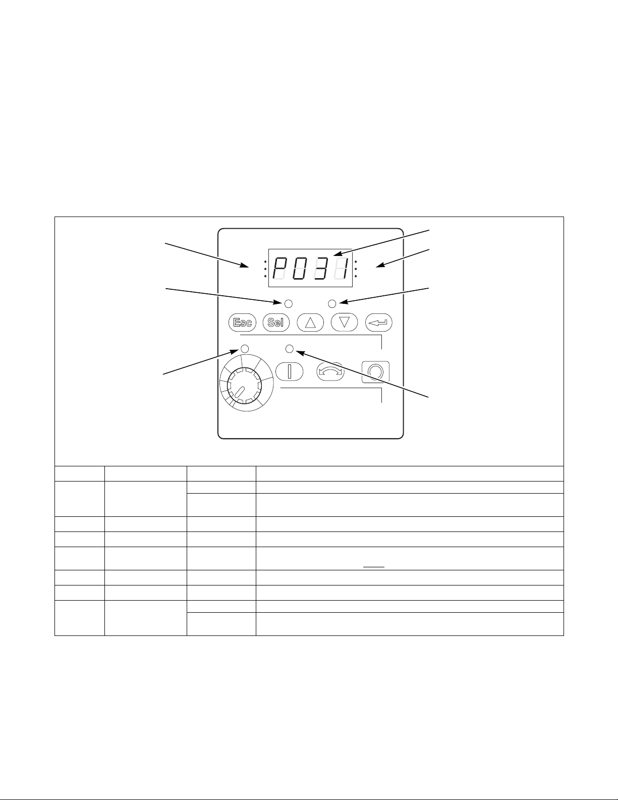
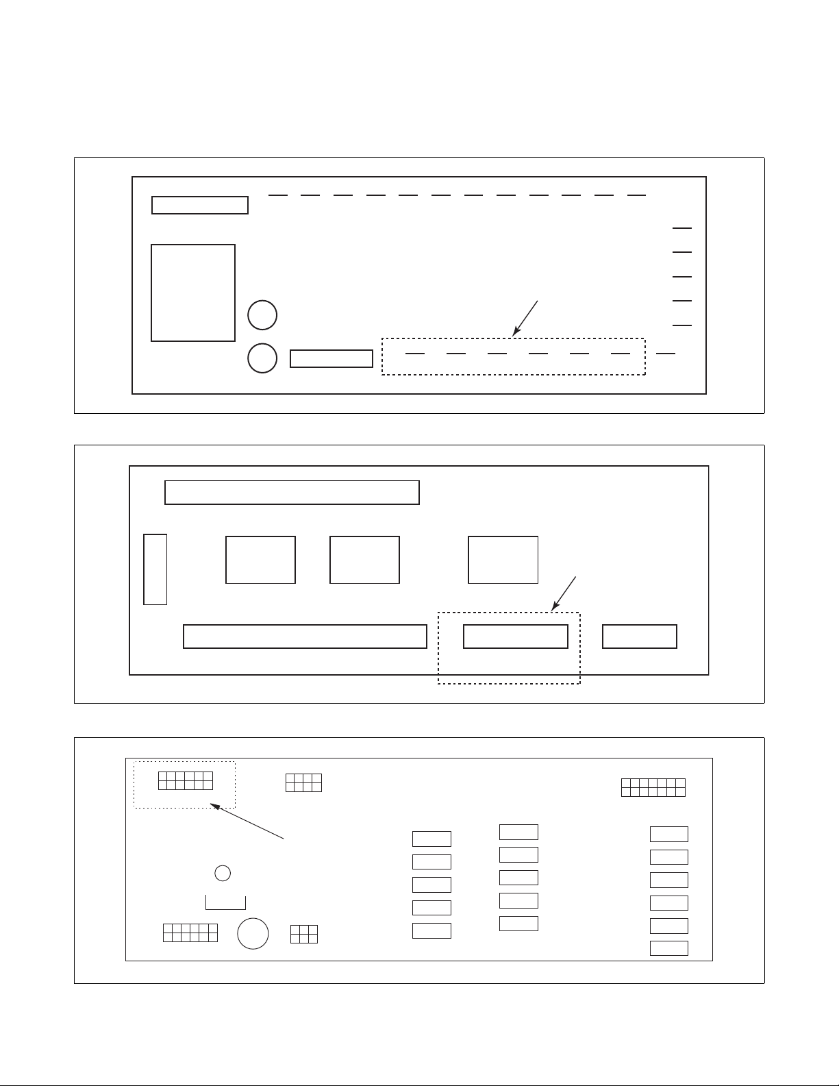
PowerFlex 40 and 400 Drive Control Logic
RUN
FWD
REV
VOLTS
PROGRAM
AMPS
HERTZ
FAULT
POWERFLEX LED DISPLAYS
7
1
4
3
6
2
AC Drive Diagnostics/Parameter
Viewing
PowerFlex Integrated Keypad
The PowerFlex series AC drives have an integral
keypad that can be used for viewing and editing
parameter values. No external parameter unit is
required, however an external hand-held parameter
unit is available (22-HIM-A3) that can provide a userfriendly method of viewing and editing parameter
values in hard-to-access locations.
Integral Keypad
The integral keypad displays several main menu group
selections such as “d”, “P”, and “A” as described
below. Within the Display Group is a fault storage
buffer that stores the last three AC drive fault codes.
Refer to the Fault Display and Troubleshooting
Information Section for more information.
Number LED LED State Description
Display Steady Red Indicates parameter number, parameter value, or fault code.
Flashing Red Single digit flashing indicates that digit can be edited. All digits flashing
indicates a fault condition. See t a b le below.
active unless disabled by A095
Steady Red Indicates drive is running and commanded motor direction.
Flashing Red Drive has been commanded to change direction. Indicates actual motor
direction while decelerating to zero.
1
2
3
4
5
6
7
Displayed Units Steady Red Indicates the units of the parameter value being displayed.
Fault Status Flashing Red Indicates drive is faulted.
Start Key Status Steady Green Indicates Start key on Integral Keypad is active. The Reverse key is also
Pot Status Steady Green Indicates potentiometer on Integral Keypad is active.
Program Status Steady Red Indicates parameter value can be changed.
Run/Direction
Status
Figure 18
PHM640N
(Reverse Disable).
28
© Copyright, Alliance Laundry Systems LLC – DO NOT COPY or TRANSMIT
F232120
Loading…
Ремонт частотного преобразователя Rockwell Automation Allen Bradley Powerflex в Веди
|
|

Ремонт частотного преобразователя Rockwell Automation Allen Bradley Powerflex известного американского производителя промышленной электроники, впрочем, как и ремонт частотников выпущенными под другими брендами имеет ряд особенностей в силу своего конструктива. Частотные преобразователи, точнее их начинка делятся на две части:
- Аппаратная часть,
- Программная часть.
Приводы данного производителя не являются исключением из правил, именно поэтому ремонт частотного преобразователя Allen Bradley имеет точно такой же ряд особенностей, как и у других преобразователей.
Диагностировать ту или иную неисправность помогают коды ошибок частотного преобразователя, которые отображаются на небольшом дисплее, расположенном на лицевой панели частотника.
Ремонт частотных преобразователей Rockwell Automation Allen Bradley Powerflex, впрочем, как и любых других частотников выпущенных под другими брендами всегда начинается с аппаратной части, после успешного ремонта аппаратной части наступает очередь программной.
Настройка частотного преобразователя Allen Bradley прописана в инструкции завода производителя, для каждой серии частотных преобразователей настройка будет индивидуальной, так как каждая линейка преобразователей решает свои собственные задачи, этим обусловливается широкая номенклатура данного промышленного оборудования. Но все же есть определенная последовательность настройки привода, которая относится ко всем частотным преобразователям, любого бренда.
Программирование, настройка частотного преобразователя Allen Bradley
Программирование частотных преобразователей Rockwell Automation Allen Bradley Powerflex (настройка) происходит в рамках установленных производителем правил, существует общий алгоритм по настройке (программированию частотных преобразователей), который относится ко всем производителям данного промышленного оборудования. Ниже представлена пошаговая инструкция по настройке частотных преобразователей Allen Bradley и подобного промышленного оборудования других брендов.

- Выбор режима управления приводом (управление по показанию датчиков, дистанционное управление, дистанционное управление).
- В случае использования отдельного (выносного) монитора, настраивается вывод на него технической информации.
- Далее определяем конфигурацию подключения серводвигателя. На данной стадии задаются такие параметры как- возможность применения обратной связи либо без ее применения, а в память блока заносятся данные по: величине крутящего момента, мощности потребителей, номинальное значения частоты, напряжение, ток и скорости вращения ротора.
- Программируется минимально допустимая величина напряжения и частоты, а также время ускорения ротора от ноля до номинального значения.
- И в завершении, в программу управления частотным преобразователем Allen Bradley вносятся функциональные данные со значениями отдельных клемм и особенностями сигналов. Отмечаются действия оборудования, выполняющиеся автоматически при отсутствии информации поступающей в оперативном режиме с датчика.
В некоторых преобразователях частоты существует пункт наличия/отсутствия фильтра в цепи питания двигателя. Этот пункт отвечает за подключение различных видов нагрузок, в том случае, когда возможно выбрать нормальное или инверсное изменение частоты при повышении уровня сигнала обратной связи.
Ошибки частотного преобразователя Allen Bradley

В процессе работы выходит из строя даже самое надежное промышленное оборудование. Частотники в наше время, нашли широкое применение абсолютно во всех сферах промышленности, управляя как мини моторами в оргтехнике, так и гигантскими двигателями в горнодобывающей промышленности.
Для простоты общения со столь сложной электроникой все частотные преобразователи оснащены небольшими дисплеями с помощью которых выводятся информационные сообщения с кодами ошибок, расшифровав которые можно сразу же узнать причину ее возникновения. Если учесть распространенность данной промышленной электроники, то появляется острая нужда в расшифровке кодов ошибок частотных преобразователей. В этой статье мы рассмотрим одного из самых известных производителей промышленной электроники имеющему уважение во всем мире, Rockwell Automation Allen Bradley и серию частотных преобразователей Powerflex 520.
Существует несколько видов ошибок, некоторые из них можно устранить автоматически, а некоторые возможно исправить только, обратившись в специализированный сервисный центр. В руководстве пользователя прописаны все коды ошибок частотного преобразователя Rockwell Automation Allen Bradley Powerflex 520 и их расшифровка.
Коды ошибок частотного преобразователя Allen Bradley Powerflex 520
Ошибка – это условие, останавливающее преобразователь. Существует два типа аварий.
| Тип | Ошибка | Описание |
|---|---|---|
| 1 | С автоматическим сбросом/запуском | Если произошла ошибка этого типа, а для параметра A541 [Auto Rstrt Tries] установлено значение больше «0», запускается настраиваемый пользователем таймер A542 [Auto Rstrt Delay]. Когда таймер достигает нуля, преобразователь предпринимает попытку автоматического сброса ошибки. И в том случае, если условия, вызвавшего ошибку, больше не существует, произойдёт сброс ошибки и преобразователь снова будет запущен. |
| 2 | Несбрасываемая | Этот тип ошибки может потребовать ремонта преобразователя или двигателя, он может быть вызван неправильным подключением кабелей или допущенными в программе ошибками. Для сброса ошибки необходимо устранить её причину. |
| Поз. | Ошибка | Тип | Описание |
|---|---|---|---|
| F000 | Нет ошибки | — | Ошибка отсутствует. |
| F002 | Дополнительный вход | 1 | Вход внешнего отключения (вспом.). |
| F003 | Потеря питания | 2 | В однофазном режиме обнаружена чрезмерная нагрузка. |
| F004 | Пониженное напряжение | 1 | Напряжение шины постоянного тока упало ниже минимального значения. |
| F005 | Перенапряжение | 1 | Напряжение на шине постоянного тока превышает максимальное значение. |
| F006 | Двигатель заблокирован | 1 | Преобразователь не подходит для разгона или торможения двигателя. |
| F007 | Перегрузка двигателя | 1 | Сработал встроенный электронный ограничитель нагрузки. |
| F008 | Перегрев радиатора | 1 | Температура радиатора/модуля питания вышла за пределы допуска. |
| F009 | Перегрев контр.узла | 1 | Температура модуля управления превышает заданное значение. |
| F012 | Превышение аппаратного тока | 2 | Выходной ток преобразователя превысил допустимый предел. |
| F013 | Ошибка заземления | 2 | Обнаружено замыкание на землю одной или нескольких выходных клемм преобразователя. |
| F015(1) | Потеря нагрузки | 2 | Выходной ток крутящего момента ниже значения, установленного параметром A490 [Load Loss Level], в течение времени, превышающего установленное параметром A491 [Load Loss Time]. |
| F021 | Обрыв фазы вывода | 1 | Обрыв фазы вывода (если включена). Настраивается при помощи A557 [Out Phas Loss En]. |
| F029 | Обрыв аналог. ввода | 1 | Для аналогового входа задано сообщение об ошибке в случае пропадания сигнала. Пропал сигнал. Настраивается при помощи t094 [Anlg In V Loss] или t097 [Anlg In mA Loss]. |
| F033 | Попытки авт. перезапуска | 2 | Предпринятые преобразователем попытки сброса ошибки и продолжения работы оканчивались неудачей столько раз, сколько было задано в параметре A541 [Auto Rstrt Tries]. |
| F038 F039 F040 |
Фаза U на землю Фаза V на землю Фаза W на землю |
2 | Ошибка замыкания фазы на землю была обнаружена между преобразователем и двигателем в этой фазе. |
| F041 F042 F043 |
Короткое замыкание фаз U и V Короткое замыкание фаз U и W Короткое замыкание фаз V и W |
2 | Между двумя данными клеммами обнаружено превышение по току. |
| F048 | Запись в параметры значений по умолчанию | 1 | Преобразователь подал команду записи в ЭППЗУ значений по умолчанию. |
| F059(1) | Откр.безопасн. | 1 | Отключены оба защитных входа (Safety 1, Safety 2). Настраивается при помощи t105 [Safety Open En]. |
| F063 | Превышение по току | 1 | Запрограммированное значение A486, A488 [Shear Pinx Level] превышено на период, превышающий время, заданное в A487, A489 [Shear Pin x Time]. |
| F064 | Перегрузка преобразователя | 2 | Превышена допустимая перегрузка преобразователя. |
| F070 | Блок питания | 2 | Обнаружена ошибка питания преобразователя. |
| F071 | Потеря сети DSI | 2 | Управление по Modbus или каналу связи DSI прервано. |
| F072 | Потеря сети Opt | 2 | Управление по удалённой сети платы выбора подключений прервано. |
| F073(1) | Потеря сети EN | 2 | Управление через встроенный адаптер EtherNet/IP прервано. |
| F080 | Ошибка автоподстройки | 2 | Произошла ошибка функции автонастройки или работа функции отменена пользователем. |
| F081 | Потеря DSI Comm | 2 | Связь между преобразователем и ведущим устройством Modbus или DSI прервана. |
| F082 | Потеря Opt Comm | 2 | Связь между преобразователем и сетевой платой выбора подключений прервана. |
| F083(1) | Потеря EN Comm | 2 | Внутренняя связь между преобразователем и встроенным адаптером EtherNet/IP прервана. |
| F091(1) | Потеря энкодера | 2 | Необходим дифференциальный энкодер. Отсутствует сигнал в одном из двух каналов энкодера. |
| F094 | Потеря функции | 2 | Вход «Замораживание-запуск» (потеря функции) не активен, вход к программируемой клемме открыт. |
| F100 | Ошибка контрольной суммы параметра | 2 | Энергонезависимая память параметров преобразователя повреждена. |
| F101 | Внешняя память | 2 | Внешняя энергонезависимая память повреждена. |
| F105 | Ошибка соед. контр. узла | 2 | Модуль управления отсоединён во время включения преобразователя. |
| F106 | Несовместим. контр. уз. – блок пит. | 2 | Модуль управления не может распознать модуль питания. |
| F107 | Замен. контр. уз. – блок пит. | 2 | Модуль управления установлен на модуль питания с отличающейся номинальной мощностью. |
| F109 | Несоотв. контр. уз. – блок пит. | 2 | Модуль управления установлен на модуль питания с отличающейся номинальной мощностью. |
| F110 | Мембранная клавиатура | 2 | Ошибка/отсоединение мембранной клавиатуры. |
| F111(1) | Защитное оборудование | 2 | Аппаратная ошибка включения защитного оборудования. Один из защитных входов не включён. |
| F114 | Сбой микропроц. | 2 | Сбой микропроцессора |
| F122 | Ошибка платы ввода-вывода | 2 | Обнаружен сбой в секции ввода- вывода и управления преобразователя. |
| F125 | Требуется обновление флеш-памяти | 2 | Встроенное ПО в преобразователе повреждено, не согласовано или несовместимо с аппаратурой. |
| F126 | NonRecoverablErr | 2 | Была обнаружена неустранимая ошибка встроенного ПО или аппаратуры. Преобразователь был автоматически остановлен и выполнен сброс. |
| F127 | DSIFlashUpdatReq | 2 | Была обнаружена существенная проблема со встроенным ПО, и преобразователь работает с использованием резервного встроенного ПО, которое поддерживает только связь DSI. |
(1) Эта ошибка неприменима к преобразователям PowerFlex 523.
Частотный преобразователь Allen Bradley инструкция на русском, скачать
Все настройки частотных преобразователей Rockwell Automation Allen Bradley Powerflex приведены в технической документации ниже в удобном формате (PDF) который можно скачать на свой компьютер, распечатать или просто открыть на нашем сайте.
Промышленный частотный преобразователь Allen Bradley инструкции, скачать русскоязычные и англоязычные версии в формате PDF.
|
Частотный преобразователь Allen Bradley PowerFlex 4 инструкция |
Скачать PDF |
|
Частотный преобразователь Allen Bradley PowerFlex 4M инструкция |
Скачать PDF |
|
Частотный преобразователь Allen Bradley PowerFlex 40 инструкция |
Скачать PDF |
|
Частотный преобразователь Allen Bradley PowerFlex 40P инструкция |
Скачать PDF |
|
Частотный преобразователь Allen Bradley PowerFlex 70 инструкция |
Скачать PDF |
|
Частотный преобразователь Allen Bradley PowerFlex 400 инструкция |
Скачать PDF |
|
Частотный преобразователь Allen Bradley PowerFlex 520 инструкция на руссокм |
Скачать PDF |
|
Частотный преобразователь Allen Bradley PowerFlex 520 технические характеристики на русском |
Скачать PDF |
|
Частотный преобразователь Allen Bradley PowerFlex 700AFE инструкция на русском |
Скачать PDF |
|
Частотный преобразователь Allen Bradley PowerFlex 700L инструкция |
Скачать PDF |
|
Частотный преобразователь Allen Bradley PowerFlex 700 инструкция на русском |
Скачать PDF |
|
Частотный преобразователь Allen Bradley PowerFlex 750 инструкция на русском |
Скачать PDF |
|
Частотный преобразователь Allen Bradley PowerFlex 750 инструкция по монтажу на русском |
Скачать PDF |
|
Частотный преобразователь Allen Bradley PowerFlex-750 инструкция по программированию на русском |
Скачать PDF |
Схемы подключения частотных преобразователей Allen Bradley
Схемы подключений частотных преобразователей Allen Bradley могут отличатся друг от друга даже если эти преобразователи относятся ко одной линейке. Схема подключения преобразователя зависит от потребляемой частотным преобразователем нагрузки или питающей сети к которой подключается частотник 200V – 380V, а также от оборудования с которым предполагается работа данного частотника.
Ниже приведены схемы подключения частотного преобразователя Allen Bradley.
|
Схема подключения частотного преобразователя Allen Bradley PowerFlex-4 |
Схема подключения частотного преобразователя Allen Bradley PowerFlex-4M |

|
|
|
Схема подключения частотного преобразователя Allen Bradley PowerFlex-40 |
|
|
Ремонт частотных преобразователей Allen Bradley в сервисном центре

Сервисный центр «Кернел» производит ремонт частотных преобразователей Rockwell Automation Allen Bradley Powerflex в Веди с 2002 года. За время существования компании наши сотрудники накопили колоссальный опыт в ремонте преобразователей частоты такого известного производителя как Ален Бредли. Ремонт подобного промышленного оборудования ответственное и сложное занятие, требующие максимальной отдачи, профессионализма и максимально полной материальной базе.
Специалисты нашего сервисного центра максимальное внимание уделяют качеству исполнения ремонта, программирования и настройке промышленных преобразователей частоты, не зависимо от производителя данного промышленного оборудования. Именно поэтому мы смело даем гарантию на ремонт частотных преобразователей Rockwell Automation Allen Bradley Powerflex и запасные части замененные в процессе ремонта шесть месяцев.
Ремонт частотных преобразователей Allen Bradley в Веди производится исключительно с использованием оригинальных запасных частей, на компонентном уровне с применением высокотехнологичного оборудования, квалифицированным персоналом с инженерным образованием.
Мы ремонтируем все линейки частотных преобразователей Allen Bradley в том числе:
| Серия ПЧ | Типы частотных преобразователей Rockwell Automation Allen Bradley Powerflex |
|---|---|
| PowerFlex 755 | 20G11GD2P1JA0NNNNN; 20G11GD3P4JA0NNNNN; 20G11GD5P0JA0NNNNN; 20G11GD8P0JA0NNNNN; 20G11GD011JA0NNNNN; 20G11GD014JA0NNNNN; 20G11GD022JA0NNNNN; 20G11GD027JA0NNNNN; 20G11GD034JA0NNNNN; 20G11GD040JA0NNNNN; 20G11GD052JA0NNNNN; 20G11GD065JA0NNNNN; 20G11GD077JA0NNNNN; 20G1AJD430JN0NNNNN; 20G1AJD485JN0NNNNN; 20G1AJD545JN0NNNNN; 20G1AJD617JN0NNNNN; 20G1AJD710JN0NNNNN; 20G1AJD740JN0NNNNN; 20G11JD800JN0NNNNN; 20G11JD960JN0NNNNN; 20G11JD1K0JN0NNNNN; 20G11JD1K2JN0NNNNN; 20G11JD1K3JN0NNNNN; 20G11JD1K4JN0NNNNN; 20G11JD1K5JN0NNNNN; 20G11JD2K0JN0NNNNN; 20G11RB2P2JA0NNNNN; 20G11RB4P2JA0NNNNN; 20G11RB6P8JA0NNNNN; 20G11RB9P6JA0NNNNN; 20G11RB015JA0NNNNN; 20G11NB2P2JA0NNNNN; 20G11NB4P2JA0NNNNN; 20G11NB6P8JA0NNNNN; 20G11NB9P6JA0NNNNN; 20G11NB015JA0NNNNN; 20G11NB022JA0NNNNN; 20G11NB028JA0NNNNN; 20G11NB042JA0NNNNN; 20G11NB054JA0NNNNN; 20G11NB070JA0NNNNN; 20G11NB080JA0NNNNN |
| PowerFlex 753 | 20F11RB2P2JA0NNNNN; 20F11RB4P2JA0NNNNN; 20F11RB6P8JA0NNNNN; 20F11RB9P6JA0NNNNN; 20F11RB015JA0NNNNN; 20F11NB2P2JA0NNNNN; 20F11NB4P2JA0NNNNN; 20F11NB6P8JA0NNNNN; 20F11NB9P6JA0NNNNN; 20F11NB015JA0NNNNN; 20F11NB022JA0NNNNN; 20F11NB028JA0NNNNN; 20F11NB042JA0NNNNN; 20F11NB054JA0NNNNN; 20F11NB070JA0NNNNN; 20F11NB080JA0NNNNN; 20F11GB2P2JA0NNNNN; 20F11GB4P2JA0NNNNN; 20F11GB6P8JA0NNNNN; 20F11GB9P6JA0NNNNN; 20F11GB015JA0NNNNN; 20F11GB022JA0NNNNN; 20F11GB028JA0NNNNN; 20F11GB042JA0NNNNN; 20F11GB054JA0NNNNN; 20F11GB070JA0NNNNN; 20F11FB2P2JA0NNNNN; 20F11FB4P2JA0NNNNN; 20F11FB6P8JA0NNNNN; 20F11FB9P6JA0NNNNN; 20F11FB015JA0NNNNN; 20F11FB022JA0NNNNN; 20F11FB028JA0NNNNN; 20F11FB042JA0NNNNN; 20F11FB054JA0NNNNN; 20F11FB070JA0NNNNN; 20F11FB080JA0NNNNN |
| PowerFlex 755TL PowerFlex 755TR PowerFlex 755TM |
20G1xxC302xNxNNNNN-Cx-Px; 20G1xxC367xNxNNNNN-Cx-Px; 20G1xxC460xNxNNNNN-Cx-Px; 20G1xxC540xNxNNNNN-Cx-Px; 20G1xxC585xNxNNNNN-Cx-Px; 20G1xxC650xNxNNNNN-Cx-Px; 20G1xxC750xNxNNNNN-Cx-Px; 20G1xxC770xNxNNNNN-Cx-Px; 20G1xxC920xNxNNNNN-Cx-Px; 20G1xxC1K0xNxNNNNN-Cx-Px; 20G1xxC1K1xNxNNNNN-Cx-Px; 20G1xxD302xNxNNNNN-Cx-Px; 20G1xxD505xNxNNNNN-Cx-Px; 20G1xxD710xNxNNNNN-Cx-Px; 20G1xxD960xNxNNNNN-Cx-Px; 20G1xxD1K3xNxNNNNN-Cx-Px; 20G1xxD1K6xNxNNNNN-Cx-Px; 20G1xxD2K6xNxNNNNN-Cx-Px; 20G1xxD3K4xNxNNNNN-Cx-Px; 20G1xxE242xNxNNNNN-Cx-Px; 20G1xxE295xNxNNNNN-Cx-Px; 20G1xxE435xNxNNNNN-Cx-Px; 20G1xxE690xNxNNNNN-Cx-Px; 20G1xxE980xNxNNNNN-Cx-Px; 20G1xxE1K2xNxNNNNN-Cx-Px; 20G1xxE2K4xNxNNNNN-Cx-Px; 20G1xxF215xNxNNNNN-Cx-Px; 20G1xxF330xNxNNNNN-Cx-Px; 20G1xxF415xNxNNNNN-Cx-Px; 20G1xxF650xNxNNNNN-Cx-Px; 20G1xxF920xNxNNNNN-Cx-Px; 20G1xxF1K4xNxNNNNN-Cx-Px; 20G1xxF1K8xNxNNNNN-Cx-Px; 20G1xxF2K3xNxNNNNN-Cx-Px; |
| PowerFlex 70 | 20AB2P2A0AYNNNC0; 20AB2P2A0AYNANC0; 20AB4P2A0AYNNNC0; 20AB4P2A0AYNANC0; 20AB6P8A0AYNNNC0; 20AB6P8A0AYNANC0; 20AB9P6A0AYNNNC0; 20AB9P6A0AYNANC0; 20AB015A0AYNANC0; 20AB022A0AYNANC0; 20AB028A0AYNANC0; 20AB042A0AYNANC0; 20AB054A0AYNANC0; 20AB070A0AYNANC0; 20AC1P3A0AYNNNC0; 20AC1P3A0AYNANC0; 20AC2P1A0AYNNNC0; 20AC2P1A0AYNANC0; 20AC3P5A0AYNNNC0; 20AC3P5A0AYNANC0; 20AC5P0A0AYNNNC0; 20AC5P0A0AYNANC0; 20AC8P7A0AYNNNC0; 20AC8P7A0AYNANC0; 20AC011A0AYNANC0; 20AC015A0AYNANC0; 20AC043A0AYNANC0; 20AE0P9A0AYNNNC0; 20AE3P9A0AYNNNC0; 20AE011A0AYNNNC0; 20AE022A0AYNNNC0; 20AE041A0AYNANC0; 20AB2P2C3AYNNNC0; 20AB022C3AYNANC0; 20AB070C3AYNANC0; 20AC2P1C3AYNNNC0; 20AD2P1C3AYNANC0; 20AD011C3AYNANC0; 20AC037C3AYNANC0; 20AD052C3AYNANC0; 20AC072C3AYNANC0 |
| PowerFlex 523 | 25A-V1P6N104; 25A-V2P5N104; 25A-V4P8N104; 25A-V6P0N104; 25A-A1P6N104; 25A-A1P6N114; 25A-A2P5N104; 25A-A2P5N114; 25A-A4P8N104; 25A-A4P8N114; 25A-A8P0N104; 25A-A8P0N114; 25A-A011N104; 25A-A011N114; 25A-B1P6N104; 25A-B2P5N104; 25A-B5P0N104; 25A-B8P0N104; 25A-B011N104; 25A-B017N104; 25A-B024N104; 25A-B032N104; 25A-B048N104; 25A-B062N104; 25A-D1P4N104; 25A-D2P3N114; 25A-D4P0N104; 25A-D6P0N114; 25A-D010N104; 25A-D013N114; 25A-D017N104; 25A-D024N114; 25A-D030N104; 25A-D037N114; 25A-E0P9N104; 25A-E1P7N104; 25A-E3P0N104; 25A-E4P2N104; 25A-E6P6N104; 25A-E9P9N104; 25A-E012N104; 25A-E019N104; 25A-E022N104; 25A-E027N104; 25A-E032N104 |
| PowerFlex 525 | 25B-V2P5N104; 25B-V4P8N104; 25B-V6P0N104; 25B-A2P5N104; 25B-A2P5N114; 25B-A4P8N104; 25B-A4P8N114; 25B-A8P0N104; 25B-A8P0N114; 25B-A011N104; 25B-A011N114; 25B-B2P5N104; 25B-B5P0N104; 25B-B8P0N104; 25B-B011N104; 25B-B017N104; 25B-B024N104; 25B-B032N104; 25B-B048N104; 25B-B062N104; 25B-D1P4N104; 25B-D2P3N114; 25B-D4P0N104; 25B-D6P0N114; 25B-D010N104; 25B-D013N114; 25B-D017N104; 25B-D024N114; 25B-D030N104; 25B-D037N114; 25B-E0P9N104; 25B-E1P7N104; 25B-E3P0N104; 25B-E4P2N104; 25B-E6P6N104; 25B-E9P9N104; 25B-E012N104; 25B-E022N104; 25B-E032N104 |
| PowerFlex 527 | 25C-V2P5N104; 25C-V4P8N104; 25C-V6P0N104; 25C-A2P5N104; 25C-A4P8N104; 25C-A8P0N104; 25C-A011N104; 25C-A2P5N114; 25C-A4P8N114; 25C-A8P0N114; 25C-A011N114; 25C-B2P5N104; 25C-B5P0N104; 25C-B8P0N104; 25C-B011N104; 25C-B017N104; 25C-B024N104; 25C-B032N104; 25C-B048N104; 25C-B062N104; 25C-D1P4N104; 25C-D2P3N104; 25C-D4P0N104; 25C-D6P0N104; 25C-D010N104; 25C-D013N104; 25C-D017N104; 25C-D024N104; 25C-D030N104; 25C-D1P4N114; 25C-D2P3N114; 25C-D4P0N114; 25C-D6P0N114; 25C-D010N114; 25C-D013N114; 25C-D017N114; 25C-D024N114; 25C-D030N114; 25C-D037N114; 25C-D043N114; 25C-E0P9N104; 25C-E1P7N104; 25C-E3P0N104; 25C-E4P2N104; 25C-E6P6N104; 25C-E9P9N104; 25C-E012N104; 25C-E019N104; 25C-E022N104; 25C-E027N104; 25C-E032N104 |
| PowerFlex 4M | 22F-V1P6N103; 22F-V2P5N103; 22F-V4P5N103; 22F-V6P0N103; 22F-A1P6N103; 22F-A1P6N113; 22F-A2P5N103; 22F-A2P5N113; 22F-A4P2N103; 22F-A4P2N113; 22F-A8P0N103; 22F-A8P0N113; 22F-A011N103; 22F-A011N113; 22F-B1P6N103; 22F-B2P5N103; 22F-B4P2N103; 22F-B8P0N103; 22F-B012N103; 22F-B017N103; 22F-B025N104; 22F-B033N104; 22F-D1P5N103; 22F-D1P5N113; 22F-D2P5N103; 22F-D2P5N113; 22F-D4P2N103; 22F-D4P2N113; 22F-D6P0N103; 22F-D6P0N113; 22F-D8P7N103; 22F-D8P7N113; 22F-D013N104; 22F-D013N114; 22F-D018N104; 22F-D018N114; 22F-D024N104; 22F-D024N114 |
| PowerFlex 400 | 22C-B012N103; 22C-B012F103; 22C-B017N103; 22C-B017F103; 22C-B024N103; 22C-B024F103; 22C-B033N103; 22C-B033F103; 22C-B049A103; 22C-B065A103; 22C-B075A103; 22C-B090A103; 22C-B120A103; 22C-B145A103; 22C-D6P0N103; 22C-D6P0F103; 22C-D010N103; 22C-D010F103; 22C-D012N103; 22C-D012F103; 22C-D017N103; 22C-D017F103; 22C-D022N103; 22C-D022F103; 22C-D030N103; 22C-D030F103; 22C-D038A103; 22C-D045A103; 22C-D060A103; 22C-D072A103; 22C-D088A103; 22C-D105A103; 22C-D142A103; 22C-D170A103; 22C-D208A103; 22C-D260A103; 22C-D310A103; 22C-D370A103; 22C-D460A103 |
| PowerFlex 4 | 22A-V1P5N104; 22A-V2P3N104; 22A-V4P5N104; 22A-V6P0N104; 22A-A1P4N103; 22A-A2P1N103; 22A-A3P6N103; 22A-A6P8N103; 22A-A9P6N103; 22A-A1P4N113; 22A-A2P1N113; 22A-A3P6N113; 22A-A6P8N113; 22A-A9P6N113; 22A-A1P5N114; 22A-A2P3N114; 22A-A4P5N114; 22A-A8P0N114; 22A-A1P5N104; 22A-A2P3N104; 22A-A4P5N104; 22A-A8P0N104; 22A-B1P5N104; 22A-B2P3N104; 22A-B4P5N104; 22A-B8P0N104; 22A-B012N104; 22A-B017N104; 22A-D1P4N104; 22A-D2P3N104; 22A-D4P0N104; 22A-D6P0N104; 22A-D8P7N104; 22B-A2P3N114 |
| PowerFlex 40 | 22B-V2P3N104; 22B-V5P0N104; 22B-V6P0N104; 22B-A5P0N114; 22B-A8P0N114; 22B-A012N114; 22B-A2P3N104; 22B-A5P0N104; 22B-A8P0N104; 22B-A012N104; 22B-B2P3N104; 22B-B5P0N104; 22B-B8P0N104; 22B-B012N104; 22B-B017N104; 22B-B024N104; 22B-B033N104; 22B-D1P4N104; 22B-D2P3N104; 22B-D4P0N104; 22B-D6P0N104; 22B-D010N104; 22B-D012N104; 22B-D017N104; 22B-D024N104; 22B-E1P7N104; 22B-E3P0N104; 22B-E4P2N104; 22B-E6P6N104; 22B-E9P9N104; 22B-E012N104; 22B-E019N104 |
| PowerFlex 40P | 22D-B2P3N104; 22D-B5P0N104; 22D-B8P0N104; 22D-B012N104; 22D-B017N104; 22D-B024N104; 22D-B033N104; 22D-B2P3H204; 22D-B5P0H204; 22D-B8P0H204; 22D-B012H204; 22D-B017H204; 22D-B024H204; 22D-B033H204; 22D-B2P3F104; 22D-B5P0F104; 22D-B8P0F104; 22D-B012F104; 22D-B017F104; 22D-B024F104; 22D-B033F104; 22D-D1P4N104; 22D-D2P3N104; 22D-D4P0N104; 22D-D6P0N104; 22D-D010N104; 22D-D012N104; 22D-D017N104; 22D-D024N104; 22D-D1P4F104; 22D-D2P3F104; 22D-D4P0F104; 22D-D6P0F104; 22D-D010F104; 22D-D012F104; 22D-D017F104; 22D-D024F104; 22D-E1P7H204; 22D-E3P0H204; 22D-E4P2H204; 22D-E6P6H204; 22D-E9P9H204; 22D-E012H204; 22D-E019H204 |
| PowerFlex 700 | 20BD011A3AYYADB0; 20BD8P0A3AYYAEB0; 20BD011A3NYNAED0; 20BD156A3ANNAED0; 20BC011A3AYYANC1; 20BD248A3AYNANC0; 20BH105A3AYNANA0; 20BD180A3ANNACB0; 20BC037A3AYNACA0; 20BE144A3AYNACD0; 20BC205A3ANNAEC0; 20BR156F0ANNAND0; 20BB015A3AYNBNB0; 20BD8P0A3NYNACD1; 20BB154A3ANNANB0; 20BB015A3AYNBEC0NNAD; 20BD077A3NYNANC0; 20BD180A3AYNACD0; 20BD8P0A3AYYACB0; 20BD8P0A3NYYAND0; 20BD180A3ANNADD1; 20BC022A3AYNANC1; 20BR180A3ANNANA0; 20BD125A3AYNAEB0; 20BE125A3ANNADD0; 20BR248A3AYNACC1; 20BE125A3ANNAND0; 20BC125A3ANNACA0; 20BC170A3NYNAEA0; 20BP105A3ANNAEC1; 20BP140F3ANNANC0; 20BD180A3ANNANC0NNAD; 20BP205A3ANNADC1; 20BD248A3ANNAEA0; 20BB154A3ANNACB0; 20BD8P0A3NYNADB0; 20BD125A3AYNAND0; 20BD248A3ANNAEB0; 20BD180A3ANNADD0; 20BD156A0NYNACC0 |
| PowerFlex 700S | 20DB015A3EYNACGNE; 20DD5P0A3NYYACGNE; 20DB022A3EYNACGNE; 20DB042A3EYNACGNE; 20DD077A3EYNANASE; 20DD3P4A3EYNACASE; 20DD180A3EYNAEASE; 20DC3P5A3EYNAEBSE; 20DR180A3NNNACHNE; 20DD027A3NYNANANE; 20DD052A3NYNANANE; 20DB4P2A0EYNANANE; 20DD5P0A3EYNAEBNE; 20DC037A0NYNANANE; 20DR156A0NNNACGNE; 20DD077A3EYNANDNK; 20DD052A0NYNANANE; 20DD027A0EYNANGNE; 20DD014A3NYYACBSE; 20DD034A0EYYANANE; 20DC8P7A0NYNANCNK; 20DR125A3ENNACASE; 20DD248A3ENNANGNE; 20DD027A3EYNACGNE; 20DD065A0NYNANANK; 20DH300N0ENNBNANK; 20LF705N0QNNJNB0KA; 20DD261A3EYNBEASE; 20DD156A0EYNACASE; 20DR125A0ENNACANE |
| PowerFlex 700L | 21LC1K2N0NNNTEZ0WA; 20LD650N3ENNEEASEA; 20LD650ACENNACA0EA; 20LC1K2ACENNAN10WA; 20LD1K2ACENNAEA0EA; 20LD650A0NNNANBSEA; 20LD1K2ACENNANDSLA; 20LC1K2N0QNNJNC0LA; 20LF380N0QNNEND0LA; 20LD650ACENNAND0LA; 20LD650N0QNNENA0LA; 20LD360N3ENNADDCLA; 20LD650N0QNNEND0LA; 20LD650ACENNA2CSLA; 20LF380N3ENNLNCBLA; 20LD650A0ENNANA0EA; 20LD650N0NNNLEBSEA; 20LC180N3ENNACBAEABB; 20LE425N0QNNENA0LA; 20LF705N0QNNJNA0LA; 20LD650ACENNACABEA; 20LF380N0QNNENB0LA; 20LD1K2N0QNNJND0LA; 20LD650A0ENNAND0LA; 20LE425N0ENNLNASEA; 20LD1K2N0ENNJNASEA; 20LC1K2N0QNNJND0LA; 20LF380N0QNNENA0LA; 20LD360N0ENNANC0LA; 20LD650ACENNA6CSLA |
В таблице указаны далеко не все типы частотных преобразователей Rockwell Automation Allen Bradley Powerflex ремонт которых выполняет сервисный центр «Кернел».
В случае выхода из строя преобразователя частоты на вашем производстве либо появились проблемы с приводом, которые вы не можете решить самостоятельно, мы всегда рады вам помочь. Специалисты нашего сервисного центра в минимальные сроки проведут глубокую диагностику с последующим ремонтом частотного преобразователя PowerFlex. Оставьте заказ на ремонт промышленного оборудования используя форму на сайте, либо свяжетесь с нашими менеджерами, сделать это очень просто.
Как заказать ремонт частотного преобразователя Allen Bradley
У вас остались вопросы, связанные с ремонтом частотных преобразователей Allen Bradley? Оставьте заявку на ремонт частотного преобразователя Rockwell Automation Allen Bradley Powerflex в Веди нашим менеджерам. Связаться с ними можно несколькими способами:
- Заполнив форму заявки на ремонт (кнопка в правом верхнем углу сайта)
- Позвонив по номеру телефона:
- +7(8482) 79-78-54;
- +7(8482) 55-96-39;
- +7(917) 121-53-01
- Написав на электронную почту: 89171215301@mail.ru
- В начало статьи
FAQ: Types of Manuals and Their Contents
Allen-Bradley 1305 Series Manuals come in various types, each serving a specific purpose to help users effectively operate and maintain their devices. Here are the common types of Allen-Bradley 1305 Series User Guides and the information they typically include:
- User Manuals: Provide comprehensive instructions on how to use the device, including setup, features, and operation. They often include troubleshooting tips, safety information, and maintenance guidelines.
- Service Instructions: Designed for technicians and repair professionals, these manuals offer detailed information on diagnosing and repairing issues with the device. They include schematics, parts lists, and step-by-step repair procedures.
- Installation Guides: Focus on the installation process of the device, providing detailed instructions and diagrams for proper setup. They are essential for ensuring the device is installed correctly and safely.
- Maintenance Manuals: Provide guidance on routine maintenance tasks to keep the device in optimal condition. They cover cleaning procedures, part replacements, and regular servicing tips.
- Quick Start Guides: Offer a concise overview of the essential steps needed to get the device up and running quickly. They are ideal for users who need immediate assistance with basic setup and operation.
Each type of Allen-Bradley 1305 Series instruction is designed to address specific needs, ensuring users have the necessary information to use, maintain, and repair their devices effectively.
Related Instructions for Allen-Bradley 1305 Series:
1
ArmorBlock 1732E
20
58
15
2
Logix5000
Application book User Manual: Allen-Bradley Logix5000 (A9LHTF, Upd.10th Jan 2025)
56
795
167
5
MicroLogix 1000 PLC
2
1050
210
6
1791-0A32 B Series
12
894
144
7
PanelView Plus 2711P
Operation & user’s manual PDF Guide (@26T298), Allen-Bradley PanelView Plus 2711P Touch terminals (Sunday 08-12-2024)
132
816
204
9
Compact 5000
16
1317
264
10
SC300
Operation & user’s manual Allen-Bradley Kitchen Appliances Operation & user’s manual (File: allen-bradley-sc300-operation-user-s-manual-60, 03rd Apr 2025)
60
369
78
Controller Devices by Other Brands:
|
Siemens Simatic S7-200 CPU 210 System Manual Siemens Controller System manual (File: siemens-simatic-s7-200-cpu-210-system-manual-140, 17th Dec 2024) Preface, Contents 17 Dec 2024 | 140 |
|
|
Sminn BASIC + Instruction Manual Controller #3B7NX3 BASIC + 06 Nov 2024 | 2 |
|
|
Aqua Lung Legend LX Second Stage Technical Maintenance Manual Aqua Lung Legend LX Second Stage Manual (Technical maintenance manual), @GT892X LEGEND LX 30 Oct 2024 | 18 |
|
|
Omron E5CN-U — Manual E5CN-U — (Controller ePDF Guide, #2S9NJ6) CSM_E5CN_E5CN-U_DS_E_5_2 15 May 2025 | 15 |
Categories:
Amplifier
Network Cable
Barcode Reader
UPS
Adapter
Controller