
|
Код: 125182 Извините, товара сейчас нет в наличии
Бесплатная доставка Извините, товара сейчас нет в наличии Сравнить Новости интернет-магазина «Лаукар»:23.04.2025 26.02.2025 17.02.2025 Дополнительная информация в категории Источник бесперебойного питания:Источник бесперебойного питания — терминология и особенности. Таблица Авторизованных сервисных центров по брендам. Описание Инструкция Отзывы (0) В интернет-магазине бытовой техники «Лаукар» Вы можете скачать инструкцию к товару Источник бесперебойного питания APC Back-UPS BE850G2-RS совершенно бесплатно. Все инструкции, представленные на сайте интернет-магазина бытовой техники «Лаукар», предоставляются производителем товара. Для того чтобы скачать инструкцию, Вам необходимо нажать на ссылку «скачать инструкцию», расположенную ниже, а в случае, если ссылки нет, Скачать инструкцию Смотреть инструкцию 
Фирма-производитель оставляет за собой право на внесение изменений в конструкцию, дизайн и комплектацию товара: Источник бесперебойного питания APC Back-UPS BE850G2-RS. Пожалуйста, сверяйте информацию о товаре с информацией на |
Руководство пользователя Back-UPS™
BE650G2-RS и BE850G2-RS
Важная информация по технике безопасности
СОХРАНИТЕ ЭТИ ИНСТРУКЦИИ – В данном руководстве содержатся
важные инструкции, которым необходимо следовать во время установки
и технического обслуживания ИБП Back-UPS и батарей.
До начала установки, эксплуатации и обслуживания, внимательно
прочитайте инструкцию и осмотрите оборудование, чтобы ознакомиться
с его устройством. В данном документе или на самом оборудовании
могут встречаться следующие сообщения, которые предупреждают
пользователя о возможной опасности или привлекают внимание к
информации, которая поясняет или упрощает работу.
Добавление этого знака к словам «Опасно» или
«Предостережение» указывает на наличие опасности
поражения электрическим током, которое, при невыполнении
соответствующих рекомендаций, приведет к получению
травмы.
Это знак предупреждения об опасности. Он предупреждает об
опасности получения травмы. Во избежание травмы или
летального исхода соблюдайте все инструкции по
безопасности, приведенные под этим символом.
ОПАСНО!
ОПАСНО указывает на опасную ситуацию, которая приведет к
летальному исходу или серьезной травме, если ее не
предотвратить.
ПРЕДОСТЕРЕЖЕНИЕ
ПРЕДОСТЕРЕЖЕНИЕ указывает на опасную ситуацию, которая
может привести к летальному исходу или серьезной травме, если ее
не предотвратить.
ОСТОРОЖНО
ОСТОРОЖНО указывает на опасную ситуацию, которая может
привести к травме легкой или средней степени тяжести, если ее не
предотвратить.
УВЕДОМЛЕНИЕ
УВЕДОМЛЕНИЕ предупреждает о возможной опасности, не
приводящей к телесным повреждениям.

Руководство по обращению с изделием
<18 кг
<40 фунтов
18-32 кг
40-70 фунтов
32-55 кг
70-120 фунтов
>55 кг
>120 фунтов
Общие сведения и правила техники
безопасности
Проверьте содержимое упаковки при получении. В случае обнаружения
повреждений уведомите об этом перевозчика и дилера.
• Данный ИБП предназначен только для использования в
помещении.
• Не подвергайте работающий ИБП воздействию прямых солнечных
лучей, высокой влажности или запыленности.
• Не используйте ИБП вблизи открытых окон или дверей.
• Убедитесь, что вентиляционные отверстия ИБП не закрыты.
Необходимо обеспечить достаточное пространство для
эффективной вентиляции.
Примечание: Оставьте свободное пространство не менее 20 см с
передней и задней сторон ИБП.
• На срок службы батареи влияют факторы окружающей среды.
Повышенная окружающая температура, низкое качество сетевого
питания и частые разряды сокращают срок службы батареи.
Следуйте рекомендациям производителя батареи.
• Включайте кабель питания ИБП прямо в настенную розетку. Не
используйте сетевые фильтры и удлинители.
Техника безопасности при работе с батареями
• Обслуживание батарей должно выполняться персоналом,
ознакомленным с правилами обращения с батареями и с мерами
предосторожности, или под наблюдением такого персонала.
• APC by Schneider Electric использует герметичные
необслуживаемые свинцово-кислотные аккумуляторные батареи.
При нормальной эксплуатации и обращении контакт с
внутренними компонентами батарей отсутствует. Чрезмерная
зарядка, перегрев или другое неправильное использование батарей
может привести к вытеканию электролита батареи. Вытекший
электролит токсичен и может представлять опасность для глаз и
кожи.
• Используйте инструмент с изолированными ручками.
• Используйте резиновые перчатки и обувь.
• Обратите внимание, не произошло ли преднамеренное или
непреднамеренное заземление батареи. Контакт с любой частью
заземленной батареи может привести к поражению электрическим
током или ожогам из-за высокого тока короткого замыкания. Риск
такого поражения может быть уменьшен, если на время монтажа и
обслуживания обученный специалист удалит заземление.
Back-UPS BE650G2-RS/BE850G2-RS2
• ОСТОРОЖНО Прежде чем приступить к установке или замене
батарей, снимите токопроводящие предметы (браслеты, наручные
часы, кольца и т. п.).
Высокая энергия при прохождении через проводящие материалы
может вызвать сильные ожоги.
• ОСТОРОЖНО Запрещается бросать батареи в огонь. Батареи
могут взорваться.
• ОСТОРОЖНО Запрещается деформировать и вскрывать батареи.
Вытекший материал вреден для кожи и глаз и может быть
токсичным.
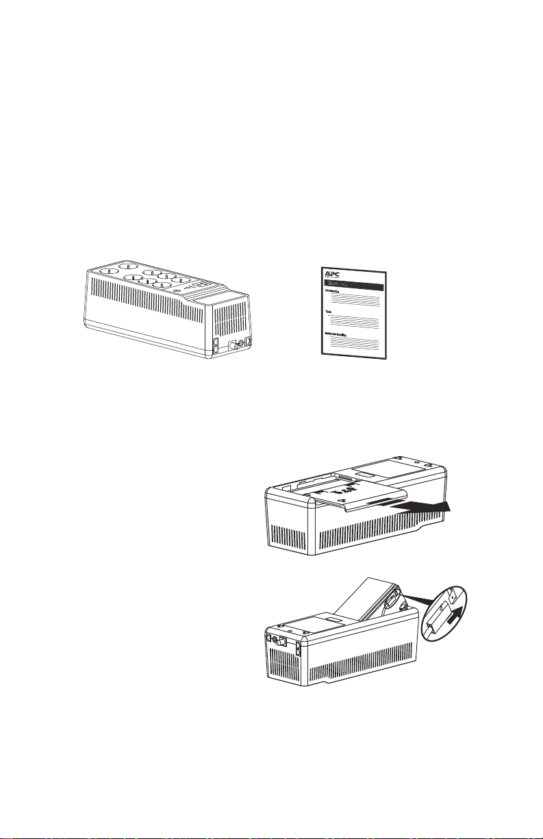
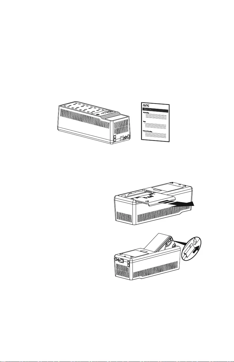
Комплектация
Back-UPS Краткое руководство пользователя
Подключение батареи
Снимите наклейку «Stop! Connect Battery» (Стоп! Подключите батарею) с
верхней крышки.
Переверните ИБП Back-UPS. Нажмите
на крышку батарейного отсека и
освободите фиксаторы. Сдвиньте
крышку батарейного отсека.
Надежно подключите кабель батареи к
клемме батареи.
Примечание: При подключении
кабеля батареи к клемме батареи
возможны небольшие искры.
Back-UPS BE650G2-RS/BE850G2-RS
3
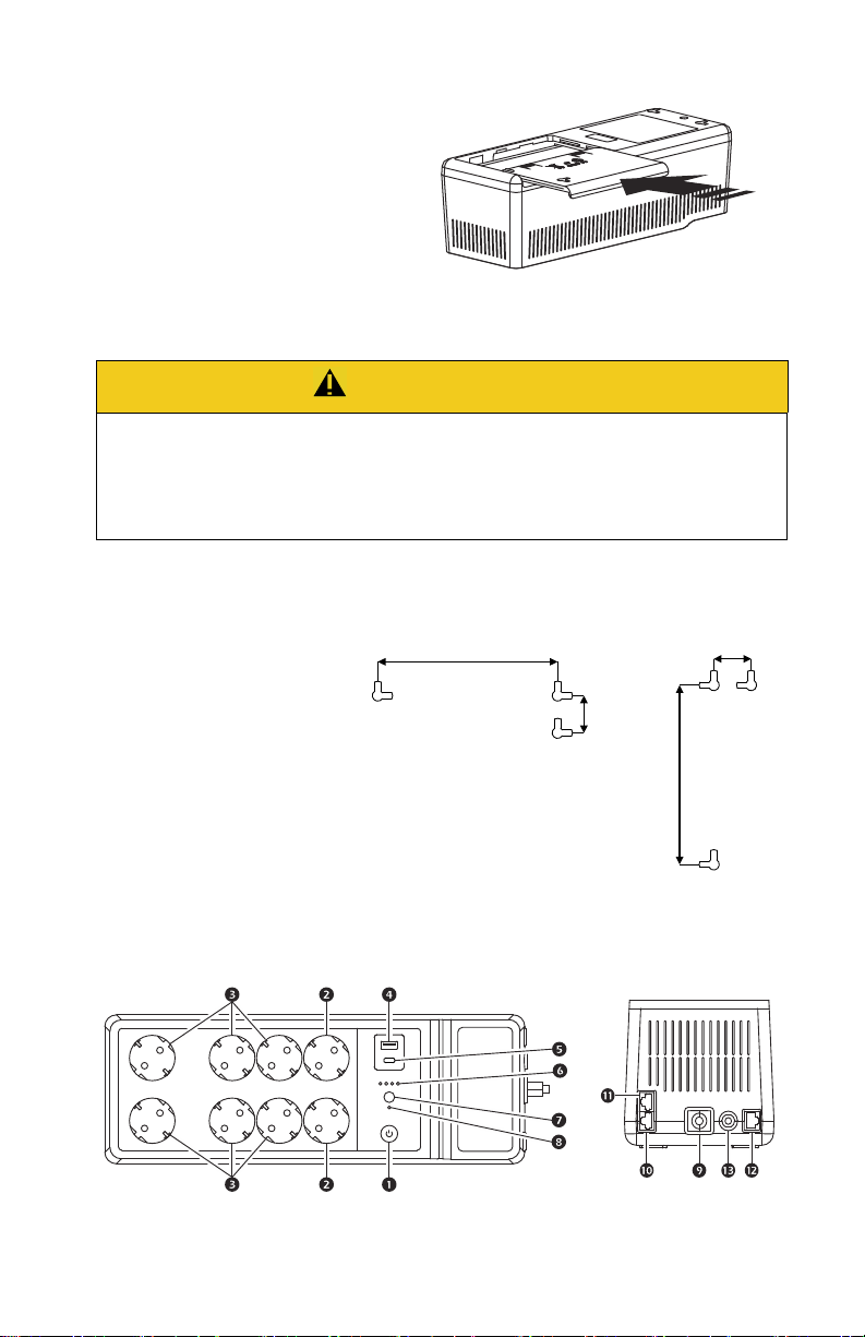
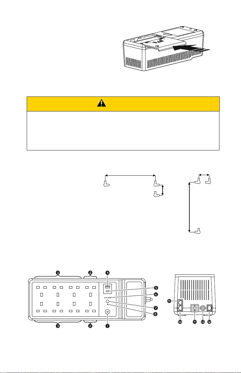
Установите на место крышку
батарейного отсека. Убедитесь, что
фиксаторы заблокировались.
Настенный монтаж
ОСТОРОЖНО
РИСК ПАДЕНИЯ ОБОРУДОВАНИЯ
Всегда применяйте безопасные методы подъема, соответствующие весу
оборудования.
Несоблюдение этих инструкций может привести к травме легкой или
средней тяжести и повреждению оборудования.
• Установите 3 винта
соответствующего размера
(не входят в комплект) в
соответствии с размерами,
показанными на
иллюстрациях
горизонтального/
вертикального монтажа.
• Винты должны выступать из
стены на 8 мм.
• Установите ИБП Back-UPS на
винты.
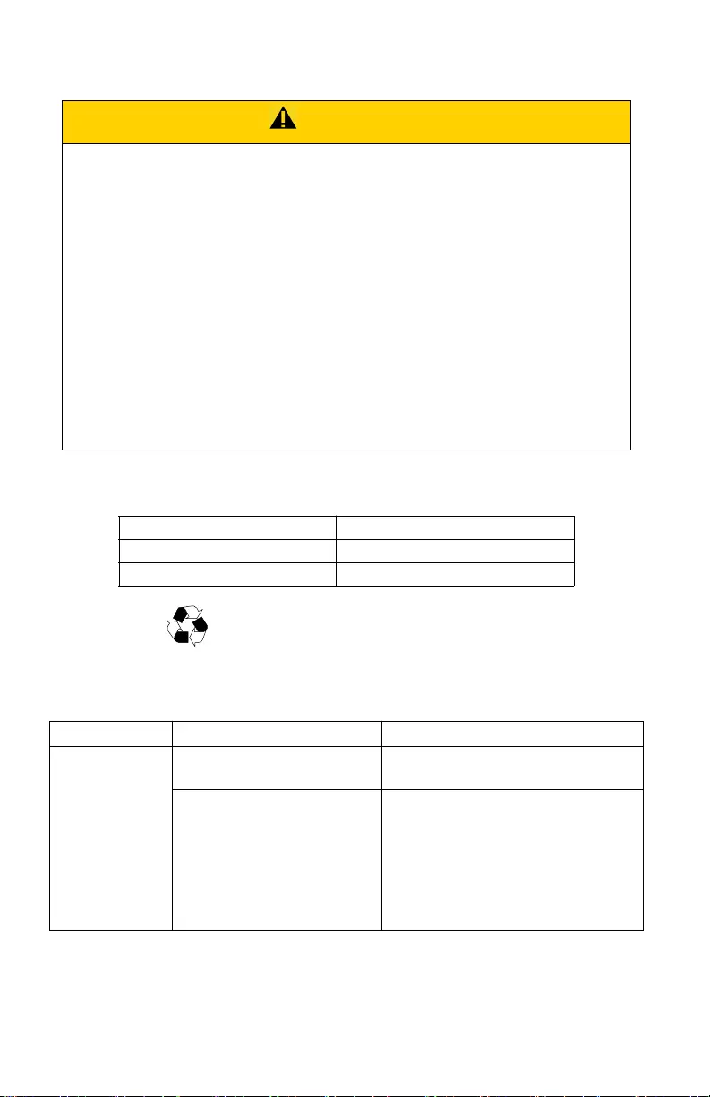
Функции панели
Гори зо нт аль ны й мо нт аж
Вертикальный
монтаж
Верхняя панель Боковая панель
Back-UPS BE650G2-RS/BE850G2-RS4

КНОПКА ВКЛ./
ВЫКЛ. ПИТАНИЯ и
индикатор
Розетки с
защитой от
перенапряжений
Розетки с
питанием от
резервной
батареи и розетки
с защитой от
перенапряжений
Зарядный USB-
порт Type A
Зарядный
USB-порт Type С
(только
BE850G2-RS)
Индикатор
состояния
батареи
НОПКА
К
ОТКЛЮЧЕНИЯ
ЗВУКА
НДИКАТОР
И
состояния
Используется для включения или выключения ИБП Back-UPS.
Индикатор горит зеленым, указывая на то, что к подключенному
оборудованию подается питание как от электросети, так и от батареи.
Прочие состояния индикатора питания описаны в разделе
«Индикаторы состояния» на стр. 8.
Розетки с защитой от перенапряжений обеспечивают защиту
подключенного оборудования от скачков напряжения, когда ИБП
Back-UPS включен и подключен к электросети. Подключайте к
этим розеткам периферийные устройства (такие как принтер,
сканер и т. д.), которым не нужно оставаться включенными во время
перебоев в подаче электроэнергии или при отключении питания.
Розетки с питанием от резервной батареи обеспечивают питание от
батареи в течение ограниченного периода времени при отключении
питания. Розетки с питанием от резервной батареи обеспечивают
защиту подключенного оборудования от скачков напряжения, когда
ИБП Back-UPS включен и подключен к электросети. Подключайте к
этим розеткам компьютер, монитор и другие периферийные
устройства, которые должны оставаться включенными во время
перебоев с питанием или при отключении питания.
Этот зарядный USB-порт обеспечивает максимум 2,4 A постоянного
тока. Порт будет заряжать подключенное оборудование, когда ИБП
Back-UPS включен.
Четыре индикатора состояния батареи показывают оставшееся
время работы. Когда батарея полностью заряжена, горят все четыре
индикатора. Более подробную информацию см. в разделе
«Индикаторы состояния» на стр. 8.
Нажмите КНОПКУ ОТКЛЮЧЕНИЯ ЗВУКА, чтобы включить или
отключить звук.
Горит, если включена функция отключения звука.
отключения звука
Входной шнур
питания
Порт DSL/
модемной сети/
факса
Подключите входной шнур питания к сетевой розетке (питание от
сети). Не подключайте шнур питания к сетевому фильтру или
удлинителю.
Подключите DSL или модем, телефон, факс или Ethernetоборудование 10/100 Base-T.
Примечание. Не подключайте порты защиты телефона ИБП
одновременно к телефонным и сетевым системным кабелям.
Настенная
розетка
Порт данных Подключите кабель RJ45/USB (не входит в комплект) для
Автоматический
выключатель
Подключите ИБП Back-UPS к настенной розетке линии данных.
подключения ИБП Back-UPS к компьютеру для установки
программного обеспечения. Подробную информацию см. в разделе
«Программное обеспечение PowerChute™ Personal Edition» на стр. 7.
Срабатывает, когда ИБП Back-UPS испытывает состояние
перегрузки.
Back-UPS BE650G2-RS/BE850G2-RS
5
Loading…
Displayed below is the user manual for BE850G2-UK by APC which is a product in the Uninterruptible Power Supplies (UPSs) category.
This manual has pages.
Important Safety Information
SAVE THESE INSTRUCTIONS — This manual contains important
instructions that should be followed during installation and maintenance of the
Back-UPS and batteries.
Read these instructions carefully and look at the equipment to become familiar
with the device before trying to install, operate, service or maintain it. The
following special messages may appear throughout this document or on the
equipment to warn of potential hazards or to call attention to information that
clarifies or simplifies a procedure.
The addition of this symbol to either a “Danger” or “Warning”
safety label indicates that an electrical hazard exists which will
result in personal injury if the instructions are not followed.
This is the safety alert symbol. It is used to alert you to potential
personal injury hazards. Obey all safety messages that follow this
symbol to avoid possible injury or death.
DANGER
DANGER indicates a hazardous situation which, if not avoided,
will result in death or serious injury.
WARNING
WARNING indicates a hazardous situation which, if not avoided,
could result in death or serious injury.
CAUTION
CAUTION indicates a hazardous situation which, if not avoided,
could result in minor or moderate injury.
NOTICE
NOTICE is used to address practices not related to physical
injury.
User Manual Back-UPS™
BE650G2-UK and BE850G2-UK

Back-UPS BE650G2-UK/BE850G2-UK2
Product Handling Guidelines
Safety and General Information
Inspect the package contents upon receipt. Notify the carrier and dealer if there
is any damage.
• This UPS is for indoor use only.
• Do not operate this UPS in direct sunlight, in contact with fluids, or
where there is excessive dust or high humidity.
• Do not operate the UPS near open windows or doors.
• Be sure the air vents on the UPS are not blocked. Allow adequate space
for proper ventilation.
Note: Allow a minimum of 20 cm clearance on both front and rear sides
of the UPS.
• Environmental factors impact battery life. Elevated ambient
temperatures, poor quality utility power, and frequent discharges will
shorten battery life. Follow the battery manufacturer recommendations.
• Connect the UPS power cable directly to a wall outlet. Do not use surge
protectors or extension cords.
Battery safety
• Servicing of batteries should be performed or supervised by personnel
knowledgeable about batteries and required precautions.
• APC by Schneider Electric uses Sealed Maintenance-Free Lead Acid
batteries. Under normal use and handling, there is no contact with the
internal components of the batteries. Over charging, over heating or
other misuse of batteries can result in leakage of battery electrolyte.
Released electrolyte is toxic and may be harmful to the skin and eyes.
• Use tool with insulated handles.
• Wear rubber gloves and boots.
• Determine if battery is either intentionally or inadvertently grounded.
Contact with any part of a grounded battery can result in electric shock
or burns by high short-circuit current. The risk of such hazards can be
reduced if grounds are removed during installation and maintenance by
a skilled person
.
<18 kg
<40 lb
18-32 kg
40-70 lb
32-55 kg
70-120 lb
>55 kg
>120 lb
Back-UPS BE650G2-UK/BE850G2-UK 3
• CAUTION: Before installing or replacing the batteries, remove
conductive jewelry such as chains, wrist watches, and rings.
High energy through conductive materials could cause severe burns.
• CAUTION: Do not dispose of batteries in a fire. The batteries may
explode.
• CAUTION: Do not open or mutilate batteries. Released material is
harmful to the skin and eyes and may be toxic.
Inventory
Connect the Battery
Back-UPS Quick start guide
Remove the “Stop! Connect Battery” label from the top cover.
Invert the Back-UPS. Press the battery
compartment cover and release the
tabs. Slide open the battery cover.
Connect the battery cable securely to
the battery terminal.
Note: It is normal for small sparks to
be seen when the battery cable is
connected to the battery terminal.
Back-UPS BE650G2-UK/BE850G2-UK4
Wall Mount Installation
Panel Features
Reinstall the battery compartment
cover. Be sure that the release tabs
lock into place.
CAUTION
RISK OF FALLING EQUIPMENT
Always practice safe lifting techniques adequate for the weight of the
equipment.
Failure to follow these instructions can result in minor or
moderate injury and equipment damage.
Horizontal mounting Vertical mounting
• Secure 3 screws of
appropriate size (not supplied)
as per dimensions shown in
the horizontal/vertical
mounting illustrations.
• Allow the screw to protrude
out 8mm from the wall.
• Mount the Back-UPS on to
the screws.
Top Panel Side Panel

Back-UPS BE650G2-UK/BE850G2-UK 5
POWER ON/OFF
button and
LED
Use to switch the Back-UPS on or off.
The LED illuminates green to indicate that power is supplied to the
connected equipment both on utility power and on battery. See “Status
Indicators” on page 8 for other status of the Power on/off LED.
Surge
protection
outlets
Surge protection outlets provide protection to connected equipment
from power surges or spikes, when the Back-UPS is turned on and
connected to utility power. Connect peripheral devices (such as printer,
scanner, etc.) that do not need to remain on during power outages or
brownout condition, to these outlets.
Battery
backup +
surge
protection
outlets
Battery backup outlets provide power from the battery for a limited
period of time during power outage, or brownout condition. Battery
backup outlets provide protection to connected equipment from power
surges or spikes, when the Back-UPS is turned on and connected to
utility power. Connect a computer, monitor and other peripheral
devices which need to remain on during power outages or brownout
condition, to these outlets.
Type A USB
charging port
This USB charging port provides a maximum of 2.4 A DC power. The
port will charge the connected equipment when the Back-UPS is
turned on.
Type C USB
charging port
(BE850G2-UK
only)
Battery status
LED
The four Battery status LEDs indicate the remaining runtime. When
battery is fully charged, all four LEDs illuminate. Refer “Status
Indicators” on page 8 for details.
MUTE button Press MUTE button to Enable or Disable the mute function.
Mute status
LED
Illuminates when the mute function is enabled.
Input power
cord
Connect the Input power cord to a wall outlet (utility power). Do not
connect the power cord to a surge protector or power strip.
DSL/modem
network/fax
port
Connect a DSL or Dial—up modem, Phone, Fax machine, or
10/100 Base-T Ethernet equipment.
Note: Do not connect the UPS telephone protection ports to both the
telephone and network system cables at the same time.
Wall outlet Connect the Back-UPS to a data line wall outlet.
Data port Connect a RJ45/USB cable (not supplied) to connect the Back-UPS to
a computer for installing the software. See “PowerChute™ Personal
Edition Software” on page 7 for details.
Circuit
breaker
Trips when the Back-UPS experiences an overload condition.

Back-UPS BE650G2-UK/BE850G2-UK6
Specifications
BE650G2-UK BE850G2-UK
Input Voltage 220 — 240 Vac
Frequency 47 to 63 Hz
Brownout Transfers 180 Vac Typical
Over-voltage Transfer 266 Vac Typical
Output UPS Capacity 650 VA, 400 W 850 VA, 520 W
Battery Backup outlets 2.96 A 3.87 A
Total Amperage 6 A
Voltage — On Battery 230 Vac ± 8%
Frequency — On Battery 50/60 Hz ± 1 Hz
Transfer Time 6 milliseconds Typical, 10 milliseconds
maximum
USB Port * Charging Rating 5 V; 2.40 A
Charger compatibility USB Battery Charging Specification 1.2
* Power output is dependent on the power drawn by the connected device.
Check with the device manufacturer to understand the maximum charging
current for a given USB specification.
Protection
and
Filtering
AC Surge Protection Full time, 310 Joules
EMI/RFI Filter Full time
Utility Power Input Resettable circuit breaker
Battery Type Sealed, maintenance-free, lead acid 12 V
Average Life 3 — 5 years, depending upon the number of
discharge cycles and environmental
temperature
Charging Time 16 hours.
Using the USB port while charging the battery
will increase the battery charging time
Physical Net Weight 8.8 lb (4 kg) 9.9 lb (4.5 kg)
Dimensions
L x W x H
14.4 in x 5.1 in x 4.7 in
36.5 cm x 13 cm x 12 cm
Operating Temperature 32 ºF to 104 ºF (0 ºC to 40 ºC)
Storage Temperature 5 ºF to 113 ºF (-15 ºC to 45 ºC)
Operating Relative Humidity 0 to 95% non-condensing humidity
IP Rating IP20

Back-UPS BE650G2-UK/BE850G2-UK 7
Turn On the Back-UPS
Press the POWER ON/OFF button located on the top of the Back-UPS. The
Power on/off LED will illuminate green and a single short beep will indicate
that the Back-UPS is on and providing protection to the connected equipment.
The Back-UPS battery charges to capacity during the first 24 hours while
connected to the utility power. The Back-UPS battery will charge while the
Back-UPS is turned on or off and as long as it is connected to utility power.
Do not expect the battery to run for its expected capacity during the initial
charge period. The UPS will have full runtime capability after the initial
24 hour charging period.
Turn Off the Back-UPS
Press the POWER ON/OFF button for at least 2 seconds to turn off the
Back-UPS. At the first beep, release the button and the UPS will turn off.
A 2 second delay has been added to mitigate unintentional contact with the
POWER ON/OFF button.
Mute
The audible alarms of the Back-UPS can be muted. Press the MUTE button to
enable or disable the mute function. The Mute status LED illuminates when
the mute function is enabled.
UPS Self Test
Press and hold the POWER ON/OFF button for 4 to 8 seconds to initiate the UPS
Self Test.
PowerChute™ Personal Edition Software
Overview
Use PowerChute Personal Edition software to configure the UPS settings,
protect your computer and other equipment during a utility power outage.
During a power outage, PowerChute will save any open files on your computer
and shut it down. When utility power is restored, it will restart the computer.
Note: PowerChute is only compatible with a Windows operating system. If
you are using Mac OSX, use the native shutdown feature to protect your
system. See the documentation provided with your computer.

Back-UPS BE650G2-UK/BE850G2-UK8
Installation
Note: To reduce electronic waste and protect the environment, USB cables are
no longer shipped in every box. Order the cable free of charge at
https://www.apc.com/usbcable.
Use the USB cable to connect the Data port on the UPS to the USB port on
your computer. Download PowerChute™ Personal Edition Software from
www.apc.com/pcpe. Select the appropriate operating system and follow
directions to download the software.
Status Indicators
Visual indicator
Audible
indicator Condition
Audible indicator
terminates
Power on/off LED
illuminates green
None Power On — The Back-UPS is
supplying utility power to the
connected equipment.
Not applicable.
Power on/off LED
flashes green twice
every 2 seconds
4 beeps
approx.
every 40
seconds.
On Battery — The Back-UPS is
supplying battery power to the
battery backup outlets.
Beeping stops when
utility power is
restored or the
Back-UPS is turned
off.
Power on/off LED
flashes green in quick
succession.
Rapid
beeping
(1 beep
every 0.5
second)
Low Battery notification The
Back-UPS is supplying battery
power to the battery backup
outlets and the battery is
nearing a total discharge state.
Power on/off LED
flashes green in quick
succession.
1 beep
every 4
seconds
Low Battery shutdown — The
battery has been completely
discharged while the
Back-UPS is on battery, the
Back-UPS will shutdown.
Beeping stops when
utility power is
restored or the
Back-UPS is turned
off.
None Sleep Mode — The Back-UPS
has shutdown and will return to
normal operation once utility
power is restored.
Not applicable.
Power on/off LED
flashes red and Battery
status LED flashes
green in quick
succession.
Constant
tone
Battery disconnected. Back-UPS is turned
off.
Power on/off LED
flashes green and red
alternately
Constant
tone
Replace battery — The battery
needs to be charged or replaced.
Back-UPS is turned
off.

Back-UPS BE650G2-UK/BE850G2-UK 9
Power on/off LED does
not illuminate
Constant
tone
Overload shutdown — An
overload condition in one or
more of the battery back up
outlets when the Back-UPS is
operating on battery power.
Back-UPS is turned
off.
Power on/off LED
flashes green and amber
alternately
None USB error detected — A short
circuit or an internal error has
been detected.
Not applicable.
Mute status LED
illuminates
None Mute function enabled. Not applicable.
Mute status LED does
not illuminate
None Mute function disabled. Not applicable.
When the Back-UPS is operating on battery power and the battery is getting
discharged
First Battery status
LED illuminates
None Remaining battery capacity is
0% to 24%.
Not applicable.
First two Battery status
LEDs illuminate
None Remaining battery capacity is
25% to 49%.
Not applicable.
First three Battery
status LEDs illuminate
None Remaining battery capacity is
50% to 74%.
Not applicable.
All 4 Battery status
LEDs illuminate
Non Remaining battery capacity is
75% to 100%.
Not applicable.
When the Back-UPS is on utility power and the battery is charging
First Battery status
LED flashes and the
other three Battery
status LED are not
illuminated
None Battery charge is 0% to 24%. Not applicable.
First Battery status
LED illuminates,
second Battery status
LED flashes, and other
two Battery status
LEDs are not
illuminated
None Battery charge is 25% to 49%. Not applicable.
First two Battery status
LEDs illuminate, third
Battery status LED
flashes and fourth
Battery status LED not
illuminated
None Battery charge is 50% to 74%. Not applicable.
Visual indicator
Audible
indicator Condition
Audible indicator
terminates

Back-UPS BE650G2-UK/BE850G2-UK10
Voltage Sensitivity Adjustment (Optional)
The Back-UPS will switch to battery power if the utility input voltage level or
distortions go out of range or if the utility power is experiencing voltage
fluctuations, to protect connected equipment. In situations where either the
Back-UPS or the connected equipment is too sensitive for the utility input
voltage level, it is necessary to adjust the transfer voltage.
1. Turn off the Back-UPS while connected to a wall outlet.
2. Press and hold the POWER ON/OFF button for 10 seconds. The
Power On/Off LED will alternate green and red to indicate that the
Back-UPS is in Program mode.
3. The Power On/Off LED will flash either green, amber, or red to indicate
the current sensitivity level. Refer to the table below for an explanation
of the transfer voltage sensitivity levels.
4. To exit Program mode wait five seconds and all LED indicators will turn
off. Program mode is no longer active.
First three Battery
status LEDs illuminate
and fourth Battery
status LED flashes
None Battery charge is 75% to 100%. Not applicable.
All four Battery status
LEDs illuminate
None Battery fully charged and
Back-UPS is on utility power.
Not applicable.
LED
Flashes
Sensitivity
Setting
Input Voltage
Range (Utility
Power Operation) Recommended Use
Green LOW 160 Vac to 278 Vac Use this setting when connected equipment is
less sensitive to fluctuations in voltage or
waveform distortions.
Red MEDIUM 180 Vac to 266 Vac Factory default setting. Use this setting under
normal conditions.
Amber HIGH 196 Vac to 256 Vac Use this setting when connected equipment is
sensitive to voltage and waveform
fluctuations.
Visual indicator
Audible
indicator Condition
Audible indicator
terminates
Back-UPS BE650G2-UK/BE850G2-UK 11
Replace Battery
Replacement batteries can be ordered through the APC by Schneider Electric
Web site, www.apc.com. .
Troubleshooting
CAUTION
RISK OF HYDROGEN SULPHIDE GAS AND EXCESSIVE SMOKE
• Replace the battery atleast every 5 years.
• Replace the battery immediately when the UPS indicates battery
replacement is necessary.
• Replace battery at the end of its service life.
• Replace batteries with the same number and type of batteries as
originally installed in the equipment.
• Replace the battery immediately when there is evidence of
electrolyte leakage. Power off the UPS, unplug it from the AC input,
and disconnect the batteries. Do not operate the UPS until the
batteries have been replaced.
Failure to follow these instructions could result in minor or
moderate injury and equipment damage.
Model Replacement battery part number
BE650G2-UK APCRBC110
BE850G2-UK RBC17
Deliver the used battery to a recycling facility.
Problem Possible Cause Corrective Action
The Back-UPS
will not turn on.
The Back-UPS has not been
turned on.
Press the POWER ON/OFF button.
The Back-UPS is not
connected to utility power, or
there is no utility power
available at the wall outlet, or
the utility power is
experiencing a brownout or
over voltage condition.
Be sure that the power cord is securely
connected to the wall outlet, and that
the utility power is available at the wall
outlet.Where applicable, be sure that
the wall outlet is switched on.

Back-UPS BE650G2-UK/BE850G2-UK12
The Back-UPS
will not turn on.
Back-UPS circuit breaker
tripped.
1. Disconnect all nonessential
equipment connected to the outlets.
2. Reset the circuit breaker by pushing
in the circuit breaker button fully
inwards until it latches.
3.If the circuit breaker resets, switch
On the Back-UPS and reconnect
one equipment at a time to the
Back-UPS.
4.If the circuit breaker trips again, it is
likely that one of the connected
devices is causing the overload.
The Back-UPS is
on, the Power
on/off LED
flashes red and
the unit emits a
constant tone.
The battery is disconnected. Connect the battery. Refer to “Connect
the Battery” on page 3 for details.
Connected
equipment loses
power.
A Back-UPS overload
condition has occurred.
• Disconnect all nonessential
equipment connected to the outlets.
Reconnect one equipment at a time to
the Back-UPS.
• Be sure that at least one Battery
status LED is illuminating. Charge
the battery for 16 hours to make sure
it is fully charged.
• If the overload condition still occurs,
replace the battery.
The Back-UPS battery is
completely discharged.
Connect the Back-UPS to utility power
and allow the battery to recharge for
16 hours.
PowerChute software has
performed a shutdown due to a
power outage.
This is a normal Back-UPS operation.
Connected equipment does not
accept the step—approximated
sine waveform from the
Back-UPS.
The output waveform is intended for
computers and peripheral devices. It is
not intended for use with motor driven
equipment.
The Back-UPS may require
service.
Contact Schneider Electric Technical
Support for more in-depth
troubleshooting.
Problem Possible Cause Corrective Action

Back-UPS BE650G2-UK/BE850G2-UK 13
The Power
On/Off LED is
green and
flashes twice
every 2 seconds.
The Back-UPS is operating on
battery power.
The Back-UPS is operating normally
on battery power. Save all open files,
and shutdown the computer. When
utility power is restored the battery will
recharge.
The Power
On/Off LED
flashes green in
rapid succession.
The Back-UPS battery has
approximately two minutes of
remaining runtime.
The Back-UPS battery is nearing total
discharge state. Save all open files, and
shutdown the computer. When utility
power is restored the battery will
recharge.
The Back-UPS
has an
inadequate
battery runtime.
The battery is not fully
charged.
Leave the Back-UPS connected to
utility power for 16 hours while the
battery charges to full capacity.
The battery is near the end of
useful life and should be
replaced.
As a battery ages, the runtime
capability decreases. See
APC by Schneider Electric Web site
www.apc.com, to order replacement
batteries.
USB charging is
slow.
Charging a device using the
Back-UPS USB charger is
slower than the device‘s
original USB charger.
The connected USB cable does not
support the charging speed for the
device. Use appropriate USB cable.
USB charging
stops and the
Power On/Off
LED illuminates
green and amber
alternatively.
The USB ports has detected a
short circuit or a fault.
Disconnect cable and device from the
USB port. USB charging will resume
when the Power On/Off LED turns
green. Contact Schneider Electric
Technical Support if the
Power On/Off LED continues to
illuminate green and amber
alternatively.
The Back-UPS is
off but the
Back-UPS beeps
twice every
30 seconds
(Quiet Alarm
mode) or beeps
once every 4
seconds (Full
Alarm mode).
The voltage is not low enough
to shutdown the Back-UPS but
not high enough to start the
Back-UPS and power the
outlets. There is however
enough voltage to charge the
Back-UPS.
Mute the alarm by pressing the MUTE
button. The UPS will return to normal
operation once the utility input voltage
has returned to normal range.
Problem Possible Cause Corrective Action

Back-UPS BE650G2-UK/BE850G2-UK14
Warranty
Register your product on-line. http://warranty.apc.com
The standard warranty is three (3) years from the date of purchase valid in
European Community. For all other regions, the standard warranty is
two (2) years from the date of purchase. Schneider Electric IT (SEIT) standard
procedure is to replace the original unit with a factory reconditioned unit.
Customers who must have the original unit back due to the assignment of asset
tags and set depreciation schedules must declare such a need at first contact
with an SEIT Technical Support representative. SEIT will ship the replacement
unit once the defective unit has been received by the repair department, or
cross ship upon the receipt of a valid credit card number. The customer pays
for shipping the unit to SEIT. SEIT pays ground freight transportation costs to
ship the replacement unit to the customer.
Service
If the unit requires service, do not return it to the dealer. Follow these steps:
1. Review the Troubleshooting section of the manual to eliminate common
problems.
2. If the problem persists, contact Schneider Electric IT (SEIT) Customer
Support through the Web site, www.apc.com.
a. Note the model number and serial number and the date of purchase.
The model and serial numbers are located on the rear panel of the unit
and are available through the LCD display on select models.
b. Call SEIT Customer Support and a technician will attempt to solve
the problem over the phone. If this is not possible, the technician will
issue a Returned Material Authorization Number (RMA#).
c. If the unit is under warranty, the repairs are free.
d. Service procedures and returns may vary internationally. Refer to the
APC by Schneider Electric Web site for country specific instructions.
3. Pack the unit in the original packaging whenever possible to avoid
damage in transit. Never use foam beads for packaging. Damage
sustained in transit is not covered under warranty.
4. Always DISCONNECT THE UPS BATTERIES before shipping.
The United States Department of Transportation (DOT), and the
International Air Transport Association (IATA) regulations require
that UPS batteries be disconnected before shipping. The internal
batteries may remain in the UPS.
5. Write the RMA# provided by Customer Support on the outside of the
package.
6. Return the unit by insured, pre-paid carrier to the address provided by
Customer Support

Back-UPS BE650G2-UK/BE850G2-UK 15

© 2019 APC by Schneider Electric. APC, the APC logo, Back-UPS, and
PowerChute are owned by Schneider Electric Industries S.A.S., or their affiliated
companies. All other trademarks are property of their respective owners.
EN 990-91287
07/2019
APC by Schneider Electric IT Customer Support
Worldwide
For country specific customer support, go to the APC by Schneider Electric
Web site, www.apc.com.
Table of Contents
- Safety and General Information
- Inventory
- Connect the Battery
- Install PowerChute ™ Personal Edition Software
- Connect the Equipment
- Operation
- Alarms and System Errors
- Troubleshooting
- Specifications
- Replacement Battery
- Warranty
- APC by Schneider Electric IT Customer Support Worldwide
- EMC Compliance
- Read User Manual Online (PDF format)
- Download This Manual (PDF format)
APC Back-UPS Pro BX850 User Manual

Safety and General Information
Inspect the package contents upon receipt. Notify the carrier and dealer if
there is any damage.
SAVE THESE INSTRUCTIONS – This section contains important instructions
that should be followed during installation and maintenance of the UPS and
batteries.
DANGER
HAZARD OF ELECTRIC SHOCK, EXPLOSION, OR ARC FLASH
- This UPS is intended for indoor use only.
- Do not operate this UPS in direct sunlight, in contact with fluids, or where there is excessive dust or humidity.
- Connect the UPS power cable directly to a wall outlet.
- Be sure the air vents on the UPS are not blocked. Allow adequate space for proper ventilation.
Failure to follow these instructions will result in death or serious injury.
Inventory

Connect the Battery
The UPS is shipped with the battery disconnected.
BX850/1000M/M-LM60
- Remove the battery door.
- Remove the battery. Connect the wire.
- Push the battery into the unit.
- Replace the battery door.
BX1350/1500M/M-LM60
- Remove the battery door.
- Remove the battery.
- Flip or turn the battery 180 degrees upward/downward to let green side of the label face up.

- Push the battery into the unit.
- Replace the battery door.

Install PowerChute ™ Personal Edition Software
Use PowerChute Personal Edition software to configure the UPS settings. During
a power outage, PowerChute will save any open files on your computer and shut
it down. When power is restored, it will restart the computer.
Note : PowerChute is only compatible with a Windows operating system. If
you are using Mac OSX, use the native shutdown feature to protect your system.
See the documentation provided with your computer.
Installation
Use the cable supplied with the Back-UPS to connect the data port on the Back-
UPS to the USB port on your computer. On the computer, go to
www.apc.com Search
for “PowerChute Personal Edition” then click on “View Details” to download the
latest version of PCPE software. Click the download link and select Software
product. Select the appropriate operating system. Follow directions to
download the software.
Connect the Equipment
Battery Backup and Surge Protected outlets
When the Back-UPS is receiving input power, the Battery Backup with Surge
Protection outlets will supply power to connected equipment. During a power
outage or other AC problems, the Battery Backup outlets receive power for a
limited time from the Back-UPS.
Connect equipment such as printers, fax machines, scanners, or other
peripherals that do not need battery backup power to the Surge Protection Only
outlets. These outlets provide full-time protection from surges even if the
Back-UPS is switched OFF


Operation
Power Saving Display
The display interface can be configured to be continuously illuminated, or to
save energy, it can be configured to darken after a period of inactivity.
- Full Time Mode : Press and hold DISPLAY for two seconds. The display will illuminate and the Back-UPS will beep to confirm the Full Time mode.
- Power Saving Mode : Press and hold DISPLAY for two seconds. The display will darken and the Back-UPS will beep to confirm the Power Saving mode. While in Power Saving Mode, the display will illuminate if a button is pressed, it then darkens after 60 seconds of no activity.
Unit sensitivity
Adjust the sensitivity of the Back-UPS to control when it will switch to
battery power; the higher the sensitivity, the more often the Back-UPS will
switch to battery power.
- Ensure the Back-UPS is connected to AC power, but is OFF.
- Press and hold the P OWER button for six seconds. The L OAD C APACITY bar will flash on and off, indicating that the Back-UPS is in programming mode.
- Press POWER again to rotate through the menu options. Stop at selected sensitivity. The Back-UPS will beep to confirm the selection.

Front Panel Buttons and Display Interface
Use the three buttons on the front panel of the Back-UPS and the display
interface to configure the Back-UPS.


Alarms and System Errors
Audible Indicators

Status Icons
System Errors
The Back-UPS will display these error messages. Except for errors F01 and F02,
contact SEIT Technical Support.

Function Button Quick Reference


Troubleshooting


Specifications

Replacement Battery
The battery typically lasts for 3 to 5 years, a shorter period if subjected to
frequent outages or elevated temperatures. Battery replacement parts for Back-
UPS BX850M/M-LM60 is RBC17, for BX1000M/M-LM60 is APCRBC158, for
BX1350M/M-LM60 is APCRBC123, and for BX1500M/M-LM60 is APCRBC124. Delaying the
replacement of parts may corrode the batteries in the cartridge. Recycle spent
battery cartridges.
Warranty
The standard warranty is three (3) years from the date of purchase. Schneider
Electric IT (SEIT) standard procedure is to replace the original unit with a
factory reconditioned unit. Customers who must have the original unit back due
to the assignment of asset tags and set depreciation schedules must declare
such a need at first contact with an SEIT Technical Support representative.
SEIT will ship the replacement unit once the defective unit has been received
by the repair department, or cross ship upon the receipt of a valid credit
card number. The customer pays for shipping the unit to SEIT. SEIT pays ground
freight transportation costs to ship the replacement unit to the customer.
APC by Schneider Electric IT Customer Support Worldwide
For country specific customer support, go to the APC by Schneider Electric Web
site, www.apc.com.
Select models are ENERGY STAR ® qualified.
For more information on your specific model go to
www.apc.com.
This UPS is certified to comply with California Battery Charger System
regulations. For more information go to
www.apc.com/company/us/en/sustainability/energy-efficiency/california-
battery-charger-regulations/
EMC Compliance
This equipment has been tested and found to comply with the limits for a Class
B digital device, pursuant to part 15 of the FCC Rules. These limits are
designed to provide reasonable protection against harmful interference in a
residential installation. This equipment generates, uses and can radiate radio
frequency energy and, if not installed and used in accordance with the
instructions, may cause harmful interference to radio communications. However,
there is no guarantee that interference will not occur in a particular
installation. If this equipment does cause harmful interference to radio or
television reception, which can be determined by turning the equipment off and
on, the user is encouraged to try to correct the interference by one or more
of the following measures:
- Reorient or relocate the receiving antenna.
- Increase the separation between the equipment and receiver.
- Connect the equipment into an outlet on a circuit different from that to which the receiver is connected.
- Consult the dealer or an experienced radio/TV technician for help.
© 2017 APC by Schneider Electric. APC, the APC logo, and Back-UPS are owned by
Schneider Electric Industries S.A.S. or their affiliated companies. All other
trademarks are property of their respective owners.
EN 990-5813A
07/2017
APC Back-UPS Pro BX850 User Manual – Optimized PDF
APC Back-UPS Pro BX850 User Manual – Original PDF
Read User Manual Online (PDF format)
Read User Manual Online (PDF format) >>
Download This Manual (PDF format)
Download this manual >>