
RAD Data comm
ASMi-52 Инструкция по эксплуатации
Популярность:
18175 просмотры
Подсчет страниц:
186 страницы
Тип файла:
Размер файла:
3.91 Mb
-
Page 1: RAD Data comm ASMi-52
Installation and Operation Manual AS M i — 5 2 2 /4-Wire SHDSL Modem Version 2.5[…]
-
Page 2: RAD Data comm ASMi-52
[…]
-
Page 3: RAD Data comm ASMi-52
ASMi-52 Version 2.5 2/4-Wire SHDSL Modem Installation and Operation Manual Notice T h i s m a n u a l c o n t a i n s i n f o r m a t i o n t h a t i s p r o p r i e t a r y t o R A D D a t a C o m m u n i c a t i o n s L t d . ( » R A D » ) . N o part of this publication may be reproduced in any form whatsoever without prior written appr[…]
-
Page 4: RAD Data comm ASMi-52
Limited Warranty RAD warrants to DISTRIBUTOR that the hardware in the A SMi- 52 to be de livered hereunder s hall be free of defects in material and workmanshi p under no rmal use and service for a period of twelve (12) months following the date of shipment to DISTRIBUTOR. If, during the warranty period, any component part of the equipment becomes […]
-
Page 5: RAD Data comm ASMi-52
General Safety Instructions The following in structions ser ve as a general guid e for the safe installation and op eration of telecommunications products. Addition al i nstructions, if appl icable, are included ins ide the manual. Safety Symbols This symbol may appear on the equipment or in the text. It indicates potential safety hazards regarding[…]
-
Page 6: RAD Data comm ASMi-52
Handling Energized Products General Safety Practices Do not touch or tamper with the power supply when the power cord is connecte d. Line voltages may be present inside certain product s even wh en the power switch (if installed) is in the OFF position or a fuse is blown. For DC-powered products, alth ough the voltages levels are usua lly not hazar[…]
-
Page 7: RAD Data comm ASMi-52
Connection of Data and Telecommunications Cables Data and telecommunicatio n interfaces are classified accor ding to their safety status. The following table list s the status of several standard in terfaces. If the st atus of a given port differs from the standard one, a no tice will be given i n the manual. Ports Safety Status V.11, V.28, V.35, V[…]
-
Page 8: RAD Data comm ASMi-52
To reduce the risk of fire, use only No. 26 AWG or larger telecommunication line cords. Pour réduire les risques s’incendie, utiliser seulement des conducteurs de télécommunications 26 AWG ou de section supérieure. Some ports are suitable for connection to intra-buildin g or non-exposed wiring or cabling only. In such cases, a notice will be […]
-
Page 9: RAD Data comm ASMi-52
Canadian Emission Requirements This Class A digital apparatus meets all the requirements of the Canadian Interference-Causing Equipment Regulation. Cet appareil numérique de la classe A respecte to utes les exigences du Règlement sur le matériel brouilleur du Canada. Warning per EN 55022 (CISPR- 22) This is a class A product. In a domestic envir[…]
-
Page 10: RAD Data comm ASMi-52
Declaration of Conformity Manufacturer’s Name: RAD Data Communications Ltd. Manufacturer’s Address: 24 Raoul Wallenberg St. Tel Aviv 69719 Israel declares that the product: Product Name: ASMi-52 Conforms to the following standard(s ) or other normative document(s): EMC: EN 55022: 1994 Limits and methods of measurement of radio disturbance[…]
-
Page 11: RAD Data comm ASMi-52
ASMi-52 Ver. 2.5 Configuring ASMi-52 1 Quick Start Guide Installation of ASMi-52 should be carried out only by an experienced technician. If you are familiar with ASMi-52, use this gu ide to prepare the units for operation. 1. Installing ASMi-52 Connecting the Interfaces 1. Connect the line to the RJ-45 re ar panel connector dedicated SHDSL. 2. Con[…]
-
Page 12: RAD Data comm ASMi-52
Quick Start Guide Installation and Operation Manual 2 Configuring ASMi-52 ASMi-52 Ver. 2.5 Configuring the Master Cloc k To configure the master clock: • From the System Configuration menu (Main Menu > Configurat ion > System Configuration > Ma ster Clock), configure the central ASMi-52 clock to external or internal and remote AS Mi-[…]
-
Page 13: RAD Data comm ASMi-52
Installation and Operation Manual Quick Start Guide ASMi-52 Ver. 2.5 Configuring ASMi-52 3 To configure E1 parameters: • From the E1 Port Configuration menu (Main Menu > Configuration > Port Configuration > E1 Port Configuration), configure the following E1 parameters: Framing mode Timeslot assignment • You can configure ti[…]
-
Page 14: RAD Data comm ASMi-52
Quick Start Guide Installation and Operation Manual 4 Configuring ASMi-52 ASMi-52 Ver. 2.5[…]
-
Page 15: RAD Data comm ASMi-52
ASMi-52 Installation and Operation Manual i Contents Chapter 1. Introduction 1.1 Overview ……………………………………………………………………………………………………… 1-1 Versio ns ……………………………………………………………………………………………………….. ……..[…]
-
Page 16: RAD Data comm ASMi-52
Table of Contents ii ASMi-52 Installation and Operation Manual Setting the G.704 Interfac e Type …………………………………………………………………………….. 4-21 4.3 Configuring the Physical P orts ………………………………………………………………………… 4-22 Configuring the SH DSL Interface[…]
-
Page 17: RAD Data comm ASMi-52
ASMi-52 Ver. 2.5 Overview 1-1 Chapter 1 Introduction 1.1 Overview ASMi-52 is an SHDSL mo dem that operates in full- duplex over 2/4-wire lines an d offers a cost-effective solution for delivering digital data to customer pre mises over existing copper cables. AS Mi-52 handl es multiple data rates in the range of 64–4608 kbps. The unit is availabl[…]
-
Page 18: RAD Data comm ASMi-52
Chapter 1 Introduction Installation and Operation Manual 1-2 Overview ASMi-52 Ver. 2.5 Unit Enclosure ASMi-52 is available in a plastic, metal, or rail-mount enclosure. Applications Figure 1-1 illustrates a typ ical ASMi-52 application, in which standalone modems operate opposite each other. Figure 1-2 shows ASMi- 52 units operating op posite a cen[…]
-
Page 19: RAD Data comm ASMi-52
Installation and Operation Manual Chapter 1 Introduction ASMi-52 Ver. 2.5 Overview 1-3 Figure 1-2. ASMi-52 Mo dems Operating O pposite a Centrall y Located LRS-24 Rack Figure 1-3. ASMi-5 2 Modems Op erating opposite ASMi-52CD Cards[…]
-
Page 20: RAD Data comm ASMi-52
Chapter 1 Introduction Installation and Operation Manual 1-4 Overview ASMi-52 Ver. 2.5 Features Functionality ASMi-52 can be configured to operate in a CO (central office) or CPE (custo mer premises equipment) mode. Line Interface ASMi-52 extends the ran ge of data transmission ov er 2/4-wire lines up to 7.0 km (4.3 miles), by employing SHDSL TC-P […]
-
Page 21: RAD Data comm ASMi-52
Installation and Operation Manual Chapter 1 Introduction ASMi-52 Ver. 2.5 Overview 1-5 DTE Interface ASMi-52 supports the following DTE interfaces: • X.21 • V.35 • RS-530 • E1, as per G.704 • T1 • Ethernet/Fast Ethernet bridge with VLAN support (combined with man agement LAN port) • IR-IP (IP router). When ASMi-52 is ordere d only wit[…]
-
Page 22: RAD Data comm ASMi-52
Chapter 1 Introduction Installation and Operation Manual 1-6 Overview ASMi-52 Ver. 2.5 Table 1-2. ASMi-52 D ata Rates DTE Interface and Clock Mode Line Interface Local ASMi-52 Remote ASMi-52 2-wire 4-wire Serial DTE interface, internal clock Serial DTE interface n × 64 kbps (n = 1, 2, … 32, 36) n × 128 kbps ( n = 1, 2, …32, 36) Serial DTE int[…]
-
Page 23: RAD Data comm ASMi-52
Installation and Operation Manual Chapter 1 Introduction ASMi-52 Ver. 2.5 Overview 1-7 Multiplexer Applications • The multiplexer unit cannot be configured as a device with L AN only port. It must have a DTE or IR port. • The hardware of a single unit-based pr oduct with a LAN port ma nager is different from that of a mu ltiplexer-based product[…]
-
Page 24: RAD Data comm ASMi-52
Chapter 1 Introduction Installation and Operation Manual 1-8 Overview ASMi-52 Ver. 2.5 Table 1-4. Possible Mu ltiplexer Applications (Cont.) CO/CPE E1 Serial DTE LAN E1+Serial DTE E1+LAN Serial DTE+LAN E1 ↔ E1 E1 ↔ Serial DTE E1 ↔ LAN E1 ↔ E1+Serial DTE E1 ↔ E1 E1 ↔ Serial DTE E1+LAN ↔ E1 E1 ↔ E1 E1 ↔ Serial DTE E1 ↔ E1+LAN E1 ?[…]
-
Page 25: RAD Data comm ASMi-52
Installation and Operation Manual Chapter 1 Introduction ASMi-52 Ver. 2.5 Overview 1-9 • Receive, recovered from the received line signal (CPE mode). Management ASMi-52 supports the following management options: • ASCII terminal or Easy Config hand-hel d device via V.24/RS-232 terminal port • Telnet via a dedicated 10/100BaseT port • SNMP n[…]
-
Page 26: RAD Data comm ASMi-52
Chapter 1 Introduction Installation and Operation Manual 1-10 Functional Description ASMi-52 Ver. 2.5 Statistics Collection ASMi-52 supports SHDSL and E1/T1 statistics collection. Alarm Reporting ASMi-52 alarms are relayed via a dedi cated 6-pin terminal block connector. SHDSL Repeaters Up to eight SHDSL repeaters can be installed in l ine to incre[…]
-
Page 27: RAD Data comm ASMi-52
Installation and Operation Manual Chapter 1 Introduction ASMi-52 Ver. 2.5 Functional Description 1-11 Modem Glue Logi c Data & Clock LED s an d T erm i na l I nt er fa c e Con trol S ignal s CPU 10/ 100B as eT Ma nage ment Por t CPU Data Bus DTE Interfa ce SHDSL Li ne I nt erf ac e Power Supp ly Internal Oscill ator Figure 1-5. ASMi-52/ 4W with[…]
-
Page 28: RAD Data comm ASMi-52
Chapter 1 Introduction Installation and Operation Manual 1-12 Technical Specifications ASMi-52 Ver. 2.5 Internal oscillator – Serves as a source of internal clock for the ASMi-52 unit. Modem glue logic module – Processes the data from/to the SH DSL interface module. SHDSL line interface – Translates the received and transmitted data from the […]
-
Page 29: RAD Data comm ASMi-52
Installation and Operation Manual Chapter 1 Introduction ASMi-52 Ver. 2.5 Technical Specifications 1-13 • T1: 100 Ω , balanced Connector Type • X.21: 15-pin, D-type, female • V.35 – 34-pin, female • RS-530 – 25-pin, D-type, female • G.70 3/G.704 E1 – RJ-45, balanced or unbalanced ( via adapter cable) • T1 – RJ-45 • IR-IP ( I[…]
-
Page 30: RAD Data comm ASMi-52
Chapter 1 Introduction Installation and Operation Manual 1-14 Technical Specifications ASMi-52 Ver. 2.5 Alarm Relay Operation Normally Open and Normally Closed, using different pins Connector Terminal block, 6-pin Indicators PWR (green) Power TEST (red) Test SYNC A/B (green/red) Synchronization of DSL line DATA (yellow) Data Transfer (except E1 and[…]
-
Page 31: RAD Data comm ASMi-52
Installation and Operation Manual Chapter 1 Introduction ASMi-52 Ver. 2.5 Technical Specifications 1-15 Environment Temperature Standalone: 0 ° to 50 ° C (32 ° to 122 ° F) Rail-mount: − 20 ° to 70 ° C ( − 4 ° to 158 ° F) Humidity Up to 90%, non–condensing Shock (Rail-Mount) IEC 60068-2-27 shock 1 5g, 11 ms duration, 18 shocks Vibratio[…]
-
Page 32: RAD Data comm ASMi-52
Chapter 1 Introduction Installation and Operation Manual 1-16 Technical Specifications ASMi-52 Ver. 2.5[…]
-
Page 33: RAD Data comm ASMi-52
ASMi-52 Ver. 2.5 Site Requi rements and Prerequisites 2-1 Chapter 2 Installation and Setup 2.1 Introduction This chapter describes installation and setup procedures for the standalone ASMi-52 modem. After installing the unit: • Refer to Chapter 3 for the operating instructions. • Refer to Chapter 4 for the detailed system conf igura tion proced[…]
-
Page 34: RAD Data comm ASMi-52
Chapter 2 Installation and Setup Installation and Operation Manual 2-2 Connecting the Interface Cables ASMi-52 Ver. 2.5 Allow at least 90 cm (36 in) of fronta l clearance for operation and maintenance accessibility. Allow at least 10 cm (4 in) cl earance at the rear of the unit for signal lines and interface cables. The ambient operating temperatur[…]
-
Page 35: RAD Data comm ASMi-52
Installation and Operation Manual Chapter 2 Installation and Setup ASMi-52 Ver. 2.5 Connecting the Power Cables 2-3 Connecting the Line The ASMi-52 line interface terminates in an 8-pin RJ-45 connector. To connect the line connector: • Connect the line cable to the RJ -45 connector designated SHDSL. Connecting the DTE Interface The ASMi-52 DT[…]
-
Page 36: RAD Data comm ASMi-52
Chapter 2 Installation and Setup Installation and Operation Manual 2-4 Connecting the Power Cables ASMi-52 Ver. 2.5 Before connecting this unit to a powe r source and connecting or disconnecting any other cable, the protective earth terminals of this unit must be conn ected to the protective ground conductor of the mains (AC or DC) power cord. If y[…]
-
Page 37: RAD Data comm ASMi-52
ASMi-52 Ver. 2.5 Controls and Indicators 3-1 Chapter 3 Operation This chapter provides the following information for the ASMi-52 modem: • ASMi-52 front-panel indicators • Operating procedures (turn-on, fron t-panel indications, performance monitoring and turn-off) • ASMi-52 default settings. Installation procedures giv en in Chapter 2 mu st b[…]
-
Page 38: RAD Data comm ASMi-52
Chapter 3 Operation Installation and Operation Manual 3-2 Controls and Indicators ASMi-52 Ver. 2.5 ASMi-5 2 Figure 3-1. ASMi-52 Fr ont Panel, E1 Interface (2 Wire ) Figure 3-2. ASMi-52 Fr ont Panel, E1 Interface (4 Wire ) Figure 3-3. ASMi-52 Fr ont Panel, T1 Interface (4 Wir e) ASMi-5 2 Figure 3-4. ASMi-52 Front Panel, DTE Serial Interface (4 Wire)[…]
-
Page 39: RAD Data comm ASMi-52
Installation and Operation Manual Chapter 3 Operation ASMi-52 Ver. 2.5 Controls and Indicators 3-3 Table 3-1. ASMi-52 Front Panel LEDs Name Function PWR (green) On – Power is ON TST (red) On – A loopback test is active in a local or remote unit SYNC A (red/green) On (red) – Link A is not synchronized On (green) – Link A is synchronized Blin[…]
-
Page 40: RAD Data comm ASMi-52
Chapter 3 Operation Installation and Operation Manual 3-4 Default Settings ASMi-52 Ver. 2.5 3.3 Default Settings ASMi-52 is managed by an ASCII ter minal or a PC running a terminal emulation program via a menu-driv en embedded so ftware. Table 3-4 lists the default settings of the ASMi-52 conf iguration parameters. Table 3-4. Default Settings Param[…]
-
Page 41: RAD Data comm ASMi-52
Installation and Operation Manual Chapter 3 Operation ASMi-52 Ver. 2.5 Default Settings 3-5 Parameter Default Value Control Port Control port rate 9600 bps Data 8 Parity None Interface DCE CTS =RTS DSR ON Port control mode Terminal User name – Password 1234 Pop alarm OFF Security timeout 10 min Call Out Mode None Number of retries 1 Wait for conn[…]
-
Page 42: RAD Data comm ASMi-52
Chapter 3 Operation Installation and Operation Manual 3-6 Configuration Alternatives ASMi-52 Ver. 2.5 Parameter Default Value Serial DTE Interface Rate Single: 2-wire – 192 kbps 4-wire – 384 kbps Multiplexer: 1. E1+Serial DTE, N/A , 0 kbps 2. LAN+Serial DTE: 2-wire – 192 kbps 4-wire – 384 kbps LLB from DTE Disable RLB from DTE Disable E1/E1[…]
-
Page 43: RAD Data comm ASMi-52
Installation and Operation Manual Chapter 3 Operation ASMi-52 Ver. 2.5 Configur ation Alternatives 3-7 • Remote management via out-of- band 10/1 00BaseT port or dedi cated timeslot. Remote management is p erformed us ing Telnet, or ConfiguR AD (RAD’s Web-based application), or RADvie w (RAD’s SNMP -based management system). Managing ASMi-52 v[…]
-
Page 44: RAD Data comm ASMi-52
Chapter 3 Operation Installation and Operation Manual 3-8 Configuration Alternatives ASMi-52 Ver. 2.5 3. Configure the terminal to the defa ult communication para meters: 9.6 kbps, one start bit, eight data bits, no parity, one stop bit, VT100 e mulation. 4. Select the full duplex mo de. 5. Turn the terminal echo off. 6. Disa ble any type of flow c[…]
-
Page 45: RAD Data comm ASMi-52
Installation and Operation Manual Chapter 3 Operation ASMi-52 Ver. 2.5 Configur ation Alternatives 3-9 Managing ASMi-52 via Ethernet Port ASMi-52 is equipped with an Etherne t/Fast Ethernet port (10/100BaseT) which enables communication with ASMi-52 management subs ystem using the IP protocol (see Figure 3-9 ). The Ethernet management port is confi[…]
-
Page 46: RAD Data comm ASMi-52
Chapter 3 Operation Installation and Operation Manual 3-10 Configuration Alternatives ASMi-52 Ver. 2.5 session over the dedicated timeslot ha s priority ove r management via the 10/100BaseT port. 1. Connect the E1/T1 line to the ASMi-52 E1 or T1 port. 2. Start a terminal management sess ion and do the following: Assig n an IP address and an IP […]
-
Page 47: RAD Data comm ASMi-52
Installation and Operation Manual Chapter 3 Operation ASMi-52 Ver. 2.5 Configur ation Alternatives 3-11 • Trace – opens an additional pane for s ystem messages, progress indicators (ping, software and co nfiguration fi le downloads) and alarms. It is recommended to keep the trace pane open all the time. • Refresh All – refreshes all screen […]
-
Page 48: RAD Data comm ASMi-52
Chapter 3 Operation Installation and Operation Manual 3-12 Configuration Alternatives ASMi-52 Ver. 2.5 Figure 3-10. Inventory and Configurati on Menus[…]
-
Page 49: RAD Data comm ASMi-52
Installation and Operation Manual Chapter 3 Operation ASMi-52 Ver. 2.5 Configur ation Alternatives 3-13 Figure 3-11. Monitoring, Diagno stics and File Utilities Menus[…]
-
Page 50: RAD Data comm ASMi-52
Chapter 3 Operation Installation and Operation Manual 3-14 Turning Off ASMi-52 ASMi-52 Ver. 2.5 Logging Out To end the current session: • In the Main m enu, click Logout or type & in a terminal management screen. • • ASMi-52 allo ws at least four management se ssions to be active at a time. If the Web-based management sessi ons were n[…]
-
Page 51: RAD Data comm ASMi-52
ASMi-52 Ver. 2.5 Configuring ASMi-52 for Management 4-1 Chapter 4 Configuration 4.1 Configuring ASMi-52 for Management The configuration of ASMi-52 is performed via a menu-dr iven embedded software, using a standard ASCII terminal or a PC running a terminal emulat ion application connected to the rear panel CONTROL port. Altern atively, ASMi-52 can[…]
-
Page 52: RAD Data comm ASMi-52
Chapter 4 Configuration Installation and Operation Manual 4-2 Configuring ASMi-52 for Management ASMi-52 Ver. 2.5 Entering Device Information The Device Information menu allows you to assign a name to ASMi-52, define its location, and contact person. These entries may include up to 20 characters. To enter device information: 1. Display the Sys […]
-
Page 53: RAD Data comm ASMi-52
Installation and Operation Manual Chapter 4 Configuration ASMi-52 Ver. 2.5 Configuring ASMi-52 for Management 4-3 Configuring the Host Parameters ASMi-52 can be managed by a netw ork management station, w hich is located on the LAN connected to the 10/100BaseT po rt. In order to establish a pro per connection, it is necessary to configure the follo[…]
-
Page 54: RAD Data comm ASMi-52
Chapter 4 Configuration Installation and Operation Manual 4-4 Configuring ASMi-52 for Management ASMi-52 Ver. 2.5 3. Type a nu mber corresponding to a subnet mask of t he already defined network management station, and ente r a new value. 4. Repeat step 2 an d step 3 to defi ne addit ional management stations. 5. Press <Esc> to return to the […]
-
Page 55: RAD Data comm ASMi-52
Installation and Operation Manual Chapter 4 Configuration ASMi-52 Ver. 2.5 Configuring ASMi-52 for Management 4-5 ASMi-52 Management Access 1. TELNET allowed (access allowed) 2. WEB allowed (access allowed) > ESC-prev. menu; !-main menu; &-exit; @-scroll Figure 4-6. Mana gement Access Menu Configuring Dedicated Timeslots ASMi-52 units with a[…]
-
Page 56: RAD Data comm ASMi-52
Chapter 4 Configuration Installation and Operation Manual 4-6 Configuring ASMi-52 for Management ASMi-52 Ver. 2.5 ASMi-52 Rem Agent Table SOURCE IP DESTINATION IP PORT > ESC-prev. menu; !-main menu; &-exit; @-scroll; ?-help Figure 4-8. R em Agent Table Configuring VLAN Encapsulation ASMi-52 is occasionally connected to a VLAN network when ma[…]
-
Page 57: RAD Data comm ASMi-52
Installation and Operation Manual Chapter 4 Configuration ASMi-52 Ver. 2.5 Configuring ASMi-52 for Management 4-7 Configuring the LAN Port ASMi-52 includes a 10/100BaseT port that can be used as a user or management port. The LAN port operates in a self-learning bridge or transparent mode, w ith or without autonegotiation. • If the LAN port serve[…]
-
Page 58: RAD Data comm ASMi-52
Chapter 4 Configuration Installation and Operation Manual 4-8 Configuring ASMi-52 for Management ASMi-52 Ver. 2.5 Filling out the Bridging Table When the 10/100BaseT port operates in the bridge mode, yo u can assign MAC addresses to the local or remote LAN. To fill out the bridge table: 1. Select Bridging Table from the Local LAN Config uration[…]
-
Page 59: RAD Data comm ASMi-52
Installation and Operation Manual Chapter 4 Configuration ASMi-52 Ver. 2.5 Configuring ASMi-52 for Management 4-9 ASMi-52 Bridge Table Type (Static) 1. MAC Address … (00000000000) 2. Port … () > ESC-prev. menu; !-main menu; &-exit; ?-help Figure 4-12. Bridge Table, Editing Mode Configuring Aging Timeout The aging time is the timeout peri[…]
-
Page 60: RAD Data comm ASMi-52
Chapter 4 Configuration Installation and Operation Manual 4-10 Configuring ASMi-52 for Management ASMi-52 Ver. 2.5 ASMi-52 QoS Mapping (Classification 802.1p) 1. User Priority 0 > (Traffic Class 0) 2. User Priority 1 > (Traffic Class 0) 3. User Priority 2 > (Traffic Class 0) 4. User Priority 3 > (Traffic Class 0) 5. User Priority 4 >[…]
-
Page 61: RAD Data comm ASMi-52
Installation and Operation Manual Chapter 4 Configuration ASMi-52 Ver. 2.5 Configuring ASMi-52 for Management 4-11 ASMi-52 Data Rate (2304 Kbps) 1. 64 Kbps 12. 768 Kbps 23. 1472 Kbps 2. 128 Kbps 13. 832 Kbps 24. 1536 Kbps 3. 192 Kbps 14. 896 Kbps 25. 1600 Kbps 4. 256 Kbps 15. 960 Kbps 26. 1664 Kbps 5. 320 Kbps 16. 1024 Kbps 27. 1728 Kbps 6. 384 Kbp[…]
-
Page 62: RAD Data comm ASMi-52
Chapter 4 Configuration Installation and Operation Manual 4-12 Configuring ASMi-52 System Parameters ASMi-52 Ver. 2.5 2. If the autonegotiation is e nabled, choose Max AutoNeg Capabil ity from the Local LAN Configuration menu. The Set Capability menu appears. 3. Select the required LAN operation mo de by choosing one o f the following: 10BaseT […]
-
Page 63: RAD Data comm ASMi-52
Installation and Operation Manual Chapter 4 Configuration ASMi-52 Ver. 2.5 Configuring AS Mi-52 System Parameters 4-13 ASMi-52 Configuration > 1. System configuration > 2. LAN configuration > 3. SHDSL configuration 4. E1 configuration 5. T1 configuration 6. DTE configuration > ESC-prev. menu; !-main menu; &-exit; @-scroll Figure 4-1[…]
-
Page 64: RAD Data comm ASMi-52
Chapter 4 Configuration Installation and Operation Manual 4-14 Configuring ASMi-52 System Parameters ASMi-52 Ver. 2.5 Configuring the Master Cloc k ASMi-52 modems support receive, exte rnal and internal clock modes. When configured to the internal or extern al clock, ASMi-52 modem operates as a n STU-C unit. When configured to the receive clock, AS[…]
-
Page 65: RAD Data comm ASMi-52
Installation and Operation Manual Chapter 4 Configuration ASMi-52 Ver. 2.5 Configuring AS Mi-52 System Parameters 4-15 ASMi-52 Local/Remote Card Mode 1. E1 2. DTE 3. E1 + LAN 4. E1 + V35 5. V35 + LAN > ESC-prev. menu; !-main menu; &-exit; @-scroll Figure 4-19. Local/Remote Card Mode Menu Configuring Remote Ca rd Mode The remote card mode con[…]
-
Page 66: RAD Data comm ASMi-52
Chapter 4 Configuration Installation and Operation Manual 4-16 Configuring ASMi-52 System Parameters ASMi-52 Ver. 2.5 Configuring Control Port Pa rameters The embedded ASMi-52 software enables you to c onfigure the Control port parameters. To access the Control port menu: • From the System Configuration menu, select Control Port (Main menu &g[…]
-
Page 67: RAD Data comm ASMi-52
Installation and Operation Manual Chapter 4 Configuration ASMi-52 Ver. 2.5 Configuring AS Mi-52 System Parameters 4-17 Selecting the Contro l Por t Interfa ce To select the control port interface: 1. From the Control Port menu, select Interface (Main menu > Configuration > System Configuration > Control Port > Interface) to choose t[…]
-
Page 68: RAD Data comm ASMi-52
Chapter 4 Configuration Installation and Operation Manual 4-18 Configuring ASMi-52 System Parameters ASMi-52 Ver. 2.5 ASMi-52 Port Control 1. Port Control Mode > (Terminal) 2. Terminal > 3. Dial out > 4. Save > ESC-prev. menu; !-main menu; &-exit; @-scroll Figure 4-22. Port Control Menu Configuring the Port Control Mode The Control […]
-
Page 69: RAD Data comm ASMi-52
Installation and Operation Manual Chapter 4 Configuration ASMi-52 Ver. 2.5 Configuring AS Mi-52 System Parameters 4-19 ASMi-52 Terminal 1. Change access > 2. POP ALARM (No) 3. Security timeout (10 min) 4. Save > ESC-prev. menu; !-main menu; &-exit; @-scroll Figure 4-24. Terminal Menu To change the user name and password: 1. From t he […]
-
Page 70: RAD Data comm ASMi-52
Chapter 4 Configuration Installation and Operation Manual 4-20 Configuring ASMi-52 System Parameters ASMi-52 Ver. 2.5 To configure the security timeout: 1. From t he Terminal menu, select Security Timeout (Main menu > Configuration > System Configuratio n > Control Port > Port Control > Terminal > Security Timeout) to configur[…]
-
Page 71: RAD Data comm ASMi-52
Installation and Operation Manual Chapter 4 Configuration ASMi-52 Ver. 2.5 Configuring AS Mi-52 System Parameters 4-21 3 to specify the time (in sec) ASMi-52 waits for an answer after each dial ing attempt. If the called station does not answer within the specified time, ASMi-52 disconnects. If addition al call attempts are allowed, ASMi-52 red[…]
-
Page 72: RAD Data comm ASMi-52
Chapter 4 Configuration Installation and Operation Manual 4-22 Configuring the Physical Ports ASMi-52 Ver. 2.5 4.3 Configuring the Physical Ports Configuring the SHDSL Interface The ASMi-52 configuration soft ware allows you to c hange the modem’s transmission mode (A nnex A or Annex B). Examples given below illustrate the lo cal device configura[…]
-
Page 73: RAD Data comm ASMi-52
Installation and Operation Manual Chapter 4 Configuration ASMi-52 Ver. 2.5 Configuring the Physical Ports 4-23 ASMi-52 SHDSL remote port configuration Transmission mode (Annex_AB) Asym PSD (Asym/Sym Enable) Line prob (Adaptive rate) 1. Power backoff (Enable) 2. Snext margin (Disable Snext margin) 3. Current margin (Disable current margin) 4. Loop a[…]
-
Page 74: RAD Data comm ASMi-52
Chapter 4 Configuration Installation and Operation Manual 4-24 Configuring the Physical Ports ASMi-52 Ver. 2.5 2. Select the Snext margin by typing th e number corresponding to the required value. The SHDSL Remote Port menu appears. 3. Select Save to save the changes. ASMi-52 Snext margin (Disable Snext margin) 1. -10 12. 1 2. -9 13. 2 3. -8 14. 3 […]
-
Page 75: RAD Data comm ASMi-52
Installation and Operation Manual Chapter 4 Configuration ASMi-52 Ver. 2.5 Configuring the Physical Ports 4-25 Configuring the Power Spectral Density By configuring the power spectral dens ity, you define the amoun t of power applied to the spectrum of frequencies that carry the informat ion signal in order to achieve a satisfactory level of signal[…]
-
Page 76: RAD Data comm ASMi-52
Chapter 4 Configuration Installation and Operation Manual 4-26 Configuring the Physical Ports ASMi-52 Ver. 2.5 Configuration > SHDSL Local Port/SHDSL Remote Port/SHDSL Repeater > Loop Attenuation Threshold). The loop attenuation threshold can be configured from the SHDSL remote or local port, or from the SHDSL repeater. 2. Enter the required […]
-
Page 77: RAD Data comm ASMi-52
Installation and Operation Manual Chapter 4 Configuration ASMi-52 Ver. 2.5 Configuring the Physical Ports 4-27 Configuring the DTE Interface Data Rate ASMi-52 supports multiple data rate s between the range of 64 kbps and 4608 kbps, depending on the clock mode and line/DTE interface of the local and remote units (see Table 1-2 an d Table 1-3 ). […]
-
Page 78: RAD Data comm ASMi-52
Chapter 4 Configuration Installation and Operation Manual 4-28 Configuring the Physical Ports ASMi-52 Ver. 2.5 Configuring the E1 Interface The following are commonly used acronyms: • CO – Central Office, where the clock sour ce is set to internal or external • CPE – customer premise equipment. When ASMi-52 includes a G.7 04 E1 port, you ca[…]
-
Page 79: RAD Data comm ASMi-52
Installation and Operation Manual Chapter 4 Configuration ASMi-52 Ver. 2.5 Configuring the Physical Ports 4-29 ASMi-52 E1 Local Port 1. Framed mode (G732N) 2. Sync mode (CCITT(complies with G732)) 3. CRC-4 (NO) 4. Idle code (ff) 5. Time slots assign 6. Unit Identical Set (Yes) 7. Number TS for remote E1 8. Save > ESC-prev. menu; !-main menu; &am[…]
-
Page 80: RAD Data comm ASMi-52
Chapter 4 Configuration Installation and Operation Manual 4-30 Configuring the Physical Ports ASMi-52 Ver. 2.5 ASMi-52 Framed mode (Unframed) 1. Unframed 2. G732N 3. G732S transparent > ESC-prev. menu; !-main menu; &-exit; @-scroll Figure 4-34. Framed Mode Menu Enabling CRC-4 Code Generation You have to enable the CRC-4 code generation if yo[…]
-
Page 81: RAD Data comm ASMi-52
Installation and Operation Manual Chapter 4 Configuration ASMi-52 Ver. 2.5 Configuring the Physical Ports 4-31 ASMi-52 Sync mode (CCITT (complies with G732)) 1. FAST (after 1 sec) 2. 62411 (after 10 sec) 3. CCITT (complies with G732) > ESC-prev. menu; !-main menu; &-exit; @-scroll Figure 4-35. Sync Mode Menu Defining Idle Code You can define[…]
-
Page 82: RAD Data comm ASMi-52
Chapter 4 Configuration Installation and Operation Manual 4-32 Configuring the Physical Ports ASMi-52 Ver. 2.5 • • You can configure timeslot 0 to be looped or transp arent: Looped – timeslot 0 is sent back to the E1 interface, when operating opposite remote units with a serial data interface. Transparent – timeslot 0 is tran smitte[…]
-
Page 83: RAD Data comm ASMi-52
Installation and Operation Manual Chapter 4 Configuration ASMi-52 Ver. 2.5 Configuring the Physical Ports 4-33 ASMi-52 has a multiplexer mo dem with two interfa ces. The maximum timeslots that can be used are as follows: • If E1 + LAN, then the maximum TSs (t imeslots) = (2048 kbps – LAN rate) / 64 kbps. • If E1 + Serial DTE, then t he maximu[…]
-
Page 84: RAD Data comm ASMi-52
Chapter 4 Configuration Installation and Operation Manual 4-34 Configuring the Physical Ports ASMi-52 Ver. 2.5 • The Unit Identical Set is permanently set to Yes, the parameters are copied to the remote unit. If the Frame Mode is not G732S: • The Unit Identical setting can be set to Yes or No when the local modem is configured as CO and both mo[…]
-
Page 85: RAD Data comm ASMi-52
Installation and Operation Manual Chapter 4 Configuration ASMi-52 Ver. 2.5 Configuring the Physical Ports 4-35 • Transmit signal mask (DSU mode) – le ng th of a cable in feet between the ASMi-52 T1 port connector and the n etwork access point: 0 fe et – 0 to 133 feet 13 3 feet – 133 to 266 feet 26 6 feet — 266 to 399 feet 39[…]
-
Page 86: RAD Data comm ASMi-52
Chapter 4 Configuration Installation and Operation Manual 4-36 Additional Tasks ASMi-52 Ver. 2.5 4.4 Additional Tasks Displaying the ASMi-52 Status The ASMi-52 software allows you to disp lay the modem system and physical port information. The status information is a vailable via the Monitoring menu. To access the Monitoring menu: • From the […]
-
Page 87: RAD Data comm ASMi-52
Installation and Operation Manual Chapter 4 Configuration ASMi-52 Ver. 2.5 A dditional Tasks 4-37 ASMi-52 System Status Local Remote Device Type (ASMi52_SA_M (PLASTIC)-STU_C-2W) ASMi52_SA Clock Source (INT) RCV Software Version (2.01E24) (2.01E24) Hardware Version (0.00) (0.00) FPGA Version (0.13) (0.13) Hardware Status (NO HARDWARE FAILURE) (NO HW[…]
-
Page 88: RAD Data comm ASMi-52
Chapter 4 Configuration Installation and Operation Manual 4-38 Additional Tasks ASMi-52 Ver. 2.5 • The physical port alarms are described in Chapter 5 . 2. Type N to display the next page. Accessing the Remote ASMi-52 Accessing the remote ASMi-52 is performe d using a virtual connection with your terminal physically connected to the local unit. ?[…]
-
Page 89: RAD Data comm ASMi-52
Installation and Operation Manual Chapter 4 Configuration ASMi-52 Ver. 2.5 A dditional Tasks 4-39 Figure 4-42. Password Reques t Screen (ConfiguRAD Session) To enter the user name and password: 1. Type in your user name a nd press <Tab> . • You can leave the user name field empty (default), the default password is 12 34. 2. Type in your[…]
-
Page 90: RAD Data comm ASMi-52
Chapter 4 Configuration Installation and Operation Manual 4-40 Additional Tasks ASMi-52 Ver. 2.5 Figure 4-44. Main Menu (ConfiguRAD Session) Displaying the ASMi-52 Inventory The ASMi-52 inventory displays in formation on the functional blocks of the local or remote modem. ASMi-52 consists of the following components: • SHDSL unit • DTE unit •[…]
-
Page 91: RAD Data comm ASMi-52
Installation and Operation Manual Chapter 4 Configuration ASMi-52 Ver. 2.5 A dditional Tasks 4-41 ASMi-52 Inventory 1 Index 1001 Description RAD-local ASMi-52_M SHDSL modem Vendor type Contained in 0 Class 3 Rel pos 0 Name SHDSL modem HW ver 0.00 SW ver 1.00E54 ->> > ESC-prev. menu; !-main menu; &-exit; @-scroll; ?-help Figure 4-45. In[…]
-
Page 92: RAD Data comm ASMi-52
Chapter 4 Configuration Installation and Operation Manual 4-42 Additional Tasks ASMi-52 Ver. 2.5 ASMi-52 TFTP TFTP status (No operation) TFTP error (No error) 1. TFTP IP server (172.17.160.103) 2. TFTP file name (201e24.img) 3. TFTP retry timeout (sec) [0-300] (15) 4. TFTP total timeout (sec) [0-4000] (1200) 5. Save 6. Transfer command > ESC — p[…]
-
Page 93: RAD Data comm ASMi-52
Installation and Operation Manual Chapter 4 Configuration ASMi-52 Ver. 2.5 A dditional Tasks 4-43 For exit press Q(uit) If you press <Q> , ASMi-52 aborts the download process and displays Download failure. Press Esc to continue. message in addition to the previous display. • During the software installation, the TST in dicator blinks. 2. Se[…]
-
Page 94: RAD Data comm ASMi-52
Chapter 4 Configuration Installation and Operation Manual 4-44 Additional Tasks ASMi-52 Ver. 2.5 5. From the TFTP menu, pe rform the foll owing steps: Select TFTP IP Server and enter the IP address of the TFTP server Select TFTP File N ame and enter the name of the software file (for example, 201e24.img ). Select TFTP Retry Timeo ut and[…]
-
Page 95: RAD Data comm ASMi-52
Installation and Operation Manual Chapter 4 Configuration ASMi-52 Ver. 2.5 A dditional Tasks 4-45 ASMi-52 SW files Local Remote Software active version: (2.01E24) (2.02000) Software active partition: (0) (0) Code size: (813110) (813161) Date: (28-7-4) (2-8-4) Software backup version: (2.01E24) (2.01E11) Software backup partition: (1) (1) Code size:[…]
-
Page 96: RAD Data comm ASMi-52
Chapter 4 Configuration Installation and Operation Manual 4-46 Additional Tasks ASMi-52 Ver. 2.5 Resetting to Default Settings You can reset the local or remote ASMi-52 to it s default settings. Resetting to the factory default does not affect the master clock setting. In addition, you can reset the local ASMi-52 without affecting it s ma nagement […]
-
Page 97: RAD Data comm ASMi-52
Installation and Operation Manual Chapter 4 Configuration ASMi-52 Ver. 2.5 A dditional Tasks 4-47 2. From th e Reset menu, select Local Reset to reset the local modem or Remo te Reset to reset the remote device. The Local/Remote Reset menu appears (see Figure 4-51 ). 3. From the Local/Remote Reset menu, select Local/Remote Device Reset to perform t[…]
-
Page 98: RAD Data comm ASMi-52
Chapter 4 Configuration Installation and Operation Manual 4-48 Additional Tasks ASMi-52 Ver. 2.5 ASMi-52 Repeater Reset 1. Repeater SHDSL line reset . . . 2. Repeater number > (1) > ESC-prev. menu; !-main menu; &-exit; @-scroll Figure 4-52. Repeater Reset Menu Exiting the Control Session You can exit the terminal control session any time […]
-
Page 99: RAD Data comm ASMi-52
ASMi-52 Ver. 2.5 Overview 5-1 Chapter 5 Configuring a Typical Application 5.1 Overview This chapter provides detailed instr uctions for setting up t wo ASMi-52 modems i n a typical application. ASMi-52 configuration is performed via a men u-driven embedded software using a standard ASCII terminal or a PC r unning a terminal emulatio n application c[…]
-
Page 100: RAD Data comm ASMi-52
Chapter 5 Configuring a Typical Ap plication Installation and Operation Manual 5-2 Configuring the ASMi-52 units ASMi-52 Ver. 2.5 5.2 Configuring the ASMi-52 units Two ASMi-52 units must be configured for this app lication. Both units have t he same configuration parameters, except for the host IP address and the master clock mode. To prepare a[…]
-
Page 101: RAD Data comm ASMi-52
Installation and Operation Manual Chapter 5 Configuring a Typical Application ASMi-52 Ver. 2.5 Configur ing the ASMi-52 units 5-3 Set the CO ASMi- 52 unit clock to Internal. Set the CPE ASMi-52 unit clock to Receive. 3. Select Save to save the changes. To set the device host IP address: 1. Displa y the host IP menu (Mai n menu > Conf[…]
-
Page 102: RAD Data comm ASMi-52
Chapter 5 Configuring a Typical Ap plication Installation and Operation Manual 5-4 Configuring the ASMi-52 units ASMi-52 Ver. 2.5 2. From t he Framed Mode menu, select Unframed to choose the unframed operation. The E1 Local Port menu appears. 3. Save the changes. After performing these config uration proc edures, the ASMi-52 units are ready to be c[…]
-
Page 103: RAD Data comm ASMi-52
Installation and Operation Manual Chapter 5 Configuring a Typical Application ASMi-52 Ver. 2.5 Configur ing the ASMi-52 units 5-5 ASMi-52 DTE local port configuration > 1. LLB from DTE : (Enable/Disable) 2. RLB from DTE : (Enable/Disable) 3. Data rate : (1984 kbps) 4. Save > ESC-prev. menu; !-main menu; &-exit; @-scroll Figure 5-6. DTE Lo[…]
-
Page 104: RAD Data comm ASMi-52
Chapter 5 Configuring a Typical Ap plication Installation and Operation Manual 5-6 Configuring the ASMi-52 units ASMi-52 Ver. 2.5[…]
-
Page 105: RAD Data comm ASMi-52
ASMi-52 Ver. 2.5 Monitoring Performance 6-1 Chapter 6 Troubleshooting and Diagnostics This chapter describes the ASMi- 52 di agnostic funct ions, which include: • Status indications, alarms, power-up self-test • Statistics collection • Bit Error Rate Test (BERT) • Diagnostic tests (loopback s and LEDs test). 6.1 Monitoring Performance Displ[…]
-
Page 106: RAD Data comm ASMi-52
Chapter 6 Troubleshooting and Diagnostics Installation and Operation Manual 6-2 Monitoring Performance ASMi-52 Ver. 2.5 2. From th e Physical Port Statistics menu, select SHDSL Port Performances to display the unit’s SDHSL statistics. The SDHSL Port Performances menu appears (see Figure 6- 2 ). ASMi-52 SHDSL Port Performances 1. SHDSL current per[…]
-
Page 107: RAD Data comm ASMi-52
Installation and Operation Manual Chapter 6 Troubleshooting and Diagnostics ASMi-52 Ver. 2.5 Monitoring Performance 6-3 ASMi-52 SHDSL current day performances Local A Local B Remote A Remote B Port number (1) (1) (1) (1) 24 hour ES (1) (1) (1) (1) 24 hour UAS (1401) (1401) (1401) (1401) 24 hour SES (0) (0) (0) (0) 24 hour LOWS (0) (0) (0) (0) 24 ho[…]
-
Page 108: RAD Data comm ASMi-52
Chapter 6 Troubleshooting and Diagnostics Installation and Operation Manual 6-4 Monitoring Performance ASMi-52 Ver. 2.5 ASMi-52 SHDSL all intervals local/remote performances … Line A Line B INT CRC LOSWS ES SES UAS CRC LOSWS ES SES UAS ESC-prev. menu; !-main menu; &-exit; ?-help; @-scroll Figure 6-5. S HDSL All Interv als Local/Remote Perform[…]
-
Page 109: RAD Data comm ASMi-52
Installation and Operation Manual Chapter 6 Troubleshooting and Diagnostics ASMi-52 Ver. 2.5 Monitoring Performance 6-5 • For details on enabling th e CRC-4 function, refer to Chapter 4 . • For the details on configur ing T1 fr aming, refer to Configuring T1 I nterface in Chapter 4. Displaying the Current E1/T1 Statistics To display the cur[…]
-
Page 110: RAD Data comm ASMi-52
Chapter 6 Troubleshooting and Diagnostics Installation and Operation Manual 6-6 Monitoring Performance ASMi-52 Ver. 2.5 ASMi-52 E1/T1 current day performance Local Remote Port number (1) No statistics collection ESC-prev. menu; !-main menu; &-exit; @-scroll Figure 6-9. E1/T1 Current Day Performances Screen Table 6-2. E1/T1 Statistic s Parameter[…]
-
Page 111: RAD Data comm ASMi-52
Installation and Operation Manual Chapter 6 Troubleshooting and Diagnostics ASMi-52 Ver. 2.5 Monitoring Performance 6-7 Table 6-2. . E1 Statistics Parameters (C ont.) Display Description Range Current DM Number of degraded minutes in which the B ER exceeded 1 × 10 -6 . This value is updated every minute for 15-m inute interval or every 24 hours fo[…]
-
Page 112: RAD Data comm ASMi-52
Chapter 6 Troubleshooting and Diagnostics Installation and Operation Manual 6-8 Handling Alarms ASMi-52 Ver. 2.5 Clearing the E1/T1 Statistics To clear E1/T1 statistics: • From the E1 Port Performances menu (see Figure 6-2 ), select E1 /T1 Clear Local Performances or E1 /T1 Clear Remote Performances (Main menu > Monitoring > Physical Po[…]
-
Page 113: RAD Data comm ASMi-52
Installation and Operation Manual Chapter 6 Troubleshooting and Diagnostics ASMi-52 Ver. 2.5 Handling Alarms 6-9 Displaying All Alarms ASMi-52 allows you to displa y all alarms, irrespective of their origin (system or port). To display all alarms: 1. From the Main menu, select Monitoring . The Monitoring menu appears (see Figure 6-11 ). 2. From[…]
-
Page 114: RAD Data comm ASMi-52
Chapter 6 Troubleshooting and Diagnostics Installation and Operation Manual 6-10 Handling Alarms ASMi-52 Ver. 2.5 ASMi-52 System Monitoring 1. System status 2. System log file 3. System clear log file … > ESC-prev.menu; !-main menu; &-exit; @-scroll Figure 6-13. System Moni toring Menu Working with the System Log File ASMi-52 maintains sys[…]
-
Page 115: RAD Data comm ASMi-52
Installation and Operation Manual Chapter 6 Troubleshooting and Diagnostics ASMi-52 Ver. 2.5 Handling Alarms 6-11 ASMi-52 Physical port status Port Number (1) 1. Port status 2. Line mask (NO_MASK) 3. Port log file 4. Port clear log file > ESC-prev. menu; !-main menu; &-exit; @-scroll Figure 6-14. Physical Port Status Menu Masking Port Alarms[…]
-
Page 116: RAD Data comm ASMi-52
Chapter 6 Troubleshooting and Diagnostics Installation and Operation Manual 6-12 Handling Alarms ASMi-52 Ver. 2.5 Table 6-3. ASMi-52 Alarms and Warn ings (Cont.) Number Terminal Message Port Description Severity 12 SNR MARGIN OVER LINE B SHDSL Line B signal-to-noise margin has exceeded the alarm threshold (4-wire units only) Minor 13 LOSW FAILURE O[…]
-
Page 117: RAD Data comm ASMi-52
Installation and Operation Manual Chapter 6 Troubleshooting and Diagnostics ASMi-52 Ver. 2.5 Handling Alarms 6-13 Table 6-3. ASMi-52 Alarms and Warn ings (Cont.) Number Terminal Message Port Description Severity 32 E1 EXCESIVE ERR RATIO T1 EXCESIVE ERR RATIO DTE The bit error rate of the link exceed s 10 -3 Major 33 E1 AIS OCCURED T1 AIS OCCURED DT[…]
-
Page 118: RAD Data comm ASMi-52
Chapter 6 Troubleshooting and Diagnostics Installation and Operation Manual 6-14 Handling Alarms ASMi-52 Ver. 2.5 Table 6-3. ASMi-52 Alarms and Warn ings (Cont.) Number Terminal Message Port Description Severity 45 LOOP ATTN. OVER CUSTOMER SIDE SHDSL Loop attenuation at the customer side of the repeater has exceeded the alarm threshold. Major (all)[…]
-
Page 119: RAD Data comm ASMi-52
Installation and Operation Manual Chapter 6 Troubleshooting and Diagnostics ASMi-52 Ver. 2.5 Troubleshooting 6-15 Table 6-4. ASMi-52 Events Terminal Message Description CRC EVENT LINE A CRC errors are detected on line A CRC EVENT LINE B CRC errors are detected on line B SW DOWNLOAD FAIL Software download failed BUFFER OVERFLOW More than 100 entries[…]
-
Page 120: RAD Data comm ASMi-52
Chapter 6 Troubleshooting and Diagnostics Installation and Operation Manual 6-16 Testing ASMi-52 ASMi-52 Ver. 2.5 ASMI 52 Port log file Source Name Severity Status Time 1. Local MNGMNT IS DOWN MAJOR ON 0:00:00 2. Local E1 SYNC LOSS LINE A MAJOR ON 0:00:00 3. Local E1 SIGNAL LOSS MAJOR ON 0:00:00 4. Local SYNC LOSS LINE A MAJOR ON 0:00:00 5. Local E[…]
-
Page 121: RAD Data comm ASMi-52
Installation and Operation Manual Chapter 6 Troubleshooting and Diagnostics ASMi-52 Ver. 2.5 Testing ASMi-52 6-17 Bit Error Rate Test (BERT) It is possible to generate BERT+RLB or BERT (from both CO and CPE) in multiplexer and E1 and DTE Serial single units. The BERT, RLB + BERT can be set o nly if there is a connection to the FE unit. BERT Pattern[…]
-
Page 122: RAD Data comm ASMi-52
Chapter 6 Troubleshooting and Diagnostics Installation and Operation Manual 6-18 Testing ASMi-52 ASMi-52 Ver. 2.5 ASMi-52 Bert 1. Bert (ON/OFF) 2. Bert + RLB (ON/OFF) 3. Bert pattern > 4. Save Bert parameters > ESC-prev. menu ; !–main menu ; &–exit terminal Figure 6-16. BERT Menu 3. From the Ber t menu, select Bert Pattern (see Figure[…]
-
Page 123: RAD Data comm ASMi-52
Installation and Operation Manual Chapter 6 Troubleshooting and Diagnostics ASMi-52 Ver. 2.5 Testing ASMi-52 6-19 ASMi-52 Bert Results Local Remote Run time (seconds) 2000 Sync loss state sync loss Sync run time (seconds) 2000 Sync loss counter 2000 Total bits 3000 Error bits 50 BER 5.5E-4 > ESC-prev. menu; !–main menu ; &–exit terminal […]
-
Page 124: RAD Data comm ASMi-52
Chapter 6 Troubleshooting and Diagnostics Installation and Operation Manual 6-20 Testing ASMi-52 ASMi-52 Ver. 2.5 Figure 6-20. Loopback with Multiplexer Units Running the Local Loopback The local loopback (LLB) checks the pe rformance of the local ASMi-52 modem, the local DTE and the connection between them (see Figure 6-21 ). The LLB can be perfor[…]
-
Page 125: RAD Data comm ASMi-52
Installation and Operation Manual Chapter 6 Troubleshooting and Diagnostics ASMi-52 Ver. 2.5 Testing ASMi-52 6-21 To run the local loopback: 1. From the Main menu, select Diagnost ics . The Diagnostics menu is displayed (see Figure 6-22 ). 2. From th e Diagnostics menu, select: Local Test to run the LLB on the local ASMi-52 Remote Test […]
-
Page 126: RAD Data comm ASMi-52
Chapter 6 Troubleshooting and Diagnostics Installation and Operation Manual 6-22 Testing ASMi-52 ASMi-52 Ver. 2.5 Running the Remote Loopback The remote loopback (RLB) checks the performanc e of both the local and remote ASMi-52 modems, an d the li nes connecting them (see Figure 6-24 ). ASMi-52 allows you to set the loopbac k timeout causing the R[…]
-
Page 127: RAD Data comm ASMi-52
Installation and Operation Manual Chapter 6 Troubleshooting and Diagnostics ASMi-52 Ver. 2.5 Testing ASMi-52 6-23 To activate the remote loopback at the SHDSL repeater : 1. From t he Diagnostics menu, select Repeater Test (Main menu > Diagnostics > Repeater Test). The Repeater Test menu appears (see Figure 6-26 ). 2. From the Repeater Tes[…]
-
Page 128: RAD Data comm ASMi-52
Chapter 6 Troubleshooting and Diagnostics Installation and Operation Manual 6-24 Frequently Asked Questions ASMi-52 Ver. 2.5 To deactivate multiple loopbacks: • From the Local or Remote Test menu, select Clear All . The TST indicator turns off. Running the LEDs Test The user can perform the front-panel LED test to verify that the local unit i[…]
-
Page 129: RAD Data comm ASMi-52
Installation and Operation Manual Chapter 6 Troubleshooting and Diagnostics ASMi-52 Ver. 2.5 Technical Support 6-25 6.7 Technical Support Technical support for this product can be obtained from the local distrib utor from whom it was purchased. For further information, please contact th e RAD distributor nearest you or one of RAD’s offices wor[…]
-
Page 130: RAD Data comm ASMi-52
Chapter 6 Troubleshooting and Diagnostics Installation and Operation Manual 6-26 Technical Support ASMi-52 Ver. 2.5[…]
-
Page 131: RAD Data comm ASMi-52
ASMi-52 Ver. 2.5 DTE Interface Connectors A-1 Appendix A Interface Connector Specifications A.1 DTE Interface Connectors V.35, X.21 and RS-530 Interface Connectors The V.35 interface of the ASMi-52 mo dem terminates in a 34 -pin female connector. The X.21 interface terminates in a 15-pin, D-t ype female connector. The RS-530 interface terminates in[…]
-
Page 132: RAD Data comm ASMi-52
Appendix A Interface Connector Specifications Installation and Operation Manual A-2 DTE Interface Connectors ASMi-52 Ver. 2.5 Table A-1. V.35, X.21 a nd RS-530 Connector Pinouts ( Cont.) V.35 RS-530 X.21 Description 34-Pin DB-25 DB-15 Signal Function Pin Circuit Pin Circui t Pin Circuit (Function) Data Set Ready E DSR 107 6 22 CC(A) CC(B) A posit i[…]
-
Page 133: RAD Data comm ASMi-52
Installation and Operation Manual Appendix A Interface Connector Specifications ASMi-52 Ver. 2.5 DTE Interface Connectors A-3 E1 and T1 Interface Connector The balanced E1 and T1 interfac es terminate in RJ-45 connector. Table A-2 lists the balanced connector pin assignment. Table A-2. E1/T1 Con nector Pinout Pin Function 1, 2 Transmit (output) 4, […]
-
Page 134: RAD Data comm ASMi-52
Appendix A Interface Connector Specifications Installation and Operation Manual A-4 CONTROL Connector ASMi-52 Ver. 2.5 A.2 CONTROL Connector The control terminal interface terminates in a V. 24/RS-232 9-pin D-ty pe female connector that can be configured as DCE or DTE (see the Selecting the Control Port Interface section in Chapter 4). Ta ble A-4 l[…]
-
Page 135: RAD Data comm ASMi-52
Installation and Operation Manual Appendix A Interface Connector Specifications ASMi-52 Ver. 2.5 Alarm Relay Connector A-5 Table A-6. Cross Cab le Pinout DB-9 Pin DB-9 Pin 2 3 3 2 4 6 5 5 6 4 7 8 8 7 A.3 Alarm Relay Connector The ASMi-52 alarm relay terminates in a 6-pin female connector, designated ALARM. Figure A-1 lists the pino ut of the ALARM […]
-
Page 136: RAD Data comm ASMi-52
Appendix A Interface Connector Specifications Installation and Operation Manual A-6 Alarm Relay Connector ASMi-52 Ver. 2.5[…]
-
Page 137: RAD Data comm ASMi-52
ASMi-52 Ver. 2.5 Introduction B-1 Appendix B IR-IP Interface Module B.1 Introduction Overview IR-IP is a high-performan ce, miniature IP router based on RAD’s unique IP router chip, the Chip Router. IR-IP has a 10B aseT (UTP) interface and complies wit h IEEE 802.3. The router interface operates in either half-duplex or full-duplex mode. IR-IP[…]
-
Page 138: RAD Data comm ASMi-52
Appendix B IR-IP Interface Module Installation and Operation Manual B-2 Technical Specifications ASMi-52 Ver. 2.5 Application Figure B-1 shows a typ ical application of the ASMi-52 unit equipped with t he IR-IP interface module. Figure B-1. Typical Application of the ASMi-52 Unit with IR-IP B.2 Technical Specifications Router Local IP Net Capacity […]
-
Page 139: RAD Data comm ASMi-52
Installation and Operation Manual Appendix B IR-IP Interface Module ASMi-52 Ver. 2.5 Phys ical Description B-3 B.3 Physical Description Figure B-2 shows the rear panels of AS Mi-52 with the IR-IP interface module. CO NTRO L ALAR M LI NE B LI NE A 14 25 ACT LI NK A CT LI NK ER R SETUP 12 34 IR-IP E1/ T1 SHDS L TX RX 14 25 Figure B-2. IR-IP Ethernet […]
-
Page 140: RAD Data comm ASMi-52
Appendix B IR-IP Interface Module Installation and Operation Manual B-4 Physical Descript ion ASMi-52 Ver. 2.5 IR-IP LEDs IR-IP contains three LEDs, which indicate the module activity. Table B-3 explains the functions of the IR-IP interface indicators. Table B-3. IR-IP Interface Indicators LED Name Function Color LINK Lights when the Ethernet inter[…]
-
Page 141: RAD Data comm ASMi-52
Installation and Operation Manual Appendix B IR-IP Interface Module ASMi-52 Ver. 2.5 IR-IP Management Subsystem B-5 B.4 IR-IP Management Subsystem The IR-IP interface modul e management subsystem sup ports the following functions: • Preliminary config uration • Configuration of management access parameters • Advanced configuration o f IR-IP p[…]
-
Page 142: RAD Data comm ASMi-52
Appendix B IR-IP Interface Module Installation and Operation Manual B-6 Performing Preliminary Configuration ASMi-52 Ver. 2.5 After configuring IR-IP, it starts normal operation and routes the traffic in accordance with the user-selec ted configuration parameters. To change the parameters of an already- configure d IR-IP, establish communication fr[…]
-
Page 143: RAD Data comm ASMi-52
Installation and Operation Manual Appendix B IR-IP Interface Module ASMi-52 Ver. 2.5 Performing Preliminary Configuration B-7 Connecting the Telnet Host Before starting the management an d conf iguration activities, it is necessary t o establish IP commun ication between your Telnet host and the IR-IP interface module. For this purpose, it is neces[…]
-
Page 144: RAD Data comm ASMi-52
Appendix B IR-IP Interface Module Installation and Operation Manual B-8 Performing Preliminary Configuration ASMi-52 Ver. 2.5 To use the IP learning mechanism, you do not need to know the current address of IR-IP LAN interface, but only the prescribed IP address. The IP address is actually retrieved from the ARP frames sent during p inging to locat[…]
-
Page 145: RAD Data comm ASMi-52
Installation and Operation Manual Appendix B IR-IP Interface Module ASMi-52 Ver. 2.5 IR-IP Management Utility B-9 At this stage, the communication with IR-IP router is lost, because its IP ad dress has been changed. Therefore, you must re configure the destination IP address of the Telnet host. If you wish, yo u may also change t he temporary IP ad[…]
-
Page 146: RAD Data comm ASMi-52
Appendix B IR-IP Interface Module Installation and Operation Manual B-10 IR-IP Management Utility ASMi-52 Ver. 2.5 Starting a Management Utility The management utility i s started automatically when Telnet commun ication is established. If password protection is e nabled (see the Defining Management Access section below), you will be prompted to en[…]
-
Page 147: RAD Data comm ASMi-52
Installation and Operation Manual Appendix B IR-IP Interface Module ASMi-52 Ver. 2.5 Quick Setup Guide B-11 B.7 Quick Setup Guide The Quick Setup menu is used to select th e main parameters’ values that m ust be defined before you start using IR-IP. Use the Advanced Setup menu (see the Advanced Setup section below) to specify values for other IR-[…]
-
Page 148: RAD Data comm ASMi-52
Appendix B IR-IP Interface Module Installation and Operation Manual B-12 Quick Setup Guide ASMi-52 Ver. 2.5 WAN IP Address – Used to enter the IP address for the IR-IP WAN interface, i.e., the IP address to be used by IP hosts on the WAN to reach this IR-IP interface module. If the WAN IP Address field remains blank, IR-IP operates in the Unnumbe[…]
-
Page 149: RAD Data comm ASMi-52
Installation and Operation Manual Appendix B IR-IP Interface Module ASMi-52 Ver. 2.5 Quick Setup Guide B-13 ASMi-52 wi th IR-IP LAN IP A ddr es s: 192 .1 68 .1.2 Mask : 25 5.25 5. 25 5.248 DHCP Serv er IP Networ k Figure B-7. Selecting t he IP Subnet Mask Leaving the DHCP Server IP Address fi eld bla nk disables the DHCP re lay. 3. Set the protocol[…]
-
Page 150: RAD Data comm ASMi-52
Appendix B IR-IP Interface Module Installation and Operation Manual B-14 Defining Management Access ASMi-52 Ver. 2.5 B.8 Defining Management Access The Management Access menu is used to enable the use of passwords to protect the access to IR-IP management utility, and control the inactivity time-out interval. When password protection is en abled, a[…]
-
Page 151: RAD Data comm ASMi-52
Installation and Operation Manual Appendix B IR-IP Interface Module ASMi-52 Ver. 2.5 Advanced Setup B-15 B.9 Advanced Setup The Advanced Setup menu is used to se lect the desired group of IR-IP configuration parameters. The parameters accessed through Advanced Setup menu supplement the parameters available on the Quick Setup sc reen, by providing c[…]
-
Page 152: RAD Data comm ASMi-52
Appendix B IR-IP Interface Module Installation and Operation Manual B-16 Advanced Setup ASMi-52 Ver. 2.5 IR_IP <IR-IP> S/W Ver. 1.21 (date) Quick Setup Management Access Advanced Setup ……………………………………………………….. Device identification Interface Parameters ==================================================[…]
-
Page 153: RAD Data comm ASMi-52
Installation and Operation Manual Appendix B IR-IP Interface Module ASMi-52 Ver. 2.5 Advanced Setup B-17 Defining the WAN Protocol Parameters Frame Relay Protocol The Frame Relay Protocol Parameters menu is use d to configure the parameters Frame Relay WAN for protocol (the WAN protocol is selected by means of t he Quick Setup ) in Figure B-5 . […]
-
Page 154: RAD Data comm ASMi-52
Appendix B IR-IP Interface Module Installation and Operation Manual B-18 Advanced Setup ASMi-52 Ver. 2.5 PPP Protocol Menu The PPP Protocol Parameters menu is us ed to configure the parameters PPP WAN for protocol (the WAN protocol is selected by means of the (the WAN protocol is selected by means of the Quick Setup ) in Figure B-5 . To define […]
-
Page 155: RAD Data comm ASMi-52
Installation and Operation Manual Appendix B IR-IP Interface Module ASMi-52 Ver. 2.5 Advanced Setup B-19 Defining the Multicast Parameters The Multicast IP menu is used to spec ify the IP multicast frame forwarding parameters, and to access the static multicast grou ps’ table. To define the Multicast Parameters: 1. From the Advanced Setup men[…]
-
Page 156: RAD Data comm ASMi-52
Appendix B IR-IP Interface Module Installation and Operation Manual B-20 Using the Device Control Menu ASMi-52 Ver. 2.5 To access the Static Gro ups menu: 1. From t he Multicast IP menu, type 2 . The following screen appears: IR_IP <IR-IP> S/W Ver. 1.21 (date) Static Multicast Groups Table —————————— Group IP Address 1.[…]
-
Page 157: RAD Data comm ASMi-52
Installation and Operation Manual Appendix B IR-IP Interface Module ASMi-52 Ver. 2.5 Using the Device Control Menu B-21 Downloading New Software IR-IP operates as a TFTP client, an d therefore it is po ssible to update its software by downloading new software from anothe r computer that operates as a TFTP server. The New Software Download menu is u[…]
-
Page 158: RAD Data comm ASMi-52
Appendix B IR-IP Interface Module Installation and Operation Manual B-22 Using the Device Control Menu ASMi-52 Ver. 2.5 Erasing Configuration Selecting Erase Configuration allows you to reset all the configuration parameters to their default values. • Do this o nly if you need to reconfigur e the module a new (all the parameters). • After erase[…]
-
Page 159: RAD Data comm ASMi-52
Installation and Operation Manual Appendix B IR-IP Interface Module ASMi-52 Ver. 2.5 Viewing IR -IP configuration Data B-23 This operation restarts the IR-IP LAN controller. To continue your Telnet session, press any key within 15 seconds followin g the confirmation of the reset operation. Reset WAN To reset the WAN interface: • From the Rese[…]
-
Page 160: RAD Data comm ASMi-52
Appendix B IR-IP Interface Module Installation and Operation Manual B-24 Viewing IR-IP configurat ion Data ASMi-52 Ver. 2.5 IR_IP <IR-IP> S/W Ver. 1.21 (date) VIEW CONFIGURATION —————— BOOT Version: 1.06 18.03.1999 Device Name: IP router card System Location: The location of this device Contact Person: Name of contact Person MAC A[…]
-
Page 161: RAD Data comm ASMi-52
Installation and Operation Manual Appendix B IR-IP Interface Module ASMi-52 Ver. 2.5 Viewing IR -IP configuration Data B-25 IR_IP <IR-IP> S/W Ver. 1.21 (date) Multicast Groups Table ———————- Group IP Address Status Group IP Address Status Press any key for exit Figure B-21. Multicast Groups Table Screen Viewing the Statistics Sc[…]
-
Page 162: RAD Data comm ASMi-52
Appendix B IR-IP Interface Module Installation and Operation Manual B-26 Using Diagnostic Tools (Pin g Terminal) ASMi-52 Ver. 2.5 IR_IP <IR-IP> S/W Ver. 1.21 (date) SYSTEM STATISTICS —————— Counter Name Val Counter Name Val WAN in Octets 83504 WAN Alignment Errors 0 WAN Out Octets 1950 WAN Aborted Frames 0 WAN Out Frames 1723 WAN S[…]
-
Page 163: RAD Data comm ASMi-52
Installation and Operation Manual Appendix B IR-IP Interface Module ASMi-52 Ver. 2.5 Using Diagnost ic Tools (Ping Terminal) B-27 Using the Ping Function The Ping option is used to confirm IP connectivity by pinging othe r IP hosts. Connectivity is confirmed by receiving a re ply from the remote (pinged) IP h ost. To ping a host: 1. From the Di[…]
-
Page 164: RAD Data comm ASMi-52
Appendix B IR-IP Interface Module Installation and Operation Manual B-28 Erasing IR-IP Software ASMi-52 Ver. 2.5 B.13 Erasing User’s Configuration The user-defined configuration parameters are stored in the IP router card flash memory. After the user-defined configuratio n parameters are erased, the IP router card automatically loads the default […]
-
Page 165: RAD Data comm ASMi-52
Installation and Operation Manual Appendix B IR-IP Interface Module ASMi-52 Ver. 2.5 Erasing IR-IP Software B-29 Erasing Application Software To erase the application software: 1. Turn ASMi-52 of f. 2. Set all the four sectio ns of IR-IP DIP switch to ON. 3. Turn ASMi-52 on and monitor the ERR and LINK indicators: they must blink alternately. 4[…]
-
Page 166: RAD Data comm ASMi-52
Appendix B IR-IP Interface Module Installation and Operation Manual B-30 IR-IP Troubleshooting ASMi-52 Ver. 2.5 5. Run a stan dard TFTP client application on the Telnet host, and download the appropriate software file. If the download is successful, IR-IP starts using the new software. If the downloading fails, repeat the download process. […]
-
Page 167: RAD Data comm ASMi-52
ASMi-52 Ver. 2.5 Technical Specifications C-1 Appendix C Easy Config Device This appendix describes the Easy Config hand-held device intended for ASMi-52 configuration via the V.24 (RS-232) control port, eliminating the need for an ASCII terminal. Using the Easy Config, the local user can perform the same configuration, monitoring and diag nostic f[…]
-
Page 168: RAD Data comm ASMi-52
Appendix C Easy Config Device Installation and Operation Manual C-2 Installation ASMi-52 Ver. 2.5 C.3 Installation Package Contents The Easy Config package contains the following items: • Easy Config device • AC/DC power adapter • Interface cable with DB-9 male and female connec tors. Connecting the Interface Cable The control port of the Eas[…]
-
Page 169: RAD Data comm ASMi-52
Installation and Operation Manual Appendix C Easy Config Device ASMi-52 Ver. 2.5 Operation C-3 C.4 Operation Turning the Easy Config On To turn the Easy Config on: • Set the top panel BAT switch to OFF if the Easy Config receives power from the external AC/DC adapter. or • Set the top panel BAT switch to ON if th e Easy Config receives powe[…]
-
Page 170: RAD Data comm ASMi-52
Appendix C Easy Config Device Installation and Operation Manual C-4 Operation ASMi-52 Ver. 2.5 Scrolling the ASMi-52 Menus The Easy Config enables the user to scro ll through the ASMi-52 menu s. The menu structure is circular – the menu scr eens are displayed on the LCD one after another in cyclic order. To scroll down the menus: • Press th[…]
-
Page 171: RAD Data comm ASMi-52
Installation and Operation Manual Appendix C Easy Config Device ASMi-52 Ver. 2.5 Operation C-5 5. Repeat steps 3– 4 to complete the selection. Use the s character as a space Use the ESC button to delete the last entered character. 6. Press the ENTER button t o accept selected values. 7. If an invalid value is entered, Error Reconfigure me[…]
-
Page 172: RAD Data comm ASMi-52
Appendix C Easy Config Device Installation and Operation Manual C-6 Operation ASMi-52 Ver. 2.5 7. Press the x button to sel ect the value. The s character designating space is stored in the bottom row: s 111s 8. Repeat steps 4– 7 to enter the remain ing values. Mind the spaces between the IP address portion s. The resulting display should look as[…]
-
Page 173: RAD Data comm ASMi-52
ASMi-52 Ver. 2.5 I-1 Index —A— AC Power, 2-4 Adapter cable CBL-RJ-45/2BNC/E1, 1-5 Aging timeout, 4-9 Alarm reporting, 1-10 Alarm Relay, 1-14 connecting, 2-4 Alarms clearing, 6-10 displaying, 6-9 index of, 6-11 masking, 6-11 Applications, 1-2, B-2 ASMi-52 Menu map, 3-11 Autoconfiguration TFTP or XMODEM, 4-44 Autonegotiation, 4-12 —B— BERT Pa[…]
-
Page 174: RAD Data comm ASMi-52
Index Installation and Operation Manual I-2 ASMi-52 Ver. 2.5 parameters, B-6 Default settings, 3-4 control port, 3-5 E1/E1+Ethernet/E1+Serial DTE interface, 3-6 LAN configuration, 3-4 resetting, 4-47 Serial DTE interface, 3-6 SHDSL interface, 3-5 system, 3-4 Detecting errors, 6-8 Device information, 4-1 DHCP Relay, B-12 Diagnostics, 1-9, 1-14 Dial-[…]
-
Page 175: RAD Data comm ASMi-52
Installation and Operation Manual Index ASMi-52 Ver. 2.5 I-3 reset to default values, B-22 Reset WAN, B-23 resetting, B-22 static groups, B-19 statistics, B-25 technical specifications, B-2 —L— LAN Aging timeout, 4-9 autonegotiation, 4-12 Configuration, 4-7 fault indication, 4-12 rate, 4-10 LEDs, 1-12 front panel, 3-3, 6-8 IR-IP, B-4 test, 6-24[…]
-
Page 176: RAD Data comm ASMi-52
Index Installation and Operation Manual I-4 ASMi-52 Ver. 2.5 changing, 4-20 default, 4-40 Performance monitoring, 1-14 Physical description, 1-10 Plastic Enclosure, 1-15 Pinout RJ-45, B-3 Point-to-Point Protocol (PPP), B-1 Port alarms masking, 6-11 Port log file, 6-15 Port status, 6-10 display, 4-39 Power Cables, 2-4 Power Source, 1-15 Power-up sel[…]
-
Page 177: RAD Data comm ASMi-52
Installation and Operation Manual Index ASMi-52 Ver. 2.5 I-5 Timeslots mapping E1, 4-32 Timing, 1-8, 1-14 Troubleshooting, 6-15 TSA, 4-34 Turning off, 3-15 —U— Unit enclosure, 1-2 Unit identical settings, 4-34 User name, 4-40 —V— Versions, 1-1 Virtual connection, 4-39 —X— XMODEM installing new software, 4-44[…]
-
Page 178: RAD Data comm ASMi-52
Index Installation and Operation Manual I-6 ASMi-52 Ver. 2.5[…]
-
Page 179: RAD Data comm ASMi-52
Supplement Drilling T emplate for W all Inst allation 377-900-02/06 1 This panel is drawn to scale. T o drill the holes for a wall inst allation, tear this page out of the manual or print it and hold it against the wall. on letter-size paper (8.5″x1 1.0″) 1 33 22 LEDs facing up — drill at . 1 LEDs facing down — drill at . LEDs facing left[…]
-
Page 180: RAD Data comm ASMi-52
[…]
-
Page 181: RAD Data comm ASMi-52
24 Raoul W allenberg St., T el Aviv 69719, Israel T el: +972-3-6458181, F ax: +9 72-3-6483331, +972-3-6498250 E-mail: , W eb site: Customer Response Form RAD Data Communications would like your hel p in improving its product documentation. Please complete and return this form by mail or by fax or s end us an e-mail with your comments. Thank you for[…]
-
Page 182: RAD Data comm ASMi-52
[…]
-
Page 183: RAD Data comm ASMi-52
Error Report Type of Error(s) ❒ Incompatibility with product or Problem(s): ❒ Difficulty in understanding text ❒ Regulatory in formation (Safety, Compliance, Warnings, etc.) ❒ Difficulty in finding needed informat ion ❒ Missing information ❒ Illogical flow of information ❒ Style (spelling, grammar, references, etc.) ❒ Appearance ❒[…]
-
Page 184: RAD Data comm ASMi-52
[…]
-
Page 185: RAD Data comm ASMi-52
[…]
-
Page 186: RAD Data comm ASMi-52
Publication No. 148-20 0-04/06 www.rad.com INTERNATIONAL HEADQUARTER S: 24 Raoul Wallenberg Street, Tel Aviv 69719, Israel, Tel: 972-3-6458181 Fax: 972-3-6498250, 972-3-647 4436, Email: market@rad.com NORTH AMERICA HEADQUARTE RS: 900 Corporate Drive, Mahwah, N.J. 07430, Tel: (2 01) 529-1100 Toll Free: 1-800-444-7234, Fa x: (201) 529-5777, Email: ma[…]

Installation and Operation Manual
ASMi-
/4-Wire SHDSL Modem
Version 2.5
2


ASMi-52
Version 2.5
2/4-Wire SHDSL Modem
Installation and Operation Manual
Notice
This manual contains information that is proprietary to RAD Data Communications Ltd. («RAD»). No
part of this publication may be reproduced in any form whatsoever without prior written approval by
RAD Data Communications.
Right, title and interest, all information, copyrights, patents, know-how, trade secrets and other
intellectual property or other proprietary rights relating to this manual and to the ASMi-52 and any
software components contained therein are proprietary products of RAD protected under international
copyright law and shall be and remain solely with RAD.
ASMi-52 is a registered trademark of RAD. No right, license, or interest to such trademark is granted
hereunder, and you agree that no such right, license, or interest shall be asserted by you with respect
to such trademark.
You shall not copy, reverse compile or reverse assemble all or any portion of the Manual or the
ASMi-52. You are prohibited from, and shall not, directly or indirectly, develop, market, distribute,
license, or sell any product that supports substantially similar functionality as the ASMi-52, based on or
derived in any way from the ASMi-52. Your undertaking in this paragraph shall survive the termination
of this Agreement.
This Agreement is effective upon your opening of the ASMi-52 package and shall continue until
terminated. RAD may terminate this Agreement upon the breach by you of any term hereof. Upon
such termination by RAD, you agree to return to RAD the ASMi-52 and all copies and portions thereof.
For further information contact RAD at the address below or contact your local distributor.
International Headquarters
RAD Data Communications Ltd.
24 Raoul Wallenberg St.
Tel Aviv 69719 Israel
Tel: 972-3-6458181
Fax: 972-3-6498250
E-mail: market@rad.com
© 1989–2006 RAD Data Communications Ltd. Publication No. 148-200-04/06
North America Headquarters
RAD Data Communications Inc.
900 Corporate Drive
Mahwah, NJ 07430 USA
Tel: (201) 529-1100, Toll free: 1-800-444-7234
Fax: (201) 529-5777
E-mail: market@radusa.com

Limited Warranty
RAD warrants to DISTRIBUTOR that the hardware in the ASMi-52 to be delivered hereunder shall be
free of defects in material and workmanship under normal use and service for a period of twelve (12)
months following the date of shipment to DISTRIBUTOR.
If, during the warranty period, any component part of the equipment becomes defective by reason of
material or workmanship, and DISTRIBUTOR immediately notifies RAD of such defect, RAD shall have
the option to choose the appropriate corrective action: a) supply a replacement part, or b) request
return of equipment to its plant for repair, or c) perform necessary repair at the equipment’s location.
In the event that RAD requests the return of equipment, each party shall pay one-way shipping costs.
RAD shall be released from all obligations under its warranty in the event that the equipment has been
subjected to misuse, neglect, accident, or improper installation, or if repairs or modifications were
made by persons other than RAD’s own authorized service personnel, unless such repairs by others
were made with the written consent of RAD.
The above warranty is in lieu of all other warranties, expressed or implied. There are no warranties
which extend beyond the face hereof, including, but not limited to, warranties of merchantability and
fitness for a particular purpose, and in no event shall RAD be liable for consequential damages.
RAD shall not be liable to any person for any special or indirect damages, including, but not limited to,
lost profits from any cause whatsoever arising from or in any way connected with the manufacture,
sale, handling, repair, maintenance or use of the ASMi-52, and in no event shall RAD’s liability exceed
the purchase price of the ASMi-52.
DISTRIBUTOR shall be responsible to its customers for any and all warranties which it makes relating
to ASMi-52 and for ensuring that replacements and other adjustments required in connection with the
said warranties are satisfactory.
Software components in the ASMi-52 are provided «as is» and without warranty of any kind. RAD
disclaims all warranties including the implied warranties of merchantability and fitness for a particular
purpose. RAD shall not be liable for any loss of use, interruption of business or indirect, special,
incidental or consequential damages of any kind. In spite of the above RAD shall do its best to provide
error-free software products and shall offer free Software updates during the warranty period under
this Agreement.
RAD’s cumulative liability to you or any other party for any loss or damages resulting from any claims,
demands, or actions arising out of or relating to this Agreement and the ASMi-52 shall not exceed the
sum paid to RAD for the purchase of the ASMi-52. In no event shall RAD be liable for any indirect,
incidental, consequential, special, or exemplary damages or lost profits, even if RAD has been advised of
the possibility of such damages.
This Agreement shall be construed and governed in accordance with the laws of the State of Israel.
General Safety Instructions
The following instructions serve as a general guide for the safe installation and operation of
telecommunications products. Additional instructions, if applicable, are included inside the manual.
Safety Symbols
This symbol may appear on the equipment or in the text. It indicates
potential safety hazards regarding product operation or maintenance to
operator or service personnel.
Warning
Danger of electric shock! Avoid any contact with the marked surface while
the product is energized or connected to outdoor telecommunication lines.
.
Warning
Protective earth: the marked lug or terminal should be connected to the building
protective earth bus.
Some products may be equipped with a laser diode. In such cases, a label
with the laser class and other warnings as applicable will be attached near
the optical transmitter. The laser warning symbol may be also attached.
Please observe the following precautions:
• Before turning on the equipment, make sure that the fiber optic cable is
intact and is connected to the transmitter.
• Do not attempt to adjust the laser drive current.
• Do not use broken or unterminated fiber-optic cables/connectors or look
straight at the laser beam.
• The use of optical devices with the equipment will increase eye hazard.
• Use of controls, adjustments or performing procedures other than those
specified herein, may result in hazardous radiation exposure.
ATTENTION: The laser beam may be invisible!
In some cases, the users may insert their own SFP laser transceivers into the product. Users are alerted
that RAD cannot be held responsible for any damage that may result if non-compliant transceivers are
used. In particular, users are warned to use only agency approved products that comply with the local
laser safety regulations for Class 1 laser products.
Always observe standard safety precautions during installation, operation and maintenance of this
product. Only qualified and authorized service personnel should carry out adjustment, maintenance or
repairs to this product. No installation, adjustment, maintenance or repairs should be performed by
either the operator or the user.

Handling Energized Products
General Safety Practices
Do not touch or tamper with the power supply when the power cord is connected. Line voltages may be
present inside certain products even when the power switch (if installed) is in the OFF position or a fuse is
blown. For DC-powered products, although the voltages levels are usually not hazardous, energy hazards
may still exist.
Before working on equipment connected to power lines or telecommunication lines, remove jewelry or any
other metallic object that may come into contact with energized parts.
Unless otherwise specified, all products are intended to be grounded during normal use. Grounding is
provided by connecting the mains plug to a wall socket with a protective earth terminal. If an earth lug is
provided on the product, it should be connected to the protective earth at all times, by a wire with a
diameter of 18 AWG or wider. Rack-mounted equipment should be mounted only in earthed racks and
cabinets.
Always make the ground connection first and disconnect it last. Do not connect telecommunication cables
to ungrounded equipment. Make sure that all other cables are disconnected before disconnecting the
ground.
Connection of AC Mains
Make sure that the electrical installation complies with local codes.
Always connect the AC plug to a wall socket with a protective ground.
The maximum permissible current capability of the branch distribution circuit that supplies power to the
product is 16A. The circuit breaker in the building installation should have high breaking capacity and must
operate at short-circuit current exceeding 35A.
Always connect the power cord first to the equipment and then to the wall socket. If a power switch is
provided in the equipment, set it to the OFF position. If the power cord cannot be readily disconnected in
case of emergency, make sure that a readily accessible circuit breaker or emergency switch is installed in the
building installation.
In cases when the power distribution system is IT type, the switch must disconnect both poles
simultaneously.
Connection of DC Mains
Unless otherwise specified in the manual, the DC input to the equipment is floating in reference to the ground.
Any single pole can be externally grounded.
Due to the high current capability of DC mains systems, care should be taken when connecting the DC supply
to avoid short-circuits and fire hazards.
DC units should be installed in a restricted access area, i.e. an area where access is authorized only to
qualified service and maintenance personnel.
Make sure that the DC supply is electrically isolated from any AC source and that the installation complies
with the local codes.
The maximum permissible current capability of the branch distribution circuit that supplies power to the
product is 16A. The circuit breaker in the building installation should have high breaking capacity and must
operate at short-circuit current exceeding 35A.
Before connecting the DC supply wires, ensure that power is removed from the DC circuit. Locate the
circuit breaker of the panel board that services the equipment and switch it to the OFF position. When
connecting the DC supply wires, first connect the ground wire to the corresponding terminal, then the
positive pole and last the negative pole. Switch the circuit breaker back to the ON position.
A readily accessible disconnect device that is suitably rated and approved should be incorporated in the
building installation.
If the DC mains are floating, the switch must disconnect both poles simultaneously.

Connection of Data and Telecommunications Cables
Data and telecommunication interfaces are classified according to their safety status.
The following table lists the status of several standard interfaces. If the status of a given port differs from
the standard one, a notice will be given in the manual.
Ports Safety Status
V.11, V.28, V.35, V.36, RS-530,
X.21, 10 BaseT, 100 BaseT,
Unbalanced E1, E2, E3, STM, DS-2,
DS-3, S-Interface ISDN, Analog voice
E&M
xDSL (without feeding voltage),
Balanced E1, T1, Sub E1/T1
FXS (Foreign Exchange Subscriber) TNV-2 Telecommunication Network Voltage-2:
FXO (Foreign Exchange Office), xDSL
(with feeding voltage), U-Interface
ISDN
SELV Safety Extra Low Voltage:
Ports which do not present a safety hazard. Usually
up to 30 VAC or 60 VDC.
TNV-1 Telecommunication Network Voltage-1:
Ports whose normal operating voltage is within the
limits of SELV, on which overvoltages from
telecommunications networks are possible.
Ports whose normal operating voltage exceeds the
limits of SELV (usually up to 120 VDC or telephone
ringing voltages), on which overvoltages from
telecommunication networks are not possible. These
ports are not permitted to be directly connected to
external telephone and data lines.
TNV-3 Telecommunication Network Voltage-3:
Ports whose normal operating voltage exceeds the
limits of SELV (usually up to 120 VDC or telephone
ringing voltages), on which overvoltages from
telecommunication networks are possible.
Always connect a given port to a port of the same safety status. If in doubt, seek the assistance of a
qualified safety engineer.
Always make sure that the equipment is grounded before connecting telecommunication cables. Do
not disconnect the ground connection before disconnecting all telecommunications cables.
Some SELV and non-SELV circuits use the same connectors. Use caution when connecting cables.
Extra caution should be exercised during thunderstorms.
When using shielded or coaxial cables, verify that there is a good ground connection at both ends. The
earthing and bonding of the ground connections should comply with the local codes.
The telecommunication wiring in the building may be damaged or present a fire hazard in case of
contact between exposed external wires and the AC power lines. In order to reduce the risk, there are
restrictions on the diameter of wires in the telecom cables, between the equipment and the mating
connectors.

Caution
To reduce the risk of fire, use only No. 26 AWG or larger telecommunication line cords.
ttentio
Pour réduire les risques s’incendie, utiliser seulement des conducteurs de
télécommunications 26 AWG ou de section supérieure.
Some ports are suitable for connection to intra-building or non-exposed wiring or cabling only. In such
cases, a notice will be given in the installation instructions.
Do not attempt to tamper with any carrier-provided equipment or connection hardware.
Electromagnetic Compatibility (EMC)
The equipment is designed and approved to comply with the electromagnetic regulations of major
regulatory bodies. The following instructions may enhance the performance of the equipment and will
provide better protection against excessive emission and better immunity against disturbances.
A good earth connection is essential. When installing the equipment in a rack, make sure to remove all
traces of paint from the mounting points. Use suitable lock-washers and torque. If an external
grounding lug is provided, connect it to the earth bus using braided wire as short as possible.
The equipment is designed to comply with EMC requirements when connecting it with unshielded
twisted pair (UTP) cables. However, the use of shielded wires is always recommended, especially for
high-rate data. In some cases, when unshielded wires are used, ferrite cores should be installed on
certain cables. In such cases, special instructions are provided in the manual.
Disconnect all wires which are not in permanent use, such as cables used for one-time configuration.
The compliance of the equipment with the regulations for conducted emission on the data lines is
dependent on the cable quality. The emission is tested for UTP with 80 dB longitudinal conversion loss
(LCL).
Unless otherwise specified or described in the manual, TNV-1 and TNV-3 ports provide secondary
protection against surges on the data lines. Primary protectors should be provided in the building
installation.
The equipment is designed to provide adequate protection against electro-static discharge (ESD).
However, it is good working practice to use caution when connecting cables terminated with plastic
connectors (without a grounded metal hood, such as flat cables) to sensitive data lines. Before
connecting such cables, discharge yourself by touching earth ground or wear an ESD preventive wrist
strap.
FCC-15 User Information
This equipment has been tested and found to comply with the limits of the Class A digital device,
pursuant to Part 15 of the FCC rules. These limits are designed to provide reasonable protection
against harmful interference when the equipment is operated in a commercial environment. This
equipment generates, uses and can radiate radio frequency energy and, if not installed and used in
accordance with the Installation and Operation manual, may cause harmful interference to the radio
communications. Operation of this equipment in a residential area is likely to cause harmful
interference in which case the user will be required to correct the interference at his own expense.

Canadian Emission Requirements
This Class A digital apparatus meets all the requirements of the Canadian Interference-Causing
Equipment Regulation.
Cet appareil numérique de la classe A respecte toutes les exigences du Règlement sur le matériel
brouilleur du Canada.
Warning per EN 55022 (CISPR-22)
Warning
vertissement
chtung
This is a class A product. In a domestic environment, this product may cause
radio interference, in which case the user will be required to take adequate
measures.
Cet appareil est un appareil de Classe A. Dans un environnement résidentiel, cet
appareil peut provoquer des brouillages radioélectriques. Dans ces cas, il peut
être demandé à l’utilisateur de prendre les mesures appropriées.
Dieses ist ein Gerät der Funkstörgrenzwertklasse A. In Wohnbereichen können
bei Betrieb dieses Gerätes Rundfunkströrungen auftreten, in welchen Fällen der
Benutzer für entsprechende Gegenmaßnahmen verantwortlich ist.

Declaration of Conformity
Manufacturer’s Name: RAD Data Communications Ltd.
Manufacturer’s Address: 24 Raoul Wallenberg St.
Tel Aviv 69719
Israel
declares that the product:
Product Name: ASMi-52
Conforms to the following standard(s) or other normative document(s):
EMC: EN 55022: 1994 Limits and methods of measurement of radio disturbance
characteristics of information technology equipment.
EN 55024: 1998 Information technology equipment – Immunity characteristics
– Limits and methods of measurement.
Safety: EN 60950: 2000 Safety of information technology equipment.
Supplementary Information:
The product herewith complies with the requirements of the EMC Directive 89/336/EEC, the Low
Voltage Directive 73/23/EEC and the R&TTE Directive 99/5/EC. The product was tested in a typical
configuration.
Tel Aviv, 30th June, 2002
Haim Karshen
VP Quality
European Contact: RAD Data Communications GmbH, Otto-Hahn-Str. 28-30,
85521 Ottobrunn-Riemerling, Germany

Quick Start Guide
Installation of ASMi-52 should be carried out only by an experienced technician. If
you are familiar with ASMi-52, use this guide to prepare the units for operation.
1. Installing ASMi-52
Connecting the Interfaces
1. Connect the line to the RJ-45 rear panel connector dedicated SHDSL.
2. Connect the DTE to the appropriate rear panel connector.
3. Connect the control terminal to the rear panel CONTROL connector.
Connecting the Power
• Connect the AC or DC power to the ASMi-52 modem.
The unit has no power switch. Operation starts when power is connected
to the rear panel power connector.
2. Configuring ASMi-52
Configure ASMi-52 to the required operation mode via an ASCII terminal
connected to the rear panel CONTROL port directly or via a modem link.
Connecting the Terminal
To connect the terminal:
1. Connect the terminal cable to the CONTROL connector of ASMi-52.
2. Turn the control terminal on.
3. Configure the terminal to the default communication parameters: 9.6 kbps,
one start bit, eight data bits, no parity, one stop bit.
4. Select the full-duplex mode.
5. Turn the terminal echo off.
6. Disable any type of flow control.
You are now ready to start a control session.
ASMi-52 Ver. 2.5 Configuring ASMi-52 1

Quick Start Guide Installation and Operation Manual
Configuring the Master Clock
To configure the master clock:
• From the System Configuration menu (Main Menu > Configuration > System
Configuration > Master Clock), configure the central ASMi-52 clock to
external or internal and remote ASMi-52 clock to the receive clock.
Configuring the SHDSL Interface
To configure the SHDSL interface:
• From the SHDSL Configuration menu (Main Menu > Configuration > Port
Configuration > SHDSL Configuration), configure the following SHDSL
parameters:
SHDSL compatibility
Power backoff
Snext margin, if line probing is set to adaptive
Current margin, if line probing is set to adaptive
Power spectral density (for ASMi-52 with 2-wire line interface and line
probing set to fixed)
Line probing
Line type (for 4-wire ASMi-52 units only)
Loop attenuation threshold
SNR margin threshold.
Configuring the DTE Interface
ASMi-52 includes a serial, E1, T1, or 10/100BaseT DTE interface configured as a
single interface. ASMi-52 can be multiplexed as i.e., E1 + Serial DTE interface, or
E1 + 10/100BaseT DTE interface, or Serial + 10/100BaseT DTE interface, in
which case each pair of interface has to be configured separately.
Configuring the Serial Interface
To configure the serial interface:
• From the DTE Port Configuration (Main Menu > Configuration > Port
Configuration > DTE Configuration), select the required data rate.
Configuring the E1 Interface
When configuring an E1 interface, you have to select the modem’s framing mode
and assign each E1 timeslot to carry data or idle code.
If in your application, an ASMi-52 unit with an E1 interface operates opposite
another ASMi-52 unit, the E1 settings of the remote device are automatically
matched to those of the local modem (the Units Identical Setting value is set to YES
by default). The Units Identical Setting value of the local modem overrides the
management commands of the remote supervisory terminal.
2 Configuring ASMi-52 ASMi-52 Ver. 2.5

Installation and Operation Manual Quick Start Guide
To configure E1 parameters:
• From the E1 Port Configuration menu (Main Menu > Configuration > Port
Configuration > E1 Port Configuration), configure the following E1
parameters:
Framing mode
Timeslot assignment
Note
• You can configure timeslot 0 to be looped or transparent:
Looped – timeslot 0 is sent back to the E1 interface, when operating
opposite remote units with a serial data interface.
Transparent – timeslot 0 is transmitted to the remote modem.
• If you operate ASMi-52 with the G732S framing, timeslot 0 is always
transparent and timeslot 16 is always connected.
• When operating a 2-wire ASMi-52 with E1 interface opposite ASMi-52 with
V.35 interface (not in LS mode), assign at least three timeslots, excluding
timeslot 0, to carry data.
• When operating a 4-wire ASMi-52 with E1 interface opposite ASMi-52 with
V.35 interface (not in LS mode), assign at least six timeslots, excluding timeslot
0, to carry data.
Configuring the T1 Interface
To configure the T1 parameters:
• From the T1 Port Configuration menu (Main Menu > Configuration > Port
Configuration > T1 Port Configuration), configure the following T1 parameters:
Framing mode
Line coding
Receive gain
Interface type
Transmit signal mask
Timeslot assignment
Configuring the 10/100BaseT Interface
To configure 10/100BaseT parameters:
• From the LAN Configuration menu (Main Menu > Configuration > System
Configuration > LAN Configuration), configure the following LAN parameters:
Bridge static table
Aging timeout
LAN rate
ASMi-52 Ver. 2.5 Configuring ASMi-52 3

Quick Start Guide Installation and Operation Manual
4 Configuring ASMi-52 ASMi-52 Ver. 2.5

Contents
Chapter 1. Introduction
1.1 Overview……………………………………………………………………………………………………… 1-1
Versions……………………………………………………………………………………………………………….. 1-1
Applications………………………………………………………………………………………………………….. 1-2
Features……………………………………………………………………………………………………………….. 1-4
1.2 Physical Description……………………………………………………………………………………… 1-10
1.3 Functional Description………………………………………………………………………………….. 1-10
1.4 Technical Specifications………………………………………………………………………………… 1-12
Chapter 2. Installation and Setup
2.1 Introduction………………………………………………………………………………………………….. 2-1
2.2 Site Requirements and Prerequisites …………………………………………………………………. 2-1
2.3 Package Contents …………………………………………………………………………………………..2-2
2.4 Connecting the Interface Cables ………………………………………………………………………. 2-2
Connecting the Line………………………………………………………………………………………………..2-3
Connecting the DTE Interface ………………………………………………………………………………….. 2-3
2.5 Connecting the Power Cables ………………………………………………………………………….. 2-3
Connecting AC Power……………………………………………………………………………………………..2-4
Connecting DC Power …………………………………………………………………………………………….2-4
Chapter 3. Operation
3.1 Turning On ASMi-52 ……………………………………………………………………………………… 3-1
3.2 Controls and Indicators…………………………………………………………………………………… 3-1
Normal Indications …………………………………………………………………………………………………3-3
3.3 Default Settings……………………………………………………………………………………………… 3-4
3.4 Configuration Alternatives……………………………………………………………………………….. 3-6
Managing ASMi-52 via a Terminal Port……………………………………………………………………….3-7
Managing ASMi-52 via Ethernet Port ………………………………………………………………………….3-9
Managing ASMi-52 via a Dedicated Timeslot……………………………………………………………….3-9
Managing ASMi-52 via Web Browser ………………………………………………………………………. 3-10
Configuration Menus …………………………………………………………………………………………….3-11
Logging Out………………………………………………………………………………………………………… 3-14
3.5 Turning Off ASMi-52 ……………………………………………………………………………………. 3-14
Chapter 4. Configuration
4.1 Configuring ASMi-52 for Management………………………………………………………………. 4-1
Configuring Management Parameters…………………………………………………………………………4-1
Configuring the LAN Port………………………………………………………………………………………… 4-7
4.2 Configuring ASMi-52 System Parameters …………………………………………………………. 4-12
Configuring the Master Clock…………………………………………………………………………………. 4-14
Configuring Local Card Mode …………………………………………………………………………………4-14
Configuring Remote Card Mode………………………………………………………………………………4-15
Configuring Low Speed Operation …………………………………………………………………………..4-15
Configuring Control Port Parameters ……………………………………………………………………….. 4-16
Configuring the Terminal Port ………………………………………………………………………………… 4-17
ASMi-52 Installation and Operation Manual i

Table of Contents
Setting the G.704 Interface Type……………………………………………………………………………..4-21
4.3 Configuring the Physical Ports ………………………………………………………………………… 4-22
Configuring the SHDSL Interface…………………………………………………………………………….. 4-22
Configuring the E1 Interface……………………………………………………………………………………4-28
Matching Remote Unit Settings With Local Unit Settings………………………………………………4-33
Configuring the T1 Interface……………………………………………………………………………………4-34
4.4 Additional Tasks…………………………………………………………………………………………… 4-36
Displaying the ASMi-52 Status…………………………………………………………………………………4-36
Entering the User Name and Password……………………………………………………………………..4-38
Displaying the ASMi-52 Inventory ……………………………………………………………………………4-40
Updating Software Releases …………………………………………………………………………………… 4-41
Resetting ASMi-52 ………………………………………………………………………………………………..4-45
Exiting the Control Session ……………………………………………………………………………………..4-48
Chapter 5. Configuring a Typical Application
5.1 Overview……………………………………………………………………………………………………… 5-1
Application …………………………………………………………………………………………………………… 5-1
Guidelines for Configuring ASMi-52 Units …………………………………………………………………..5-1
5.2 Configuring the ASMi-52 units …………………………………………………………………………. 5-2
Setting the ASMi-52 System Parameters ……………………………………………………………………..5-2
Configuring the Line Interface Type……………………………………………………………………………5-4
Configuring the Serial DTE Interface………………………………………………………………………….. 5-4
Chapter 6. Troubleshooting and Diagnostics
6.1 Monitoring Performance…………………………………………………………………………………. 6-1
Displaying SHDSL Statistics ……………………………………………………………………………………… 6-1
Displaying E1/T1 Statistics ………………………………………………………………………………………..6-4
6.2 Detecting Errors…………………………………………………………………………………………….. 6-8
Power-Up Self-Test…………………………………………………………………………………………………6-8
Front Panel LEDs ……………………………………………………………………………………………………6-8
6.3 Handling Alarms ……………………………………………………………………………………………. 6-8
Displaying All Alarms ………………………………………………………………………………………………6-9
Working with the System Log File ……………………………………………………………………………6-10
Displaying the Port Status……………………………………………………………………………………….6-10
Masking Port Alarms ……………………………………………………………………………………………..6-11
6.4 Troubleshooting…………………………………………………………………………………………… 6-15
Working with the Port Log File……………………………………………………………………………….. 6-15
6.5 Testing ASMi-52 ………………………………………………………………………………………….. 6-16
Bit Error Rate Test (BERT)……………………………………………………………………………………….6-17
Running Loopback Tests ………………………………………………………………………………………..6-19
Running the LEDs Test …………………………………………………………………………………………..6-24
6.6 Frequently Asked Questions ………………………………………………………………………….. 6-24
6.7 Technical Support………………………………………………………………………………………… 6-25
Appendix A. Interface Connector Specifications
Appendix B. IR-IP Interface Module
Appendix C. Easy Config Device
Index
ii ASMi-52 Installation and Operation Manual

Chapter 1
Introduction
1.1 Overview
ASMi-52 is an SHDSL modem that operates in full-duplex over 2/4-wire lines and
offers a cost-effective solution for delivering digital data to customer premises over
existing copper cables. ASMi-52 handles multiple data rates in the range of
64–4608 kbps. The unit is available with a single data port or as a multiplexer with
two data ports. The modem supports X.21, V.35, RS-530, E1 and T1 interfaces. In
addition, ASMi-52 may contain an Ethernet/Fast Ethernet bridge with VLAN
support (via management LAN port), or an IP router (IR-IP).
ASMi-52 uses TC-PAM coding and complies with the ITU-T G.991.2 requirements,
see page 1-7.
Certain multiplexer application combinations are possible. See Table 1-4 for the
multiplexer applications.
Versions
DTE Interface
ASMi-52 supports the following DTE interfaces:
• X.21
• V.35
• RS-530
• E1, as per G.704
• T1
• Ethernet/Fast Ethernet bridge with VLAN support (combined with management
LAN port)
• IR-IP (IP router).
The following combinations of interfaces can be multiplexed:
• V.35 + LAN
• E1 + LAN
• E1 + serial port (V.35, X.21, RS-530)
Line Interface
• ASMi-52 for operation over a 2-wire line
• ASMi-52 for operation over a 4-wire line.
ASMi-52 Ver. 2.5 Overview 1-1
Chapter 1 Introduction Installation and Operation Manual
Unit Enclosure
ASMi-52 is available in a plastic, metal, or rail-mount enclosure.
Applications
Figure 1-1 illustrates a typical ASMi-52 application, in which standalone modems
operate opposite each other. Figure 1-2 shows ASMi-52 units operating opposite a
centrally located DXC rack. Figure 1-3 shows ASMi-52 modems operating opposite
a centrally located LRS-24 rack.
The following multiplexer applications are supported:
• A multiplexer unit opposite the same type of multiplexer unit
• A DXC opposite multiplexer units (the multiplexer unit is a CPE), where the
DXC supports a multiplexer (the CPE is the receive clock source)
• A multiplexer unit configured as a single unit opposite a single unit (where a
multiplexer unit is configured as a single unit)
• A multiplexer unit opposite an E1 unit, where the single or multiplexer unit is
configured as an E1 single unit.
Figure 1-1. Standalone Modem Application
1-2 Overview ASMi-52 Ver. 2.5
Installation and Operation Manual Chapter 1 Introduction
Figure 1-2. ASMi-52 Modems Operating Opposite a Centrally Located LRS-24 Rack
Figure 1-3. ASMi-52 Modems Operating opposite ASMi-52CD Cards
ASMi-52 Ver. 2.5 Overview 1-3
Chapter 1 Introduction Installation and Operation Manual
Features
Functionality
ASMi-52 can be configured to operate in a CO (central office) or CPE (customer
premises equipment) mode.
Line Interface
ASMi-52 extends the range of data transmission over 2/4-wire lines up to 7.0 km
(4.3 miles), by employing SHDSL TC-PAM technology. ASMi-52 operation
complies with the requirements of the ITU-T G.991.2 standard. In addition, 4-wire
ASMi-52 units can be configured to operate over 2-wire lines.
Table 1-1 lists typical ASMi-52 ranges over 2/4-wire 26 AWG line.
Table 1-1. Typical Ranges (26 AWG)
Data Rate 2-wire 4-wire
[kbps] [km] [miles] [km] [miles]
64 7.5 4.6 — —
128 7.0 4.3 7.1 4.4
256 6.7 4.1 6.8 4.2
384 6.5 4.0 6.7 4.1
512 6.3 3.9 6.6 4.1
1024 5.3 3.3 6.0 3.7
1536 5.0 3.1 5.6 3.5
2048 4.5 2.8 4.7 2.9
2304 4.2 2.6 4.5 2.8
4096 – – 3.7 2.3
4608 – – 3.0 1.8
Note
The typical ranges are based on error-free lab tests without noise.
ASMi-52CD/4W operates at data rates up to 4608 kbps, depending on internal or
external clock.
1-4 Overview ASMi-52 Ver. 2.5

Installation and Operation Manual Chapter 1 Introduction
DTE Interface
ASMi-52 supports the following DTE interfaces:
• X.21
• V.35
• RS-530
• E1, as per G.704
• T1
• Ethernet/Fast Ethernet bridge with VLAN support (combined with management
LAN port)
• IR-IP (IP router).
When ASMi-52 is ordered only with the 10/100BaseT port, it can be used to
transfer user and management data.
Note
An unbalanced E1 interface is provided via an adapter cable (CBL-RJ-45/2BNC/E1).
Ω
The impedance conversion (120
when the adapter cable connection is detected.
to 75Ω) is performed by ASMi-52 automatically
ASMi-52 supports multiple data rates between the range of 64 kbps and
4608 kbps. The data rate depends on the following factors:
• Unit rate mode (regular or low speed)
• Line interface type (2-wire or 4-wire)
• DTE interface type of the local and remote units (serial or E1/T1)
• Clock mode (internal or external)
• Single or multiplexed.
Table 1-2 and Table 1-3 detail the ASMi-52 data rates with the possible
combinations of rate mode types, line/DTE interface types, and clock modes.
ASMi-52 Ver. 2.5 Overview 1-5

Chapter 1 Introduction Installation and Operation Manual
Table 1-2. ASMi-52 Data Rates
DTE Interface and Clock Mode Line Interface
Local ASMi-52 Remote ASMi-52 2-wire 4-wire
Serial DTE interface,
Serial DTE interface
n × 64 kbps (n = 1, 2, … 32, 36) n × 128 kbps (n = 1, 2, …32, 36)
internal clock
Serial DTE interface,
Serial DTE interface
n × 64 kbps (n = 1, 2, …, 36) n × 128 kbps (n = 1, 2, …, 36)
external clock
Serial DTE interface E1 DTE interface
E1 DTE interface Serial DTE interface
E1 DTE interface E1 DTE interface
T1 DTE interface T1 DTE interface
Multiplexer Serial/E1 DTE
n × 64 kbps (n = 3, 4, …, 32) n × 128 kbps (n = 3, 4, …, 16)
n × 64 kbps (n = 3, 4, …, 32) n × 128 kbps (n = 3, 4, …, 16)
n × 64 kbps (n = 1, 2, …, 32) n × 64 kbps (n = 1, 2, …, 32)
n × 64 kbps (n = 1, 2, …, 24) n × 64 kbps (n = 1, 2, …, 24)
n × 64 kbps (n = 1, 2, …, 32) n × 64 kbps (n = 1, 2, …, 32)
(any) interface
Table 1-3. ASMi-52 Data Rates (Low Speed Mode)
Unit and DTE Interface Type Line Interface
Local Unit Remote Unit 2-wire 4-wire
n × 64 kbps (n = 1, 2, …, 32) n × 64 kbps (n = 1, 2, …, 32)
n × 64 kbps (n = 3, 4, …, 32) n × 128 kbps (n = 3, 4, …, 16)
ASMi-52 in low
speed mode
ASMi-52 in low
speed mode
ASMi-52 with serial
DTE interface
Note
ASMi-52 with E1
n × 64 kbps (n = 1, 2, …, 32) n × 64 kbps (n = 1, 2, …, 32)
DTE interface
The data rates for a multiplexer modem in Table 1-2 include the entire data rates
sum for all the interfaces.
1-6 Overview ASMi-52 Ver. 2.5

Installation and Operation Manual Chapter 1 Introduction
Multiplexer Applications
Notes
Note
• The multiplexer unit cannot be configured as a device with LAN only port. It
must have a DTE or IR port.
• The hardware of a single unit-based product with a LAN port manager is
different from that of a multiplexer-based product.
The hardware has different options for the modem to work as a multiplexer.
Table 1-4 shows all the available multiplexer combinations that can be used.
Software for a multiplexer version is available but is not transferable to a single port
unit.
Table 1-4. Possible Multiplexer Applications
CO/CPE E1 Serial DTE LAN
E1
Serial
DTE
LAN
E1↔E1 E1↔Serial DTE E1↔LAN
Serial DTE↔E1
LAN↔E1
Serial DTE↔
Serial DTE
LAN↔Serial
DTE
DTE↔LAN
LAN↔LAN
Serial
E1↔E1 E1↔Serial DTE E1↔LAN
Serial DTE↔E1
Serial DTE
↔Serial DTE
V.35↔LAN E1↔E1
E1+Serial
DTE↔E1
E1+Serial DTE E1+LAN
Serial
DTE+LAN
E1↔E1 E1↔E1 E1↔Serial DTE
E1↔Serial DTE
E1↔E1+Serial
DTE
E1↔E1+LAN
Serial DTE↔E1 Serial DTE↔E1
E1↔Serial
DTE+LAN
Serial DTE↔
Serial DTE
Serial DTE↔
Serial DTE
LAN↔E1 LAN↔E1
LAN
↔Serial
LAN↔Serial
DTE
DTE
E1↔ E1+Serial
DTE
E1↔E1 E1↔Serial DTE
E1↔Serial DTE E1↔E1+LAN
E1↔Serial
DTE+LAN
E1+Serial
DTE
Serial DTE↔E1 Serial DTE↔E1
Serial DTE↔
Serial DTE
Serial DTE↔
Serial DTE
E1+Serial
DTE↔E1
E1+Serial DTE
↔E1+Serial
DTE
E1+Serial
DTE↔E1
ASMi-52 Ver. 2.5 Overview 1-7

Chapter 1 Introduction Installation and Operation Manual
Table 1-4. Possible Multiplexer Applications (Cont.)
CO/CPE E1 Serial DTE LAN
E1↔E1 E1↔Serial DTE E1↔LAN
E1+LAN↔E1 E1↔E1
E1+LAN
E1+LAN↔E1 E1+LAN↔E1
Serial DTE↔E1
Serial DTE↔
Serial DTE
Serial
DTE↔LAN
Serial DTE+
LAN↔E1
Serial
DTE+LAN
E1+Serial DTE E1+LAN
E1↔E1+Serial
DTE
E1↔E1 E1↔Serial DTE
E1↔Serial DTE E1↔E1+LAN
E1+LAN↔
E1+LAN
Serial DTE↔E1
Serial DTE↔E1
Serial DTE↔
Serial DTE
Serial DTE+
LAN↔E1
Serial DTE+
LAN↔E1
Serial
DTE+LAN
E1↔Serial
DTE+LAN
Serial DTE
↔Serial DTE
Serial DTE
+LAN↔Serial
DTE +LAN
DXC
LRS-24
Note
Note
DXC↔E1+
Serial DTE
LRS-24↔
Serial DTE = V.35, X.21, RS-530, IR-IP
E1+Serial DTE
DXC↔E1
+LAN
LRS-24↔
E1+LAN
DXC↔Serial
DTE+LAN
LRS-24↔Serial
DTE+LAN
The following are multiplexer conditions when working with the ASMi-52 unit:
• E1+Serial DTE can work as an ‘E1 port only’.
• E1+LAN can work as an ‘E1 port only’.
• LAN+Serial DTE can work as a ‘Serial DTE port only’.
• E1+Ethernet and Serial DTE+Ethernet can be configured as a single port only
(‘E1 only’ or ‘Serial DTE only’) while the Ethernet port operates as a
management port only.
ASMi-52 E1 or Serial DTE units with a LAN management port previously released
with software versions earlier than version 2.5 cannot operate as a multiplexer unit
(E1+LAN, Serial DTE+LAN) with version 2.5 due to hardware differences.
Timing
ASMi-52 supports three clock modes:
• Internal, derived from its internal oscillator (CO mode)
• External, supplied by the attached DTE
1-8 Overview ASMi-52 Ver. 2.5

Installation and Operation Manual Chapter 1 Introduction
• Receive, recovered from the received line signal (CPE mode).
Management
ASMi-52 supports the following management options:
• ASCII terminal or Easy Config hand-held device via V.24/RS-232 terminal port
• Telnet via a dedicated 10/100BaseT port
• SNMP network management (RADview) via a dedicated 10/100BaseT port
• PC, running a Web browsing application (ConfiguRAD)
• Inband management via a dedicated timeslot (units with E1/T1 interface only).
EOC
ASMi-52 provides an inband management channel (EOC) for end-to-end system
management and supervision. This management channel uses SHDSL overhead
bits and operates without interfering with data transmission.
ConfiguRAD
ConfiguRAD is a user-friendly Web-based terminal management system used for
remote device configuration and maintenance. It is embedded in ASMi-52 and
provided at no extra cost. ConfiguRAD can be run from any standard Web
browser.
Dial-In
The V.24 terminal port supports a dial-up modem connection for remote
management of ASMi-52 over telephone lines.
Dial-Out
The V.24 terminal port supports alarm dial-out.
Diagnostics
ASMi-52 supports activation of the following:
• Local loopback
• Remote loopback
• Remote loopback at the SHDSL repeater (activated from the local unit)
• Internal Bert (multiplexer units only) vs. multiplexer.
All tests can be activated from the local unit or from the remote unit.
ASMi-52 includes an internal Bit Error Rate Tester (BERT) for complete testing of
the local and remote modem and the link quality without any need for an external
test equipment. ASMi-52 runs an internal pseudo-random 511-bit test pattern in
accordance with the ITU V.52 standard.
Real time alarms provide information on the system status, indicating management
failure, synchronization loss and other conditions.
ASMi-52 Ver. 2.5 Overview 1-9
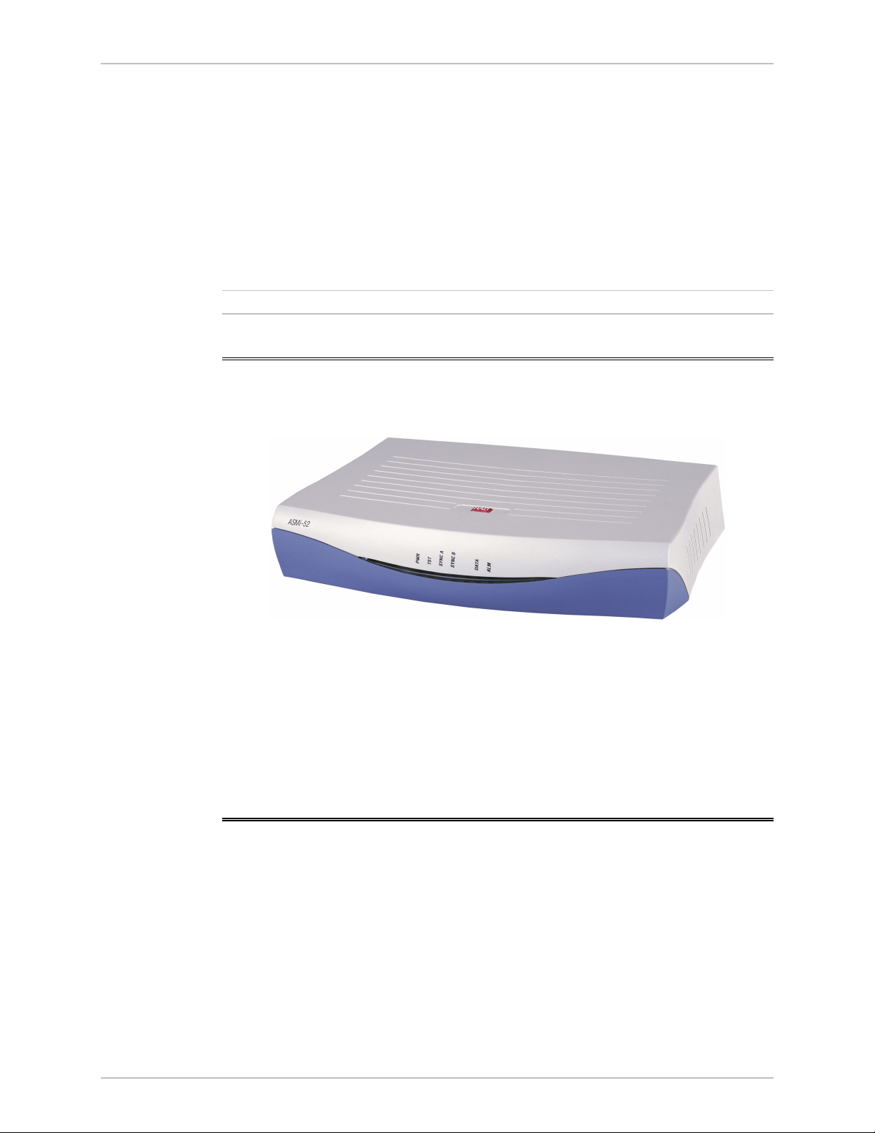
Chapter 1 Introduction Installation and Operation Manual
Statistics Collection
ASMi-52 supports SHDSL and E1/T1 statistics collection.
Alarm Reporting
ASMi-52 alarms are relayed via a dedicated 6-pin terminal block connector.
SHDSL Repeaters
Up to eight SHDSL repeaters can be installed in line to increase the operation
range of the modem. ASMi-52 provides basic management of the repeaters.
Not
SHDSL repeaters do not support ASMi-52 T1 products.
1.2 Physical Description
Figure 1-4 shows a 3D view of the ASMi-52 unit in the plastic enclosure.
Figure 1-4. ASMi-52, 3D View
The front panel includes several LEDs, which display the status of power, data flow
and provide diagnostics. For a detailed description of the front panel, see
Chapter 3.
The rear panel includes an AC/DC power connector, a DTE connector, a line
connector, a 10/100BaseT port, a V.24 terminal connector, and an alarm relay
port. The ASMi-52 rear panel is described in greater detail in Chapter 2.
1.3 Functional Description
This section provides a functional description of ASMi-52 in the form of block
diagrams (Figure 1-5 and Figure 1-6).
1-10 Functional Description ASMi-52 Ver. 2.5
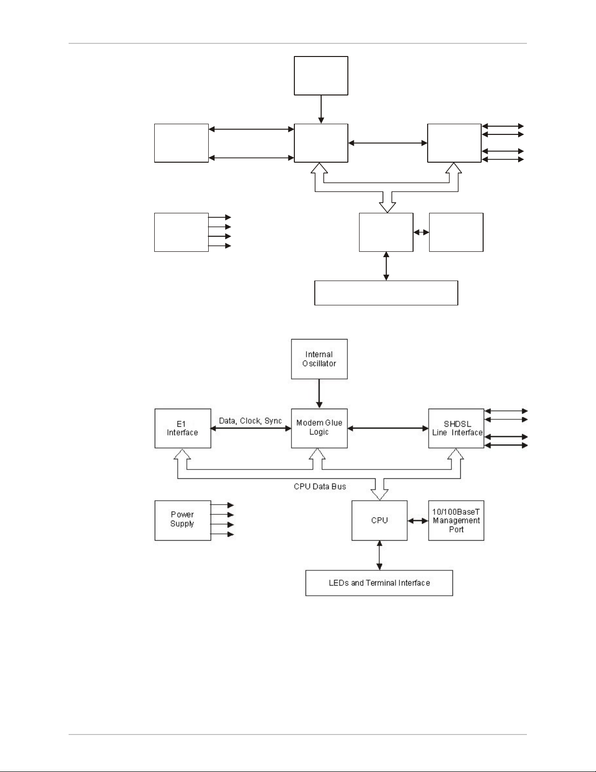
Installation and Operation Manual Chapter 1 Introduction
Internal
Oscillator
Data & Clock
DTE
Interface
Control Signals
Modem Glue
Logic
SHDSL
Line Interface
CPU Data Bus
Power
Supply
CPU
LEDs and Terminal Interface
10/100BaseT
Management
Port
Figure 1-5. ASMi-52/4W with V.35 Interface and 10/100BaseT Management Port
Figure 1-6. ASMi-52/4W with Framed E1 Interface and 10/100BaseT Management
Port
The ASMi-52 modem consists of the following major modules:
DTE interface – Prepares the digital data coming from the DTE into a data stream
for modem glue logic. In addition, it translates the data from the
modem glue logic into digital data to be sent to the DTE.
ASMi-52 Ver. 2.5 Functional Description 1-11

Chapter 1 Introduction Installation and Operation Manual
Internal oscillator – Serves as a source of internal clock for the ASMi-52 unit.
Modem glue logic module – Processes the data from/to the SHDSL interface
module.
SHDSL line interface – Translates the received and transmitted data from the line
to the DTE interface.
Power supply – Provides 2.5V, 3.3V, 5V and -5V to the ASMi-52 internal
elements.
CPU – Controls the ASMi-52 operation.
10/100BaseT management port – Provides LAN connection to the SNMP
management station or Telnet host.
LEDs and terminal interface – Provides modem status information via LED
indicators on the front panel, and communicates with the
supervisory terminal.
1.4 Technical Specifications
Line Interface
DTE Interface
Type
Line Coding
Range
Impedance
Connectors
Standard
E1 Jitter
Performance
Protection
Data Rate
2/4-wire unconditioned dedicated line (twisted pair)
TC-PAM
See Table 1-1
135Ω
• ASMi-52: RJ-45
• ASMi-52CD: Two RJ-45
ITU-T 991.2, ETSI 101 524
As per ITU G.823
ITU K.21, UL1950
Depends on the DTE/line interface type and clock mode
(see Table 1-2 and Table 1-3)
• 2-wire (external clock): 64–2304 kbps,
2-wire (internal clock): 64–2048, 2304 kbps
• 4-wire (external clock): 64–4608 kbps,
4-wire (internal clock): 64–4096, 4608 kbps
• ASMi-52CD/4W:
(external clock): 128-4608 kbps
(internal clock): 128-4096, 4608 kbps
1-12 Technical Specifications ASMi-52 Ver. 2.5
Coding
Line Impedance
• E1: HDB3
• T1: B8ZS or AMI
• E1: 120Ω, balanced
75Ω, unbalanced (via adapter cable)

Installation and Operation Manual Chapter 1 Introduction
• T1: 100Ω, balanced
Management
Ports
Connector Type
V.24/RS-232
Control Port
Interface
Connector
Format
Baud Rate
Ethernet Port
• X.21: 15-pin, D-type, female
• V.35 – 34-pin, female
• RS-530 – 25-pin, D-type, female
• G.703/G.704 E1 – RJ-45, balanced or unbalanced (via
adapter cable)
• T1 – RJ-45
• IR-IP (IP router) – RJ-45
• Ethernet (10/100BaseT bridge with VLAN support) –
RJ-45
V.24/RS-232 DTE
9-pin D-type, female
Asynchronous
9.6 to 115.2 kbps
Timing
Diagnostics
Interface
Connector
Loopbacks
Performance
Monitoring
10/100BaseT
RJ-45 shielded
Derived from three alternative sources:
• Internal oscillator
• External, from the attached DTE
• Receive, derived from the received signal
ITU V.54:
• Local analog loopback, activated via the management
software or by the DTE interface signal (V.35 and RS530 only)
• Remote digital loopback, activated via the
management software or by the DTE interface signal
(V.35 and RS-530 only)
• Remote loopback at the SHDSL repeater
• SHDSL statistics collection
• E1 with CRC-4 or T1 with ESF framing per ITU G.706
• E1 without CRC-4 or T1 with SF framing bipolar
violations (BPV)
ASMi-52 Ver. 2.5 Technical Specifications 1-13

Chapter 1 Introduction Installation and Operation Manual
Alarm Relay
Indicators
Physical
Operation
Connector
PWR (green)
TEST (red)
SYNC A/B
(green/red)
DATA (yellow)
E1/T1 SYNC (red)
AIS (yellow)
ALM (red)
Plastic Enclosure
Height
Width
Depth
Normally Open and Normally Closed, using different
pins
Terminal block, 6-pin
Power
Test
Synchronization of DSL line
Data Transfer (except E1 and T1 options)
Loss of E1/T1 synchronization (E1 and T1 options only)
“All 1s string” is received (E1 or T1 interface only)
Alarm
43.7 mm (1.7 in)
217 mm (8.5 in)
170 mm (6.7 in)
Power Source
Weight
Metal Enclosure
Height
Width
Depth
Weight
Rail-Mount Metal
Enclosure
Height
Width
Depth
Weight
AC/DC Voltage
0.5 kg (1.1 lb)
47.3 mm (1.8 in)
215 mm (8.4 in)
147 mm (5.8 in)
0.7 kg (1.5 lb)
150 mm (5.9 in)
70 mm (2.7 in)
160 mm (6.3 in)
0.75 kg (1.65 lb)
Wide range power supply:
100–240 VAC or -48/60 VDC nominal
DC only:
24 VDC
1-14 Technical Specifications ASMi-52 Ver. 2.5
Power
Consumption
2-wire: 6W max
4-wire: 7W max
Loading…
-
Страница 1
Installation and Operation Manual AS M i — 5 2 2 /4-Wire SHDSL Modem Version 2.5[…]
-
Страница 2
[…]
-
Страница 3
ASMi-52 Version 2.5 2/4-Wire SHDSL Modem Installation and Operation Manual Notice T h i s m a n u a l c o n t a i n s i n f o r m a t i o n t h a t i s p r o p r i e t a r y t o R A D D a t a C o m m u n i c a t i o n s L t d . ( » R A D » ) . N o part of this publication may be reproduced in any form whatsoever without prior written appr[…]
-
Страница 4
Limited Warranty RAD warrants to DISTRIBUTOR that the hardware in the A SMi- 52 to be de livered hereunder s hall be free of defects in material and workmanshi p under no rmal use and service for a period of twelve (12) months following the date of shipment to DISTRIBUTOR. If, during the warranty period, any component part of the equipment becomes […]
-
Страница 5
General Safety Instructions The following in structions ser ve as a general guid e for the safe installation and op eration of telecommunications products. Addition al i nstructions, if appl icable, are included ins ide the manual. Safety Symbols This symbol may appear on the equipment or in the text. It indicates potential safety hazards regarding[…]
-
Страница 6
Handling Energized Products General Safety Practices Do not touch or tamper with the power supply when the power cord is connecte d. Line voltages may be present inside certain product s even wh en the power switch (if installed) is in the OFF position or a fuse is blown. For DC-powered products, alth ough the voltages levels are usua lly not hazar[…]
-
Страница 7
Connection of Data and Telecommunications Cables Data and telecommunicatio n interfaces are classified accor ding to their safety status. The following table list s the status of several standard in terfaces. If the st atus of a given port differs from the standard one, a no tice will be given i n the manual. Ports Safety Status V.11, V.28, V.35, V[…]
-
Страница 8
To reduce the risk of fire, use only No. 26 AWG or larger telecommunication line cords. Pour réduire les risques s’incendie, utiliser seulement des conducteurs de télécommunications 26 AWG ou de section supérieure. Some ports are suitable for connection to intra-buildin g or non-exposed wiring or cabling only. In such cases, a notice will be […]
-
Страница 9
Canadian Emission Requirements This Class A digital apparatus meets all the requirements of the Canadian Interference-Causing Equipment Regulation. Cet appareil numérique de la classe A respecte to utes les exigences du Règlement sur le matériel brouilleur du Canada. Warning per EN 55022 (CISPR- 22) This is a class A product. In a domestic envir[…]
-
Страница 10
Declaration of Conformity Manufacturer’s Name: RAD Data Communications Ltd. Manufacturer’s Address: 24 Raoul Wallenberg St. Tel Aviv 69719 Israel declares that the product: Product Name: ASMi-52 Conforms to the following standard(s ) or other normative document(s): EMC: EN 55022: 1994 Limits and methods of measurement of radio disturbance[…]
-
Страница 11
ASMi-52 Ver. 2.5 Configuring ASMi-52 1 Quick Start Guide Installation of ASMi-52 should be carried out only by an experienced technician. If you are familiar with ASMi-52, use this gu ide to prepare the units for operation. 1. Installing ASMi-52 Connecting the Interfaces 1. Connect the line to the RJ-45 re ar panel connector dedicated SHDSL. 2. Con[…]
-
Страница 12
Quick Start Guide Installation and Operation Manual 2 Configuring ASMi-52 ASMi-52 Ver. 2.5 Configuring the Master Cloc k To configure the master clock: • From the System Configuration menu (Main Menu > Configurat ion > System Configuration > Ma ster Clock), configure the central ASMi-52 clock to external or internal and remote AS Mi-[…]
-
Страница 13
Installation and Operation Manual Quick Start Guide ASMi-52 Ver. 2.5 Configuring ASMi-52 3 To configure E1 parameters: • From the E1 Port Configuration menu (Main Menu > Configuration > Port Configuration > E1 Port Configuration), configure the following E1 parameters: Framing mode Timeslot assignment • You can configure ti[…]
-
Страница 14
Quick Start Guide Installation and Operation Manual 4 Configuring ASMi-52 ASMi-52 Ver. 2.5[…]
-
Страница 15
ASMi-52 Installation and Operation Manual i Contents Chapter 1. Introduction 1.1 Overview ……………………………………………………………………………………………………… 1-1 Versio ns ……………………………………………………………………………………………………….. ……..[…]
-
Страница 16
Table of Contents ii ASMi-52 Installation and Operation Manual Setting the G.704 Interfac e Type …………………………………………………………………………….. 4-21 4.3 Configuring the Physical P orts ………………………………………………………………………… 4-22 Configuring the SH DSL Interface[…]
-
Страница 17
ASMi-52 Ver. 2.5 Overview 1-1 Chapter 1 Introduction 1.1 Overview ASMi-52 is an SHDSL mo dem that operates in full- duplex over 2/4-wire lines an d offers a cost-effective solution for delivering digital data to customer pre mises over existing copper cables. AS Mi-52 handl es multiple data rates in the range of 64–4608 kbps. The unit is availabl[…]
-
Страница 18
Chapter 1 Introduction Installation and Operation Manual 1-2 Overview ASMi-52 Ver. 2.5 Unit Enclosure ASMi-52 is available in a plastic, metal, or rail-mount enclosure. Applications Figure 1-1 illustrates a typ ical ASMi-52 application, in which standalone modems operate opposite each other. Figure 1-2 shows ASMi- 52 units operating op posite a cen[…]
-
Страница 19
Installation and Operation Manual Chapter 1 Introduction ASMi-52 Ver. 2.5 Overview 1-3 Figure 1-2. ASMi-52 Mo dems Operating O pposite a Centrall y Located LRS-24 Rack Figure 1-3. ASMi-5 2 Modems Op erating opposite ASMi-52CD Cards[…]
-
Страница 20
Chapter 1 Introduction Installation and Operation Manual 1-4 Overview ASMi-52 Ver. 2.5 Features Functionality ASMi-52 can be configured to operate in a CO (central office) or CPE (custo mer premises equipment) mode. Line Interface ASMi-52 extends the ran ge of data transmission ov er 2/4-wire lines up to 7.0 km (4.3 miles), by employing SHDSL TC-P […]
-
Страница 21
Installation and Operation Manual Chapter 1 Introduction ASMi-52 Ver. 2.5 Overview 1-5 DTE Interface ASMi-52 supports the following DTE interfaces: • X.21 • V.35 • RS-530 • E1, as per G.704 • T1 • Ethernet/Fast Ethernet bridge with VLAN support (combined with man agement LAN port) • IR-IP (IP router). When ASMi-52 is ordere d only wit[…]
-
Страница 22
Chapter 1 Introduction Installation and Operation Manual 1-6 Overview ASMi-52 Ver. 2.5 Table 1-2. ASMi-52 D ata Rates DTE Interface and Clock Mode Line Interface Local ASMi-52 Remote ASMi-52 2-wire 4-wire Serial DTE interface, internal clock Serial DTE interface n × 64 kbps (n = 1, 2, … 32, 36) n × 128 kbps ( n = 1, 2, …32, 36) Serial DTE int[…]
-
Страница 23
Installation and Operation Manual Chapter 1 Introduction ASMi-52 Ver. 2.5 Overview 1-7 Multiplexer Applications • The multiplexer unit cannot be configured as a device with L AN only port. It must have a DTE or IR port. • The hardware of a single unit-based pr oduct with a LAN port ma nager is different from that of a mu ltiplexer-based product[…]
-
Страница 24
Chapter 1 Introduction Installation and Operation Manual 1-8 Overview ASMi-52 Ver. 2.5 Table 1-4. Possible Mu ltiplexer Applications (Cont.) CO/CPE E1 Serial DTE LAN E1+Serial DTE E1+LAN Serial DTE+LAN E1 ↔ E1 E1 ↔ Serial DTE E1 ↔ LAN E1 ↔ E1+Serial DTE E1 ↔ E1 E1 ↔ Serial DTE E1+LAN ↔ E1 E1 ↔ E1 E1 ↔ Serial DTE E1 ↔ E1+LAN E1 ?[…]
-
Страница 25
Installation and Operation Manual Chapter 1 Introduction ASMi-52 Ver. 2.5 Overview 1-9 • Receive, recovered from the received line signal (CPE mode). Management ASMi-52 supports the following management options: • ASCII terminal or Easy Config hand-hel d device via V.24/RS-232 terminal port • Telnet via a dedicated 10/100BaseT port • SNMP n[…]
-
Страница 26
Chapter 1 Introduction Installation and Operation Manual 1-10 Functional Description ASMi-52 Ver. 2.5 Statistics Collection ASMi-52 supports SHDSL and E1/T1 statistics collection. Alarm Reporting ASMi-52 alarms are relayed via a dedi cated 6-pin terminal block connector. SHDSL Repeaters Up to eight SHDSL repeaters can be installed in l ine to incre[…]
-
Страница 27
Installation and Operation Manual Chapter 1 Introduction ASMi-52 Ver. 2.5 Functional Description 1-11 Modem Glue Logi c Data & Clock LED s an d T erm i na l I nt er fa c e Con trol S ignal s CPU 10/ 100B as eT Ma nage ment Por t CPU Data Bus DTE Interfa ce SHDSL Li ne I nt erf ac e Power Supp ly Internal Oscill ator Figure 1-5. ASMi-52/ 4W with[…]
-
Страница 28
Chapter 1 Introduction Installation and Operation Manual 1-12 Technical Specifications ASMi-52 Ver. 2.5 Internal oscillator – Serves as a source of internal clock for the ASMi-52 unit. Modem glue logic module – Processes the data from/to the SH DSL interface module. SHDSL line interface – Translates the received and transmitted data from the […]
-
Страница 29
Installation and Operation Manual Chapter 1 Introduction ASMi-52 Ver. 2.5 Technical Specifications 1-13 • T1: 100 Ω , balanced Connector Type • X.21: 15-pin, D-type, female • V.35 – 34-pin, female • RS-530 – 25-pin, D-type, female • G.70 3/G.704 E1 – RJ-45, balanced or unbalanced ( via adapter cable) • T1 – RJ-45 • IR-IP ( I[…]
-
Страница 30
Chapter 1 Introduction Installation and Operation Manual 1-14 Technical Specifications ASMi-52 Ver. 2.5 Alarm Relay Operation Normally Open and Normally Closed, using different pins Connector Terminal block, 6-pin Indicators PWR (green) Power TEST (red) Test SYNC A/B (green/red) Synchronization of DSL line DATA (yellow) Data Transfer (except E1 and[…]
-
Страница 31
Installation and Operation Manual Chapter 1 Introduction ASMi-52 Ver. 2.5 Technical Specifications 1-15 Environment Temperature Standalone: 0 ° to 50 ° C (32 ° to 122 ° F) Rail-mount: − 20 ° to 70 ° C ( − 4 ° to 158 ° F) Humidity Up to 90%, non–condensing Shock (Rail-Mount) IEC 60068-2-27 shock 1 5g, 11 ms duration, 18 shocks Vibratio[…]
-
Страница 32
Chapter 1 Introduction Installation and Operation Manual 1-16 Technical Specifications ASMi-52 Ver. 2.5[…]
-
Страница 33
ASMi-52 Ver. 2.5 Site Requi rements and Prerequisites 2-1 Chapter 2 Installation and Setup 2.1 Introduction This chapter describes installation and setup procedures for the standalone ASMi-52 modem. After installing the unit: • Refer to Chapter 3 for the operating instructions. • Refer to Chapter 4 for the detailed system conf igura tion proced[…]
-
Страница 34
Chapter 2 Installation and Setup Installation and Operation Manual 2-2 Connecting the Interface Cables ASMi-52 Ver. 2.5 Allow at least 90 cm (36 in) of fronta l clearance for operation and maintenance accessibility. Allow at least 10 cm (4 in) cl earance at the rear of the unit for signal lines and interface cables. The ambient operating temperatur[…]
-
Страница 35
Installation and Operation Manual Chapter 2 Installation and Setup ASMi-52 Ver. 2.5 Connecting the Power Cables 2-3 Connecting the Line The ASMi-52 line interface terminates in an 8-pin RJ-45 connector. To connect the line connector: • Connect the line cable to the RJ -45 connector designated SHDSL. Connecting the DTE Interface The ASMi-52 DT[…]
-
Страница 36
Chapter 2 Installation and Setup Installation and Operation Manual 2-4 Connecting the Power Cables ASMi-52 Ver. 2.5 Before connecting this unit to a powe r source and connecting or disconnecting any other cable, the protective earth terminals of this unit must be conn ected to the protective ground conductor of the mains (AC or DC) power cord. If y[…]
-
Страница 37
ASMi-52 Ver. 2.5 Controls and Indicators 3-1 Chapter 3 Operation This chapter provides the following information for the ASMi-52 modem: • ASMi-52 front-panel indicators • Operating procedures (turn-on, fron t-panel indications, performance monitoring and turn-off) • ASMi-52 default settings. Installation procedures giv en in Chapter 2 mu st b[…]
-
Страница 38
Chapter 3 Operation Installation and Operation Manual 3-2 Controls and Indicators ASMi-52 Ver. 2.5 ASMi-5 2 Figure 3-1. ASMi-52 Fr ont Panel, E1 Interface (2 Wire ) Figure 3-2. ASMi-52 Fr ont Panel, E1 Interface (4 Wire ) Figure 3-3. ASMi-52 Fr ont Panel, T1 Interface (4 Wir e) ASMi-5 2 Figure 3-4. ASMi-52 Front Panel, DTE Serial Interface (4 Wire)[…]
-
Страница 39
Installation and Operation Manual Chapter 3 Operation ASMi-52 Ver. 2.5 Controls and Indicators 3-3 Table 3-1. ASMi-52 Front Panel LEDs Name Function PWR (green) On – Power is ON TST (red) On – A loopback test is active in a local or remote unit SYNC A (red/green) On (red) – Link A is not synchronized On (green) – Link A is synchronized Blin[…]
-
Страница 40
Chapter 3 Operation Installation and Operation Manual 3-4 Default Settings ASMi-52 Ver. 2.5 3.3 Default Settings ASMi-52 is managed by an ASCII ter minal or a PC running a terminal emulation program via a menu-driv en embedded so ftware. Table 3-4 lists the default settings of the ASMi-52 conf iguration parameters. Table 3-4. Default Settings Param[…]
-
Страница 41
Installation and Operation Manual Chapter 3 Operation ASMi-52 Ver. 2.5 Default Settings 3-5 Parameter Default Value Control Port Control port rate 9600 bps Data 8 Parity None Interface DCE CTS =RTS DSR ON Port control mode Terminal User name – Password 1234 Pop alarm OFF Security timeout 10 min Call Out Mode None Number of retries 1 Wait for conn[…]
-
Страница 42
Chapter 3 Operation Installation and Operation Manual 3-6 Configuration Alternatives ASMi-52 Ver. 2.5 Parameter Default Value Serial DTE Interface Rate Single: 2-wire – 192 kbps 4-wire – 384 kbps Multiplexer: 1. E1+Serial DTE, N/A , 0 kbps 2. LAN+Serial DTE: 2-wire – 192 kbps 4-wire – 384 kbps LLB from DTE Disable RLB from DTE Disable E1/E1[…]
-
Страница 43
Installation and Operation Manual Chapter 3 Operation ASMi-52 Ver. 2.5 Configur ation Alternatives 3-7 • Remote management via out-of- band 10/1 00BaseT port or dedi cated timeslot. Remote management is p erformed us ing Telnet, or ConfiguR AD (RAD’s Web-based application), or RADvie w (RAD’s SNMP -based management system). Managing ASMi-52 v[…]
-
Страница 44
Chapter 3 Operation Installation and Operation Manual 3-8 Configuration Alternatives ASMi-52 Ver. 2.5 3. Configure the terminal to the defa ult communication para meters: 9.6 kbps, one start bit, eight data bits, no parity, one stop bit, VT100 e mulation. 4. Select the full duplex mo de. 5. Turn the terminal echo off. 6. Disa ble any type of flow c[…]
-
Страница 45
Installation and Operation Manual Chapter 3 Operation ASMi-52 Ver. 2.5 Configur ation Alternatives 3-9 Managing ASMi-52 via Ethernet Port ASMi-52 is equipped with an Etherne t/Fast Ethernet port (10/100BaseT) which enables communication with ASMi-52 management subs ystem using the IP protocol (see Figure 3-9 ). The Ethernet management port is confi[…]
-
Страница 46
Chapter 3 Operation Installation and Operation Manual 3-10 Configuration Alternatives ASMi-52 Ver. 2.5 session over the dedicated timeslot ha s priority ove r management via the 10/100BaseT port. 1. Connect the E1/T1 line to the ASMi-52 E1 or T1 port. 2. Start a terminal management sess ion and do the following: Assig n an IP address and an IP […]
-
Страница 47
Installation and Operation Manual Chapter 3 Operation ASMi-52 Ver. 2.5 Configur ation Alternatives 3-11 • Trace – opens an additional pane for s ystem messages, progress indicators (ping, software and co nfiguration fi le downloads) and alarms. It is recommended to keep the trace pane open all the time. • Refresh All – refreshes all screen […]
-
Страница 48
Chapter 3 Operation Installation and Operation Manual 3-12 Configuration Alternatives ASMi-52 Ver. 2.5 Figure 3-10. Inventory and Configurati on Menus[…]
-
Страница 49
Installation and Operation Manual Chapter 3 Operation ASMi-52 Ver. 2.5 Configur ation Alternatives 3-13 Figure 3-11. Monitoring, Diagno stics and File Utilities Menus[…]
-
Страница 50
Chapter 3 Operation Installation and Operation Manual 3-14 Turning Off ASMi-52 ASMi-52 Ver. 2.5 Logging Out To end the current session: • In the Main m enu, click Logout or type & in a terminal management screen. • • ASMi-52 allo ws at least four management se ssions to be active at a time. If the Web-based management sessi ons were n[…]
-
Страница 51
ASMi-52 Ver. 2.5 Configuring ASMi-52 for Management 4-1 Chapter 4 Configuration 4.1 Configuring ASMi-52 for Management The configuration of ASMi-52 is performed via a menu-dr iven embedded software, using a standard ASCII terminal or a PC running a terminal emulat ion application connected to the rear panel CONTROL port. Altern atively, ASMi-52 can[…]
-
Страница 52
Chapter 4 Configuration Installation and Operation Manual 4-2 Configuring ASMi-52 for Management ASMi-52 Ver. 2.5 Entering Device Information The Device Information menu allows you to assign a name to ASMi-52, define its location, and contact person. These entries may include up to 20 characters. To enter device information: 1. Display the Sys […]
-
Страница 53
Installation and Operation Manual Chapter 4 Configuration ASMi-52 Ver. 2.5 Configuring ASMi-52 for Management 4-3 Configuring the Host Parameters ASMi-52 can be managed by a netw ork management station, w hich is located on the LAN connected to the 10/100BaseT po rt. In order to establish a pro per connection, it is necessary to configure the follo[…]
-
Страница 54
Chapter 4 Configuration Installation and Operation Manual 4-4 Configuring ASMi-52 for Management ASMi-52 Ver. 2.5 3. Type a nu mber corresponding to a subnet mask of t he already defined network management station, and ente r a new value. 4. Repeat step 2 an d step 3 to defi ne addit ional management stations. 5. Press <Esc> to return to the […]
-
Страница 55
Installation and Operation Manual Chapter 4 Configuration ASMi-52 Ver. 2.5 Configuring ASMi-52 for Management 4-5 ASMi-52 Management Access 1. TELNET allowed (access allowed) 2. WEB allowed (access allowed) > ESC-prev. menu; !-main menu; &-exit; @-scroll Figure 4-6. Mana gement Access Menu Configuring Dedicated Timeslots ASMi-52 units with a[…]
-
Страница 56
Chapter 4 Configuration Installation and Operation Manual 4-6 Configuring ASMi-52 for Management ASMi-52 Ver. 2.5 ASMi-52 Rem Agent Table SOURCE IP DESTINATION IP PORT > ESC-prev. menu; !-main menu; &-exit; @-scroll; ?-help Figure 4-8. R em Agent Table Configuring VLAN Encapsulation ASMi-52 is occasionally connected to a VLAN network when ma[…]
-
Страница 57
Installation and Operation Manual Chapter 4 Configuration ASMi-52 Ver. 2.5 Configuring ASMi-52 for Management 4-7 Configuring the LAN Port ASMi-52 includes a 10/100BaseT port that can be used as a user or management port. The LAN port operates in a self-learning bridge or transparent mode, w ith or without autonegotiation. • If the LAN port serve[…]
-
Страница 58
Chapter 4 Configuration Installation and Operation Manual 4-8 Configuring ASMi-52 for Management ASMi-52 Ver. 2.5 Filling out the Bridging Table When the 10/100BaseT port operates in the bridge mode, yo u can assign MAC addresses to the local or remote LAN. To fill out the bridge table: 1. Select Bridging Table from the Local LAN Config uration[…]
-
Страница 59
Installation and Operation Manual Chapter 4 Configuration ASMi-52 Ver. 2.5 Configuring ASMi-52 for Management 4-9 ASMi-52 Bridge Table Type (Static) 1. MAC Address … (00000000000) 2. Port … () > ESC-prev. menu; !-main menu; &-exit; ?-help Figure 4-12. Bridge Table, Editing Mode Configuring Aging Timeout The aging time is the timeout peri[…]
-
Страница 60
Chapter 4 Configuration Installation and Operation Manual 4-10 Configuring ASMi-52 for Management ASMi-52 Ver. 2.5 ASMi-52 QoS Mapping (Classification 802.1p) 1. User Priority 0 > (Traffic Class 0) 2. User Priority 1 > (Traffic Class 0) 3. User Priority 2 > (Traffic Class 0) 4. User Priority 3 > (Traffic Class 0) 5. User Priority 4 >[…]
-
Страница 61
Installation and Operation Manual Chapter 4 Configuration ASMi-52 Ver. 2.5 Configuring ASMi-52 for Management 4-11 ASMi-52 Data Rate (2304 Kbps) 1. 64 Kbps 12. 768 Kbps 23. 1472 Kbps 2. 128 Kbps 13. 832 Kbps 24. 1536 Kbps 3. 192 Kbps 14. 896 Kbps 25. 1600 Kbps 4. 256 Kbps 15. 960 Kbps 26. 1664 Kbps 5. 320 Kbps 16. 1024 Kbps 27. 1728 Kbps 6. 384 Kbp[…]
-
Страница 62
Chapter 4 Configuration Installation and Operation Manual 4-12 Configuring ASMi-52 System Parameters ASMi-52 Ver. 2.5 2. If the autonegotiation is e nabled, choose Max AutoNeg Capabil ity from the Local LAN Configuration menu. The Set Capability menu appears. 3. Select the required LAN operation mo de by choosing one o f the following: 10BaseT […]
-
Страница 63
Installation and Operation Manual Chapter 4 Configuration ASMi-52 Ver. 2.5 Configuring AS Mi-52 System Parameters 4-13 ASMi-52 Configuration > 1. System configuration > 2. LAN configuration > 3. SHDSL configuration 4. E1 configuration 5. T1 configuration 6. DTE configuration > ESC-prev. menu; !-main menu; &-exit; @-scroll Figure 4-1[…]
-
Страница 64
Chapter 4 Configuration Installation and Operation Manual 4-14 Configuring ASMi-52 System Parameters ASMi-52 Ver. 2.5 Configuring the Master Cloc k ASMi-52 modems support receive, exte rnal and internal clock modes. When configured to the internal or extern al clock, ASMi-52 modem operates as a n STU-C unit. When configured to the receive clock, AS[…]
-
Страница 65
Installation and Operation Manual Chapter 4 Configuration ASMi-52 Ver. 2.5 Configuring AS Mi-52 System Parameters 4-15 ASMi-52 Local/Remote Card Mode 1. E1 2. DTE 3. E1 + LAN 4. E1 + V35 5. V35 + LAN > ESC-prev. menu; !-main menu; &-exit; @-scroll Figure 4-19. Local/Remote Card Mode Menu Configuring Remote Ca rd Mode The remote card mode con[…]
-
Страница 66
Chapter 4 Configuration Installation and Operation Manual 4-16 Configuring ASMi-52 System Parameters ASMi-52 Ver. 2.5 Configuring Control Port Pa rameters The embedded ASMi-52 software enables you to c onfigure the Control port parameters. To access the Control port menu: • From the System Configuration menu, select Control Port (Main menu &g[…]
-
Страница 67
Installation and Operation Manual Chapter 4 Configuration ASMi-52 Ver. 2.5 Configuring AS Mi-52 System Parameters 4-17 Selecting the Contro l Por t Interfa ce To select the control port interface: 1. From the Control Port menu, select Interface (Main menu > Configuration > System Configuration > Control Port > Interface) to choose t[…]
-
Страница 68
Chapter 4 Configuration Installation and Operation Manual 4-18 Configuring ASMi-52 System Parameters ASMi-52 Ver. 2.5 ASMi-52 Port Control 1. Port Control Mode > (Terminal) 2. Terminal > 3. Dial out > 4. Save > ESC-prev. menu; !-main menu; &-exit; @-scroll Figure 4-22. Port Control Menu Configuring the Port Control Mode The Control […]
-
Страница 69
Installation and Operation Manual Chapter 4 Configuration ASMi-52 Ver. 2.5 Configuring AS Mi-52 System Parameters 4-19 ASMi-52 Terminal 1. Change access > 2. POP ALARM (No) 3. Security timeout (10 min) 4. Save > ESC-prev. menu; !-main menu; &-exit; @-scroll Figure 4-24. Terminal Menu To change the user name and password: 1. From t he […]
-
Страница 70
Chapter 4 Configuration Installation and Operation Manual 4-20 Configuring ASMi-52 System Parameters ASMi-52 Ver. 2.5 To configure the security timeout: 1. From t he Terminal menu, select Security Timeout (Main menu > Configuration > System Configuratio n > Control Port > Port Control > Terminal > Security Timeout) to configur[…]
-
Страница 71
Installation and Operation Manual Chapter 4 Configuration ASMi-52 Ver. 2.5 Configuring AS Mi-52 System Parameters 4-21 3 to specify the time (in sec) ASMi-52 waits for an answer after each dial ing attempt. If the called station does not answer within the specified time, ASMi-52 disconnects. If addition al call attempts are allowed, ASMi-52 red[…]
-
Страница 72
Chapter 4 Configuration Installation and Operation Manual 4-22 Configuring the Physical Ports ASMi-52 Ver. 2.5 4.3 Configuring the Physical Ports Configuring the SHDSL Interface The ASMi-52 configuration soft ware allows you to c hange the modem’s transmission mode (A nnex A or Annex B). Examples given below illustrate the lo cal device configura[…]
-
Страница 73
Installation and Operation Manual Chapter 4 Configuration ASMi-52 Ver. 2.5 Configuring the Physical Ports 4-23 ASMi-52 SHDSL remote port configuration Transmission mode (Annex_AB) Asym PSD (Asym/Sym Enable) Line prob (Adaptive rate) 1. Power backoff (Enable) 2. Snext margin (Disable Snext margin) 3. Current margin (Disable current margin) 4. Loop a[…]
-
Страница 74
Chapter 4 Configuration Installation and Operation Manual 4-24 Configuring the Physical Ports ASMi-52 Ver. 2.5 2. Select the Snext margin by typing th e number corresponding to the required value. The SHDSL Remote Port menu appears. 3. Select Save to save the changes. ASMi-52 Snext margin (Disable Snext margin) 1. -10 12. 1 2. -9 13. 2 3. -8 14. 3 […]
-
Страница 75
Installation and Operation Manual Chapter 4 Configuration ASMi-52 Ver. 2.5 Configuring the Physical Ports 4-25 Configuring the Power Spectral Density By configuring the power spectral dens ity, you define the amoun t of power applied to the spectrum of frequencies that carry the informat ion signal in order to achieve a satisfactory level of signal[…]
-
Страница 76
Chapter 4 Configuration Installation and Operation Manual 4-26 Configuring the Physical Ports ASMi-52 Ver. 2.5 Configuration > SHDSL Local Port/SHDSL Remote Port/SHDSL Repeater > Loop Attenuation Threshold). The loop attenuation threshold can be configured from the SHDSL remote or local port, or from the SHDSL repeater. 2. Enter the required […]
-
Страница 77
Installation and Operation Manual Chapter 4 Configuration ASMi-52 Ver. 2.5 Configuring the Physical Ports 4-27 Configuring the DTE Interface Data Rate ASMi-52 supports multiple data rate s between the range of 64 kbps and 4608 kbps, depending on the clock mode and line/DTE interface of the local and remote units (see Table 1-2 an d Table 1-3 ). […]
-
Страница 78
Chapter 4 Configuration Installation and Operation Manual 4-28 Configuring the Physical Ports ASMi-52 Ver. 2.5 Configuring the E1 Interface The following are commonly used acronyms: • CO – Central Office, where the clock sour ce is set to internal or external • CPE – customer premise equipment. When ASMi-52 includes a G.7 04 E1 port, you ca[…]
-
Страница 79
Installation and Operation Manual Chapter 4 Configuration ASMi-52 Ver. 2.5 Configuring the Physical Ports 4-29 ASMi-52 E1 Local Port 1. Framed mode (G732N) 2. Sync mode (CCITT(complies with G732)) 3. CRC-4 (NO) 4. Idle code (ff) 5. Time slots assign 6. Unit Identical Set (Yes) 7. Number TS for remote E1 8. Save > ESC-prev. menu; !-main menu; &am[…]
-
Страница 80
Chapter 4 Configuration Installation and Operation Manual 4-30 Configuring the Physical Ports ASMi-52 Ver. 2.5 ASMi-52 Framed mode (Unframed) 1. Unframed 2. G732N 3. G732S transparent > ESC-prev. menu; !-main menu; &-exit; @-scroll Figure 4-34. Framed Mode Menu Enabling CRC-4 Code Generation You have to enable the CRC-4 code generation if yo[…]
-
Страница 81
Installation and Operation Manual Chapter 4 Configuration ASMi-52 Ver. 2.5 Configuring the Physical Ports 4-31 ASMi-52 Sync mode (CCITT (complies with G732)) 1. FAST (after 1 sec) 2. 62411 (after 10 sec) 3. CCITT (complies with G732) > ESC-prev. menu; !-main menu; &-exit; @-scroll Figure 4-35. Sync Mode Menu Defining Idle Code You can define[…]
-
Страница 82
Chapter 4 Configuration Installation and Operation Manual 4-32 Configuring the Physical Ports ASMi-52 Ver. 2.5 • • You can configure timeslot 0 to be looped or transp arent: Looped – timeslot 0 is sent back to the E1 interface, when operating opposite remote units with a serial data interface. Transparent – timeslot 0 is tran smitte[…]
-
Страница 83
Installation and Operation Manual Chapter 4 Configuration ASMi-52 Ver. 2.5 Configuring the Physical Ports 4-33 ASMi-52 has a multiplexer mo dem with two interfa ces. The maximum timeslots that can be used are as follows: • If E1 + LAN, then the maximum TSs (t imeslots) = (2048 kbps – LAN rate) / 64 kbps. • If E1 + Serial DTE, then t he maximu[…]
-
Страница 84
Chapter 4 Configuration Installation and Operation Manual 4-34 Configuring the Physical Ports ASMi-52 Ver. 2.5 • The Unit Identical Set is permanently set to Yes, the parameters are copied to the remote unit. If the Frame Mode is not G732S: • The Unit Identical setting can be set to Yes or No when the local modem is configured as CO and both mo[…]
-
Страница 85
Installation and Operation Manual Chapter 4 Configuration ASMi-52 Ver. 2.5 Configuring the Physical Ports 4-35 • Transmit signal mask (DSU mode) – le ng th of a cable in feet between the ASMi-52 T1 port connector and the n etwork access point: 0 fe et – 0 to 133 feet 13 3 feet – 133 to 266 feet 26 6 feet — 266 to 399 feet 39[…]
-
Страница 86
Chapter 4 Configuration Installation and Operation Manual 4-36 Additional Tasks ASMi-52 Ver. 2.5 4.4 Additional Tasks Displaying the ASMi-52 Status The ASMi-52 software allows you to disp lay the modem system and physical port information. The status information is a vailable via the Monitoring menu. To access the Monitoring menu: • From the […]
-
Страница 87
Installation and Operation Manual Chapter 4 Configuration ASMi-52 Ver. 2.5 A dditional Tasks 4-37 ASMi-52 System Status Local Remote Device Type (ASMi52_SA_M (PLASTIC)-STU_C-2W) ASMi52_SA Clock Source (INT) RCV Software Version (2.01E24) (2.01E24) Hardware Version (0.00) (0.00) FPGA Version (0.13) (0.13) Hardware Status (NO HARDWARE FAILURE) (NO HW[…]
-
Страница 88
Chapter 4 Configuration Installation and Operation Manual 4-38 Additional Tasks ASMi-52 Ver. 2.5 • The physical port alarms are described in Chapter 5 . 2. Type N to display the next page. Accessing the Remote ASMi-52 Accessing the remote ASMi-52 is performe d using a virtual connection with your terminal physically connected to the local unit. ?[…]
-
Страница 89
Installation and Operation Manual Chapter 4 Configuration ASMi-52 Ver. 2.5 A dditional Tasks 4-39 Figure 4-42. Password Reques t Screen (ConfiguRAD Session) To enter the user name and password: 1. Type in your user name a nd press <Tab> . • You can leave the user name field empty (default), the default password is 12 34. 2. Type in your[…]
-
Страница 90
Chapter 4 Configuration Installation and Operation Manual 4-40 Additional Tasks ASMi-52 Ver. 2.5 Figure 4-44. Main Menu (ConfiguRAD Session) Displaying the ASMi-52 Inventory The ASMi-52 inventory displays in formation on the functional blocks of the local or remote modem. ASMi-52 consists of the following components: • SHDSL unit • DTE unit •[…]
-
Страница 91
Installation and Operation Manual Chapter 4 Configuration ASMi-52 Ver. 2.5 A dditional Tasks 4-41 ASMi-52 Inventory 1 Index 1001 Description RAD-local ASMi-52_M SHDSL modem Vendor type Contained in 0 Class 3 Rel pos 0 Name SHDSL modem HW ver 0.00 SW ver 1.00E54 ->> > ESC-prev. menu; !-main menu; &-exit; @-scroll; ?-help Figure 4-45. In[…]
-
Страница 92
Chapter 4 Configuration Installation and Operation Manual 4-42 Additional Tasks ASMi-52 Ver. 2.5 ASMi-52 TFTP TFTP status (No operation) TFTP error (No error) 1. TFTP IP server (172.17.160.103) 2. TFTP file name (201e24.img) 3. TFTP retry timeout (sec) [0-300] (15) 4. TFTP total timeout (sec) [0-4000] (1200) 5. Save 6. Transfer command > ESC — p[…]
-
Страница 93
Installation and Operation Manual Chapter 4 Configuration ASMi-52 Ver. 2.5 A dditional Tasks 4-43 For exit press Q(uit) If you press <Q> , ASMi-52 aborts the download process and displays Download failure. Press Esc to continue. message in addition to the previous display. • During the software installation, the TST in dicator blinks. 2. Se[…]
-
Страница 94
Chapter 4 Configuration Installation and Operation Manual 4-44 Additional Tasks ASMi-52 Ver. 2.5 5. From the TFTP menu, pe rform the foll owing steps: Select TFTP IP Server and enter the IP address of the TFTP server Select TFTP File N ame and enter the name of the software file (for example, 201e24.img ). Select TFTP Retry Timeo ut and[…]
-
Страница 95
Installation and Operation Manual Chapter 4 Configuration ASMi-52 Ver. 2.5 A dditional Tasks 4-45 ASMi-52 SW files Local Remote Software active version: (2.01E24) (2.02000) Software active partition: (0) (0) Code size: (813110) (813161) Date: (28-7-4) (2-8-4) Software backup version: (2.01E24) (2.01E11) Software backup partition: (1) (1) Code size:[…]
-
Страница 96
Chapter 4 Configuration Installation and Operation Manual 4-46 Additional Tasks ASMi-52 Ver. 2.5 Resetting to Default Settings You can reset the local or remote ASMi-52 to it s default settings. Resetting to the factory default does not affect the master clock setting. In addition, you can reset the local ASMi-52 without affecting it s ma nagement […]
-
Страница 97
Installation and Operation Manual Chapter 4 Configuration ASMi-52 Ver. 2.5 A dditional Tasks 4-47 2. From th e Reset menu, select Local Reset to reset the local modem or Remo te Reset to reset the remote device. The Local/Remote Reset menu appears (see Figure 4-51 ). 3. From the Local/Remote Reset menu, select Local/Remote Device Reset to perform t[…]
-
Страница 98
Chapter 4 Configuration Installation and Operation Manual 4-48 Additional Tasks ASMi-52 Ver. 2.5 ASMi-52 Repeater Reset 1. Repeater SHDSL line reset . . . 2. Repeater number > (1) > ESC-prev. menu; !-main menu; &-exit; @-scroll Figure 4-52. Repeater Reset Menu Exiting the Control Session You can exit the terminal control session any time […]
-
Страница 99
ASMi-52 Ver. 2.5 Overview 5-1 Chapter 5 Configuring a Typical Application 5.1 Overview This chapter provides detailed instr uctions for setting up t wo ASMi-52 modems i n a typical application. ASMi-52 configuration is performed via a men u-driven embedded software using a standard ASCII terminal or a PC r unning a terminal emulatio n application c[…]
-
Страница 100
Chapter 5 Configuring a Typical Ap plication Installation and Operation Manual 5-2 Configuring the ASMi-52 units ASMi-52 Ver. 2.5 5.2 Configuring the ASMi-52 units Two ASMi-52 units must be configured for this app lication. Both units have t he same configuration parameters, except for the host IP address and the master clock mode. To prepare a[…]
-
Страница 101
Installation and Operation Manual Chapter 5 Configuring a Typical Application ASMi-52 Ver. 2.5 Configur ing the ASMi-52 units 5-3 Set the CO ASMi- 52 unit clock to Internal. Set the CPE ASMi-52 unit clock to Receive. 3. Select Save to save the changes. To set the device host IP address: 1. Displa y the host IP menu (Mai n menu > Conf[…]
-
Страница 102
Chapter 5 Configuring a Typical Ap plication Installation and Operation Manual 5-4 Configuring the ASMi-52 units ASMi-52 Ver. 2.5 2. From t he Framed Mode menu, select Unframed to choose the unframed operation. The E1 Local Port menu appears. 3. Save the changes. After performing these config uration proc edures, the ASMi-52 units are ready to be c[…]
-
Страница 103
Installation and Operation Manual Chapter 5 Configuring a Typical Application ASMi-52 Ver. 2.5 Configur ing the ASMi-52 units 5-5 ASMi-52 DTE local port configuration > 1. LLB from DTE : (Enable/Disable) 2. RLB from DTE : (Enable/Disable) 3. Data rate : (1984 kbps) 4. Save > ESC-prev. menu; !-main menu; &-exit; @-scroll Figure 5-6. DTE Lo[…]
-
Страница 104
Chapter 5 Configuring a Typical Ap plication Installation and Operation Manual 5-6 Configuring the ASMi-52 units ASMi-52 Ver. 2.5[…]
-
Страница 105
ASMi-52 Ver. 2.5 Monitoring Performance 6-1 Chapter 6 Troubleshooting and Diagnostics This chapter describes the ASMi- 52 di agnostic funct ions, which include: • Status indications, alarms, power-up self-test • Statistics collection • Bit Error Rate Test (BERT) • Diagnostic tests (loopback s and LEDs test). 6.1 Monitoring Performance Displ[…]
-
Страница 106
Chapter 6 Troubleshooting and Diagnostics Installation and Operation Manual 6-2 Monitoring Performance ASMi-52 Ver. 2.5 2. From th e Physical Port Statistics menu, select SHDSL Port Performances to display the unit’s SDHSL statistics. The SDHSL Port Performances menu appears (see Figure 6- 2 ). ASMi-52 SHDSL Port Performances 1. SHDSL current per[…]
-
Страница 107
Installation and Operation Manual Chapter 6 Troubleshooting and Diagnostics ASMi-52 Ver. 2.5 Monitoring Performance 6-3 ASMi-52 SHDSL current day performances Local A Local B Remote A Remote B Port number (1) (1) (1) (1) 24 hour ES (1) (1) (1) (1) 24 hour UAS (1401) (1401) (1401) (1401) 24 hour SES (0) (0) (0) (0) 24 hour LOWS (0) (0) (0) (0) 24 ho[…]
-
Страница 108
Chapter 6 Troubleshooting and Diagnostics Installation and Operation Manual 6-4 Monitoring Performance ASMi-52 Ver. 2.5 ASMi-52 SHDSL all intervals local/remote performances … Line A Line B INT CRC LOSWS ES SES UAS CRC LOSWS ES SES UAS ESC-prev. menu; !-main menu; &-exit; ?-help; @-scroll Figure 6-5. S HDSL All Interv als Local/Remote Perform[…]
-
Страница 109
Installation and Operation Manual Chapter 6 Troubleshooting and Diagnostics ASMi-52 Ver. 2.5 Monitoring Performance 6-5 • For details on enabling th e CRC-4 function, refer to Chapter 4 . • For the details on configur ing T1 fr aming, refer to Configuring T1 I nterface in Chapter 4. Displaying the Current E1/T1 Statistics To display the cur[…]
-
Страница 110
Chapter 6 Troubleshooting and Diagnostics Installation and Operation Manual 6-6 Monitoring Performance ASMi-52 Ver. 2.5 ASMi-52 E1/T1 current day performance Local Remote Port number (1) No statistics collection ESC-prev. menu; !-main menu; &-exit; @-scroll Figure 6-9. E1/T1 Current Day Performances Screen Table 6-2. E1/T1 Statistic s Parameter[…]
-
Страница 111
Installation and Operation Manual Chapter 6 Troubleshooting and Diagnostics ASMi-52 Ver. 2.5 Monitoring Performance 6-7 Table 6-2. . E1 Statistics Parameters (C ont.) Display Description Range Current DM Number of degraded minutes in which the B ER exceeded 1 × 10 -6 . This value is updated every minute for 15-m inute interval or every 24 hours fo[…]
-
Страница 112
Chapter 6 Troubleshooting and Diagnostics Installation and Operation Manual 6-8 Handling Alarms ASMi-52 Ver. 2.5 Clearing the E1/T1 Statistics To clear E1/T1 statistics: • From the E1 Port Performances menu (see Figure 6-2 ), select E1 /T1 Clear Local Performances or E1 /T1 Clear Remote Performances (Main menu > Monitoring > Physical Po[…]
-
Страница 113
Installation and Operation Manual Chapter 6 Troubleshooting and Diagnostics ASMi-52 Ver. 2.5 Handling Alarms 6-9 Displaying All Alarms ASMi-52 allows you to displa y all alarms, irrespective of their origin (system or port). To display all alarms: 1. From the Main menu, select Monitoring . The Monitoring menu appears (see Figure 6-11 ). 2. From[…]
-
Страница 114
Chapter 6 Troubleshooting and Diagnostics Installation and Operation Manual 6-10 Handling Alarms ASMi-52 Ver. 2.5 ASMi-52 System Monitoring 1. System status 2. System log file 3. System clear log file … > ESC-prev.menu; !-main menu; &-exit; @-scroll Figure 6-13. System Moni toring Menu Working with the System Log File ASMi-52 maintains sys[…]
-
Страница 115
Installation and Operation Manual Chapter 6 Troubleshooting and Diagnostics ASMi-52 Ver. 2.5 Handling Alarms 6-11 ASMi-52 Physical port status Port Number (1) 1. Port status 2. Line mask (NO_MASK) 3. Port log file 4. Port clear log file > ESC-prev. menu; !-main menu; &-exit; @-scroll Figure 6-14. Physical Port Status Menu Masking Port Alarms[…]
-
Страница 116
Chapter 6 Troubleshooting and Diagnostics Installation and Operation Manual 6-12 Handling Alarms ASMi-52 Ver. 2.5 Table 6-3. ASMi-52 Alarms and Warn ings (Cont.) Number Terminal Message Port Description Severity 12 SNR MARGIN OVER LINE B SHDSL Line B signal-to-noise margin has exceeded the alarm threshold (4-wire units only) Minor 13 LOSW FAILURE O[…]
-
Страница 117
Installation and Operation Manual Chapter 6 Troubleshooting and Diagnostics ASMi-52 Ver. 2.5 Handling Alarms 6-13 Table 6-3. ASMi-52 Alarms and Warn ings (Cont.) Number Terminal Message Port Description Severity 32 E1 EXCESIVE ERR RATIO T1 EXCESIVE ERR RATIO DTE The bit error rate of the link exceed s 10 -3 Major 33 E1 AIS OCCURED T1 AIS OCCURED DT[…]
-
Страница 118
Chapter 6 Troubleshooting and Diagnostics Installation and Operation Manual 6-14 Handling Alarms ASMi-52 Ver. 2.5 Table 6-3. ASMi-52 Alarms and Warn ings (Cont.) Number Terminal Message Port Description Severity 45 LOOP ATTN. OVER CUSTOMER SIDE SHDSL Loop attenuation at the customer side of the repeater has exceeded the alarm threshold. Major (all)[…]
-
Страница 119
Installation and Operation Manual Chapter 6 Troubleshooting and Diagnostics ASMi-52 Ver. 2.5 Troubleshooting 6-15 Table 6-4. ASMi-52 Events Terminal Message Description CRC EVENT LINE A CRC errors are detected on line A CRC EVENT LINE B CRC errors are detected on line B SW DOWNLOAD FAIL Software download failed BUFFER OVERFLOW More than 100 entries[…]
-
Страница 120
Chapter 6 Troubleshooting and Diagnostics Installation and Operation Manual 6-16 Testing ASMi-52 ASMi-52 Ver. 2.5 ASMI 52 Port log file Source Name Severity Status Time 1. Local MNGMNT IS DOWN MAJOR ON 0:00:00 2. Local E1 SYNC LOSS LINE A MAJOR ON 0:00:00 3. Local E1 SIGNAL LOSS MAJOR ON 0:00:00 4. Local SYNC LOSS LINE A MAJOR ON 0:00:00 5. Local E[…]
-
Страница 121
Installation and Operation Manual Chapter 6 Troubleshooting and Diagnostics ASMi-52 Ver. 2.5 Testing ASMi-52 6-17 Bit Error Rate Test (BERT) It is possible to generate BERT+RLB or BERT (from both CO and CPE) in multiplexer and E1 and DTE Serial single units. The BERT, RLB + BERT can be set o nly if there is a connection to the FE unit. BERT Pattern[…]
-
Страница 122
Chapter 6 Troubleshooting and Diagnostics Installation and Operation Manual 6-18 Testing ASMi-52 ASMi-52 Ver. 2.5 ASMi-52 Bert 1. Bert (ON/OFF) 2. Bert + RLB (ON/OFF) 3. Bert pattern > 4. Save Bert parameters > ESC-prev. menu ; !–main menu ; &–exit terminal Figure 6-16. BERT Menu 3. From the Ber t menu, select Bert Pattern (see Figure[…]
-
Страница 123
Installation and Operation Manual Chapter 6 Troubleshooting and Diagnostics ASMi-52 Ver. 2.5 Testing ASMi-52 6-19 ASMi-52 Bert Results Local Remote Run time (seconds) 2000 Sync loss state sync loss Sync run time (seconds) 2000 Sync loss counter 2000 Total bits 3000 Error bits 50 BER 5.5E-4 > ESC-prev. menu; !–main menu ; &–exit terminal […]
-
Страница 124
Chapter 6 Troubleshooting and Diagnostics Installation and Operation Manual 6-20 Testing ASMi-52 ASMi-52 Ver. 2.5 Figure 6-20. Loopback with Multiplexer Units Running the Local Loopback The local loopback (LLB) checks the pe rformance of the local ASMi-52 modem, the local DTE and the connection between them (see Figure 6-21 ). The LLB can be perfor[…]
-
Страница 125
Installation and Operation Manual Chapter 6 Troubleshooting and Diagnostics ASMi-52 Ver. 2.5 Testing ASMi-52 6-21 To run the local loopback: 1. From the Main menu, select Diagnost ics . The Diagnostics menu is displayed (see Figure 6-22 ). 2. From th e Diagnostics menu, select: Local Test to run the LLB on the local ASMi-52 Remote Test […]
-
Страница 126
Chapter 6 Troubleshooting and Diagnostics Installation and Operation Manual 6-22 Testing ASMi-52 ASMi-52 Ver. 2.5 Running the Remote Loopback The remote loopback (RLB) checks the performanc e of both the local and remote ASMi-52 modems, an d the li nes connecting them (see Figure 6-24 ). ASMi-52 allows you to set the loopbac k timeout causing the R[…]
-
Страница 127
Installation and Operation Manual Chapter 6 Troubleshooting and Diagnostics ASMi-52 Ver. 2.5 Testing ASMi-52 6-23 To activate the remote loopback at the SHDSL repeater : 1. From t he Diagnostics menu, select Repeater Test (Main menu > Diagnostics > Repeater Test). The Repeater Test menu appears (see Figure 6-26 ). 2. From the Repeater Tes[…]
-
Страница 128
Chapter 6 Troubleshooting and Diagnostics Installation and Operation Manual 6-24 Frequently Asked Questions ASMi-52 Ver. 2.5 To deactivate multiple loopbacks: • From the Local or Remote Test menu, select Clear All . The TST indicator turns off. Running the LEDs Test The user can perform the front-panel LED test to verify that the local unit i[…]
-
Страница 129
Installation and Operation Manual Chapter 6 Troubleshooting and Diagnostics ASMi-52 Ver. 2.5 Technical Support 6-25 6.7 Technical Support Technical support for this product can be obtained from the local distrib utor from whom it was purchased. For further information, please contact th e RAD distributor nearest you or one of RAD’s offices wor[…]
-
Страница 130
Chapter 6 Troubleshooting and Diagnostics Installation and Operation Manual 6-26 Technical Support ASMi-52 Ver. 2.5[…]
-
Страница 131
ASMi-52 Ver. 2.5 DTE Interface Connectors A-1 Appendix A Interface Connector Specifications A.1 DTE Interface Connectors V.35, X.21 and RS-530 Interface Connectors The V.35 interface of the ASMi-52 mo dem terminates in a 34 -pin female connector. The X.21 interface terminates in a 15-pin, D-t ype female connector. The RS-530 interface terminates in[…]
-
Страница 132
Appendix A Interface Connector Specifications Installation and Operation Manual A-2 DTE Interface Connectors ASMi-52 Ver. 2.5 Table A-1. V.35, X.21 a nd RS-530 Connector Pinouts ( Cont.) V.35 RS-530 X.21 Description 34-Pin DB-25 DB-15 Signal Function Pin Circuit Pin Circui t Pin Circuit (Function) Data Set Ready E DSR 107 6 22 CC(A) CC(B) A posit i[…]
-
Страница 133
Installation and Operation Manual Appendix A Interface Connector Specifications ASMi-52 Ver. 2.5 DTE Interface Connectors A-3 E1 and T1 Interface Connector The balanced E1 and T1 interfac es terminate in RJ-45 connector. Table A-2 lists the balanced connector pin assignment. Table A-2. E1/T1 Con nector Pinout Pin Function 1, 2 Transmit (output) 4, […]
-
Страница 134
Appendix A Interface Connector Specifications Installation and Operation Manual A-4 CONTROL Connector ASMi-52 Ver. 2.5 A.2 CONTROL Connector The control terminal interface terminates in a V. 24/RS-232 9-pin D-ty pe female connector that can be configured as DCE or DTE (see the Selecting the Control Port Interface section in Chapter 4). Ta ble A-4 l[…]
-
Страница 135
Installation and Operation Manual Appendix A Interface Connector Specifications ASMi-52 Ver. 2.5 Alarm Relay Connector A-5 Table A-6. Cross Cab le Pinout DB-9 Pin DB-9 Pin 2 3 3 2 4 6 5 5 6 4 7 8 8 7 A.3 Alarm Relay Connector The ASMi-52 alarm relay terminates in a 6-pin female connector, designated ALARM. Figure A-1 lists the pino ut of the ALARM […]
-
Страница 136
Appendix A Interface Connector Specifications Installation and Operation Manual A-6 Alarm Relay Connector ASMi-52 Ver. 2.5[…]
-
Страница 137
ASMi-52 Ver. 2.5 Introduction B-1 Appendix B IR-IP Interface Module B.1 Introduction Overview IR-IP is a high-performan ce, miniature IP router based on RAD’s unique IP router chip, the Chip Router. IR-IP has a 10B aseT (UTP) interface and complies wit h IEEE 802.3. The router interface operates in either half-duplex or full-duplex mode. IR-IP[…]
-
Страница 138
Appendix B IR-IP Interface Module Installation and Operation Manual B-2 Technical Specifications ASMi-52 Ver. 2.5 Application Figure B-1 shows a typ ical application of the ASMi-52 unit equipped with t he IR-IP interface module. Figure B-1. Typical Application of the ASMi-52 Unit with IR-IP B.2 Technical Specifications Router Local IP Net Capacity […]
-
Страница 139
Installation and Operation Manual Appendix B IR-IP Interface Module ASMi-52 Ver. 2.5 Phys ical Description B-3 B.3 Physical Description Figure B-2 shows the rear panels of AS Mi-52 with the IR-IP interface module. CO NTRO L ALAR M LI NE B LI NE A 14 25 ACT LI NK A CT LI NK ER R SETUP 12 34 IR-IP E1/ T1 SHDS L TX RX 14 25 Figure B-2. IR-IP Ethernet […]
-
Страница 140
Appendix B IR-IP Interface Module Installation and Operation Manual B-4 Physical Descript ion ASMi-52 Ver. 2.5 IR-IP LEDs IR-IP contains three LEDs, which indicate the module activity. Table B-3 explains the functions of the IR-IP interface indicators. Table B-3. IR-IP Interface Indicators LED Name Function Color LINK Lights when the Ethernet inter[…]
-
Страница 141
Installation and Operation Manual Appendix B IR-IP Interface Module ASMi-52 Ver. 2.5 IR-IP Management Subsystem B-5 B.4 IR-IP Management Subsystem The IR-IP interface modul e management subsystem sup ports the following functions: • Preliminary config uration • Configuration of management access parameters • Advanced configuration o f IR-IP p[…]
-
Страница 142
Appendix B IR-IP Interface Module Installation and Operation Manual B-6 Performing Preliminary Configuration ASMi-52 Ver. 2.5 After configuring IR-IP, it starts normal operation and routes the traffic in accordance with the user-selec ted configuration parameters. To change the parameters of an already- configure d IR-IP, establish communication fr[…]
-
Страница 143
Installation and Operation Manual Appendix B IR-IP Interface Module ASMi-52 Ver. 2.5 Performing Preliminary Configuration B-7 Connecting the Telnet Host Before starting the management an d conf iguration activities, it is necessary t o establish IP commun ication between your Telnet host and the IR-IP interface module. For this purpose, it is neces[…]
-
Страница 144
Appendix B IR-IP Interface Module Installation and Operation Manual B-8 Performing Preliminary Configuration ASMi-52 Ver. 2.5 To use the IP learning mechanism, you do not need to know the current address of IR-IP LAN interface, but only the prescribed IP address. The IP address is actually retrieved from the ARP frames sent during p inging to locat[…]
-
Страница 145
Installation and Operation Manual Appendix B IR-IP Interface Module ASMi-52 Ver. 2.5 IR-IP Management Utility B-9 At this stage, the communication with IR-IP router is lost, because its IP ad dress has been changed. Therefore, you must re configure the destination IP address of the Telnet host. If you wish, yo u may also change t he temporary IP ad[…]
-
Страница 146
Appendix B IR-IP Interface Module Installation and Operation Manual B-10 IR-IP Management Utility ASMi-52 Ver. 2.5 Starting a Management Utility The management utility i s started automatically when Telnet commun ication is established. If password protection is e nabled (see the Defining Management Access section below), you will be prompted to en[…]
-
Страница 147
Installation and Operation Manual Appendix B IR-IP Interface Module ASMi-52 Ver. 2.5 Quick Setup Guide B-11 B.7 Quick Setup Guide The Quick Setup menu is used to select th e main parameters’ values that m ust be defined before you start using IR-IP. Use the Advanced Setup menu (see the Advanced Setup section below) to specify values for other IR-[…]
-
Страница 148
Appendix B IR-IP Interface Module Installation and Operation Manual B-12 Quick Setup Guide ASMi-52 Ver. 2.5 WAN IP Address – Used to enter the IP address for the IR-IP WAN interface, i.e., the IP address to be used by IP hosts on the WAN to reach this IR-IP interface module. If the WAN IP Address field remains blank, IR-IP operates in the Unnumbe[…]
-
Страница 149
Installation and Operation Manual Appendix B IR-IP Interface Module ASMi-52 Ver. 2.5 Quick Setup Guide B-13 ASMi-52 wi th IR-IP LAN IP A ddr es s: 192 .1 68 .1.2 Mask : 25 5.25 5. 25 5.248 DHCP Serv er IP Networ k Figure B-7. Selecting t he IP Subnet Mask Leaving the DHCP Server IP Address fi eld bla nk disables the DHCP re lay. 3. Set the protocol[…]
-
Страница 150
Appendix B IR-IP Interface Module Installation and Operation Manual B-14 Defining Management Access ASMi-52 Ver. 2.5 B.8 Defining Management Access The Management Access menu is used to enable the use of passwords to protect the access to IR-IP management utility, and control the inactivity time-out interval. When password protection is en abled, a[…]
-
Страница 151
Installation and Operation Manual Appendix B IR-IP Interface Module ASMi-52 Ver. 2.5 Advanced Setup B-15 B.9 Advanced Setup The Advanced Setup menu is used to se lect the desired group of IR-IP configuration parameters. The parameters accessed through Advanced Setup menu supplement the parameters available on the Quick Setup sc reen, by providing c[…]
-
Страница 152
Appendix B IR-IP Interface Module Installation and Operation Manual B-16 Advanced Setup ASMi-52 Ver. 2.5 IR_IP <IR-IP> S/W Ver. 1.21 (date) Quick Setup Management Access Advanced Setup ……………………………………………………….. Device identification Interface Parameters ==================================================[…]
-
Страница 153
Installation and Operation Manual Appendix B IR-IP Interface Module ASMi-52 Ver. 2.5 Advanced Setup B-17 Defining the WAN Protocol Parameters Frame Relay Protocol The Frame Relay Protocol Parameters menu is use d to configure the parameters Frame Relay WAN for protocol (the WAN protocol is selected by means of t he Quick Setup ) in Figure B-5 . […]
-
Страница 154
Appendix B IR-IP Interface Module Installation and Operation Manual B-18 Advanced Setup ASMi-52 Ver. 2.5 PPP Protocol Menu The PPP Protocol Parameters menu is us ed to configure the parameters PPP WAN for protocol (the WAN protocol is selected by means of the (the WAN protocol is selected by means of the Quick Setup ) in Figure B-5 . To define […]
-
Страница 155
Installation and Operation Manual Appendix B IR-IP Interface Module ASMi-52 Ver. 2.5 Advanced Setup B-19 Defining the Multicast Parameters The Multicast IP menu is used to spec ify the IP multicast frame forwarding parameters, and to access the static multicast grou ps’ table. To define the Multicast Parameters: 1. From the Advanced Setup men[…]
-
Страница 156
Appendix B IR-IP Interface Module Installation and Operation Manual B-20 Using the Device Control Menu ASMi-52 Ver. 2.5 To access the Static Gro ups menu: 1. From t he Multicast IP menu, type 2 . The following screen appears: IR_IP <IR-IP> S/W Ver. 1.21 (date) Static Multicast Groups Table —————————— Group IP Address 1.[…]
-
Страница 157
Installation and Operation Manual Appendix B IR-IP Interface Module ASMi-52 Ver. 2.5 Using the Device Control Menu B-21 Downloading New Software IR-IP operates as a TFTP client, an d therefore it is po ssible to update its software by downloading new software from anothe r computer that operates as a TFTP server. The New Software Download menu is u[…]
-
Страница 158
Appendix B IR-IP Interface Module Installation and Operation Manual B-22 Using the Device Control Menu ASMi-52 Ver. 2.5 Erasing Configuration Selecting Erase Configuration allows you to reset all the configuration parameters to their default values. • Do this o nly if you need to reconfigur e the module a new (all the parameters). • After erase[…]
-
Страница 159
Installation and Operation Manual Appendix B IR-IP Interface Module ASMi-52 Ver. 2.5 Viewing IR -IP configuration Data B-23 This operation restarts the IR-IP LAN controller. To continue your Telnet session, press any key within 15 seconds followin g the confirmation of the reset operation. Reset WAN To reset the WAN interface: • From the Rese[…]
-
Страница 160
Appendix B IR-IP Interface Module Installation and Operation Manual B-24 Viewing IR-IP configurat ion Data ASMi-52 Ver. 2.5 IR_IP <IR-IP> S/W Ver. 1.21 (date) VIEW CONFIGURATION —————— BOOT Version: 1.06 18.03.1999 Device Name: IP router card System Location: The location of this device Contact Person: Name of contact Person MAC A[…]
-
Страница 161
Installation and Operation Manual Appendix B IR-IP Interface Module ASMi-52 Ver. 2.5 Viewing IR -IP configuration Data B-25 IR_IP <IR-IP> S/W Ver. 1.21 (date) Multicast Groups Table ———————- Group IP Address Status Group IP Address Status Press any key for exit Figure B-21. Multicast Groups Table Screen Viewing the Statistics Sc[…]
-
Страница 162
Appendix B IR-IP Interface Module Installation and Operation Manual B-26 Using Diagnostic Tools (Pin g Terminal) ASMi-52 Ver. 2.5 IR_IP <IR-IP> S/W Ver. 1.21 (date) SYSTEM STATISTICS —————— Counter Name Val Counter Name Val WAN in Octets 83504 WAN Alignment Errors 0 WAN Out Octets 1950 WAN Aborted Frames 0 WAN Out Frames 1723 WAN S[…]
-
Страница 163
Installation and Operation Manual Appendix B IR-IP Interface Module ASMi-52 Ver. 2.5 Using Diagnost ic Tools (Ping Terminal) B-27 Using the Ping Function The Ping option is used to confirm IP connectivity by pinging othe r IP hosts. Connectivity is confirmed by receiving a re ply from the remote (pinged) IP h ost. To ping a host: 1. From the Di[…]
-
Страница 164
Appendix B IR-IP Interface Module Installation and Operation Manual B-28 Erasing IR-IP Software ASMi-52 Ver. 2.5 B.13 Erasing User’s Configuration The user-defined configuration parameters are stored in the IP router card flash memory. After the user-defined configuratio n parameters are erased, the IP router card automatically loads the default […]
-
Страница 165
Installation and Operation Manual Appendix B IR-IP Interface Module ASMi-52 Ver. 2.5 Erasing IR-IP Software B-29 Erasing Application Software To erase the application software: 1. Turn ASMi-52 of f. 2. Set all the four sectio ns of IR-IP DIP switch to ON. 3. Turn ASMi-52 on and monitor the ERR and LINK indicators: they must blink alternately. 4[…]
-
Страница 166
Appendix B IR-IP Interface Module Installation and Operation Manual B-30 IR-IP Troubleshooting ASMi-52 Ver. 2.5 5. Run a stan dard TFTP client application on the Telnet host, and download the appropriate software file. If the download is successful, IR-IP starts using the new software. If the downloading fails, repeat the download process. […]
-
Страница 167
ASMi-52 Ver. 2.5 Technical Specifications C-1 Appendix C Easy Config Device This appendix describes the Easy Config hand-held device intended for ASMi-52 configuration via the V.24 (RS-232) control port, eliminating the need for an ASCII terminal. Using the Easy Config, the local user can perform the same configuration, monitoring and diag nostic f[…]
-
Страница 168
Appendix C Easy Config Device Installation and Operation Manual C-2 Installation ASMi-52 Ver. 2.5 C.3 Installation Package Contents The Easy Config package contains the following items: • Easy Config device • AC/DC power adapter • Interface cable with DB-9 male and female connec tors. Connecting the Interface Cable The control port of the Eas[…]
-
Страница 169
Installation and Operation Manual Appendix C Easy Config Device ASMi-52 Ver. 2.5 Operation C-3 C.4 Operation Turning the Easy Config On To turn the Easy Config on: • Set the top panel BAT switch to OFF if the Easy Config receives power from the external AC/DC adapter. or • Set the top panel BAT switch to ON if th e Easy Config receives powe[…]
-
Страница 170
Appendix C Easy Config Device Installation and Operation Manual C-4 Operation ASMi-52 Ver. 2.5 Scrolling the ASMi-52 Menus The Easy Config enables the user to scro ll through the ASMi-52 menu s. The menu structure is circular – the menu scr eens are displayed on the LCD one after another in cyclic order. To scroll down the menus: • Press th[…]
-
Страница 171
Installation and Operation Manual Appendix C Easy Config Device ASMi-52 Ver. 2.5 Operation C-5 5. Repeat steps 3– 4 to complete the selection. Use the s character as a space Use the ESC button to delete the last entered character. 6. Press the ENTER button t o accept selected values. 7. If an invalid value is entered, Error Reconfigure me[…]
-
Страница 172
Appendix C Easy Config Device Installation and Operation Manual C-6 Operation ASMi-52 Ver. 2.5 7. Press the x button to sel ect the value. The s character designating space is stored in the bottom row: s 111s 8. Repeat steps 4– 7 to enter the remain ing values. Mind the spaces between the IP address portion s. The resulting display should look as[…]
-
Страница 173
ASMi-52 Ver. 2.5 I-1 Index —A— AC Power, 2-4 Adapter cable CBL-RJ-45/2BNC/E1, 1-5 Aging timeout, 4-9 Alarm reporting, 1-10 Alarm Relay, 1-14 connecting, 2-4 Alarms clearing, 6-10 displaying, 6-9 index of, 6-11 masking, 6-11 Applications, 1-2, B-2 ASMi-52 Menu map, 3-11 Autoconfiguration TFTP or XMODEM, 4-44 Autonegotiation, 4-12 —B— BERT Pa[…]
-
Страница 174
Index Installation and Operation Manual I-2 ASMi-52 Ver. 2.5 parameters, B-6 Default settings, 3-4 control port, 3-5 E1/E1+Ethernet/E1+Serial DTE interface, 3-6 LAN configuration, 3-4 resetting, 4-47 Serial DTE interface, 3-6 SHDSL interface, 3-5 system, 3-4 Detecting errors, 6-8 Device information, 4-1 DHCP Relay, B-12 Diagnostics, 1-9, 1-14 Dial-[…]
-
Страница 175
Installation and Operation Manual Index ASMi-52 Ver. 2.5 I-3 reset to default values, B-22 Reset WAN, B-23 resetting, B-22 static groups, B-19 statistics, B-25 technical specifications, B-2 —L— LAN Aging timeout, 4-9 autonegotiation, 4-12 Configuration, 4-7 fault indication, 4-12 rate, 4-10 LEDs, 1-12 front panel, 3-3, 6-8 IR-IP, B-4 test, 6-24[…]
-
Страница 176
Index Installation and Operation Manual I-4 ASMi-52 Ver. 2.5 changing, 4-20 default, 4-40 Performance monitoring, 1-14 Physical description, 1-10 Plastic Enclosure, 1-15 Pinout RJ-45, B-3 Point-to-Point Protocol (PPP), B-1 Port alarms masking, 6-11 Port log file, 6-15 Port status, 6-10 display, 4-39 Power Cables, 2-4 Power Source, 1-15 Power-up sel[…]
-
Страница 177
Installation and Operation Manual Index ASMi-52 Ver. 2.5 I-5 Timeslots mapping E1, 4-32 Timing, 1-8, 1-14 Troubleshooting, 6-15 TSA, 4-34 Turning off, 3-15 —U— Unit enclosure, 1-2 Unit identical settings, 4-34 User name, 4-40 —V— Versions, 1-1 Virtual connection, 4-39 —X— XMODEM installing new software, 4-44[…]
-
Страница 178
Index Installation and Operation Manual I-6 ASMi-52 Ver. 2.5[…]
-
Страница 179
Supplement Drilling T emplate for W all Inst allation 377-900-02/06 1 This panel is drawn to scale. T o drill the holes for a wall inst allation, tear this page out of the manual or print it and hold it against the wall. on letter-size paper (8.5″x1 1.0″) 1 33 22 LEDs facing up — drill at . 1 LEDs facing down — drill at . LEDs facing left[…]
-
Страница 180
[…]
-
Страница 181
24 Raoul W allenberg St., T el Aviv 69719, Israel T el: +972-3-6458181, F ax: +9 72-3-6483331, +972-3-6498250 E-mail: , W eb site: Customer Response Form RAD Data Communications would like your hel p in improving its product documentation. Please complete and return this form by mail or by fax or s end us an e-mail with your comments. Thank you for[…]
-
Страница 182
[…]
-
Страница 183
Error Report Type of Error(s) ❒ Incompatibility with product or Problem(s): ❒ Difficulty in understanding text ❒ Regulatory in formation (Safety, Compliance, Warnings, etc.) ❒ Difficulty in finding needed informat ion ❒ Missing information ❒ Illogical flow of information ❒ Style (spelling, grammar, references, etc.) ❒ Appearance ❒[…]
-
Страница 184
[…]
-
Страница 185
[…]
-
Страница 186
Publication No. 148-20 0-04/06 www.rad.com INTERNATIONAL HEADQUARTER S: 24 Raoul Wallenberg Street, Tel Aviv 69719, Israel, Tel: 972-3-6458181 Fax: 972-3-6498250, 972-3-647 4436, Email: market@rad.com NORTH AMERICA HEADQUARTE RS: 900 Corporate Drive, Mahwah, N.J. 07430, Tel: (2 01) 529-1100 Toll Free: 1-800-444-7234, Fa x: (201) 529-5777, Email: ma[…]
Руководстве по эксплуатации RAD Data comm ASMi-52 — вам приходилось его терять? Поскольку вы попали сюда, наверняка с вами это случилось. Но вы не единственный человек, сталкивающийся с проблемами с хранением руководства по эксплуатации всех домашних устройств. Ниже несколько советов, касающихся того, зачем собирать руководства по эксплуатации.
Руководстве по эксплуатации RAD Data comm ASMi-52 это определенный вид технической документации, являющейся неразлучным элементом каждого устройства, которое мы приобретаем. Они отличаются между собой количеством информации, которую можно найти на тему данного устройства: напр. RAD Data comm ASMi-52. Конечно же, если производитель считает что необходимо передать нам большее количество информации, касающейся устройства RAD Data comm ASMi-52, то стоит ее хоть раз прочитать — в начале, сразу же после покупки данной вещи. Однако мы считаем, что инструкции должны заключать самую важную, наиболее необходимую информацию о RAD Data comm ASMi-52, так, чтобы не отнимать желания пользователя прочесть ее уже в самом начале. Несомненно, если устройство RAD Data comm ASMi-52 имеет много продвинутых функций, неизбежно большое количество информации в содержании этого документа.
Które из информации в инструкции RAD Data comm ASMi-52 необходимо обязательно прочитать?
- Информацию, касающуюся правильного использования и ухода за устройством RAD Data comm ASMi-52 — нам необходимо ознакомиться с основными правилами, чтобы в случае проблем с устройством сервисный центр не отказал нам в гарантийном обслуживании, из-за неправильного использования
- Информация, касающаяся самых частых проблем с RAD Data comm ASMi-52 и способы их решения
- Информация, касающаяся гарантии устройства RAD Data comm ASMi-52 и ближайших сервисных центров, способных починить устройство в соответствии с рекомендациям производителя RAD Data comm
Как хранить инструкции дома?
Хорошей идеей является предназначение одного ящика, в котором бы хранилась инструкция RAD Data comm ASMi-52 а также всех других домашних устройств которыми мы пользуемся. Тогда значительно легче вам будет ее найти, чем искать в родных коробках, которые наверняка уже выбросили вы, или другие домочадцы. Раз в год достаточно просмотреть ящик и выбросить инструкции, которые касаются устройств, которыми вы уже не пользуетесь. Таким образом вы избежите хранения ненужных документов, а останутся только актуальные. Вы можете также скачать и распечатать инструкцию RAD Data comm ASMi-52 чтобы разместить ее в своем ящике.