

Copyright Notice:
No part of this installation guide may be reproduced, transcribed, transmitted, or translated in any language, in any form or by any means, except duplication of documentation
by the purchaser for backup purpose, without written consent of ASRock Inc.
Products and corporate names appearing in this guide may or may not be registered
trademarks or copyrights of their respective companies, and are used only for identication or explanation and to the owners’ benet, without intent to infringe.
Disclaimer:
Specications and information contained in this guide are furnished for informational use
only and subject to change without notice, and should not be constructed as a commitment by ASRock. ASRock assumes no responsibility for any errors or omissions that may
appear in this guide.
With respect to the contents of this guide, ASRock does not provide warranty of any kind,
either expressed or implied, including but not limited to the implied warranties or condi-
tions of merchantability or tness for a particular purpose. In no event shall ASRock, its
directors, ofcers, employees, or agents be liable for any indirect, special, incidental, or
consequential damages (including damages for loss of prots, loss of business, loss of
data, interruption of business and the like), even if ASRock has been advised of the possibility of such damages arising from any defect or error in the guide or product.
This device complies with Part 15 of the FCC Rules. Operation is subject to the following
two conditions:
(1) this device may not cause harmful interference, and
(2) this device must accept any interference received, including interference that
may cause undesired operation.
CALIFORNIA, USA ONLY
The Lithium battery adopted on this motherboard contains Perchlorate, a toxic substance
controlled in Perchlorate Best Management Practices (BMP) regulations passed by the
California Legislature. When you discard the Lithium battery in California, USA, please
follow the related regulations in advance.
“Perchlorate Material-special handling may apply, see
www.dtsc.ca.gov/hazardouswaste/perchlorate”
ASRock Website: http://www.asrock.com
Published June 2013
Copyright©2013 ASRock INC. All rights reserved.
ASRock 960GC-GS FX Motherboard
English
1
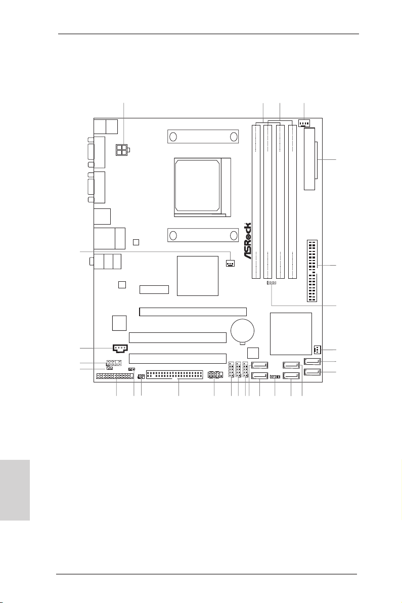
Motherboard Layout
ATXP WR1
AMD
760G
Chipset
PCI 1
LAN
AUDIO
CODEC
1
CLRCMOS1
CPU_FAN1
HD_AUDIO 1
1
RoH S
16Mb
BIOS
AMD
SB710
Chipse t
USB4_5
1
PCIE 2
96 0GC -G S FX
Top:
LINE I N
Center :
FRONT
Bottom :
MIC IN
PS2
Mouse
PS2
Keyb oard
USB 2. 0
T: USB0
B: USB 1
Top:
RJ-45
USB 2.0
T:U SB2
B: USB3
FS B80 0
DDR II_1 ( 64 bit , 240 -pin m odul e)
DDR 3_A1 ( 64 bit , 240 -pin m odul e)
COM 1
ATX12V1
AM 2/ AM 3/ AM3+
SATAII_1 (PORT0)
CI1
1
XF ast RAM
X
Fas t U SB
XF ast LAN
PCIE 1
PCI 2
FS B80 0
DDR II_2 ( 64 bit , 240 -pin m odul e)
DDR 3_B1 ( 64 bit , 240 -pin m odul e)
VGA 1
IDE1
FLOPP Y1
CD1
SPDIF_O UT1
1
1
LPT1
IR1
1
HDLED RESE T
PLED PWRBTN
PANEL1
1
USB6_7
1
USB8_9
1
PWR_FAN1
CHA_FAN1
SATAII_2 (PORT1)
SATAII_3 (PORT2)
SATAII_4 (PORT3)
SATAII_5 (PORT4)
SATAII_6 (PORT5)
SPEAKER1
1
7
8
9
10
14
16
1112
13
17
19
20
2122
23 18
15
25
2
3
4
6
5
1
27
24
26
English
Supe r
1 ATX 12V Power Connector (ATX12V1) 14 SATA2 Connector (SATAII_1 (PORT 0))
2 2 x 240-pin DDR2 DIMM Slots 15 SATA2 Connector (SATAII_2 (PORT 1))
(Dual Channel: DDRII_1, DDRII_2) 16 USB 2.0 Header (USB8_9)
3 2 x 240-pin DDR3 DIMM Slots 17 USB 2.0 Header (USB6_7)
(Dual Channel: DDR3_A1, DDR3_B1) 18 USB 2.0 Header (USB4_5)
4 CPU Fan Connector (CPU_FAN1) 19 System Panel Header (PANEL1)
5 ATX Power Connector (ATXPWR1) 20 Floppy Connector (FLOPPY1)
6 Primary IDE Connector (IDE1) 21 Infrared Module Header (IR1)
7 Clear CMOS Jumper (CLRCMOS1) 22 Chassis Intrusion Header (CI1)
8 Chassis Fan Connector (CHA_FAN1) 23 Print Port Header (LPT1)
9 SATA2 Connector (SATAII_6 (PORT 5)) 24 SPDIF Out Connector (SPDIF_OUT1)
10 SATA2 Connector (SATAII_5 (PORT 4)) 25 Front Panel Audio Header (HD_AUDIO1)
11 SATA2 Connector (SATAII_4 (PORT 3)) 26 Internal Audio Connector (CD1)
12 SATA2 Connector (SATAII_3 (PORT 2)) 27 Power Fan Connector (PWR_FAN1)
13 Chassis Speaker Header (SPEAKER1)
2
I/O
ASRock 960GC-GS FX Motherboard
BAT TERY
CMO S
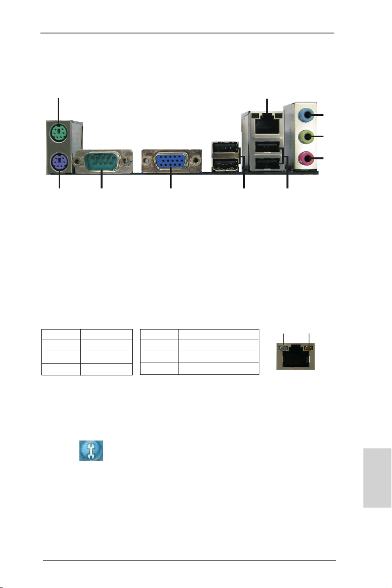
I/O Panel
1
10
1 PS/2 Mouse Port (Green) 6 USB 2.0 Ports (USB01)
* 2 LAN RJ-45 Port 7 USB 2.0 Ports (USB23)
3 Line In (Light Blue) 8 D-Sub Port
** 4 Front Speaker (Lime) 9 COM Port
5 Microphone (Pink) 10 PS/2 Keyboard Port (Purple)
* There are two LED next to the LAN port. Please refer to the table below for the LAN port LED
indications.
Activity/Link LED SPEED LED
Status Description Status Description
LAN Port LED Indications
89
2
7
6
ACT/LINK
LED
SPEED
LED
Off No Link Off 10Mbps connection
Blinking Data Activity Orange 100Mbps connection
On Link Green 1Gbps connection
LAN Port
3
4
5
** To enable Multi-Streaming function, you need to connect a front panel audio cable to the front
panel audio header. Please refer to below steps for the software setting of Multi-Streaming.
For Windows® XP:
After restarting your computer, you will nd “Mixer” tool on your system. Please select “Mixer
ToolBox” , click “Enable playback multi-streaming”, and click “ok”. Choose “2CH” or
“4CH” and then you are allowed to select “Realtek HDA Primary output” to use Rear Speaker
and Front Speaker, or select “Realtek HDA Audio 2nd output” to use front panel audio. Then
reboot your system.
For Windows® 8 / 7 / VistaTM:
After restarting your computer, please double-click “Realtek HD Audio Manager” on the
system tray. Set “Speaker Conguration” to “Quadraphonic” or “Stereo”. Click “Device
advanced settings”, choose “Make front and rear output devices playbacks two different audio
streams simultaneously”, and click “ok”. Then reboot your system.
ASRock 960GC-GS FX Motherboard
English
3
1. Introduction
Thank you for purchasing ASRock 960GC-GS FX motherboard, a reliable motherboard produced under ASRock’s consistently stringent quality control. It delivers
excellent performance with robust design conforming to ASRock’s commitment to
quality and endurance.
This Quick Installation Guide contains introduction of the motherboard and step-by-
step installation guide. More detailed information of the motherboard can be found
in the user manual presented in the Support CD.
Because the motherboard specications and the BIOS software might
be updated, the content of this manual will be subject to change without
notice. In case any modications of this manual occur, the updated version will be available on ASRock website without further notice. You may
nd the latest VGA cards and CPU support lists on ASRock website as
well. ASRock website http://www.asrock.com
If you require technical support related to this motherboard, please visit
our website for specic information about the model you are using.
www.asrock.com/support/index.asp
1.1 Package Contents
ASRock 960GC-GS FX Motherboard (Micro ATX Form Factor)
ASRock 960GC-GS FX Quick Installation Guide
ASRock 960GC-GS FX Support CD
2 x Serial ATA (SATA) Data Cables (Optional)
1 x I/O Panel Shield
English
4
ASRock Reminds You…
To get better performance in Windows® 8 / 8 64-bit / 7 / 7 64-bit / VistaTM
/ VistaTM 64-bit, it is recommended to set the BIOS option in Storage
Conguration to AHCI mode. For the BIOS setup, please refer to the “User
Manual” in our support CD for details.
ASRock 960GC-GS FX Motherboard
1.2 Specications
Platform — Micro ATX Form Factor
CPU — Support for Socket AM3+ processors (see CAUTION 1)
— Support for Socket AM3 processors: AMD PhenomTM II X6 /
X4 / X3 / X2 (except 920 / 940) / Athlon II X4 / X3 / X2 /
Sempron processors
— Support for Socket AM2+ / AM2 processors: AMD PhenomTM
FX / Phenom / Athlon 64 FX / Athlon 64 X2 Dual-Core /
Athlon X2 Dual-Core / Athlon 64 / Sempron processor
— Supports 8-Core CPU
— Supports AMD OverDriveTM with ACC feature (Advanced
Clock Calibration)
— Supports AMD’s Cool ‘n’ QuietTM Technology
— FSB 2600 MHz (5.2 GT/s)
— Supports Untied Overclocking Technology
— Supports Hyper-Transport 3.0 (HT 3.0) Technology
Chipset — Northbridge: AMD 760G
— Southbridge: AMD SB710
Memory — Dual Channel DDR3/DDR2 Memory Technology
— 2 x DDR3 DIMM slots
— Support DDR3 1866(OC)/1600(OC)/1333/1066 non-ECC,
un-buffered memory (see CAUTION 2)
— Max. capacity of system memory: 16GB (see CAUTION 3)
— 2 x DDR2 DIMM slots
— Supports DDR2 1066/800/667/533 non-ECC, un-buffered
memory
— Max. capacity of system memory: 8GB (see CAUTION 3)
Expansion Slot — 1 x PCI Express 2.0 x16 slot (PCIE2 @ x16 mode)
— 1 x PCI Express 2.0 x1 slot
— 2 x PCI slots
Graphics — Integrated AMD Radeon 3000 graphics
— DX10 class iGPU, Pixel Shader 4.0
— Max. shared memory 512MB
— Supports D-Sub with max. resolution up to 2048×1536 @
60Hz
Audio — 5.1 CH HD Audio (Realtek ALC662 Audio Codec)
LAN — PCIE x1 Gigabit LAN 10/100/1000 Mb/s
— Realtek RTL8111G
— Supports Wake-On-LAN
English
ASRock 960GC-GS FX Motherboard
5
English
— Supports LAN Cable Detection
— Supports Energy Efcient Ethernet 802.3az
— Supports PXE
Rear Panel I/O I/O Panel
— 1 x PS/2 Mouse Port
— 1 x PS/2 Keyboard Port
— 1 x Serial Port: COM1
— 1 x D-Sub Port
— 4 x USB 2.0 Ports
— 1 x RJ-45 LAN Port with LED (ACT/LINK LED and SPEED
LED)
— HD Audio Jack: Line in / Front Speaker / Microphone
Storage — 6 x SATA2 3.0 Gb/s connectors, support RAID (RAID 0,
RAID 1, RAID 10 and JBOD), NCQ, AHCI and Hot Plug
Connector — 1 x ATA 133 IDE connector (supports 2 x IDE devices)
— 1 x Floppy connector
— 1 x IR header
— 1 x Print Port header
— 1 x Chassis Intrusion header
— 1 x CPU Fan connector (4-pin)
— 1 x Chassis Fan connector (3-pin)
— 1 x Power Fan connector (3-pin)
— 1 x 24 pin ATX power connector
— 1 x 4 pin 12V power connector
— 1 x CD In header
— 1 x Front panel audio connector
— 1 x SPDIF Out connector
— 3 x USB 2.0 headers (support 6 USB 2.0 ports)
BIOS Feature — 16Mb AMI Legal BIOS
— Supports “Plug and Play”
— ACPI 1.1 Compliance Wake Up Events
— Supports jumperfree
— SMBIOS 2.3.1 Support
— CPU, VCCM, NB Voltage Multi-adjustment
Support CD — Drivers, Utilities, AntiVirus Software (Trial Version),
CyberLink MediaEspresso 6.5 Trial, Google Chrome
Browser and Toolbar
Hardware — CPU/Chassis Temperature Sensing
Monitor — CPU/Chassis/Power Fan Tachometer
— CPU Quiet Fan
— CPU/Chassis/Power Fan Multi-Speed Control
6
ASRock 960GC-GS FX Motherboard

— CASE OPEN detection
— Voltage Monitoring: +12V, +5V, +3.3V, Vcore
OS — Microsoft® Windows® 8 / 8 64-bit / 7 / 7 64-bit / Vista
TM
/
VistaTM 64-bit / XP / XP Media Center / XP 64-bit compliant
Certications — FCC, CE, WHQL
— ErP/EuP Ready (ErP/EuP ready power supply is required)
* For detailed product information, please visit our website: http://www.asrock.com
ASRock 960GC-GS FX Motherboard
English
7

WARNING
Please realize that there is a certain risk involved with overclocking,
including adjusting the setting in the BIOS, applying Untied Overclocking
Technology, or using third-party overclocking tools. Overclocking may
affect your system’s stability, or even cause damage to the components
and devices of your system. It should be done at your own risk and
expense. We are not responsible for possible damage caused by
overclocking.
CAUTION!
1. This motherboard supports CPU up to 95W. Please refer to our
website for CPU support list.
ASRock website: http://www.asrock.com
2. Whether 1866/1600MHz memory speed is supported depends
on the AM3/AM3+ CPU you adopt. If you want to adopt DDR3
1866/1600 memory module on this motherboard, please refer
to the memory support list on our website for the compatible
memory modules.
ASRock website: http://www.asrock.com
3. Due to the operating system limitation, the actual memory size
may be less than 4GB for the reservation for system usage under Windows® 8 / 7 / VistaTM / XP. For Windows® 64-bit OS with
64-bit CPU, there is no such limitation.
English
8
ASRock 960GC-GS FX Motherboard

1.3 Unique Features
ASRock OC Tuner
ASRock OC Tuner is a user-friendly overclocking tool which al-
lows you to surveil your system by hardware monitor function
and overclock your hardware devices to get the best system
performance under Windows® environment. Please visit our
website for the operation procedures of ASRock OC Tuner.
ASRock Intelligent Energy Saver
Featuring an advanced proprietary hardware and software de-
sign, Intelligent Energy Saver is a revolutionary technology that
delivers unparalleled power savings. The voltage regulator can
reduce the number of output phases to improve efciency when
the CPU cores are idle. In other words, it is able to provide exceptional power saving and improve power efficiency without
sacrificing computing performance. To use Intelligent Energy
Saver function, please enable Cool ‘n’ Quiet option in the BIOS
setup in advance. Please visit our website for the operation procedures of Intelligent Energy Saver.
ASRock Instant Boot
ASRock Instant Boot allows you to turn on your PC in just a few
seconds, provides a much more efcient way to save energy,
time, money, and improves system running speed for your system. It leverages the S3 and S4 ACPI features which normally
enable the Sleep/Standby and Hibernation modes in Windows®
to shorten boot up time. By calling S3 and S4 at specic timing
during the shutdown and startup process, Instant Boot allows
you to enter your Windows® desktop in a few seconds.
ASRock Instant Flash
ASRock Instant Flash is a BIOS ash utility embedded in Flash
ROM. This convenient BIOS update tool allows you to update
system BIOS without entering operating systems rst like MS-
DOS or Windows®. With this utility, you can press the <F6> key
during the POST or the <F2> key to enter into the BIOS setup
menu to access ASRock Instant Flash. Just launch this tool and
save the new BIOS le to your USB ash drive, oppy disk or
hard drive, then you can update your BIOS only in a few clicks
without preparing an additional oppy diskette or other
ASRock 960GC-GS FX Motherboard
English
9

complicated flash utility. Please be noted that the USB flash
drive or hard drive must use FAT32/16/12 le system.
ASRock OC DNA
The software name itself – OC DNA literally tells you what it is
capable of. OC DNA, an exclusive utility developed by ASRock,
provides a convenient way for the user to record the OC settings and share with others. It helps you to save your overclocking record under the operating system and simplies the complicated recording process of overclocking settings. With OC DNA,
you can save your OC settings as a prole and share with your
friends! Your friends then can load the OC prole to their own
system to get the same OC settings as yours! Please be noticed
that the OC prole can only be shared and worked on the same
motherboard.
ASRock APP Charger
If you desire a faster, less restricted way of charging your
Apple devices, such as iPhone/iPad/iPod Touch, ASRock has
prepared a wonderful solution for you — ASRock APP Charger.
Simply install the APP Charger driver, it makes your iPhone
charge much quickly from your computer and up to 40% faster
than before. ASRock APP Charger allows you to quickly charge
many Apple devices simultaneously and even supports continuous charging when your PC enters into Standby mode (S1),
Suspend to RAM (S3), hibernation mode (S4) or power off (S5).
With APP Charger driver installed, you can easily enjoy the marvelous charging experience.
English
10
ASRock XFast USB
ASRock XFast USB can boost USB storage device perfor-
mance. The performance may depend on the properties of the
device.
ASRock XFast LAN
ASRock XFast LAN provides a faster internet access, which
includes the benefits listed below. LAN Application Prioritiza-
tion: You can congure your application’s priority ideally and/or
add new programs. Lower Latency in Game: After setting online
game’s priority higher, it can lower the latency in games. Trafc
Shaping: You can watch Youtube HD videos and download
ASRock 960GC-GS FX Motherboard

simultaneously. Real-Time Analysis of Your Data: With the sta-
tus window, you can easily recognize which data streams you
are transferring currently.
ASRock XFast RAM
ASRock XFast RAM fully utilizes the memory space that cannot
be used under Windows® OS 32-bit CPU. ASRock XFast RAM
shortens the loading time of previously visited websites, mak-
ing web surng faster than ever. And it also boosts the speed of
Adobe Photoshop 5 times faster. Another advantage of ASRock
XFast RAM is that it reduces the frequency of accessing your
SSDs or HDDs in order to extend their lifespan.
ASRock X-Boost
ASRock’s X-Boost Technology is a smart auto-overclocking
function and is brilliantly designed to unlock the hidden power of
your CPUs. Simply press “X” when turning on the PC, X-Boost
will automatically overclock the relative components to get up to
15.77% performance boost! With the smart X-Boost, overclock-
ing CPU can become a near one-button process.
* The functionality of “Unlock CPU Cores” feature might vary by
different processors.
ASRock 960GC-GS FX Motherboard
English
11
1.4 Pin Header Easy Installation Guide
1
GND
PRES ENCE#
MIC_ RET
MIC2 _L
MIC2 _R
OUT2 _R
J_SE NSE
OUT2 _L
OUT_ RET
1
PLED +
PLED —
PWRB TN#
HDLE D+
HDLE D-
GND
REST #
GND
DUMM Y
1
USB_ PWR
P-
P+
USB_ PWR
P-
P+
GND
GND
DUMM Y
1
+5V
DUMM Y
SPEA KER
DUMM Y
ASRock motherboard is equipped with pin headers with obvious colors which indicate you to recognize the crucial headers more easily. Please refer to below illustra-
tions for the pin denition of onboard headers. If you want to have more information
about the usage of these headers, please refer to “Jumpers Setup“ and “Onboard
Headers and Connectors“ for details.
Front Panel Audio Header
English
12
SPDIF Out Header
ASRock 960GC-GS FX Motherboard
Chassis Speaker Header
System Panel Header
USB 2.0 Header
1.5 Jumpers Setup
The illustration shows how jumpers are
setup. When the jumper cap is placed on
pins, the jumper is “Short”. If no jumper cap
is placed on pins, the jumper is “Open”. The
illustration shows a 3-pin jumper whose
pin1 and pin2 are “Short” when jumper cap
is placed on these 2 pins.
Jumper Setting Description
Clear CMOS Jumper
(CLRCMOS1)
(see p.2, No. 7)
Note: CLRCMOS1 allows you to clear the data in CMOS. To clear and reset the
system parameters to default setup, please turn off the computer and unplug
the power cord from the power supply. After waiting for 15 seconds, use a
jumper cap to short pin2 and pin3 on CLRCMOS1 for 5 seconds. However,
please do not clear the CMOS right after you update the BIOS. If you need
to clear the CMOS when you just nish updating the BIOS, you must boot
up the system rst, and then shut it down before you do the clear-CMOS action. Please be noted that the password, date, time, user default prole, 1394
GUID and MAC address will be cleared only if the CMOS battery is removed.
Clear CMOSDefault
If you clear the CMOS, the case open may be detected. Please adjust
the BIOS option “Clear Status” to clear the record of previous chassis
intrusion status.
ASRock 960GC-GS FX Motherboard
English
13
1.6 Onboard Headers and Connectors
Onboard headers and connectors are NOT jumpers. Do NOT place
jumper caps over these headers and connectors. Placing jumper caps
over the headers and connectors will cause permanent damage of the
motherboard!
Floppy Connector
(33-pin FLOPPY1)
(see p.2 No. 20)
the red-striped side to Pin1
Note: Make sure the red-striped side of the cable is plugged into Pin1 side of the
connector.
Primary IDE connector
(39-pin IDE1, see p.2 No. 6)
connect the blue end
to the motherboard
80-conductor ATA 66/100/133 cable
Note: Please refer to the instruction of your IDE device vendor for the details.
connect the black end
to the IDE devices
English
14
Serial ATA2 Connectors These six Serial ATA2 (SATA2)
(SATAII_1 (PORT 0):
see p.2, No. 14)
(SATAII_2 (PORT 1):
see p.2, No. 15)
(SATAII_3 (PORT 2):
see p.2, No. 12)
(SATAII_4 (PORT 3):
see p.2, No. 11)
(SATAII_5 (PORT 4):
see p.2, No. 10)
(SATAII_6 (PORT 5):
see p.2, No. 9)
connectors support SATA data
cables for internal storage
devices. The current SATA2
interface allows up to 3.0 Gb/s
data transfer rate.
SATAII_2 (PORT 1)
SATAII_1 (PORT 0)
SATAII_4 (PORT 3)
SATAII_3 (PORT 2)
SATAII_6 (PORT 5)
SATAII_5 (PORT 4)
ASRock 960GC-GS FX Motherboard
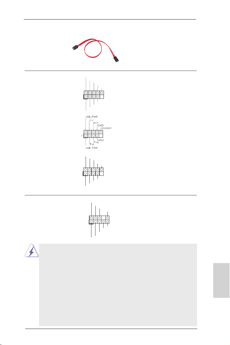
Serial ATA (SATA) Either end of the SATA data
Data Cable cable can be connected to the
(Optional)
SATA2 hard disk or the SATA2
connector on this motherboard.
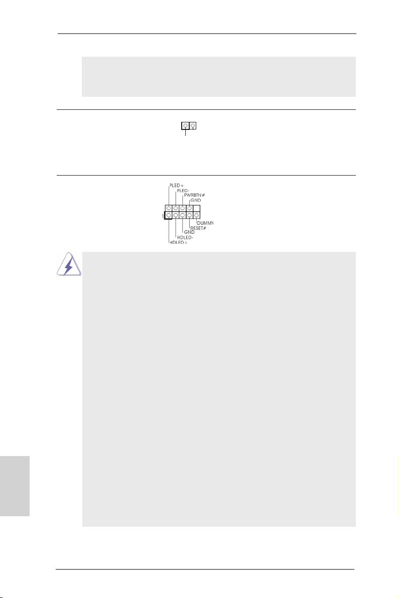
USB 2.0 Headers Besides four default USB 2.0
(9-pin USB4_5)
(see p.2 No. 18)
ports on the I/O panel, there
are three USB 2.0 headers on
this motherboard. Each USB 2.0
header can support two USB
2.0 ports.
(9-pin USB6_7)
(see p.2 No. 17)
(9-pin USB8_9)
(see p.2 No. 16)
Front Panel Audio Header This is an interface for the front
(9-pin HD_AUDIO1)
(see p.2 No. 25)
panel audio cable that allows
convenient connection and
control of audio devices.
1
1
USB _PWR
P-4
P-5
USB _PWR
USB _PWR
P-9
P-8
USB _PWR
GND
1
MIC 2_L
P+4
GND
GND
P+5
P+9
GND
GND
P+8
PRE SENC E#
MIC _RET
OUT 2_R
MIC 2_R
DUM MY
DUM MY
J_S ENSE
OUT _RET
OUT 2_L
1. High Denition Audio supports Jack Sensing, but the panel wire on
the chassis must support HDA to function correctly. Please follow the
instruction in our manual and chassis manual to install your system.
2. If you use AC’97 audio panel, please install it to the front panel audio
header as below:
A. Connect Mic_IN (MIC) to MIC2_L.
B. Connect Audio_R (RIN) to OUT2_R and Audio_L (LIN) to OUT2_L.
C. Connect Ground (GND) to Ground (GND).
D. MIC_RET and OUT_RET are for HD audio panel only. You don’t
need to connect them for AC’97 audio panel.
E. To activate the front mic.
For Windows® XP / XP 64-bit OS:
Select “Mixer”. Select “Recorder”. Then click “FrontMic”.
ASRock 960GC-GS FX Motherboard
English
15
For Windows® 8 / 8 64-bit / 7 / 7 64-bit / VistaTM / VistaTM 64-bit OS:
Go to the «FrontMic» Tab in the Realtek Control panel. Adjust
“Recording Volume”.
English
SPDIF Out Connector Please connect the
(2-pin SPDIF_OUT1)
(see p.2 No. 24)
SPDIF_OUT connector of a
HDMI VGA card to this header
1
GND
SPD I FOUT
with a cable.
System Panel Header This header accommodates
(9-pin PANEL1)
(see p.2 No. 19)
several system front panel
functions.
Connect the power switch, reset switch and system status indicator
on the chassis to this header according to the pin assignments below.
Note the positive and negative pins before connecting the cables.
PWRBTN (Power Switch):
Connect to the power switch on the chassis front panel. You may con-
gure the way to turn off your system using the power switch.
RESET (Reset Switch):
Connect to the reset switch on the chassis front panel. Press the reset
switch to restart the computer if the computer freezes and fails to perform a normal restart.
PLED (System Power LED):
Connect to the power status indicator on the chassis front panel. The
LED is on when the system is operating. The LED keeps blinking
when the sys-tem is in S1 sleep state. The LED is off when the system
is in S3/S4 sleep state or powered off (S5).
HDLED (Hard Drive Activity LED):
Connect to the hard drive activity LED on the chassis front panel. The
LED is on when the hard drive is reading or writing data.
The front panel design may differ by chassis. A front panel module
mainly consists of power switch, reset switch, power LED, hard drive
activity LED, speaker and etc. When connecting your chassis front
panel module to this header, make sure the wire assignments and the
pin assign-ments are matched correctly.
16
ASRock 960GC-GS FX Motherboard
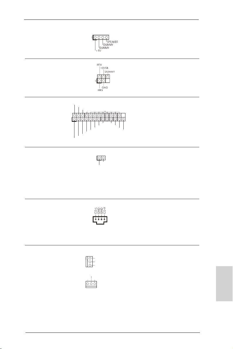
Chassis Speaker Header Please connect the chassis
(4-pin SPEAKER 1)
(see p.2, No. 13)
speaker to this header.
Infrared Module Header This header supports an
(5-pin IR1)
optional wireless transmitting
(see p.2, No. 21)
and receiving infrared module.
Print Port Header This is an interface for print
(25-pin LPT1)
(see p.2 No. 23)
port cable that allows
convenient connection of printer
devices.
1
AFD #
STB #
ERR OR#
PIN I T#
SPD 1
SPD 0
SLI N #
SPD 2
SPD 3
SPD 4
SPD 5
SPD 6
GND
SPD 7
ACK #
BUS Y
PE
SLC T
Chassis Intrusion Header This motherboard supports
(2-pin CI1)
CASE OPEN detection feature
(see p.2 No. 22)
that detects if the chassis cover
1
Sig n al
GND
has been removed. This feature
requires a chassis with chassis
intrusion detection design.
Internal Audio Connectors This connector allows you
(4-pin CD1)
(CD1: see p.2 No. 26)
to receive stereo audio input
from sound sources such as
CD1
a CD-ROM, DVD-ROM, TV
tuner card, or MPEG card.
Chassis and Power Fan Connectors Please connect the fan cable
(3-pin CHA_FAN1)
(see p.2 No. 
ground pin.
(3-pin PWR_FAN1)
(see p.2 No. 27)
to the fan connector and
match the black wire to the
GND
+12 V
GND
+12 V
CHA _FAN_ SPEE D
PWR _FAN _SPE ED
English
ASRock 960GC-GS FX Motherboard
17
Loading…

1
ASRock 960GC-GS FX Motherboard
English
Copyright Notice:
No part of this installation guide may be reproduced, transcribed, transmitted, or trans-
lated in any language, in any form or by any means, except duplication of documentation
by the purchaser for backup purpose, without written consent of ASRock Inc.
Products and corporate names appearing in this guide may or may not be registered
trademarks or copyrights of their respective companies, and are used only for identifica-
tion or explanation and to the owners’ benefit, without intent to infringe.
Disclaimer:
Specifications and information contained in this guide are furnished for informational use
only and subject to change without notice, and should not be constructed as a commit-
ment by ASRock. ASRock assumes no responsibility for any errors or omissions that may
appear in this guide.
With respect to the contents of this guide, ASRock does not provide warranty of any kind,
either expressed or implied, including but not limited to the implied warranties or condi-
tions of merchantability or fitness for a particular purpose. In no event shall ASRock, its
directors, officers, employees, or agents be liable for any indirect, special, incidental, or
consequential damages (including damages for loss of profits, loss of business, loss of
data, interruption of business and the like), even if ASRock has been advised of the pos-
sibility of such damages arising from any defect or error in the guide or product.
This device complies with Part 15 of the FCC Rules. Operation is subject to the following
two conditions:
(1) this device may not cause harmful interference, and
(2) this device must accept any interference received, including interference that
may cause undesired operation.
CALIFORNIA, USA ONLY
The Lithium battery adopted on this motherboard contains Perchlorate, a toxic substance
controlled in Perchlorate Best Management Practices (BMP) regulations passed by the
California Legislature. When you discard the Lithium battery in California, USA, please
follow the related regulations in advance.
“Perchlorate Material-special handling may apply, see
www.dtsc.ca.gov/hazardouswaste/perchlorate”
ASRock Website: http://www.asrock.com
Published June 2013
Copyright©2013 ASRock INC. All rights reserved.
На этой странице вы можете совершенно бесплатно скачать Инструкция по применению ASRock 960GC-GS FX.
У документа PDF Инструкция по применению 55 страниц, а его размер составляет 2.85 Mb.
Читать онлайн Настольные компьютеры ASRock 960GC-GS FX Инструкция по применению
Скачать файл PDF «ASRock 960GC-GS FX Инструкция по применению» (2.85 Mb)
Популярность:
2200 просмотры
Подсчет страниц:
55 страницы
Тип файла:
Размер файла:
2.85 Mb
Прочие инструкции ASRock 960GC-GS FX
Прочие инструкции ASRock Настольные компьютеры
Прочие инструкции ASRock
-
Страница 1
1 960GC-GS FX User Manual V ersion 1.0 Published June 2013 Copyright©2013 ASRock INC. All rights reserved.[…]
-
Страница 2
2 Copyright Notice: No part of this manual may be reproduced, transcribed, transmitted, or translated in any language, in any form or by any means, except duplication of documentation by the purchaser for backup purpose, without written consent of ASRock Inc. Products and corporate names appearing in this manual may or may not be regis- tered trade[…]
-
Страница 3
3 Contents 1. Introduction ………………………………………………………. 5 1.1 Package Contents ………………………………………………… ………… 5 1.2 Specications ………………………………………………………………….. 6 1.3 Unique Features ……………………………………[…]
-
Страница 4
4 3. BIOS SETUP UTILITY …………………………………………. 32 3.1 Introduction …………………………………………………………………….. 32 3.1.1 BIOS Menu Bar ………………………………………………… …… 32 3.1.2 Navigation Keys ……………………………………………………..[…]
-
Страница 5
5 1. Introduction Than k yo u f or p urchas ing AS Rock 96 0GC-G S FX m other board, a reli able mo th- erboard produced under ASRock’s consistently stringent quality control. It delivers excellent performance with robust design conforming to ASRock’s commitm ent to quality and endurance. In this manual, chapter 1 and 2 contain introduction of […]
-
Страница 6
6 1.2 Specications Platform — Micro A TX Form Factor CPU — Support for Socket AM3+ processors (see CAUTION 1 ) — Support for Socket AM3 processors: AMD Phenom TM II X6 / X4 / X3 / X2 (except 920 / 940) / Athlon II X4 / X3 / X2 / Sempron processors — Support for So cket AM2+ / AM2 processors: AMD Phenom TM FX / Phenom / Athlon 64 FX / Athlon 64 X[…]
-
Страница 7
7 — Supports LAN Cable Detection — Supports Energy Efcient Ethernet 802.3az — Supports PXE Rear Panel I/O I/O Panel — 1 x PS/2 Mouse Port — 1 x PS/2 Keyboard Port — 1 x Serial Port: COM1 — 1 x D-Sub Port — 4 x USB 2.0 Ports — 1 x RJ-45 LAN Port with LED (ACT/LINK LED and SPEED LED) — HD Audio Jack: Line in / Front Speaker / Microphone Storage — […]
-
Страница 8
8 CAUTION! 1. This motherboard supports CPU up to 95W . Please refer to our website for CPU support list. ASRock webs ite: http://www .asrock.com 2. Whether 1866/1600MHz memory speed is supported depends on the AM3/AM3+ CPU you adopt. If you want to adopt DDR3 1866/16 00 mem ory mo dule on this motherbo ard, p lease refer to th e m emory s uppor t […]
-
Страница 9
9 1.3 Unique Features ASRock OC T uner ASRock OC T uner is a user-friendly overclocking tool which al- lows you to surveil your s ystem by hardware monitor function and ove rclo ck y our h ardw are de vice s to get the b est s ystem pe rf or ma nc e u nd er W in do ws ® e nv iro nm en t. P le as e v is it ou r website for the operation procedures […]
-
Страница 10
10 c omp lic ate d f lash ut ilit y . Ple ase be n ote d th at t he US B f lash drive or hard drive must use F A T32/16/12 le system. ASRock OC DNA The software name itself – OC DNA literally tells you what it is capable of. OC DNA, an exclusive utility developed by ASRock, provides a c onvenient wa y for the user to recor d the OC set- tings […]
-
Страница 11
1 1 simultaneously . Real-Time Analysis of Y our Data: With the sta- tus window, you can easily recognize which data streams you are transferring currently . ASRock XFast RAM ASRock XFast RAM fully utilizes the memory space that cannot be used under Windows ® OS 32-bit CPU. ASRock XFast RAM shortens th e loading time of pr eviously visited web sit[…]
-
Страница 12
12 1.4 Motherboard Layout 1 A TX 12V Power Connector (A TX12V1) 14 SA T A2 Connector (SA T AII_1 (PORT 0)) 2 2 x 240-pin DDR2 DIMM Slots 15 SA T A2 Connector (SA T AII_2 (PORT 1)) (Dual Channel: DDRII_1, DDRII_2) 16 USB 2.0 Header (USB8_9) 3 2 x 240-pin DDR3 DIMM Slots 17 USB 2.0 Header (USB6_7) (Dual Channel: DDR3_A1, DDR3_B1) 18 USB 2.0 Header (U[…]
-
Страница 13
13 1.5 I/O Panel LAN Port ACT/LINK LED SPEED LED * There are two LED next to the LAN port. Please refer to the table below for the LAN port LED indications. LAN Port LED Indications Activity/Link LED SPEED LED Status Description Status Description Off No Link Of f 10Mbps connection Blinking Data Activity Orange 100Mbps connection On Link Green 1Gbp[…]
-
Страница 14
14 2. Installation This is a Micro A TX form factor motherboard. Before you install the motherboard, study the conguration of your chassis to ensure that the motherboard ts into it. Pre-installation Precautions T ake no te o f t he fo llo wing pre cau tion s b efo re yo u in sta ll mo ther boa rd components or change any motherboard settings.[…]
-
Страница 15
15 STEP 1: Lift Up The Socket Lever STEP 2 / STEP 3: Match The CPU Golden T riangle T o The Socket Corner Small T riangle STEP 4: Push Down And Lock The Socket Lever Lever 90° Up CPU Golden T riangle Socker Corner Small T riangle 2.1 CPU Installation Step 1. Unlock the socket by lifting the lever up to a 90 o angle. Step 2. Position the CPU direct[…]
-
Страница 16
16 1. If you want to install two memory modules, for optimal compatibility and reliability , it is recommended to install them in the slots of the sam e col or . In oth er wo rds, in stall th em in th e set of b lack slo ts (DDR3_A1 and DDR3_B1), or in the set of yellow slots (DDRII_1 and DDRII_2). 2. If o nly o ne me mory mo dule is in stal led i […]
-
Страница 17
17 DDR3_A1 DDR3_B1 (Black Slot) (Black Slot) 2 memory modules SS SS 2 memory modules DS DS DDRII_1 DDRII_2 (Y ellow Slot) (Y ellow Slot) 2 memory modules SS SS 2 memory modules DS DS n ot ch b re ak Installing a DIMM Please make sure to disconnect power supply before adding or removing DIMMs or the system components. Step 1. Unlock a DIMM slot by p[…]
-
Страница 18
18 2.4 Expansion Slots (PCI and PCI Express Slots) There are 2 PCI slots and 2 PCI Express slots on this motherboard. PCI Slots: PCI slots are used to install expansion cards that have the 32-bit PCI interface. PCIE Slots: PCIE1 (PCIE x1 slot) is used for PCI Express x1 lane width graphics cards. PCIE2 (PCIE x16 slot) is used for PCI Express x16 la[…]
-
Страница 19
19 2.5 Multi Monitor Feature This motherboard supports multi monitor feature. With the internal VGA output support and the external add-on PCI Express VGA card, you can easily enjoy the benets of multi monitor feature. Please refer to the following steps to set up a surround display environment: 1. Install the PCI Express VGA cards on PCIE2 slot[…]
-
Страница 20
20 D. Click “Extend my Windows desktop onto this monitor”. E. Right-click the display icon and select “Attached”, if necessary . F . Set the “Screen R esolution ” and “Col or Qualit y” as app ropriate for the second monitor . Click “Apply” or “OK” to apply these new values. G. Repeat steps C through E for the diaplay icon id[…]
-
Страница 21
21 2.6 Jumpers Setup T h e i l l u s t r a t io n s h o w s h o w j u m p e r s a r e setup. When the jumper cap is placed on pins, the jumper is “Short”. If no jumper cap is placed on pins, the jumper is “Open”. The i l lu s t r at i o n s h ow s a 3 — pi n j u m p er w ho s e pin1 and pin2 are “Short” when jumper cap is placed on thes[…]
-
Страница 22
22 2.7 Onboard Headers and Connectors Onboar d headers and con nectors a re NOT jum pers. Do NOT place jumper caps over these headers and connectors. Placing jumper caps over the headers and connectors will cause permanent damage of the motherboard! Serial A T A2 Connectors These six Serial A T A2 (SA T A2) (SA T AII_1 (PORT 0): connectors support […]
-
Страница 23
23 Serial A T A (SA T A) Ei th er en d of t he S A T A da ta Data Cable cable can be connected to the (Optional) SA T A2 hard disk or the SA T A2 connector on this motherboard. 1 U S B _P WR P-8 G ND D UM MY U S B _P WR P + 8 G ND P-9 P + 9 USB 2.0 Headers Besides four default USB 2.0 (9-pin USB4_5) ports on the I/O panel, there (see p.12 No. 18) a[…]
-
Страница 24
24 System Panel Header This header accommodates (9-pin P ANEL1) several system front panel (see p.12 No. 19) functions. Connect the po wer switch , reset switch an d system statu s indicato r on the chassis to this header according to the pin assignments below . Note the positive and negative pins before connecting the cables. PWRBTN (Power Switch)[…]
-
Страница 25
25 Infrared Module Header This header supports an (5-pin IR1) optional wireless transmitting (see p.12, No. 21) and receiving infrared module. Print Port Header This is an interface for print (25-pin LPT1) port cable that allows (see p.12 No. 23) convenient connection of printer devices. 1 AF D# ER RO R# PI NI T# GN D SL IN # ST B# SP D0 SP D1 SP D[…]
-
Страница 26
26 CPU Fan Connector Please connect the CPU fan (4-pin CPU_F AN1) cable to the connector and (see p.12 No. 4) match the black wire to the ground pin. Though this motherboard provides 4-Pin CPU fan (Quiet Fan) support, the 3-Pin CPU fan still can work successfully even without the fan speed control function. If you plan to connect the 3-Pin CPU fan […]
-
Страница 27
27 2.8 Serial A T A2 (SA T A2) Hard Disks Installation This motherboard adopts AMD SB710 chipset that supports Serial A T A2 (SA T A2) hard disks and RAID (RAID 0, RAID 1, RAID 10 and JBOD) functions. Y ou may in — stall SA T A2 hard disks on this motherboard for internal storage devices. This section will guide you to install the SA T A2 hard disk[…]
-
Страница 28
28 2.10 Driver Installation Guide T o install the drivers to your system, please insert the support CD to your optical drive rst. Then, the drivers compatible to your system can be auto-detected and listed on the support CD driver page. Please follow the order from up to bottom side to install those required drivers. Therefore, the drivers you i[…]
-
Страница 29
29 2.1 1.2 Installing Windows ® 8 / 8 64-bit / 7 / 7 64-bit / Vista TM / Vista TM 64-bit With RAID Functions If you want to install Windows ® 8 / 8 64-bit / 7 / 7 64-bit / Vista TM / V ista TM 64-bit on a RAID disk composed of 2 or more SA T A / SA T A2 HDDs with RAID functions, please follow below steps. STEP 1: Set up BIOS. A. Enter BIOS SETUP […]
-
Страница 30
30 Using SA T A / SA T A2 HDDs without NCQ and Hot Plug functions (IDE mode) STEP 1: Set up BIOS. A. Enter BIOS SETUP UTILITY Advanced screen Storage Conguration. B. Set the “SA T A Operation Mode” option to [IDE]. STEP 2: Install Windows ® XP / XP 64-bit OS on your system. 2.12 Installing Windows ® 8 / 8 64-bit / 7 / 7 64-bit / Vista TM /[…]
-
Страница 31
31 2.12.2 Installing Windows ® 8 / 8 64-bit / 7 / 7 64-bit / Vista TM / Vista TM 64-bit Without RAID Functions If you want to install Windows ® 8 / 8 64-bit / 7 / 7 64-bit / Vista TM / Vista TM 64-bit on your SA T A / SA T A2 HDDs without RAID functions, please follow below steps. 2.13 Untied Overclocking T echnology This mot herboard suppor ts U[…]
-
Страница 32
32 3. BIOS SETUP UTILITY 3.1 Introduction This section explains how to use the BIOS SETUP UTILITY to congure your sys — tem. The SPI Memory on the motherboard stores the BIOS SETUP UTILITY . Y ou may run the BIOS SETUP UTILITY when you start up the computer . Please press <F2> or <Del> du ring t he Pow er-On-Self-T est (POST) to ente[…]
-
Страница 33
33 3.1.2 Navigation Keys Please check the following table for the function description of each navigation key . Navigation Key(s) Function Description / Moves cursor left or right to select Screens / Moves cursor up or down to select items + / — T o change option for the selected items <Enter> T o bring up the selected screen <F1> T o d[…]
-
Страница 34
34 3.3 OC T weaker Screen In the OC T weaker screen, you can set up overclocking features. CPU Conguration Overclock Mode Use this to select Overclock Mode. The default value is [Auto]. Congura — tion options: [Auto], [CPU, PCIE, Sync.], [CPU, PCIE, Async.] and [Opti- mized]. CPU Frequency (MHz) Use this option to adjust CPU frequency . PCIE […]
-
Страница 35
35 North Bridge Maximum Frequency It will display North Bridge Maximum Frequency for reference. Processor Maximum V oltage It will display Processor Maximum Voltage for reference. Multiplier/V oltage Change This item is set to [Auto] by default. If it is set to [Manual], you may adjust the value of Processor Frequency and Processor V oltage. Howeve[…]
-
Страница 36
36 B IO S S E TU P U TI L IT Y M em or y T im in g Se l ec t S cr ee n Se l ec t I te m +- C ha ng e O pt io n F1 Ge ne ra l H el p F9 Lo ad De f au lt s F1 0 Sa ve a nd E xi t ES C Ex i t v 02 .5 4 ( C ) C op y ri gh t 1 98 5- 20 0 3, A me r i c an M eg a tr en ds , I nc . O C Twe ak e r Se l ec t S cr ee n Se l ec t I te m +- C ha ng e O pt io n […]
-
Страница 37
37 TRC Use this to adjust TRC values. The default value is [Auto]. TWR Use this to adjust TWR values. The default value is [Auto]. TRFC Use this to adjust TRFC values. The default value is [Auto]. TRRD Use this to adjust TRRD values. The default value is [Auto]. TWTR Use this to adjust TWTR values. The default value is [Auto]. TRTP Use this to adju[…]
-
Страница 38
38 Instant Flash Instant Flash is a BIOS ash utility embedded in Flash ROM. This con — ve ni en t B IO S u pd ate to ol a ll ow s y ou t o u pd at e s ys te m B IO S w it hou t entering operating systems rst like MS-DOS or Windows ® . Just launch this tool and save the new BIOS le to your USB ash drive, oppy disk or hard drive, then[…]
-
Страница 39
39 Cool ‘n’ Quiet Use this item to enable or disable AMD’s Cool ‘n’ Quiet TM technology . The default value is [Enabled]. Conguration options: [Enabled] and [Disabled]. If you install Window s ® 8 / 7 / Vista TM and w ant t o enab le th is fu nction, please set this item to [Enabled]. Please note that enabling this function may reduce[…]
-
Страница 40
40 3.4.2 Chipset Conguration Onboard HD Audio Select [Auto], [Enabled] or [Disabled] for the onboard HD Audio feature. If you select [Auto], the onboard HD Audio will be disabled when PCI Sound Card is plugged. Front Panel Select [Auto] or [Disabled] for the onboard HD Audio Front Panel. Onboard Lan This allows you to enable or disable the onboa[…]
-
Страница 41
41 B IO S S E TU P U T I L IT Y A CP I S e tt in gs Se l ec t a ut o- d et ec t o r di s ab le t he S TR fe a tu re. Se l ec t S cr ee n Se l ec t I te m +- C ha ng e O pt io n F1 Ge ne ra l H el p F9 Lo ad D ef au lt s F1 0 Sa ve a nd E xi t ES C E xi t v 02 .5 4 ( C ) C op y ri gh t 1 98 5- 20 0 3, A me r ic an M e ga tr en ds , I nc . A dv an ce[…]
-
Страница 42
42 ACPI HPET table Use this item to enable or disable ACPI HPET T able. The default value is [Enabled]. Please set this option to [Enabled] if you plan to use this moth- erboard to submit Windows ® certication.[…]
-
Страница 43
43 3.4.4 Storage Conguration Onboard SA T A Controller Use this item to enable or disable the “Onboard SA T A Controller” feature. SA T A Operation Mode Use this item to adjust Onboard SA T A Operation Mode. The default value of this option is [AHCI]. Conguration options: [AHCI], [IDE] and [RAID]. If you set this item to RAID mode, it is […]
-
Страница 44
44 B IO S S E TU P U TI L IT Y A dv an ce d P CI / P nP S e tt in gs Val ue i n u ni ts o f P CI cl o ck s f or P C I d ev ic e la t en cy t im er re gi st er. Se l ec t S cr ee n Se l ec t I te m +- C ha ng e O pt io n F1 Ge ne ra l H el p F9 Lo ad De f au lt s F1 0 Sa ve a nd E xi t ES C Ex i t v 02 .5 4 ( C ) C op y ri gh t 1 98 5- 20 0 3, A me […]
-
Страница 45
45 B IO S S E TU P U TI L IT Y F lo pp y C on fi gu r at io n Se l ec t t he t yp e o f fl o pp y d ri ve co n ne ct ed t o t he sy s te m. Se l ec t S cr ee n Se l ec t I te m +- C ha ng e O pt io n F1 Ge ne ra l H el p F9 Lo ad D e f au lt s F1 0 Sa ve a nd E xi t ES C E x i t v 02 .5 4 ( C ) C op y ri gh t 1 98 5- 20 0 3, A me r ic an M e ga tr […]
-
Страница 46
46 3.4.7 Super IO Conguration OnBoard Floppy Controller Use this item to enable or disable oppy drive controller . Serial Port Address Use this item to set the address for the onboard serial port. Conguration options: [3F8 / IRQ4] and [3E8 / IRQ4]. Infrared Port Use this item to enable or disable the onboard infrared port. Infrared Port Ad[…]
-
Страница 47
47 3.4.8 USB Conguration USB 2.0 Controller Use this item to enable or disable the use of USB 2.0 controller . USB 2.0 Support Use this option to enable or disable support for USB 2.0 devices. The de- fault value is [Enabled]. Legacy USB Support Use this option to select legacy support for USB devices. There are four co n fi g ur at io n o pt io[…]
-
Страница 48
48 CPU Fan Setting This allows you to set the CPU fan speed. Con guration options: [Full On] and [Automatic Mode]. The default is value [Full On]. Chassis Fan 1 Setting This allows you t o set the chassis fan 1 speed. Con guration options: [Full On], [Manual Mode] and [Automatic Mode]. The default is value [Full On]. Case Open Feature This al[…]
-
Страница 49
49 3.6 Boot Screen In this section, it will display the available devices on your system for you to cong — ure the boot settings and the boot priority . B IO S S E TU P U T I L IT Y M ai n O C Tw ea ke r A d va nc ed H /W M on i to r S ec ur it y Ex i t B oo t S e tt in gs Co n fi gu re S et ti ng s du r in g S ys t e m B oo t. Se l ec t S cr ee[…]
-
Страница 50
50 3.7 Security Screen In this section, you may set or change the supervisor/user password for the system. For the user password, you may also clear it. B IO S S E TU P U TI L IT Y M ai n O C Tw e a ke r A dv a nc ed H /W M on it o r Bo o t E xi t In s ta ll o r C h an ge t he pa s sw or d. Se l ec t S cr ee n Se l ec t I te m En t er Ch an ge F1 G[…]
-
Страница 51
51 3.8 Exit Screen Save Changes and Exit When you select this option, it will pop-out the following message, “Save conguration changes and exit setup?” Select [OK] to save the changes and exit the BIOS SETUP UTILITY . Discard Changes and Exit When y ou select this op tion, it will pop- out the f ollowing message, “Discard changes and exit […]
-
Страница 52
52 4. Software Support 4.1 Install Operating System Th is m oth erbo ard s uppo rts v ario us Mi cros oft ® Wi ndow s ® op erat ing s yste ms: 8 / 8 64-bit / 7 / 7 64-bit / Vista TM / Vista TM 64-bit / XP / XP Media Center / XP 64-bit. Because motherb oard settings and hardwar e options vary , use the setup pr ocedures in this chapter for general[…]
Найди любой мануал:
Например: Sony VGN-FW460J/T
Вы можете бесплатно скачать Руководство по эксплуатации для ASRock 960GC-GS FX.
Также вы сможете прочесть онлайн этот документ без скачивания.
Скачать Руководство по эксплуатации для ASRock 960GC-GS FX
Тип файла
PDF
Размер
1.68 Mb
Кол-во страниц
52
Просмотров
2917
Читать онлайн Руководство по эксплуатации для ASRock 960GC-GS FX (Страница 1)

Другие Настольные компьютеры ASRock 960GC-GS FX
Топ ASRock Настольные компьютеры
Ранее вы смотрели
Эта страница полезна для вас? Поделитесь ссылкой: