
Manuals.eu
- Manuals.eu
- ASRock
- Computers & Peripherals
- Mainboards
- B560M Pro4
- User Manual
×
1
2
3
4
5
6
7
8
9
10
11
12
13
14
15
16
17
18
19
20
21
22
23
24
25
26
27
28
29
30
31
32
33
34
35
36
37
38
39
40
41
42
43
44
45
46
47
48
49
50
51
52
53
54
55
56
57
58
59
60
61
62
63
64
65
66
67
68
69
70
71
72
73
74
75
76
77
78
79
80
81
82
83
84
85
86
87
88
89
90
91
92
93
94
95
96
97
98
⟨
⟩
Copyright © Manuals.eu
Agreement
Privacy Policy
Contact us
Version 1.0
Published January 2021
Copyright©2021 ASRock INC. All rights reserved.
Copyright Notice:
No part of this documentation may be reproduced, transcribed, transmitted, or
translated in any language, in any form or by any means, except duplication of
documentation by the purchaser for backup purpose, without written consent of
ASRock Inc.
Products and corporate names appearing in this documentation may or may not
be registered trademarks or copyrights of their respective companies, and are used
only for identication or explanation and to the owners’ benet, without intent to
infringe.
Disclaimer:
Specications and information contained in this documentation are furnished for
informational use only and subject to change without notice, and should not be
constructed as a commitment by ASRock. ASRock assumes no responsibility for
any errors or omissions that may appear in this documentation.
With respect to the contents of this documentation, ASRock does not provide
warranty of any kind, either expressed or implied, including but not limited to
the implied warranties or conditions of merchantability or tness for a particular
purpose.
In no event shall ASRock, its directors, ocers, employees, or agents be liable for
any indirect, special, incidental, or consequential damages (including damages for
loss of prots, loss of business, loss of data, interruption of business and the like),
even if ASRock has been advised of the possibility of such damages arising from any
defect or error in the documentation or product.
is device complies with Part 15 of the FCC Rules. Operation is subject to the following
two conditions:
(1) this device may not cause harmful interference, and
(2) this device must accept any interference received, including interference that
may cause undesired operation.
CALIFORNIA, USA ONLY
e Lithium battery adopted on this motherboard contains Perchlorate, a toxic substance
controlled in Perchlorate Best Management Practices (BMP) regulations passed by the
California Legislature. When you discard the Lithium battery in California, USA, please
follow the related regulations in advance.
“Perchlorate Material-special handling may apply, see www.dtsc.ca.gov/hazardouswaste/
perchlorate”
ASRock Website: http://www.asrock.com


Version 1.0
Published January 2021
Copyright©2021 ASRock INC. All rights reserved.
Copyright Notice:
No part of this documentation may be reproduced, transcribed, transmitted, or
translated in any language, in any form or by any means, except duplication of
documentation by the purchaser for backup purpose, without written consent of
ASRock Inc.
Products and corporate names appearing in this documentation may or may not
be registered trademarks or copyrights of their respective companies, and are used
only for identication or explanation and to the owners’ benet, without intent to
infringe.
Disclaimer:
Specications and information contained in this documentation are furnished for
informational use only and subject to change without notice, and should not be
constructed as a commitment by ASRock. ASRock assumes no responsibility for
any errors or omissions that may appear in this documentation.
With respect to the contents of this documentation, ASRock does not provide
warranty of any kind, either expressed or implied, including but not limited to
the implied warranties or conditions of merchantability or tness for a particular
purpose.
In no event shall ASRock, its directors, ocers, employees, or agents be liable for
any indirect, special, incidental, or consequential damages (including damages for
loss of prots, loss of business, loss of data, interruption of business and the like),
even if ASRock has been advised of the possibility of such damages arising from any
defect or error in the documentation or product.
is device complies with Part 15 of the FCC Rules. Operation is subject to the following
two conditions:
(1) this device may not cause harmful interference, and
(2) this device must accept any interference received, including interference that
may cause undesired operation.
CALIFORNIA, USA ONLY
e Lithium battery adopted on this motherboard contains Perchlorate, a toxic substance
controlled in Perchlorate Best Management Practices (BMP) regulations passed by the
California Legislature. When you discard the Lithium battery in California, USA, please
follow the related regulations in advance.
“Perchlorate Material-special handling may apply, see ww w.dtsc.ca.gov/hazardouswaste/
perchlorate”
ASRock Website: http://www.asrock.com

AUSTRALIA ONLY
Our goods come with guarantees that cannot be excluded under the Australian Consumer
Law. You are entitled to a replacement or refund for a major failure and compensation for
any other reasonably foreseeable loss or damage caused by our goods. You are also entitled
to have the goods repaired or replaced if the goods fail to be of acceptable quality and the
failure does not amount to a major failure. If you require assistance please call ASRock Tel
: +886-2-28965588 ext.123 (Standard International call charges apply)
e terms HDMI® and HDMI High-Denition Multimedia Interface, and the HDMI
logo are trademarks or registered trademarks of HDMI Licensing LLC in the United
States and other countries.
INTEL END USER SOFTWARE LICENSE AGREEMENT
IMPORTANT — READ BEFORE COPYING, INSTALLING OR USING.
LICENSE. Licensee has a license under Intel’s copyrights to reproduce Intel’s Soware
only in its unmodied and binar y form, (with the accompanying documentation, the
“Soware”) for Licensee’s personal use only, and not commercial use, in connection with
Intel-based products for which the Soware has been provided, subject to the following
conditions:
(a) Licensee may not disclose, distribute or transfer any part of the Soware, and You agree
to prevent unauthorized copying of the Soware.
(b) Licensee may not reverse engineer, decompile, or disassemble the Soware.
(c) Licensee may not sublicense the Soware.
(d) e Soware may contain the soware and other intellectual property of third party
suppliers, some of which may be identied in, and licensed in accordance with, an enclosed
license.txt le or other text or le.
(e) Intel has no obligation to provide any support, technical assistance or updates for the
Soware.
OWNERSHIP OF SOFTWARE AND COPYRIGHTS. Title to all copies of the Soware
remains with Intel or its licensors or suppliers. e Soware is copyrighted and protected
by the laws of the United States and other countries, and international treaty provisions.
Licensee may not remove any copyright notices from the Soware. Except as other wise
expressly provided above, Intel grants no express or implied right under Intel patents,
copyrights, trademarks, or other intellectual property rights. Transfer of the license terminates Licensee’s right to use the Soware.
DISCLAIMER OF WARRANTY. e Soware is provided “AS IS” without warranty of
any kind, EITHER EXPRESS OR IMPLIED, INCLUDING WITHOUT LIMITATION,
WARRANTIES OF MERCHANTABILITY OR FITNESS FOR ANY PARTICULAR PURPOSE.
LIMITATION OF LIABILITY. NEITHER INTEL NOR ITS LICENSORS OR SUPPLIERS
WILL BE LIABLE FOR ANY LOSS OF PROFITS, LOSS OF USE, INTERRUPTION OF
BUSINESS, OR INDIRECT, SPECIAL, INCIDENTAL, OR CONSEQUENTIAL DAMAG-

ES OF ANY KIND WHETHER UNDER THIS AGREEMENT OR OTHERWISE, EVEN
IF INTEL HAS BEEN ADVISED OF THE POSSIBILITY OF SUCH DAMAGES.
LICENSE TO USE COMMENTS AND SUGGESTIONS. is Agreement does NOT
obligate Licensee to provide Intel with comments or suggestions regarding the Soware.
However, if Licensee provides Intel with comments or suggestions for the modication,
correction, improvement or enhancement of (a) the Soware or (b) Intel products or
processes that work with the Soware, Licensee grants to Intel a non-exclusive, worldwide,
perpetual, irrevocable, transferable, royalty-free license, with the right to sublicense, under
Licensee’s intellectual property rights, to incorporate or otherwise utilize those comments
and suggestions.
TERMINATION OF THIS LICENSE. Intel or the sublicensor may terminate this license
at any time if Licensee is in breach of any of its terms or conditions. Upon termination,
Licensee will immediately destroy or return to Intel all copies of the Soware.
THIRD PARTY BENEFICIARY. Intel is an intended beneciary of the End User License
Agreement and has the right to enforce all of its terms.
U.S. GOVERNMENT RESTRICTED RIGHTS. e Soware is a commercial item (as
dened in 48 C.F.R. 2.101) consisting of commercial computer soware and commercial
computer soware documentation (as those terms are used in 48 C.F.R. 12.212), consistent
with 48 C.F.R. 12.212 and 48 C.F.R 227.7202-1 through 227.7202-4. You will not provide
the Soware to the U.S. Government. Contractor or Manufacturer is Intel Corporation,
2200 Mission College Blvd., Santa Clara, CA 95054.
EXPORT LAWS. Licensee agrees that neither Licensee nor Licensee’s subsidiaries will
export/re-export the Soware, directly or indirectly, to any country for which the U.S.
Department of Commerce or any other agency or department of the U.S. Government
or the foreign government from where it is shipping requires an export license, or other
governmental approval, without rst obtaining any such required license or approval. In
the event the Soware is exported from the U.S.A. or re-exported from a foreign destination by Licensee, Licensee will ensure that the distribution and export/re-export or import
of the Soware complies with all laws, regulations, orders, or other restrictions of the U.S.
Export Administration Regulations and the appropriate foreign government.
APPLICABLE LAWS. is Agreement and any dispute arising out of or relating to it will
be governed by the laws of the U.S.A. and Delaware, without regard to conict of laws
principles. e Parties to this Agreement exclude the application of the United Nations
Convention on Contracts for the International Sale of Goods (1980). e state and federal
courts sitting in Delaware, U.S.A. will have exclusive jurisdiction over any dispute arising
out of or relating to this Agreement. e Parties consent to persona l jurisdiction and venue
in those courts. A Party that obtains a judgment against the other Party in the courts identied in this section may enforce that judgment in any court that has jurisdiction over the
Parties.
Licensee’s specic rights may vary from country to country.

Contents
Chapter 1 Introduction 1
1.1 Package Contents 1
1.2 Specications 2
1.3 Motherboard Layout 7
1.4 I/O Panel 9
Chapter 2 Installation 10
2.1 Installing the CPU 11
2.2 Installing the CPU Fan and Heatsink 14
2.3 Installing Memory Modules (DIMM) 15
2.4 Expansion Slots (PCI Express Slots) 17
2.5 Jumpers Setup 18
2.6 Onboard Headers and Connectors 19
2.7 Post Status Checker 25
2.8 M.2 WiFi/BT Module and Intel® CNVi (Integrated WiFi/BT)
Installation Guide 26
2.9 M.2_SSD (NGFF) Module Installation Guide (M2_1) 28
2.10 M.2_SSD (NGFF) Module Installation Guide (M2_2) 31
2.11 M.2_SSD (NGFF) Module Installation Guide (M2_3) 34
Chapter 3 Software and Utilities Operation 37
3.1 Installing Drivers 37
3.2 ASRock Motherboard Utility (A-Tuning) 38
3.3 ASRock Live Update & APP Shop 41

3.3.1 UI Overview 41
3.3.2 Apps 42
3.3.3 BIOS & Drivers 45
3.3.4 Setting 46
3.4 Nahimic Audio 47
3.5 ASRock Polychrome SYNC 48
Chapter 4 UEFI SETUP UTILITY 51
4.1 Introduction 51
4.2 EZ Mode 52
4.3 Advanced Mode 53
4.3.1 UEFI Menu Bar 53
4.3.2 Navigation Keys 54
4.4 Main Screen 55
4.5 OC Tweaker Screen 56
4.6 Advanced Screen 68
4.6.1 CPU Conguration 69
4.6.2 Chipset Conguration 71
4.6.3 Storage Conguration 74
4.6.4 Super IO Conguration 75
4.6.5 ACPI Conguration 76
4.6.6 USB Conguration 77
4.6.7 Trusted Computing 78
4.7 Tools 79
4.8 Hardware Health Event Monitoring Screen 81

4.9 Security Screen 85
4.10 Boot Screen 86
4.11 Exit Screen 89

Chapter 1 Introduction
ank you for purchasing ASRock B560 Pro4 motherboard, a reliable motherboard
produced under ASRock ’s consistently stringent quality control. It delivers excellent
performance with robust design conforming to ASRock ’s commitment to quality
and endurance.
In this documentation, Chapter 1 and 2 contains the introduction of the
motherboard and step-by-step installation guides. Chapter 3 contains the operation
guide of the soware and utilities. Chapter 4 contains the conguration guide of
the BIOS setup.
Becau se the motherboard specications and the BIOS soware might be updated, the
content of this documentation will be subject to change without notice. In case any
modications of this documentation occur, the updated version will be available on
ASRock’s website w ithout f urther notice. If you require technical support relate d to
this motherboard, please vi sit our website for s pecic information about the model
you are using. You may nd the l atest VGA cards and CPU suppor t list on ASRock’s
website a s well. ASRock website http://www.asrock.com.
1.1 Package Contents
ASRock B560 Pro4 Motherboard (ATX Form Factor)
•
ASRock B560 Pro4 Quick Installation Guide
•
ASRock B560 Pro4 Support CD
•
2 x Serial ATA (SATA) Data Cables (Optional)
•
4 x Screws for M.2 Sockets (Option al)
•
1 x Stando for M.2 Socket (Optional)
•
1 x I/O Panel Shield
•
B560 Pro4
English
1

1.2 Specications
Platform
CPU
Chipset
Memory
* 11th Gen Intel® CoreTM (i9/i7/i5) support DDR4 up to 2933;
CoreTM (i3), Pentium® and Celeron® support DDR4 up to 2666.
* 10th Gen Intel® CoreTM (i9/i7) support DDR4 up to 2933; CoreTM
(i5/i3), Pentium® and Celeron® support DDR4 up to 2666.
* Please refer to Memory Support List on ASRock’s website for
more information. (http://www.asrock.com/)
ATX Form Factor
•
Solid Capacitor design
•
Suppor ts 10th Gen Intel® CoreTM Processors and 11th Gen
•
Intel® CoreTM Processors (LGA1200)
Digi Power design
•
8 Power Phase design
•
Supports Intel® Turbo Boost Max 3.0 Technology
•
Intel® B560
•
Dual Channel DDR4 Memory Technology
•
4 x DDR4 DIMM Slots
•
11th Gen Intel® CoreTM Processors support DDR4 non-ECC,
•
un-buered memory up to 4800+(OC)*
10th Gen Intel® CoreTM Processors support DDR4 non-ECC,
•
un-buered memory up to 4600+(OC)*
Supports ECC UDIMM memory modules (operate in non-
•
ECC mode)
Max. capacity of system memory: 128GB
•
Supports Intel® Extreme Memory Prole (XMP) 2.0
•
English
2

B560 Pro4
Expansion
Slot
Graphics
11th Gen Intel® CoreTM Processors
2 x PCI Express x16 Slots (PCIE1/PCIE3: single at Gen4x16
•
(PCIE1); dual at Gen4x16 (PCIE1) / Gen3x2 (PCIE3))*
10th Gen Intel® CoreTM Processors
2 x PCI Express x16 Slots (PCIE1/PCIE3: single at Gen3x16
•
(PCIE1); dual at Gen3x16 (PCIE1) / Gen3x2 (PCIE3))*
* Supports NVMe SSD as boot disks
2 x PCI Express 3.0 x1 Slots
•
1 x M.2 Socket (Key E), supports ty pe 2230 WiFi/BT module
•
and Intel® CNVi (Integrated WiFi/BT)
* Intel® UHD Graphics Built-in Visuals and the VGA outputs can
be supported only with processors which are GPU integrated.
11th Gen Intel® CoreTM Processors support Intel® Xe Graphics
•
Architecture (Gen 12). 10th Gen Intel® CoreTM Processors
support Gen 9 Graphics
Graphics, Media & Compute: Microso DirectX 12, OpenGL
•
4.5, Intel® Built In Visuals, Intel® Quick Sync Video, Hybrid /
Switchable Graphics, OpenCL 2.1
Display & Content Security: Rec. 2020 (Wide Color Gamut),
•
Microso PlayReady 3.0, UHD/HDR Blu-ray Disc
Dual graphics output: support HDMI and DisplayPort 1.4
•
ports by independent display controllers
Supports HDMI 2.0 with ma x. resolution up to 4K x 2K
•
(4096×2160) @ 60Hz
Supports DisplayPort 1.4 with max. resolution up to 4K x 2K
•
(4096×2304) @ 60Hz
Supports Auto Lip Sync, Deep Color (12bpc), xvYCC and
•
HBR (High Bit Rate Audio) with HDMI 2.0 Port
(Compliant HDMI monitor is required)
Supports HDCP 2.3 with HDMI 2.0 and DisplayPort 1.4
•
Ports
Supports 4K Ultra HD (UHD) playback with HDMI 2.0 and
•
DisplayPort 1.4 Ports
* 11th Gen Intel® CoreTM Processors support HDMI 2.0. 10th Gen
Intel® CoreTM Processors support HDMI 1.4.
Audio
7.1 CH HD Audio (Realtek ALC897 Audio Codec)
•
Supports Surge Protection
•
Nahimic Audio
•
English
3

LAN
Rear Panel
I/O
Storage
Gigabit LAN 10/100/10 00 Mb/s
•
Giga PHY Intel® I219V
•
Supports Wake-On-LAN
•
Supports Lightning/ESD Protection
•
Supports Energy Ecient Ethernet 802.3az
•
Supports PXE
•
3 x Antenna Mounting Points
•
1 x PS/2 Mouse/Keyboard Port
•
1 x HDMI Port
•
1 x DisplayPort 1.4
•
4 x USB 3.2 Gen1 Ports (Supports ESD Protection)
•
2 x USB 2.0 Ports (Supports ESD Protection)
•
1 x RJ-45 LAN Port with LED (ACT/LINK LED and SPEED
•
LED)
HD Audio Jacks: Line in / Front Speaker / Microphone
•
6 x SATA3 6.0 Gb/s Connectors, support Intel Rapid Storage
•
Technology 18, NCQ, AHCI and Hot Plug*
* If M2_3 is occupied by a SATA-type M.2 device, SATA3_1 will
be disabled.
1 x Hyper M.2 Socket (M2_1), supports M Key ty pe
•
2242/2260/2280 M.2 PCI Express module up to Gen4x4
(64 Gb/s) (Only supported with 11th Gen Intel® CoreTM
Processors)**
1 x Ultra M.2 Socket (M2_2), supports M Key type
•
2242/2260/2280 M.2 PCI Express module up to Gen3 x4 (32
Gb/s)**
1 x M.2 Socket (M2_3), supports M Key ty pe 2280/22110 M.2
•
SATA3 6.0 Gb/s module and M.2 PCI Express module up to
Gen3 x2 (16 Gb/s)**
** Supports Intel® OptaneTM Tech nolo gy (M 2_ 2)
** Supports NVMe SSD as boot disks
** Supports ASRock U.2 Kit
English
4

Connector
1 x COM Port Header
•
1 x SPI TPM Header
•
1 x Chassis Intrusion and Speaker Header
•
2 x RGB LED Headers
•
* Support in total up to 12V/3A, 36W LED Strip
2 x Addressable LED Headers
•
* Support in total up to 5V/3A, 15W LED Strip
1 x CPU Fan Connector (4-pin)
•
* e CPU Fan Connector supports the CPU fan of ma ximum
1A (12W) fan power.
1 x CPU/Water Pump Fan Connector (4-pin) (Smart Fan
•
Speed Control)
* e CPU/Water Pump Fan supports the water cooler fan of
maximum 2A (24W) fan power.
5 x Chassis/Water Pump Fan Connectors (4-pin) (Smart Fan
•
Speed Control)
* e Chassis/Water Pump Fan supports the water cooler fan of
maximum 2A (24W) fan power.
* CPU_FAN2/WP, CHA_FAN1/WP, CHA_FAN2/WP, CHA_
FAN3/WP, CHA_FAN4/WP and CHA_FAN5/WP can auto
detect if 3-pin or 4-pin fan is in use.
1 x 24 pin ATX Power Connector
•
1 x 8 pin 12V Power Connector (Hi-Density Power Connec-
•
tor)
1 x Front Panel Audio Connector
•
1 x USB 2.0 Header (Supports 2 USB 2.0 ports) (Supports
•
ESD Protection)
2 x USB 3.2 Gen1 Headers (Support 4 USB 3.2 Gen1 ports)
•
(ASMedia ASM1074 hub) (Supports ESD Protection)
1 x Front Panel Type C USB 3.2 Gen1 Header (Supports ESD
•
Protection)
B560 Pro4
BIOS
Feature
AMI UEFI Legal BIOS with multilingual GUI support
•
ACPI 6.0 Compliant wake up events
•
SMBIOS 2.7 Support
•
CPU Core/Cache, GT, DRAM, VPPM, VCCIN AUX, VCCIO,
•
VCCST, VCCSA Voltage Multi-adjustment
English
5
Temperature Sensing: CPU, CPU/Water Pump, Chassis/Wa-
Hardware
Monitor
•
ter Pump Fans
Fan Tachometer: CPU, CPU/Water Pump, Chassis/Water
•
Pump Fans
Quiet Fan (Auto adjust chassis fan speed by CPU tempera-
•
ture): CPU, CPU/Water Pump, Chassis/Water Pump Fans
Fan Multi-Speed Control: CPU, CPU/Water Pump, Chassis/
•
Water Pump Fans
CASE OPEN detection
•
Voltage monitoring: +12V, +5V, +3.3V, CPU Vcore, DRAM,
•
VPPM, VCCIN AUX, VCCSA, VCCPLL, VCCIO
Microso® Windows® 10 64-bit
OS
Certications
* For detailed product information, please visit our website: http://www.asrock .com
Please realize that the re is a certain r isk involved with overclo cking, including
adjusting the setting in the BIOS, applying Untied Overclocking Technol ogy, or using
third-party overclocking tool s. Overclocking may aect your system’s stability, or
even cause dam age to the components and devices of your system. It should be done
at your own risk and expense. We are not responsible for poss ible damage caused by
overclocking.
•
FCC, CE
•
ErP/EuP ready (ErP/EuP ready power supply is required)
•
English
6
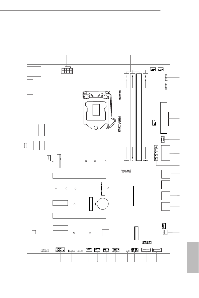
1.3 Motherboard Layout
Intel
B560
DDR 4_A2 (6 4 bit, 28 8-pin m odule )
DDR 4_A1 (6 4 bit, 28 8-pin m odule )
DDR 4_B2 (6 4 bit, 28 8-pin m odule )
DDR 4_B1 (6 4 bit, 28 8-pin m odule )
USB 2. 0
T: USB1
B: USB 2
ATXP WR 1
PCIE1
Top:
RJ-45
USB 3.2 Gen1
T: USB3_1
B: USB3_2
PCIE3
HDLED RESET
PLED PWRBTN
1
1
HD_AUDIO1
10
17
1
PS2
Keybo ard
/Mous e
CMOS
Battery
PCIE2
32
16
9
1
M2_ 1
C 10
C 9
12
Top:
LINE I N
Cent er:
FRON T
Bott om:
MIC IN
1
M2_ WIFI1
M2_WIFI_CT1
M2_ 3
C 23
C 24
HDM I1
PCIE4
T
T
T
T
AUDIO
CODEC
15
26
2
4
CHA_FAN 5/WP
CHA_FAN1/WP
CHA_FAN2/WP
CPU_FAN2/WP
CPU_FAN1
3
5
11
CHA_FAN4/ WP
1
28
1
1
29
1
1
6
SUPER
I/O
USB3_5 _6
USB31_ TC_1
RGB_LE D2
ADDR_L ED2
1
RoHS
C 7
T
ADDR_LED1
RGB_LED1
USB3_4
SATA3_0 SATA3_1
CLRMOS1
PANEL1
ATX12V1
SPI_TPM_J1
SATA3_4
SATA3_5
20
21
24
23
31
D 1
P
7
USB3_7 _8
SATA3_2
SATA3_3
14
13
C 8
T
M2_ 2
C 12
T
C 13
T
C 14
T
C 11
T
1
SPK_CI1
27
CHA_FAN3/WP
COM1
1
30
8
19
22
25
DRAM
BOOT
VGA
CPU
18
USB 3.2 Gen1
T: USB3_3
B: USB3_4
B560 Pro4
English
7

English
No. Description
1 ATX 12V Power Connector (ATX12V1)
2 2 x 288-pin DDR4 DIMM Slots (DDR4_A1, DDR4_B1)
3 2 x 288-pin DDR4 DIMM Slots (DDR4_A2, DDR4_B2)
4 CPU Fan Connector (CPU_FAN1)
5 CPU/Water Pump Fan Connector (CPU_FAN2/WP)
6 Addressable LED Header (ADDR_LED2)
7 RGB LED Header (RGB_LED2)
8 Chassis/Water Pump Fan Connector (CHA_FAN5/WP)
9 ATX Power Connector (ATXPWR1)
10 Front Panel Type C USB 3.2 Gen1 Header (USB31_TC_1)
11 USB 3.2 Gen1 Header (USB3_7_8)
12 USB 3.2 Gen1 Header (USB3_5_6)
13 SATA3 Connector (SATA3_2)
14 SATA3 Connector (SATA3_3)
15 SATA3 Connec tor (SATA3_4)
16 SATA3 Connector (SATA3_5)
17 Chassis/Water Pump Fan Connector (CHA_FAN4/WP)
18 Post Status Checker (PSC)
19 SPI TPM Header (SPI_TPM_J1)
20 SATA3 Connector (SATA3_1)
21 SATA3 Connector (SATA3_0)
22 System Panel Header (PANEL1)
23 Clear CMOS Jumper (CLRMOS1)
24 USB 2.0 Header (USB3_4)
25 Chassis Intrusion and Speaker Header (SPK_CI1)
26 Chassis/Water Pump Fan Connector (CHA_FAN2/WP)
27 Chassis/Water Pump Fan Connector (CHA_FAN3/WP)
28 Addressable LED Header (ADDR_LED1)
29 RGB LED Header (RGB_LED1)
30 COM Port Header (COM1)
31 Front Panel Audio Header (HD_AUDIO1)
32 Chassis/Water Pump Fan Connector (CHA_FAN1/WP)
8
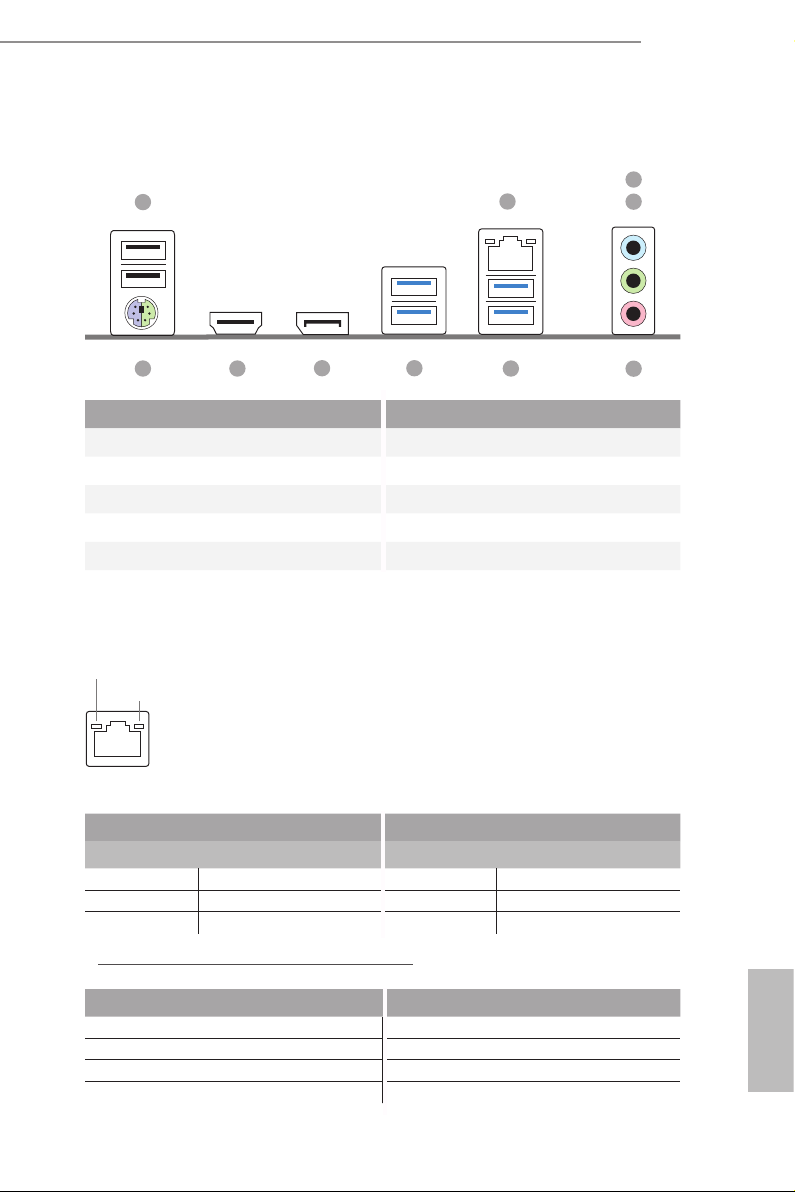
1.4 I/O Panel
1
B560 Pro4
3
2
4
10
9
78
6
No. Description No. Description
1 USB 2.0 Ports (USB1_2) 6 USB 3.2 Gen1 Ports (USB3_1_2)
2 LAN RJ-45 Port* 7 USB 3.2 Gen1 Ports (USB3_3_4)
3 Line In (Light Blue)** 8 DisplayPort 1.4
4 Front Speaker (Lime)** 9 HDMI Port
5 Microphone (Pink)** 10 PS/2 Mouse/Keyboard Port
* ere are two LEDs on each LAN port. Please refer to the table below for the LAN port LED indications .
ACT/LINK LED
SPEED LED
LAN Por t
Activity / Link LED Speed LED
Status Description Status Description
O No Link O 10Mbps connection
Blinking Data Activity Orange 100Mbps connection
On Link Green 1Gbps connection
5
** Function of the Audio Ports in 7.1-channel Conguration:
Port Function
Light Blue (Rear panel) Rear Speaker Out
Lime (Rear panel) Front Speaker Out
Pink (Rear panel) Central /Subwoofer Speaker Out
Lime (Front panel) Side Speaker Out
English
9

Chapter 2 Installation
is is an ATX form factor motherboard. Before you install the motherboard, study
the conguration of your chassis to ensure that the motherboard ts into it.
Pre-installation Precautions
Take note of the following precautions before you install motherboard components
or change any motherboard settings.
Make sure to unplug the power cord before installing or removing the motherboard
•
components. Failure to do so may cause physical injuries and damages to motherboard
components.
In order to avoid damage from static electricity to the motherboard’s components,
•
NEVER place your motherboard directly on a carpet. Also remember to use a grounded
wrist strap or touch a safety grounded object before you handle the components.
Hold components by the edges and do not touch the ICs.
•
Whenever you uninstall any components, place them on a grounded anti-static pad or
•
in the bag that comes with the components.
When placing screws to secure the motherboard to the chassis, please do not over-
•
tighten the screws! Doing so may damage the motherboard.
English
10
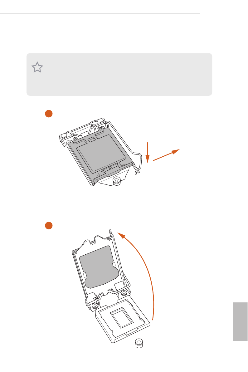
2.1 Installing the CPU
1. Before you insert the 1200-Pin CPU into the socke t, please check if the PnP cap is on the
socket, if the CPU surface is unclean, or if there are any bent pins in the socket. Do not
force to in sert the CPU into the socket if above situation is found. Otherwise, the CPU
will be seriously damaged.
2. Unplug all power c ables before in stalling the CPU.
1
B560 Pro4
A
B
2
English
11
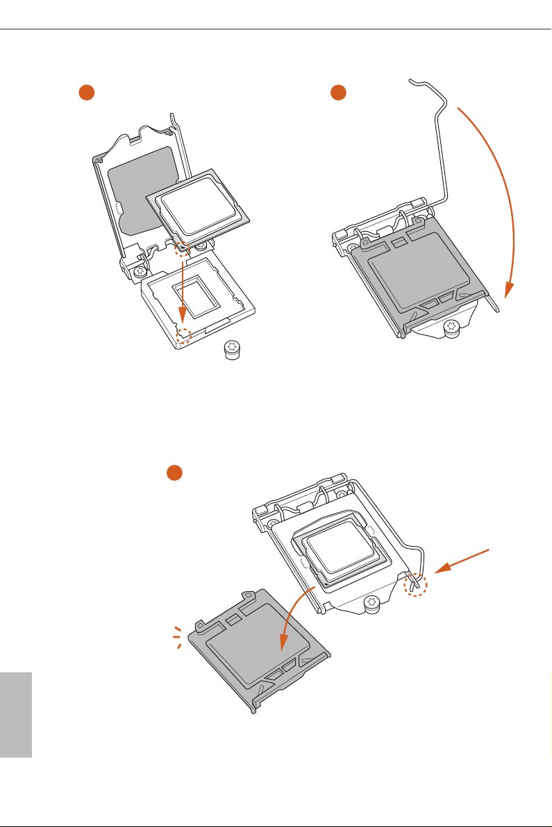
3
5
4
English
12

Please save and replace the cover if the processor i s removed. e cover must be placed if
you wish to return the motherboard for aer service.
B560 Pro4
13
English
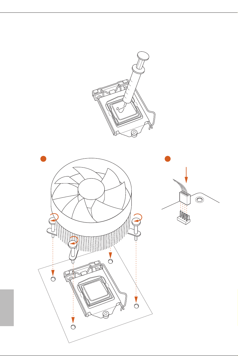
2.2 Installing the CPU Fan and Heatsink
1 2
English
14
CPU_FAN
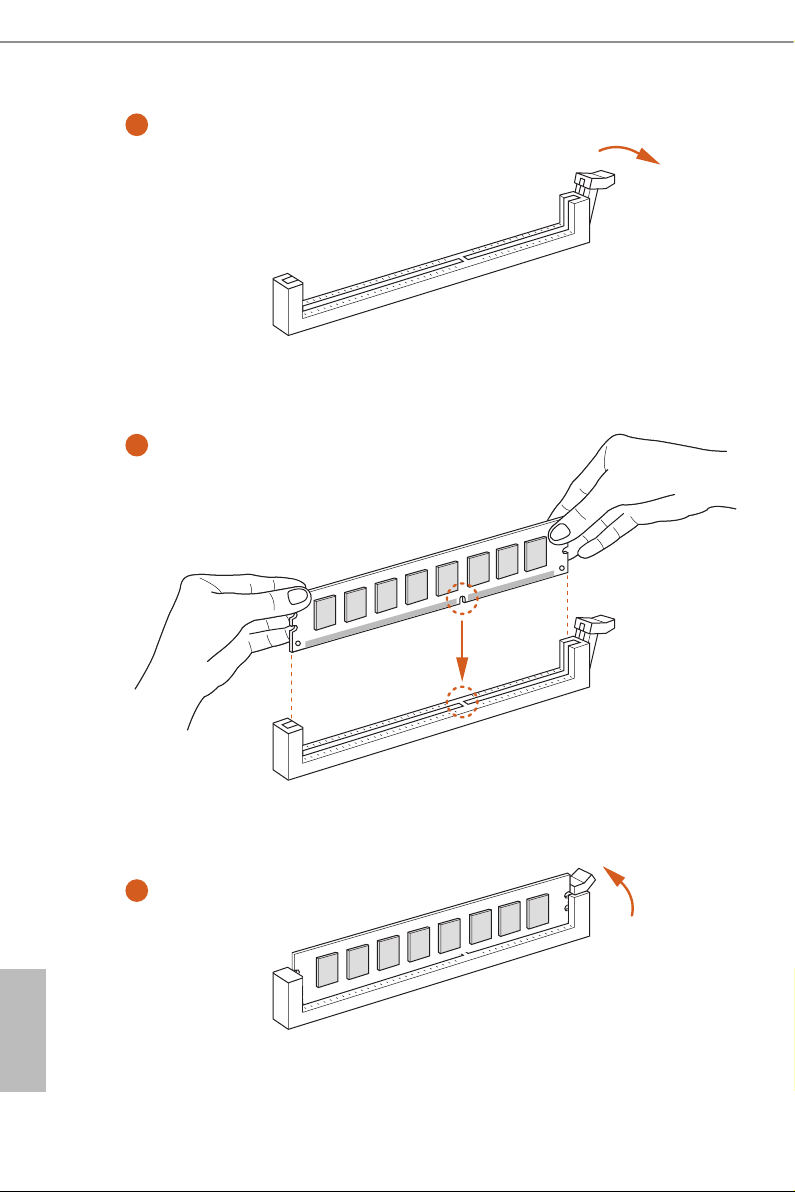
2.3 Installing Memory Modules (DIMM)
is motherboard provides four 288-pin DDR4 (Double Data Rate 4) DIMM slots,
and supports Dual Channel Memory Technology.
1. For dual channe l conguration, you always need to in stall identical (the same
brand, speed , size and chip-type) DDR4 DIMM pairs.
2. It is unable to activate Dual Channel Memor y Te chnology with only one or three
memory module installed.
3. It is not allowed to install a DDR, DDR2 or DDR3 memory module into a DDR4
slot; otherwise, this motherboard and DIMM may be damaged.
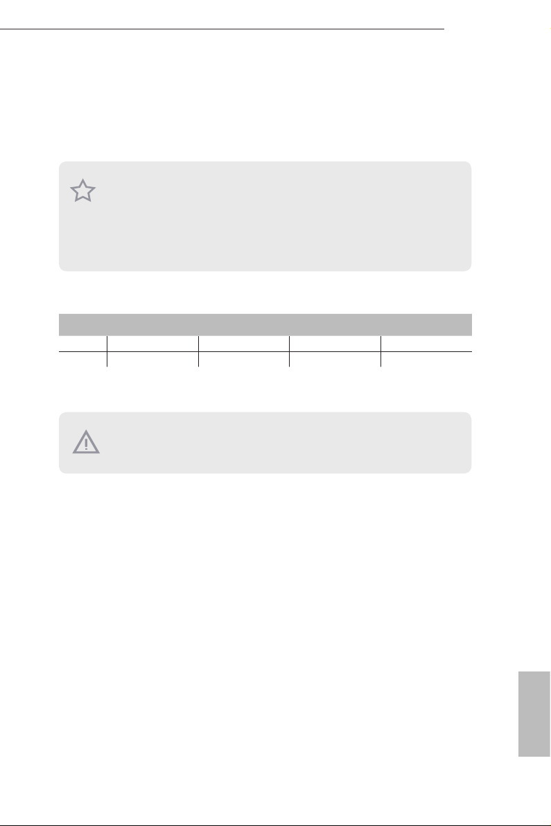
Dual Channel Memory Conguration
Priority DDR4_A1 DDR4_A2 DDR4_B1 DDR4_B2
1 Populated Populated
2 Populated Populated Populated Populated
e DIMM only ts in one correct orientation. It will cause permanent dam age to
the mothe rboard and the DIMM if you force the DIMM into the slot at incor rect
orientation.
B560 Pro4
15
English
1
2
English
16
3
2.4 Expansion Slots (PCI Express Slots)
ere are 4 PCI Express slots on the motherboard.
Before installing an ex pansion card, please make sure that the power supply is
switched o or the power cord is unplugged. Plea se read the documentation of the
expan sion card and mak e necessary hardware settings for the card before you start
the installation.
PCIe slots:
11th Gen Intel® CoreTM Processors:
PCIE1 (PCIe 4.0 x16 slot) is used for PCI Express x16 lane width graphics cards.
PCIE2 (PCIe 3.0 x1 slot) is used for PCI Express x1 lane width cards.
PCIE3 (PCIe 3.0 x16 slot) is used for PCI Express x2 lane width graphics cards.
PCIE4 (PCIe 3.0 x1 slot) is used for PCI Express x1 lane width cards.
10th Gen Intel® CoreTM Processors:
PCIE1 (PCIe 3.0 x16 slot) is used for PCI Express x16 lane width graphics cards.
PCIE2 (PCIe 3.0 x1 slot) is used for PCI Express x1 lane width cards.
PCIE3 (PCIe 3.0 x16 slot) is used for PCI Express x2 lane width graphics cards.
PCIE4 (PCIe 3.0 x1 slot) is used for PCI Express x1 lane width cards.
B560 Pro4
PCIe Slot Congurations
PCIE1 PCIE3
11th Gen Intel® CoreTM Processors Gen4x16 Gen3x 2
10th Gen Intel® CoreTM Processors Gen3x16 Gen3x2
For a better ther mal environment, ple ase connect a ch assi s fan to the motherboard’s
chassis fan connector (CHA_ FAN1/WP, CHA_ FAN2/WP, CHA_FAN3/WP, CHA_
FAN4/WP or CHA_ FAN5/WP) when u sing multiple graphics cards.
English
17
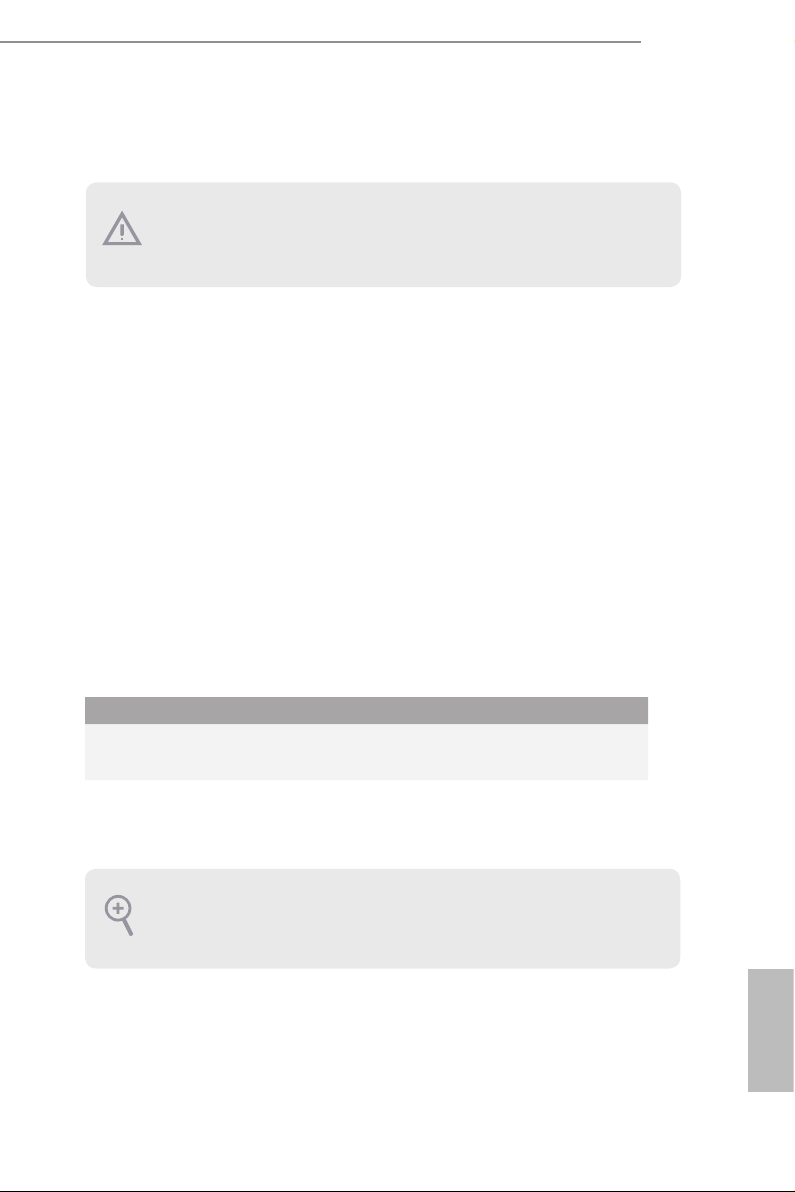
2.5 Jumpers Setup
e illustration shows how jumpers are setup. When the jumper cap is placed on
the pins, the jumper is “Short”. If no jumper cap is placed on the pins, the jumper is
“O pen”.
Clear CMOS Jumper
(CLRMO S1)
(see p.7, No. 23)
CLRMOS1 allows you to clear the data in CMOS. To clear and reset the system
parameters to default setup, please turn o the computer and unplug the power
cord from the power supply. Aer waiting for 15 seconds, use a jumper cap to
short the pins on CLR MOS1 for 5 seconds. However, please do not clear the
CMOS right aer you update the BIOS. If you need to clear the CMOS when you
just nish updating the BIOS, you must boot up the system rst, and then shut it
down before you do the clear-CMOS action. Please be noted that the password,
date, time, and user default prole will be cleared only if the CMOS battery is
removed. Please remember toremove the jumper cap aer clearing the CMOS.
2-pin Jumper
English
18
If you clear the CMOS, the case open may be detec ted. Please adjust the BIOS option “Clear
Status” to clear the record of previous chassis intrusion status.
2.6 Onboard Headers and Connectors
Onboard headers and connectors are NOT jumpers. Do NOT place jumper caps over
these header s and connectors. Placing jumper caps over the headers and connectors
will cause permanent damage to the motherboard.
B560 Pro4
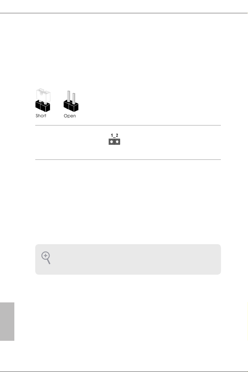
System Panel Header
(9-pi n PANEL1)
(see p.7, No. 22)
PWRBTN (Power Button):
Connec t to the power button on the chassi s front panel. You may congure the way to
turn o your system using the power button.
RESET (Reset Button):
Connec t to the reset button on the chassi s front panel. Press the reset button to
restar t the computer if the computer freezes and fails to perform a nor mal restart.
PLED (Syste m Power LED):
Connec t to the power status indicator on the chassis front panel. e LED i s on when
the system is ope rating. e LED keeps blinking when the system i s in S1/S3 sleep
state. e LED is o when the system is in S4 sleep state or powered o (S5).
HDLED (Ha rd Drive Activity LED):
Connec t to the hard drive ac tivity LED on the chassis front panel. e LED is on
when the hard drive i s reading or writing data.
e front panel de sign may dier by chassis. A front pane l module mainly consists
of power button , reset button, power LED, hard dr ive activity LED, speaker and etc.
When connecting your chassis front panel module to this head er, make sure the wire
assig nments and the pin assig nments are matched correctly.
1
PLED+
PLED-
HDLED-
HDLED+
PWRBTN#
GND
RESET#
GND
GND
Connect the power button,
reset button and system
status indicator on the
chassis to this header
according to the pin
assignments below. Note
the positive and negative
pins before connecting the
cables.
19
English
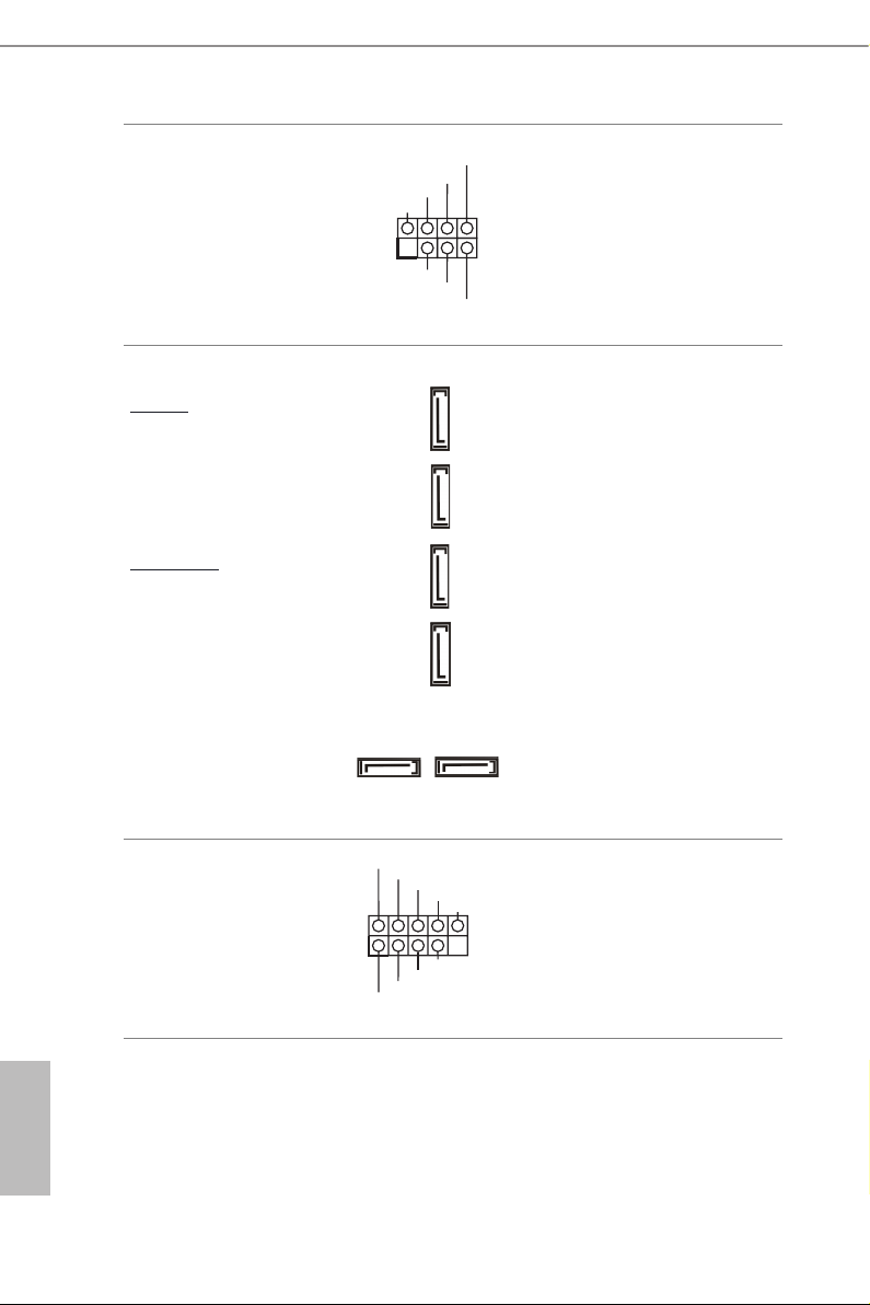
Chassis Intrusion and
Speaker Header
(7-pi n SPK _CI1)
(see p.7, No. 25)
DUMMY
+5V
1
SIGNAL
DUMMY
GND
DUMMY
Please connect the
chassis intrusion and the
chassis speaker to this
header.
Serial ATA3 Connectors
Ver ti c a l:
(SATA3_0:
see p.7, No. 21)
(SATA3_1:
see p.7, No. 20)
Right-A ng le:
(SATA3_ 2:
see p.7, No. 13)
(SATA3_ 3:
see p.7, No. 14)
(SATA3_4:
see p.7, No. 15)
(SATA3_ 5:
see p.7, No. 16)
USB 2.0 Header
(9-pin USB3_4)
(see p.7, No. 24)
SATA3_0
USB_PWR
P-
1
P-
USB_PWR
SATA3_2
SATA3_3
SATA3_4
SATA3_5
P+
P+
SATA3_1
GND
DUMMY
GND
ese six SATA3
connectors support SATA
data cables for internal
storage devices with up to
6.0 Gb/s data transfer rate.
* If M2_3 is occupied by
a SATA-type M.2 device,
SATA3_1 will be disabled.
ere is one USB 2.0 header
on this motherboard.
is USB 2.0 header can
support two ports.
English
20
B560 Pro4
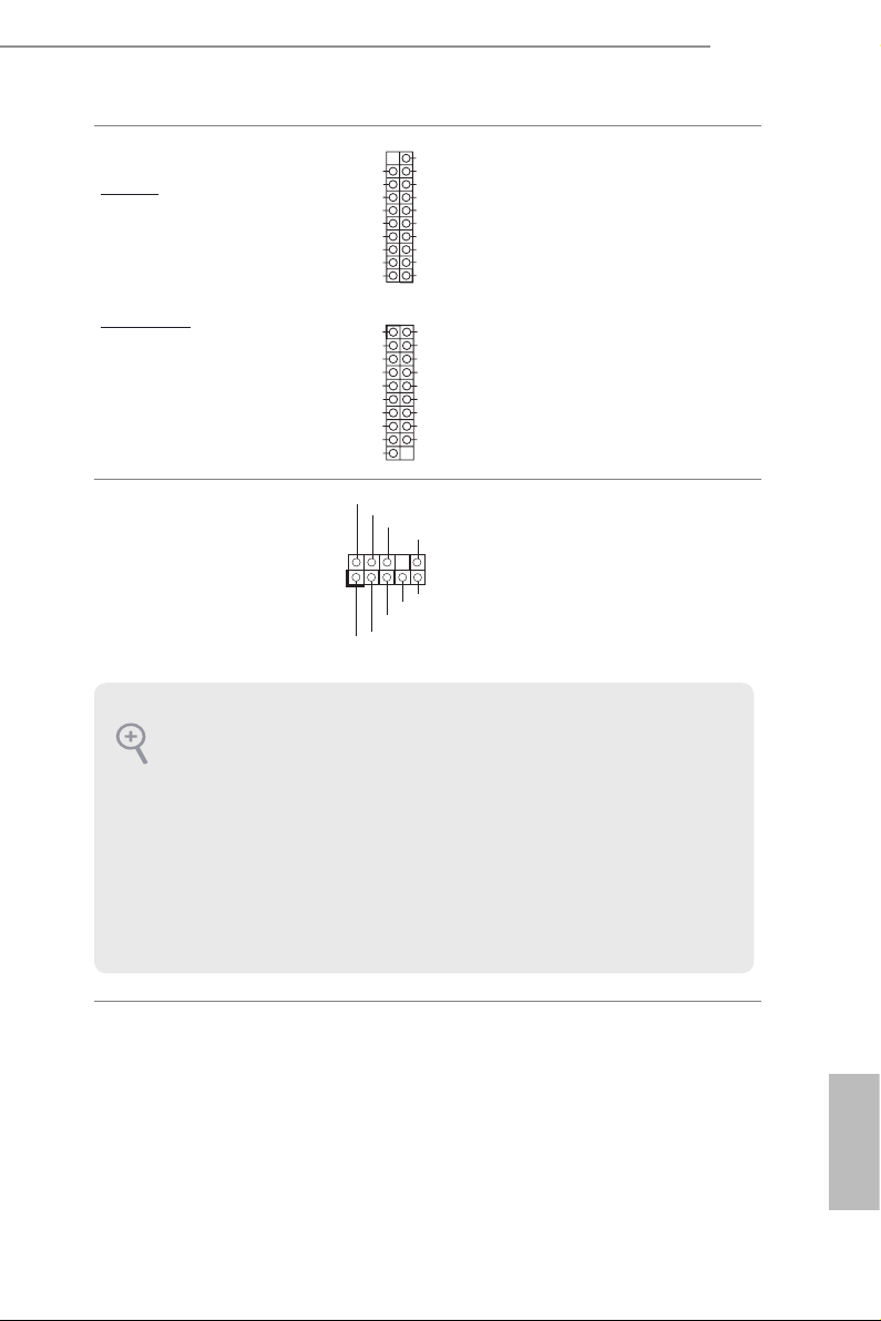
USB 3.2 Gen1 Headers
Ver ti c a l:
(19-pin USB3_5_6)
(see p.7, No. 12)
Right-A ng le:
(19-pin USB3_7_8)
(see p.7, No. 11)
Front Panel Audio Header
(9-pin HD_ AUDIO1)
(see p.7, No. 31)
1. High De nition Audio sup ports Jack Sen sing, but the pan el wire on the chassis
must support HDA to function correctly. Please follow the instructions in our
manual and chassis manual to install your system.
2. If you use an AC’97 audio panel , please install it to the front panel audio header by
the steps below:
A. Connect Mic_IN (MIC) to MIC2_ L.
B. Conne ct Audio_R (RIN) to OUT2_R and Audio_ L (LIN) to OUT2_ L.
C. Connect Ground (GND) to Ground (GND).
D. MIC_ RET and OUT_RET are for the HD audio panel only. You don’t need to
connec t them for the AC’97 audio panel.
E. To activate the front mic, go to the “FrontMic” Tab in the Realtek Control panel
and adjust “Recording Volume”.
Vbus
IntA_PA_SSRX-
IntA_PA_SSRX+
IntA_PA_SSTX-
IntA_PA_SSTX+
IntA_PA_D-
IntA_PA_D+
Dummy
IntA_PB_D+
IntA_PB_D-
IntA_PB_SSTX+
IntA_PB_SSTX-
GND
IntA_PB_SSRX+
IntA_PB_SSRX-
VbusV
GND
1
MIC2_L
GND
GND
GND
PRESENCE#
MIC_RET
OUT2_R
MIC2_R
VbusVbus
IntA_PB_SSRX-
IntA_PB_SSRX+
GND
IntA_PB_SSTX-
IntA_PB_SSTX+
GND
IntA_PB_D-
IntA_PB_D+
Dummy
1
IntA_PA_D+
IntA_PA_D-
GND
IntA_PA_SSTX+
IntA_PA_SSTX-
GND
IntA_PA_SSRX+
IntA_PA_SSRX-
Vbus
OUT_RET
OUT2_L
J_SENSE
ere are two headers on
this motherboard. Each
USB 3.2 Gen1 header can
support two ports.
is header is for
connecting audio devices
to the front audio panel.
English
21
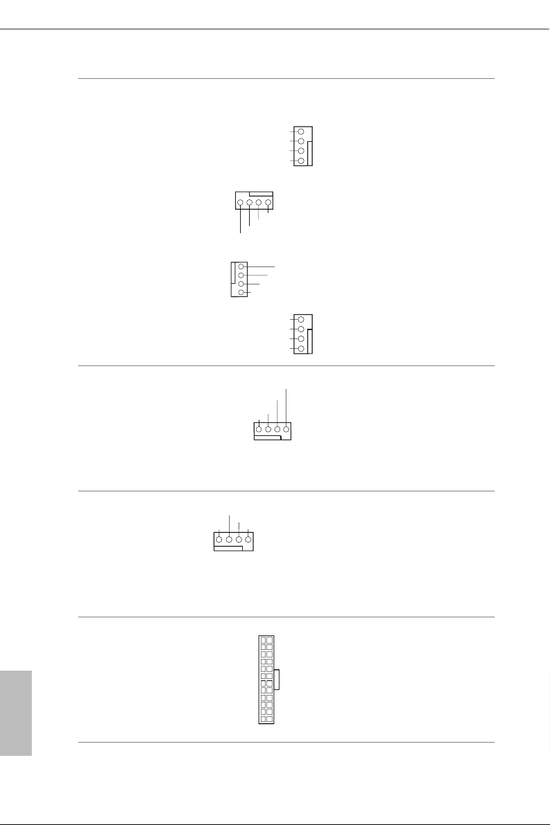
Chassis/Water Pump Fan
Connectors
(4-pin CHA_FAN1/WP)
(see p.7, No. 32)
(4-pin CHA_FAN2/WP)
(see p.7, No. 26)
(4-pin CHA_FAN3/WP)
(see p.7, No. 27)
FAN_SPEED_CONTROL
FAN_SPEED
FAN_VOLTAGE
GND
4 3 2 1
GND
FAN_VOLTAGE
FAN_SPEED
FAN_SPEED_CONTROL
is motherboard provides
ve 4-Pin water cooling
4
chassis fan connectors. If
3
2
you plan to connect a 3-Pin
1
chassis water cooler fan,
please connect it to Pin 1-3.
English
(4-pin CHA_FAN4/WP)
(see p.7, No. 17)
(4-pin CHA_FAN5/WP)
(see p.7, No. 
CPU Fan Connector
(4-pin CPU_FAN1)
(see p.7, No. 4)
CPU/Water Pump Fan
Connector
(4-pin CPU_FAN2/WP)
(see p.7, No. 5)
ATX Power Connector
(24-p i n ATX PWR1)
(see p.7, No. 9)
1
2
3
FAN_SPEED_CONTROL
4
FAN_SPEED_CONTROL
FAN_SPEED
FAN_VOLTAGE
CPU_FAN_SPEED
+12V
GND
1234
FAN_VOLTAGE
CPU_FAN_SPEED
GND
FAN_SPEED_CONTROL
12
1
GND
FAN_VOLTAGE
FAN_SPEED
GND
24
13
4
3
2
1
is motherboard provides
a 4-Pin CPU fan (Quiet
Fan) connector. If you plan
to connect a 3-Pin CPU
fan, please connect it to Pin
1-3.
is motherboard provides
a 4-Pin water cooling CPU
fan connector. If you plan
to connect a 3-Pin CPU
water cooler fan, please
connect it to Pin 1-3.
is motherboard provides
a 24-pin ATX power con-
nector. To use a 20-pin
ATX power supply, please
plug it along Pin 1 and Pin
13.
22
Loading…
| Автор | Сообщение | ||
|---|---|---|---|
|
|||
|
Junior Статус: Не в сети |
Здравствуйте. У меня следующая проблема. Последний раз редактировалось Компьютерщик 13.02.2022 17:47, всего редактировалось 2 раз(а). |
| Реклама | |
|
Партнер |
|
REtaiL_OZ |
|
|
Злостный читер Статус: Не в сети |
Компьютерщик попробуйте так: После перезагрузки попадаете сюда и нажимаете «Поиск и устранение неисправностей» Далее: «Дополнительные параметры» Далее: «Параметры встроенного ПО UEFI» и жмете «Перезагрузить». Ждёте и ничего не нажимаете — система должна сама зайти в BIOS (UEFI) Добавлено спустя 5 минут 9 секунд: |
|
Hro |
|
|
Member Статус: Не в сети |
На странице мат платы сайта асрок скачай программу Asrock Restart to UEFI. |
|
Компьютерщик |
|
|
Junior Статус: Не в сети |
REtaiL_OZ писал(а): Компьютерщик попробуйте так: Это первое что я попробовал, не помогло. Потом начал вынимать ЖД и батарейку. Батарейку вынимал при полностью обесточенном ПК. Загрузка всё равно идёт сразу, или чёрный экран «нет сигнала» при нажатии F2. Добавлено спустя 1 минуту 50 секунд: Hro писал(а): На странице мат платы сайта асрок скачай программу Asrock Restart to UEFI. Вот это ещё не пробовал. Скачаю, проверю. Потом отпишусь. Проверил. Перезагрузка пошла, и чёрный экран. Пришлось отключить кнопкой и запустить снова. Комп запустился как и ранее, сразу в ОС. Последний раз редактировалось Компьютерщик 12.02.2022 17:45, всего редактировалось 1 раз. |
|
REtaiL_OZ |
|
|
Злостный читер Статус: Не в сети |
Компьютерщик а видеокарта умеет в UEFI? или может видеосигнал идёт на через встройку (если есть) |
|
Компьютерщик |
|
|
Junior Статус: Не в сети |
REtaiL_OZ писал(а): Компьютерщик а видеокарта умеет в UEFI? или может видеосигнал идёт на через встройку (если есть) Видео — 1060. При первичной сборке всё было нормально. Проц 11400f без встройки. Дело в том, что я сразу не снял лимиты тдп у проца, и он остался на частоте 2600. А теперь не могу зайти в БИОС, чтоб сменить настройки… Добавлено спустя 17 минут 21 секунду: |
|
Tomick |
|
|
Junior Статус: Не в сети |
Компьютерщик Просто нужно в параметрах отключить быструю загрузку. |
|
Компьютерщик |
|
|
Junior Статус: Не в сети |
Tomick писал(а): Компьютерщик Просто нужно в параметрах отключить быструю загрузку. Такого параметра нету, ОС последней версии. Такой параметр вроде был в предыдущих версиях. #77 |
|
andruhsss |
|
|
Member Статус: Не в сети |
Смени кабель у монитора, есть стоит dp смени на hdmi. Или поробуй в настройках монитора сменить версию dp 1.3/1.4 на 1.2 временно пока биос настраиваешь. Потом нужно применить вот это https://www.nvidia.com › drivers Это массовый глюк сейчас когда народ начал включать secure boot чтобы 11 поставить. Все кривое кривое, как вообще вчя электроника работает хз, глюк на глюке везде. |
|
Ugly-Man |
|
|
Remember Статус: Не в сети |
Компьютерщик Отключи жесткий (или ссд, что там не знаю) и заходи себе в биос на здоровье. Можно в биосе отключить fast start, должно в будущем помочь |
|
Компьютерщик |
|
|
Junior Статус: Не в сети |
andruhsss писал(а): Смени кабель у монитора, есть стоит dp смени на hdmi. Или поробуй в настройках монитора сменить версию dp 1.3/1.4 на 1.2 временно пока биос настраиваешь. Потом нужно применить вот это https://www.nvidia.com › drivers Это массовый глюк сейчас когда народ начал включать secure boot чтобы 11 поставить. Все кривое кривое, как вообще вчя электроника работает хз, глюк на глюке везде. Спасибо тебе большое! Помогло. Монитор подключен по dp. В настройках моника сменил версию dp с 1.4 на 1.2 и заработало! Перезагрузка пошла с заставкой ASrock и кнопками F2, F12, Del и т.д. и получилось зайти в БИОС. |
—
Кто сейчас на конференции |
|
Сейчас этот форум просматривают: нет зарегистрированных пользователей и гости: 3 |
| Вы не можете начинать темы Вы не можете отвечать на сообщения Вы не можете редактировать свои сообщения Вы не можете удалять свои сообщения Вы не можете добавлять вложения |
Asrock B560M Pro4 Hackintosh


Spek :
| Spek | Type |
|---|---|
| CPU | Intel i5-10400F |
| CPU Fan | Noctua NH-L9X65 |
| Motherboard | ASRock B560M Pro4 |
| RAM | GSkill 32 GB |
| VGA | Sapphire RX 5600 XT |
| remot on-off | Ewelink Wifi Smart Switch |
| NVME | WD SN350 |
| WiFi & Bluetooth | Fenvi T919 |
Kexts used:
| Kext | Description | for |
|---|---|---|
| AppleALC.kext | Used for AppleHDA patching, allowing support for the majority of on-board sound controllers. | Audio |
| IntelMausi.kext | Intel’s 82578, 82579, I217, I218 and I219 NICs are officially supported. | Ethernet |
| Lilu.kext | Patch many processes, required for AppleALC, WhateverGreen, VirtualSMC and many other kexts. | |
| SMCProcessor.kext | Used for monitoring CPU temperature, doesn’t work on AMD CPU based systems. | |
| SMCSuperIO.kext | Used for monitoring fan speed, doesn’t work on AMD CPU based systems. | |
| VirtualSMC.kext | Emulates the SMC chip found on real macs, without this macOS will not boot. Alternative is FakeSMC which can have better or worse support, most commonly used on legacy hardware. |
|
| WhateverGreen.kext | Used for graphics patching, DRM fixes, board ID checks, framebuffer fixes, etc; all GPUs benefit from this kext. | |
| NVMeFix | Used for fixing power management and initialization on non-Apple NVMe. | NVMe device |
| SATA-Unsupported | Adds support for a large variety of SATA controllers, mainly relevant for laptops which have issues seeing the SATA drive in macOS. We recommend testing without this first. |
|
| RestrictEvents | Better experience with unsupported processors like AMD, Disable MacPro7,1 memory warnings and provide upgrade to macOS Monterey via Software Updates when available. |
GPU Specific boot-args
| Parameter | Description |
|---|---|
| agdpmod=pikera | Used for disabling board ID checks on Navi GPUs(RX 5000 series), without this you’ll get a black screen. Don’t use if you don’t have Navi (ie. Polaris and Vega cards shouldn’t use this). |
| alcid=»XX» | layout 11, 12, 23, 66, 69, 77 |
Special notes
- USB port mapping is REQUIRED. Guide
XhciPortLimit— NeededDISABLEif you use Big Sur 11.3+.- Please Mapping USB in macOS Catalina before install Big Sur or Newer for best results.USBPorts.kext
AppleXcpmCfgLock— PleaseENABLEif you cannot disableCFG-Lockin BIOS.- Does NOT SUPPORT iGPU in 11th Gen.
- You NEED dGPU (dedicated/discrete GPU (eg. RX 560, 570, 580, 590, RX 5700 XT, etc).
Work & Not
✅
- QE/CI
- CPU Power Management
- Restart, Sleep and Shutdown
- Internal Speaker, Mic, Headphone Audio
- iMessage and FaceTime
- Handoff and Continuity
- Ethernet
- WiFi
- HDMI DP Output
- HDMI DP Audio
- All USB Ports
- Etc
❌
- not yet found
BIOS settings
Enable
- Intel Virtualization Technology (VT-x)
- Multi-processor
- UEFI Boot
- Intel VT-d (or set
DisableIoMapperin theconfig.plisttoFALSE - SATA Mode to AHCI
- XHCI Handoff
- Above 4G Decoding and Clever Access Memory (or set
ResizeAppleGpuBarsto-1)
Disable
- Legacy ROM support
- Secure Boot
- Intel SGX
For Intel 11th gen CPU users
Your iGPU will not be supported in macOS due to Apple’s transistion to Apple Silicon, so you can skip the iGPU configuration step. Using an F-series CPU would be beneficial here.
Also, 11th Gen CPUs are required to change the CPUID by adding these entries under Root > Kernel > Emulate as Apple also doesn’t support them out of the box:
| Key | Type | Value |
|---|---|---|
| Cpuid1Data | Data | <EA060900000000000000000000000000> |
| Cpuid1Mask | Data | <FFFFFFFF000000000000000000000000> |
| DummyPowerManagement | Boolean | 0 |
| MaxKernel | String | |
| MinKernel | String |
Config your iGPU
Not required if you don’t have one. Follow these instructions.
Map your USB
Using USBToolBox is recommended.
Map your ASM107x USB controller (entries 2.0 and 3.0) as type 255 (Internal) as those two stay on all the time.
Note: You must exclude your RGB controller during the mapping process, as it will cause sleep problems and the RGB LEDs will freeze until you fully halt the machine.
Add your own PlatformInfo entries using GenSMBIOS
Use:
iMac20,1if you have an 8-core or lower CPU with an iGPU (ie. i7-10700)iMac20,2if you have a 10-core CPU (ie. i9-10900)iMacPro1,1(orMacPro7,1with the RestrictEvents kext) if you don’t have an iGPU (ie. AMD dGPU with a F-series CPU such as the i5-10400F like me).
helpful app
- Hackintool
- About This Hack
- balenaEtcher
- OCAuxiliaryTools
- Stats
References & thanks
- Apple inc
- dortania.github.io
- olarila.com
- HackintoshLover