
Copyright Notice:Copyright Notice:
Copyright Notice:
Copyright Notice:Copyright Notice:
No part of this installation guide may be reproduced, transcribed, transmitted, or translated in any language, in any form or by any means, except duplication of documentation by the purchaser for backup purpose, without written consent of ASRock Inc.
Products and corporate names appearing in this guide may or may not be registered
trademarks or copyrights of their respective companies, and are used only for identification or explanation and to the owners’ benefit, without intent to infringe.
Disclaimer:Disclaimer:
Disclaimer:
Disclaimer:Disclaimer:
Specifications and information contained in this guide are furnished for informational
use only and subject to change without notice, and should not be constructed as a
commitment by ASRock. ASRock assumes no responsibility for any errors or omissions
that may appear in this guide.
With respect to the contents of this guide, ASRock does not provide warranty of any kind,
either expressed or implied, including but not limited to the implied warranties or
conditions of merchantability or fitness for a particular purpose. In no event shall
ASRock, its directors, officers, employees, or agents be liable for any indirect, special,
incidental, or consequential damages (including damages for loss of profits, loss of
business, loss of data, interruption of business and the like), even if ASRock has been
advised of the possibility of such damages arising from any defect or error in the guide
or product.
This device complies with Part 15 of the FCC Rules. Operation is subject to the
following two conditions:
(1) this device may not cause harmful interference, and
(2) this device must accept any interference received, including interference that
may cause undesired operation.
CALIFORNIA, USA ONLY
The Lithium battery adopted on this motherboard contains Perchlorate, a toxic
substance controlled in Perchlorate Best Management Practices (BMP) regulations
passed by the California Legislature. When you discard the Lithium battery in
California, USA, please follow the related regulations in advance.
“Perchlorate Material-special handling may apply, see
www.dtsc.ca.gov/hazardouswaste/perchlorate”
ASRock Website: http://www.asrock.com
Published January 2010
Copyright©2010 ASRock INC. All rights reserved.
ASRock H55M-LE Motherboard
EnglishEnglish
EnglishEnglish
English
11
1
11
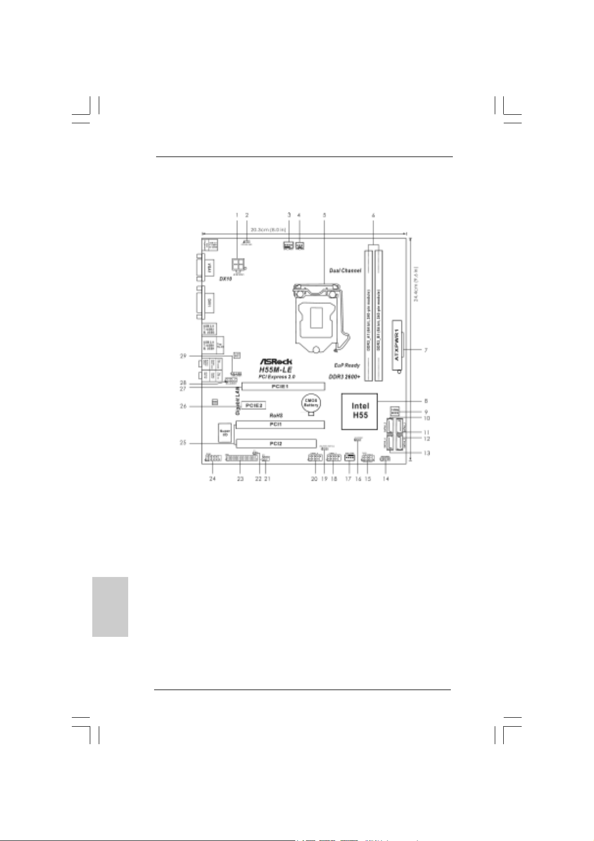
Motherboard LayoutMotherboard Layout
Motherboard Layout
Motherboard LayoutMotherboard Layout
English
EnglishEnglish
EnglishEnglish
22
2
22
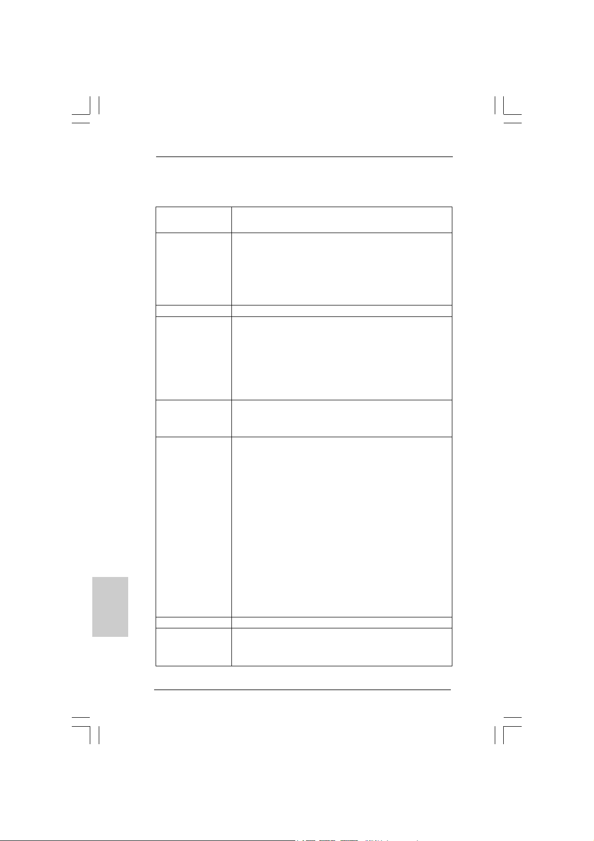
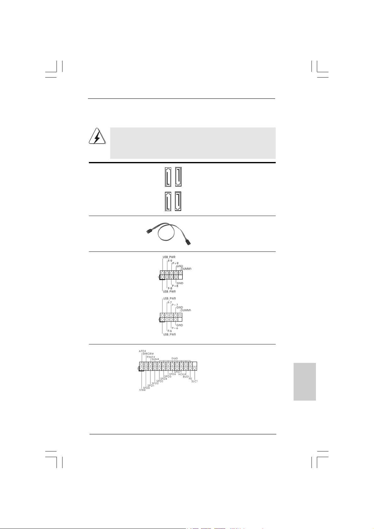
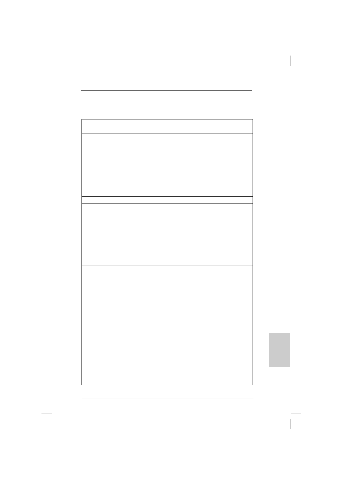
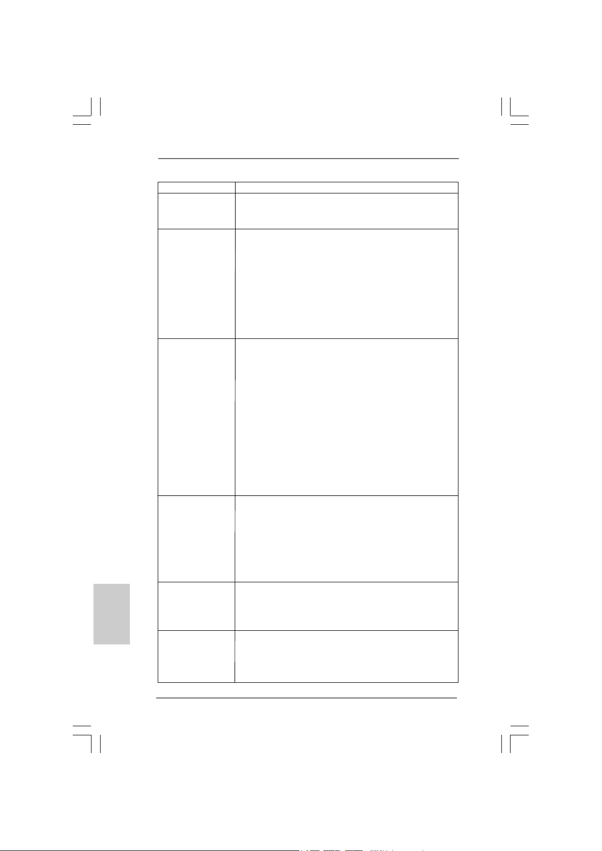
1 A TX 12V Power Connector (A TX12V1) 16 Clear CMOS Jumper (CLRCMOS1)
2 PS2_USB_PWR1 Jumper 17 Chassis Fan Connector (CHA_FAN1)
3 CPU Fan Connector (CPU_FAN1) 18 USB 2.0 Header (USB6_7, Blue)
4 Power Fan Connector (PWR_FAN1) 19 USB_PWR1 (PORT 6-9) Jumper
5 1156-Pin CPU Socket 20 USB 2.0 Header (USB8_9, Blue)
6 2 x 240-pin DDR3 DIMM Slots 21 Infrared Module Header (IR1)
(Dual Channel: DDR3_A1, DDR3_B1, Blue) 22 Chassis Intrusion Header (CI1)
7 ATX Power Connector (ATXPWR1) 23 Print Port Header (LPT1, Purple)
8 Intel H55 Chipset 24 COM Port Header (COM1)
9 16Mb SPI Flash 25 PCI Slots (PCI1-2)
10 Secondary SAT AII Connector (SA T AII_2, Red) 26 PCI Express 2.0 x1 Slot (PCIE2, White)
11 Primary SAT AII Connector (SA T AII_1, Red) 27 PCI Express 2.0 x16 Slot (PCIE1, Blue)
12 Third SAT AII Connector (SA TAII_3, Red) 28 Front Panel Audio Header
13 Fourth SAT AII Connector (SATAII_4, Red) (HD_AUDIO1, Lime)
14 Chassis Speaker Header (SPEAKER 1, Purple) 29 HDMI_SPDIF Header
15 System Panel He ader (P ANEL1, Ora nge) (HDMI_SPDIF1, Yellow)
ASRock H55M-LE Motherboard
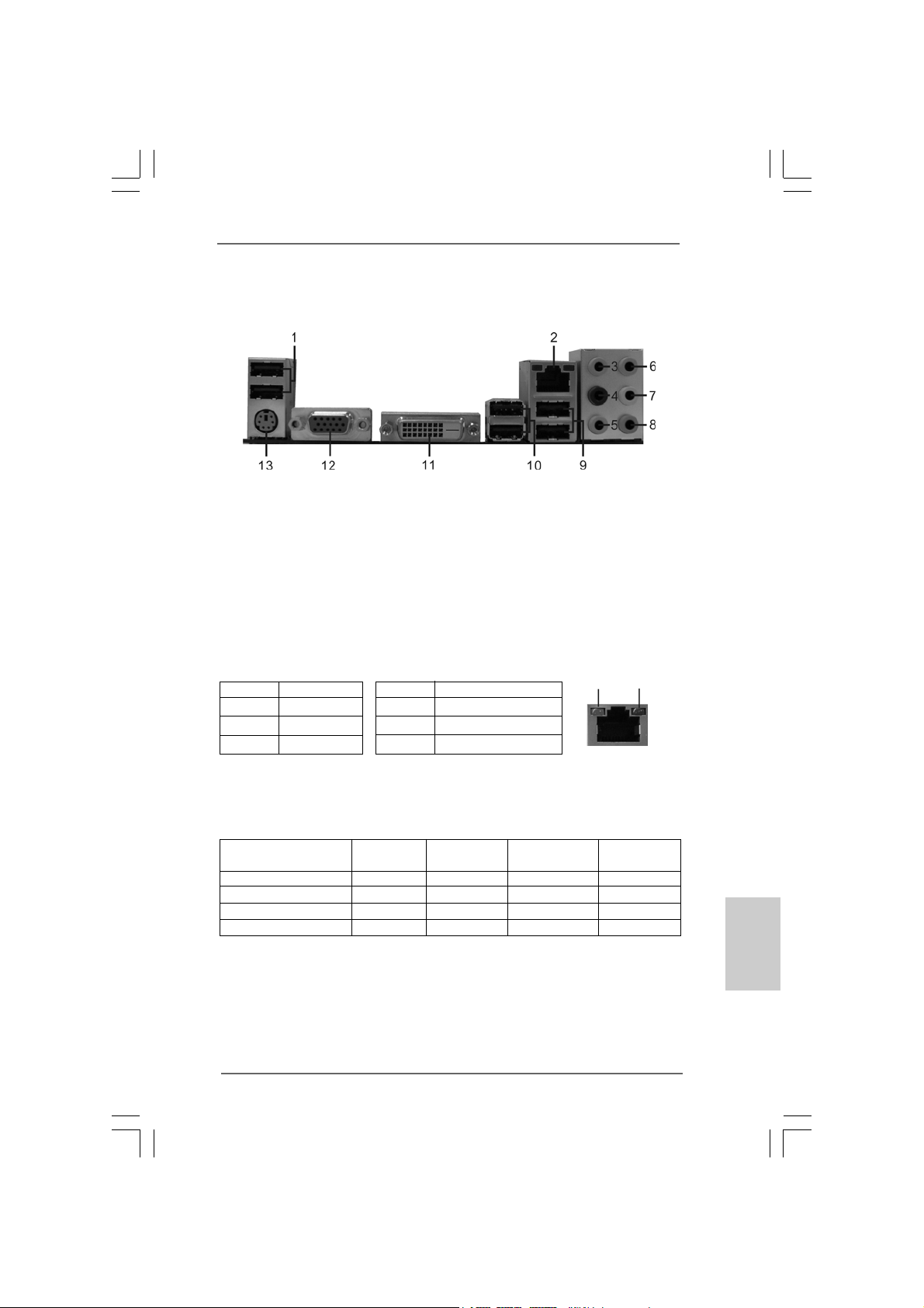
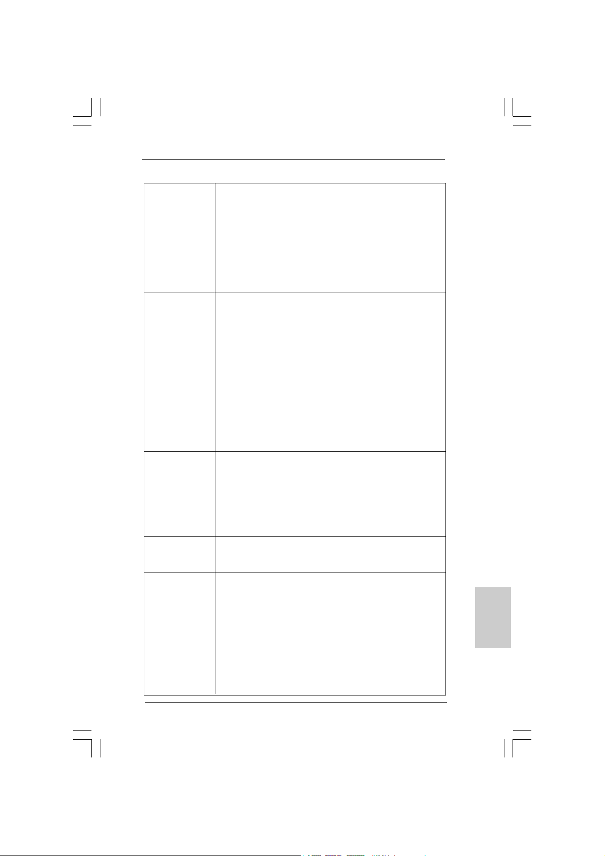
I/O PI/O P
I/O P
I/O PI/O P
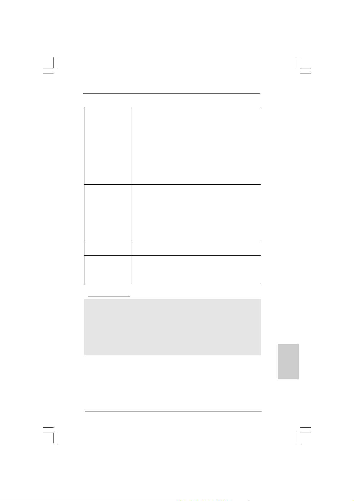
* 2 LAN RJ-45 Port 9 USB 2.0 Ports (USB01)
** 7 Front Speaker (Lime)
* There are two LED next to the LAN port. Please refer to the table below for the LAN port LED
indications.
anelanel
anel
anelanel
1 USB 2.0 Ports (USB45) 8 Microphone (Pink)
3 Side Speaker (Gray) 10 USB 2.0 Ports (USB23)
4 Rear Speaker (Black) 11 VGA/DVI-D Port
5 Central / Bass (Orange) 12 VGA/D-Sub Port
6 Line In (Light Blue) 13 PS/2 Keyboard Port (Purple)
Activity/Link LED SPEED LED
Status Description Status Description
Off No Link Off 10Mbps connection
Blinking Data Activity Orange 100Mbps connection
On Link Green 1Gbps connection
LAN Port LED Indications
ACT/LINK
LED
LAN Port
SPEED
LED
** If you use 2-channel speaker, please connect the speaker’s plug into “Front Speaker Jack”.
See the table below for connection details in accordance with the type of speaker you use.
TABLE for Audio Output Connection
Audio Output Channels Front Speaker Rear Speaker Central / Bass Side Speaker
(No. 7) (No. 4) (No. 5) (No. 3)
2 V — — -4VV-—6 VVV-8 VVVV
ASRock H55M-LE Motherboard
EnglishEnglish
EnglishEnglish
English
33
3
33
To enable Multi-Streaming function, you need to connect a front panel audio cable to the front
panel audio header. After restarting your computer, you will find “VIA HD Audio Deck” tool on
your system. Please follow below instructions according to the OS you install.
For Windows® XP / XP 64-bit OS:
Please click “VIA HD Audio Deck” icon. Click “Jack” and then click “Configuration”. In
“Configuration” screen, please check the item “Independent Headphone”.
For Windows® 7 / 7 64-bit / VistaTM / VistaTM 64-bit OS:
Please click “VIA HD Audio Deck” icon. Click “Advanced Options” on the right side on the
bottom. In “Advanced Options” screen, please check the item “Independent Headphone”.
English
EnglishEnglish
EnglishEnglish
44
4
44
ASRock H55M-LE Motherboard
1. Introduction1. Introduction
1. Introduction
1. Introduction1. Introduction
Thank you for purchasing ASRock H55M-LE motherboard, a reliable motherboard
produced under ASRock’s consistently stringent quality control. It delivers excellent
performance with robust design conforming to ASRock’s commitment to quality and
endurance.
This Quick Installation Guide contains introduction of the motherboard a nd step-by-ste p
installation guide. More detailed information of the motherboard can be f ound in the user
manual presented in the Support CD.
Because the motherboard specifications and the BIOS software might
be updated, the content of this manual will be subject to change without
notice. In case any modifications of this manual occur, the updated
version will be available on ASRock website without further notice. You
may find the latest VGA cards and CPU support lists on ASRock website
as well. ASRock website http://www.asrock.com
If you require technical support related to this motherboard, please visit
our website for specific information about the model you are using.
www.asrock.com/support/index.asp
1.1 Package Contents1.1 Package Contents
1.1 Package Contents
1.1 Package Contents1.1 Package Contents
ASRock H55M-LE Motherboard
(Micro ATX Form Factor: 9.6-in x 8.0-in, 24.4 cm x 20.3 cm)
ASRock H55M-LE Quick Installation Guide
ASRock H55M-LE Support CD
2 x Serial ATA (SATA) Data Cables (Optional)
1 x I/O Panel Shield
ASRock H55M-LE Motherboard
EnglishEnglish
EnglishEnglish
English
55
5
55
English
EnglishEnglish
EnglishEnglish
1.21.2
SpecificationsSpecifications
1.2
Specifications
1.21.2
SpecificationsSpecifications
Platform — Micro ATX Form Factor: 9.6-in x 8.0-in, 24.4 cm x 20.3 cm
— Solid Capacitor for CPU power
CPU — Supports Intel® CoreTM i7 / i5 / i3 and Pentium® G6950
Processors in LGA1156 Package
— Supports Intel® Turbo Boost Technology (see CAUTION 1)
— Supports Hyper-Threading Technology (see CAUTION 2)
— Supports Untied Overclocking Technology (see CAUTION 3)
— Supports EM64T CPU
Chipset — Intel® H55
Memory — Dual Channel DDR3 Memory Technology (see CAUTION 4)
— 2 x DDR3 DIMM slots
— Supports DDR3 2600+(OC)/2133(OC)/1866(OC)/1600/
1333/1066 non-ECC, un-buffered memory
— Max. capacity of system memory: 8GB (see CAUTION 5)
— Supports Intel® Extreme Memory Profile (XMP)
(see CAUTION 6)
Expansion Slot — 1 x PCI Express 2.0 x16 slot (5GT/s at x16 mode)
— 1 x PCI Express 2.0 x1 slot (2.5GT/s)
— 2 x PCI slots
Graphics * * Requires a Processor with Intel® Graphics Technology
— Intel® HD Graphics
— Pixel Shader 4.0, DirectX 10
— Max. shared memory 1759MB (see CAUTION 7)
— Dual VGA Output options: support DVI-D and D-Sub ports by
independent display controllers
— Supports DVI with max. resolution up to 1920×1200 @ 60Hz
— Supports D-Sub with max. resolution up to 2048×1536 @
75Hz
— Supports HDCP function with DVI port
— Supports Full HD 1080p Blu-ray (BD) / HD-DVD playback with
D VI port
— DVI port can be transferred to a HDMI 1.3 port to support
Deep Color, xvYCC and HBR audio (High Bit Rate Audio)
(Compliant HDMI monitor is required)
Audio — 7.1 CH HD Audio (VIA® VT1718S Audio Codec)
LAN — PCIE x1 Gigabit LAN 10/100/1000 Mb/s
— Realtek RTL81 11DL
— Supports Wake-On-LAN
66
6
66
ASRock H55M-LE Motherboard
Rear Panel I/O I/O Panel
— 1 x PS/2 Keyboard Port
— 1 x VGA/D-Sub Port
— 1 x VGA/DVI-D Port
— 6 x Ready-to-Use USB 2.0 Ports
— 1 x RJ-45 LAN Port with LED (ACT/LINK LED and SPEED
LED)
— HD Audio Jack: Side Speaker/Rear Speaker/Central/Bass/
Line in/Front Speaker/Microphone (see CAUTION 8)
Connector — 4 x SATAII 3.0Gb/s connectors, support NCQ, AHCI and “Hot
Plug” functions (see CAUTION 9)
— 1 x IR header
— 1 x Print Port header
— 1 x COM port header
— 1 x HDMI_SPDIF header
— 1 x Chassis Intrusion header
— CPU/Chassis/Power FAN connector
— 24 pin ATX power connector
— 4 pin 12V power connector
— Front panel audio connector
— 2 x USB 2.0 headers (support 4 USB 2.0 ports)
(see CAUTION 10)
BIOS Feature — 16Mb AMI Legal BIOS
— Supports “Plug and Play”
— ACPI 1.1 Compli ance Wake Up Events
— Supports jumperfree
— SMBIOS 2.3.1 Support
— CPU, DRAM, VTT, PCH, CPU PLL, GFX V oltage
Multi-adjustment
Support CD — Drivers, Utilities, AntiVirus Software (Trial Version),
ASRock Software Suite (CyberLink DVD Suite and Creative
Sound Blaster X-Fi MB) (OEM and Trial Version)
Unique Feature — ASRock OC Tuner (see CAUTION 11)
— Intelligent Energy Saver (see CAUTION 12)
— Instant Boot
— ASRock Instant Flash (see CAUTION 13)
— ASRock OC DNA (see CAUTION 14)
— Hybrid Booster:
— CPU Frequency Stepless Control (see CAUTION 15)
— ASRock U-COP (see CAUTION 16)
— Boot Failure Guard (B.F.G.)
— Combo Cooler Option (C.C.O.) (see CAUTION 17)
ASRock H55M-LE Motherboard
EnglishEnglish
EnglishEnglish
English
77
7
77
— Good Night LED
— Turbo 50 / Turbo 100 GPU Overclocking (Requires a
Processor with Intel® Graphics Technology)
Hardware — CPU Temperature Sensing
Monitor — Chassis Temperature Sensing
— CPU/Chassis/Power Fan Tachometer
— CPU Quiet Fan
— CPU/Chassis Fan Multi-Speed Control
— CASE OPEN detection
— Voltage Monitoring: +12V, +5V, +3.3V, CPU Vcore
OS — Microsoft® Windows® 7 / 7 64-bit / Vista
TM
/ VistaTM 64-bit
/ XP / XP 64-bit compliant
Certifications — FCC, CE, WHQL
— EuP Ready (EuP ready power supply is required)
(see CAUTION 18)
* For detailed product information, please visit our website: http://www.asrock.com
WARNING
Please realize that there is a certain risk involved with overclocking, including adjusting
the setting in the BIOS, applying Untied Overclocking Technology, or using the thirdparty overclocking tools. Overclocking may affect your system stability, or even
cause damage to the components and devices of your system. It should be done at
your own risk and expense. We are not responsible for possible damage caused by
overclocking.
English
EnglishEnglish
EnglishEnglish
88
8
88
ASRock H55M-LE Motherboard
CAUTION!
1. Intel® CoreTM i3 and Pentium® G6950 processors do not support Intel
Turbo Boost Technology.
2. About the setting of “Hyper Threading Technology”, please check page 39
of “User Manual” in the support CD.
3. This motherboard supports Untied Overclocking Technology. Please read
“Untied Overclocking Technology” on page 22 for details.
4. This motherboard supports Dual Channel Memory Technology. Before you
implement Dual Channel Memory Technology, make sure to read the
installation guide of memory modules on page 14 for proper installation.
5. Due to the operating system limitation, the actual memory size may be
less than 4GB for the reservation for system usage under Windows® 7 /
VistaTM / XP. For Windows® OS with 64-bit CPU, there is no such limitation.
6. For those CPU that only support up to DDR3 1333, the XMP DDR3 1600
is supported through overclocking.
7. The maximum shared memory size is defined by the chipset vendor and
is subject to change. Please check Intel® website for the latest information.
8. For microphone input, this motherboard supports both stereo and mono
modes. For audio output, this motherboard supports 2-channel, 4-channel,
6-channel, and 8-channel modes. Please check the table on page 3 for
proper connection.
9. Before installing SATAII hard disk to SATAII connector, please read the
“SATAII Hard Disk Setup Guide” on page 26 of “User M a nual” in the support
CD to adjust your SATAII hard disk drive to SATAII mode. You can also
connect SATA hard disk to SATAII connector directly.
10. Power Management for USB 2.0 works fine under Microsoft® Windows® 7
64-bit / 7 / VistaTM 64-bit / VistaTM / XP 64-bit / XP SP1 or SP2.
11. It is a user-friendly ASRock overclocking tool which allows you to surveil
your system by hardware monitor function and overclock your hardware
devices to get the best system performance under Windows® environment.
Please visit our website for the operation procedures of ASRock OC
Tuner.
ASRock website: http://www.asrock.com/feature/OCTuner/index.htm
12. Featuring an advanced proprietary hardware and software design,
Intelligent Energy Saver is a revolutionary technology that delivers
unparalleled power savings. In other words, it is able to provide exceptional
power saving and improve power efficiency without sacrificing computing
performance. Please visit our website for the operation procedures of
Intelligent Energy Saver.
ASRock website: http://www.asrock.com/feature/IES/index.html
®
EnglishEnglish
EnglishEnglish
English
ASRock H55M-LE Motherboard
99
9
99
English
EnglishEnglish
EnglishEnglish
13. ASRock Instant Flash is a BIOS flash utility embedded in Flash ROM.
This convenient BIOS update tool allows you to update system BIOS
without entering operating systems first like MS-DOS or Windows®. With
this utility, you can press <F6> key during the POST or press <F2> key to
BIOS setup menu to access ASRock Instant Flash. Just launch this tool
and save the new BIOS file to your USB flash drive, floppy disk or hard
drive, then you can update your BIOS only in a few clicks without preparing an additional floppy diskette or other complicated flash utility. Please
be noted that the USB flash drive or hard drive must use FAT32/16/12 file
system.
14. The software name itself – OC DNA literally tells you what it is capable of.
OC DNA, an exclusive utility developed by ASRock, provides a convenient way for the user to record the OC settings and share with others. It
helps you to save your overclocking record under the operating system
and simplifies the complicated recording process of overclocking settings.
With OC DNA, you can save your OC settings as a profile and share with
your friends! Your friends then can load the OC profile to their own system
to get the same OC settings as yours! Please be noticed that the OC
profile can only be shared and worked on the same motherboard.
15. Although this motherboard offers stepless control, it is not recommended
to perform over-clocking. Frequencies other than the recommended CPU
bus frequencies may cause the instability of the system or damage the
CPU.
16. While CPU overheat is detected, the system will automatically shutdown.
Before you resume the system, please check if the CPU fan on the
motherboard functions properly and unplug the power cord, then plug it
back again. To improve heat dissipation, remember to spray thermal
grease between the CPU a nd the he atsink when you install the PC syste m.
17. Combo Cooler Option (C.C.O.) provides the flexible option to adopt two
different CPU cooler types, Socket LGA 775 and LGA 1156. Please be
noticed that not all the 775 CPU Fan can be used.
18. EuP, stands for Energy Using Product, was a provision regulated by
European Union to define the power consumption for the completed system.
According to EuP, the total AC power of the completed system shall be
under 1.00W in off mode condition. To meet EuP standard, an EuP ready
motherboard and an EuP ready power supply are required. According to
Intel’s suggestion, the EuP ready power supply must meet the standard of
5v standby power efficiency is higher than 50% under 100 mA current
consumption. For EuP ready power supply selection, we recommend you
checking with the power supply manufacturer for more details.
1010
10
1010
ASRock H55M-LE Motherboard
2.2.
InstallationInstallation
2.
Installation
2.2.
InstallationInstallation
Pre-installation PrecautionsPre-installation Precautions
Pre-installation Precautions
Pre-installation PrecautionsPre-installation Precautions
Take note of the following precautions before you install motherboard components or change any motherboard settings.
1. Unplug the power cord from the wall socket before touching any
component. Failure to do so may cause severe damage to the
motherboard, peripherals, and/or components.
2. To avoid damaging the motherboard components due to static
electricity, NEVER place your motherboard directly on the carpet
or the like. Also remember to use a grounded wrist strap or touch
a safety grounded object before you handle components.
3. Hold components by the edges and do not touch the ICs.
4. Whenever you uninstall any component, place it on a grounded
antstatic pad or in the bag that comes with the component.
5. When placing screws into the screw holes to secure the
motherboard to the chassis, please do not over-tighten the
screws! Doing so may damage the motherboard.
2.12.1
CPU InstallationCPU Installation
2.1
CPU Installation
2.12.1
CPU InstallationCPU Installation
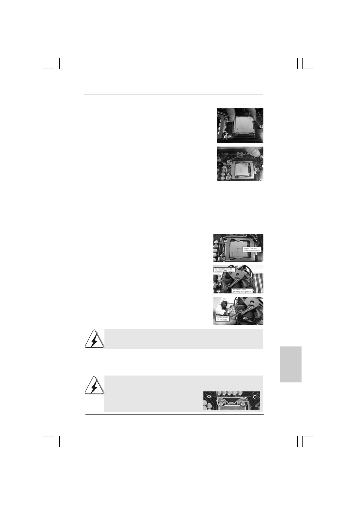
For the installation of Intel 1156-Pin CPU,
please follow the steps below.
1156-Pin Socket Overview
Before you insert the 1156-Pin CPU into the socket, please check if
the CPU surface is unclean or if there is any bent pin on the socket.
Do not force to insert the CPU into the socket if above situation is
found. Otherwise, the CPU will be seriously damaged.
ASRock H55M-LE Motherboard
1111
11
1111
EnglishEnglish
EnglishEnglish
English
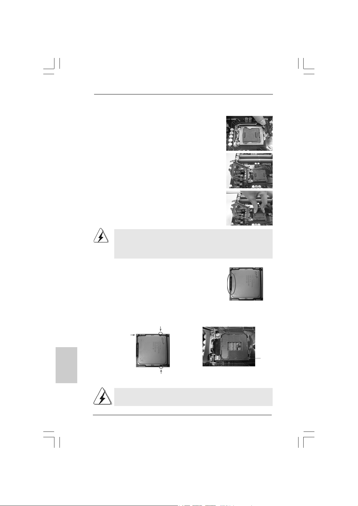
Step 1. Open the socket:
Step 1-1. Disengaging the lever by depressing
down and out on the hook to clear retention tab.
Step 1-2. Rotate the load lever to fully open posi-
tion at approxi mately 135 degrees .
Step 1-3. Rotate the load plate to fully open posi-
tion at approxi mately 100 degrees .
Step 2. Remove PnP Cap (Pick a nd Pla ce Cap).
1. It is recommended to use the cap tab to handle and avoid kicking
off the PnP cap.
2. This cap must be placed if returning the motherboard for after
service.
Step 3. Insert the 1 156-Pin CPU:
Step 3-1. Hold the CPU by the edges where are
marked with black lines.
black line
English
EnglishEnglish
EnglishEnglish
1212
12
1212
Step 3-2. Orient the CPU with IHS (Integrated Heat
Sink) up. Locate Pin1 and the two orientation key notches.
orientation key notch
Pin1
orientation key notch
1156-Pin CPU
For proper inserting, please ensure to match the two orientation key
notches of the CPU with the two alignment keys of the socket.
1156-Pin Socket
ASRock H55M-LE Motherboard
alignment key
Pin1
alignment key
Step 3-3. Carefully pla ce the CPU into the socket
by using a purely vertical motion.
Step 3-4. V erify that the CPU is within the socket
and properly mated to the orient keys.
Step 4. Close the socket:
Step 4-1. Rotate the load plate onto the IHS.
Step 4-2. While pressing down lightly on load
plate, engage the load lever.
Step 4-3. Secure load lever with load plate tab
under retention tab of load lever.
2.22.2
Installation of CPU Fan and HeatsinkInstallation of CPU Fan and Heatsink
2.2
Installation of CPU Fan and Heatsink
2.22.2
Installation of CPU Fan and HeatsinkInstallation of CPU Fan and Heatsink
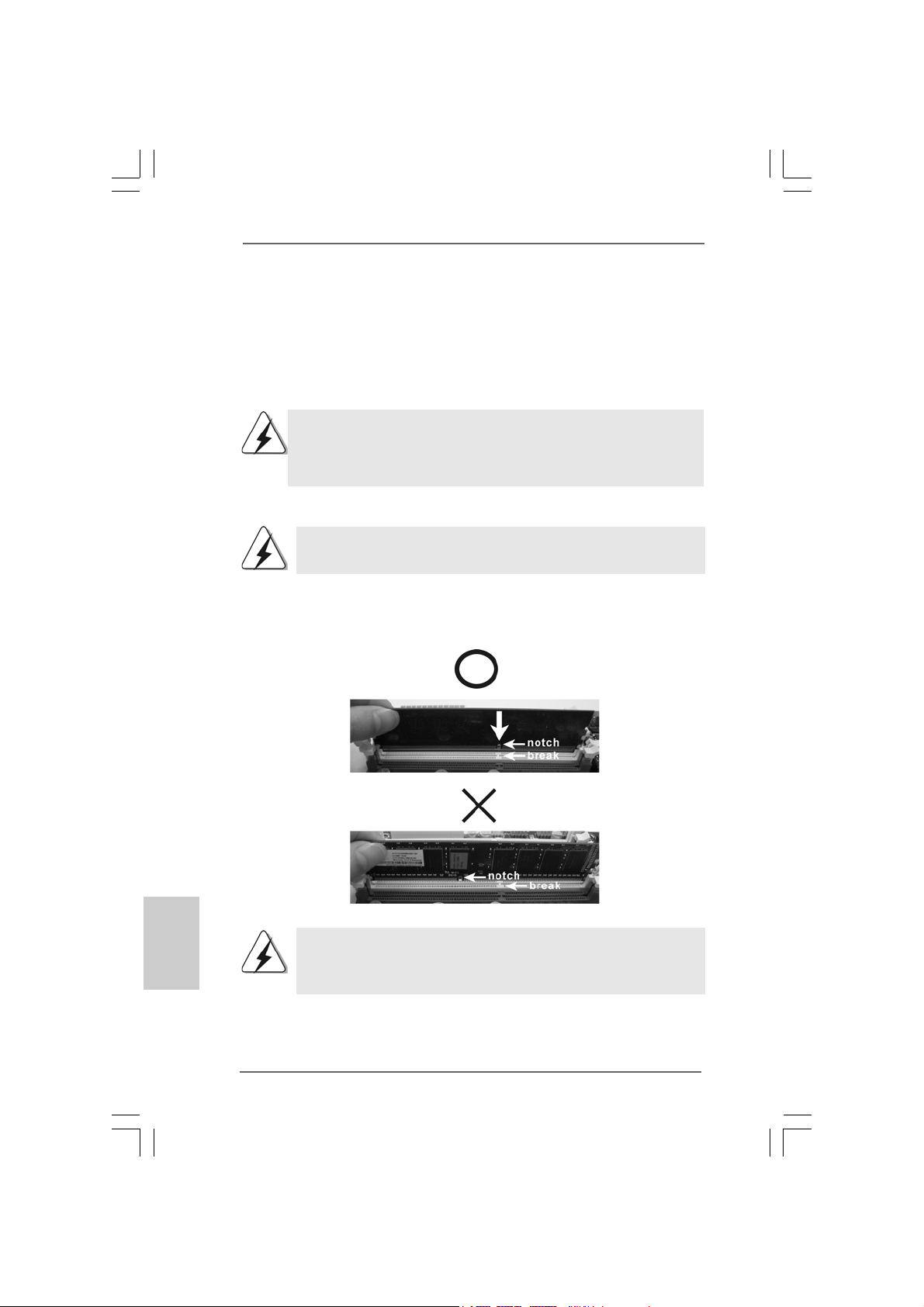
For proper installation, plea se kindly refer to the instruction ma nuals of your CPU fan a nd
heatsink.
Below is an example to illustrate the installation of the heatsink for 1156-Pin CPU.
Step 1. Apply thermal interfa ce materi al onto center of
IHS on the socket surface.
Step 2. Place the heatsink onto the socket. Ensure
fan cables are oriented on side closest to the
CPU fan connector on the motherboard
(CPU_FAN1, see page 2, No. 3).
Step 3. Align fa steners with the motherboard
throughholes.
Step 4. Rotate the fa stener clockwise, then press down
on fastener caps with thumb to install and lock.
Repeat with remaining fasteners.
If you press down the fasteners without rotating them clockwise,
the heatsink cannot be secured on the motherboard.
Step 5. Connect fan header with the CPU fan connector on the motherboard.
Step 6. Secure excess cable with tie-wrap to ensure cable does not interfere with
fan operation or contact other components.
Please be noticed that this motherboard supports Combo Cooler
Option (C.C.O.), which provides the flexible option to adopt two
different CPU cooler types, Socket LGA
775 and LGA 1156. The white throughholes
are for Socket LGA 1156 CPU fan.
ASRock H55M-LE Motherboard
1313
13
1313
EnglishEnglish
EnglishEnglish
English
2.3 Installation of Memory Modules (DIMM)2.3 Installation of Memory Modules (DIMM)
2.3 Installation of Memory Modules (DIMM)
2.3 Installation of Memory Modules (DIMM)2.3 Installation of Memory Modules (DIMM)
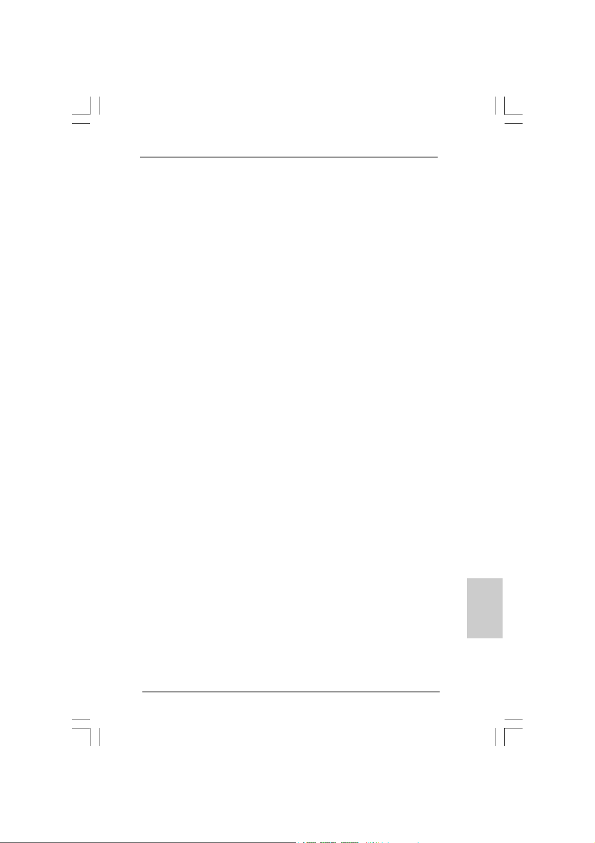
H55M-LE motherboard provides two 240-pin DDR3 (Double Data Rate 3) DIMM slots,
and supports Dual Channel Memory Technology. For dual channel configuration, you
always need to install two identical (the same brand, speed, size and chip-type)
memory modules in the DD R3 DIMM slots to a ctivate Dual Cha nnel Memory Technology .
Otherwise, it will operate at single channel mode.
1. It is not allowed to install a DDR or DDR2 memory module into
DDR3 slot;otherwise, this motherboard and DIMM may be damaged.
2. If you install only one memory module or two non-identical memory
modules, it is unable to a ctivate the Dual Cha nnel Memory Technology .
Installing a DIMMInstalling a DIMM
Installing a DIMM
Installing a DIMMInstalling a DIMM
Please make sure to disconnect power supply before adding or
removing DIMMs or the system components.
Step 1. Unlock a DIMM slot by pressing the retaining clips outward.
Step 2. Align a DIMM on the slot such that the notch on the DIMM matches the break
on the slot.
English
EnglishEnglish
EnglishEnglish
1414
14
1414
The DIMM only fits in one correct orientation. It will cause permanent
damage to the motherboard and the DIMM if you force the DIMM into the
slot at incorrect orientation.
Step 3. Firmly insert the DIMM into the slot until the retaining clips at both ends fully
snap back in place and the DIMM is properly seated.
ASRock H55M-LE Motherboard
2.4 Expansion Slots (PCI and PCI Express Slots)2.4 Expansion Slots (PCI and PCI Express Slots)
2.4 Expansion Slots (PCI and PCI Express Slots)
2.4 Expansion Slots (PCI and PCI Express Slots)2.4 Expansion Slots (PCI and PCI Express Slots)
There are 2 PCI slots and 2 PCI Express slots on this motherboard.
PCI slot: PCI slot is used to install expansion cards that have the 32-bit PCI
interface.
PCIE slots:
PCIE1 (PCIE x16 slot; Blue) is used for PCI Express x16 lane width
graphics cards.
PCIE2 (PCIE x1 slot; White) is used for PCI Express cards with x1 lane
width cards, such as Gigabit LAN card, SATA2 card, etc.
Installing an expansion cardInstalling an expansion card
Installing an expansion card
Installing an expansion cardInstalling an expansion card
Step 1. Before installing the expansion card, please make sure that the power
supply is switched off or the power cord is unplugged. Please read the
documentation of the expansion card and make necessary hardware
settings for the card before you start the installation.
Step 2. Remove the system unit cover (if your motherboard is already installed in
a chassis).
Step 3. Remove the bracket facing the slot that you intend to use. Keep the
screws for later use.
Step 4. Align the card connector with the slot and press firmly until the card is
completely seated on the slot.
Step 5. Fasten the card to the chassis with screws.
Step 6. Replace the system cover.
ASRock H55M-LE Motherboard
1515
15
1515
EnglishEnglish
EnglishEnglish
English
2.5 Jumpers Setup2.5 Jumpers Setup
2.5 Jumpers Setup
2.5 Jumpers Setup2.5 Jumpers Setup
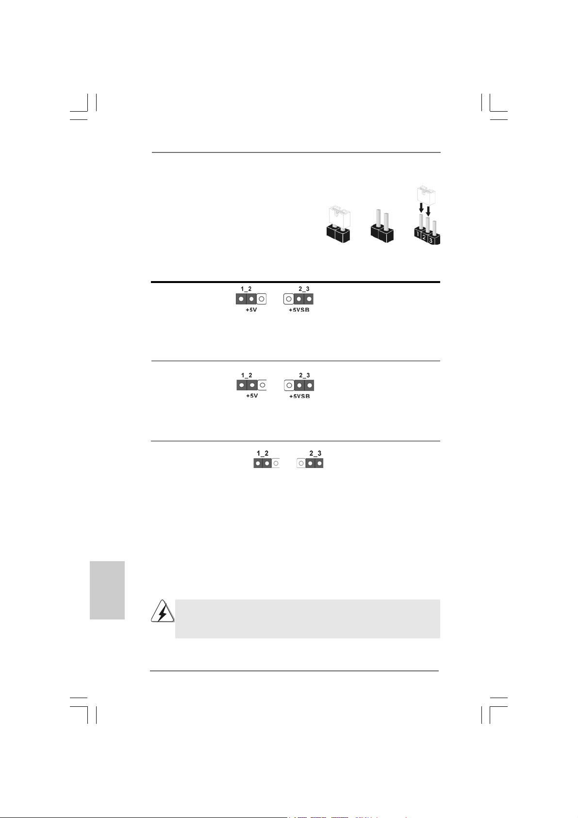
The illustration shows how jumpers are
setup. When the jumper cap is placed on
pins, the jumper is “Short”. If no jumper cap
is placed on pins, the jumper is “Open”. The
illustration shows a 3-pin jumper whose pin1
and pin2 are “Short” when jumper cap is
placed on these 2 pins.
Jumper Setting Description
PS2_USB_PWR1 Short pin2, pin3 to enable
(see p.2, No. 2) +5VSB (standby) for PS/2
Note: To select +5VSB, it requires 2 Amp and higher standby current provided by
power supply.
USB_PWR1 (PORT 6-9) Short pin2, pin3 to enable
(see p.2, No. 19) +5VSB (standby) for
Note: To select +5VSB, it requires 2 Amp and higher standby current provided by
power supply.
Clear CMOS Jumper
(CLRCMOS1)
(see p.2 No. 16)
Clear CMOSDefault
Short Open
or I/O panel USB wake up
events.
USB6_7 and USB8_9 wake
up events.
English
EnglishEnglish
EnglishEnglish
Note: CLRCMOS1 allows you to clear the data in CMOS. The data in CMOS includes
system setup information such as system password, date, time, and system
setup parameters. To clear and reset the system parameters to default setup,
please turn of f the computer and unplug the power cord from the power supply.
After waiting for 15 seconds, use a jumper ca p to short pin2 and pin3 on CLRCMOS1
for 5 seconds. However , please do not clear the CMOS right after you update the
BIOS. If you need to clear the CMOS when you just finish updating the BIOS, you
must boot up the system first, and then shut it down before you do the clearCMOS action.
If you clear the CMOS, the case open may be detected. Please adjust
the BIOS option “Clear Status” to clear the record of previous chassis
intrusion status.
1616
16
1616
ASRock H55M-LE Motherboard
2.6 Onboard Headers and Connectors2.6 Onboard Headers and Connectors
2.6 Onboard Headers and Connectors
2.6 Onboard Headers and Connectors2.6 Onboard Headers and Connectors
Onboard headers and connectors are NOT jumpers. Do NOT place
jumper caps over these headers and connectors. Placing jumper caps
over the headers and connectors will cause permanent damage of the
motherboard!
Serial A T AII Connectors These four Serial AT AII (SAT AII)
(SAT AII_1: see p.2, No. 1 1) connectors support SATA data
(SAT AII_2: see p.2, No. 10) cables for internal storage
(SAT AII_3: see p.2, No. 12) devices. The current SATAII
(SAT AII_4: see p.2, No. 13) interface allows up to 3.0 Gb/s
data transfer rate.
SAT AII_4 SA TAII_2
SAT AII_3 SA TAII_1
Serial A TA (SA TA) Either end of the SATA data cable
Data Cable can be connected to the SATA /
(Optional) SATAII hard disk or the SATAII
connector on this motherboard.
USB 2.0 Headers Besides six default USB 2.0
(9-pin USB8_9) ports on the I/O panel, there are
(see p.2 No. 20) two USB 2.0 headers on this
motherboard. Each USB 2.0
header can support two USB
2.0 ports.
(9-pin USB6_7)
(see p.2 No. 18)
Print Port Header This is an interface for print
(25-pin LPT1) port cable that allows
(see p.2 No. 23) convenient connection of printer
devices.
ASRock H55M-LE Motherboard
1717
17
1717
EnglishEnglish
EnglishEnglish
English
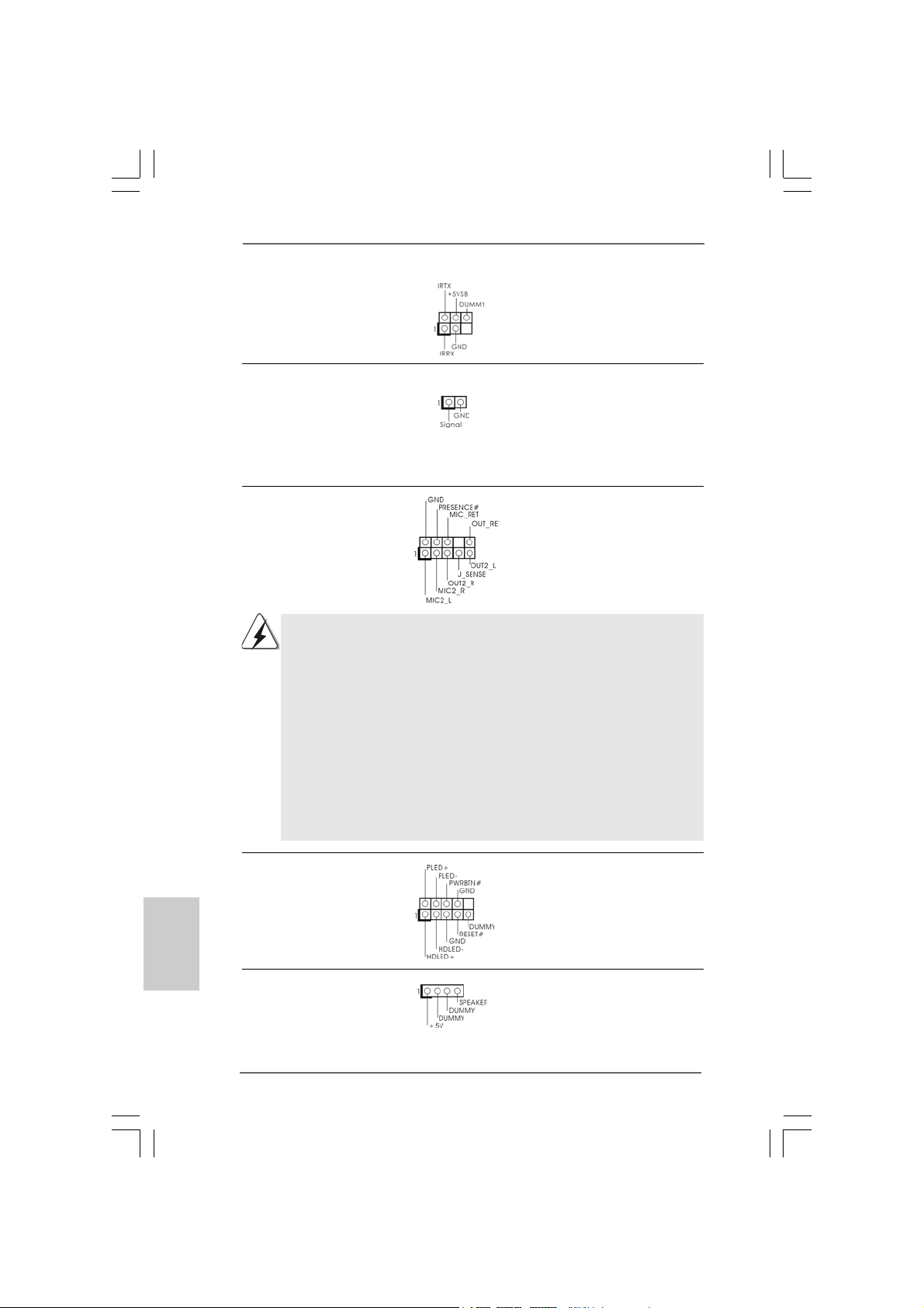
Infrared Module Header This header supports an optional
(5-pin IR1) wireless transmitting and
(see p.2 No. 21) receiving infrared module.
Chassis Intrusion Header This motherboard supports
(2-pin CI1) CASE OPEN detection feature
(see p.2 No. 22) that detects if the chassis cover
has been removed. This feature
requires a chassis with chassis
intrusion detection design.
Front Panel Audio Header This is an interface for front
(9-pin HD_AUDIO1) panel audio cable that allows
(see p.2 No. 28) convenient connection and
control of audio devices.
1. High Definition Audio supports Jack Sensing, but the panel wire on
the chassis must support HDA to function correctly. Please follow the
instruction in our manual and chassis manual to install your system.
2. If you use AC’97 audio panel, please install it to the front panel audio
header as below:
A. Connect Mic_IN (MIC) to MIC2_L.
B. Connect Audio_R (RIN) to OUT2_R and Audio_L (LIN) to OUT2_L.
C. Connect Ground (GND) to Ground (GND).
D. MIC_RET and OUT_RET are for HD audio panel only. You don’t
need to connect them for AC’97 audio panel.
E. Enter BIOS Setup Utility. Enter Advanced Settings, and then select
Chipset Configuration. Set the Front Panel Control option from
[Auto] to [Enabled].
English
EnglishEnglish
EnglishEnglish
System Panel Header This header accommodates
(9-pin PANEL1) several system front panel
(see p.2 No. 15) functions.
Chassis Speaker Header Please connect the chassis
(4-pin SPEAKER 1) speaker to this header.
(see p.2 No. 14)
1818
18
1818
ASRock H55M-LE Motherboard
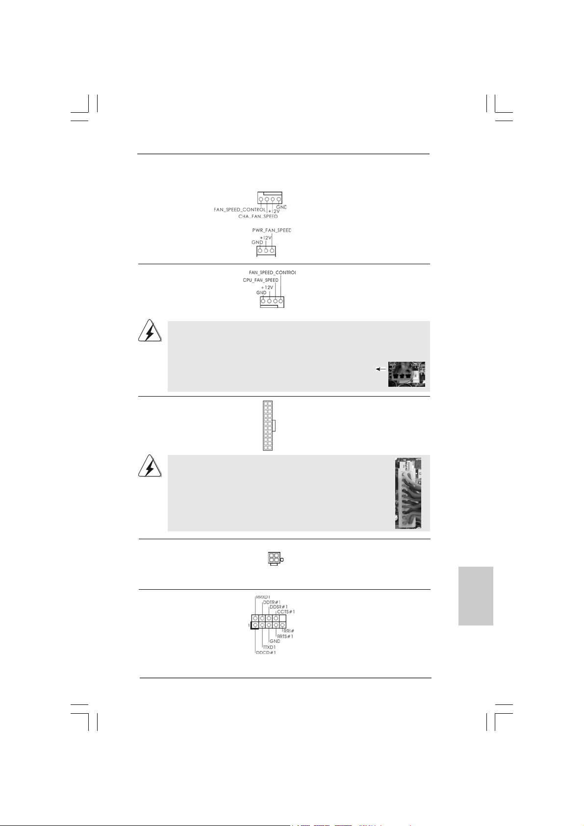
Chassis and Power Fan Connectors Please connect the fan cables
(4-pin CHA_FAN1) to the fan connectors and
(see p.2 No. 17) match the black wire to the
ground pin.
(3-pin PWR_FAN1)
(see p.2 No. 4)
CPU Fan Connector Please connect a CPU fan cable
(4-pin CPU_FAN1) to this connector and match
(see p.2 No. 3) the black wire to the ground pin.
1 2 3 4
Though this motherboard provides 4-Pin CPU fan (Quiet Fan) support, the 3-Pin
CPU fan still can work successfully even without the fan speed control function.
If you plan to connect the 3-Pin CPU fan to the CPU fan connector on this
motherboard, please connect it to Pin 1-3.
Pin 1-3 Connected
3-Pin Fan Installation
ATX Power Connector Please connect an ATX power
(24-pin ATXPW R1) supply to this connector.
(see p.2, No. 7)
Though this motherboard provides 24-pin ATX power connector,
12 124
13
12
24
it can still work if you adopt a traditional 20-pin ATX power supply.
To use the 20-pin ATX power supply, please plug your
power supply along with Pin 1 and Pin 13.
20-Pin A TX Power Supply Installation
1
13
ATX 12V Power Connector Please connect an ATX 12V
(4-pin A TX12V1) power supply to this connector.
(see p.2 No. 1)
Serial port Header This COM1 header supports a
(9-pin COM1) serial port module.
(see p.2 No.24)
ASRock H55M-LE Motherboard
1919
19
1919
EnglishEnglish
EnglishEnglish
English
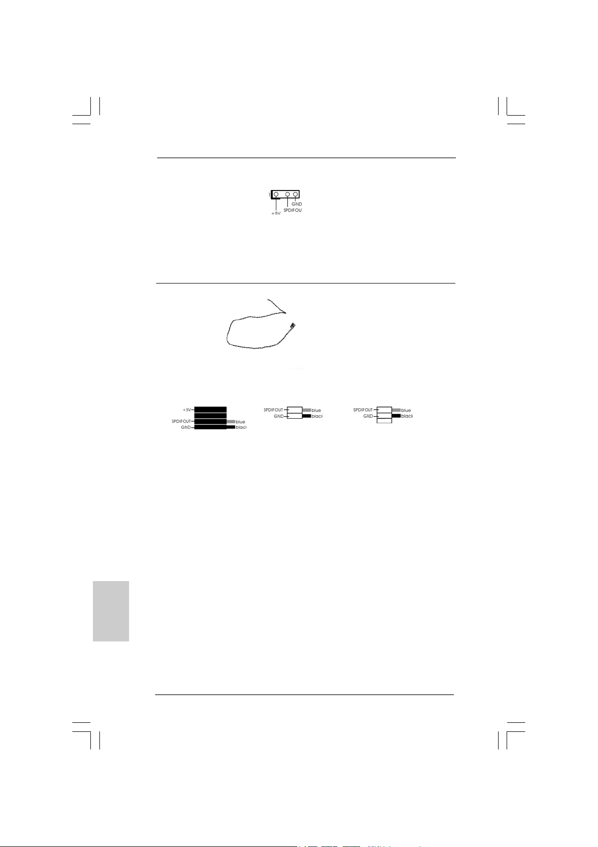
HDMI_SPDIF Header HDMI_SPDIF header, providing
(3-pin HDMI_SPDIF1) SPDIF audio output to HDMI V GA
(see p.2 No. 29) card, allows the system to
connect HDMI Digital TV/
projector/LCD devices. Please
connect the HDMI_SPDIF
connector of HDMI VGA card to
this header.
HDMI_SPDIF Cable Please connect the black end (A)
(Optional) of HDMI_SPDIF cable to the
C
B
A
HDMI_SPDIF header on the
motherboard. Then connect the
white end (B or C) of
HDMI_SPDIF cable to the
HDMI_SPDIF connector of HDMI
VGA card.
A. black end B. white end (2-pin) C. white end (3-pin)
English
EnglishEnglish
EnglishEnglish
2020
20
2020
ASRock H55M-LE Motherboard
2.72.7
Driver Installation Guide Driver Installation Guide
2.7
Driver Installation Guide
2.72.7
Driver Installation Guide Driver Installation Guide
To install the drivers to your system, please insert the support CD to your optical
drive first. Then, the drivers compatible to your system can be auto-detected and
listed on the support CD driver page. Please follow the order from up to bottom
side to install those required drivers. Therefore, the drivers you install can work
properly.
2.82.8
Installing WindowsInstalling Windows
2.8
Installing Windows
2.82.8
Installing WindowsInstalling Windows
TMTM
TM
TMTM
VistaVista
Vista
VistaVista
If you want to install Windows® 7 / 7 64-bit / VistaTM / VistaTM 64-bit / XP / XP 64-bit OS
on your SATA / SATAII HDDs, please follow below procedures according to the OS
you install.
2.8.1 Installing Windows2.8.1 Installing Windows
2.8.1 Installing Windows
2.8.1 Installing Windows2.8.1 Installing Windows
If you want to install Windows® XP / XP 64-bit OS on your SATA / SATAII HDDs, plea se
follow below steps.
Using SATA / SATAII HDDs without NCQ function (IDE mode)
STEP 1: Set up BIOS.
A. Enter BIOS SETUP UTILITY Advanced screen Storage Configuration.
B. Set the option “SATA Operation Mode” to [IDE].
STEP 2: Install Windows® XP / XP 64-bit OS on your system.
2.8.2 Installing Windows2.8.2 Installing Windows
2.8.2 Installing Windows
2.8.2 Installing Windows2.8.2 Installing Windows
Vista Vista
Vista
Vista Vista
If you want to install Windows® 7 / 7 64-bit / VistaTM / VistaTM 64-bit OS on your SATA
/ SATAII HDDs, please follow below steps.
64-bit / XP / XP 64-bit 64-bit / XP / XP 64-bit
64-bit / XP / XP 64-bit
64-bit / XP / XP 64-bit 64-bit / XP / XP 64-bit
AHCI mode is not supported under Windows® XP / XP 64-bit OS.
TMTM
TM
TMTM
64-bit 64-bit
64-bit
64-bit 64-bit
®
7 / 7 64-bit / Vista 7 / 7 64-bit / Vista
7 / 7 64-bit / Vista
7 / 7 64-bit / Vista 7 / 7 64-bit / Vista
®
XP / XP 64-bit XP / XP 64-bit
XP / XP 64-bit
XP / XP 64-bit XP / XP 64-bit
®
7 / 7 64-bit / Vista 7 / 7 64-bit / Vista
7 / 7 64-bit / Vista
7 / 7 64-bit / Vista 7 / 7 64-bit / Vista
TM TM
TM
TM TM
TM TM
TM
TM TM
//
/
//
//
/
//
Using SATA / SATAII HDDs without NCQ function (IDE mode)
STEP 1: Set up BIOS.
A. Enter BIOS SETUP UTILITY Advanced screen Storage Configuration.
B. Set the option “SATA Operation Mode” to [IDE].
STEP 2: Install Windows® 7 / 7 64-bit / VistaTM / VistaTM 64-bit OS on your
system.
ASRock H55M-LE Motherboard
2121
21
2121
EnglishEnglish
EnglishEnglish
English
Using SATA / SATAII HDDs with NCQ function (AHCI mode)
STEP 1: Set Up BIOS.
A. Enter BIOS SETUP UTILITY Advanced screen Storage Configuration.
B. Set the option “SATA Operation Mode” to [AHCI].
STEP 2: Install Windows® 7 / 7 64-bit / VistaTM / VistaTM 64-bit OS on your
system.
2.92.9
Untied Overclocking TechnologyUntied Overclocking Technology
2.9
Untied Overclocking Technology
2.92.9
Untied Overclocking TechnologyUntied Overclocking Technology
This motherboard supports Untied Overclocking Technology, which means during
overclocking, FSB enjoys better margin due to fixed PCI / PCIE buses. Before you
enable Untied Overclocking function, please enter “Overclock Mode” option of BIOS
setup to set the selection from [Auto] to [Manual]. Therefore, CPU FSB is untied
during overclocking, but PCI / PCIE buses are in the fixed mode so that FSB can
operate under a more stable overclocking environment.
Please refer to the warning on page 8 for the possible overclocking risk
before you apply Untied Overclocking Technology.
English
EnglishEnglish
EnglishEnglish
2222
22
2222
ASRock H55M-LE Motherboard

3. BIOS Information3. BIOS Information
3. BIOS Information
3. BIOS Information3. BIOS Information
The Flash Memory on the motherboard stores BIOS Setup Utility. When you start up
the computer, please press <F2> during the Power-On-Self-Test (POST) to enter
BIOS Setup utility; otherwise, POST continues with its test routines. If you wish to
enter BIOS Setup after POST, please restart the system by pressing <Ctl> + <Alt> +
<Delete>, or pressing the reset button on the system chassis. The BIOS Setup
program is designed to be user-friendly. It is a menu-driven program, which allows
you to scroll through its various sub-menus and to select among the predetermined
choices. For the detailed information about BIOS Setup, please refer to the User
Manual (PDF file) contained in the Support CD.
4. Sof4. Sof
4. Sof
4. Sof4. Sof
This motherboard supports various Microsoft® Windows® operating systems: 7 /
7 64-bit / VistaTM / Vista
motherboard contains necessary drivers and useful utilities that will enhance
motherboard features. To begin using the Support CD, insert the CD into your CDROM drive. It will display the Main Menu automatically if “AUTORUN” is enabled in
your computer. If the Main Menu does not appear automatically, locate and doubleclick on the file “ASSETUP.EXE” from the BIN folder in the Support CD to display the
menus.
tware Supportware Suppor
tware Suppor
tware Supportware Suppor
TM
64-bit / XP / XP 64-bit. The Support CD that came with the
t CD informationt CD information
t CD information
t CD informationt CD information
EnglishEnglish
EnglishEnglish
English
ASRock H55M-LE Motherboard
2323
23
2323
1. Einführung1. Einführung
1. Einführung
1. Einführung1. Einführung
Wir danken Ihnen für den Kauf des ASRock H55M-LE Motherboard, e in zuverlässiges
Produkt, welches unter den ständigen, strengen Qualitätskontrollen von ASRock
gefertigt wurde. Es bietet Ihnen exzellente Leistung und robustes De sign, ge mäß der
Verpflichtung von ASRock zu Qualität und Halbarkeit. Diese
Schnellinstallationsanleitung führt in das Motherboard und die schrittweise Installation ein. Details über das Motherboard finden Sie in der Bedienungsanleitung auf der
Support-CD.
Da sich Motherboard-Spezifikationen und BIOS-Software verändern
können, kann der Inhalt dieses Handbuches ebenfalls jederzeit geändert
werden. Für den Fall, dass sich Änderungen an diesem Handbuch
ergeben, wird eine neue Version auf der ASRock-Website, ohne weitere
Ankündigung, verfügbar sein. Die neuesten Grafikkarten und unterstützten
CPUs sind auch auf der ASRock-Website aufgelistet.
ASRock-Website: http://www.asrock.com
Wenn Sie technische Unterstützung zu Ihrem Motherboard oder spezifische
Informationen zu Ihrem Modell benötigen, besuchen Sie bitte unsere
Webseite:
www.asrock.com/support/index.asp
1.1 Kartoninhalt1.1 Kartoninhalt
1.1 Kartoninhalt
1.1 Kartoninhalt1.1 Kartoninhalt
ASRock H55M-LE Motherboard
(Micro ATX-Formfaktor: 24.4 cm x 20.3 cm; 9.6 Zoll x 8.0 Zoll)
ASRock H55M-LE Schnellinstallationsanleitung
ASRock H55M-LE Support-CD
Zwei Serial ATA (SATA) -Datenkabel (optional)
Ein I/O Shield
Deutsch
DeutschDeutsch
DeutschDeutsch
2424
24
2424
ASRock H55M-LE Motherboard
1.21.2
SpezifikationenSpezifikationen
1.2
Spezifikationen
1.21.2
SpezifikationenSpezifikationen
Plattform — Micro ATX-Formfaktor: 24.4 cm x 20.3 cm; 9.6 Zoll x 8.0 Zoll
— Festkondensator für CPU-Leistung
CPU — Unterstützt Intel® CoreTM i7 / i5 / i3 und Pentium® G6950-
Prozessoren im LGA1156-Package
— Unterstützt Intel® Turbo Boost-Technologie
(siehe VORSICHT 1)
— Unterstützt Hyper-Threading-Technologie
(siehe VORSICHT 2)
— Unterstützt Untied-Übertaktungstechnologie
(siehe VORSICHT 3)
— Unterstützt EM64T -CPU
Chipsatz — Intel® H55
Speicher — Unterstützung von Dual-Kanal-Speichertechnologie
(siehe VORSICHT 4)
— 2 x Steckplätze für DDR3
— Unterstützt DDR3 2600+(OC)/2133(OC)/1866(OC)/1600/
1333/1066 non-ECC, ungepufferter Speicher
— Max. Kapazität des Systemspeichers: 8GB
(siehe VORSICHT 5)
— Unterstützt Intel® Extreme Memory Profile (XMP)
(siehe VORSICHT 6)
Erweiterungs- — 1 x PCI Express 2.0 x16-Steckplatz (5GT/s im x16-Modus)
steckplätze — 1 x PCI Express 2.0 x1-Steckplatz (2,5 GT/s)
— 2 x PCI -Steckplatz
Onboard-VGA * * Benötigt einen Prozessor mit Intel®-Grafiktechnologie
— Intel® Grafikmedienbeschleuniger HD
— Pixel Shader 4.0, DirectX 10
— Maximal gemeinsam genutzter Speicher 1759MB
(siehe VORSICHT 7)
— Doppel-VGA Ausgabe: unterstützt DVI-D und D-Sub Ports
durch unabhängige Bildschirmanzeige Kontrolleure
— Unterstützt DVI mit einer maximalen Auflösung von
1920 x 1200 bei 60 Hz
— Unterstützt D-Sub mit einer maximalen Auflösung von
2048 x 1536 bei 75 Hz
— Unterstützt HDCP-Funktion mit DVI-Port
— Unterstutzt 1080p Blu-ray (BD) / HD-DVD-Wiedergabe mit
D VI-Port
DeutschDeutsch
DeutschDeutsch
Deutsch
ASRock H55M-LE Motherboard
2525
25
2525
Deutsch
DeutschDeutsch
DeutschDeutsch
Audio — 7.1 CH HD Audio (VIA® VT1718S Audio Codec)
LAN — PCIE x1 Gigabit LAN 10/100/1000 Mb/s
— Realtek RTL81 11DL
— Unterstützt Wake-On-LAN
E/A-Anschlüsse I/O Panel
an der — 1 x PS/2-Tastaturanschluss
Rückseite — 1 x VGA/D-Sub port
— 1 x VGA/DVI-D port
— 6 x Standard-USB 2.0-Anschlüsse
— 1 x RJ-45 LAN Port mit LED (ACT/LINK LED und SPEED LED)
— HD Audiobuchse: Lautsprecher seitlich / Lautsprecher hinten
/ Mitte/Bass / Audioeingang/ Lautsprecher vorne / Mikrofon
(siehe VORSICHT 8)
Anschlüsse — 4 x Serial AT AII 3,0 GB/s-Anschlüsse, unterstützen NCQ,
AHCI und “Hot Plug” Funktionen (siehe VORSICHT 9)
— 1 x Infrarot-Modul-Header
— 1 x Druckerport-Anschlussleiste
— 1 x COM-Anschluss-Header
— 1 x HDMI_SPDIF-Anschluss
— 1 x Verteiler für Gehäuseeindringversuche
— CPU/Gehäuse/Stromlüfter-Anschluss
— 24-pin ATX-Netz-Header
— 4-pin anschluss für 12V-ATX-Netzteil
— Anschluss für Audio auf der Gehäusevorderseite
— 2 x USB 2.0-Anschlüsse (Unterstützung 4 zusätzlicher
USB 2.0-Anschlüsse) (siehe VORSICHT 10)
BIOS — 16Mb AMI BIOS
— AMI legal BIOS mit Unterstützung für “Plug and Play”
— ACPI 1.1-Weckfunktionen
— JumperFree-Übertaktungstechnologie
— SMBIOS 2.3.1
— CPU, DRAM, VTT, PCH, CPU PLL, GFX Stromspa nnung
Multianpassung
Support-CD — Treiber, Dienstprogramme, Antivirussoftware
(Probeversion), ASRock-Software-Suite (CyberLink
DVD Suite und Creative Sound Blaster X-Fi MB) (OEM- und
Testversion)
Einzigartige — ASRock OC Tuner (siehe VORSICHT 11)
Eigenschaft — Intelligent Energy Saver (Intelligente Energiesparfunktion)
(siehe VORSICHT 12)
— Sofortstart
2626
26
2626
ASRock H55M-LE Motherboard
— ASRock Instant Flash (siehe VORSICHT 13)
— ASRock OC DNA (siehe VORSICHT 14)
— Hybrid Booster:
— Schrittloser CPU-Frequenz-Kontrolle
(siehe VORSICHT 15)
— ASRock U-COP (siehe VORSICHT 16)
— Boot Failure Guard (B.F.G. – Systemstartfehlerschutz)
— Combo-Kühleroption (siehe VORSICHT 17)
— Gute Nacht-LED
— Turbo 50 / Turbo 100 GPU Übertaktungs (Benötigt einen
Prozessor mit Intel®-Grafiktechnologie)
Hardware Monitor — Überwachung der CPU-Temperatur
— Motherboardtemperaturerkennung
— Drehzahlmessung für CPU/Gehäuse/Stromlüfter
— CPU-Lüftergeräuschdämpfung
— Mehrstufige Geschwindigkeitsteuerung für CPU-/
Gehäuselüfter
— GEHÄUSE OFFEN-Erkennung
— Spannungsüberwachung: +12V, +5V, +3.3V, Vcore
Betriebssysteme — Unterstützt Microsoft® Windows® 7 / 7 64-Bit / VistaTM /
TM
Vista
64-Bit / XP / XP 64-Bit
Zertifizierungen — FCC, CE, WHQL
— Gemäß Ökodesign-Richtlinie (EuP) (Stromversorgung
gemäß Ökodesign-Richtlinie (EuP) erforderlich)
(siehe VORSICHT 18)
* Für die ausführliche Produktinformation, besuchen Sie bitte unsere Website:
http://www.asrock.com
WARNUNG
Beachten Sie bitte, dass Overclocking, einschließlich der Einstellung im BIOS, Anwenden
der Untied Overclocking-Technologie oder Verwenden von Overclocking-Werkzeugen von
Dritten, mit einem gewissen Risiko behaftet ist. Overclocking kann sich nachteilig auf die
Stabilität Ihres Systems auswirken oder sogar Komponenten und Geräte Ihres Systems
beschädigen. Es geschieht dann auf eigene Gefahr und auf Ihre Kosten. Wir übernehmen
keine Verantwortung für mögliche Schäden, die aufgrund von Overclocking verursacht
wurden.
ASRock H55M-LE Motherboard
2727
27
2727
DeutschDeutsch
DeutschDeutsch
Deutsch
Deutsch
DeutschDeutsch
DeutschDeutsch
VORSICHT!
1. Intel® CoreTM i3- und Pentium® G6950-Prozessoren unterstützen die Intel
Turbo Boost Technology nicht.
2. Die Einstellung der “Hyper-Threading Technology”, finden Sie auf Seite
39 des auf der Support-CD enthaltenen Benutzerhandbuches
beschrieben.
3. Dieses Motherboard unterstützt die Untied-Übertaktungstechnologie.
Unter “Entkoppelte Übertaktungstechnologie” auf Seite 22 finden Sie
detaillierte Informationen.
4. Dieses Motherboard unterstützt Dual-Kanal-Speichertechnologie. Vor
Implementierung der Dual-Kanal-Speichertechnologie müssen Sie die
Installationsanleitung für die Speichermodule auf Seite 35 zwecks richtiger
Installation gelesen haben.
5. Durch Betriebssystem-Einschränkungen kann die tatsächliche
Speichergröße weniger als 4 GB betragen, da unter Windows® 7 / VistaTM /
XP etwas Speicher zur Nutzung durch das System reserviert wird. Unter
Windows® OS mit 64-Bit-CPU besteht diese Einschränkung nicht.
6. Für CPUs, die nur bis DDR3 1333 unterstützen, wird der XMP DDR3 1600
mittels Übertaktung unterstützt.
7. Die Maximalspeichergröße ist von den Chipshändler definiert und
umgetauscht. Bitte überprüfen Sie Intel® website für die neuliche
Information.
8. Der Mikrofoneingang dieses Motherboards unterstützt Stereo- und MonoModi. Der Audioausgang dieses Motherboards unterstützt 2-Kanal-, 4-Kanal-,
6-Kanal- und 8-Kanal-Modi. Stellen Sie die richtige Verbindung anhand der
Tabelle auf Seite 3 her.
9. Vor Installation der SATAII-Festplatte an den SATAII-Anschluss lesen Sie
bitte “Setup-Anleitung für SATAII-Festplatte” auf Seite 26 der
“Bedienungsanleitung” auf der Support-CD, um Ihre SATAII-Festplatte
dem SATAII-Modus anzugleichen. Sie können die SATA-Festplatte auch
direkt mit dem SATAII-Anschluss verbinden.
10. Das Power Management für USB 2.0 arbeitet unter Microsoft
7 64-Bit / 7 / VistaTM 64-Bit / VistaTM / XP 64-Bit / XP SP1 oder SP2
einwandfrei.
11. Es ist ein benutzerfreundlicher ASRock Übertaktenswerkzeug, das
erlaubt, dass Sie Ihr System durch den Hardware-Monitor Funktion zu
überblicken und Ihre Hardware-Geräte übertakten, um die beste
Systemleistung unter der Windows® Umgebung zu erreichen. Besuchen
Sie bitte unsere Website für die Operationsverfahren von ASRock OC
Tuner.
ASRock-Website: http://www.asrock.com/feature/OCTuner/index.htm
®
Windows
®
®
2828
28
2828
ASRock H55M-LE Motherboard
12. Mit einem fortschrittlichen, eigenständigen Hard- und Softwaredesign
nutzt der Intelligent Energy Saver eine revolutionäre Technologie, die
bisher unerreichte Energieeinsparungen ermöglicht. Mit anderen Worten:
Sie verbrauchen besonders wenig Energie und erreichen einen hohen
Wirkungsgrad, ohne dass dies zu Lasten der Rechenleistung geht. Auf
unseren Internetseiten finden Sie einige Erläuterungen zur
Funktionsweise des Intelligent Energy Saver.
ASRock-Website: http://www.asrock.com/feature/IES/index.html
13. ASRock Instant Flash ist ein im Flash-ROM eingebettetes BIOS-FlashProgramm. Mithilfe dieses praktischen BIOS-Aktualisierungswerkzeugs
können Sie das System-BIOS aktualisieren, ohne dafür zuerst
Betriebssysteme wie MS-DOS oder Windows® aufrufen zu müssen. Mit
diesem Programm bekommen Sie durch Drücken der <F6>-Taste
während des POST-Vorgangs oder durch Drücken der <F2>-Taste im
BIOS-Setup-Menü Zugang zu ASRock Instant Flash. Sie brauchen dieses
Werkzeug einfach nur zu starten und die neue BIOS-Datei auf Ihrem
USB-Flash-Laufwerk, Diskettenlaufwerk oder der Festplatte zu
speichern, und schon können Sie Ihr BIOS mit nur wenigen
Klickvorgängen ohne Bereitstellung einer zusätzlichen Diskette oder
eines anderen komplizierten Flash-Programms aktualisieren. Achten Sie
darauf, dass das USB-Flash-Laufwerk oder die Festplatte das
Dateisystem FAT32/16/12 benutzen muss.
14. Allein der Name – OC DNA* – beschreibt es wörtlich, was die Software
zu leisten vermag. OC DNA ist ein von ASRock exklusiv entwickeltes
Dienstprogramm, das Nutzern eine bequeme Möglichkeit bietet,
Übertaktungseinstellungen aufzuzeichnen und sie Anderen mitzuteilen.
Es hilft Ihnen, Ihre Übertaktungsaufzeichnung im Betriebssystem zu
speichern und vereinfacht den komplizierten Aufzeichnungsvorgang von
Übertaktungseinstellungen. Mit OC DNA können Sie Ihre
Übertaktungseinstellungen als Profil abspeichern und Ihren Freunden
zugänglich machen! Ihre Freunde können dann das Übertaktungsprofil
auf ihren eigenen Systemen laden, um dieselben
Übertaktungseinstellungen wie Sie zu erhalten! Be achten Sie bitte, dass
das Übertaktungsprofil nur bei einem identischen Motherboard
gemeinsam genutzt und funktionsfähig gemacht werden kann.
15. Obwohl dieses Motherboard stufenlose Steuerung bietet, wird Overclocking nicht empfohlen. Frequenzen, die über den für den jeweiligen Prozessor
vorgesehenen liegen, können das System instabil werden lassen oder die
CPU beschädigen.
16. Wird eine Überhitzung der CPU registriert, führt das System einen
automatischen Shutdown durch. Bevor Sie das System neu starten,
prüfen Sie bitte, ob der CPU-Lüfter am Motherboard richtig funktioniert,
und stecken Sie bitte den Stromkabelstecker aus und dann wieder ein. Um
die Wärmeableitung zu verbessern, bitte nicht vergessen, etwas
Wärmeleitpaste zwischen CPU und Kühl körper zu sprühen.
DeutschDeutsch
DeutschDeutsch
Deutsch
ASRock H55M-LE Motherboard
2929
29
2929
17. Die Combo-Kühleroption bietet die flexible Möglichkeit zur Aufnahme von
zwei verschiedenen CPU-Kühlertypen, Socket LGA 775 und LGA 1156.
Beachten Sie bitte, dass nicht alle 775 CPU-Lüfter verwendet werden
können.
18. EuP steht für Energy Using Product und kennzeichnet die Ökodesign-
Richtlinie, die von der Europäischen Gemeinschaft zur Festlegung des
Energieverbrauchs von vollständigen Systemen in Kraft gesetzt wurde.
Gemäß dieser Ökodesign-Richtlinie (EuP) muss der gesamte
Netzstromverbrauch von vollständigen Systemen unter 1,00 Watt liegen,
wenn sie ausgeschaltet sind. Um dem EuP-Standard zu entsprechen, sind
ein EuP-fähiges Motherboard und eine EuP-fähige Stromversorgung
erforderlich. Gemäß einer Empfehlung von Intel muss eine EuP-fähige
Stromversorgung dem Standard entsprechen, was bedeutet, dass bei einem
Stromverbrauch von 100 mA die 5-Volt-Standby-Energieeffizienz höher als
50% sein sollte. Für die Wahl einer EuP-fähigen Stromversorgung
empfehlen wir Ihnen, weitere Details beim Hersteller der Stromversorgung
abzufragen.
Deutsch
DeutschDeutsch
DeutschDeutsch
3030
30
3030
ASRock H55M-LE Motherboard
Loading…
Manuals.eu
- Manuals.eu
- ASRock
- Computers & Peripherals
- Mainboards
- H55M-LE
- User Manual
×
1
2
3
4
5
6
7
8
9
10
11
12
13
14
15
16
17
18
19
20
21
22
23
24
25
26
27
28
29
30
31
32
33
34
35
36
37
38
39
40
41
42
43
44
45
46
47
48
49
50
51
52
⟨
⟩
Copyright © Manuals.eu
Agreement
Privacy Policy
Contact us
11
11
1
ASRock H55M-LE Motherboard
EnglishEnglish
EnglishEnglish
English
Copyright Notice:Copyright Notice:
Copyright Notice:Copyright Notice:
Copyright Notice:
No part of this installation guide may be reproduced, transcribed, transmitted, or trans-
lated in any language, in any form or by any means, except duplication of documen-
tation by the purchaser for backup purpose, without written consent of ASRock Inc.
Products and corporate names appearing in this guide may or may not be registered
trademarks or copyrights of their respective companies, and are used only for identifica-
tion or explanation and to the owners’ benefit, without intent to infringe.
Disclaimer:Disclaimer:
Disclaimer:Disclaimer:
Disclaimer:
Specifications and information contained in this guide are furnished for informational
use only and subject to change without notice, and should not be constructed as a
commitment by ASRock. ASRock assumes no responsibility for any errors or omissions
that may appear in this guide.
With respect to the contents of this guide, ASRock does not provide warranty of any kind,
either expressed or implied, including but not limited to the implied warranties or
conditions of merchantability or fitness for a particular purpose. In no event shall
ASRock, its directors, officers, employees, or agents be liable for any indirect, special,
incidental, or consequential damages (including damages for loss of profits, loss of
business, loss of data, interruption of business and the like), even if ASRock has been
advised of the possibility of such damages arising from any defect or error in the guide
or product.
This device complies with Part 15 of the FCC Rules. Operation is subject to the
following two conditions:
(1) this device may not cause harmful interference, and
(2) this device must accept any interference received, including interference that
may cause undesired operation.
CALIFORNIA, USA ONLY
The Lithium battery adopted on this motherboard contains Perchlorate, a toxic
substance controlled in Perchlorate Best Management Practices (BMP) regulations
passed by the California Legislature. When you discard the Lithium battery in
California, USA, please follow the related regulations in advance.
“Perchlorate Material-special handling may apply, see
www.dtsc.ca.gov/hazardouswaste/perchlorate”
ASRock Website: http://www.asrock.com
Published January 2010
Copyright©2010 ASRock INC. All rights reserved.
- Addeddate
- 2021-02-07 02:52:25
- Identifier
- manuallib-id-2595632
- Identifier-ark
- ark:/13960/t5x73n169
- Ocr
- tesseract 4.1.1
- Ocr_autonomous
- true
- Ocr_detected_lang
- en
- Ocr_detected_lang_conf
- 1.0000
- Ocr_detected_script
- Latin
- Ocr_detected_script_conf
- 1.0000
- Ocr_module_version
- 0.0.11
- Ocr_parameters
- -l eng+Latin
- Ppi
- 600
comment
Reviews
There are no reviews yet. Be the first one to
write a review.
56
Views
DOWNLOAD OPTIONS
Temporarily Unavailable
DAISY
For users with print-disabilities
Temporarily Unavailable
EPUB
Uploaded by
chris85
on
ASROCK H55M-LE Other PDF User Guides and Manuals for Free Download: Found (3) Manuals for ASROCK H55M-LE Device Model (Brochure, Installation Manual, Operation & User’s Manual)
The ASROCK H55M-LE motherboard is a budget-friendly option that caters to users seeking a reliable and efficient platform for basic computing tasks. Designed for Intel’s LGA 1156 socket, this micro ATX motherboard supports Intel’s Core i7, i5, and i3 processors. Its appeal lies in its robust feature set combined with an economical price point, making it an ideal choice for entry-level gamers and general users alike.
One of the key highlights of the ASROCK H55M-LE is its user-friendly design. Setting up the motherboard is straightforward, thanks to its intuitive layout and comprehensive manual. After installation, users can enjoy a smooth computing experience with adequate connectivity options. Below are some notable features of the ASROCK H55M-LE:
- Support for DDR3 RAM: The motherboard can accommodate up to 16GB of DDR3 memory, which is ample for most multitasking needs. Users can benefit from dual-channel support for enhanced performance.
- Multiple Expansion Slots: It offers PCIe x16 and x1 slots, allowing users to expand their systems with graphics cards and other peripherals.
- Integrated Graphics: The onboard Intel HD graphics deliver decent performance for everyday tasks and light gaming, making it suitable for users who prioritize cost savings over high-end graphics capabilities.
- Comprehensive Connectivity: The motherboard is equipped with USB 2.0 and USB 3.0 ports, a gigabit LAN port, and SATA III support, which enhance file transfer speeds and network connectivity.
From a performance standpoint, the ASROCK H55M-LE impresses with its stability and reliability. Users have reported smooth operation when running various applications, whether for work or casual gaming. The BIOS interface is user-friendly, providing options for overclocking and system monitoring. Enthusiasts can tweak settings to optimize performance according to their needs.
However, there are some limitations to be aware of. The ASROCK H55M-LE lacks support for the latest PCIe 4.0 technology, which may deter some users looking for future-proof options. Additionally, while it supports basic overclocking, hardcore gamers and professionals may find the potential limiting compared to higher-end motherboards. Moreover, its onboard audio performance, while adequate for standard use, may not satisfy audiophiles who seek top-notch sound quality.
In terms of aesthetics, the ASROCK H55M-LE features a practical design without any flashy elements. While it may not have the striking visual appeal of more premium models, it remains discreet and functional, blending seamlessly with most build themes. The layout is organized, allowing for effective cable management, which contributes to a cleaner appearance inside the case.
Overall, the ASROCK H55M-LE serves as a compelling option for users on a budget who require a dependable foundation for their systems. With its reasonable performance capabilities, user-friendly interface, and solid build quality, it proves to be a worthy contender in the micro ATX market. Whether you’re building an office PC, a home theater setup, or an entry-level gaming rig, the ASROCK H55M-LE can meet your basic needs without breaking the bank.
To conclude, the ASROCK H55M-LE motherboard may not have the features or specifications of high-end boards, but it strikes an excellent balance for budget-conscious users. If you’re contemplating a new build or upgrading an existing one, consider this motherboard for its value, functionality, and simplicity.