

Регистрация устройства поможет вам управлять его гарантией, получать техническую поддержку и отслеживать статус ремонта.
Апгрейд гарантии: здесь.
* Обращаем ваше внимание, что доступность устройств с гарантией Premium Care зависит от региона.
Регистрация продукта
- Продукты, сертифицированные Федеральной комиссией по связи и Министерством промышленности Канады, будут распространяться в США и Канаде. Информацию о них можно получить на соответствующих региональных сайтах ASUS.
- Технические характеристики могут быть изменены без предварительного уведомления. Точную информацию о них вы можете получить у продавца. Доступность продуктов зависит от региона.
- Технические характеристики зависят от конкретной модели продукта – см. страницу спецификаций. Все изображения служат лишь для целей иллюстрации.
- Цвет печатной платы и версии приложенных программ могут быть изменены без предварительного уведомления.
- Упомянутые выше названия продуктов являются торговыми марками соответствующих компаний.
- Термины HDMI и HDMI High-Definition Multimedia Interface, оформление HDMI-изделий и логотипы HDMI – торговые марки или зарегистрированные торговые марки компании HDMI Licensing Administrator, Inc.

P8H77-V
Motherboard

E7972
Second Edition
December 2012
Copyright © 2012 ASUSTeK COMPUTER INC. All Rights Reserved.
No part of this manual, including the products and software described in it, may be reproduced,
transmitted, transcribed, stored in a retrieval system, or translated into any language in any form or by any
means, except documentation kept by the purchaser for backup purposes, without the express written
permission of ASUSTeK COMPUTER INC. (“ASUS”).
Product warranty or service will not be extended if: (1) the product is repaired, modied or altered, unless
such repair, modication of alteration is authorized in writing by ASUS; or (2) the serial number of the
product is defaced or missing.
ASUS PROVIDES THIS MANUAL “AS IS” WITHOUT WARRANTY OF ANY KIND, EITHER EXPRESS
OR IMPLIED, INCLUDING BUT NOT LIMITED TO THE IMPLIED WARRANTIES OR CONDITIONS OF
MERCHANTABILITY OR FITNESS FOR A PARTICULAR PURPOSE. IN NO EVENT SHALL ASUS, ITS
DIRECTORS, OFFICERS, EMPLOYEES OR AGENTS BE LIABLE FOR ANY INDIRECT, SPECIAL,
INCIDENTAL, OR CONSEQUENTIAL DAMAGES (INCLUDING DAMAGES FOR LOSS OF PROFITS,
LOSS OF BUSINESS, LOSS OF USE OR DATA, INTERRUPTION OF BUSINESS AND THE LIKE),
EVEN IF ASUS HAS BEEN ADVISED OF THE POSSIBILITY OF SUCH DAMAGES ARISING FROM ANY
DEFECT OR ERROR IN THIS MANUAL OR PRODUCT.
SPECIFICATIONS AND INFORMATION CONTAINED IN THIS MANUAL ARE FURNISHED FOR
INFORMATIONAL USE ONLY, AND ARE SUBJECT TO CHANGE AT ANY TIME WITHOUT NOTICE,
AND SHOULD NOT BE CONSTRUED AS A COMMITMENT BY ASUS. ASUS ASSUMES NO
RESPONSIBILITY OR LIABILITY FOR ANY ERRORS OR INACCURACIES THAT MAY APPEAR IN THIS
MANUAL, INCLUDING THE PRODUCTS AND SOFTWARE DESCRIBED IN IT.
Products and corporate names appearing in this manual may or may not be registered trademarks or
copyrights of their respective companies, and are used only for identication or explanation and to the
owners’ benet, without intent to infringe.
Offer to Provide Source Code of Certain Software
This product may contain copyrighted software that is licensed under the General Public License (“GPL”)
and under the Lesser General Public License Version (“LGPL”). The GPL and LGPL licensed code in this
product is distributed without any warranty. Copies of these licenses are included in this product.
You may obtain the complete corresponding source code (as dened in the GPL) for the GPL Software,
and/or the complete corresponding source code of the LGPL Software (with the complete machinereadable “work that uses the Library”) for a period of three years after our last shipment of the product
including the GPL Software and/or LGPL Software, which will be no earlier than December 1, 2011, either
(1) for free by downloading it from http://support.asus.com/download;
or
(2) for the cost of reproduction and shipment, which is dependent on the preferred carrier and the location
where you want to have it shipped to, by sending a request to:
ASUSTeK Computer Inc.
Legal Compliance Dept.
15 Li Te Rd.,
Beitou, Taipei 112
Taiwan
In your request please provide the name, model number and version, as stated in the About Box of the
product for which you wish to obtain the corresponding source code and your contact details so that we
can coordinate the terms and cost of shipment with you.
The source code will be distributed WITHOUT ANY WARRANTY and licensed under the same license as
the corresponding binary/object code.
This offer is valid to anyone in receipt of this information.
ASUSTeK is eager to duly provide complete source code as required under various Free Open Source
Software licenses. If however you encounter any problems in obtaining the full corresponding source code
we would be much obliged if you give us a notication to the email address gpl@asus.com, stating the
product and describing the problem (please do NOT send large attachments such as source code archives
etc to this email address).
ii

Contents
Safety information ………………………………………………………………………………………… vi
About this guide ………………………………………………………………………………………….. vii
P8H77-V specications summary ………………………………………………………………….. ix
Chapter 1: Product introduction
1.1 Welcome! …………………………………………………………………………………………1-1
1.2 Package contents …………………………………………………………………………….1-1
1.3 Special features ……………………………………………………………………………….1-2
1.3.1 Product highlights ……………………………………………………………….1-2
1.3.2 ASUS Exclusive Features ……………………………………………………. 1-3
1.3.3 ASUS Quiet Thermal Solution……………………………………………….1-5
1.3.4 ASUS EZ DIY ……………………………………………………………………..1-5
1.3.5 Other special features …………………………………………………………. 1-6
Chapter 2: Hardware information
2.1 Before you proceed ………………………………………………………………………….2-1
2.2 Motherboard overview ………………………………………………………………………2-2
2.2.1 Motherboard layout ……………………………………………………………..2-2
2.2.2 Central Processing Unit (CPU) ……………………………………………..2-4
2.2.3 System memory ………………………………………………………………….2-5
2.2.4 Expansion slots ………………………………………………………………… 2-13
2.2.5 Jumper …………………………………………………………………………….2-15
2.2.6 Onboard switches ……………………………………………………………..2-16
2.2.7 Onboard LEDs ………………………………………………………………….2-17
2.2.8 Internal connectors ……………………………………………………………2-19
2.3 Building your computer system ………………………………………………………2-27
2.3.1 Additional tools and components to build a PC system …………..2-27
2.3.2 CPU installation ………………………………………………………………..2-28
2.3.3 CPU heatsink and fan assembly installation …………………………. 2-30
2.3.4 DIMM installation ………………………………………………………………2-32
2.3.5 Motherboard installation ……………………………………………………..2-33
2.3.6 ATX Power connection ……………………………………………………….2-35
2.3.7 SATA device connection ……………………………………………………..2-36
2.3.8 Front I/O Connector ………………………………………………………….. 2-37
2.3.9 Expension Card installation ………………………………………………..2-38
2.3.10 Rear panel connection ……………………………………………………….2-39
2.3.11 Audio I/O connections ……………………………………………………….. 2-41
2.4 Starting up for the rst time …………………………………………………………….2-43
2.5 Turning off the computer…………………………………………………………………2-43
iii

Contents
Chapter 3: BIOS setup
3.1 Knowing BIOS ………………………………………………………………………………….3-1
3.2 BIOS setup program …………………………………………………………………………3-1
3.2.1 EZ Mode ……………………………………………………………………………3-2
3.2.2 Advanced Mode ………………………………………………………………….3-3
3.3 Main menu ……………………………………………………………………………………….3-5
3.4 Ai Tweaker menu ………………………………………………………………………………3-7
3.5 Advanced menu ……………………………………………………………………………..3-13
3.5.1 CPU Conguration …………………………………………………………….3-14
3.5.2 PCH Conguration …………………………………………………………….3-16
3.5.3 SATA Conguration …………………………………………………………… 3-17
3.5.4 System Agent Conguration ………………………………………………. 3-18
3.5.5 USB Conguration ……………………………………………………………. 3-19
3.5.6 Onboard Devices Conguration ………………………………………….. 3-20
3.5.7 APM ………………………………………………………………………………..3-21
3.5.8 Network Stack ………………………………………………………………….. 3-22
3.6 Monitor menu …………………………………………………………………………………3-23
3.7 Boot menu ……………………………………………………………………………………..3-26
3.8 Tools menu ……………………………………………………………………………………. 3-28
3.8.1 ASUS EZ Flash 2 Utility ……………………………………………………..3-28
3.8.2. ASUS O.C. Prole …………………………………………………………….. 3-28
3.8.3 ASUS SPD Information ……………………………………………………… 3-29
3.9 Exit menu ………………………………………………………………………………………. 3-30
3.10 Updating BIOS ………………………………………………………………………………..3-31
3.10.1 ASUS Update utility …………………………………………………………..3-31
3.10.2 ASUS EZ Flash 2 utility ………………………………………………………3-34
3.10.3 ASUS CrashFree BIOS 3 utility …………………………………………..3-35
3.10.4 ASUS BIOS Updater …………………………………………………………. 3-36
Chapter 4: Software support
4.1 Installing an operating system …………………………………………………………. 4-1
4.2 Support DVD information …………………………………………………………………. 4-1
4.2.1 Running the support DVD …………………………………………………….4-1
4.2.2 Obtaining the software manuals ……………………………………………4-2
4.3 Software information ………………………………………………………………………..4-3
4.3.1 AI Suite II …………………………………………………………………………..4-3
4.3.2 Auto Tuning ………………………………………………………………………..4-4
4.3.3 DIGI+ VRM …………………………………………………………………………4-5
4.3.4 TurboV EVO ……………………………………………………………………….4-6
4.3.5 EPU …………………………………………………………………………………..4-8
iv

Contents
4.3.6 FAN Xpert ………………………………………………………………………….4-9
4.3.7 Probe II ……………………………………………………………………………4-10
4.3.8 Sensor Recorder ………………………………………………………………. 4-11
4.3.9 USB 3.0 Boost ………………………………………………………………….4-12
4.3.10 ASUS Update ……………………………………………………………………4-13
4.3.11 MyLogo2 ………………………………………………………………………….4-14
4.3.12 VIA® High Denition Audio utility …………………………………………. 4-16
4.4 RAID congurations ……………………………………………………………………….4-17
4.4.1 RAID denitions ………………………………………………………………..4-17
4.4.2 Installing Serial ATA hard disks …………………………………………… 4-18
4.4.3 Setting the RAID item in BIOS …………………………………………….4-18
4.4.4 Intel® Rapid Storage Technology Option ROM utility ……………… 4-18
4.4.5 Introduction to Intel® 2012 Desktop responsiveness technologies 4-22
4.5 Creating a RAID driver disk …………………………………………………………….4-34
4.5.1 Creating a RAID driver disk without entering the OS ……………… 4-34
4.5.2 Creating a RAID driver disk in Windows®……………………………… 4-34
4.5.3 Installing the RAID driver during Windows® OS installation …….. 4-35
4.5.4 Using a USB oppy disk drive ……………………………………………..4-36
Chapter 5: Multiple GPU technology support
5.1 ATI® CrossFireX™ technology ………………………………………………………….. 5-1
5.1.1 Requirements ……………………………………………………………………..5-1
5.1.2 Before you begin ………………………………………………………………… 5-1
5.1.3 Installing two CrossFireX™ graphics cards …………………………….5-2
5.1.4 Installing the device drivers …………………………………………………..5-3
5.1.5 Enabling the ATI® CrossFireX™ technology ……………………………5-3
5.2 LucidLogix Virtu MVP ………………………………………………………………………. 5-4
5.2.1 Installing LucidLogix Virtu MVP ……………………………………………..5-4
5.2.2 Setting up your display …………………………………………………………5-5
5.2.3 Conguring LucidLogix Virtu MVP ………………………………………… 5-6
Appendices
Notices ……………………………………………………………………………………………………… A-1
v

Safety information
Electrical safety
• To prevent electrical shock hazard, disconnect the power cable from the electrical outlet
before relocating the system.
• When adding or removing devices to or from the system, ensure that the power cables
for the devices are unplugged before the signal cables are connected. If possible,
disconnect all power cables from the existing system before you add a device.
• Before connecting or removing signal cables from the motherboard, ensure that all
power cables are unplugged.
• Seek professional assistance before using an adapter or extension cord. These devices
could interrupt the grounding circuit.
• Ensure that your power supply is set to the correct voltage in your area. If you are not
sure about the voltage of the electrical outlet you are using, contact your local power
company.
• If the power supply is broken, do not try to x it by yourself. Contact a qualied service
technician or your retailer.
Operation safety
• Before installing the motherboard and adding devices on it, carefully read all the manuals
that came with the package.
• Before using the product, ensure all cables are correctly connected and the power
cables are not damaged. If you detect any damage, contact your dealer immediately.
• To avoid short circuits, keep paper clips, screws, and staples away from connectors,
slots, sockets and circuitry.
• Avoid dust, humidity, and temperature extremes. Do not place the product in any area
where it may become wet.
• Place the product on a stable surface.
• If you encounter technical problems with the product, contact a qualied service
technician or your retailer.
vi

About this guide
This user guide contains the information you need when installing and conguring the motherboard.
How this guide is organized
This guide contains the following parts:
• Chapter 1: Product introduction
This chapter describes the features of the motherboard and the new technology it
supports.
• Chapter 2: Hardware information
This chapter lists the hardware setup procedures that you have to perform when
installing system components. It includes description of the switches, jumpers, and
connectors on the motherboard.
• Chapter 3: BIOS setup
This chapter tells how to change system settings through the BIOS Setup menus.
Detailed descriptions of the BIOS parameters are also provided.
• Chapter 4: Software support
This chapter describes the contents of the support DVD that comes with the
motherboard package and the software.
• Chapter 5: Multiple GPU technology support
This chapter describes how to install and congure multiple ATI® CrossFireX™
graphics cards.
Where to nd more information
Refer to the following sources for additional information and for product and software updates.
1. ASUS websites
The ASUS website provides updated information on ASUS hardware and software
products. Refer to the ASUS contact information.
2. Optional documentation
Your product package may include optional documentation, such as warranty yers,
that may have been added by your dealer. These documents are not part of the
standard package.
vii

Conventions used in this guide
To ensure that you perform certain tasks properly, take note of the following symbols used
throughout this manual.
DANGER/WARNING: Information to prevent injury to yourself when trying to
complete a task.
CAUTION: Information to prevent damage to the components when trying to
complete a task.
IMPORTANT: Instructions that you MUST follow to complete a task.
NOTE: Tips and additional information to help you complete a task.
Typography
Bold text Indicates a menu or an item to select.
Italic
s Used to emphasize a word or a phrase.
<Key> Keys enclosed in the less-than and greater-than sign means
<Key1> + <Key2> + <Key3> If you must press two or more keys simultaneously, the key
names are linked with a plus sign (+).
Example: <Ctrl> + <Alt> + <Del>
that you must press the enclosed key.
Example: <Enter> means that you must press the Enter or
Return key.
viii
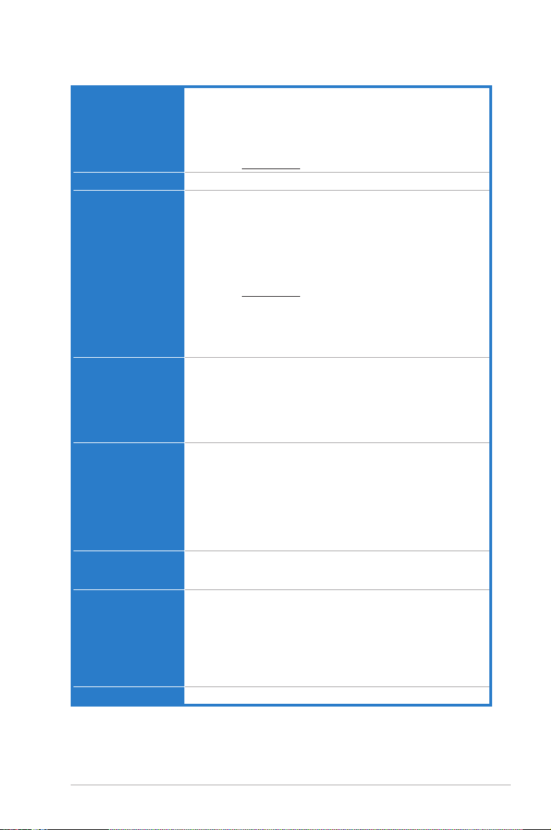
P8H77-V specications summary
CPU
Chipset
Memory
Expansion slots
VGA
Multi-GPU support
Storage
LAN
LGA1155 socket for Intel® 3rd/2nd Generation Core™ i7 / Core™ i5 /Core™ i5 /
Core™ i3 / Pentium® / Celeron® Processors
Supports 22/32nm CPU
Supports Intel® Turbo Boost Technology 2.0
* The Intel® Turbo Boost Technology 2.0 support depends on the CPU
types.
** Refer to www.asus.com for Intel CPU support list
Intel® H77 Express Chipset
4 x DIMMs, max. 32GB, DDR3 2200(O.C.)/2133(O.C.)/2000(O.C.)/
1866(O.C.)/1600/1333/1066 MHz, non-ECC, un-buffered memory
Dual channel memory architecture
Supports Intel® Extreme Memory Prole (XMP)
* DDR3 1600 MHz and higher memory frequency is supported by Intel®
3rd generation processors.
** Due to the CPU behavior, DDR3 2133/1866 MHz memory module will
run at DDR3 2000/1800 MHz frequency as default.
*** Refer to www.asus.com for the latest Memory QVL (Qualied Vendors
List).
**** When you install a total memory of 4GB capacity or more,
Windows® 32-bit operating system may only recognize less than
3GB. We recommend a maximum of 3GB system memory if you
are using a Windows® 32-bit operating system.
1 x PCI Express 3.0* x16 slot [blue] (at x16 mode)
1 x PCI Express 2.0 x16 slots [black] (at x4 mode, compatible with
PCIe x1 and x4 devices)
2 x PCI Express 2.0 x1 slots
3 x PCI slots
* PCIe 3.0 speed is supported by Intel® 3rd generation Core™
processors.
Integrated graphics processor — Intel® HD Graphics support
Multi-VGA output support: HDMI, DisplayPort, DVI-D, RGB ports
Supports HDMI with max. resolution of 1920 x 1200 @60Hz
Supports DisplayPort 1.1a with max. resolution of 2560 x 1600 @60Hz
Supports DVI with max. resolution of 1920 x 1200 @60Hz
Supports RGB with max. resolution of 2048 x 1536 @75Hz
Supports Intel® InTru™ 3D/Quick Sync Video/Clear Video HD
Technology/Insider™
Maximum shared memory of 1696 MB
Supports ATI® Quad-GPU CrossFireX™ Technology
Supports Lucidlogix® Virtu MVP™ Technology*
* LucidLogix® Virtu MVP™ supports Windows® 7 operating systems.
Intel® H77 Express Chipset
— 2 x SATA 6.0 Gb/s ports (gray) with RAID 0, 1, 5, 10 support
— 4 x SATA 3.0 Gb/s ports (blue) with RAID 0, 1, 5, 10 support
— Intel® Rapid Storage Technology supports RAID 0, 1, 5, and 10
— Supports Intel® Smart Response Technology, Intel® Rapid Start
Technology, Intel® Smart Connect Technology*
* Supports on Intel® Core™ processor family with Windows® 7
operating systems.
Qualcomm Atheros® 8161 PCIe Gigabit LAN controller
(continued on the next page)
ix

P8H77-V specications summary
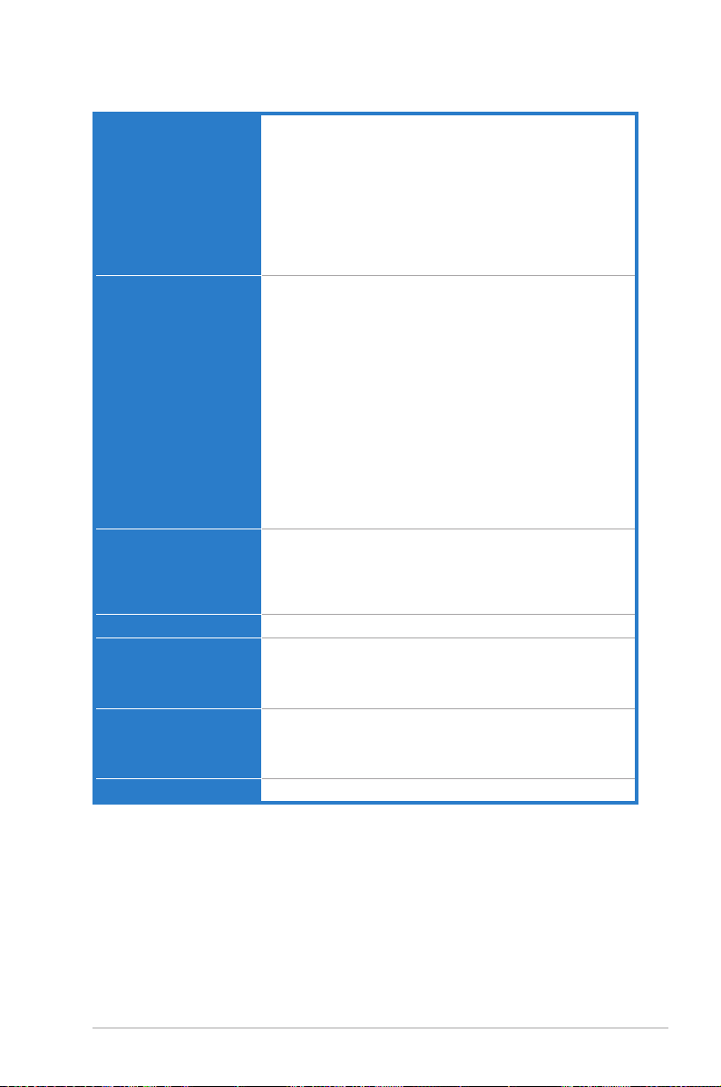
Audio
USB
ASUS unique features
ASUS exclusive
overclocking features
VIA® VT1708S 8-channel high denition audio CODEC
— Supports jack-detection, multi-streaming and front panel
jack-retasking
— Optical S/PDIF out port at back I/O
Intel® H77 Express Chipset — supports ASUS USB 3.0 Boost Turbo
Mode and UASP Mode*
— 2 x USB 3.0/2.0 ports at mid-board for front panel support
— 2 x USB 3.0/2.0 ports at back panel (blue)
Intel® H77 Express Chipset
— 10 x USB 2.0/1.1 ports (6 ports at mid-board, 4 ports at back
panel)
* The USB 3.0 ports only support Windows® 7 or later versions.
UASP standard only supports Windows® 8.
ASUS DIGI+ VRM
— ASUS DIGI+ VRM: Digital Power Design for the CPU and iGPU
— ASUS 6+1+2 Phase Power Design
ASUS Protect 3.0
— EPU
— ASUS Anti-Surge Protection
— Low EMI
— ESD
— 100% All high quality conductive polymer capacitors
ASUS Exclusive Features:
— ASUS AI Suite II
— TurboV
— GPU Boost
— MemOK!
— ASUS UEFI BIOS EZ Mode featuring graphics user interface
— USB 3.0 Boost featuring the latest USB 3.0 UASP standard
ASUS Quiet Thermal Solution:
— ASUS Fanless Design: Stylish heatsink solution and MOS heatsink
— ASUS Fan Xpert
ASUS EZ DIY:
— ASUS CrashFree BIOS 3
— ASUS EZ Flash 2 ASUS EZ Flash 2
— ASUS MyLogo 2™
ASUS Q-Design:
— ASUS Q-Slot
Precision Tweaker 2:
— vCore: Adjustable CPU voltage at 0.005V increment
— vCCSA: 191-step system agent voltage control
— vDRAM Bus: 191-step Memory voltage control
— vPCH: 191-step Chipset voltage control
— iGPU: 127-step iGPU voltage control
— vCPU_PLL: 1-step CPU & PCH PLL voltage control
SFS (Stepless Frequency Selection):
— BCLK/PCIE frequency tuning from 80MHz up to 300MHz at 1MHz
increment
Overclocking Protection:
— ASUS C.P.R.(CPU Parameter Recall)
(continued on the next page)
x
P8H77-V specications summary
Back panel I/O ports 1 x PS/2 keyboard / mouse combo port
Internal I/O connectors 1 x USB 3.0/2.0 connector supports additional 2 USB ports (19-pin)
BIOS features 64 Mb Flash ROM, UEFI AMI BIOS, PnP, DMI 2.0, WfM 2.0, SM
Manageability WfM 2.0, DMI 2.0, WOL by PME, WOR by PME, PXE
Accessories 2 x Serial ATA 6.0Gb/s cables
Support DVD contents Drivers
Form factor ATX form factor: 12 in. x 8.9 in. (30.5 cm x 22.6 cm)
1 x Optical S/PDIF output port
1 x HDMI port
1 x DVI-D port
1 x D-Sub port
1 x DisplayPort
1 x LAN (RJ-45) port
4 x USB 2.0/1.1 ports
2 x USB 3.0/2.0 ports
6-Jack 8-channel audio I/O ports
3 x USB 2.0/1.1 connectors support additional 6 USB ports
2 x SATA 6.0 Gb/s connectors (gray)
4 x SATA 3.0 Gb/s connectors (blue)
1 x CPU fan connector (4-pin)
2 x Chassis fan connectors (4-pin)
1 x Power fan connector (3-pin)
1 x Front panel audio connector (AAFP)
1 x COM connector
1 x S/PDIF output connector
1 x 24-pin EATX power connector
1 x 8-pin EATX 12V power connector
1 x System panel connector
1 x GPU Boost switch
1 x MemOK! button
1 x Clear CMOS jumper
BIOS 2.6, ACPI 2.0a, Multi-language BIOS, ASUS EZ Flash 2,
ASUS CrashFree BIOS 3, F12 PrintScreen Function, F3 Shortcut
function, and ASUS DRAM SPD (Serial Presence Detect)
memory information
1 x I/O shield
1 x User Manual
1 x Support DVD
ASUS Utilities
ASUS Update
Anti-virus software (OEM version)
*Specications are subject to change without notice.
xi

xii
Chapter 1
Chapter 1: Product introduction
1.1 Welcome!
Thank you for buying an ASUS® P8H77-V motherboard!
The motherboard delivers a host of new features and latest technologies, making it another
standout in the long line of ASUS quality motherboards!
Before you start installing the motherboard, and hardware devices on it, check the items in
your package with the list below.
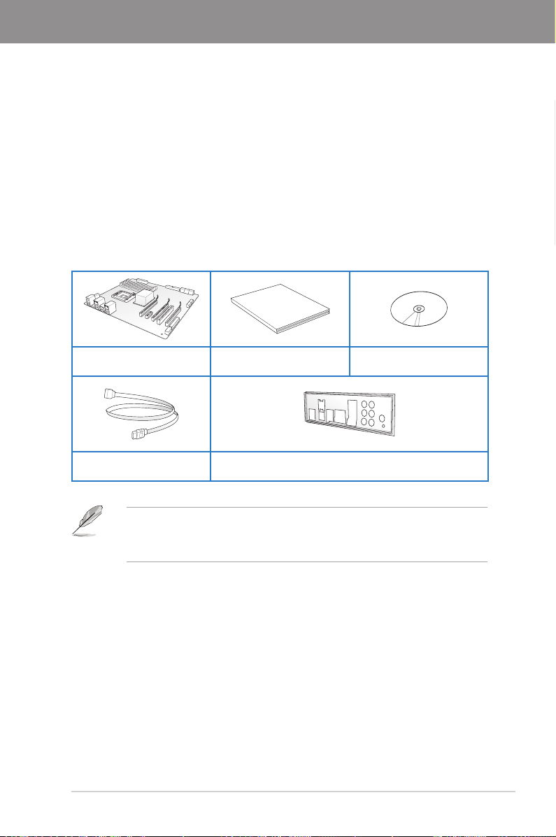
1.2 Package contents
Check your motherboard package for the following items.
ASUS P8H77-V motherboard User manual Support DVD
Chapter 1
2 x Serial ATA 6.0 Gb/s cables 1 x I/O shield
ASUS P8H77-V
• If any of the above items is damaged or missing, contact your retailer.
• The illustrated items above are for reference only. Actual product specications may
vary with different models.
1-1

1.3 Special features
1.3.1 Product highlights
Chapter 1
LGA1155 socket for Intel® 3rd/2nd Generation Core™ i7 / Core™ i5 /
Core™ i3 / Pentium® / Celeron® Processors
This motherboard supports the Intel® 3rd/2nd generation Core™ i7/i5/i3/Pentium®/Celeron®
processors in the LGA1155 package, with iGPU, memory, and PCI Express controllers
integrated to support onboard graphics out with dedicated chipsets, 2-channel (4 DIMMs)
DDR3 memory, and 16 PCI Express 3.0/2.0 lanes. This provides great graphics performance.
Intel® 3rd/2nd generation Core™ i7/i5/i3/Pentium®/Celeron® processors are among the most
powerful and energy efcient CPUs in the world.
Intel® H77 Express Chipset
The Intel® H77 Express Chipset is a single-chipset designed to support the 1155 socket
Intel® 3rd/2nd generation Core™ i7/i5/ i3/Pentium®/Celeron® processors. It provides improved
performance by utilizing serial point-to-point links, allowing increased bandwidth and stability.
Additionally, H77 chipset provides 4 USB 3.0 ports for 10 times faster data retrieval speed.
Moreover, IntelIntel® H77 Express Chipset can also enable iGPU function, letting users enjoy the
latest Intel® integrated graphic performance.
PCI Express® 3.0
PCI Express® 3.0 (PCIe 3.0) is the latest PCI Express bus standard with improved encoding
schemes that provide twice the performance of the current PCIe 2.0. The total bandwidth
for a x16 link reaches a maximum of 32Gb/s, double the 16 Gb/s of PCIe 2.0 (in x16 mode).
As such, PCIe 3.0 provides userss an unprecendented data speeds, combined with the
convenience and seamless transition offerred by complete backward compatibility with PCIe
1.0 and PCIe 2.0 devices. PCIe 3.0 will become a must-have feature for users who wish to
improve and optimize graphic performance, as well as have the latest technology available to
them.
* PCI 3.0 speed is supported by Intel® 3rd generation Core™ processors.
Intel® Smart Response Technology
SSD Speed with HDD Capacity
Intel® Smart Response Technology boosts overall system performance by using an installed
fast SSD (min 18.6GB available capacity required) as a cache for frequently accessed data.
Key benets include reduced load and wait times, and lower power consumption through the
elimination of unnecessary hard drive spin. This technology combines SSD performance with
hard drive capacity, operating up to 6X faster than a hard drive-only system.
* Intel® Smart Response Technology is supported by 3rd/2nd generation Intel® Core™ processor
family on Windows® 7™ operating systems.
** Operating systems must be installed on the HDD to launch Intel® Smart Response Technology.
The capacity of the SSD is reserved for caching function.
Intel® Smart Connect Technology
Your computer could receive web updates with fresh content for selected applications, even
when setting the system to sleep. This means less time waiting for applications to start,
update and sync with the cloud, providing a more efcient way.
1-2
Chapter 1: Product Introduction

Intel® Rapid Start Technology
Allows your computer to quickly resume from a lowe-power hibernate state in seconds.
Saving system memory to the designed SSD, provides your computer a faster wake-up
response time, while keeping the energy use low.
Quad-GPU CrossFireX™ Support
The motherboard’s powerful Intel® H77 platform optimizes PCIe allocation in multiple-GPU
congurations of CrossFireX™. This allows you to enjoy a never before-experienced brand
new gaming style.
Dual-Channel DDR3 2200(O.C.) / 2133(O.C.) / 2000(O.C.) / 1866(O.C.) /
1600 / 1333 / 1066 MHz Support
The motherboard supports DDR3 memory that features data transfer rates of DDR3
2200(O.C.) / 2133(O.C.) / 2000(O.C.) / 1866(O.C.) / 1600 / 1333 / 1066 MHz to meet
the higher bandwidth requirements of the latest 3D graphics, multimedia, and Internet
applications. The dual-channel DDR3 architecture enlarges the bandwidth of your system
memory to boost system performance.
Complete USB 3.0 Integration
Double USB Access, Double Convenience
ASUS facilitates the strategic USB 3.0 accessibility for both the front and rear panel – 4 USB
3.0 ports in total. Experience the latest plug & play connectivity at speeds up to 10 times
faster than USB 2.0. The P8H77-V affords greater convenience to high speed connectivity.
SATA 6.0 Gb/s Support
The Intel® H77 Express Chipset natively supports the next-generation Serial ATA (SATA)
interface, delivering up to 6.0 Gb/s data transfer. ASUS provides SATA 6.0 Gb/s ports with
enhanced scalability, faster data retrieval, and double the bandwidth of current bus systems.
S/PDIF out connector at the back I/O
This motherboard provides convenient connectivity to external home theater audio systems
via the optical S/PDIF (SONY-PHILIPS Digital Interface) out connecor at the back I/O. The
S/PDIF transfers digital audio without converting it to analog format and keeps the best signal
quality.
100% All High-quality Conductive Polymer Capacitors
This motherboard uses all high-quality conductive polymer capacitors for durability, improved
lifespan, and enhanced thermal capacity.
Chapter 1
1.3.2 ASUS Exclusive Features
ASUS DIGI+ VRM
Digital Power Control: Digital Power Design for the CPU and iGPU
All-new digital CPU power controls work perfectly together to match digital power signal
(SVID) requests from the CPU, with ultra-fast sensing and response efciently delivering
precision power. Accurate delivery reduces waste, and provides more stable CPU Vcore
voltages. Users can adjust CPU and its processor graphics (iGPU) voltages for various
overclocking scenarios, with accurate input through UEFI BIOS tuning or the exclusive ASUS
interface. This proprietary design increases overclocking headroom to push performance to
its full potential.
ASUS P8H77-V
1-3

EPU
Energy Efciency All Around
Tap into the world’s rst real-time PC power saving chip through the AI Suite II utility. Get
Chapter 1
total system-wide energy optimization by automatically detecting current PC loadings and
intelligently moderating power consumption. This also reduces fan noise and extends
component longevity.
GPU Boost
Go to the Limit with iGPU Level Up!
GPU Boost accelerates the integrated GPU for extreme graphics performance. The user-
friendly interface facilitates exible frequency adjustments. It easily delivers stable system-
level upgrades for every use.
MemOK!
Any Memory is A-OK!
MemOK! quickly ensures memory boot compatibility. This remarkable memory rescue tool
requires a mere push of a button to patch memory issues. MemOK! determines fail-safe
settings and dramatically improves your system boot success. Get your system up and
running in no time!
USB 3.0 Boost
Faster USB 3.0 Transmission with UASP
New ASUS USB 3.0 Boost technology supports UASP (USB Attached SCSI Protocol), the
latest USB 3.0 standard. With USB 3.0 Boost technology, a USB device’s transmission speed
is signicantly increased up to 170%, adding to an already impressive fast USB 3.0 transfer
speed. ASUS software automatically accelerates data speeds for compatible USB 3.0
peripherals without the need for any user interaction.
AI Suite II
One-stop Access to Innovative ASUS Features
With its user-friendly interface, ASUS AI Suite II consolidates all the exclusive ASUS features
into one simple to use software package. It allows you to supervise overclocking, energy
management, fan speed control, and voltage and sensor readings. This all-in-one software
offers diverse and ease to use functions, with no need to switch back and forth between
different utilities.
ASUS TurboV
Feel the adrenaline rush of real-time OC-now a reality with the ASUS TurboV. This easy OC
tool allows you to overclock without exiting or rebooting the OS; and its user-friendly interface
makes overclock with just a few clicks away. Moreover, the ASUS OC proles in TurboV
provides the best O.C. settings in different scenarios.
ASUS Anti-Surge Protection
This special design prevents expensive devices and the motherboard from damage caused
by power surges from switching power supply (PSU).
1-4
Chapter 1: Product Introduction

1.3.3 ASUS Quiet Thermal Solution
Fanless Design: stylish heatsink solution
The stylish heatsink features a 0-dB thermal solution that offers users a noiseless PC
environment. Not only the beautiful shape upgrades the visual enjoyment for motherboard
users, but also the heatsink design lowers the temperature of the chipset and power phase
area through high efcient heat-exchange. Combined with usability and aesthetics, the ASUS
stylish heatsink will give users an extremely silent and cooling experience with the elegant
appearance!
ASUS Fan Xpert
ASUS Fan Xpert intelligently allows you to adjust the CPU fan and chassis fan speeds
according to different ambient temperatures caused by different climate conditions in different
geographic regions and your PC’s loading. The built-in variety of useful proles offer exible
controls of fan speed to achieve a quiet and cool environment.
1.3.4 ASUS EZ DIY
ASUS UEFI BIOS
Flexible and Easy BIOS Interface
ASUS UEFI BIOS offers the rst mouse-controlled graphical BIOS designed with selectable
modes, providing a user-friendly interface that goes beyond the traditional keyboard-only
controls. It also natively supports fully-utilized hard drives larger than 2.2TB in 64-bit
operating systems.
ASUS exclusive interface
EZ Mode displays frequently-accessed info. Users can choose system performance settings,
and drag and drop boot priorities. Advanced Mode for performance enthusiasts includes
detailed DRAM settings via a dedicated memory info page for complete insight.
New upgrade! Quick and easy information for enhanced system control
— F12 BIOS snapshot hotkey for sharing UEFI information and troubleshooting
— New F3 Shortcut for most accessed information
— ASUS DRAM SPD (Serial Presence Detect) information for accessing memory
information, detecting faulty DIMMs, and helping with difcult POST situations.
Chapter 1
ASUS MyLogo2™
This feature allows you to convert your favorite photo into a 256-color boot logo for a more
colorful and vivid image on your screen.
ASUS CrashFree BIOS 3
ASUS CrashFree BIOS 3 is an auto-recovery tool that allows you to restore a corrupted BIOS
le using the bundled support DVD or USB ash disk that contains the latest BIOS le.
ASUS EZ-Flash 2
ASUS EZ Flash 2 is a user-friendly utility that allows you to update the BIOS without using a
bootable oppy disk or an OS-based utility.
ASUS P8H77-V
1-5

ASUS Q-Slot
ASUS Q-Slot is designed to speed up and simplify the DIY process to enhance your DIY
experience.
Chapter 1
1.3.5 Other special features
LucidLogix Virtu MVP
LucidLogix Virtu MVP featuring HyperFormance™ Technology boosts your PCIe graphics
card up to 60% beyond its original performance. Designed for Intel
Windows® 7 PCs, it perfectly combines the performance of discrete graphic cards with fast
computing iGPU. Also, with newly designed Virtual Sync, users can enjoy a smoother gaming
experience by eliminating tearing artifacts. LucidLogix Virtu MVP can also dynamically
assigns tasks to the best available graphics resource, based on power, performance, and
system load. This allows users to fully utilize 3x faster video conversion with Intel
Sync Video technology while retaining high-end 3D rendering and gaming performance,
provided by both NVIDIA and AMD graphic cards. When the PCIe graphic cards are not
required, the graphics control switches to the Intel® processor graphics, reducing the PCIe
graphics power use down to zero, making the system more environment-friendly. For users
searching for perfection, LucidLogix Virtu MVP provides great graphical performance, and
best quality and efciency.
* LucidLogix Virtu MVP supports Windows
** Intel® Quick Sync Video feature is supported by 3rd/2nd generation Intel® Core™ processor
family.
DisplayPort 1.1a Support
DisplayPort is a digital display interface standard that delivers up to 10.8 Gbps of bandwidth
over standard cables, providing billions of colors and bi-directional communications, thus
enabling the fastest refresh rates, and the highest resolution digital display through a single
cable. Also, it supports HDCP copy protection for Blu-ray discs. Simply output 3D signals
through the connected DisplayPort 1.1a cable with your 3D display, then you can sit back and
enjoy a perfect 3D animation experience.
®
7 operating system.
®
processor graphics and
®
Quick
HDMI Support
Enjoy Full HD 1080p Multimedia Home-Theater Entertainment
High Denition Multimedia Surface (HDMI) is a set of digital video standards that delivers
mulit-channel audio and uncompressed digital video for full HD 1080p visuals through a
single cable. Supporting HDCP copy protection such as HD DVD and blu-ray discs, HDMI
provides you with the highest quality home theater experience.
ErP Ready
The motherboard is European Union’s Energy-related Products (ErP) ready, and ErP requires
products to meet certain energy efciency requirement in regards to energy consumptions.
This is in line with ASUS vision of creating environment-friendly and energy-efcient products
through product design and innovation to reduce carbon footprint of the product and thus
mitigate environmental impacts.
1-6
Chapter 1: Product Introduction

Chapter 2
Chapter 2: Hardware information
2.1 Before you proceed
Take note of the following precautions before you install motherboard components or change
any motherboard settings.
• Unplug the power cord from the wall socket before touching any component.
• Before handling components, use a grounded wrist strap or touch a safely grounded
object or a metal object, such as the power supply case, to avoid damaging them due
to static electricity.
• Hold components by the edges to avoid touching the ICs on them.
• Whenever you uninstall any component, place it on a grounded antistatic pad or in the
bag that came with the component.
• Before you install or remove any component, ensure that the ATX power supply is
switched off or the power cord is detached from the power supply. Failure to do so
may cause severe damage to the motherboard, peripherals, or components.
ASUS P8H77-V
2-1
2.2 Motherboard overview
P8H77-V
PCIEX16_1
PCIEX16_2
PCIEX1_2
PCIEX1_1
PCI1
PCI2
PCI3
USB56USB78USB910
USB3_34
PANEL
SPDIF_OUT
CHA_FAN1
CHA_FAN2
CPU_FAN
Lithium Cell
CMOS Power
Super
I/O
VIA
VT1708S
DIGI
+VRM
AR
8161
COM1
64Mb
BIOS
SB_PWR
CLRTC
22.6cm(8.9in)
30.5cm(12.0in)
Intel
®
H77
DDR3 DIMM_A1 (64bit, 240-pin module)
DDR3 DIMM_A2 (64bit, 240-pin module)
DDR3 DIMM_B1 (64bit, 240-pin module)
DDR3 DIMM_B2 (64bit, 240-pin module)
USB3_12
ASM
1083
SATA3G_3 SATA3G_2 SATA3G_1
SATA6G_2SATA3G_4 SATA6G_1
MemOK!
DRAM_LED
EATXPWR
LGA1155
AUDIO
KB_USB3_34
LAN1_USB12
SPDIF_O
_HDMI
_DP
DVI_VGA
AAFP
PWR_FAN
EATX12V
GPU_Boost
GPU_LED
1 2 613 4
1
7
2
11
10
1718 16 15 14 13
9
5
8
12
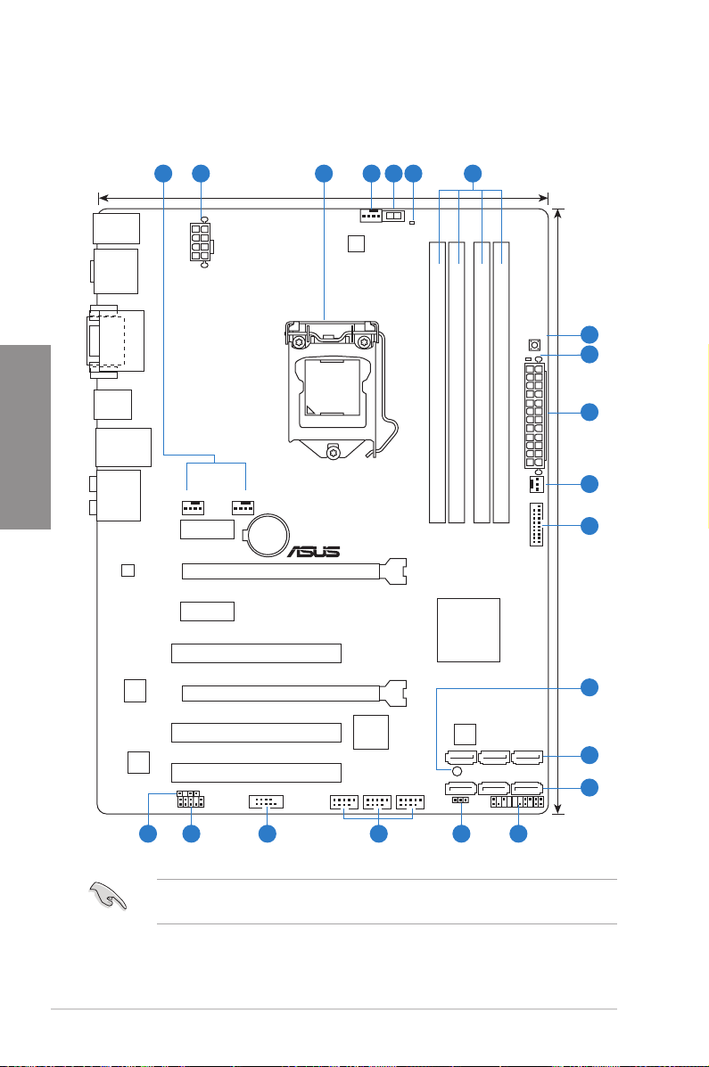
2.2.1 Motherboard layout
Chapter 2
Refer to
2.2.8 Internal connectors
information about rear panel connectors and internal connectors.
and
2.3.10 Rear panel connection
for more
2-2
Chapter 2: Hardware information
Layout contents
Connectors/Jumpers/Slots Page
1. CPU, chassis, and power fan connectors (4-pin CPU_FAN,
4-pin CHA_FAN1/2, 3-pin PWR_FAN)
2. ATX power connectors (24-pin EATXPWR, 8-pin EATX12V) 2-25
3. Intel® LGA1155 CPU socket 2-4
4. GPU Boost switch 2-17
5. GPU Boost LED 2-18
6. DDR3 DIMM slots 2-5
7. MemOK! switch 2-16
8. DRAM LED (DRAM_LED) 2-18
9. USB 3.0 connector (20-1 pin USB3_34) 2-21
10. Onboard LED (SB_PWR) 2-17
11. Intel® H77 Serial ATA 3.0Gb/s connectors
(7-pin SATA3G_1~4 [blue])
12. Intel® H77 Serial ATA 6.0Gb/s connectors
(7-pin SATA6G_1/2 [gray])
13. System panel connector (20-8 pin PANEL) 2-26
14. Clear RTC RAM (3-pin CLRTC) 2-15
15. USB 2.0 connectors (10-1 pin USB56, USB78, USB910) 2-21
16. Serial port connector (10-1 pin COM1) 2-22
17. Front panel audio connector (10-1 pin AAFP) 2-24
18. Digital audio connector (4-1 pin SPDIF_OUT) 2-22
2-23
2-20
2-19
Chapter 2
ASUS P8H77-V
2-3
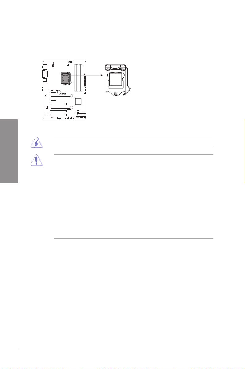
2.2.2 Central Processing Unit (CPU)
P8H77-V
P8H77-V CPU socket LGA1155
The motherboard comes with a surface mount LGA1155 socket designed for the Intel®
3rd/2nd Generation Core™ i7 / Core™ i5 / Core™ i3 / Pentium / Celeron Processors.
Chapter 2
Ensure that all power cables are unplugged before installing the CPU.
• The LGA1156 CPU is incompatible with the LGA1155 socket. DO NOT install a
LGA1156 CPU on the LGA1155 socket.
• Upon purchase of the motherboard, ensure that the PnP cap is on the socket and
the socket contacts are not bent. Contact your retailer immediately if the PnP cap
is missing, or if you see any damage to the PnP cap/socket contacts/motherboard
components. ASUS will shoulder the cost of repair only if the damage is shipment/
transit-related.
• Keep the cap after installing the motherboard. ASUS will process Return Merchandise
Authorization (RMA) requests only if the motherboard comes with the cap on the
LGA1155 socket.
• The product warranty does not cover damage to the socket contacts resulting from
incorrect CPU installation/removal, or misplacement/loss/incorrect removal of the PnP
cap.
2-4
Chapter 2: Hardware information
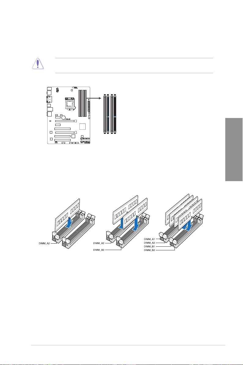
2.2.3 System memory
P8H77-V
P8H77-V 240-pin DDR3 DIMM sockets
DIMM_A1
DIMM_A2
DIMM_B1
DIMM_B2
The motherboard comes with four Double Data Rate 3 (DDR3) Dual Inline Memory Modules
(DIMM) slots.
A DDR3 module is notched differently from a DDR or DDR2 module. DO NOT install a DDR
or DDR2 memory module to the DDR3 slot.
Recommended memory congurations
Chapter 2
ASUS P8H77-V
2-5
Memory congurations
You may install 1GB, 2GB, 4GB and 8GB unbuffered and non-ECC DDR3 DIMMs into the
DIMM sockets.
Chapter 2
• You may install varying memory sizes in Channel A and Channel B. The system maps
the total size of the lower-sized channel for the dual-channel conguration. Any excess
memory from the higher-sized channel is then mapped for single-channel operation.
• According to Intel CPU spec, DIMM voltage below 1.65V is recommended to protect
the CPU.
• Always install DIMMs with the same CAS latency. For optimum compatibility, we
recommend that you obtain memory modules from the same vendor.
• Due to the memory address limitation on 32-bit Windows OS, when you install 4GB
or more memory on the motherboard, the actual usable memory for the OS can be
about 3GB or less. For effective use of memory, we recommend that you do any of the
following:
— Use a maximum of 3GB system memory if you are using a 32-bit Windows OS.
— Install a 64-bit Windows OS when you want to install 4GB or more on the
motherboard.
For more details, refer to the Microsoft® support site at
http://support.microsoft.com/kb/929605/en-us.
• This motherboard does not support DIMMs made up of 512Mb (64MB) chips or less
(Memory chip capacity counts in Megabit, 8 Megabit/Mb = 1 Megabyte/MB).
• The default memory operation frequency is dependent on its Serial Presence Detect
(SPD), which is the standard way of accessing information from a memory module.
Under the default state, some memory modules for overclocking may operate at a
lower frequency than the vendor-marked value. To operate at the vendor-marked
or at a higher frequency, refer to section
3.4 Ai Tweaker menu
for manual memory
frequency adjustment.
• For system stability, use a more efcient memory cooling system to support a full
memory load (4 DIMMs) or overclocking condition.
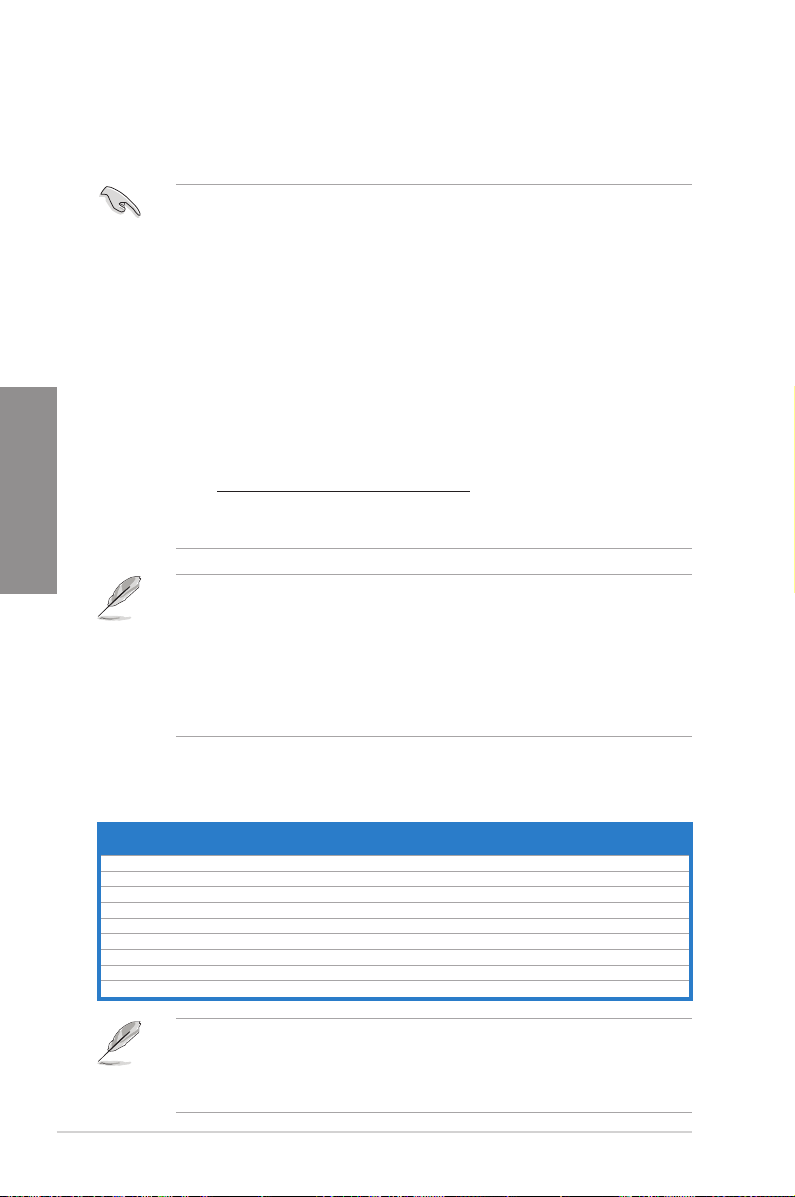
P8H77-V Motherboard Qualied Vendors Lists (QVL)
DDR3 2400 MHz (O.C.) capability
SS/DSChip
Vendors Part No. Size
Corsair CMGTX8(XMP) 8GB (2GBx 4) SS — — 10-12-10-27 1.65V • • •
G.SKILL F3-19200CL11Q-16GBZHD(XMP) 16GB(4GB x 4) DS — — 11-11-11-31 1.65V • •
G.SKILL F3-19200CL9D-4GBPIS(XMP) 4GB(2x 2GB) DS — — 9-11-9-28 1.65V • • •
GEIL GET34GB2400C9DC(XMP) 2GB DS — — 9-11-9-27 1.65V • • •
Kingmax FLLE88F-C8KKAA HAIS(XMP) 2GB SS — — 10-11-10-30 1.8V • • •
Transcend TX2400KLU-4GK(427652)(XMP) 4GB(2 x 2GB) SS — — — 1.65V • • •
Transcend TX2400KLU-4GK (381850)(XMP) 4GB(2x 2GB) SS — — 9 1.65V • • •
Transcend TX2400KLU-4GK(374243)(XMP) 4GB(2x 2GB) DS — — 9 1.65V • • •
PATRIOT PVV34G2400C9K(XMP) 4GB(2x 2GB) DS — — 9-11-9-27 1.65V • •
Brand
Chip
NO.
Timing Voltage
• DDR3 1600 MHz and higher memory frequency is supported by Intel® 3rd generation
processors.
• Due to the CPU behavior, DDR3 2133/1866 MHz memory module will run at DDR3
2000/1800 MHz frequency as default.
2-6
Chapter 2: Hardware information
DIMM socket support (Optional)
1 DIMM 2 DIMMs 4 DIMMs
P8H77-V Motherboard Qualied Vendors Lists (QVL)
DDR3 2250 MHz (O.C.) capability
Vendors Part No. Size SS/DS
Kingston KHX2250C9D3T1K2/4GX(XMP) 4GB(2 x 2GB) DS — — — 1.65V • • •
Chip
Chip NO. Timing Voltage
Brand
DIMM socket support
(Optional)
1 DIMM 2 DIMMs 4 DIMMs
P8H77-V Motherboard Qualied Vendors Lists (QVL)
DDR3 2200 MHz (O.C.) capability
Vendors Part No. Size SS/DS
GEIL GET34GB2200C9DC(XMP) 2GB DS — — 9-10-9-28 1.65V • • •
GEIL GET38GB2200C9ADC(XMP) 4GB DS — — 9-11-9-28 1.65V •
Kingmax FLKE85F-B8KJAA-FEIS(XMP) 2GB DS — — — — • • •
Kingmax FLKE85F-B8KHA EEIH(XMP) 4GB(2 x 2GB) DS — — — 1.5V-1.7V •
Kingmax FLKE85F-B8KJA FEIH(XMP) 4GB(2 x 2GB) DS — — — 1.5V-1.7V • • •
Chip
Chip NO. Timing Voltage
Brand
DIMM socket support
(Optional)
1 DIMM 2 DIMMs 4 DIMMs
P8H77-V Motherboard Qualied Vendors Lists (QVL)
DDR3 2133 MHz (O.C.) capability
Vendors Part No. Size
A-DATA AX3U2133GC2G9B-DG2(XMP) 2GB SS — — 9-11-9-27 1.55~1.75V • • •
Corsair CMT16GX3M4X2133C9(XMP 1.3) 16GB(4GB x 4) DS — — 9-11-10-27 1.50V • • •
Corsair CMT4GX3M2A2133C9(XMP) 4GB(2x 2GB) DS — — 9-10-9-24 1.65V • • •
Corsair CMT4GX3M2B2133C9(XMP) 4GB(2x 2GB) DS — — 9-10-9-27 1.50V • • •
G.SKILL F3-17000CL9Q-16GBZH(XMP) 16GB(4GB x 4) DS — — 9-11-10-28 1.65V • • •
GEIL GE34GB2133C9DC(XMP) 2GB DS — — 9-9-9-28 1.65V • •
GEIL GU34GB2133C9DC(XMP) 4GB(2 x 2GB) DS — — 9-9-9-28 1.65V • • •
Kingston KHX2133C9AD3T1K2/4GX(XMP) 4GB(2 x 2GB) DS — — — 1.65V • • •
Kingston KHX2133C9AD3X2K2/4GX(XMP) 4GB(2 x 2GB) DS — — 9-11-9-27 1.65V • • •
Kingston KHX2133C9AD3T1K4/8GX(XMP) 8GB(4 x 2GB) DS — — 9-11-9-27 1.65V • • •
Kingston KHX2133C9AD3T1FK4/8GX(XMP) 8GB(4x 2GB) DS — — — 1.65V • • •
SS/DSChip
Brand
Chip
Timing Voltage
NO.
DIMM socket support
(Optional)
1 DIMM 2 DIMMs 4 DIMMs
Chapter 2
P8H77-V Motherboard Qualied Vendors Lists (QVL)
DDR3 2000 MHz (O.C.) capability
Vendors Part No. Size
Apacer 78.AAGD5.9KD(XMP) 6GB(3 x 2GB) DS — — 9-9-9-27 1.65V • • •
Corsair CMZ4GX3M2A2000C10(XMP) 4GB(2 x 2GB) SS — — 10-10-10-27 1.50V • • •
Corsair CMT6GX3M3A2000C8(XMP) 6GB(3 x 2GB) DS — — 8-9-8-24 1.65V • • •
G.SKILL F3-16000CL9D-4GBFLS(XMP) 4GB(2 x 2GB) DS — — 9-9-9-24 1.65V • • •
G.SKILL F3-16000CL9D-4GBTD(XMP) 4GB(2 x 2GB) DS — — 9-9-9-27 1.65V • • •
G.SKILL F3-16000CL6T-6GBPIS(XMP) 6GB(3 x 2GB) DS — — 6-9-6-24 1.65V • • •
GEIL GUP34GB2000C9DC(XMP) 4GB(2 x 2GB) DS — — 9-9-9-28 1.65V • • •
Kingston KHX2000C9AD3T1K2/4GX(XMP) 4GB(2 x 2GB) DS — — — 1.65V • • •
Kingston KHX2000C9AD3W1K2/4GX(XMP) 4GB(2 x 2GB) DS — — — 1.65V • •
Kingston KHX2000C9AD3T1K2/4GX(XMP) 4GB(2 x 2GB) DS — — 9 1.65V • • •
Kingston KHX2000C9AD3W1K3/6GX(XMP) 6GB(3 x 2GB) DS — — — 1.65V • •
Kingston KHX2000C9AD3T1K3/6GX(XMP) 6GB(3 x 2GB) DS — — — 1.65V • •
Transcend TX2000KLN-8GK(XMP) 8GB(2 x 4GB) DS — — — 1.6V • • •
Asint SLA302G08-ML2HB(XMP) 4GB DS HYNIX H5TQ2G83BFR H9C — — • • •
SS/DSChip
Chip NO. Timing Voltage
Brand
ASUS P8H77-V
DIMM socket support
(Optional)
1 DIMM 2 DIMMs 4 DIMMs
2-7
P8H77-V Motherboard Qualied Vendors Lists (QVL)
DDR3 1866 MHz (O.C.) capability
Vendors Part No. Size SS/DS
Corsair CMT4GX3M2A1866C9(XMP) 4GB(2 x 2GB) DS — — 9-9-9-24 1.65V • • •
Corsair CMT6GX3MA1866C9(XMP) 6GB(3 x 2GB) DS — — 9-9-9-24 1.65V • •
Corsair CMZ8GX3M2A1866C9(XMP) 8GB(2 x 4GB) DS — — 9-10-9-27 1.50V • • •
F3-14900CL9Q-16GBZL(XMP)
G.SKILL
G.SKILL F3-14900CL10Q2-64GBZLD(XMP) 64GB(8GB x  DS — — 10-11-10-30 1.5V • • •
G.SKILL F3-14900CL9D-8GBXL(XMP) 8GB(2 x 4GB) DS — — 9-10-9-28 1.5V • • •
G.SKILL F3-14900CL9Q-8GBXL(XMP) 8GB(2GB x 4) DS — — 9-9-9-24 1.6V • • •
Kingston KHX1866C9D3T1K3/3GX(XMP) 3GB(3 x 1GB) SS — — — 1.65V • • •
Kingston KHX1866C9D3K4/16GX(XMP) 16GB(4GB x 4) DS — — — 1.65V • • •
KHX1866C9D3T1K3/6GX(XMP)
Kingston
Kingston KHX1866C11D3P1K2/8G 8GB(4GB x 2) DS — — — 1.5V • • •
16GB(4GB x 4) DS
6GB(3 x 2GB) DS
Chip
Chip NO. Timing Voltage
Brand
— 9-10-9-28
—
— —
1.5V •
1.65V •
—
P8H77-V Motherboard Qualied Vendors Lists (QVL)
DDR3 1600 MHz capability
Chapter 2
Vendors Part No. Size
A-DATA AM2U16BC2P1 2GB SS A-DATA 3CCD-1509A
A-DATA AX3U1600XB2G79-2X(XMP) 4GB(2 x 2GB) DS — — 7-9-7-21 1.55V-1.75V • • •
A-DATA AM2U16BC4P2 4GB DS A-DATA 3CCD-1509A
A-DATA AX3U1600GC4G9-2G(XMP) 8GB(2 x 4GB) DS — — 9-9-9-24 1.55V-1.75V • • •
A-DATA AX3U1600XC4G79-2X(XMP) 8GB(2 x 4GB) DS — — 7-9-7-21 1.55V-1.75V • • •
Corsair TR3X3G1600C8D(XMP) 3GB(3 x 1GB) SS — — 8-8-8-24 1.65V • • •
Corsair CMD12GX3M6A1600C8(XMP) 12GB(6 x 2GB) DS — — 8-8-8-24 1.65V • • •
Corsair CMP4GX3M2A1600C8(XMP) 4GB(2 x 2GB) DS — — 8-8-8-24 1.65V • • •
Corsair CMP4GX3M2A1600C9(XMP) 4GB(2 x 2GB) DS — — 9-9-9-24 1.65V • • •
Corsair CMP4GX3M2C1600C7(XMP) 4GB(2 x 2GB) DS — — 7-8-7-20 1.65V • • •
Corsair CMX4GX3M2A1600C9(XMP) 4GB(2 x 2GB) DS — — 9-9-9-24 1.65V • • •
Corsair CMX4GX3M2A1600C9(XMP) 4GB(2 x 2GB) DS — — 9-9-9-24 1.65V • • •
Corsair TR3X6G1600C8 G(XMP) 6GB(3 x 2GB) DS — — 8-8-8-24 1.65V • • •
Corsair TR3X6G1600C8D G(XMP) 6GB(3 x 2GB) DS — — 8-8-8-24 1.65V • • •
Corsair TR3X6G1600C9 G(XMP) 6GB(3 x 2GB) DS — — 9-9-9-24 1.65V • • •
Corsair CMP8GX3M2A1600C9(XMP) 8GB(2 x 4GB) DS — — 9-9-9-24 1.65V • • •
Corsair CMZ8GX3M2A1600C7R(XMP) 8GB(2 x 4GB) DS — — 7-8-7-20 1.50V • • •
Corsair CMX8GX3M4A1600C9(XMP) 8GB(4 x 2GB) DS — — 9-9-9-24 1.65V • • •
Crucial BL25664BN1608.16FF(XMP) 6GB(3 x 2GB) DS — — — — • • •
G.SKILL F3-12800CL9D-2GBNQ(XMP) 2GB(2 x 1GB) SS — — 9-9-9-24 1.5V • • •
G.SKILL F3-12800CL7D-4GBRH(XMP) 4GB(2 x 2GB) SS — — 7-7-7-24 1.6V • • •
G.SKILL F3-12800CL7D-4GBRM(XMP) 4GB(2 x 2GB) DS — — 7-8-7-24 1.6V • • •
G.SKILL F3-12800CL8D-4GBRM(XMP) 4GB(2 x 2GB) DS — — 8-8-8-24 1.60V • • •
G.SKILL F3-12800CL9D-4GBECO(XMP) 4GB(2 x 2GB) DS — — 9-9-9-24 XMP 1.35V • • •
G.SKILL F3-12800CL9D-4GBRL(XMP) 4GB(2 x 2GB) DS — — 9-9-9-24 1.5V • • •
G.SKILL F3-12800CL9T-6GBNQ(XMP) 6GB(3 x 2GB) DS — — 9-9-9-24 1.5V~1.6V • • •
G.SKILL F3-12800CL7D-8GBRH(XMP) 8GB(2 x 4GB) DS — — 7-8-7-24 1.6V • • •
G.SKILL F3-12800CL8D-8GBECO(XMP) 8GB(2 x 4GB) DS — — 8-8-8-24 XMP 1.35V • • •
G.SKILL F3-12800CL9D-8GBRL(XMP) 8GB(2 x 4GB) DS — — 9-9-9-24 1.5V • • •
GEIL GET316GB1600C9QC(XMP) 16GB(4 x 4GB) DS — — 9-9-9-28 1.6V • • •
GEIL GV34GB1600C8DC(XMP) 2GB DS — — 8-8-8-28 1.6V • • •
Kingmax FLGD45F-B8MF7 MAEH(XMP) 1GB SS — — 7 — • •
Kingmax FLGE85F-B8KJ9A FEIS(XMP) 2GB DS — — — — • • •
Kingmax FLGE85F-B8MF7 MEEH(XMP) 2GB DS — — 7 — • • •
Kingston KHX1600C9D3P1K2/4G 4GB(2 x 2GB) SS — — — 1.5V • • •
Kingston KHX1600C9D3K3/12GX(XMP) 12GB(3 x 4GB) DS — — 9-9-9-27 1.65V • • •
Kingston KHX1600C9D3T1BK3/12GX(XMP) 12GB(3 x 4GB) DS — — 9-9-9-27 1.65V • • •
Kingston KHX1600C9D3K4/16GX(XMP) 16GB(4 x 4GB) DS — — — 1.65V • • •
Kingston KHX1600C9AD3/2G 2GB DS — — — 1.65V • • •
Kingston KVR1600D3N11/2G-ES 2GB DS KTC D1288JPND
SS/DSChip
Chip NO. Timing Voltage
Brand
EL1126T
EL1126T
PLD9U
— — • • •
— — • • •
11-11-11-28 1.35V-1.5V • • •
DIMM socket support
(Optional)
1 DIMM 2 DIMMs 4 DIMMs
•
•
•
•
DIMM socket support
(Optional)
1 DIMM 2 DIMMs 4 DIMMs
2-8
Chapter 2: Hardware information
P8H77-V Motherboard Qualied Vendors Lists (QVL)
DDR3 1600 MHz capability (continued)
1.65V •
1.65V •
DIMM socket support
(Optional)
1 DIMM 2 DIMMs 4 DIMMs
•
• •
Vendors Part No. Size
Kingston KHX1600C7D3K2/4GX(XMP) 4GB(2 x 2GB) DS — — — 1.65V • • •
Kingston KHX1600C8D3K2/4GX(XMP) 4GB(2 x 2GB) DS — — 8 1.65V • • •
Kingston KHX1600C8D3T1K2/
4GX(XMP)
KHX1600C9D3K2/4GX(XMP)
Kingston
Kingston KHX1600C9D3LK2/
4GX(XMP)
Kingston KHX1600C9D3X2K2/
4GX(XMP)
Kingston KHX1600C9D3T1K3/
6GX(XMP)
Kingston KHX1600C9D3K3/6GX(XMP) 6GB(3 x 2GB) DS — — 9 1.65V • • •
Kingston KHX1600C9D3T1BK3/
6GX(XMP)
KHX1600C9D3K2/8GX(XMP)
Kingston
Kingston KHX1600C9D3P1K2/8G 8GB(2 x 4GB) DS — — — 1.5V • • •
Super
WA160UX6G9 6GB(3 x 2GB) DS — — 9 — •
Talent
Transcend JM1600KLN-8GK 8GB(2 x 4GB) DS Transcend TK483PCW3 — — • • •
Asint SLZ3128M8-EGJ1D(XMP) 2GB DS Asint 3128M8-GJ1D 9-9-9-24 1.6V • • •
Asint SLA302G08-EGG1C(XMP) 4GB DS Asint 302G08-GG1C — — • • •
SLA302G08-EGJ1C(XMP) 4GB DS Asint 302G08-GJ1C — — • • •
Asint
Elixir M2P2G64CB8HC9N-
DG(XMP)
Mushkin 998659(XMP) 6GB(3 x 2GB) DS — — 9-9-9-24 — • • •
Mushkin 998659(XMP) 6GB(3 x 2GB) DS — — 9-9-9-24 1.5~1.6V • • •
PATRIOT PGS34G1600LLKA 4GB(2 x 2GB) DS — — 7-7-7-20 1.7V • • •
SanMax SMD-4G68HP-16KZ 4GB DS HYNIX H5TQ2G83BFR
4GB(2 x 2GB) DS — — 8 1.65V • • •
4GB(2 x 2GB) DS
4GB(2 x 2GB) DS — — 9 XMP 1.35V • • •
4GB(2 x 2GB) DS — — 9-9-9-27 1.65V • • •
6GB(3x 2GB ) DS — — — 1.65V • • •
6GB(3 x 2GB) DS — — 9-9-9-27 1.65V • • •
8GB(2 x 4GB) DS
2GB DS — — — — • • •
SS/DSChip
Brand
— —
— —
Chip NO. Timing Voltage
9
9-9-9-27
PBC
— — • • •
P8H77-V Motherboard Qualied Vendors Lists (QVL)
DDR3 1333 MHz capability
(low voltage)
DIMM socket support
(Optional)
1 DIMM 2 DIMMs 4 DIMMs
• • •
Vendors Part No. Size
A-DATA AD31333001GOU 1GB SS A-Data AD30908C8D-151C E0906 — — • • •
A-DATA AD3U1333C2G9 2GB SS A-DATA 3CCD-1509HNA1126L — — • • •
A-DATA AD63I1B0823EV 2GB SS A-Data 3CCA-1509A — — • • •
A-DATA AM2U139C2P1 2GB SS ADATA 3CCD-1509A EL1127T — — • • •
A-DATA AX3U1333C2G9-BP 2GB SS — — — — • • •
A-DATA AD31333G001GOU 3GB(3 x 1GB) SS — — 8-8-8-24 1.65-1.85V •
A-DATA AXDU1333GC2G9-
2G(XMP)
A-DATA AD31333G002GMU 2GB DS — — 8-8-8-24 1.65-1.85V • •
A-DATA AD63I1C1624EV 4GB DS A-Data 3CCA-1509A — — • • •
A-DATA AM2U139C4P2 4GB DS ADATA 3CCD-1509A EL1127T — — • • •
A-DATA SU3U1333W8G9-B 8GB DS ELPIDA J4208BASE-DJ-F — — • • •
Apacer 78.A1GC6.9L1 2GB DS Apacer AM5D5808DEWSBG — — • • •
Apacer 78.A1GC6.9L1 2GB DS Apacer AM5D5808FEQSBG 9 — • • •
Apacer AU02GFA33C9NBGC 2GB DS Apacer AM5D5808
Apacer 78.B1GDE.9L10C 4GB DS Apacer AM5D5908
Corsair CM3X1024-1333C9 1GB SS — — 9-9-9-24 1.60V • • •
Corsair TR3X3G1333C9 G 3GB(3 x 1GB) SS — — 9-9-9-24 1.50V • • •
Corsair TR3X6G1333C9 G 6GB(3 x 2GB) SS — — 9-9-9-24 1.50V • •
Corsair CMD24GX3M6A
1333C9(XMP)
Corsair TW3X4G1333C9D G 4GB(2 x 2GB) DS — — 9-9-9-24 1.50V • • •
Corsair CM3X4GA1333C9N2 4GB DS Corsair 256MBDCJGELC0401136 9-9-9-24 — • • •
Corsair CMX4GX3M1A1333C9 4GB DS — — 9-9-9-24 1.50V • • •
4GB(2 x 2GB) SS — — 9-9-9-24 1.25V-1.35V
24GB(6 x 4GB) DS — — 9-9-9-24 1.60V • • •
SS/DSChip
Brand
Chip NO. Timing Voltage
APQSBG
CEHSBG
— — • • •
— — • • •
•
Chapter 2
ASUS P8H77-V
2-9

P8H77-V Motherboard Qualied Vendors Lists (QVL)
DDR3 1333 MHz capability (continued)
Vendors Part No. Size
Corsair CMD8GX3M4A1333C7 8GB(4 x 2GB) DS — — 7-7-7-20 1.60V • • •
Crucial CT12864BA1339.8FF 1GB SS Micron 9FF22D9KPT 9 — • • •
Crucial CT25664BA1339.16FF 2GB DS Micron 9KF27D9KPT 9 — • • •
Crucial BL25664BN1337.16FF(XMP)
ELPIDA EBJ10UE8EDF0-DJ-F 1GB SS ELPIDA J1108EDSE-DJ-F — 1.35V
ELPIDA EBJ21UE8EDF0-DJ-F 2GB DS ELPIDA J1108EDSE-DJ-F — 1.35V
G.SKILL F3-10600CL8D-
2GBHK(XMP)
G.SKILL F3-10600CL9D-2GBNQ 2GB(2 x 1GB) SS — — 9-9-9-24 1.5V • • •
G.SKILL F3-10666CL7T-3GBPK(XMP) 3GB(3 x 1GB) SS — — 7-7-7-18 1.5~1.6V • • •
G.SKILL F3-10666CL8D-
4GBECO(XMP)
G.SKILL F3-10666CL7T-6GBPK
Chapter 2
(XMP)
G.SKILL F3-10666CL7D-
8GBRH(XMP)
GEIL GV32GB1333C9DC 2GB(2 x 1GB) DS — — 9-9-9-24 1.5V • • •
GEIL GG34GB1333C9DC 4GB(2 x 2GB) DS GEIL GL1L128M88BA12N 9-9-9-24 1.3V
GEIL GV34GB1333C9DC 4GB(2 x 2GB) DS — — 9-9-9-24 1.5V • • •
GEIL GVP34GB1333C7DC 4GB(2 x 2GB) DS — — 7-7-7-24 1.5V • • •
Hynix HMT112U6TFR8A-H9 1GB SS Hynix H5TC1G83TFRH9A — 1.35V
Hynix HMT325U6BFR8C-H9 2GB SS Hynix H5TQ2G83BFRH9C — — • • •
Hynix HMT125U6TFR8A-H9 2GB DS Hynix H5TC1G83TFRH9A — 1.35V
Hynix HMT351U6BFR8C-H9 4GB DS Hynix H5TQ2G83BFRH9C — — • • •
Kingmax FLFD45F-B8KL9 NAES 1GB SS Kingmax KKB8FNWBFGNX-
Kingmax FLFE85F-C8KF9 CAES 2GB SS Kingmax KFC8FMFXF-DXX-
Kingmax FLFE85F-C8KL9 NAES 2GB SS Kingmax KFC8FNLXF-DXX-
Kingmax FLFE85F-C8KM9 NAES 2GB SS Kingmax KFC8FNMXF-BXX-
Kingmax FLFE85F-B8KL9 NEES 2GB DS Kingmax KKB8FNWBFGNX-
Kingmax FLFF65F-C8KL9 NEES 4GB DS Kingmax KFC8FNLXF-DXX-
Kingmax FLFF65F-C8KM9 NEES 4GB DS Kingmax KFC8FNMXF-BXX-
Kingston KVR1333D3N9/1G(low
prole)
Kingston KVR1333D3N9/2G
(low prole)
Kingston KVR1333D3S8N9/2G 2GB SS Micron IID77 D9LGK — 1.5V • • •
Kingston KVR1333D3S8N9/2G-SP
(low prole)
Kingston KVR1333D3N9/2G
(low prole)
Kingston KVR1333D3N9/2G 2GB DS KTC D1288JPNDPLD9U 9 1.5V • • •
Kingston KVR1333D3N9/2G 2GB DS ELPIDA J1108BDSE-DJ-F 9 1.5V • • •
Kingston KVR1333D3N9/2G-SP(low
prole)
Kingston KVR1333D3N9/2G-SP(low
prole)
Kingston KHX1333C7D3K2/4GX(XMP) 4GB(2 x 2GB) DS — — 7 1.65V • • •
Kingston KHX1333C9D3UK2/
4GX(XMP)
Kingston KVR1333D3N9/4G(low
prole)
Kingston KVR1333D3N9/4G(low
prole)
Kingston KVR1333D3N9/4G 4GB DS KTC D2568JENCNGD9U — 1.5V • • •
Kingston KVR1333D3N9/4G 4GB DS Hynix H5TQ2G83AFR — — • • •
6GB(3 x 2GB) DS
1GB SS G.SKILL — — — • • •
4GB(2 x 2GB) DS
6GB(3 x 2GB) DS — — 7-7-7-18 1.5~1.6V • •
8GB(2 x 4GB) DS — — 7-7-7-21 1.5V • • •
1GB SS ELPIDA J1108BDBG-DJ-F 9 1.5V • • •
2GB SS Hynix H5TQ2G83AFRH9C 9 — • •
2GB SS ELPIDA J2108BCSE-DJ-F — 1.5V • • •
2GB DS ELPIDA J1108BFBG-DJ-F 9 1.5V • • •
2GB DS KTC D1288JEMFNGD9U — 1.5V • • •
2GB DS Kingston D1288JPSFPGD9U — 1.5V • • •
4GB(2 x 2GB) DS — — 9 XMP 1.25V • • •
4GB DS ELPIDA J2108BCSE-DJ-F 9 1.5V • • •
4GB DS ELPIDA J2108BCSE-DJ-F — 1.5V • • •
SS/DSChip
Brand
—
—
Chip NO. Timing Voltage
— 7-7-7-24
— 8-8-8-24
27A
15A
15A
15A
26A
15A
15A
1.65V •
(low voltage)
(low voltage)
XMP 1.35V •
(low voltage)
(low voltage)
(low voltage)
— — • • •
— — • • •
— — • • •
— — • • •
— — • • •
— — • • •
— — • • •
DIMM socket support
(Optional)
1 DIMM 2 DIMMs 4 DIMMs
•
•
• • •
• •
•
•
• • •
• • •
• • •
2-10
Chapter 2: Hardware information
P8H77-V Motherboard Qualied Vendors Lists (QVL)
DDR3 1333 MHz capability (continued)
Vendors Part No. Size
Kingston KVR1333D3N9/4G-SP
Micron MT4JTF12864AZ-1G4D1 1GB SS Micron OJD12D9LGQ — — •
Micron MT8JTF12864AZ-1G4F1 1GB SS Micron 9FF22D9KPT 9 — • • •
Micron
Micron MT8JTF25664AZ-1G4M1 2GB SS MICRON IJM22 D9PFJ — — • • •
Micron MT16JTF25664AZ-1G4F1 2GB DS Micron 9KF27D9KPT 9 — • • •
Micron MT16JTF51264AZ-1G4D1 4GB DS Micron OLD22D9LGK — — • • •
NANYA NT4GC64B8HG0NF-CG 4GB DS NANYA NT5CB256M8GN-CG- — • • •
PSC AL7F8G73F-DJ2 1GB SS PSC A3P1GF3FGF — — • • •
PSC
SAMSUNG M378B2873FHS-CH9 1GB SS SAMSUNG K4B1G0846F — — • • •
SAMSUNG M378B5773DH0-CH9 2GB SS SAMSUNG K4B2G0846D — — • • •
SAMSUNG M378B5673FH0-CH9 2GB DS SAMSUNG K4B1G0846F — — • • •
SAMSUNG M378B5273CH0-CH9 4GB DS SAMSUNG K4B2G0846C — — • • •
SAMSUNG M378B1G73AH0-CH9 8GB DS SAMSUNG K4B4G0846A-HCH9 — — • •
Super Talent W1333UA1GH 1GB SS Hynix H5TQ1G83TFR 9 — • • •
Super Talent W1333UX2G8(XMP) 2GB(2x 1GB) SS — — 8 — • •
Super Talent W1333UB2GS 2GB DS SAMSUNG K4B1G0846F 9 — • • •
Super Talent W1333UB4GS 4GB DS SAMSUNG K4B2G0846C — — • • •
Super Talent W1333UX6GM 6GB(3x 2GB) DS Micron 0BF27D9KPT 9-9-9-24 1.5V • • •
Transcend JM1333KLN-2G 2GB SS Micron 0YD77D9LGK — — • • •
Transcend JM1333KLN-2G 2GB SS Hynix H5TQ2G83BZRH9C — — • • •
Transcend TS256MLK64V3U 2GB DS Micron 9GF27D9KPT — — • •
Century PC3-10600 DDR3-
Elixir M2F2G64CB88B7N-CG 2GB SS Elixir N2CB2G80BN-CG — — • •
Elixir M2F2G64CB88D7N-CG 2GB SS Elixir N2CB2G80DN-CG — — • •
Elixir M2F2G64CB88G7N-CG 2GB SS Elixir N2CB2G80GN-CG — — • • •
Elixir M2F4G64CB8HB5N-CG 4GB DS Elixir N2CB2G80BN-CG — — • • •
Elixir M2F4G64CB8HD5N-CG 4GB DS Elixir N2CB2G80DN-CG — — • •
KINGSHARE KSRPCD313332G 2GB DS PATRIOT PM128M8D385-15 — — • • •
KINGSTEK KSTD3PC-10600 2GB SS MICRON PE911-125E — — • • •
Kingtiger 2GB DIMM PC3-10666 2GB DS SAMSUNG SEC 904 HCH9
Kingtiger KTG2G1333PG3 2GB DS — — — — • • •
MARKVISION BMD32048M1333C9-1123 2GB DS MARKVISION M3D1288P-13 — — • • •
MARKVISION BMD34096M1333C9-1124 4GB DS MARKVISION M3D2568E-13 — — • • •
PATRIOT PSD31G13332H 1GB DS — — 9 — • •
PATRIOT PSD31G13332 1GB DS PATRIOT PM64M8D38U-15 — — • • •
PATRIOT PSD32G13332H 2GB DS — — — — • • •
PATRIOT PG38G1333EL(XMP) 8GB DS — — 9-9-9-24 1.5V • •
RAMAXEL RMR1870ED48E8F-1333 2GB DS ELPIDA J1108BDBG-DJ-F — — • • •
RAMAXEL RMR1870EC58E9F-1333 4GB DS ELPIDA J2108BCSE-DJ-F — — • • •
RiDATA E304459CB1AG32Cf 4GB DS RiDATA N/A 9 — • • •
SanMax SMD-4G68H1P-13HZ 4GB DS HYNIX H5TQ2G83BFR H9C — — • • •
SILICON
POWER
SILICON
POWER
SILICON
POWER
TAKEMS TMS1GB364D081-107EY 1GB SS — — 7-7-7-20 1.5V • •
TAKEMS TMS1GB364D081-138EY 1GB SS — — 8-8-8-24 1.5V • •
TAKEMS TMS2GB364D081-107EY 2GB DS — — 7-7-7-20 1.5V • •
TAKEMS TMS2GB364D081-138EY 2GB DS — — 8-8-8-24 1.5V • •
TAKEMS TMS2GB364D082-138EW 2GB DS — — 8-8-8-24 1.5V • •
UMAX E41302GP0-73BDB 2GB DS UMAX U2S24D30TP-13 — — • • •
WINTEC 3WVS31333-2G-CNR 2GB DS AMPO AM3420803-13H — — • • •
(low prole)
MT8JTF25664AZ-1G4D1
AL8F8G73F-DJ2
1333 9-9-9
SP001GBLTU133S01 1GB SS NANYA NT5CB128M8AN-CG9 — • • •
SP001GBLTU133S02 1GB SS Elixir N2CB1680AN-C6 9 — • • •
SP002GBLTU133S02 2GB DS Elixir N2CB1680AN-C6 9 — • • •
4GB DS Kingston D2568JENCPGD9U — 1.5V • • •
2GB SS
2GB DS
1GB SS NANYA NT5CB128M8DN-CF- — • • •
SS/
Chip Brand Chip NO. Timing Voltage
DS
Micron OJD12D9LGK
PSC A3P1GF3FGF
K4B1G0846D
—
—
— — • • •
DIMM socket support
(Optional)
1 DIMM 2 DIMMs 4 DIMMs
— •
— •
•
• •
•
Chapter 2
ASUS P8H77-V
2-11
P8H77-V Motherboard Qualied Vendors Lists (QVL)
DDR3 1066 MHz capability
Vendors Part No. Size
Crucial CT12864BA1067.8FF 1GB SS Micron 9GF22D9KPT 7 — • • •
Crucial CT25664BA1067.16FF 2GB DS Micron 9HF22D9KPT 7 — • • •
ELPIDA EBJ10UE8EDF0-AE-F 1GB SS ELPIDA J1108EDSE-DJ-F — 1.35V(low voltage) • • •
ELPIDA
Kingston KVR1066D3N7/1G(low
Kingston KVR1066D3N7/2G 2GB DS ELPIDA J1108BDSE-DJ-F 7 1.5V • • •
Kingston KVR1066D3N7/4G 4GB DS Hynix H5TQ2G83AFR 7 1.5V • • •
Micron MT8JTF12864AZ-1G1F1 1GB SS Micron 9GF22D9KPT 7 — • • •
Micron MT16JTF25664AZ-1G1F1 2GB DS Micron 9HF22D9KPT 7 — • • •
Kingtiger
Chapter 2
EBJ21UE8EDF0-AE-F
prole)
2GB DIMM PC3-8500
SS/DSChip
2GB DS
1GB SS ELPIDA J1108BFSE-DJ-F 7 1.5V • • •
2GB DS
Chip NO. Timing Voltage
Brand
ELPIDA J1108EDSE-DJ-F
Hynix H5TQ1G83AFP G7C
Side(s): SS — Single-sided DS — Double-sided
DIMM support:
• 1 DIMM:
•
Supports one (1) module inserted into any slot as Single-channel memory
conguration.
Supports two (2) modules inserted into either the blue slots or the black
2 DIMMs:
We suggest that you install the module into A2 slot.
slots as one pair of Dual-channel memory conguration.
you install the modules into slots A2 and B2 for better compatibility.
• 4 DIMMs:
Supports four (4) modules inserted into both the blue and black slots as
two pairs of Dual-channel memory conguration.
Visit the ASUS website for the latest QVL.
—
—
1.35V(low voltage) •
— •
DIMM socket support
(Optional)
1 DIMM 2 DIMMs 4 DIMMs
•
•
•
•
We suggest that
2-12
Chapter 2: Hardware information
Loading…
- Инструкции и руководства
- Бренды
- ASUS
- P8H77-V
- Справочник Пользователя
-
Page 1: Asus P8H77-V
Motherboard P8H77-V[…]
-
Page 2: Asus P8H77-V
ii G7024 Erste Ausgabe Juli 2012 Copyright © 2012 ASUST eK COMPUTER INC. A lle Rechte vorbehalten. Kein T eil dieses Handbuchs, einschließlich der darin beschriebenen Produkte und Software, darf ohne ausdrückliche, schriftliche Genehmigung von ASUST eK COMPUTER INC. (“ ASUS”) in irgendeiner F or m, ganz gleich auf welche Weise, vervielfälti[…]
-
Page 3: Asus P8H77-V
iii Inhalt Sicherheitsinformationen ……………………………………………………………………………………… vi Über dieses Handbuch………………………………………………………………………………………….. vii P8H77-V Spezikationsübersicht ………………………………………..[…]
-
Page 4: Asus P8H77-V
iv Inhalt Kapitel 3: BIOS-Setup 3.1 Kennenlernen des BIOS …………………………………………………………………………… 3-1 3.2 BIOS-Setupprogramm …………………………………………………………………………….. 3-1 3.2.1 EZ Mode ……………………………………………………………[…]
-
Page 5: Asus P8H77-V
v 4.3.6 F AN Xper t ……………………………………………………………………………………………………… 4-9 4.3.7 Probe II ………………………………………………………………………………………………………… 4-10 4.3.8 Sensor Recorder ………………………………………[…]
-
Page 6: Asus P8H77-V
vi Sicherheitsinforma tionen Elektrische Sicherheit • Um die Gefahr eines Stromschlags zu verhindern, ziehen Sie die Netzleitung aus der Steckdose, bevor Sie das System an einem ander en Or t aufstellen. • Beim Anschließen oder Trennen v on G eräten an das oder vom S ystem müssen die Netzleitungen der Geräte ausgesteckt sein, bevor die Sig […]
-
Page 7: Asus P8H77-V
vii Über dieses Handbuch Di es es B enu tz er ha nd buc h en th äl t di e In fo rm a tio ne n, d ie Si e be i de r In st al la t i on u nd K on gu ra ti on d es Mo th er boa r d s br au ch en . Die Gestaltung dieses Handbuchs Das Handbuch enthält die folgenden T eile: • Kapitel 1: Produkteinführung Dieses Kapitel beschreibt die Leistungsm[…]
-
Page 8: Asus P8H77-V
viii GEF AHR/W ARNUNG : Informationen zum V ermeiden von V erletzungen beim Ausführen einer A ufgabe. VORSICHT : Informationen zum Vermeiden von Schäden an den Komponenten beim Ausführ en einer Aufgabe . HINWEIS : Tipps und zusätzliche Informationen zur Erleichterung bei der Ausführung einer Auf gabe. WICHTIG : Anweisungen, die Sie beim A usf?[…]
-
Page 9: Asus P8H77-V
ix P8H77- V Sp ezikationsübersicht CPU Intel® Sockel LGA1155 für 3./2. Gen Intel® C ore™ i7 / Core™ i5 / C ore TM i3 / Pentium ® / C eleron ® -Pr ozessoren Unterstützt Intel® Turbo Boost- T echnologie 2.0 Unterstützt 22/32nm-CPU Unterstützt Intel ® Turbo Boost T echnology 2.0 * Die U nterstü tzung f ür In tel ® T urbo Boo st- T[…]
-
Page 10: Asus P8H77-V
x Audio VIA ® VT1708S 8-K anal HD-Audio- CODEC — Unterstützt Buchsenerkennung, Multi-Streaming und Frontblenden-Buchsenumprogrammierung — Optischer S/PDIF-Ausgang auf der Rücktafel USB Intel ® H77 Express Chipset — un terstüt zt ASUS USB 3.0 Boo st U ASP -Mod us* — 2 x USB 3.0/2.0-Anschlüsse auf Board-Mitte und Fr ontblende — 2 x U SB 3.0/2 .[…]
-
Page 11: Asus P8H77-V
xi P8H77- V Sp ezikationsübersicht * Die Spezikationen können ohne Vorankündigung geändert werden. Rücktafelanschlüsse 1 x PS/2- T astatur-/Mausanschluss PS/2- T astatur-/Mausanschluss 1 x Optischer S/PDIF-Ausgang Optischer S/PDIF-Ausgang 1 x HDMI-Anschluss -Anschluss 1 x DVI-D-Anschluss -Anschluss 1 x D-Sub-Anschluss -Anschluss 1 x Dis[…]
-
Page 12: Asus P8H77-V
xii[…]
-
Page 13: Asus P8H77-V
ASUS P8H77-V 1-1 Kapitel 1 1.1 W illkommen! Vielen Dank für den Kauf eines ASUS ® P8H77-V-Motherboards! P8H77-V-Motherboards! Motherboards! Eine Vielzahl von neuen Funktionen und neuest en T echnologien sind in dieses Motherboard integriert und machen es zu einem weiteren hervorragenden Produkt in der langen Reihe der ASUS Qualitätsmotherboards![…]
-
Page 14: Asus P8H77-V
1-2 Kapitel 1: Produkteinführung Kapitel 1 1.3 Sonder funktionen 1.3.1 Leistungsmerkmale des Produkts L GA1155-So ckel für Intel ® C ore™ i7 der 2. und 3. Generation / C ore™ i5 / Cor e™ i3- / P entium- / C eleron-Pr ozessoren Dieses Motherboard unterstützt die Intel ® 3./2. Generation Cor e™ i7/i5/i3/Pentium ® /Celeron ® -Pro zessor[…]
-
Page 15: Asus P8H77-V
ASUS P8H77-V 1-3 Kapitel 1 Intel ® Rapid Start- T echnologie Damit können Sie Ihren Computer aus dem Niedrigleistungs-Ruhemodus in wenigen Sekunden ganz schnell wieder auf T ouren bringen. Der Speicher wird zu der zugewiesenen SSD gespeicher t und ermöglicht Ihren Computer somit, die Arbeit in kürzester Zeit wieder aufzunehmen, w ährend der En[…]
-
Page 16: Asus P8H77-V
1-4 Kapitel 1: Produkteinführung Kapitel 1 EPU Energieezienz allgegenw ärtig Entdecken Sie den weltweit ersten Ech tzeit PC Energiespar chip durch die AI Suite II-An wendung. Erreichen Sie einheitliche, system weite Energieoptimierung durch die automatische Erkennung aktueller PC-Belastung sowie intelligente Regelung des Energ ieverbrauchs. Di[…]
-
Page 17: Asus P8H77-V
ASUS P8H77-V 1-5 Kapitel 1 1.3.3 ASUS Quiet Thermische Lösung ASUS Quiet Thermische Lösung F anless Design: stilvolle Kühlk örper-Lösung -Lösung Der stilvolle Kühlkörper bietet eine 0dB-Kühlung für eine leise PC-Umgebung. Das moderne Design verbessert das Aussehen des Boards und des Gehäuses, während dur ch die hocheziente W ärmeabf[…]
-
Page 18: Asus P8H77-V
1-6 Kapitel 1: Produkteinführung Kapitel 1 ASUS Q-Slot ASUS Q-Slot wurde entwickelt, um den Selbstbau-Prozess zu beschleunigen und zu v ereinfachen, damit Sie Ihre Heimwerkererfahrung verbessern können. 1.3.5 Sonstige Sonder funktionen LucidLogix V irtu MVP LucidLog ix Vir tu MVP mit der HyperFormance™- T echnologie steiger t die Leistung Ihrer[…]
-
Page 19: Asus P8H77-V
ASUS P8H77-V 2-1 2.1 Bevor Sie beginnen Beachten Sie bitte vor dem I nstallieren der Motherboard-Komponenten oder dem Ändern von Motherboard-Einstellungen folgende Vorsichtsmaßnahmen. • Ziehen Sie das Netzkabel aus der Steckdose heraus, bevor Sie eine Komponente anfassen. • T ragen Sie vor dem Anfassen von Komponenten eine geerdete Manschette[…]
-
Page 20: Asus P8H77-V
2-2 Kapitel 2: Hardwarebeschreibungen Kapitel 2 P8H77-V PCIEX16_1 PCIEX16_2 PCIEX1_2 PCIEX1_1 PCI1 PCI2 PCI3 USB56 USB78 USB910 USB3_34 PANEL SPDIF_OUT CHA_FAN1 CHA_FAN2 CPU_FAN Lithium Cell CMOS Power Super I/O VIA VT1708S DIGI +VRM AR 8161 COM1 64Mb BIOS SB_PWR CLRTC 22.6cm(8.9in) 30.5cm(12.0in) Intel ® H77 DDR3 DIMM_A1 (64bit, 240-pin module) D[…]
-
Page 21: Asus P8H77-V
ASUS P8H77-V 2-3 Kapitel 2 Layout-Inhalt Anschlüsse/Jumper/Steckplätze Seite 1. CPU-, Gehäuse -, und Netzteillüfteranschlüsse (4-pol. CPU_F AN, 4-pol. CHA_F AN1/2, 3-pol. PWR_F AN) 2-23 2. A T X Netzanschlüsse (24-pol. EA T XPWR, 8-pol. EA TX12V ) 2-25 3. Intel ® L GA1155 CPU-S ockel 2-4 4. GPU Boost- T aste 2-17 5. GPU Boost LED 2-18 6. DDR[…]
-
Page 22: Asus P8H77-V
2-4 Kapitel 2: Hardwarebeschreibungen Kapitel 2 2.2.2 Zentr alver arbeitungseinheit (CPU) Das Motherboard ist mit einem aufgelöteten L GA1155-S ockel für I ntel LGA1155-Sockel für Intel ® C o r e ™ i 7 / Core™ i5 / C ore™ i3- / P entium- / Celeron-Proz essoren der 2. & 3. Generation ausgestattet. P8H77-V P8H77-V CPU socket LGA1 155 ?[…]
-
Page 23: Asus P8H77-V
ASUS P8H77-V 2-5 Kapitel 2 Empfohlene Speicherkongur ationen P8H77-V P8H77-V 240-pin DDR3 DIMM sockets DIMM_A1 DIMM_A2 DIMM_B1 DIMM_B2 2.2.3 Sy stemspeicher Das Motherboard ist mit vier Double Data R ate 3 (DDR3) Dual Inline Memor y M odule (DIMM)- Steckplätzen ausgestattet. Ein DDR3-Module sind anders geker bt als DDR- oder DDR2-M odule. Insta[…]
-
Page 24: Asus P8H77-V
2-6 Kapitel 2: Hardwarebeschreibungen Kapitel 2 P8H77-V Motherboar d Liste qualizier ter Anbieter (Q VL) DDR3 2400 (O .C.) MHz Vendors Part No. Size SS/ DS Chip Brand Chip NO. Timing Voltage DIMM socket support (Optional) 1 DIMM 2 DIMM 4 DIMM Corsair CMGT X8(XMP) 8GB (2GBx 4) SS — — 10-12-10-27 1.65V • • • G.SKILL F3-19200CL11Q-16GBZHD(XMP[…]
-
Page 25: Asus P8H77-V
ASUS P8H77-V 2-7 Kapitel 2 P8H77-V Motherboar d Liste qualizier ter Anbieter (Q VL) DDR3 2250 (O .C.) MHz Vendors Part No. Size SS/DS Chip Brand Chip NO. Timing Voltage DIMM socket support (Optional) 1 DIMM 2 DIMM 4 DIMM Kingston KHX2250C9D3T1K2/4GX( XMP) 4GB(2 x 2GB) DS — — — 1.65V • • • P8H77-V Motherboar d Liste qualizier ter Anbiete[…]
-
Page 26: Asus P8H77-V
2-8 Kapitel 2: Hardwarebeschreibungen Kapitel 2 P8H77-V Motherboar d Liste qualizier ter Anbieter (Q VL) DDR3 1600 (O .C.) MHz Vendors Part No. Size SS/ DS Chip Brand Chip NO. Timing Voltage DIMM socket support (Optional) 1 DIMM 2 DIMM 4 DIMM A-DA T A AM2U16BC2P1 2GB SS A-DAT A 3CCD-1509A EL1126T — — • • • A-DA T A A X3U1600XB2G79-2X( XMP)[…]
-
Page 27: Asus P8H77-V
ASUS P8H77-V 2-9 Kapitel 2 P8H77-V Motherboar d Liste qualizier ter Anbieter (Q VL) DDR3 1600 (O .C.) MHz (Fortsetzung) Vendors Part No. Size SS/ DS Chip Brand Chip NO. Timing Voltage DIMM socket suppor t (Optional) 1 DIMM 2 DIMM 4 DIMM Kingston KHX1600C7D3K2/4GX(XMP) 4GB(2 x 2GB) DS — — — 1.65V • • • Kingston KHX1600C8D3K2/4GX(XMP) 4GB(2 […]
-
Page 28: Asus P8H77-V
2-10 Kapitel 2: Hardwarebeschreibungen Kapitel 2 P8H77-V Motherboar d Liste qualizier ter Anbieter (Q VL) DDR3 1333 (O .C.) MHz (Fortsetzung) Vendors Part No. Size SS/ DS Chip Brand Chip NO. Timing Voltage DIMM socket support (Optional) 1 DIMM 2 DIMM 4 DIMM Corsair CMD8GX3M4A1333C7 8GB(4 x 2GB) DS — — 7-7-7-20 1.60V • • • Crucial CT12864BA[…]
-
Page 29: Asus P8H77-V
ASUS P8H77-V 2-11 Kapitel 2 P8H77-V Motherboar d Liste qualizier ter Anbieter (Q VL) DDR3 1333 (O .C.) MHz (Fortsetzung) Vendors P ar t No. Size SS/ DS Chip Brand Chip NO. Timing Voltage DIMM socket support (Optional) 1 DIMM 2 DIMM 4 DIMM Kingston KVR1333D3N9/4G-SP (low prole) 4GB DS Kingston D2568JENCPGD9U — 1.5V • • • Micron MT4JTF128[…]
-
Page 30: Asus P8H77-V
2-12 Kapitel 2: Hardwarebeschreibungen Kapitel 2 P8H77-V Motherboar d Liste qualizier ter Anbieter (Q VL) DDR3 1066 (O .C.) MHz Seite(n): SS — Einseitig DS — Doppelseitig DIMM-Unterstützung: • 1 DI MM : Unte rstü tzt ein (1) Modul, das in ein er S ingle-Channe l-Speic herk ong uration in eine n be liebige n St eckplatz gestec kt wir d. Es[…]
-
Page 31: Asus P8H77-V
ASUS P8H77-V 2-13 Kapitel 2 SP Nr . Steckplatzbeschreibung 1 PCIe 2.0 x1_1 slot 2 PCIe 3.0 x16_1-Steckplatz (im x16 Modus) 3 PCIe 2.0 x1_2-Steckplatz 4 PCI-Steckplatz 1 5 PCIe 2.0 x16_2 Steckplatz (im x4-Mo dus, mit PC Ie x1- und x4 -Geräte n komp atibel .) 6 PCI-Steckplatz 2 7 PCI-Steckplatz 3 VGA-K onguration PCI Express Betriebsmodus PCIe 3.[…]
-
Page 32: Asus P8H77-V
2-14 Kapitel 2: Hardwarebeschreibungen Kapitel 2 • Um die beste Grakleistung zu erzielen, benutzen Sie bei der V er wendung einer einzelnen Grakkar te zuerst den PCIe 3.0/2.0 x16_1-Steckplatz (marineblau) für eine PCI Express x16- Grakkar te. • Wir empfehlen Ihnen, bei der Benutzung im CrossF ireX™-Modus eine ausreichende Stromv ers[…]
-
Page 33: Asus P8H77-V
ASUS P8H77-V 2-15 Kapitel 2 2.2.5 Jumper RTC RAM löschen (3-pol. CLRT C) Mit diesem Jumper können Sie das Echtzeituhr- (RTC) R AM im CMOS löschen. Sie können d i e Ei n st e l l u n g d e s D a t u m s u n d d e r Z e i t s o w i e d i e Sy s t e m s e t u p — P a r a m e te r i m C M O S löschen, indem Sie die CMOS RTC RAM-Daten löschen. Die[…]
-
Page 34: Asus P8H77-V
2-16 Kapitel 2: Hardwarebeschreibungen Kapitel 2 1. MemOK!- T aste Installieren von DIMMs, die nich t mit dem M otherboard kompatibel sind, k ann zu Boot-F ehlern führen und lässt die DRAM_LED in der Nähe der MemOK!- T aste dauer haft leuchten. Drücken und halten Sie die MemOK!- T aste, bis die DRAM_LED mit blinken beginnt, um d ie automatische[…]
-
Page 35: Asus P8H77-V
ASUS P8H77-V 2-17 Kapitel 2 2. GPU Boost-Schalter Mit diesen Schalter können Sie die Funktion GPU Boost aktivieren/deaktivier en . P8H77-V P8H77-V GPU Boost switch GPU Boost 2.2.7 Onboard LEDs 1. Standby P ower LED Das Motherboard ist mit einer Standby Po wer LED (Bereitschaftsanzeige LED ) ausgestatt et die aueuchtet, wenn sich das System im e[…]
-
Page 36: Asus P8H77-V
2-18 Kapitel 2: Hardwarebeschreibungen Kapitel 2 2. DRAM LED Die DRAM LED zeigt den DR AM-Status während des POST (Pow er-on Self T est) an. Falls ein Fehler gefunden wird, wird die DRAM-LED solange aufleuchten, bis der Fehler behoben wurde. Dieses benutzer freundliche Design bietet eine intiutive Lösung, Fehler in nur einer Sekunde zu lokalisier[…]
-
Page 37: Asus P8H77-V
ASUS P8H77-V 2-19 Kapitel 2 2.2.8 Interne Anschlüsse 1. Intel ® H77 Serial A T A 6.0 Gb/s-Anschlüsse (7-pol. SA T A6G_1/2 [grau]) Diese Anschlüsse sind für Serial A T A 6.0Gb/s-Signalkabel der Serial A T A 6.0 Gb/s- Festpla tten vorgesehen. W enn Sie SA T A-F estpla tten instal liere n, könne n Sie mit der Intel ® Rapid Stor age- T echno log[…]
-
Page 38: Asus P8H77-V
2-20 Kapitel 2: Hardwarebeschreibungen Kapitel 2 2. Intel ® H77 Serial A T A 3.0 Gb/s-Anschlüsse (7-pol. SA T A3G_1–4 [blau]) Diese Anschlüsse sind für Serial A T A 3.0Gb/s-Signalkabel der Serial A T A 3.0 Gb/s-Festpla tten und optischen Laufwerken vorgesehen. W enn Sie SA T A-F estpla tten instal liere n, könne n Sie mit der Intel ® Rapid […]
-
Page 39: Asus P8H77-V
ASUS P8H77-V 2-21 Kapitel 2 3. USB 3.0 connector (20-1 pin USB3_34) Dieser Anschluss ist für zusätzliche USB 3.0-P orts vorgesehen und entspricht der USB 3.0- Spezikaton, die V erbindungsgeschwindigkeiten von bis 480 MBps zulässt. F alls ein USB 3.0-Fr onttafelk abel bei Ihrem Systemgehäuse vorhanden ist, können Sie mit diesem USB 3.0-Ansch[…]
-
Page 40: Asus P8H77-V
2-22 Kapitel 2: Hardwarebeschreibungen Kapitel 2 5. Digitaler Audioanschluss (4-1 pol. SPDIF_OUT) Dieser Anschluss ist für zusätzliche Sony/Philips Digital Interface (S/PDIF)-M odul(e) vorgesehen. Verbinden Sie das S/PDIF-Ausgangsmodulkabel mit diesen Anschluss und installieren Sie das Modul anschließend an einer Steck platzaussparung an der Rü[…]
-
Page 41: Asus P8H77-V
ASUS P8H77-V 2-23 Kapitel 2 7. CPU-, Gehäuse — und Netzteillüfteranschlüsse (4-pol. CPU_F AN, 4-pol. CHA_F AN1/2, 3-pol. PWR_F AN) V erbinden Sie die Lüfterkabel mit den Lüfteranschlüssen am Motherboard, wobei der schwarze Leiter jedes Kabels zum Erdungsstift des Anschlusses passen muss. • Der Anschluss CPU_F AN arbeitet mit einem CPU-Lüft[…]
-
Page 42: Asus P8H77-V
2-24 Kapitel 2: Hardwarebeschreibungen Kapitel 2 8. Fron ttafelaudioanschluss (10-1 pol. AAFP) Dieser A nschluss dien t zum Verbinden eines F ronttafel-Audio E/A-Moduls, das an am G ehäuse des Computers befestigt wird und entweder HD Audio oder den herkömmlichen AC ‘97 Audiostandard unterstützt. Verbinden Sie das Ende des Fronttafel- Audiokabe[…]
-
Page 43: Asus P8H77-V
ASUS P8H77-V 2-25 Kapitel 2 9. A T X-Stromanschlüsse (24-pol . EA T XPWR; 8-pol. EA TX12V ) Diese Anschlüsse sind für die A T X-Strom versorgungsstecker vorgesehen. Sie sind so aufgebaut, dass sie mit den Steckern in nur einer Richtung zusammenzupassen. Drücken Sie den Stecker in der korrekten A usrichtung fest auf den Anschluss, bis er komplet[…]
-
Page 44: Asus P8H77-V
2-26 Kapitel 2: Hardwarebeschreibungen Kapitel 2 • Systemstr om-LED (2-p ol. PLED) Dies er 2-pol . Ansc hlu ss wird mit der Syst emstr om-LED verb unden. V erbinde n Sie das Str om-LED- Kabel vom Computergehäuse mit diesem Anschluss. Die Systemstr om-LED leuchtet, wenn Sie das System einschalten. Sie blinkt, w enn sich das System im Energiesparm[…]
-
Page 45: Asus P8H77-V
ASUS P8H77-V 2-27 Kapitel 2 2.3 Aufbau des C omputersystems 2.3.1 Zusatzw erkzeug und K omponenten für den PC-A ufbau 1 T üte mit Schrauben Philips (Kr euz)-S chraubenzieher PC-Gehäuse Netzteil Intel L GA 1155 CPU Intel L GA 1155-kompatibler CPU-Lüfter DIMM SA T A-F estplatte Optisches SA T A-Laufwerk (wahlw eise) Grakkarte (wahlweise) Das W[…]
-
Page 46: Asus P8H77-V
2-28 Kapitel 2: Hardwarebeschreibungen Kapitel 2 1 2 3 A B 2.3.2 Installieren der CPU Die LGA1156 CPU ist nicht mit LGA1155-Sockeln kompatibel. Installieren Sie KEINE LGA1156 CPU in den L GA1155-Sockel.[…]
-
Page 47: Asus P8H77-V
ASUS P8H77-V 2-29 Kapitel 2 5 4 A B C[…]
-
Page 48: Asus P8H77-V
2-30 Kapitel 2: Hardwarebeschreibungen Kapitel 2 2 B B A A 1 3 4 2.3.3 Installieren von CPU-K ühlkörper und Lüfter F alls erforderlich, bringen Sie die W ärmele itp ast e auf den CPU -Kü hlkörpe r und die CPU an, bevor Sie den CPU- Kühlkörper und Lüfter montieren. So installieren Sie den CPU-Kühlk örper und -Lüf ter:[…]
-
Page 49: Asus P8H77-V
ASUS P8H77-V 2-31 Kapitel 2 2 A B B A 1 So deinstallieren Sie den CPU-Kühlk örper und -Lüf ter:[…]
-
Page 50: Asus P8H77-V
2-32 Kapitel 2: Hardwarebeschreibungen Kapitel 2 1 2 3 Entfernen eines DIMMs 2.3.4 Installieren eines DIMMs B A A[…]
-
Page 51: Asus P8H77-V
ASUS P8H77-V 2-33 Kapitel 2 2.3.5 Motherboard-Installation 2 1 Die Abbidlungen in diesem Abschnitt werden nur als Referenz bereitgestellt. Das M otherboard- Layout kann sich je nach Modell unterscheiden, der Installationsvorgang bleibt aber gleich.[…]
-
Page 52: Asus P8H77-V
2-34 Kapitel 2: Hardwarebeschreibungen Kapitel 2 Ziehen Sie die Schrauben nicht zu fest! Das Motherboard könnte sonst beschädigt w erden. 3 P8H77-V[…]
-
Page 53: Asus P8H77-V
ASUS P8H77-V 2-35 Kapitel 2 2.3.6 A TX-Netzanschlüsse 1 2 ODER ODER[…]
-
Page 54: Asus P8H77-V
2-36 Kapitel 2: Hardwarebeschreibungen Kapitel 2 2.3.7 SA T A-Gerätanschlüsse 2 ODER 1[…]
-
Page 55: Asus P8H77-V
ASUS P8H77-V 2-37 Kapitel 2 2.3.8 E/A-Anschlüsse auf der F orderseite So installieren Sie den Sy stemtafelanschluss USB 2.0 AAFP USB 2.0-Anschluss Fr onttafelaudioanschluss USB 3.0 USB 3.0-Anschluss[…]
-
Page 56: Asus P8H77-V
2-38 Kapitel 2: Hardwarebeschreibungen Kapitel 2 2.3.9 Erweiterungskarten PCIe x16-Karten PCIe x1-Karten PCI-Karten[…]
-
Page 57: Asus P8H77-V
ASUS P8H77-V 2-39 Kapitel 2 2.3.10 Rücktafelanschlüsse Rücktafelanschlüsse 1. PS/2- T astatur-/Maus-Kombianschluss 7. DisplayP or t 2. Optischer S/PDIF-A usgang 8. DVI-D-Anschluss 3. D-Sub-Anschluss 9. USB 3.0-Anschlüsse 1 und 2 (ASUS USB3.0 Boost T urbo M ode) 4. A theros ® LAN (RJ-45) -Anschluss** 5. USB 2.0-Anschlüsse 3 und 4 10. USB 2.0-[…]
-
Page 58: Asus P8H77-V
2-40 Kapitel 2: Hardwarebeschreibungen Kapitel 2 *** Audio 2, 4, 6, oder 8-Kanalk ongurationen Anschluss Headset 2-Kanal 4-Kanal 6-Kanal 8-Kanal Hellblau Line In Line In Line I n Line In Hellgrün Line Out Frontlautspr echer Frontlautsprecher Fron tlautsprecher Rosa M ic In Mic In Mic In Mic In Orange – – Mitte/Subwoofer Mitte/Subwoofer Schw[…]
-
Page 59: Asus P8H77-V
ASUS P8H77-V 2-41 Kapitel 2 Anschluss eines Kopfhör ers und M ikrofons Anschluss von S tereo Lautsprechern Anschluss von 2.1-Kanal Lautspr echern 2.3.11 Audio E/A- Ver bindungen Audio E/A- Anschlüsse[…]
-
Page 60: Asus P8H77-V
2-42 Kapitel 2: Hardwarebeschreibungen Kapitel 2 Anschluss von 4.1-Kanal Lautsprechern Anschluss von 5.1-Kanal Lautsprechern Anschluss von 7.1-Kanal Lautsprechern[…]
-
Page 61: Asus P8H77-V
ASUS P8H77-V 2-43 Kapitel 2 2.4 Erstmaliges Starten 1. Bringen Sie nach V ervollständ igen aller Anschlüsse die Abdeckung des Systemgeh äuses wieder an. 2. Stellen Sie sicher , dass alle Schalter im ausgeschalteten Zustand sind. 3. V er binden Sie das Netzkabel mit dem Netzanschluss an der Rückseite des Systemgehäuses. 4. Ve rbi nd en Sie das […]
-
Page 62: Asus P8H77-V
2-44 Kapitel 2: Hardwarebeschreibungen Kapitel 2[…]
-
Page 63: Asus P8H77-V
ASUS P8H77-V 3-1 Kapitel 3 Chapter 3: BIOS setup Kapitel 3 3.1 Kennenlernen des BIOS Das UEFI BIOS von ASUS ist eine Schnittstelle, die mit exibler und bequemer Maussteuerung die bisherige tastaturgebundene BIOS-Kontrolle ersetzt. Sie können sich kinderleicht und mit einer Sanftheit durch das neue UEFI BIOS bewegen, die bisher nur Betriebssyste[…]
-
Page 64: Asus P8H77-V
3-2 Kapitel 3: BIOS-Setup Kapitel 3 BIOS-Setupprogramm ohne Speichern der Änderungen verlassen, Änderungen speichern und das System zurücksetz en oder zum Erweiterten Modus gehen Anzeigesprache des BIOS- Setupprogramms Zeigt CPU-/Motherboard- T emperatur , CPU/5V/3.3V/12V-Spannungs(ausgabe), CPU-/Gehäuse-/Netzteillüf tergeschwindigk eit Energi[…]
-
Page 65: Asus P8H77-V
ASUS P8H77-V 3-3 Kapitel 3 Main Ai T weaker Advanced Monitor Boot T ool Exit Version 2.10.1208. Copyright ( C) 2011 American Megatrends, Inc. Atheros Lan HELP →← : Select Screen ↑↓ : Select Item Enter: Select +/-: Change Opt. F1: General Help F2: Previous V alues F5: Optimized Defaults F10: Save ESC: Exit F12: Print Screen Back Advanced On[…]
-
Page 66: Asus P8H77-V
3-4 Kapitel 3: BIOS-Setup Kapitel 3 Menüelemente W enn ein Element auf der Menüleiste markier t ist, werden die speziellen Elemente für dieses Menü angezeigt. Wenn Sie z.B. Main gewählt haben, w erden die Elemente des Main-Menüs angezeigt. Die anderen Elemente (A i Tweaker , Advanced, Monitor , Boot, T ools und Exit) auf der Menüleiste haben[…]
-
Page 67: Asus P8H77-V
ASUS P8H77-V 3-5 Kapitel 3 Main Ai T weaker Advanced Monitor Boot Tool Exit T o clear the administrator password, key in the current password in the Enter Current Passwor d box, and then press <Enter> when prompted to create/conrm the password. Password Description If ONLY the Administrator’s password is set, then this only limits acc[…]
-
Page 68: Asus P8H77-V
3-6 Kapitel 3: BIOS-Setup Kapitel 3 Administra tor Passwor d F alls Sie ein Administrator-Kennw ort eingerichtet haben, sollten Sie für den vollen Systemzugri das Kennwort eingeben. Andernfalls lässt Sie das BIOS-Setupprogramm nur bestimmte Elemente einsehen bzw. ändern. So richten Sie ein Administrator -Kennwort ein: 1. W ählen Sie das Elem[…]
-
Page 69: Asus P8H77-V
ASUS P8H77-V 3-7 Kapitel 3 Main Ai T weaker Advanced Monitor Boot Tool Exit Version 2.10.1208. Copyright ( C) 2011 American Megatrends, Inc. [X.M.P .] When XMP is enabled BL CK frequency, CPU ratio and memory parameters will be auto optimized. →← : Select Screen ↑↓ : Select Item Enter: Select +/-: Change Opt. F1: General Help F2: Previous V[…]
-
Page 70: Asus P8H77-V
3-8 Kapitel 3: BIOS-Setup Kapitel 3 Ai Overclock T uner [Auto] Hier können Sie die CPU-Über taktungsoptionen auswählen, um eine gewünschte interne CPU- Fr equenz zu bestimmen. Wählen Sie eine der voreingestellt en Über taktungskongurationsoptionen aus. [Auto ] Lädt automatisch die optimalen Systemeinstellungen. [Manual] Lässt Sie die Par[…]
-
Page 71: Asus P8H77-V
ASUS P8H77-V 3-9 Kapitel 3 Enhanced Intel SpeedStep T echnology [Enabled] Er mögl ich t A kti vier ung /De ak tiv ieru ng der Enh anc ed Int el ® Spe ed Ste p- T ech nol og ie (EI ST). [Disabled] Deaktiviert diese Funktion. [Enabled] Das Betriebssystem kann die Prozessorspannung und -kernfrequenz dynamisch anpassen, was zu niedrigeren Gesamtenerg[…]
-
Page 72: Asus P8H77-V
3-10 Kapitel 3: BIOS-Setup Kapitel 3 DIGI+ VRM CPU Load-Line Calibr ation [Auto ] Load-line ist in den Intel VRM-Spezik ationen enthalten und beeinusst die CPU-Spannung. Die Betriebsspannung der CPU wird proportional zur Betriebslast der CPU abnehmen. Höhere Kalibrierung von load-line könnte die Spannung erhöhen und gute Übertaktungsleist[…]
-
Page 73: Asus P8H77-V
ASUS P8H77-V 3-11 Kapitel 3 iGPU Load-line Calibr ation [Auto ] Erlaubt die Auswahl der iGPU Load-Line-Kalibrierung. Ko ng ur ati ons opt io nen : [Auto ] [Regular] [High] [Extreme] : [Auto ] [Regular] [High] [Extreme] iGPU Curr ent Capability [100%] Erlaubt die Auswahl von iGPU C urrent Capability . Ko ng ur ati ons opt io nen : [100%] [110%[…]
-
Page 74: Asus P8H77-V
3-12 Kapitel 3: BIOS-Setup Kapitel 3 VC CIO V oltage [Auto ] Erlaubt die Einstellung der VCCIO-Spannung. Die W erte liegen z wischen 0.7350V und 1.6850V , einstellbar in 0.005V-Schritten. PCH V oltage [A uto] Erlaubt die Einstellung der Platform Con troller Hub-Spannung. Die Werte liegen zwischen 0.7350V und 1.6850V , einstellbar in 0.005V-Schritte[…]
-
Page 75: Asus P8H77-V
ASUS P8H77-V 3-13 Kapitel 3 Beim Einstellen der Elemente im Advanced-Menü ist Vorsicht geboten. F alsche Werte können zu einer Systemfunktionsstörung führ en. 3.5 Advanc ed-M enü Die Elemente im Advanc ed-Menü gestatten Ihnen, die Einstellung für den Pro zessor und andere Systemgerät e zu ändern. Main Ai T weaker Advanced Monitor Boot T oo[…]
-
Page 76: Asus P8H77-V
3-14 Kapitel 3: BIOS-Setup Kapitel 3 3.5.1 CPU Congur ation CPU Congur ation Die Werte in diesem Menü zeigen die vom BIOS automatisch erkannten CPU-bezogene Informationen an. Die hier gezeigten Elemente sind abhängig v om installierten Prozessor . Scrollen Sie nach unten, um auch die anderen Element e anzuzeigen: Main Ai T weaker Advanced M[…]
-
Page 77: Asus P8H77-V
ASUS P8H77-V 3-15 Kapitel 3 Limit CPUID Maximum [Disabled] [Enabled] Ermöglicht älteren Betriebssystemen auch ohne Unt erstützung für CPUs mit erweiter ten CPUID-Funktionen zu boot en. [Disabled] D eaktiviert diese Funktion. Execut e Disable Bit [Enabled] [Enabled] Aktivier t die No-Execution Page P rotection- T echnologie. [Disabled] Zwingt de[…]
-
Page 78: Asus P8H77-V
3-16 Kapitel 3: BIOS-Setup Kapitel 3 CPU C3 Repor t [Aut o] Erla ubt die Aktiv ierung oder De aktivi erun g des CPU C3 -Ber ich ts an das Betrieb ssyste m. Kongurationsoptionen: [A uto] [Enabled] [Disabled] : [Auto ] [Enabled] [Disabled] CPU C6 Repor t [Aut o] Erla ubt die Aktiv ierung oder De aktivi erun g des CPU C6 -Ber ich ts an das Betrieb […]
-
Page 79: Asus P8H77-V
ASUS P8H77-V 3-17 Kapitel 3 3.5.3 SA T A Congura tion Das BIOS e rken nt aut omatis ch die vo rhanden en SA T A-Gerä te, w enn S ie das BIOS-Se tupp rogr amm aufr ufen. Die BI OS-Elem ente für die SA T A-A nsc hlü sse zeigen Not P resen t an, wenn i n dem ent spr echend en Ans chlu ss kei n S A T A-Gerät in sta llie r t is t. Main Ai T weake[…]
-
Page 80: Asus P8H77-V
3-18 Kapitel 3: BIOS-Setup Kapitel 3 3.5.4 Sy stem Agent Congur ation Memory Remap Feature [Enabled] [Enabled] Hier können Sie den Speicher über 4GB neu einr ichten. [Disabled] D eaktiviert diese Funktion. Graphics C onguration Primary Display [Auto] Hier können Sie auswählen ob iGPU oder PCIE für die primäre Anzeige verwendet werden so[…]
-
Page 81: Asus P8H77-V
ASUS P8H77-V 3-19 Kapitel 3 3.5.5 USB Congur ation Die Elemente in diesem Menü gestatten Ihnen, die USB-verwandten F unktionen einzustellen. Das Element USB Devices zeigt die automa tisch ermittelten Werte an. None wird angezeigt, wenn kein USB-Gerät erkannt wurde. Legacy USB Suppor t [Enabled] [Enabled] Aktivier t die Unterstützung für USB-[…]
-
Page 82: Asus P8H77-V
3-20 Kapitel 3: BIOS-Setup Kapitel 3 3.5.6 Onboard Devices C onguration Main Ai T weaker Advanced Monitor Boot T ool Exit Version 2.10.1208. Copyright ( C) 2011 American Megatrends, Inc. Enabled/Disabled Azalia HD Audio →← : Select Screen ↑↓ : Select Item Enter: Select +/-: Change Opt. F1: General Help F2: Previous V alues F5: Optimized […]
-
Page 83: Asus P8H77-V
ASUS P8H77-V 3-21 Kapitel 3 Serial Port Congur ation Das Untermenü in diesen menü ermöglicht Ihnen die Konguration des seriellen Anschlusses zu kongurieren. Dieses Element funktioniert nur, w enn auf dem M otherboard ein serieller (COM) — Anschluss vorhanden ist. Serial Port [Enabled] Hier können Sie den seriellen (COM) -Anschluss akti[…]
-
Page 84: Asus P8H77-V
3-22 Kapitel 3: BIOS-Setup Kapitel 3 Po wer On By PCIE/PCI [Disabled] [Disabled] D eaktiviert PCIE/PCI- Geräteaufweckfunktion von Intel/Realtek LAN-Geräten. [Enabled] Aktiviert PCIE/PCI-Geräteaufweckfunktion von Intel/Realtek LAN-Geräten. Po wer On By Ring [Disabled] [Disabled] Deaktiviert die Funktion serieller Geräte, ein A ufweckereignis zu[…]
-
Page 85: Asus P8H77-V
ASUS P8H77-V 3-23 Kapitel 3 3.6 Monitor menu Das Monitor-Menü zeigt die Systemt emperatur/den Energiestatus an und erlaubt die Anpassung der Lüftereinstellungen. Scrollen Sie nach unten, um auch die anderen Element e anzuzeigen: Version 2.10.1208. Copyright ( C) 2011 American Megatrends, Inc. 5V V oltage +5.080 V 12V V oltage +12.192 V Anti Surge[…]
-
Page 86: Asus P8H77-V
3-24 Kapitel 3: BIOS-Setup Kapitel 3 Igno re fa lls die erka nnt en Lü fterdr ehzahl en nic ht angeze igt we rden sol len. CPU Q-F an Con trol [Enabled] [Disabled] D eaktiviert die CPU Q -F an-Kontrollfunktion. [Enabled] Aktivier t die CPU Q-Fan-Kontr ollfunktion. CPU F an Speed Low Limit [600 RPM] Dieses Element erscheint nur , wenn Sie die F unk[…]
-
Page 87: Asus P8H77-V
ASUS P8H77-V 3-25 Kapitel 3 Chassis F an Profile [Standard] Di ese s Ele men t ers ch ein t n ur , wen n C hass is Q-F an Co ntr ol akt ivi ert w urd e u nd Ihne n d ie Mö gl ich keit gi bt, ei nen e nts pre che nden L eist ung spe gel für de n Ge häu sel üft er ein zus tel len. [Standard] Auf [Standard] setzen, um den Gehäuselüfter automatis[…]
-
Page 88: Asus P8H77-V
3-26 Kapitel 3: BIOS-Setup Kapitel 3 3.7 Boot menu Die Elemente im Boot-Menü gestatten Ihnen, die Systemstartoptionen zu ändern. Bootup NumLock State [ On] [On] Setzt den Startstatus von NumLock auf [On]. [O ] S etzt den Startstatus von NumLock auf [O ]. F ull Screen Logo [Enabled] [Enabled] Aktivier t die Anzeigefunktion für das Vollbildl[…]
-
Page 89: Asus P8H77-V
ASUS P8H77-V 3-27 Kapitel 3 Option ROM Messages [For ce BIOS] [For ce BIOS] Die ROM-M eldungen dritter Parteien werden w ährend des Boot-V organgs zwangsweise angezeigt. [Keep Current] Die ROM-Meldungen dritter Parteien werden während des Boot- Vorgangs nur angezeigt, wenn dies vom Herst eller speziell vorgesehen wurde. Setup Mode [EZ Mode] [A dv[…]
-
Page 90: Asus P8H77-V
3-28 Kapitel 3: BIOS-Setup Kapitel 3 3.8 Tools menu Die Elemente im T ools-Menü gestatten Ihnen, die Einstellungen für besondere F unktionen zu verändern. Wählen Sie das gewünschte Element aus und drücken Sie anschließend die <Eingabetaste>, um das Untermenü anzeigen zu lassen. Main Ai T weaker Advanced Monitor Boot Tool Exit Be used […]
-
Page 91: Asus P8H77-V
ASUS P8H77-V 3-29 Kapitel 3 • Das System darf während der Aktualisierung des BIOS NICHT ausgeschaltet oder neu gestartet werden! Ein Systemstartfehler kann die Folge sein! • Nur empfohlen, um die BIOS-Datei zu aktualisieren, die v on der gleichen Speicher/CPU- Konguration und BIOS-V ersion stammt. Label Hier können Sie die Beschriftung des[…]
-
Page 92: Asus P8H77-V
3-30 Kapitel 3: BIOS-Setup Kapitel 3 3.9 Exit menu Die Elemente im Exit-Menü gestatten Ihnen, die optimalen Standardw erte für die BIOS-Elemente zu laden, sowie Ihre Einstellungsänderungen zu speichern oder zu verwerfen. Im Exit-Menü können Sie auch EZ Mode aufrufen. Load Optimized Defaults Diese Option belegt jeden einzelnen P arameter in den[…]
-
Page 93: Asus P8H77-V
ASUS P8H77-V 3-31 Kapitel 3 3.10 Aktualisieren des BIOS Die ASUS-W ebseite veröentlicht die neusten BIOS- V ersionen, um Verbesserungen der Systemstabilität, der Kompatibilitä t oder der Leistung zur Verfügung zu stellen. Trotz dem ist die Aktualisierung des BIOS ein potentielles Risiko. Wenn mit der derzeitigen BIOS- V ersion keine Probleme[…]
-
Page 94: Asus P8H77-V
3-32 Kapitel 3: BIOS-Setup Kapitel 3 BIOS über das Internet aktualisieren So können Sie das BIOS über das Internet aktualisieren: 1. W ählen Sie in der Liste der Optionen Update BIOS from Internet (BIOS über das Internet aktualisieren) und drücken Sie auf Next (Weiter) . 2. W ählen Sie den I hnen am nächsten gelegenen ASUS FTP-Ort aus, um s[…]
-
Page 95: Asus P8H77-V
ASUS P8H77-V 3-33 Kapitel 3 • Die hier bereitgestellten Abbildungen sind nur als eine Ref erenz anzusehen. Die tatsächlichen BIOS-Informationen variieren mit Modellen. • Beziehen Sie sich auf das Software -Handbuch auf der Support-DVD oder besuchen Sie für detaillierte Soft ware-Konguration die ASUS-Webseite un ter www.asus.c om. BIOS übe[…]
-
Page 96: Asus P8H77-V
3-34 Kapitel 3: BIOS-Setup Kapitel 3 Flash Info MODEL: P8H77-V VER: 0303 DATE: 12/21/2011 Exit [Enter] Select or Load [Tab] Switch [Up/Down/P ageUp/PageDown/Home/End] Move [Esc] Exit [F2] Backup fs0: Drive Folder Info fs0: 11/08/11 10:23p 4194304 P8H77V.CAP fs1: ASUS EZ Flash 2 Utility v01.04 File Infor MODEL: VER: DA TE: Help Info 3.10.2 ASUS E[…]
-
Page 97: Asus P8H77-V
ASUS P8H77-V 3-35 Kapitel 3 3.10.3 ASUS CrashFr ee BIOS 3 ASUS CrashF ree BIOS 3 ist ein Auto-W iederherstellungs-Dienstprogramm, das Ihnen erlaubt, die BIOS-Datei wiederherzustellen, falls sie versagt oder während des Aktualisierungsv organgs beschädigt wurde. Sie können eine beschädigte BIOS-Dat ei über die Motherboard Support-DVD oder einen[…]
-
Page 98: Asus P8H77-V
3-36 Kapitel 3: BIOS-Setup Kapitel 3 Welcome to FreeDOS (http://www.freedos.org)! C:>d: D:> Please select boot device: SAT A: XXXXXXX XXX XXXX XX USB XXXXXX XXXX XXXXXXX UEFI: XXXXXX XXXX XXXXXX Enter Setup ↑ and ↓ to move selection ENTER to selec t boot device ESC to boot using defaults Das Sy stem im DOS -Modus hochfahren 1. Steck[…]
-
Page 99: Asus P8H77-V
ASUS P8H77-V 3-37 Kapitel 3 ASUSTek BIOS Updater for DOS V1.28 Current ROM Update ROM A: Note [Enter] Select or Load [Tab] Switch [V] Drive Info [Up/Down/Home/End] Move [B] Backup [Esc] Exit P8H77V.CAP 4194304 2011-11-08 17:30:48 PATH: A: BOARD: P8H77-V VER: 0303 DATE: 12/21/2011 BOARD: Unknown VER: Unknown DATE: Unknown D:>bupdater /pc /g Are[…]
-
Page 100: Asus P8H77-V
3-38 Kapitel 3: BIOS-Setup Kapitel 3[…]
-
Page 101: Asus P8H77-V
ASUS P8H77-V 4-1 Kapitel 4 Chapter 4: Software support Wenn A utorun NICHT aktivier t ist, durchsuchen Sie den Inhalt der Support-DVD, um die Datei ASSETUP .EXE im BIN-Verzeichnis zu nden. Doppelklicken Sie auf ASSETUP .EXE, um die DVD auszuführen. 4.1 Installieren eines Betriebssystems Dieses Motherboard unterstützt Windows ® XP/ 64-Bit XP/ […]
-
Page 102: Asus P8H77-V
4-2 Kapitel 4: Soft ware-Unterstützung Kapitel 4 4.2.2 Beziehen der Sof tware-Handbücher Die Software -Handbücher sind auf der Suppor t-DVD enthalten. F olgen Sie den Anweisungen, um die nötigen Handbücher zu erhalten. Die Dateien der Software-Handbücher liegen im PDF-Format vor . Installieren Sie Adobe ® Acrobat ® Reader vom Hilfsprogrammm[…]
-
Page 103: Asus P8H77-V
ASUS P8H77-V 4-3 Kapitel 4 4.3 Sof tware informa tion Die meisten Anw endungen auf der Support-DVD besitzen Assistenten, die Sie in geeigneter W eise durch die Installation führen. Weiter e Informationen nden Sie in der Online-H ilfe oder den Readme -Dateien, die bei der Software enthalten sind. 4.3.1 AI Suite II ASUS AI Suite II ist eine kompl[…]
-
Page 104: Asus P8H77-V
4-4 Kapitel 4: Soft ware-Unterstützung Kapitel 4 3. T urboV über taktet automatisch die CPU, speichert die BIOS-Einstellungen und startet das System neu. Nachdem Sie Windows wieder betr eten, informier t Sie eine Nachricht über den Erfolg von Auto T uning. Zum Verlassen auf OK klicken. Auto T urning verwenden 1. Klicken Sie auf Auto T uning im A[…]
-
Page 105: Asus P8H77-V
ASUS P8H77-V 4-5 Kapitel 4 4.3.3 DIGI+ VRM ASUS DIGI+ VRM ermöglicht di e Anpa ssung der VRM-Spannu ng und F requenz-mod ulati on, um die Zuv erlässigkeit s owie Stabilität d es System s zu g ewährl eisten . Es bietet auch höchste Energ ieezienz un d erzeu gt w eniger Wärmer für längere Le bensdau er der Kompo nente n und minimal e Ener […]
-
Page 106: Asus P8H77-V
4-6 Kapitel 4: Soft ware-Unterstützung Kapitel 4 Automatischer Tuning-Modus Manueller Modus Aktuelle Einstellungen als neues Prol speichern Spannungs- regler Alle Änderungen sofort übernehmen Alle Änderungen verwerfen 4.3.4 T urboV EVO ASUS TurboV EVO stellt T urboV vor , welches die manuelle Anpassung der CPU-F requenz und bezogener Spannun[…]
-
Page 107: Asus P8H77-V
ASUS P8H77-V 4-7 Kapitel 4 Einstellregler Startlaufwerk Alle Änderungen verwerfen Standard-einstellungen laden Zielwerte Alle Änderungen sofort übernehmen Übertaktungseinstellungen speichern Advanc ed Mode (Erweiterten Modus) verwenden Klicken Sie auf Advanced Mode , um erweiterte Spannungseinstellungen vorzunehmen. GPU-Boost verwenden Klicken […]
-
Page 108: Asus P8H77-V
4-8 Kapitel 4: Soft ware-Unterstützung Kapitel 4 4.3.5 EPU EPU ist eine energiesparende An wendung, die verschiedenen Betriebsanforderungen nachkommen kann. Diese Anwendung bietet mehrer e Betriebsmodi zur Auswahl, um Energiesparend zu arbeiten. Die A uswahl von Auto mode (Aut om. Modus) lässt das System automatisch, dem aktuellen Systemsta tus e[…]
-
Page 109: Asus P8H77-V
ASUS P8H77-V 4-9 Kapitel 4 Für detaillierte Software-Kongurationen beziehen Sie sich bitte auf die Software -Handbücher auf der Support-DVD oder auf der ASUS-Webseite www .asus.com. 4.3.6 F AN Xper t F an Xper t ermöglicht es dem Benutzer , die Lüftergeschwindigkeit der CPU- und Gehäuselüfter je nach der Umgebung einzustellen, um den versc[…]
-
Page 110: Asus P8H77-V
4-10 Kapitel 4: Soft ware-Unterstützung Kapitel 4 4.3.7 Probe II Das Prog ramm Pr obe II überwacht die wichtigsten Komponenten des Computers und inf ormiert Sie, falls Pr obleme entdeckt werden. Probe II erkennt un ter anderem die Lüfter drehzahlen, die CPU- T emperatur und Systemspannungen. Mit Hilfe dieses Pr ogramms wer den optimale Betriebsb[…]
-
Page 111: Asus P8H77-V
ASUS P8H77-V 4-11 Kapitel 4 4.3.8 Sensor Recorder Änderungen bei Systemspannungen, T emperaturen und L üf tergeschwindigkeiten. Die V erlaufsfunktion ermöglicht Ihnen die Festlegung einer bestimm ten Zeitspanne für die Aufzeichnung , um für bestimmte Gründe eine Über wachung dieser drei Sy stemstati durchzuführ en. Sensor Recorder starten N[…]
-
Page 112: Asus P8H77-V
4-12 Kapitel 4: Soft ware-Unterstützung Kapitel 4 4.3.9 USB 3.0 Boost Di e ex klu si ve A SU S U SB 3 .0 B oos t- F un kt io n bi et et e in e Ge sc hw in di gk ei ts st ei ge ru ng fü r US B 3. 0 -G er ät e un d ak tu el l e Un te rs tü tz un g de s US B A tt ach ed S CS I- P ro to ko ll s (U AS P) . Mit U SB 3 . 0 Bo os t kön ne n Si e d ie […]
-
Page 113: Asus P8H77-V
ASUS P8H77-V 4-13 Kapitel 4 4.3.10 ASUS Update Mit ASUS Update haben Sie ein W er kzeug für die Aktualisierung des BIOS Ihres Systems . Aktualisieren Sie Ihr BIOS oder speichern Sie das Progr amm einfach für die spätere Benutzung. ASUS Update starten Nachdem Sie AI Suite II von der Motherboard Support-DVD installiert haben, star ten Sie ASUS Upd[…]
-
Page 114: Asus P8H77-V
4-14 Kapitel 4: Soft ware-Unterstützung Kapitel 4 4.3.11 MyLogo2 Mit ASUS MyLogo können Sie das Boot-Logo anpassen. Das Boot-Logo ist das Bild , welches während des P ower-On Self-T ests (POST ) erscheint. Personizier en Sie I hren Computer gleich v on Anfang an! ASUS Update starten Nachdem Sie AI Suite II von der Motherboard Support-DVD inst[…]
-
Page 115: Asus P8H77-V
ASUS P8H77-V 4-15 Kapitel 4 2. Klicken Sie auf Auto T une , um die Bildgröße oder Auösung zu kongurieren. 3. Sie können auf Booting Preview klicken, um eine Vorschau des Boot-Logos zu sehen. Klicken Sie dann auf Next . 4. Klicken Sie auf Flash , um die Aktualisierung des Boot-Logos mit den neuen Bild auszuführen. 5. Klicken Sie auf Y es […]
-
Page 116: Asus P8H77-V
4-16 Kapitel 4: Soft ware-Unterstützung Kapitel 4 Für detaillierte Software-Kongurationen beziehen Sie sich bitte auf die Software -Handbücher auf der Support-DVD oder auf der ASUS-Webseite www .asus.com. 4.3.12 VIA® High-Denition-Audioprogramm Der VIA® High Denition Audio CODEC bietet 8-Kanal-Audio , um die ultimative Audioerfahrung […]
-
Page 117: Asus P8H77-V
ASUS P8H77-V 4-17 Kapitel 4 4.4 RAID -Kongur ationen Dieses Motherboard unterstützt folgende SA T A RAID -Lösungen: • Intel ® Rapid Storage- T echnologie mit RAID 0, RAID 1, R AID 10 und RAID 5. • Sie müssen Windows ® XP Service Pack 3 oder eine neuer e V ersion installieren, bevor Sie Serial A T A-Festplatten benutz en können. Die S e[…]
-
Page 118: Asus P8H77-V
4-18 Kapitel 4: Soft ware-Unterstützung Kapitel 4 Intel(R) Rapid Storage Technology — Option ROM — v10.5.1.1070 Copyright(C) 2003-10 Intel Corporation. All Rights Reserved. [ MAIN MENU ] 1. Create RAID Volume 4. Recovery Volume Options 2. Delete RAID Volume 5. Acceleration Options 3. Reset Disks to Non-RAID 6. Exit [ DISK/VOLUME INFORMATION ] RAID[…]
-
Page 119: Asus P8H77-V
ASUS P8H77-V 4-19 Kapitel 4 Intel(R) Rapid Storage Technology — Option ROM — v10.5.1.1070 Copyright(C) 2003-10 Intel Corporation. All Rights Reserved. [ CREATE VOLUME MENU ] [ HELP ] Enter a unique volume name that has no special characters and is 16 characters or less. [ ↑↓ ]Change [TAB]-Next [ESC]-Previous Menu [ENTER]-Select Name: Volume0 RA[…]
-
Page 120: Asus P8H77-V
4-20 Kapitel 4: Soft ware-Unterstützung Kapitel 4 WARNING: ALL DATA ON SELECTED DISKS WILL BE LOST. Are you sure you want to create this volume? (Y/N): 5. Benutzen Sie die Pfeiltasten auf/ab , um ein Laufwerk auszuwählen und drücken Sie zur Bestätigung dann auf die <Leertaste>. Ein kleines Dreieck mark iert das ausgewählte Laufwerk. Drü[…]
-
Page 121: Asus P8H77-V
ASUS P8H77-V 4-21 Kapitel 4 Intel(R) Rapid Storage Technology — Option ROM — v10.5.1.1070 Copyright(C) 2003-10 Intel Corporation. All Rights Reserved. [ DELETE VOLUME MENU ] [ HELP ] Deleting a volume will reset the disks to non-RAID. WARNING: ALL DISK DATA WILL BE DELETED. (This does not apply to Recovery volumes) [ ↑↓ ]-Select [ESC]-Previous […]
-
Page 122: Asus P8H77-V
4-22 Kapitel 4: Soft ware-Unterstützung Kapitel 4 4.4.5 Einführung in die Intel ® 2012 Desktop- Ansprechv erhaltentechnologien Dieses Dokument zeigt eine Übersicht der Installations- und Kongurationsvorgänge der Intel ® 2012 Desktop-Ansprechverhalten technologien. Die Intel ® 2012 Desktop-Ansprechverhalten technologien beinhalten die f ol[…]
-
Page 123: Asus P8H77-V
ASUS P8H77-V 4-23 Kapitel 4 SSD-Kapazitätsanforderungen SSD-Partitionskapazitäts-an- forderungen Syst em-DR AM 2GB 4GB 8GB Intel ® -Datentr ägerkombinationen Intel ® Rapid Start 2GB 4GB 8GB Intel ® Smart Response 20GB 20GB 20GB Intel ® Smart Response und Intel ® Rapid Start Separate 20GB und 2GB- Partition (SSD-Größe > 22GB) Separate 2[…]
-
Page 124: Asus P8H77-V
4-24 Kapitel 4: Soft ware-Unterstützung Kapitel 4 Intel ® Smart Response T echnology Intel ® Smart Response -T echnologie erhöht die Gesamtsystemleistung. Sie v er wendet eine schnelle SSD (mit min. 20GB frei) als ein Zwischenspeicher (C ache) für of t verwendete Proz esse, um den Austausch zwischen Festplatte/Hauptspeicher zu beschleunigen. H[…]
-
Page 125: Asus P8H77-V
ASUS P8H77-V 4-25 Kapitel 4 3. Select Disable Accelera tion to disable this function, and select Change Mode to switch acceleration mode to Enhanc ed/Maximized. • Um lntel Um lntel ® Smart R esponse-T echnologie zu aktivieren, benötigen Sie eine SSD ( > = 20GB) und ein Festplatt enlaufwerk . Eine SSD kann nur einer einzelnen Festplatte zugew[…]
-
Page 126: Asus P8H77-V
4-26 Kapitel 4: Soft ware-Unterstützung Kapitel 4 3. Rechtsklicken Sie auf Rechtsklicken Sie auf New V olume , welches Sie erstellen wollen und wählen Sie dann Shrink Volume . 4. F alls Ihre SSD nicht initialisier t und unformatiert ist: F alls I hre SSD nicht initialisiert und unformatiert ist: a. Rechtsklicken Sie auf die Disk die Sie für die […]
-
Page 127: Asus P8H77-V
ASUS P8H77-V 4-27 Kapitel 4 6. Um das Disk-P ar titionsprogramm zu starten, klicken Sie bitte auf Um das Disk-P ar titionsprogramm zu starten, k licken Sie bitte auf Start > Alle Programme > Zubehör > Eingabeauorderung . 7. Tippen Sie Tippen Sie diskpart ein und drücken Sie auf die Eingabetaste . 8. In der Diskpar t-Eingabeauf- In der[…]
-
Page 128: Asus P8H77-V
4-28 Kapitel 4: Soft ware-Unterstützung Kapitel 4 12. Tippen Sie Tippen Sie set id=84 override ein und drücken Sie auf die Eingabetaste . W arten Sie auf den V erkleinerungsvorgang bis das Datenträgerverwaltungsprogramm eine neue Partition mit den Namen Hibernation Partition gefunden hat. 13. Starten Sie das System neu, nachdem Sie die P ar titi[…]
-
Page 129: Asus P8H77-V
ASUS P8H77-V 4-29 Kapitel 4 Diere Vorgang ermöglicht Ihnen, die Intel ® Rapid Start T echnology von Ihren System zu löschen und die für die Intel Rapid ® Star t T echnology erstellte Partition wiederherzustellen. F ühren Sie die Eingabeauorder ung aus. Tippen Sie diskpart ein und drücken Sie auf die Eingabetaste . In der Diskpar t-Eingabe[…]
-
Page 130: Asus P8H77-V
4-30 Kapitel 4: Soft ware-Unterstützung Kapitel 4 5. Tippen Sie Tippen Sie list partition ein und drücken Sie dann auf die Eingabetaste . W ählen Sie nun die Partition in der Intel ® Rapid Star t T echnology installier t ist, indem Sie select partition x (x = Nummer), eintippen und anschließend auf die Eingabetaste drücken. 6. Tippen Sie Tipp[…]
-
Page 131: Asus P8H77-V
ASUS P8H77-V 4-31 Kapitel 4 10. Klicken Sie auf Klicken Sie auf Next , nachdem Sie die standardmäßig ausgewählte Disk gewählt haben. 11. Die Einrichtung des erweiter ten Datenträgers ist abgeschlossen. Click Die Einrichtung des erweiter ten Datenträgers ist abgeschlossen. Click F inish to recover the Intel ® Rapid Star t T echnology par titi[…]
-
Page 132: Asus P8H77-V
4-32 Kapitel 4: Soft ware-Unterstützung Kapitel 4 5. W ählen Sie alle aus und k licken W ählen Sie alle aus und klicken Sie auf Next , um Custom Setup auszuführen. 6. Klicken Sie auf Klicken Sie auf Install , um mit der Installation fortzufahren. 7. Klicken Sie auf Klicken Sie auf Y es , um I hr System neu zu starten, damit die Einstellungen de[…]
-
Page 133: Asus P8H77-V
ASUS P8H77-V 4-33 Kapitel 4 3. Um die Aktualisierungs- Um die Aktualisierungs- funktion zu deaktivieren klicken Sie auf Disable Updating . Das Klicken auf diese Schaltäche deaktiviert automatisch die Konguration im T ab Advanced Um die Standardeinstellungen wiederherzustellen klicken Sie auf Reset All to Defaults . 4. Im T ab I m T ab Advanc[…]
-
Page 134: Asus P8H77-V
4-34 Kapitel 4: Soft ware-Unterstützung Kapitel 4 4.5 Erstellen einer RAID- T reiberdiskette Eine Diskette mit dem RAID- Treiber ist erforderlich, wenn Sie Windows ® Betriebssysteme auf einem Laufwerk eines RAID-Sets installieren. • Das Motherboard bietet KEINEN Diskettenlaufw erksanschluss . Sie müssen ein USB- Diskettenlaufwerk benutzen, wen[…]
-
Page 135: Asus P8H77-V
ASUS P8H77-V 4-35 Kapitel 4 4.5.3 Installieren des RAID- T reibers während der Window s ® -I nstallation So installieren Sie die RAID- T reiber für W indows ® XP 1. W ährend der Betriebssysteminstallation fordert das System Sie auf , die T aste <F6> zu drücken, um SCSI- oder RAID-T reiber von anderen Anbietern zu installieren. 2. Drück[…]
-
Page 136: Asus P8H77-V
4-36 Kapitel 4: Soft ware-Unterstützung Kapitel 4 or 4.5.4 Benutzen eines USB-Diskettenlaufwerks Durch die Beschränkungen des Betriebssystems erkennt Windows ® XP das USB-Diskettenlaufwerk möglicherweise nicht, wenn Sie den RAID- T reiber während der Installation des Betriebssystems von einer Diskette installieren wollen. Um dieses Problem zu […]
-
Page 137: Asus P8H77-V
ASUS P8H77-V 4-37 Kapitel 4 [HardwareIds.scsi.iaAHCI_DesktopWorkstationServer] id= “PCIVEN_8086&DEV_1C02&CC_0106”,”iaStor” id= “USBVID_03EE&PID_6901”, “usbstor” [HardwareIds.scsi.iaStor_DesktopWorkstationServer] id= “PCIVEN_8086&DEV_2822&CC_0104”,”iaStor” id= “USBVID_03EE&PID_6901”, “usbstor[…]
-
Page 138: Asus P8H77-V
4-38 Kapitel 4: Soft ware-Unterstützung Kapitel 4[…]
-
Page 139: Asus P8H77-V
ASUS P8H77-V 5-1 Chapter 5: Multiple GPU technology support Kapitel 5 5.1 A TI ® CrossF ireX™- T echnologie Dieses Motherboard unterstützt die A TI ® CrossFir eX™-T echnologie, mit der Sie mehrere GPU (Graphics proc essing unit) Grakkar ten installieren können. Folgen Sie den Installationsanweisungen in diesem Abschnitt. 5.1.1 Anforder u[…]
-
Page 140: Asus P8H77-V
5-2 Kapitel 5: Unterstützung der Multi-GPU- T echnologie Kapitel 5 5. Schließen Sie zwei zusätzliche Stromv ersorgungsk abel vom Netzteil an jede der beiden Grakkar ten an. 6. Schließen Sie VGA- oder DVI-K abel an die Grakkar te an. 4. Richten Sie die CrossF ireX-Brücke mit den goldenen Anschlüssen aus und stecken Sie ihn darauf . V erg[…]
-
Page 141: Asus P8H77-V
ASUS P8H77-V 5-3 Kapitel 5 1 2 3 4 5.1.4 Installieren der Gerätetr eib er Beziehen Sie sich auf die dem Grakk artenpaket beigefügten Anweisungen, um die Gerätetr eiber zu installieren. Ver gewisser n Sie sich, dass der PCI Express-Grakk artentreiber die A TI ® CrossFir eX™-T echnologie unterstützt. Laden Sie die neusten Tr eiber von de[…]
-
Page 142: Asus P8H77-V
5-4 Kapitel 5: Unterstützung der Multi-GPU- T echnologie Kapitel 5 5.2 LucidLogix Virtu MVP Mit LucidLogix Virtu MVP k ann Ihr Computer unter Niedrigenergiebedingungen VGA-Ausgaben, und die Grakkar tenleistung verbessern, schneller reagieren und Mediendateien üssiger bearbeiten. Die GPU-Virtualisierung weist den besten verfügbaren Grakq[…]
-
Page 143: Asus P8H77-V
ASUS P8H77-V 5-5 Kapitel 5 i-Mode Um LucidLog ix Vir tu MVP im i-Mode laufen zu lassen, muss das Anzeigegerät mit dem Videoausgang des Motherboards verbunden sein. Setzen Sie die primäre Anzeige im BIOS auf iGPU , um die i-M ode-Unterstützung zu aktivieren. d-Mode Um LucidLog ix Vir tu MVP im d-Mode laufen zu lassen, muss das Anzeigegerät mit d[…]
-
Page 144: Asus P8H77-V
5-6 Kapitel 5: Unterstützung der Multi-GPU- T echnologie Kapitel 5 5.2.3 LucidLogix V irtu MVP kongurieren Starten Sie das V ir tu MVP Control Panel , um die Hauptfunktionen zu kongur ieren, Leistungseinstellungen vorzunehmen und An wendungen für die grasche V ir tualisierung auszuwählen. Rechtsklicken Sie auf das LucidLogix -Virtu-MVP-[…]
-
Page 145: Asus P8H77-V
ASUS P8H77-V 5-7 Kapitel 5 Performance Hier können Sie die Funktionen Hyperformance ® oder Vir tual V sync ein- oder ausschalten. Hyperformance® ein- oder ausschalten Virtual V sync ein- oder ausschalten[…]
-
Page 146: Asus P8H77-V
5-8 Kapitel 5: Unterstützung der Multi-GPU- T echnologie Kapitel 5 Beschreibung der drei Spalten: D: Hier können Sie die Anwendungen auswählen, die über die auf gesetzte Grakkar te laufen sollen. Wählen Sie D , um die 3D-Grak leistung für diese Anwendung zu aktivieren. I: Hier können Sie die Anwendungen auswählen, die über iGPU lauf […]
-
Page 147: Asus P8H77-V
ASUS P8H77-V A-1 Anhang Anhang F ederal C ommunic ations C ommission Statement This device complies with P ar t 15 of the FCC Rules. Operation is subject to the f ollowing two conditions: • This device may not cause harmful interference . • This device must accept an y inter ference receiv ed including inter ference that may cause undesired ope[…]
-
Page 148: Asus P8H77-V
A-2 Anhang Anhang VC CI: Japan Compliance Sta tement VC CI Class B Statement K C: Korea W arning Statement Canadian Department of Communications Sta tement This digital apparatus does not ex ceed the Class B limits for radio noise emissions from digital apparatus set out in the Radio Inter ference Regulations of the C anadian Department of Communic[…]
-
Page 149: Asus P8H77-V
ASUS Kon taktinformationen ASUST eK COMPUTER INC. Adresse 15 Li- T e Road, Peitou, T aipei, T aiwan 11259 T elefon +886-2-2894-3447 F ax +886-2-2890-7798 E-Mail info@asus.com.tw W ebseite www.asus.c om.t w T echnische Unterstützung T elefon +86-21-38429911 Online-Suppor t support.asus.com ASUS C OMPUTER INTERNA TIONAL (Amerika) Adresse 800 Corpor […]
-
Page 150: Asus P8H77-V
EC Declaration of Conformity We, the undersigned, Manufacturer: ASUSTek COMPUTER INC. Address, City: No. 150, LI-TE RD., PEITOU, TAIPEI 112, TAIWAN R.O.C. Country: TAIWAN Authorized representative in Europe: ASUS COMPUTER GmbH Address, City: HARKORT STR. 21-23, 40880 RATINGEN Country: GERMANY declare the following apparatus: Product name : Motherbo[…]
-
Страница 1
Motherboard P8H77-V[…]
-
Страница 2
ii G7024 Erste Ausgabe Juli 2012 Copyright © 2012 ASUST eK COMPUTER INC. A lle Rechte vorbehalten. Kein T eil dieses Handbuchs, einschließlich der darin beschriebenen Produkte und Software, darf ohne ausdrückliche, schriftliche Genehmigung von ASUST eK COMPUTER INC. (“ ASUS”) in irgendeiner F or m, ganz gleich auf welche Weise, vervielfälti[…]
-
Страница 3
iii Inhalt Sicherheitsinformationen ……………………………………………………………………………………… vi Über dieses Handbuch………………………………………………………………………………………….. vii P8H77-V Spezikationsübersicht ………………………………………..[…]
-
Страница 4
iv Inhalt Kapitel 3: BIOS-Setup 3.1 Kennenlernen des BIOS …………………………………………………………………………… 3-1 3.2 BIOS-Setupprogramm …………………………………………………………………………….. 3-1 3.2.1 EZ Mode ……………………………………………………………[…]
-
Страница 5
v 4.3.6 F AN Xper t ……………………………………………………………………………………………………… 4-9 4.3.7 Probe II ………………………………………………………………………………………………………… 4-10 4.3.8 Sensor Recorder ………………………………………[…]
-
Страница 6
vi Sicherheitsinforma tionen Elektrische Sicherheit • Um die Gefahr eines Stromschlags zu verhindern, ziehen Sie die Netzleitung aus der Steckdose, bevor Sie das System an einem ander en Or t aufstellen. • Beim Anschließen oder Trennen v on G eräten an das oder vom S ystem müssen die Netzleitungen der Geräte ausgesteckt sein, bevor die Sig […]
-
Страница 7
vii Über dieses Handbuch Di es es B enu tz er ha nd buc h en th äl t di e In fo rm a tio ne n, d ie Si e be i de r In st al la t i on u nd K on gu ra ti on d es Mo th er boa r d s br au ch en . Die Gestaltung dieses Handbuchs Das Handbuch enthält die folgenden T eile: • Kapitel 1: Produkteinführung Dieses Kapitel beschreibt die Leistungsm[…]
-
Страница 8
viii GEF AHR/W ARNUNG : Informationen zum V ermeiden von V erletzungen beim Ausführen einer A ufgabe. VORSICHT : Informationen zum Vermeiden von Schäden an den Komponenten beim Ausführ en einer Aufgabe . HINWEIS : Tipps und zusätzliche Informationen zur Erleichterung bei der Ausführung einer Auf gabe. WICHTIG : Anweisungen, die Sie beim A usf?[…]
-
Страница 9
ix P8H77- V Sp ezikationsübersicht CPU Intel® Sockel LGA1155 für 3./2. Gen Intel® C ore™ i7 / Core™ i5 / C ore TM i3 / Pentium ® / C eleron ® -Pr ozessoren Unterstützt Intel® Turbo Boost- T echnologie 2.0 Unterstützt 22/32nm-CPU Unterstützt Intel ® Turbo Boost T echnology 2.0 * Die U nterstü tzung f ür In tel ® T urbo Boo st- T[…]
-
Страница 10
x Audio VIA ® VT1708S 8-K anal HD-Audio- CODEC — Unterstützt Buchsenerkennung, Multi-Streaming und Frontblenden-Buchsenumprogrammierung — Optischer S/PDIF-Ausgang auf der Rücktafel USB Intel ® H77 Express Chipset — un terstüt zt ASUS USB 3.0 Boo st U ASP -Mod us* — 2 x USB 3.0/2.0-Anschlüsse auf Board-Mitte und Fr ontblende — 2 x U SB 3.0/2 .[…]
-
Страница 11
xi P8H77- V Sp ezikationsübersicht * Die Spezikationen können ohne Vorankündigung geändert werden. Rücktafelanschlüsse 1 x PS/2- T astatur-/Mausanschluss PS/2- T astatur-/Mausanschluss 1 x Optischer S/PDIF-Ausgang Optischer S/PDIF-Ausgang 1 x HDMI-Anschluss -Anschluss 1 x DVI-D-Anschluss -Anschluss 1 x D-Sub-Anschluss -Anschluss 1 x Dis[…]
-
Страница 12
xii[…]
-
Страница 13
ASUS P8H77-V 1-1 Kapitel 1 1.1 W illkommen! Vielen Dank für den Kauf eines ASUS ® P8H77-V-Motherboards! P8H77-V-Motherboards! Motherboards! Eine Vielzahl von neuen Funktionen und neuest en T echnologien sind in dieses Motherboard integriert und machen es zu einem weiteren hervorragenden Produkt in der langen Reihe der ASUS Qualitätsmotherboards![…]
-
Страница 14
1-2 Kapitel 1: Produkteinführung Kapitel 1 1.3 Sonder funktionen 1.3.1 Leistungsmerkmale des Produkts L GA1155-So ckel für Intel ® C ore™ i7 der 2. und 3. Generation / C ore™ i5 / Cor e™ i3- / P entium- / C eleron-Pr ozessoren Dieses Motherboard unterstützt die Intel ® 3./2. Generation Cor e™ i7/i5/i3/Pentium ® /Celeron ® -Pro zessor[…]
-
Страница 15
ASUS P8H77-V 1-3 Kapitel 1 Intel ® Rapid Start- T echnologie Damit können Sie Ihren Computer aus dem Niedrigleistungs-Ruhemodus in wenigen Sekunden ganz schnell wieder auf T ouren bringen. Der Speicher wird zu der zugewiesenen SSD gespeicher t und ermöglicht Ihren Computer somit, die Arbeit in kürzester Zeit wieder aufzunehmen, w ährend der En[…]
-
Страница 16
1-4 Kapitel 1: Produkteinführung Kapitel 1 EPU Energieezienz allgegenw ärtig Entdecken Sie den weltweit ersten Ech tzeit PC Energiespar chip durch die AI Suite II-An wendung. Erreichen Sie einheitliche, system weite Energieoptimierung durch die automatische Erkennung aktueller PC-Belastung sowie intelligente Regelung des Energ ieverbrauchs. Di[…]
-
Страница 17
ASUS P8H77-V 1-5 Kapitel 1 1.3.3 ASUS Quiet Thermische Lösung ASUS Quiet Thermische Lösung F anless Design: stilvolle Kühlk örper-Lösung -Lösung Der stilvolle Kühlkörper bietet eine 0dB-Kühlung für eine leise PC-Umgebung. Das moderne Design verbessert das Aussehen des Boards und des Gehäuses, während dur ch die hocheziente W ärmeabf[…]
-
Страница 18
1-6 Kapitel 1: Produkteinführung Kapitel 1 ASUS Q-Slot ASUS Q-Slot wurde entwickelt, um den Selbstbau-Prozess zu beschleunigen und zu v ereinfachen, damit Sie Ihre Heimwerkererfahrung verbessern können. 1.3.5 Sonstige Sonder funktionen LucidLogix V irtu MVP LucidLog ix Vir tu MVP mit der HyperFormance™- T echnologie steiger t die Leistung Ihrer[…]
-
Страница 19
ASUS P8H77-V 2-1 2.1 Bevor Sie beginnen Beachten Sie bitte vor dem I nstallieren der Motherboard-Komponenten oder dem Ändern von Motherboard-Einstellungen folgende Vorsichtsmaßnahmen. • Ziehen Sie das Netzkabel aus der Steckdose heraus, bevor Sie eine Komponente anfassen. • T ragen Sie vor dem Anfassen von Komponenten eine geerdete Manschette[…]
-
Страница 20
2-2 Kapitel 2: Hardwarebeschreibungen Kapitel 2 P8H77-V PCIEX16_1 PCIEX16_2 PCIEX1_2 PCIEX1_1 PCI1 PCI2 PCI3 USB56 USB78 USB910 USB3_34 PANEL SPDIF_OUT CHA_FAN1 CHA_FAN2 CPU_FAN Lithium Cell CMOS Power Super I/O VIA VT1708S DIGI +VRM AR 8161 COM1 64Mb BIOS SB_PWR CLRTC 22.6cm(8.9in) 30.5cm(12.0in) Intel ® H77 DDR3 DIMM_A1 (64bit, 240-pin module) D[…]
-
Страница 21
ASUS P8H77-V 2-3 Kapitel 2 Layout-Inhalt Anschlüsse/Jumper/Steckplätze Seite 1. CPU-, Gehäuse -, und Netzteillüfteranschlüsse (4-pol. CPU_F AN, 4-pol. CHA_F AN1/2, 3-pol. PWR_F AN) 2-23 2. A T X Netzanschlüsse (24-pol. EA T XPWR, 8-pol. EA TX12V ) 2-25 3. Intel ® L GA1155 CPU-S ockel 2-4 4. GPU Boost- T aste 2-17 5. GPU Boost LED 2-18 6. DDR[…]
-
Страница 22
2-4 Kapitel 2: Hardwarebeschreibungen Kapitel 2 2.2.2 Zentr alver arbeitungseinheit (CPU) Das Motherboard ist mit einem aufgelöteten L GA1155-S ockel für I ntel LGA1155-Sockel für Intel ® C o r e ™ i 7 / Core™ i5 / C ore™ i3- / P entium- / Celeron-Proz essoren der 2. & 3. Generation ausgestattet. P8H77-V P8H77-V CPU socket LGA1 155 ?[…]
-
Страница 23
ASUS P8H77-V 2-5 Kapitel 2 Empfohlene Speicherkongur ationen P8H77-V P8H77-V 240-pin DDR3 DIMM sockets DIMM_A1 DIMM_A2 DIMM_B1 DIMM_B2 2.2.3 Sy stemspeicher Das Motherboard ist mit vier Double Data R ate 3 (DDR3) Dual Inline Memor y M odule (DIMM)- Steckplätzen ausgestattet. Ein DDR3-Module sind anders geker bt als DDR- oder DDR2-M odule. Insta[…]
-
Страница 24
2-6 Kapitel 2: Hardwarebeschreibungen Kapitel 2 P8H77-V Motherboar d Liste qualizier ter Anbieter (Q VL) DDR3 2400 (O .C.) MHz Vendors Part No. Size SS/ DS Chip Brand Chip NO. Timing Voltage DIMM socket support (Optional) 1 DIMM 2 DIMM 4 DIMM Corsair CMGT X8(XMP) 8GB (2GBx 4) SS — — 10-12-10-27 1.65V • • • G.SKILL F3-19200CL11Q-16GBZHD(XMP[…]
-
Страница 25
ASUS P8H77-V 2-7 Kapitel 2 P8H77-V Motherboar d Liste qualizier ter Anbieter (Q VL) DDR3 2250 (O .C.) MHz Vendors Part No. Size SS/DS Chip Brand Chip NO. Timing Voltage DIMM socket support (Optional) 1 DIMM 2 DIMM 4 DIMM Kingston KHX2250C9D3T1K2/4GX( XMP) 4GB(2 x 2GB) DS — — — 1.65V • • • P8H77-V Motherboar d Liste qualizier ter Anbiete[…]
-
Страница 26
2-8 Kapitel 2: Hardwarebeschreibungen Kapitel 2 P8H77-V Motherboar d Liste qualizier ter Anbieter (Q VL) DDR3 1600 (O .C.) MHz Vendors Part No. Size SS/ DS Chip Brand Chip NO. Timing Voltage DIMM socket support (Optional) 1 DIMM 2 DIMM 4 DIMM A-DA T A AM2U16BC2P1 2GB SS A-DAT A 3CCD-1509A EL1126T — — • • • A-DA T A A X3U1600XB2G79-2X( XMP)[…]
-
Страница 27
ASUS P8H77-V 2-9 Kapitel 2 P8H77-V Motherboar d Liste qualizier ter Anbieter (Q VL) DDR3 1600 (O .C.) MHz (Fortsetzung) Vendors Part No. Size SS/ DS Chip Brand Chip NO. Timing Voltage DIMM socket suppor t (Optional) 1 DIMM 2 DIMM 4 DIMM Kingston KHX1600C7D3K2/4GX(XMP) 4GB(2 x 2GB) DS — — — 1.65V • • • Kingston KHX1600C8D3K2/4GX(XMP) 4GB(2 […]
-
Страница 28
2-10 Kapitel 2: Hardwarebeschreibungen Kapitel 2 P8H77-V Motherboar d Liste qualizier ter Anbieter (Q VL) DDR3 1333 (O .C.) MHz (Fortsetzung) Vendors Part No. Size SS/ DS Chip Brand Chip NO. Timing Voltage DIMM socket support (Optional) 1 DIMM 2 DIMM 4 DIMM Corsair CMD8GX3M4A1333C7 8GB(4 x 2GB) DS — — 7-7-7-20 1.60V • • • Crucial CT12864BA[…]
-
Страница 29
ASUS P8H77-V 2-11 Kapitel 2 P8H77-V Motherboar d Liste qualizier ter Anbieter (Q VL) DDR3 1333 (O .C.) MHz (Fortsetzung) Vendors P ar t No. Size SS/ DS Chip Brand Chip NO. Timing Voltage DIMM socket support (Optional) 1 DIMM 2 DIMM 4 DIMM Kingston KVR1333D3N9/4G-SP (low prole) 4GB DS Kingston D2568JENCPGD9U — 1.5V • • • Micron MT4JTF128[…]
-
Страница 30
2-12 Kapitel 2: Hardwarebeschreibungen Kapitel 2 P8H77-V Motherboar d Liste qualizier ter Anbieter (Q VL) DDR3 1066 (O .C.) MHz Seite(n): SS — Einseitig DS — Doppelseitig DIMM-Unterstützung: • 1 DI MM : Unte rstü tzt ein (1) Modul, das in ein er S ingle-Channe l-Speic herk ong uration in eine n be liebige n St eckplatz gestec kt wir d. Es[…]
-
Страница 31
ASUS P8H77-V 2-13 Kapitel 2 SP Nr . Steckplatzbeschreibung 1 PCIe 2.0 x1_1 slot 2 PCIe 3.0 x16_1-Steckplatz (im x16 Modus) 3 PCIe 2.0 x1_2-Steckplatz 4 PCI-Steckplatz 1 5 PCIe 2.0 x16_2 Steckplatz (im x4-Mo dus, mit PC Ie x1- und x4 -Geräte n komp atibel .) 6 PCI-Steckplatz 2 7 PCI-Steckplatz 3 VGA-K onguration PCI Express Betriebsmodus PCIe 3.[…]
-
Страница 32
2-14 Kapitel 2: Hardwarebeschreibungen Kapitel 2 • Um die beste Grakleistung zu erzielen, benutzen Sie bei der V er wendung einer einzelnen Grakkar te zuerst den PCIe 3.0/2.0 x16_1-Steckplatz (marineblau) für eine PCI Express x16- Grakkar te. • Wir empfehlen Ihnen, bei der Benutzung im CrossF ireX™-Modus eine ausreichende Stromv ers[…]
-
Страница 33
ASUS P8H77-V 2-15 Kapitel 2 2.2.5 Jumper RTC RAM löschen (3-pol. CLRT C) Mit diesem Jumper können Sie das Echtzeituhr- (RTC) R AM im CMOS löschen. Sie können d i e Ei n st e l l u n g d e s D a t u m s u n d d e r Z e i t s o w i e d i e Sy s t e m s e t u p — P a r a m e te r i m C M O S löschen, indem Sie die CMOS RTC RAM-Daten löschen. Die[…]
-
Страница 34
2-16 Kapitel 2: Hardwarebeschreibungen Kapitel 2 1. MemOK!- T aste Installieren von DIMMs, die nich t mit dem M otherboard kompatibel sind, k ann zu Boot-F ehlern führen und lässt die DRAM_LED in der Nähe der MemOK!- T aste dauer haft leuchten. Drücken und halten Sie die MemOK!- T aste, bis die DRAM_LED mit blinken beginnt, um d ie automatische[…]
-
Страница 35
ASUS P8H77-V 2-17 Kapitel 2 2. GPU Boost-Schalter Mit diesen Schalter können Sie die Funktion GPU Boost aktivieren/deaktivier en . P8H77-V P8H77-V GPU Boost switch GPU Boost 2.2.7 Onboard LEDs 1. Standby P ower LED Das Motherboard ist mit einer Standby Po wer LED (Bereitschaftsanzeige LED ) ausgestatt et die aueuchtet, wenn sich das System im e[…]
-
Страница 36
2-18 Kapitel 2: Hardwarebeschreibungen Kapitel 2 2. DRAM LED Die DRAM LED zeigt den DR AM-Status während des POST (Pow er-on Self T est) an. Falls ein Fehler gefunden wird, wird die DRAM-LED solange aufleuchten, bis der Fehler behoben wurde. Dieses benutzer freundliche Design bietet eine intiutive Lösung, Fehler in nur einer Sekunde zu lokalisier[…]
-
Страница 37
ASUS P8H77-V 2-19 Kapitel 2 2.2.8 Interne Anschlüsse 1. Intel ® H77 Serial A T A 6.0 Gb/s-Anschlüsse (7-pol. SA T A6G_1/2 [grau]) Diese Anschlüsse sind für Serial A T A 6.0Gb/s-Signalkabel der Serial A T A 6.0 Gb/s- Festpla tten vorgesehen. W enn Sie SA T A-F estpla tten instal liere n, könne n Sie mit der Intel ® Rapid Stor age- T echno log[…]
-
Страница 38
2-20 Kapitel 2: Hardwarebeschreibungen Kapitel 2 2. Intel ® H77 Serial A T A 3.0 Gb/s-Anschlüsse (7-pol. SA T A3G_1–4 [blau]) Diese Anschlüsse sind für Serial A T A 3.0Gb/s-Signalkabel der Serial A T A 3.0 Gb/s-Festpla tten und optischen Laufwerken vorgesehen. W enn Sie SA T A-F estpla tten instal liere n, könne n Sie mit der Intel ® Rapid […]
-
Страница 39
ASUS P8H77-V 2-21 Kapitel 2 3. USB 3.0 connector (20-1 pin USB3_34) Dieser Anschluss ist für zusätzliche USB 3.0-P orts vorgesehen und entspricht der USB 3.0- Spezikaton, die V erbindungsgeschwindigkeiten von bis 480 MBps zulässt. F alls ein USB 3.0-Fr onttafelk abel bei Ihrem Systemgehäuse vorhanden ist, können Sie mit diesem USB 3.0-Ansch[…]
-
Страница 40
2-22 Kapitel 2: Hardwarebeschreibungen Kapitel 2 5. Digitaler Audioanschluss (4-1 pol. SPDIF_OUT) Dieser Anschluss ist für zusätzliche Sony/Philips Digital Interface (S/PDIF)-M odul(e) vorgesehen. Verbinden Sie das S/PDIF-Ausgangsmodulkabel mit diesen Anschluss und installieren Sie das Modul anschließend an einer Steck platzaussparung an der Rü[…]
-
Страница 41
ASUS P8H77-V 2-23 Kapitel 2 7. CPU-, Gehäuse — und Netzteillüfteranschlüsse (4-pol. CPU_F AN, 4-pol. CHA_F AN1/2, 3-pol. PWR_F AN) V erbinden Sie die Lüfterkabel mit den Lüfteranschlüssen am Motherboard, wobei der schwarze Leiter jedes Kabels zum Erdungsstift des Anschlusses passen muss. • Der Anschluss CPU_F AN arbeitet mit einem CPU-Lüft[…]
-
Страница 42
2-24 Kapitel 2: Hardwarebeschreibungen Kapitel 2 8. Fron ttafelaudioanschluss (10-1 pol. AAFP) Dieser A nschluss dien t zum Verbinden eines F ronttafel-Audio E/A-Moduls, das an am G ehäuse des Computers befestigt wird und entweder HD Audio oder den herkömmlichen AC ‘97 Audiostandard unterstützt. Verbinden Sie das Ende des Fronttafel- Audiokabe[…]
-
Страница 43
ASUS P8H77-V 2-25 Kapitel 2 9. A T X-Stromanschlüsse (24-pol . EA T XPWR; 8-pol. EA TX12V ) Diese Anschlüsse sind für die A T X-Strom versorgungsstecker vorgesehen. Sie sind so aufgebaut, dass sie mit den Steckern in nur einer Richtung zusammenzupassen. Drücken Sie den Stecker in der korrekten A usrichtung fest auf den Anschluss, bis er komplet[…]
-
Страница 44
2-26 Kapitel 2: Hardwarebeschreibungen Kapitel 2 • Systemstr om-LED (2-p ol. PLED) Dies er 2-pol . Ansc hlu ss wird mit der Syst emstr om-LED verb unden. V erbinde n Sie das Str om-LED- Kabel vom Computergehäuse mit diesem Anschluss. Die Systemstr om-LED leuchtet, wenn Sie das System einschalten. Sie blinkt, w enn sich das System im Energiesparm[…]
-
Страница 45
ASUS P8H77-V 2-27 Kapitel 2 2.3 Aufbau des C omputersystems 2.3.1 Zusatzw erkzeug und K omponenten für den PC-A ufbau 1 T üte mit Schrauben Philips (Kr euz)-S chraubenzieher PC-Gehäuse Netzteil Intel L GA 1155 CPU Intel L GA 1155-kompatibler CPU-Lüfter DIMM SA T A-F estplatte Optisches SA T A-Laufwerk (wahlw eise) Grakkarte (wahlweise) Das W[…]
-
Страница 46
2-28 Kapitel 2: Hardwarebeschreibungen Kapitel 2 1 2 3 A B 2.3.2 Installieren der CPU Die LGA1156 CPU ist nicht mit LGA1155-Sockeln kompatibel. Installieren Sie KEINE LGA1156 CPU in den L GA1155-Sockel.[…]
-
Страница 47
ASUS P8H77-V 2-29 Kapitel 2 5 4 A B C[…]
-
Страница 48
2-30 Kapitel 2: Hardwarebeschreibungen Kapitel 2 2 B B A A 1 3 4 2.3.3 Installieren von CPU-K ühlkörper und Lüfter F alls erforderlich, bringen Sie die W ärmele itp ast e auf den CPU -Kü hlkörpe r und die CPU an, bevor Sie den CPU- Kühlkörper und Lüfter montieren. So installieren Sie den CPU-Kühlk örper und -Lüf ter:[…]
-
Страница 49
ASUS P8H77-V 2-31 Kapitel 2 2 A B B A 1 So deinstallieren Sie den CPU-Kühlk örper und -Lüf ter:[…]
-
Страница 50
2-32 Kapitel 2: Hardwarebeschreibungen Kapitel 2 1 2 3 Entfernen eines DIMMs 2.3.4 Installieren eines DIMMs B A A[…]
-
Страница 51
ASUS P8H77-V 2-33 Kapitel 2 2.3.5 Motherboard-Installation 2 1 Die Abbidlungen in diesem Abschnitt werden nur als Referenz bereitgestellt. Das M otherboard- Layout kann sich je nach Modell unterscheiden, der Installationsvorgang bleibt aber gleich.[…]
-
Страница 52
2-34 Kapitel 2: Hardwarebeschreibungen Kapitel 2 Ziehen Sie die Schrauben nicht zu fest! Das Motherboard könnte sonst beschädigt w erden. 3 P8H77-V[…]
-
Страница 53
ASUS P8H77-V 2-35 Kapitel 2 2.3.6 A TX-Netzanschlüsse 1 2 ODER ODER[…]
-
Страница 54
2-36 Kapitel 2: Hardwarebeschreibungen Kapitel 2 2.3.7 SA T A-Gerätanschlüsse 2 ODER 1[…]
-
Страница 55
ASUS P8H77-V 2-37 Kapitel 2 2.3.8 E/A-Anschlüsse auf der F orderseite So installieren Sie den Sy stemtafelanschluss USB 2.0 AAFP USB 2.0-Anschluss Fr onttafelaudioanschluss USB 3.0 USB 3.0-Anschluss[…]
-
Страница 56
2-38 Kapitel 2: Hardwarebeschreibungen Kapitel 2 2.3.9 Erweiterungskarten PCIe x16-Karten PCIe x1-Karten PCI-Karten[…]
-
Страница 57
ASUS P8H77-V 2-39 Kapitel 2 2.3.10 Rücktafelanschlüsse Rücktafelanschlüsse 1. PS/2- T astatur-/Maus-Kombianschluss 7. DisplayP or t 2. Optischer S/PDIF-A usgang 8. DVI-D-Anschluss 3. D-Sub-Anschluss 9. USB 3.0-Anschlüsse 1 und 2 (ASUS USB3.0 Boost T urbo M ode) 4. A theros ® LAN (RJ-45) -Anschluss** 5. USB 2.0-Anschlüsse 3 und 4 10. USB 2.0-[…]
-
Страница 58
2-40 Kapitel 2: Hardwarebeschreibungen Kapitel 2 *** Audio 2, 4, 6, oder 8-Kanalk ongurationen Anschluss Headset 2-Kanal 4-Kanal 6-Kanal 8-Kanal Hellblau Line In Line In Line I n Line In Hellgrün Line Out Frontlautspr echer Frontlautsprecher Fron tlautsprecher Rosa M ic In Mic In Mic In Mic In Orange – – Mitte/Subwoofer Mitte/Subwoofer Schw[…]
-
Страница 59
ASUS P8H77-V 2-41 Kapitel 2 Anschluss eines Kopfhör ers und M ikrofons Anschluss von S tereo Lautsprechern Anschluss von 2.1-Kanal Lautspr echern 2.3.11 Audio E/A- Ver bindungen Audio E/A- Anschlüsse[…]
-
Страница 60
2-42 Kapitel 2: Hardwarebeschreibungen Kapitel 2 Anschluss von 4.1-Kanal Lautsprechern Anschluss von 5.1-Kanal Lautsprechern Anschluss von 7.1-Kanal Lautsprechern[…]
-
Страница 61
ASUS P8H77-V 2-43 Kapitel 2 2.4 Erstmaliges Starten 1. Bringen Sie nach V ervollständ igen aller Anschlüsse die Abdeckung des Systemgeh äuses wieder an. 2. Stellen Sie sicher , dass alle Schalter im ausgeschalteten Zustand sind. 3. V er binden Sie das Netzkabel mit dem Netzanschluss an der Rückseite des Systemgehäuses. 4. Ve rbi nd en Sie das […]
-
Страница 62
2-44 Kapitel 2: Hardwarebeschreibungen Kapitel 2[…]
-
Страница 63
ASUS P8H77-V 3-1 Kapitel 3 Chapter 3: BIOS setup Kapitel 3 3.1 Kennenlernen des BIOS Das UEFI BIOS von ASUS ist eine Schnittstelle, die mit exibler und bequemer Maussteuerung die bisherige tastaturgebundene BIOS-Kontrolle ersetzt. Sie können sich kinderleicht und mit einer Sanftheit durch das neue UEFI BIOS bewegen, die bisher nur Betriebssyste[…]
-
Страница 64
3-2 Kapitel 3: BIOS-Setup Kapitel 3 BIOS-Setupprogramm ohne Speichern der Änderungen verlassen, Änderungen speichern und das System zurücksetz en oder zum Erweiterten Modus gehen Anzeigesprache des BIOS- Setupprogramms Zeigt CPU-/Motherboard- T emperatur , CPU/5V/3.3V/12V-Spannungs(ausgabe), CPU-/Gehäuse-/Netzteillüf tergeschwindigk eit Energi[…]
-
Страница 65
ASUS P8H77-V 3-3 Kapitel 3 Main Ai T weaker Advanced Monitor Boot T ool Exit Version 2.10.1208. Copyright ( C) 2011 American Megatrends, Inc. Atheros Lan HELP →← : Select Screen ↑↓ : Select Item Enter: Select +/-: Change Opt. F1: General Help F2: Previous V alues F5: Optimized Defaults F10: Save ESC: Exit F12: Print Screen Back Advanced On[…]
-
Страница 66
3-4 Kapitel 3: BIOS-Setup Kapitel 3 Menüelemente W enn ein Element auf der Menüleiste markier t ist, werden die speziellen Elemente für dieses Menü angezeigt. Wenn Sie z.B. Main gewählt haben, w erden die Elemente des Main-Menüs angezeigt. Die anderen Elemente (A i Tweaker , Advanced, Monitor , Boot, T ools und Exit) auf der Menüleiste haben[…]
-
Страница 67
ASUS P8H77-V 3-5 Kapitel 3 Main Ai T weaker Advanced Monitor Boot Tool Exit T o clear the administrator password, key in the current password in the Enter Current Passwor d box, and then press <Enter> when prompted to create/conrm the password. Password Description If ONLY the Administrator’s password is set, then this only limits acc[…]
-
Страница 68
3-6 Kapitel 3: BIOS-Setup Kapitel 3 Administra tor Passwor d F alls Sie ein Administrator-Kennw ort eingerichtet haben, sollten Sie für den vollen Systemzugri das Kennwort eingeben. Andernfalls lässt Sie das BIOS-Setupprogramm nur bestimmte Elemente einsehen bzw. ändern. So richten Sie ein Administrator -Kennwort ein: 1. W ählen Sie das Elem[…]
-
Страница 69
ASUS P8H77-V 3-7 Kapitel 3 Main Ai T weaker Advanced Monitor Boot Tool Exit Version 2.10.1208. Copyright ( C) 2011 American Megatrends, Inc. [X.M.P .] When XMP is enabled BL CK frequency, CPU ratio and memory parameters will be auto optimized. →← : Select Screen ↑↓ : Select Item Enter: Select +/-: Change Opt. F1: General Help F2: Previous V[…]
-
Страница 70
3-8 Kapitel 3: BIOS-Setup Kapitel 3 Ai Overclock T uner [Auto] Hier können Sie die CPU-Über taktungsoptionen auswählen, um eine gewünschte interne CPU- Fr equenz zu bestimmen. Wählen Sie eine der voreingestellt en Über taktungskongurationsoptionen aus. [Auto ] Lädt automatisch die optimalen Systemeinstellungen. [Manual] Lässt Sie die Par[…]
-
Страница 71
ASUS P8H77-V 3-9 Kapitel 3 Enhanced Intel SpeedStep T echnology [Enabled] Er mögl ich t A kti vier ung /De ak tiv ieru ng der Enh anc ed Int el ® Spe ed Ste p- T ech nol og ie (EI ST). [Disabled] Deaktiviert diese Funktion. [Enabled] Das Betriebssystem kann die Prozessorspannung und -kernfrequenz dynamisch anpassen, was zu niedrigeren Gesamtenerg[…]
-
Страница 72
3-10 Kapitel 3: BIOS-Setup Kapitel 3 DIGI+ VRM CPU Load-Line Calibr ation [Auto ] Load-line ist in den Intel VRM-Spezik ationen enthalten und beeinusst die CPU-Spannung. Die Betriebsspannung der CPU wird proportional zur Betriebslast der CPU abnehmen. Höhere Kalibrierung von load-line könnte die Spannung erhöhen und gute Übertaktungsleist[…]
-
Страница 73
ASUS P8H77-V 3-11 Kapitel 3 iGPU Load-line Calibr ation [Auto ] Erlaubt die Auswahl der iGPU Load-Line-Kalibrierung. Ko ng ur ati ons opt io nen : [Auto ] [Regular] [High] [Extreme] : [Auto ] [Regular] [High] [Extreme] iGPU Curr ent Capability [100%] Erlaubt die Auswahl von iGPU C urrent Capability . Ko ng ur ati ons opt io nen : [100%] [110%[…]
-
Страница 74
3-12 Kapitel 3: BIOS-Setup Kapitel 3 VC CIO V oltage [Auto ] Erlaubt die Einstellung der VCCIO-Spannung. Die W erte liegen z wischen 0.7350V und 1.6850V , einstellbar in 0.005V-Schritten. PCH V oltage [A uto] Erlaubt die Einstellung der Platform Con troller Hub-Spannung. Die Werte liegen zwischen 0.7350V und 1.6850V , einstellbar in 0.005V-Schritte[…]
-
Страница 75
ASUS P8H77-V 3-13 Kapitel 3 Beim Einstellen der Elemente im Advanced-Menü ist Vorsicht geboten. F alsche Werte können zu einer Systemfunktionsstörung führ en. 3.5 Advanc ed-M enü Die Elemente im Advanc ed-Menü gestatten Ihnen, die Einstellung für den Pro zessor und andere Systemgerät e zu ändern. Main Ai T weaker Advanced Monitor Boot T oo[…]
-
Страница 76
3-14 Kapitel 3: BIOS-Setup Kapitel 3 3.5.1 CPU Congur ation CPU Congur ation Die Werte in diesem Menü zeigen die vom BIOS automatisch erkannten CPU-bezogene Informationen an. Die hier gezeigten Elemente sind abhängig v om installierten Prozessor . Scrollen Sie nach unten, um auch die anderen Element e anzuzeigen: Main Ai T weaker Advanced M[…]
-
Страница 77
ASUS P8H77-V 3-15 Kapitel 3 Limit CPUID Maximum [Disabled] [Enabled] Ermöglicht älteren Betriebssystemen auch ohne Unt erstützung für CPUs mit erweiter ten CPUID-Funktionen zu boot en. [Disabled] D eaktiviert diese Funktion. Execut e Disable Bit [Enabled] [Enabled] Aktivier t die No-Execution Page P rotection- T echnologie. [Disabled] Zwingt de[…]
-
Страница 78
3-16 Kapitel 3: BIOS-Setup Kapitel 3 CPU C3 Repor t [Aut o] Erla ubt die Aktiv ierung oder De aktivi erun g des CPU C3 -Ber ich ts an das Betrieb ssyste m. Kongurationsoptionen: [A uto] [Enabled] [Disabled] : [Auto ] [Enabled] [Disabled] CPU C6 Repor t [Aut o] Erla ubt die Aktiv ierung oder De aktivi erun g des CPU C6 -Ber ich ts an das Betrieb […]
-
Страница 79
ASUS P8H77-V 3-17 Kapitel 3 3.5.3 SA T A Congura tion Das BIOS e rken nt aut omatis ch die vo rhanden en SA T A-Gerä te, w enn S ie das BIOS-Se tupp rogr amm aufr ufen. Die BI OS-Elem ente für die SA T A-A nsc hlü sse zeigen Not P resen t an, wenn i n dem ent spr echend en Ans chlu ss kei n S A T A-Gerät in sta llie r t is t. Main Ai T weake[…]
-
Страница 80
3-18 Kapitel 3: BIOS-Setup Kapitel 3 3.5.4 Sy stem Agent Congur ation Memory Remap Feature [Enabled] [Enabled] Hier können Sie den Speicher über 4GB neu einr ichten. [Disabled] D eaktiviert diese Funktion. Graphics C onguration Primary Display [Auto] Hier können Sie auswählen ob iGPU oder PCIE für die primäre Anzeige verwendet werden so[…]
-
Страница 81
ASUS P8H77-V 3-19 Kapitel 3 3.5.5 USB Congur ation Die Elemente in diesem Menü gestatten Ihnen, die USB-verwandten F unktionen einzustellen. Das Element USB Devices zeigt die automa tisch ermittelten Werte an. None wird angezeigt, wenn kein USB-Gerät erkannt wurde. Legacy USB Suppor t [Enabled] [Enabled] Aktivier t die Unterstützung für USB-[…]
-
Страница 82
3-20 Kapitel 3: BIOS-Setup Kapitel 3 3.5.6 Onboard Devices C onguration Main Ai T weaker Advanced Monitor Boot T ool Exit Version 2.10.1208. Copyright ( C) 2011 American Megatrends, Inc. Enabled/Disabled Azalia HD Audio →← : Select Screen ↑↓ : Select Item Enter: Select +/-: Change Opt. F1: General Help F2: Previous V alues F5: Optimized […]
-
Страница 83
ASUS P8H77-V 3-21 Kapitel 3 Serial Port Congur ation Das Untermenü in diesen menü ermöglicht Ihnen die Konguration des seriellen Anschlusses zu kongurieren. Dieses Element funktioniert nur, w enn auf dem M otherboard ein serieller (COM) — Anschluss vorhanden ist. Serial Port [Enabled] Hier können Sie den seriellen (COM) -Anschluss akti[…]
-
Страница 84
3-22 Kapitel 3: BIOS-Setup Kapitel 3 Po wer On By PCIE/PCI [Disabled] [Disabled] D eaktiviert PCIE/PCI- Geräteaufweckfunktion von Intel/Realtek LAN-Geräten. [Enabled] Aktiviert PCIE/PCI-Geräteaufweckfunktion von Intel/Realtek LAN-Geräten. Po wer On By Ring [Disabled] [Disabled] Deaktiviert die Funktion serieller Geräte, ein A ufweckereignis zu[…]
-
Страница 85
ASUS P8H77-V 3-23 Kapitel 3 3.6 Monitor menu Das Monitor-Menü zeigt die Systemt emperatur/den Energiestatus an und erlaubt die Anpassung der Lüftereinstellungen. Scrollen Sie nach unten, um auch die anderen Element e anzuzeigen: Version 2.10.1208. Copyright ( C) 2011 American Megatrends, Inc. 5V V oltage +5.080 V 12V V oltage +12.192 V Anti Surge[…]
-
Страница 86
3-24 Kapitel 3: BIOS-Setup Kapitel 3 Igno re fa lls die erka nnt en Lü fterdr ehzahl en nic ht angeze igt we rden sol len. CPU Q-F an Con trol [Enabled] [Disabled] D eaktiviert die CPU Q -F an-Kontrollfunktion. [Enabled] Aktivier t die CPU Q-Fan-Kontr ollfunktion. CPU F an Speed Low Limit [600 RPM] Dieses Element erscheint nur , wenn Sie die F unk[…]
-
Страница 87
ASUS P8H77-V 3-25 Kapitel 3 Chassis F an Profile [Standard] Di ese s Ele men t ers ch ein t n ur , wen n C hass is Q-F an Co ntr ol akt ivi ert w urd e u nd Ihne n d ie Mö gl ich keit gi bt, ei nen e nts pre che nden L eist ung spe gel für de n Ge häu sel üft er ein zus tel len. [Standard] Auf [Standard] setzen, um den Gehäuselüfter automatis[…]
-
Страница 88
3-26 Kapitel 3: BIOS-Setup Kapitel 3 3.7 Boot menu Die Elemente im Boot-Menü gestatten Ihnen, die Systemstartoptionen zu ändern. Bootup NumLock State [ On] [On] Setzt den Startstatus von NumLock auf [On]. [O ] S etzt den Startstatus von NumLock auf [O ]. F ull Screen Logo [Enabled] [Enabled] Aktivier t die Anzeigefunktion für das Vollbildl[…]
-
Страница 89
ASUS P8H77-V 3-27 Kapitel 3 Option ROM Messages [For ce BIOS] [For ce BIOS] Die ROM-M eldungen dritter Parteien werden w ährend des Boot-V organgs zwangsweise angezeigt. [Keep Current] Die ROM-Meldungen dritter Parteien werden während des Boot- Vorgangs nur angezeigt, wenn dies vom Herst eller speziell vorgesehen wurde. Setup Mode [EZ Mode] [A dv[…]
-
Страница 90
3-28 Kapitel 3: BIOS-Setup Kapitel 3 3.8 Tools menu Die Elemente im T ools-Menü gestatten Ihnen, die Einstellungen für besondere F unktionen zu verändern. Wählen Sie das gewünschte Element aus und drücken Sie anschließend die <Eingabetaste>, um das Untermenü anzeigen zu lassen. Main Ai T weaker Advanced Monitor Boot Tool Exit Be used […]
-
Страница 91
ASUS P8H77-V 3-29 Kapitel 3 • Das System darf während der Aktualisierung des BIOS NICHT ausgeschaltet oder neu gestartet werden! Ein Systemstartfehler kann die Folge sein! • Nur empfohlen, um die BIOS-Datei zu aktualisieren, die v on der gleichen Speicher/CPU- Konguration und BIOS-V ersion stammt. Label Hier können Sie die Beschriftung des[…]
-
Страница 92
3-30 Kapitel 3: BIOS-Setup Kapitel 3 3.9 Exit menu Die Elemente im Exit-Menü gestatten Ihnen, die optimalen Standardw erte für die BIOS-Elemente zu laden, sowie Ihre Einstellungsänderungen zu speichern oder zu verwerfen. Im Exit-Menü können Sie auch EZ Mode aufrufen. Load Optimized Defaults Diese Option belegt jeden einzelnen P arameter in den[…]
-
Страница 93
ASUS P8H77-V 3-31 Kapitel 3 3.10 Aktualisieren des BIOS Die ASUS-W ebseite veröentlicht die neusten BIOS- V ersionen, um Verbesserungen der Systemstabilität, der Kompatibilitä t oder der Leistung zur Verfügung zu stellen. Trotz dem ist die Aktualisierung des BIOS ein potentielles Risiko. Wenn mit der derzeitigen BIOS- V ersion keine Probleme[…]
-
Страница 94
3-32 Kapitel 3: BIOS-Setup Kapitel 3 BIOS über das Internet aktualisieren So können Sie das BIOS über das Internet aktualisieren: 1. W ählen Sie in der Liste der Optionen Update BIOS from Internet (BIOS über das Internet aktualisieren) und drücken Sie auf Next (Weiter) . 2. W ählen Sie den I hnen am nächsten gelegenen ASUS FTP-Ort aus, um s[…]
-
Страница 95
ASUS P8H77-V 3-33 Kapitel 3 • Die hier bereitgestellten Abbildungen sind nur als eine Ref erenz anzusehen. Die tatsächlichen BIOS-Informationen variieren mit Modellen. • Beziehen Sie sich auf das Software -Handbuch auf der Support-DVD oder besuchen Sie für detaillierte Soft ware-Konguration die ASUS-Webseite un ter www.asus.c om. BIOS übe[…]
-
Страница 96
3-34 Kapitel 3: BIOS-Setup Kapitel 3 Flash Info MODEL: P8H77-V VER: 0303 DATE: 12/21/2011 Exit [Enter] Select or Load [Tab] Switch [Up/Down/P ageUp/PageDown/Home/End] Move [Esc] Exit [F2] Backup fs0: Drive Folder Info fs0: 11/08/11 10:23p 4194304 P8H77V.CAP fs1: ASUS EZ Flash 2 Utility v01.04 File Infor MODEL: VER: DA TE: Help Info 3.10.2 ASUS E[…]
-
Страница 97
ASUS P8H77-V 3-35 Kapitel 3 3.10.3 ASUS CrashFr ee BIOS 3 ASUS CrashF ree BIOS 3 ist ein Auto-W iederherstellungs-Dienstprogramm, das Ihnen erlaubt, die BIOS-Datei wiederherzustellen, falls sie versagt oder während des Aktualisierungsv organgs beschädigt wurde. Sie können eine beschädigte BIOS-Dat ei über die Motherboard Support-DVD oder einen[…]
-
Страница 98
3-36 Kapitel 3: BIOS-Setup Kapitel 3 Welcome to FreeDOS (http://www.freedos.org)! C:>d: D:> Please select boot device: SAT A: XXXXXXX XXX XXXX XX USB XXXXXX XXXX XXXXXXX UEFI: XXXXXX XXXX XXXXXX Enter Setup ↑ and ↓ to move selection ENTER to selec t boot device ESC to boot using defaults Das Sy stem im DOS -Modus hochfahren 1. Steck[…]
-
Страница 99
ASUS P8H77-V 3-37 Kapitel 3 ASUSTek BIOS Updater for DOS V1.28 Current ROM Update ROM A: Note [Enter] Select or Load [Tab] Switch [V] Drive Info [Up/Down/Home/End] Move [B] Backup [Esc] Exit P8H77V.CAP 4194304 2011-11-08 17:30:48 PATH: A: BOARD: P8H77-V VER: 0303 DATE: 12/21/2011 BOARD: Unknown VER: Unknown DATE: Unknown D:>bupdater /pc /g Are[…]
-
Страница 100
3-38 Kapitel 3: BIOS-Setup Kapitel 3[…]
-
Страница 101
ASUS P8H77-V 4-1 Kapitel 4 Chapter 4: Software support Wenn A utorun NICHT aktivier t ist, durchsuchen Sie den Inhalt der Support-DVD, um die Datei ASSETUP .EXE im BIN-Verzeichnis zu nden. Doppelklicken Sie auf ASSETUP .EXE, um die DVD auszuführen. 4.1 Installieren eines Betriebssystems Dieses Motherboard unterstützt Windows ® XP/ 64-Bit XP/ […]
-
Страница 102
4-2 Kapitel 4: Soft ware-Unterstützung Kapitel 4 4.2.2 Beziehen der Sof tware-Handbücher Die Software -Handbücher sind auf der Suppor t-DVD enthalten. F olgen Sie den Anweisungen, um die nötigen Handbücher zu erhalten. Die Dateien der Software-Handbücher liegen im PDF-Format vor . Installieren Sie Adobe ® Acrobat ® Reader vom Hilfsprogrammm[…]
-
Страница 103
ASUS P8H77-V 4-3 Kapitel 4 4.3 Sof tware informa tion Die meisten Anw endungen auf der Support-DVD besitzen Assistenten, die Sie in geeigneter W eise durch die Installation führen. Weiter e Informationen nden Sie in der Online-H ilfe oder den Readme -Dateien, die bei der Software enthalten sind. 4.3.1 AI Suite II ASUS AI Suite II ist eine kompl[…]
-
Страница 104
4-4 Kapitel 4: Soft ware-Unterstützung Kapitel 4 3. T urboV über taktet automatisch die CPU, speichert die BIOS-Einstellungen und startet das System neu. Nachdem Sie Windows wieder betr eten, informier t Sie eine Nachricht über den Erfolg von Auto T uning. Zum Verlassen auf OK klicken. Auto T urning verwenden 1. Klicken Sie auf Auto T uning im A[…]
-
Страница 105
ASUS P8H77-V 4-5 Kapitel 4 4.3.3 DIGI+ VRM ASUS DIGI+ VRM ermöglicht di e Anpa ssung der VRM-Spannu ng und F requenz-mod ulati on, um die Zuv erlässigkeit s owie Stabilität d es System s zu g ewährl eisten . Es bietet auch höchste Energ ieezienz un d erzeu gt w eniger Wärmer für längere Le bensdau er der Kompo nente n und minimal e Ener […]
-
Страница 106
4-6 Kapitel 4: Soft ware-Unterstützung Kapitel 4 Automatischer Tuning-Modus Manueller Modus Aktuelle Einstellungen als neues Prol speichern Spannungs- regler Alle Änderungen sofort übernehmen Alle Änderungen verwerfen 4.3.4 T urboV EVO ASUS TurboV EVO stellt T urboV vor , welches die manuelle Anpassung der CPU-F requenz und bezogener Spannun[…]
-
Страница 107
ASUS P8H77-V 4-7 Kapitel 4 Einstellregler Startlaufwerk Alle Änderungen verwerfen Standard-einstellungen laden Zielwerte Alle Änderungen sofort übernehmen Übertaktungseinstellungen speichern Advanc ed Mode (Erweiterten Modus) verwenden Klicken Sie auf Advanced Mode , um erweiterte Spannungseinstellungen vorzunehmen. GPU-Boost verwenden Klicken […]
-
Страница 108
4-8 Kapitel 4: Soft ware-Unterstützung Kapitel 4 4.3.5 EPU EPU ist eine energiesparende An wendung, die verschiedenen Betriebsanforderungen nachkommen kann. Diese Anwendung bietet mehrer e Betriebsmodi zur Auswahl, um Energiesparend zu arbeiten. Die A uswahl von Auto mode (Aut om. Modus) lässt das System automatisch, dem aktuellen Systemsta tus e[…]
-
Страница 109
ASUS P8H77-V 4-9 Kapitel 4 Für detaillierte Software-Kongurationen beziehen Sie sich bitte auf die Software -Handbücher auf der Support-DVD oder auf der ASUS-Webseite www .asus.com. 4.3.6 F AN Xper t F an Xper t ermöglicht es dem Benutzer , die Lüftergeschwindigkeit der CPU- und Gehäuselüfter je nach der Umgebung einzustellen, um den versc[…]
-
Страница 110
4-10 Kapitel 4: Soft ware-Unterstützung Kapitel 4 4.3.7 Probe II Das Prog ramm Pr obe II überwacht die wichtigsten Komponenten des Computers und inf ormiert Sie, falls Pr obleme entdeckt werden. Probe II erkennt un ter anderem die Lüfter drehzahlen, die CPU- T emperatur und Systemspannungen. Mit Hilfe dieses Pr ogramms wer den optimale Betriebsb[…]
-
Страница 111
ASUS P8H77-V 4-11 Kapitel 4 4.3.8 Sensor Recorder Änderungen bei Systemspannungen, T emperaturen und L üf tergeschwindigkeiten. Die V erlaufsfunktion ermöglicht Ihnen die Festlegung einer bestimm ten Zeitspanne für die Aufzeichnung , um für bestimmte Gründe eine Über wachung dieser drei Sy stemstati durchzuführ en. Sensor Recorder starten N[…]
-
Страница 112
4-12 Kapitel 4: Soft ware-Unterstützung Kapitel 4 4.3.9 USB 3.0 Boost Di e ex klu si ve A SU S U SB 3 .0 B oos t- F un kt io n bi et et e in e Ge sc hw in di gk ei ts st ei ge ru ng fü r US B 3. 0 -G er ät e un d ak tu el l e Un te rs tü tz un g de s US B A tt ach ed S CS I- P ro to ko ll s (U AS P) . Mit U SB 3 . 0 Bo os t kön ne n Si e d ie […]
-
Страница 113
ASUS P8H77-V 4-13 Kapitel 4 4.3.10 ASUS Update Mit ASUS Update haben Sie ein W er kzeug für die Aktualisierung des BIOS Ihres Systems . Aktualisieren Sie Ihr BIOS oder speichern Sie das Progr amm einfach für die spätere Benutzung. ASUS Update starten Nachdem Sie AI Suite II von der Motherboard Support-DVD installiert haben, star ten Sie ASUS Upd[…]
-
Страница 114
4-14 Kapitel 4: Soft ware-Unterstützung Kapitel 4 4.3.11 MyLogo2 Mit ASUS MyLogo können Sie das Boot-Logo anpassen. Das Boot-Logo ist das Bild , welches während des P ower-On Self-T ests (POST ) erscheint. Personizier en Sie I hren Computer gleich v on Anfang an! ASUS Update starten Nachdem Sie AI Suite II von der Motherboard Support-DVD inst[…]
-
Страница 115
ASUS P8H77-V 4-15 Kapitel 4 2. Klicken Sie auf Auto T une , um die Bildgröße oder Auösung zu kongurieren. 3. Sie können auf Booting Preview klicken, um eine Vorschau des Boot-Logos zu sehen. Klicken Sie dann auf Next . 4. Klicken Sie auf Flash , um die Aktualisierung des Boot-Logos mit den neuen Bild auszuführen. 5. Klicken Sie auf Y es […]
-
Страница 116
4-16 Kapitel 4: Soft ware-Unterstützung Kapitel 4 Für detaillierte Software-Kongurationen beziehen Sie sich bitte auf die Software -Handbücher auf der Support-DVD oder auf der ASUS-Webseite www .asus.com. 4.3.12 VIA® High-Denition-Audioprogramm Der VIA® High Denition Audio CODEC bietet 8-Kanal-Audio , um die ultimative Audioerfahrung […]
-
Страница 117
ASUS P8H77-V 4-17 Kapitel 4 4.4 RAID -Kongur ationen Dieses Motherboard unterstützt folgende SA T A RAID -Lösungen: • Intel ® Rapid Storage- T echnologie mit RAID 0, RAID 1, R AID 10 und RAID 5. • Sie müssen Windows ® XP Service Pack 3 oder eine neuer e V ersion installieren, bevor Sie Serial A T A-Festplatten benutz en können. Die S e[…]
-
Страница 118
4-18 Kapitel 4: Soft ware-Unterstützung Kapitel 4 Intel(R) Rapid Storage Technology — Option ROM — v10.5.1.1070 Copyright(C) 2003-10 Intel Corporation. All Rights Reserved. [ MAIN MENU ] 1. Create RAID Volume 4. Recovery Volume Options 2. Delete RAID Volume 5. Acceleration Options 3. Reset Disks to Non-RAID 6. Exit [ DISK/VOLUME INFORMATION ] RAID[…]
-
Страница 119
ASUS P8H77-V 4-19 Kapitel 4 Intel(R) Rapid Storage Technology — Option ROM — v10.5.1.1070 Copyright(C) 2003-10 Intel Corporation. All Rights Reserved. [ CREATE VOLUME MENU ] [ HELP ] Enter a unique volume name that has no special characters and is 16 characters or less. [ ↑↓ ]Change [TAB]-Next [ESC]-Previous Menu [ENTER]-Select Name: Volume0 RA[…]
-
Страница 120
4-20 Kapitel 4: Soft ware-Unterstützung Kapitel 4 WARNING: ALL DATA ON SELECTED DISKS WILL BE LOST. Are you sure you want to create this volume? (Y/N): 5. Benutzen Sie die Pfeiltasten auf/ab , um ein Laufwerk auszuwählen und drücken Sie zur Bestätigung dann auf die <Leertaste>. Ein kleines Dreieck mark iert das ausgewählte Laufwerk. Drü[…]
-
Страница 121
ASUS P8H77-V 4-21 Kapitel 4 Intel(R) Rapid Storage Technology — Option ROM — v10.5.1.1070 Copyright(C) 2003-10 Intel Corporation. All Rights Reserved. [ DELETE VOLUME MENU ] [ HELP ] Deleting a volume will reset the disks to non-RAID. WARNING: ALL DISK DATA WILL BE DELETED. (This does not apply to Recovery volumes) [ ↑↓ ]-Select [ESC]-Previous […]
-
Страница 122
4-22 Kapitel 4: Soft ware-Unterstützung Kapitel 4 4.4.5 Einführung in die Intel ® 2012 Desktop- Ansprechv erhaltentechnologien Dieses Dokument zeigt eine Übersicht der Installations- und Kongurationsvorgänge der Intel ® 2012 Desktop-Ansprechverhalten technologien. Die Intel ® 2012 Desktop-Ansprechverhalten technologien beinhalten die f ol[…]
-
Страница 123
ASUS P8H77-V 4-23 Kapitel 4 SSD-Kapazitätsanforderungen SSD-Partitionskapazitäts-an- forderungen Syst em-DR AM 2GB 4GB 8GB Intel ® -Datentr ägerkombinationen Intel ® Rapid Start 2GB 4GB 8GB Intel ® Smart Response 20GB 20GB 20GB Intel ® Smart Response und Intel ® Rapid Start Separate 20GB und 2GB- Partition (SSD-Größe > 22GB) Separate 2[…]
-
Страница 124
4-24 Kapitel 4: Soft ware-Unterstützung Kapitel 4 Intel ® Smart Response T echnology Intel ® Smart Response -T echnologie erhöht die Gesamtsystemleistung. Sie v er wendet eine schnelle SSD (mit min. 20GB frei) als ein Zwischenspeicher (C ache) für of t verwendete Proz esse, um den Austausch zwischen Festplatte/Hauptspeicher zu beschleunigen. H[…]
-
Страница 125
ASUS P8H77-V 4-25 Kapitel 4 3. Select Disable Accelera tion to disable this function, and select Change Mode to switch acceleration mode to Enhanc ed/Maximized. • Um lntel Um lntel ® Smart R esponse-T echnologie zu aktivieren, benötigen Sie eine SSD ( > = 20GB) und ein Festplatt enlaufwerk . Eine SSD kann nur einer einzelnen Festplatte zugew[…]
-
Страница 126
4-26 Kapitel 4: Soft ware-Unterstützung Kapitel 4 3. Rechtsklicken Sie auf Rechtsklicken Sie auf New V olume , welches Sie erstellen wollen und wählen Sie dann Shrink Volume . 4. F alls Ihre SSD nicht initialisier t und unformatiert ist: F alls I hre SSD nicht initialisiert und unformatiert ist: a. Rechtsklicken Sie auf die Disk die Sie für die […]
-
Страница 127
ASUS P8H77-V 4-27 Kapitel 4 6. Um das Disk-P ar titionsprogramm zu starten, klicken Sie bitte auf Um das Disk-P ar titionsprogramm zu starten, k licken Sie bitte auf Start > Alle Programme > Zubehör > Eingabeauorderung . 7. Tippen Sie Tippen Sie diskpart ein und drücken Sie auf die Eingabetaste . 8. In der Diskpar t-Eingabeauf- In der[…]
-
Страница 128
4-28 Kapitel 4: Soft ware-Unterstützung Kapitel 4 12. Tippen Sie Tippen Sie set id=84 override ein und drücken Sie auf die Eingabetaste . W arten Sie auf den V erkleinerungsvorgang bis das Datenträgerverwaltungsprogramm eine neue Partition mit den Namen Hibernation Partition gefunden hat. 13. Starten Sie das System neu, nachdem Sie die P ar titi[…]
-
Страница 129
ASUS P8H77-V 4-29 Kapitel 4 Diere Vorgang ermöglicht Ihnen, die Intel ® Rapid Start T echnology von Ihren System zu löschen und die für die Intel Rapid ® Star t T echnology erstellte Partition wiederherzustellen. F ühren Sie die Eingabeauorder ung aus. Tippen Sie diskpart ein und drücken Sie auf die Eingabetaste . In der Diskpar t-Eingabe[…]
-
Страница 130
4-30 Kapitel 4: Soft ware-Unterstützung Kapitel 4 5. Tippen Sie Tippen Sie list partition ein und drücken Sie dann auf die Eingabetaste . W ählen Sie nun die Partition in der Intel ® Rapid Star t T echnology installier t ist, indem Sie select partition x (x = Nummer), eintippen und anschließend auf die Eingabetaste drücken. 6. Tippen Sie Tipp[…]
-
Страница 131
ASUS P8H77-V 4-31 Kapitel 4 10. Klicken Sie auf Klicken Sie auf Next , nachdem Sie die standardmäßig ausgewählte Disk gewählt haben. 11. Die Einrichtung des erweiter ten Datenträgers ist abgeschlossen. Click Die Einrichtung des erweiter ten Datenträgers ist abgeschlossen. Click F inish to recover the Intel ® Rapid Star t T echnology par titi[…]
-
Страница 132
4-32 Kapitel 4: Soft ware-Unterstützung Kapitel 4 5. W ählen Sie alle aus und k licken W ählen Sie alle aus und klicken Sie auf Next , um Custom Setup auszuführen. 6. Klicken Sie auf Klicken Sie auf Install , um mit der Installation fortzufahren. 7. Klicken Sie auf Klicken Sie auf Y es , um I hr System neu zu starten, damit die Einstellungen de[…]
-
Страница 133
ASUS P8H77-V 4-33 Kapitel 4 3. Um die Aktualisierungs- Um die Aktualisierungs- funktion zu deaktivieren klicken Sie auf Disable Updating . Das Klicken auf diese Schaltäche deaktiviert automatisch die Konguration im T ab Advanced Um die Standardeinstellungen wiederherzustellen klicken Sie auf Reset All to Defaults . 4. Im T ab I m T ab Advanc[…]
-
Страница 134
4-34 Kapitel 4: Soft ware-Unterstützung Kapitel 4 4.5 Erstellen einer RAID- T reiberdiskette Eine Diskette mit dem RAID- Treiber ist erforderlich, wenn Sie Windows ® Betriebssysteme auf einem Laufwerk eines RAID-Sets installieren. • Das Motherboard bietet KEINEN Diskettenlaufw erksanschluss . Sie müssen ein USB- Diskettenlaufwerk benutzen, wen[…]
-
Страница 135
ASUS P8H77-V 4-35 Kapitel 4 4.5.3 Installieren des RAID- T reibers während der Window s ® -I nstallation So installieren Sie die RAID- T reiber für W indows ® XP 1. W ährend der Betriebssysteminstallation fordert das System Sie auf , die T aste <F6> zu drücken, um SCSI- oder RAID-T reiber von anderen Anbietern zu installieren. 2. Drück[…]
-
Страница 136
4-36 Kapitel 4: Soft ware-Unterstützung Kapitel 4 or 4.5.4 Benutzen eines USB-Diskettenlaufwerks Durch die Beschränkungen des Betriebssystems erkennt Windows ® XP das USB-Diskettenlaufwerk möglicherweise nicht, wenn Sie den RAID- T reiber während der Installation des Betriebssystems von einer Diskette installieren wollen. Um dieses Problem zu […]
-
Страница 137
ASUS P8H77-V 4-37 Kapitel 4 [HardwareIds.scsi.iaAHCI_DesktopWorkstationServer] id= “PCIVEN_8086&DEV_1C02&CC_0106”,”iaStor” id= “USBVID_03EE&PID_6901”, “usbstor” [HardwareIds.scsi.iaStor_DesktopWorkstationServer] id= “PCIVEN_8086&DEV_2822&CC_0104”,”iaStor” id= “USBVID_03EE&PID_6901”, “usbstor[…]
-
Страница 138
4-38 Kapitel 4: Soft ware-Unterstützung Kapitel 4[…]
-
Страница 139
ASUS P8H77-V 5-1 Chapter 5: Multiple GPU technology support Kapitel 5 5.1 A TI ® CrossF ireX™- T echnologie Dieses Motherboard unterstützt die A TI ® CrossFir eX™-T echnologie, mit der Sie mehrere GPU (Graphics proc essing unit) Grakkar ten installieren können. Folgen Sie den Installationsanweisungen in diesem Abschnitt. 5.1.1 Anforder u[…]
-
Страница 140
5-2 Kapitel 5: Unterstützung der Multi-GPU- T echnologie Kapitel 5 5. Schließen Sie zwei zusätzliche Stromv ersorgungsk abel vom Netzteil an jede der beiden Grakkar ten an. 6. Schließen Sie VGA- oder DVI-K abel an die Grakkar te an. 4. Richten Sie die CrossF ireX-Brücke mit den goldenen Anschlüssen aus und stecken Sie ihn darauf . V erg[…]
-
Страница 141
ASUS P8H77-V 5-3 Kapitel 5 1 2 3 4 5.1.4 Installieren der Gerätetr eib er Beziehen Sie sich auf die dem Grakk artenpaket beigefügten Anweisungen, um die Gerätetr eiber zu installieren. Ver gewisser n Sie sich, dass der PCI Express-Grakk artentreiber die A TI ® CrossFir eX™-T echnologie unterstützt. Laden Sie die neusten Tr eiber von de[…]
-
Страница 142
5-4 Kapitel 5: Unterstützung der Multi-GPU- T echnologie Kapitel 5 5.2 LucidLogix Virtu MVP Mit LucidLogix Virtu MVP k ann Ihr Computer unter Niedrigenergiebedingungen VGA-Ausgaben, und die Grakkar tenleistung verbessern, schneller reagieren und Mediendateien üssiger bearbeiten. Die GPU-Virtualisierung weist den besten verfügbaren Grakq[…]
-
Страница 143
ASUS P8H77-V 5-5 Kapitel 5 i-Mode Um LucidLog ix Vir tu MVP im i-Mode laufen zu lassen, muss das Anzeigegerät mit dem Videoausgang des Motherboards verbunden sein. Setzen Sie die primäre Anzeige im BIOS auf iGPU , um die i-M ode-Unterstützung zu aktivieren. d-Mode Um LucidLog ix Vir tu MVP im d-Mode laufen zu lassen, muss das Anzeigegerät mit d[…]
-
Страница 144
5-6 Kapitel 5: Unterstützung der Multi-GPU- T echnologie Kapitel 5 5.2.3 LucidLogix V irtu MVP kongurieren Starten Sie das V ir tu MVP Control Panel , um die Hauptfunktionen zu kongur ieren, Leistungseinstellungen vorzunehmen und An wendungen für die grasche V ir tualisierung auszuwählen. Rechtsklicken Sie auf das LucidLogix -Virtu-MVP-[…]
-
Страница 145
ASUS P8H77-V 5-7 Kapitel 5 Performance Hier können Sie die Funktionen Hyperformance ® oder Vir tual V sync ein- oder ausschalten. Hyperformance® ein- oder ausschalten Virtual V sync ein- oder ausschalten[…]
-
Страница 146
5-8 Kapitel 5: Unterstützung der Multi-GPU- T echnologie Kapitel 5 Beschreibung der drei Spalten: D: Hier können Sie die Anwendungen auswählen, die über die auf gesetzte Grakkar te laufen sollen. Wählen Sie D , um die 3D-Grak leistung für diese Anwendung zu aktivieren. I: Hier können Sie die Anwendungen auswählen, die über iGPU lauf […]
-
Страница 147
ASUS P8H77-V A-1 Anhang Anhang F ederal C ommunic ations C ommission Statement This device complies with P ar t 15 of the FCC Rules. Operation is subject to the f ollowing two conditions: • This device may not cause harmful interference . • This device must accept an y inter ference receiv ed including inter ference that may cause undesired ope[…]
-
Страница 148
A-2 Anhang Anhang VC CI: Japan Compliance Sta tement VC CI Class B Statement K C: Korea W arning Statement Canadian Department of Communications Sta tement This digital apparatus does not ex ceed the Class B limits for radio noise emissions from digital apparatus set out in the Radio Inter ference Regulations of the C anadian Department of Communic[…]
-
Страница 149
ASUS Kon taktinformationen ASUST eK COMPUTER INC. Adresse 15 Li- T e Road, Peitou, T aipei, T aiwan 11259 T elefon +886-2-2894-3447 F ax +886-2-2890-7798 E-Mail info@asus.com.tw W ebseite www.asus.c om.t w T echnische Unterstützung T elefon +86-21-38429911 Online-Suppor t support.asus.com ASUS C OMPUTER INTERNA TIONAL (Amerika) Adresse 800 Corpor […]
-
Страница 150
EC Declaration of Conformity We, the undersigned, Manufacturer: ASUSTek COMPUTER INC. Address, City: No. 150, LI-TE RD., PEITOU, TAIPEI 112, TAIWAN R.O.C. Country: TAIWAN Authorized representative in Europe: ASUS COMPUTER GmbH Address, City: HARKORT STR. 21-23, 40880 RATINGEN Country: GERMANY declare the following apparatus: Product name : Motherbo[…]