

P8Z68-V LX
Motherboard

E6771
First Edition (V1)
July 2011
Copyright © 2011 ASUSTeK Computer Inc. All Rights Reserved.
No part of this manual, including the products and software described in it, may be reproduced,
transmitted, transcribed, stored in a retrieval system, or translated into any language in any form or by any
means, except documentation kept by the purchaser for backup purposes, without the express written
permission of ASUSTeK Computer Inc. (“ASUS”).
Product warranty or service will not be extended if: (1) the product is repaired, modied or altered, unless
such repair, modication of alteration is authorized in writing by ASUS; or (2) the serial number of the
product is defaced or missing.
ASUS PROVIDES THIS MANUAL “AS IS” WITHOUT WARRANTY OF ANY KIND, EITHER EXPRESS
OR IMPLIED, INCLUDING BUT NOT LIMITED TO THE IMPLIED WARRANTIES OR CONDITIONS OF
MERCHANTABILITY OR FITNESS FOR A PARTICULAR PURPOSE. IN NO EVENT SHALL ASUS, ITS
DIRECTORS, OFFICERS, EMPLOYEES OR AGENTS BE LIABLE FOR ANY INDIRECT, SPECIAL,
INCIDENTAL, OR CONSEQUENTIAL DAMAGES (INCLUDING DAMAGES FOR LOSS OF PROFITS,
LOSS OF BUSINESS, LOSS OF USE OR DATA, INTERRUPTION OF BUSINESS AND THE LIKE),
EVEN IF ASUS HAS BEEN ADVISED OF THE POSSIBILITY OF SUCH DAMAGES ARISING FROM ANY
DEFECT OR ERROR IN THIS MANUAL OR PRODUCT.
SPECIFICATIONS AND INFORMATION CONTAINED IN THIS MANUAL ARE FURNISHED FOR
INFORMATIONAL USE ONLY, AND ARE SUBJECT TO CHANGE AT ANY TIME WITHOUT NOTICE,
AND SHOULD NOT BE CONSTRUED AS A COMMITMENT BY ASUS. ASUS ASSUMES NO
RESPONSIBILITY OR LIABILITY FOR ANY ERRORS OR INACCURACIES THAT MAY APPEAR IN THIS
MANUAL, INCLUDING THE PRODUCTS AND SOFTWARE DESCRIBED IN IT.
Products and corporate names appearing in this manual may or may not be registered trademarks or
copyrights of their respective companies, and are used only for identication or explanation and to the
owners’ benet, without intent to infringe.
Offer to Provide Source Code of Certain Software
This product may contain copyrighted software that is licensed under the General Public License (“GPL”)
and under the Lesser General Public License Version (“LGPL”). The GPL and LGPL licensed code in this
product is distributed without any warranty. Copies of these licenses are included in this product.
You may obtain the complete corresponding source code (as dened in the GPL) for the GPL Software,
and/or the complete corresponding source code of the LGPL Software (with the complete machinereadable “work that uses the Library”) for a period of three years after our last shipment of the product
including the GPL Software and/or LGPL Software, which will be no earlier than December 1, 2011, either
(1) for free by downloading it from http://support.asus.com/download;
or
(2) for the cost of reproduction and shipment, which is dependent on the preferred carrier and the location
where you want to have it shipped to, by sending a request to:
ASUSTeK Computer Inc.
Legal Compliance Dept.
15 Li Te Rd.,
Beitou, Taipei 112
Taiwan
In your request please provide the name, model number and version, as stated in the About Box of the
product for which you wish to obtain the corresponding source code and your contact details so that we
can coordinate the terms and cost of shipment with you.
The source code will be distributed WITHOUT ANY WARRANTY and licensed under the same license as
the corresponding binary/object code.
This offer is valid to anyone in receipt of this information.
ASUSTeK is eager to duly provide complete source code as required under various Free Open Source
Software licenses. If however you encounter any problems in obtaining the full corresponding source code
we would be much obliged if you give us a notication to the email address gpl@asus.com, stating the
product and describing the problem (please do NOT send large attachments such as source code archives
etc to this email address).
ii

Contents
Notices …………………………………………………………………………………………… vi
Safety information …………………………………………………………………………. vii
About this guide …………………………………………………………………………… viii
P8Z68-V LX specications summary ……………………………………………….. ix
Chapter 1: Product introduction
1.1 Welcome! ………………………………………………………………………….. 1-1
1.2 Package contents ………………………………………………………………. 1-1
1.3 Special features …………………………………………………………………. 1-1
1.3.1 Product highlights ………………………………………………….. 1-1
1.3.2 Innovative ASUS features ……………………………………….. 1-4
1.3.3 Intel® Smart Response Technology & LucidLogix® VirtuTM
Solution …………………………………………………..1-6
1.4 Before you proceed …………………………………………………………… 1-9
1.5 Motherboard overview ……………………………………………………… 1-10
1.5.1 Placement direction ……………………………………………… 1-10
1.5.2 Screw holes ………………………………………………………… 1-10
1.5.3 Motherboard layout ………………………………………………..1-11
1.5.4 Layout contents ……………………………………………………..1-11
1.6 Central Processing Unit (CPU) …………………………………………. 1-12
1.6.1 Installing the CPU ………………………………………………… 1-12
1.6.2 Installing the CPU heatsink and fan ………………………… 1-15
1.6.3 Uninstalling the CPU heatsink and fan ……………………. 1-16
1.7 System memory ………………………………………………………………. 1-17
1.7.1 Overview …………………………………………………………….. 1-17
1.7.2 Memory congurations ………………………………………….. 1-19
1.7.3 Installing a DIMM …………………………………………………. 1-24
1.7.4 Removing a DIMM ……………………………………………….. 1-24
1.8 Expansion slots ……………………………………………………………….. 1-25
1.8.1 Installing an expansion card ………………………………….. 1-25
1.8.2 Conguring an expansion card ………………………………. 1-25
1.8.3 PCI Express 2.0 x1 slots ……………………………………….. 1-25
1.8.4 PCI Express 2.0 x16 slots ……………………………………… 1-25
1.8.5 PCI slots ……………………………………………………………… 1-25
1.9 Jumpers ………………………………………………………………………….. 1-26
iii

Contents
1.10 Connectors ……………………………………………………………………… 1-27
1.10.1 Rear panel connectors ………………………………………….. 1-27
1.10.2 Internal connectors ………………………………………………. 1-29
1.11 Onboard switches ……………………………………………………………. 1-35
1.12 Onboard LEDs …………………………………………………………………. 1-36
1.13 Software support ……………………………………………………………… 1-38
1.13.1 Installing an operating system ……………………………….. 1-38
1.13.2 Support DVD information ………………………………………. 1-38
Chapter 2: BIOS information
2.1 Managing and updating your BIOS …………………………………….. 2-1
2.1.1 ASUS Update utility ……………………………………………….. 2-1
2.1.2 ASUS EZ Flash 2 …………………………………………………… 2-2
2.1.3 ASUS CrashFree BIOS 3 utility ……………………………….. 2-3
2.1.4 ASUS BIOS Updater ………………………………………………. 2-4
2.2 BIOS setup program ………………………………………………………….. 2-7
2.3 Main menu ………………………………………………………………………. 2-11
2.3.1 System Language [English] …………………………………….2-11
2.3.2 System Date [Day xx/xx/xxxx] ………………………………….2-11
2.3.3 System Time [xx:xx:xx] …………………………………………..2-11
2.3.4 Security ………………………………………………………………..2-11
2.4 Ai Tweaker menu ……………………………………………………………… 2-13
2.4.1 Ai Overclock Tuner [Auto] ……………………………………… 2-14
2.4.2 Turbo Ratio [By All Cores] ……………………………………… 2-14
2.4.3 Internal PLL Overvoltage [Auto] ……………………………… 2-14
2.4.4 Memory Frequency [Auto] ……………………………………… 2-14
2.4.5 iGPU Max. Frequency [Auto] …………………………………. 2-14
2.4.6 EPU Power Saving Mode [Disabled] ………………………. 2-15
2.4.7 OC Tuner ……………………………………………………………. 2-15
2.4.8 DRAM Timing Control …………………………………………… 2-15
2.4.9 CPU Power Management ……………………………………… 2-15
2.4.10 iGPU Offset Mode Sign [+] …………………………………….. 2-16
2.4.11 DRAM Voltage [Auto] ……………………………………………. 2-16
2.4.12 VCCIO Voltage [Auto] …………………………………………… 2-16
2.4.13 PCH Voltage [Auto] ………………………………………………. 2-16
iv

Contents
2.4.14 Load-Line Calibration [Auto] ………………………………….. 2-17
2.4.15 CPU Spread Spectrum [Auto] ………………………………… 2-17
2.5 Advanced menu ………………………………………………………………. 2-17
2.5.1 CPU Conguration ……………………………………………….. 2-18
2.5.2 System Agent Conguration ………………………………….. 2-19
2.5.3 PCH Conguration ……………………………………………….. 2-19
2.5.4 SATA Conguration ………………………………………………. 2-19
2.5.5 USB Conguration ……………………………………………….. 2-20
2.5.6 Onboard Devices Conguration ……………………………… 2-20
2.5.7 APM …………………………………………………………………… 2-22
2.6 Monitor menu ………………………………………………………………….. 2-23
2.6.1 CPU Temperature / MB Temperature [xxxºC/xxxºF] …… 2-24
2.6.2 CPU / Chassis / Power Fan Speed …………………………. 2-24
2.6.3 CPU Q-Fan Control [Enabled] ……………………………….. 2-24
2.6.4 Chassis Q-Fan Control [Enabled] …………………………… 2-25
2.6.5 CPU Voltage, 3.3V Voltage, 5V Voltage, 12V Voltage .. 2-25
2.6.6 Anti Surge Support [Enabled] ………………………………… 2-25
2.7 Boot menu ………………………………………………………………………. 2-26
2.7.1 Bootup NumLock State [On] ………………………………….. 2-26
2.7.2 Full Screen Logo [Enabled] ……………………………………. 2-26
2.7.3 Wait for ‘F1’ If Error [Enabled] ………………………………… 2-26
2.7.4 Option ROM Messages [Force BIOS] ……………………… 2-27
2.7.5 Setup Mode [EZ Mode] …………………………………………. 2-27
2.7.6 Boot Option Priorities ……………………………………………. 2-27
2.7.7 Boot Override ………………………………………………………. 2-27
2.8 Tools menu ……………………………………………………………………… 2-28
2.8.1 ASUS EZ Flash Utility …………………………………………… 2-28
2.8.2 ASUS SPD Information …………………………………………. 2-28
2.8.3 ASUS O.C. Prole ………………………………………………… 2-28
2.9 Exit menu ………………………………………………………………………… 2-29
v
Notices
Federal Communications Commission Statement
This device complies with Part 15 of the FCC Rules. Operation is subject to the following two
conditions:
• This device may not cause harmful interference, and
• This device must accept any interference received including interference that may cause
undesired operation.
This equipment has been tested and found to comply with the limits for a Class B digital
device, pursuant to Part 15 of the FCC Rules. These limits are designed to provide
reasonable protection against harmful interference in a residential installation. This
equipment generates, uses and can radiate radio frequency energy and, if not installed
and used in accordance with manufacturer’s instructions, may cause harmful interference
to radio communications. However, there is no guarantee that interference will not occur
in a particular installation. If this equipment does cause harmful interference to radio or
television reception, which can be determined by turning the equipment off and on, the user
is encouraged to try to correct the interference by one or more of the following measures:
•
Reorient or relocate the receiving antenna.
•
Increase the separation between the equipment and receiver.
•
Connect the equipment to an outlet on a circuit different from that to which the receiver is
connected.
•
Consult the dealer or an experienced radio/TV technician for help.
The use of shielded cables for connection of the monitor to the graphics card is required
to assure compliance with FCC regulations. Changes or modications to this unit not
expressly approved by the party responsible for compliance could void the user’s authority
to operate this equipment.
Canadian Department of Communications Statement
This digital apparatus does not exceed the Class B limits for radio noise emissions from
digital apparatus set out in the Radio Interference Regulations of the Canadian Department
of Communications.
This class B digital apparatus complies with Canadian ICES-003.
ASUS Recycling/Takeback Services
ASUS recycling and takeback programs come from our commitment to the highest standards
for protecting our environment. We believe in providing solutions for you to be able to
responsibly recycle our products, batteries, other components as well as the packaging
materials. Please go to http://csr.asus.com/english/Takeback.htm for the detailed recycling
information in different regions.
vi

REACH
Complying with the REACH (Registration, Evaluation, Authorisation, and Restriction of
Chemicals) regulatory framework, we published the chemical substances in our products at
ASUS REACH website at http://csr.asus.com/english/REACH.htm.
DO NOT throw the motherboard in municipal waste. This product has been designed to
enable proper reuse of parts and recycling. This symbol of the crossed out wheeled bin
indicates that the product (electrical and electronic equipment) should not be placed in
municipal waste. Check local regulations for disposal of electronic products.
DO NOT throw the mercury-containing button cell battery in municipal waste. This symbol
of the crossed out wheeled bin indicates that the battery should not be placed in municipal
waste.
Safety information
Electrical safety
• To prevent electric shock hazard, disconnect the power cable from the electric outlet
before relocating the system.
• When adding or removing devices to or from the system, ensure that the power cables
for the devices are unplugged before the signal cables are connected. If possible,
disconnect all power cables from the existing system before you add a device.
• Before connecting or removing signal cables from the motherboard, ensure that all
power cables are unplugged.
• Seek professional assistance before using an adapter or extension cord. These devices
could interrupt the grounding circuit.
• Ensure that your power supply is set to the correct voltage in your area. If you are not
sure about the voltage of the electrical outlet you are using, contact your local power
company.
• If the power supply is broken, do not try to x it by yourself. Contact a qualied service
technician or your retailer.
Operation safety
•
Before installing the motherboard and adding devices on it, carefully read all the manuals
that came with the package.
•
Before using the product, ensure that all cables are correctly connected and the power
cables are not damaged. If you detect any damage, contact your dealer immediately.
•
To avoid short circuits, keep paper clips, screws, and staples away from connectors,
slots, sockets and circuitry.
•
Avoid dust, humidity, and temperature extremes. Do not place the product in any area
where it may become wet.
•
Place the product on a stable surface.
•
If you encounter technical problems with the product, contact a qualied service
technician or your retailer.
vii
About this guide
This user guide contains the information you need when installing and conguring the
motherboard.
How this guide is organized
This guide contains the following parts:
• Chapter 1: Product introduction
This chapter describes the features of the motherboard and the new technology it
supports.
• Chapter 2: BIOS information
This chapter tells how to change system settings through the BIOS Setup menus.
Detailed descriptions of the BIOS parameters are also provided.
Conventions used in this guide
To ensure that you perform certain tasks properly, take note of the following symbols used
throughout this manual.
DANGER/WARNING: Information to prevent injury to yourself when trying to
complete a task.
CAUTION: Information to prevent damage to the components when trying to
complete a task.
IMPORTANT: Instructions that you MUST follow to complete a task.
NOTE: Tips and additional information to help you complete a task.
Where to nd more information
Refer to the following sources for additional information and for product and software
updates.
1. ASUS websites
The ASUS website provides updated information on ASUS hardware and software
products. Refer to the ASUS contact information.
2. Optional documentation
Your product package may include optional documentation, such as warranty yers,
that may have been added by your dealer. These documents are not part of the
standard package.
Typography
Bold text Indicates a menu or an item to select.
Italics
Used to emphasize a word or a phrase.
<Key> Keys enclosed in the less-than and greater-than sign means
that you must press the enclosed key.
Example: <Enter> means that you must press the Enter or
Return key.
<Key1>+<Key2>+<Key3> If you must press two or more keys simultaneously, the key
names are linked with a plus sign (+).
Example: <Ctrl>+<Alt>+<D>
viii

P8Z68-V LX specications summary
CPU LGA1155 socket for Intel® Second Generation Core™ i7 / Core™
Chipset Intel® Z68 Express Chipset
Memory 4 x DIMMs, max. 32GB, DDR3 2200(O.C.)* / 2133(O.C.) / 1866
Graphics Multi-VGA output support: HDMI and DVI-D, RGB port
Multi-GPU support Supports ATI® Quad-GPU CrossFireXTM Technology
Expansion slots 2 x PCI Express 2.0 x16 slots (blue @ x16 mode, black @ x4 mode)
Storage Intel® Z68 Express Chipset:
LAN
i5 / Core™ i3 processors
Supports 32nm CPU
Supports Intel® Turbo Boost technology 2.0
* The Intel® Turbo Boost technology 2.0 support depends on the
CPU types.
** Refer to www.asus.com for Intel® CPU support list.
(O.C.) / 1600 / 1333 / 1066 MHz, non-ECC, un-buffered memory
Dual-channel memory architecture
Supports Intel® Extreme Memory Prole (XMP)
* Due to the CPU behavior, DDR3 2200/2000/1800 MHz memory
module will run at DDR3 2133/1866/1600 MHz frequency as default.
** Refer to www.asus.com for the latest Memory QVL (Qualied
Vendors List).
*** Hyper DIMM support is subject to the physical characteristics of
individual CPUs. Some hyper DIMMs only support one DIMM per
channel. Please refer to Memory QVL for details.
**** When you install a total memory of 4GB capacity or more,
Windows® 32-bit operating system may only recognize less than
3GB. We recommend a maximum of 3GB system memory if you
are using a Windows® 32-bit operating system.
— Supports HDMI with max.resolution up to 1920 x 1200 @60Hz
— Supports DVI with max. resolution up to 1920 x 1200 @60Hz
— Supports RGB with max. resolution up to 2048 x 1536 @75Hz
— Maximum shared memory of 1748MB
Support LucidLogix® Virtu — Universal Switchable Graphics Solution
— i — Mode: display should connect to Sandy Bridge motherboard
video output
— d — Mode: display should connect to the discrete GPU installed in
the system
2 x PCI Express 2.0 x1 slots
3 x PCI slots
* The PCIe x 16_2 slot shares bandwidth with PCIe x1_1 slot, PCIe
x1_2 slot.
— 4 x Serial ATA 3.0 Gb/s connectors
— 2 x Serial ATA 6.0 Gb/s connectors
— Intel® Rapid Storage Technology supports RAID 0, 1, 5 and 10
— Support Intel® Smart Response Technology in Windosw Vista/7
Realtek® 8111E Gigabit LAN controller
(continued on the next page)
ix

P8Z68-V LX specications summary
Audio Realtek® ALC887 8-channel High Denition Audio CODEC
USB ASMedia USB 3.0 controller:
ASUS unique features ASUS Dual Intelligent Processors
ASUS exclusive
overclocking features
— Supports Jack-Detection, Multi-streaming and Front Panel
Jack-Retasking
— Optical S/PDIF out ports at back I/O
— 2 x USB 3.0 ports at back panel (blue)
Intel® Z68 Express Chipset:
— 12 x USB 2.0 ports (8 ports at mid-board, 4 ports at back
panel)
ASUS EPU
— EPU
ASUS TPU
— Auto Tuning, TurboV, GPU Boost, TPU (GPU Boost) switch
ASUS Power Design
— Industry leading 4+2 phase Power Design
ASUS Exclusive Features
— ASUS UEFI BIOS EZ Mode featuring friendly graphics user
interface
— MemOK!
— AI Suite II
— AI Charger+
— Anti Surge
— Disk Unlocker
ASUS Quiet Thermal Solution
— ASUS Fanless Design: Heat-sink solution
— ASUS Fan Xpert
ASUS EZ DIY
— ASUS O.C. Tuner
— ASUS CrashFree BIOS 3
— ASUS EZ Flash 2
— ASUS Q-Slot
Precision Tweaker 2
— vCore: Adjustable CPU voltage at 0.005V increment
— vCCIO: Adjustable I/O voltage at 0.005V increment
— vDRAM Bus: 255-step Memory voltage control
— vPCH: 255-step Chipset voltage control
SFS (Stepless Frequency Selection)
— BCLK/PCIE frequency tuning from 80MHz up to 300MHz
at 0.1MHz increment
Overclocking Protection
— ASUS C.P.R.(CPU Parameter Recall)
(continued on the next page)
x

P8Z68-V LX specications summary
Rear panel ports 1 x PS/2 keyboard / mouse combo port
Internal connectors/
switches/ buttons
BIOS features 64 Mb Flash ROM, UEFI AMI BIOS, PnP, DMI2.0, WfM2.0, SM
Manageability
Accessories 2 x Serial ATA 6.0Gb/s cables
Support DVD Drivers
Form factor
1 x Optical S/PDIF out port
1 x HDMI port
1 x DVI port
1 x RGB port
1 x LAN (RJ-45) port
2 x USB 3.0/2.0 ports
4 x USB 2.0/1.1 ports
8-channel audio I/O ports
4 x USB 2.0/1/1 connectors support additional 8 USB ports
2 x SATA 6.0Gb/s connectors (gray)
4 x SATA 3.0Gb/s connectors (blue)
1 x CPU Fan connector (4-pin)
2 x Chassis Fan connectors (4-pin)
1 x Power Fan connector (3-pin)
1 x Front panel audio connector
1 x S/PDIF Out Header
1 x COM connector
24-pin EATX Power connector
8-pin EATX 12V Power connector
System Panel
1 x MemOK! Button
1 x TPU (GPU Boost) switch
BIOS 2.5, ACPI 2.0a, Multi-language BIOS, ASUS EZ Flash 2,
ASUS CrashFree BIOS 3, F12 PrintScreen Function
WfM 2.0, DMI 2.0, WOL by PME, WOR by PME, PXE
1 x I/O shield
1 x User Manual
1 x Support DVD
ASUS utilities
ASUS Update
LucidLogix® Virtu software
Anti-virus software (OEM version)
ATX form factor: 12”x 9” (30.5cm x 22.9cm)
* Specications are subject to change without notice.
xi

xii
Chapter 1
Product introduction
1.1 Welcome!
Thank you for buying an ASUS® P8Z68-V LX motherboard!
The motherboard delivers a host of new features and latest technologies, making it another
standout in the long line of ASUS quality motherboards!
Before you start installing the motherboard, and hardware devices on it, check the items in
your package with the list below.
1.2 Package contents
Check your motherboard package for the following items.
Motherboard ASUS P8Z68-V LX motherboard
Cables 2 x Serial ATA 6.0Gb/s cables
Accessories 1 x I/O shield
Application DVD ASUS motherboard support DVD
Documentation User Manual
If any of the above items is damaged or missing, contact your retailer.
1.3 Special features
1.3.1 Product highlights
ASUS P8Z68-V LX 1-1
LGA1155 socket for Intel® Second Generation Core™ i7/
Core™ i5/ Core™ i3 Processors
This motherboard supports the Intel® Second Generation Core™ i7/
Core™ i5/ Core™ i3 processors in LGA1155 package with memory and
PCI Express controllers integrated to support 2-channel (4 DIMMs) DDR3
memory and 16 PCI Express 2.0 lanes. This provides great graphics
performance. Intel® Second Generation Core™ i7/ Core™ i5/ Core™ i3
processors are among the most powerful and energy efcient CPUs in
the world.

Intel® Z68 Express Chipset
The Intel® Z68 Express Chipset is the latest single-chipset design to
support the new 1155 socket Intel® Core™ i7 / Core™ i5 / Core™ i3
second generation processors. It uses serial point-to-point links, which
allows increased bandwidth and stability, and provides an improved
performance. It also provides two SATA 6.0 Gb/s and four SATA 3.0
Gb/s ports for faster data retrieval at double the bandwidth of current
bus systems. Moreover, Intel® Z68 Express Chipset also supports
iGPU function, letting users enjoy the latest Intel integrated graphic
performance.
Dual-Channel DDR3 2200(O.C.) / 2133(O.C.) / 1866(O.C.) / 1600 /
1333 / 1066 Support
The motherboard supports DDR3 memory that features data transfer
rates of 2200(O.C.) /2133(O.C.) / 1866 / 1600/ 1333 / 1066 MHz to meet
the higher bandwidth requirements of the latest 3D graphics, multimedia,
and Internet applications. The dual-channel DDR3 architecture enlarges
the bandwidth of your system memory to boost system performance.
* Due to CPU behavior, DDR3 2200/2000/1800 MHz memory module will run at
DDR3 2133/1866/1600 MHz frequency as default.
Intel® Smart Response Technology
Inte® Smart Response Technology boosts overall system performance. It
uses an installed fast SSD (min. 18.6GB available capacity required) as
a cache for frequently accessed data. Key benets include reduced load
and wait times, and lower power consumption through the elimination
of unnecessary hard drive spin. This technology combines SSD
performance with hard drive capacity, operating up to 4X faster than a
hard drive-only system, and an important part of Green ASUS ecofriendly computing.
* Intel® Smart Response Technology supports Windows® 7/ Vista OS.
** IntelIntel® Smart Response Technology is supported by 2nd generation Intel®
Core™ processor family.
*** Operating systems must be installed on the HDD to launch Intel® Smart
Response Technology. The capacity of the SSD is reserved for caching
function.
LucidLogix® Virtu
LucidLogix® Virtu is designed for the Intel® Sandy Bridge platform’s
powerful integrated graphics. Its GPU virtualization dynamically
assigns tasks to the best available graphics resources based on power,
performance and system load on Windows® 7 based PCs. It allows
users to fully utilize the unique capabilities of advanced Sandy Bridge
multimedia features alongside the high end 3D rendering performance
provided by installed graphics cards. When no discrete graphics are
needed, the graphics card is put in idle mode to lower utilization, heat,
fan speed and power draw down to near zero, making the system more
environmentally-friendly. For users with diverse needs, LucidLogix® Virtu
GPU virtualization provides great exibility and efciency.
* LucidLogix® VirtuTM supports Windows 7 operating system.
** Intel® Quick Sync Video feature is supported by Intel® CoreTM processor
family.
1-2 Chapter 1: Product introduction

Complete USB 3.0 Integration
ASUS facilitates strategic USB 3.0 accessibility for 2 USB 3.0 ports at
the rear panel. Experience the latest plug & play connectivity at speeds
up to 10 times faster than USB 2.0. The P8Z68-V LX affords greater
convenience to high speed connectivity.
ATI Quad-GPU CrossFireX™ Support
ATI’s CrossFireX™ boosts image quality along with rendering speed,
eliminating the need to scale down screen resolution to get high quality
images. CrossFireX™ allows higher antialiasing, anisotropic ltering,
shading and texture settings. Adjust your display congurations,
experiment with the 3D settings, and check the effects with a real-time
3D-rendered previews within ATI Catalyst™ Control Center.
True Serial ATA 6Gb/s support
The Intel® Z68 Express Chipset natively supports the Serial ATA (SATA)
interface, delivering up to 6.0 Gb/s data transfer.
PCI Express 2.0 support
This motherboard supports PCI Express 2.0 devices for double speed
and bandwidth which enhances system performance.
S/PDIF out connector at the back I/O
This motherboard provides convenient connectivity to external home
theater audio systems via the optical S/PDIF (SONY-PHILIPS Digital
Interface) out connecor at the back I/O. The S/PDIF transfers digital audio
without converting it to analog format and keeps the best signal quality.
Gigabit LAN solution
The onboard LAN controller is a highly integrated Gb LAN controller. It is
enhanced with an ACPI management function to provide efcient power
management for advanced operating systems.
8-channel high denition audio
The onboard 8-channel HD audio (High Denition Audio, previously
codenamed Azalia) CODEC enables high-quality 192KHz/24-bit audio
output and jack-detect feature that automatically detects and identies
what types of peripherals are plugged into the audio I/O jacks and noties
users of inappropriate connection, which means there will be no more
confusion of Line-in, Line-out, and Mic jacks.
ASUS P8Z68-V LX 1-3
1.3.2 Innovative ASUS features
ASUS UEFI BIOS (EZ Mode)
ASUS UEFI BIOS offers a user-friendly interface that goes beyond
traditional keyboard-only BIOS controls to enable more exible and
convenient mouse input. Users can easily navigate the UEFI BIOS with
the smoothness of their operating system. Quick and simple overclocking
and setup sharing is facilitated by the F12 hotkey BIOS snapshot feature.
The exclusive EZ Mode displays frequently-accessed setup info, while
the Advanced Mode is for experienced performance enthusiasts that
demand far more intricate system control, including detailed DRAM
information.
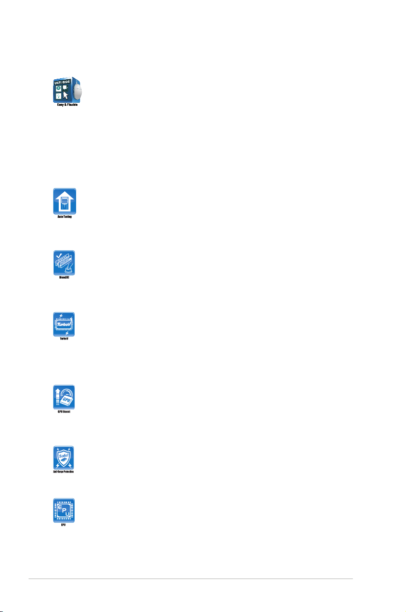
Auto Tuning
Auto Tuning is an intelligent tool that automates overclocking to achieve
a total system level up. This tool also provides stability testing. Even O.C.
beginners can achieve extreme yet stable overclocking results with Auto
Tuning!
MemOK!
MemOK! quickly ensures memory boot compatibility. This remarkable
memory rescue tool requires a mere push of the button to patch memory
issues. MemOK! determines failsafe settings and dramatically improves
your system boot success. Get your system up and running in no time.
ASUS TurboV
Feel the adrenaline rush of real-time OC-now a reality with the ASUS
TurboV. This easy OC tool allows you to overclock without exiting or
rebooting the OS; and its user-friendly interface makes overclock with just
a few clicks away. Moreover, the ASUS OC proles in TurboV provides
the best O.C. settings in different scenarios.
GPU Boost
GPU Boost overclocks the integrated GPU in real time for the best
graphics performance. User-friendly UI facilitates exible frequency and
voltage adjustments. Its ability to deliver multiple overclocking proles
also provides rapid and stable system-level upgrades.
ASUS Anti-Surge Protection
This special design prevents expensive devices and the motherboard
from damage caused by power surges from switching power supply
(PSU).
ASUS EPU
ASUS EPU is a unique power saving technology that detects the current
system loadings and adjusts the power consumption in real time.
1-4 Chapter 1: Product introduction
Fan Xpert
ASUS Fan Xpert intelligently allows you to adjust the CPU and chassis
fan speeds according to different ambient temperatures caused by
different climate conditions in different geographic regions and your PC’s
loading. The built-in variety of useful proles offer exible controls of fan
speed to achieve a quiet and cool environment.
Fanless Design: stylish heatpipe solution
The stylish heatpipe features a 0-dB thermal solution that offers users
a noiseless PC environment. Not only the beautiful shape upgrades the
visual enjoyment for motherboard users, but also the heatsink design
lowers the temperature of the chipset and power phase area through
high efcient heat-exchange. Combined with usability and aesthetics,
the ASUS stylish heatpipe will give users an extremely silent and cooling
experience with the elegant appearance!
AI Suite II
With its user-friendly interface, ASUS AI Suite II consolidates ASUS
features into one simple to use software package. It allows you you to
supervise overclocking, energy management, fan speed control, voltage
and sensor readings. All in one software offers diverse and ease to use
functions, with no need to switch back and forth between different utilities.
Ai Charger+
ASUS Ai Charger+, the latest Ai Charger* version, brings you to a new
level of USB3.0 fast charging experience. With its easy and user-friendly
interface, you can not only easily charge iPod, iPhone and iPad, but also
BC 1.1** standard mobile devices three times*** as fast as before.
* Ai Charger is ASUS unique fast-charging software which supports iPod, iPhone and
iPad.
** Check your USB mobile device manufacturer if it fully supports the BC 1.1 function.
*** The actual charging speed may vary with your USB device’s conditions.
ASUS MyLogo2™
This feature allows you to convert your favorite photo into a 256-color
boot logo for a more colorful and vivid image on your screen.
ASUS CrashFree BIOS 3
ASUS CrashFree BIOS 3 is an auto-recovery tool that allows you to
restore a corrupted BIOS le using the bundled support DVD or USB
ash disk that contains the latest BIOS le.
ASUS EZ Flash 2
ASUS EZ Flash 2 is a utility that allows you to update the BIOS without
using an OS-based utility.
ASUS P8Z68-V LX 1-5

C.P.R. (CPU Parameter Recall)
The BIOS C.P.R. feature automatically restores the CPU default settings
when the system hangs due to overclocking failure. C.P.R. eliminates the
need to open the system chassis and clear the RTC data. Simply shut
down and reboot the system, and the BIOS automatically restores the
CPU parameters to their default settings.
ErP ready
The motherboard is European Union´s Energy-related Products (ErP)
ready, and ErP requires products to meet certain energy efciency
requirements in regards to energy consumptions. This is in line with
ASUS vision of creating environment-friendly and energy-efcient
products through product design and innovation to reduce carbon
footprint of the product and thus mitigate environmental impacts.
1.3.3 Intel® Smart Response Technology & LucidLogix® VirtuTM
Solution
Intel® Smart Response Technology
Intel® Smart Response Technology boosts overall system performance. It uses an installed
fast SSD (min 18.6GB available) as a cache for frequently accessed operations, speeding up
hard drive/ main memory interaction. Key benets are expedited hard drive speeds, reduced
load and wait times, and maximized storage utilization. Power consumption also goes down
by reducing unnecessary hard drive spin.
• Intel® Smart Response Technology supports Windows® 7/ Vista operating systems.
• Intel® Smart Response Technology is supported by 2nd generation Intel® Core™
processor family.
• Operating systems must be installed on the HDD to launch Intel® Smart Response
Technology. The capacity of the SSD is reserved for caching function.
• Before applying Intel® Smart Response Technology, set the SATA Mode BIOS item to
[RAID mode] in BIOS setup. Refer to SATA Conguration in Chapter 2 for details.
To install Intel® Smart Response Technology:
1. Place the support DVD to the optical drive. The Drivers installation tab appears if your
computer has enabled the Autorun feature.
2. Click the Drivers tab, then click Intel® Rapid Storage Technology Driver software.
3. Follow the onscreen instructions to complete installation.
To use Intel® Smart Response Technology:
1-6 Chapter 1: Product introduction
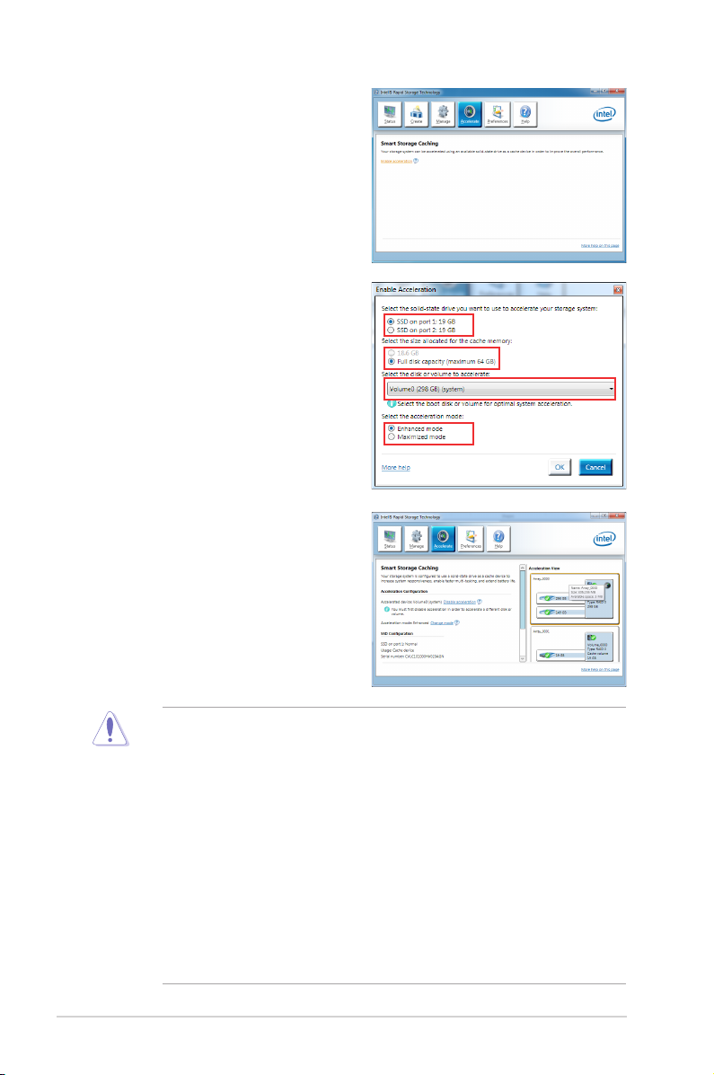
1. Click Accelerate to launch Smart
Response Technology settings.
2. a. Select the SSD you want to use to
accelerate your storage system.
b. Select the size allocated for SSD
caching.
c. Select which HDD for caching.
d. Enhanced mode:WRITE THROUGH,
write to SSD and HDD at the same
time.
Maximized mode:WRITE BACK,
write to SSD and write back to HDD in
a later time.
3. Select Disable Acceleration to disable
this function and select Change Mode to
switch acceleration mode to Enhanced/
Maximus.
• Only Intel® internal SATA ports (gray and blue) support Intel® Smart Response
Technology.
• You need at least one SSD (>18.6GB) and one HDD as a set to enable Intel
Response Technology. A single SSD can only be assigned to one HDD for caching.
• The maximum caching size on the SSD is 64GB. If the SSD exceeds 64GB, storage
capacity left out of caching can still be identied by the system for normal storage.
• Be sure to disable the acceleration function of Intel® Smart Response Technology under
OS when applying the actions below:
– Removing or replacing the SSD
– Updating IRST 10.5 driver
– Updating BIOS
• If you want to restore the OS, go to BIOS Option ROM utility and select Acceleration
Options to disable Intel® Smart Response Technology.
• The performance of Intel® Smart Response Technology varies by SSD.
ASUS P8Z68-V LX 1-7
®
Smart
LucidLogix® Virtu™ solution
LucidLogix® Virtu™ is a new generation GPU virtualization software that blurs the line
between embedded graphics and discrete GPU for increased graphics performance. Its GPU
virtualization dynamically assigns tasks to the best available graphics resources based on
power, performance and system load. It allows users to fully utilize the unique capabilities
of advanced Sandy Bridge multimedia features alongside the high end 3D rendering
performance provided by installed graphics cards. For users with diverse needs, LucidLogix®
Virtu™ GPU virtualization provides great exibility and efciency.
• LucidLogix® Virtu™ supports Windows® 7 operating systems.
• Intel® Quick Sync Video feature is supported by Intel® Core™ processor family.
• Supports NVIDIA® GF4xx/ 5xx series & AMD® HD5xxx/ 6xxx series graphic cards.
Hardware installation
To install LucidLogix® Virtu™:
1. Place the support DVD to the optical drive. The Drivers installation tab appears if your
computer has enabled the Autorun feature.
2. Click the Drivers tab, then click LucidLogix® Virtu™ software.
3. Follow the onscreen instructions to complete installation.
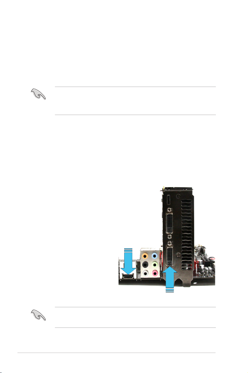
i-Mode
To use LucidLogix® Virtu™ solution in i-Mode,
display must be always connected to Sandy
Bridge motherboard video output.
d-Mode (recommended mode)
To use LucidLogix® Virtu™ solution in
d-Mode, display must be connected to the
discrete GPU installed in the system
Both i-Mode and d-Mode enjoy the performance of Intel® Sandy Bridge built-in
media features and discrete card. d-Mode is recommended for enhanced 3D gamingd-Mode is recommended for enhanced 3D gamingis recommended for enhanced 3D gaming
performance.
1-8 Chapter 1: Product introduction
i-Mode (output from
the Sandy Bridge
GPU)
d-Mode (output from the discrete GPU)

1.4 Before you proceed
Take note of the following precautions before you install motherboard components or change
any motherboard settings.
• Unplug the power cord from the wall socket before touching any component.
• Before handling components, use a grounded wrist strap or touch a safely grounded
object or a metal object, such as the power supply case, to avoid damaging them due to
static electricity.
• Hold components by the edges to avoid touching the ICs on them.
• Whenever you uninstall any component, place it on a grounded antistatic pad or in the
bag that came with the component.
• Before you install or remove any component, ensure that the ATX power supply is
switched off or the power cord is detached from the power supply. Failure to do so may
cause severe damage to the motherboard, peripherals, or components.
ASUS P8Z68-V LX 1-9
1.5 Motherboard overview
Before you install the motherboard, study the conguration of your chassis to ensure that the
motherboard ts into it.
Ensure that you unplug the power cord before installing or removing the motherboard.
Failure to do so can cause you physical injury and damage motherboard components.
1.5.1 Placement direction
When installing the motherboard, ensure that you place it into the chassis in the correct
orientation. The edge with external ports goes to the rear part of the chassis as indicated in
the image below.
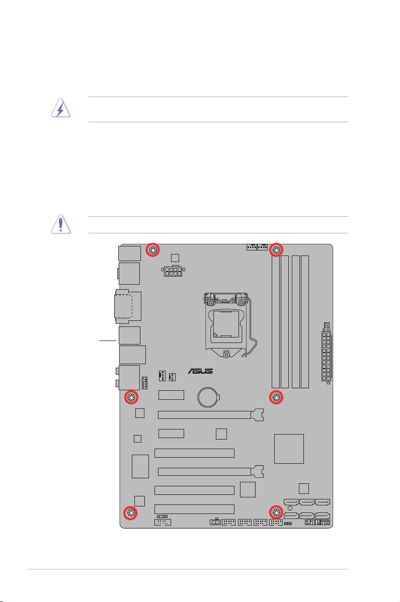
1.5.2 Screw holes
Place six screws into the holes indicated by circles to secure the motherboard to the chassis.
Do not overtighten the screws! Doing so can damage the motherboard.
Place this side
towards the rear
of the chassis
1-10 Chapter 1: Product introduction
P8Z68-V LX
PCIEX16_1
PCIEX16_2
PCIEX1_2
PCIEX1_1
PCI1
PCI2
PCI3
USB56USB78USB910USB1112
PANEL
SPDIF_OUT
AAFP
CPU_FAN
CHA_FAN2
CHA_FAN1
PWR_FAN
Lithium Cell
CMOS Power
Super
I/O
ALC
887
EPU
RTL
8111E
TPU
COM1
64Mb
BIOS
SB_PWR
CLRTC
22.9cm(9.0in)
30.5cm(12.0in)
Intel
®
Z68
DDR3 DIMM_A1 (64bit, 240-pin module)
DDR3 DIMM_A2 (64bit, 240-pin module)
DDR3 DIMM_B1 (64bit, 240-pin module)
DDR3 DIMM_B2 (64bit, 240-pin module)
USB3_12
ASM
1083
ASM
1042
SATA3G_2 SATA3G_3 SATA3G_4
SATA3G_1
SATA6G_2 SATA6G_1
MemOK!
DRAM_LED
TPU
ELED730
EATXPWR
EATX12V
LGA1155
AUDIO
KB_USB34
LAN1_USB12
SPDIF_O2
HDMI
DVI_VGA
1 2 423
1
5
6
8
7
1517 1314 12 11 10
16
9
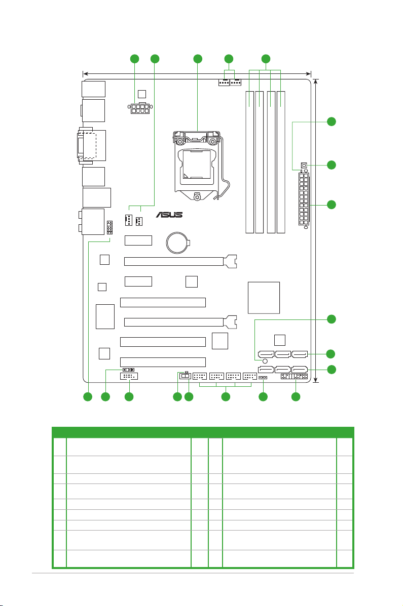
1.5.3 Motherboard layout
1.5.4 Layout contents
Connectors/Jumpers/Slots/LED Page Connectors/Jumpers/Slots/LED Page
ATX power connectors
1.
(24-pin EATXPWR, 8-pin EATX12V)
CPU, Chassis and power fan connectors (4-pin
2.
CPU_FAN, 4-pin CHA_FAN1/2, 3-pin PWR_FAN)
3. Intel® CPU socket 1-12 12 USB connectors (10-1 pin USB5~12) 1-32
4. DDR3 DIMM sockets 1-17
5. DRAM LED 1-37 14 TPU LED (ELED 730) 1-37
6. MemOK! switch 1-35 15. Serial port connectors (10-1 pin COM1) 1-29
7. Onboard LED (SB_PWR) 1-36 16. Digital audio connector (4-1 pin SPDIF_OUT) 1-30
Intel® Z68 Serial ATA 3.0 Gb/s connectors
8.
(7-pin SATA3G_1–4 [blue])
ASUS P8Z68-V LX 1-11
In te l® Z68 Se ri al ATA 6. 0 Gb/ s con ne ct ors
9.
(7-pin SATA6G_1/2 [gray])
1-33 10 System panel connector (20-8 pin PANEL) 1-34
1-32 11. Clear RTC RAM (3-pin CLRTC) 1-26
.
TPU switch 1-36
13.
1-30 17. Front panel audio connector (10-1 pin AAFP) 1-29
1-31

1.6 Central Processing Unit (CPU)
P8Z68-V LX
P8Z68-V LX CPU socket LGA1155
The motherboard comes with a surface mount LGA1155 socket designed for the Intel® 2nd
Generation Core™ i7 / Core™ i5 / Core™ i3 processors.
Unplug all power cables before installing the CPU.
• Upon purchase of the motherboard, ensure that the PnP cap is on the socket and the
socket contacts are not bent. Contact your retailer immediately if the PnP cap is missing,
or if you see any damage to the PnP cap/socket contacts/motherboard components.
ASUS will shoulder the cost of repair only if the damage is shipment/transit-related.
• Keep the cap after installing the motherboard. ASUS will process Return Merchandise
Authorization (RMA) requests only if the motherboard comes with the cap on the
LGA1155 socket.
• The product warranty does not cover damage to the socket contacts resulting from
incorrect CPU installation/removal, or misplacement/loss/incorrect removal of the PnP
cap.
1.6.1 Installing the CPU
To install a CPU:
1. Locate the CPU socket on the motherboard.
2. Press the load lever with your thumb (A),
Load lever
and then move it to the right (B) until it is
released from the retention tab.
To prevent damage to the socket pins,
do not remove the PnP cap unless
you are installing a CPU.
Retention tab
1-12 Chapter 1: Product introduction
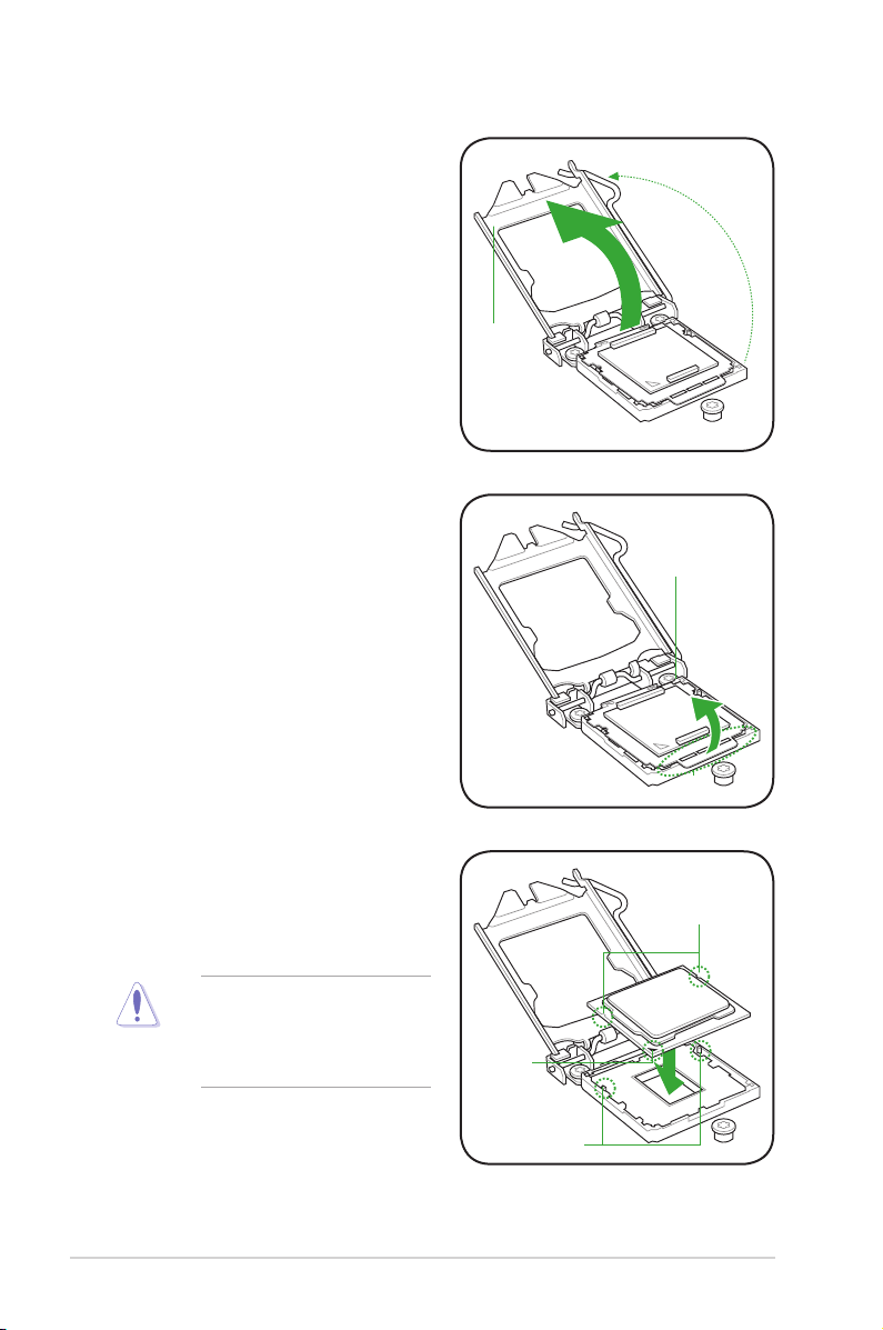
3. Lift the load lever in the direction of the
arrow until the load plate is completely
lifted.
4. Remove the PnP cap from the CPU
socket by lifting the tab only.
Load plate
PnP cap
5. Position the CPU over the socket,
ensuring that the gold triangle is on the
bottom-left corner of the socket, and
then t the socket alignment keys into
CPU notches
the CPU notches.
The CPU ts in only one correct
orientation. DO NOT force the CPU
into the socket to prevent bending
the connectors on the socket and
damaging the CPU!
ASUS P8Z68-V LX 1-13
Gold
triangle
mark
Alignment keys
Loading…
Найди любой мануал:
Например: Sony VGN-FW460J/T
Вы можете бесплатно скачать Руководство по эксплуатации для ASUS P8Z68V_LX.
Также вы сможете прочесть онлайн этот документ без скачивания.
Скачать Руководство по эксплуатации для ASUS P8Z68V_LX
Тип файла
PDF
Размер
5.82 Mb
Кол-во страниц
82
Просмотров
2895
Читать онлайн Руководство по эксплуатации для ASUS P8Z68V_LX (Страница 1)

Другие Материнские платы ASUS P8Z68V_LX
Топ ASUS Материнские платы
Ранее вы смотрели
Эта страница полезна для вас? Поделитесь ссылкой:
- Инструкции и руководства
- Бренды
- ASUS
- p8z68-v lx
- Справочник Пользователя
Оглавление
- Вступление
- Упаковка и комплектация
- Дизайн и особенности платы
- Система охлаждения
- Система питания
- Технические характеристики
- Возможности BIOS Setup
- Тестовый стенд
- Проверка разгона
- Установка напряжений
- Разгон по BCLK
- Разгон оперативной памяти
- Разгон процессора
- Фирменное ПО
- Встроенный звук
- Тестирование производительности
- Методика тестирования
- Результаты тестов
- Заключение
Вступление
Лаборатория Overclockers.ru продолжает знакомить своих читателей с материнскими платами нижнего ценового диапазона, основанными на наборе логики Intel Z68 Express. Ранее были протестированы ASRock Z68 Pro3 Gen3 и Gigabyte GA-Z68AP-D3, в продолжение темы будет рассмотрена ASUS P8Z68-V LX — прямой ценовой конкурент для вышеупомянутых плат.
Начнем обзор, как обычно, с упаковки и комплекта поставки.
Упаковка и комплектация

Оформление коробки не отличается оригинальностью: сама основа раскрашена в темные тона, выделяются лишь крупные буквы названия модели, да логотипы поддерживаемых технологий. Сильного внимания такая упаковка не привлекает, зато информативна.

С обратной стороны можно обнаружить фотографию продукта и перечисление его основных характеристик, что позволяет в какой-то степени избежать покупки «кота в мешке». Присутствует и порция неизбежной рекламы в виде описания работы части технологий.
При открытии коробки взгляду предстает непосредственно материнская плата, упакованная в антистатический пакет:

Зафиксирована она плотно, проблем с транспортировкой быть не должно. Комплект поставки частично расположен на дне коробки, а частично (шлейфы SATA) – внутри картонного фиксатора над платой.
В список аксессуаров входит:

- Заглушка на заднюю панель;
- Два кабеля SATA;
- Руководство пользователя;
- Краткая инструкция по установке;
- Диск с программным обеспечением.
Комплект поставки предельно урезан, ожидать чего-либо другого для бюджетного варианта было бы глупо. К положительным моментам не отнесешь ни наличие всего двух шлейфов SATA, ни отсутствие в комплекте поставки переходника Q-Connector.
Дизайн и особенности платы
Размеры ASUS P8Z68-V LX – 305×229 мм, что уже полноразмерных материнских плат форм-фактора ATX (305х244 мм), однако она все же шире, чем протестированные ранее Gigabyte GA-Z68AP-D3 (305×215 мм) и ASRock Z68 Pro3 Gen3 (305×191 мм).

Конечно, присутствуют нераспаянные элементы, что свойственно моделям данного ценового диапазона, но все же «пустой» материнская плата не выглядит. В то же время, бросается в глаза бюджетность продукта – особенно это заметно по преобразователю питания процессора и отсутствию радиаторов на транзисторах. Что ж, еще предстоит узнать, как такое решение проявит себя при разгоне.
Обратная сторона:

Каких-либо элементов с обратной стороны нет. Можно разве что обратить внимание на винтовое крепление радиатора системы охлаждения чипсета и на производителя процессорного разъема — Foxconn.
Расположение элементов:

Под DDR3 память распаяно четыре слота, которые оборудованы защелками с обеих сторон:

Поскольку графический PCI-E X16 расположен на высоте второго разъема расширения (верхним/первым является PCI-E X1), то установленная в систему видеокарта не перекроет доступ к слотам оперативной памяти.
Производителем заявлены режимы работы DDR3 1066 / 1333 / 1600 / 1866 (разгон) / 2133 (разгон) / 2200 (разгон). При открытии руководства пользователя можно увидеть надпись «Due CPU behavior, DDR3 2200/2000/1800 MHz memory module will run at DDR3 2133/1866/1600 MHz frequency as default.», отсюда следует, что память DDR3-2200 будет работать на частоте 2133 МГц. Получается, что поддержка DDR3-2200 заявлена чисто номинально, для красивой надписи, и с тем же успехом можно было вывести в спецификацию режим DDR3-[вставить любое число]. Максимальный заявленный объем памяти в 32 Гбайта говорит о поддержке платой модулей памяти объемом 8 Гбайт.
Для активации режима Dual Channel необходимо устанавливать модули памяти в разъемы одинакового цвета, то есть через один. Для оптимальной совместимости в случае использования двух модулей памяти производителем рекомендуется устанавливать их в голубые слоты (DDR3_A2 и DDR3_B2). Допускается работа Dual Channel при использовании всех четырех планок памяти.
Рядом со слотами оперативной памяти можно обнаружить светодиод «DRAM LED», а также кнопку MemOK!:

Диод загорается в процессе инициализации памяти, после чего потухает. Если светит постоянно, а система не стартует – то следует зажать кнопку. В таком случае для оперативной памяти будут загружены максимально расслабленные настройки таймингов с целью обеспечения наибольшей совместимости.
Роль набора системной логики отведена одной микросхеме – Intel Z68 Express:

Все материнские платы на Z68 были выпущены уже после исправления ошибки с портами SATA2, и все они относятся к ревизии B3.
Telegram-канал @overclockers_news — теперь в новом формате. Подписывайся, чтобы быть в курсе всех новостей!
Telegram-канал @overclockers_news — обновлённый формат нашего канала. Подписывайся, чтобы быть в курсе всех новостей!

By registering your device, you can easily manage your product warranty, get technical support and keep track of your repair status.
Register Product
Manual
Version F6771
4.46 MB
2011/12/01
P8Z68-V LX user’s manual(French)
Version U6771
1015.08 KB
2011/08/03
P8Z68-V LX European Quick Start Guide for Multiple Languages
Version E6771
5.44 MB
2011/08/03
P8Z68-V LX User’s Manual (English)
Version A6771
1.51 MB
2011/08/03
P8Z68-V LX Asian Quick Start Guide for Multiple Languages
Version T6771
4.23 MB
2011/07/26
P8Z68-V LX User’s Manual (Traditional Chinese)
Version C6771
4.4 MB
2011/07/26
P8Z68-V LX User’s Manual (Simplified Chinese)