
Declaration of Conformity with regard to the R&TTE Directive 1999/5/EC
Manufacturer:
Pioneer Corporation
4-1, Meguro 1-chome, Meguro-ku
Tokyo 153-8654, Japan
EU Representative’s:
Pioneer Europe NV
Haven 1087, Keetberglaan 1,
9120 Melsele, Belgium
http://www.pioneer.eu
English:
Hereby, Pioneer, declares that this DEH-600BT is in
compliance with the essential requirements and other
relevant provisions of Directive 1999/5/EC.
Suomi:
Pioneer vakuuttaa täten että DEH-600BT tyyppinen
laite on direktiivin 1999/5/EY oleellisten vaatimusten ja
sitä koskevien direktiivin muiden ehtojen mukainen.
Nederlands:
Hierbij verklaart Pioneer dat het toestel DEH-600BT
in overeenstemming is met de essentiële eisen en de
andere relevante bepalingen van richtlijn 1999/5/EG
Français:
Par la présente Pioneer déclare que l’appareil DEH-
600BT est conforme aux exigences essentielles et aux
autres dispositions pertinentes de la directive 1999/5/
CE
Svenska:
Härmed intygar Pioneer att denna DEH-600BT står I
överensstämmelse med de väsentliga egenskapskrav
och övriga relevanta bestämmelser som framgår av
direktiv 1999/5/EG.
Dansk:
Undertegnede Pioneer erklærer herved, at følgende
udstyr DEH-600BT overholder de væsentlige krav og
øvrige relevante krav i direktiv 1999/5/EF
Deutsch:
Hiermit erklärt Pioneer, dass sich dieses DEH-600BT
in Übereinstimmung mit den grundlegenden Anforde-
rungen und den anderen relevanten Vorschriften der
Richtlinie 1999/5/EG befi ndet». (BMWi)
Ελληνικά:
ΜΕ ΤΗΝ ΠΑΡΟΥΣΑ Pioneer ΔΗΛΩΝΕΙ ΟΤΙ DEH-
600BT ΣΥΜΜΟΡΦΩΝΕΤΑΙ ΠΡΟΣ ΤΙΣ ΟΥΣΙΩΔΕΙΣ
ΑΠΑΙΤΗΣΕΙΣ ΚΑΙ ΤΙΣ ΛΟΙΠΕΣ ΣΧΕΤΙΚΕΣ ΔΙΑΤΑΞΕΙΣ
ΤΗΣ ΟΔΗΓΙΑΣ 1999/5/ΕΚ
Italiano:
Con la presente Pioneer dichiara che questo DEH-
600BT è conforme ai requisiti essenziali ed alle altre
disposizioni pertinenti stabilite dalla direttiva 1999/5/
CE.
Español:
Por medio de la presente Pioneer declara que el DEH-
600BT cumple con los requisitos esenciales y cuales-
quiera otras disposiciones aplicables o exigibles de la
Directiva 1999/5/CE
Português:
Pioneer declara que este DEH-600BT está conforme
com os requisitos essenciais e outras disposições da
Directiva 1999/5/CE.
Čeština:
Pioneer tímto prohlašuje, že tento DEH-600BT je ve
shodě se základními požadavky a dalšími příslušnými
ustanoveními směrnice 1999/5/ES
Eesti:
Käesolevaga kinnitab Pioneer seadme DEH-600BT
vastavust direktiivi 1999/5/EÜ põhinõuetele ja
nimetatud direktiivist tulenevatele teistele asjakohastele
sätetele.
Magyar:
Alulírott, Pioneer nyilatkozom, hogy a DEH-600BT
megfelel a vonatkozó alapvetõ követelményeknek és
az 1999/5/EC irányelv egyéb elõírásainak.
Latviešu valoda:
Ar šo Pioneer deklarē, ka DEH-600BT atbilst Direktīvas
1999/5/EK būtiskajām prasībām un citiem ar to
saistītajiem noteikumiem.
Lietuvių kalba:
Šiuo Pioneer deklaruoja, kad šis DEH-600BT atitinka
esminius reikalavimus ir kitas 1999/5/EB Direktyvos
nuostatas.
Malti:
Hawnhekk, Pioneer jiddikjara li dan DEH-600BT
jikkonforma mal-ħtiġijiet essenzjali u ma provvedimenti
oħrajn relevanti li hemm fi d-Dirrettiva 1999/5/EC
Slovenčina:
Pioneer týmto vyhlasuje, že DEH-600BT spĺňa základ-
né požiadavky a všetky príslušné ustanovenia Smerni-
ce 1999/5/ES.
Slovenščina:
Pioneer izjavlja, da je ta DEH-600BT v skladu z
bistvenimi zahtevami in ostalimi relevantnimi določili
direktive 1999/5/ES.
Română:
Prin prezenta, Pioneer declara ca acest DEH-600BT
este in conformitate cu cerintele esentiale si alte
prevederi ale Directivei 1999/5/EU.
български:
С настоящето, Pioneer декларира, че този DEH-
600BT отговаря на основните изисквания и други
съответни постановления на Директива 1999/5/EC.
Polski:
Niniejszym Pioneer oświadcza, że DEH-600BT jest
zgodny z zasadniczymi wymogami oraz pozostałymi
stosownymi postanowieniami Dyrektywy 1999/5/EC
Norsk:
Pioneer erklærer herved at utstyret DEH-600BT er i
samsvar med de grunnleggende krav og øvrige rele-
vante krav i direktiv 1999/5/EF.
Íslenska:
Hér með lýsir Pioneer yfi r því að DEH-600BT er í
samræmi við grunnkröfur og aðrar kröfur, sem gerðar
eru í tilskipun 1999/5/EC
Ru
2
Если вы желаете утилизировать данное
изделие, не выбрасывайте его вместе с
обычным бытовым мусором. Существует
отдельная система сбора использованных
электронных изделий в соответствии с за-
конодательством, которая предполагает со-
ответствующее обращение, возврат и
переработку.
Частные лица в странах Евросоюза, Швей-
царии и Норвегии могут бесплатно возвра-
щать использованные электронные
изделия в специализированные пункты
приема или в магазин (при покупке анало-
гичного нового устройства).
Если Ваша страна не указана в приведен-
ном выше перечне, обращайтесь в органы
местного управления за инструкциями по
правильной утилизации продукта.
Тем самым Вы обеспечите утилизацию
Вашего изделия с соблюдением обязатель-
ных процедур по обработке, утилизации и
вторичной переработке и, таким образом,
предотвратите потенциальное негативное
воздействие на окружающую среду и здо-
ровье людей.
Сведения об этом устройстве
Частоты тюнера в этом устройстве рас-
пределены для использования в Западной
Европе, Азии, на Ближнем Востоке, в
Африке и Океании. При использовании в
других регионах качество приема может
быть плохим. Функция RDS (радиове-
щательная система передачи информа-
ции) доступна только в регионах, в которых
имеются FM-станции, передающие сигна-
лы RDS.
ВНИМАНИЕ
! Не допускайте попадания жидкости на
данное устройство. Это может повлечь по-
ражение электрическим током. Кроме того,
попадание жидкости в устройство может
стать причиной его выхода из строя,
перегрева и появления дыма.
! “ЛАЗЕРНЫЙ ПРОДУКТ КЛАССА 1”
Это изделие оснащено лазерным диодом
класса выше 1. В целях обеспечения пол-
ной безопасности не снимайте какие-либо
крышки и не пытайтесь проникнуть внутрь
изделия. Ремонт должен выполняться ква-
лифицированным специалистом.
! Pioneer CarStereo-Pass предназначен для
использования только в Германии.
! Держите это руководство под рукой в
качестве справочника по правилам эк-
сплуатации и мерам предосторожности.
! Всегда сохраняйте уровень громкости до-
статочно низким, чтобы Вы могли слышать
звуки снаружи машины.
! Оберегайте это устройство от воздействия
влажности.
! При отключении или разряде батареи пам-
ять предварительных настроек будет
стерта и потребуется ее повторное про-
граммирование.
О формате WMA
Логотип Windows Media™, напечатанный
на коробке, указывает на возможность вос-
произведения данных в формате WMA.
Windows Media
и логотип Windows являют-
ся товарными знаками или зарегистриро-
ванными товарными знаками Microsoft
Corporation
в Соединенных Штатах и/или
других странах.
Перед началом эксплуатации
Ru
6
Раздел
01
Условия эксплуатации 7, Посетите наш сайт, В случае возникновения неполадок
Перезагрузка микропроцессора, Перед началом эксплуатации Чат поддержки
- Изображение
- Текст
! Это устройство может неверно вос-
производить некоторые файлы форма-
та WMA в зависимости от приложений,
использованных для их записи.
О формате MP3
Поставка этого изделия дает право только
на его частное и некоммерческое исполь-
зование и не предоставляет лицензии и не
подразумевает право использования этого
изделия в любых коммерческих (т.е. прино-
сящих прибыль) прямых трансляциях
(
телевизионных, спутниковых, кабельных
и/или любых других), вещании/потоковой
передаче через Интернет, локальных сетях
и/или других сетях или в других электрон-
ных системах распространения, таких как
системы платного аудио и аудио по запро-
су. Для такого использования необходима
специальная лицензия. Для получения до-
полнительной информации посетите
http://www.mp3licensing.com.
О технологии Bluetooth
Bluetooth-
это технология, позволяющая ус-
танавливать радиосоединение на неболь-
ших расстояниях; она разработана в
качестве альтернативы кабельному по-
дключению мобильных телефонов, КПК и
других устройств. Bluetooth позволяет
передавать речь и данные со скоростьюдо
1
Мбит/с в диапазоне частот 2,4 ГГц. Разра-
ботка технологии Bluetooth была начата в
1998
году группой заинтересованных ком-
паний (SIG), куда вошли Ericsson Inc., Intel
Corp., Nokia Corp., Toshiba
и IBM; в на-
стоящее время работы в этой сфере ведут
почти 2 000 компаний по всему миру.
! Товарный знак Bluetooth (слово и лого-
тип) принадлежит компании Bluetooth
SIG, Inc.;
использование корпорацией
Pioneer
этих товарных знаков раз-
решено соответствующей лицензией.
Прочие товарные знаки и торговые
марки принадлежат соответствующим
владельцам.
Условия эксплуатации
Это устройство должно эксплуатироваться
в указанном ниже диапазоне температур.
Диапазон рабочих температур: от -10 °C до
+60 °C (
от 14 °F до 140 °F)
Температура при выполнении теста
EN300328 ETC: -20 °C
и +55 °C (-4 °F и 131
°F)
Посетите наш сайт
Посетите наш сайт:
http://www.pioneer-rus.ru
! Зарегистрируйте приобретенное
изделие. Мы сохраним сведения о
Вашей покупке, что поможет Вам ссы-
латься на эту информациюв случае
страхового требования по причине
потери или кражи.
! Самуюсвежуюинформациюо Pioneer
Corporation
можно получить на нашем
веб-сайте.
В случае возникновения
неполадок
При неполадках в работе этого изделия
свяжитесь с торговым представителем
компании-производителя или с ближайшим
сервисным пунктом Pioneer.
Перезагрузка
микропроцессора
Микропроцессор следует перезагружать в
следующих случаях:
Перед началом эксплуатации
Ru
7
Раздел
01
Перед
началом
эксплуатации
Защита вашего устройства от кражи 8, Снятие передней панели 8, Установка передней панели 8
Защита вашего устройства от кражи, Перед началом эксплуатации, Снятие передней панели, Установка передней панели Чат поддержки
- Изображение
- Текст
! Перед первым использованием этого
устройства после установки
! Если устройство работает неправильно
! Если на дисплее появляются странные
или неверные сообщения
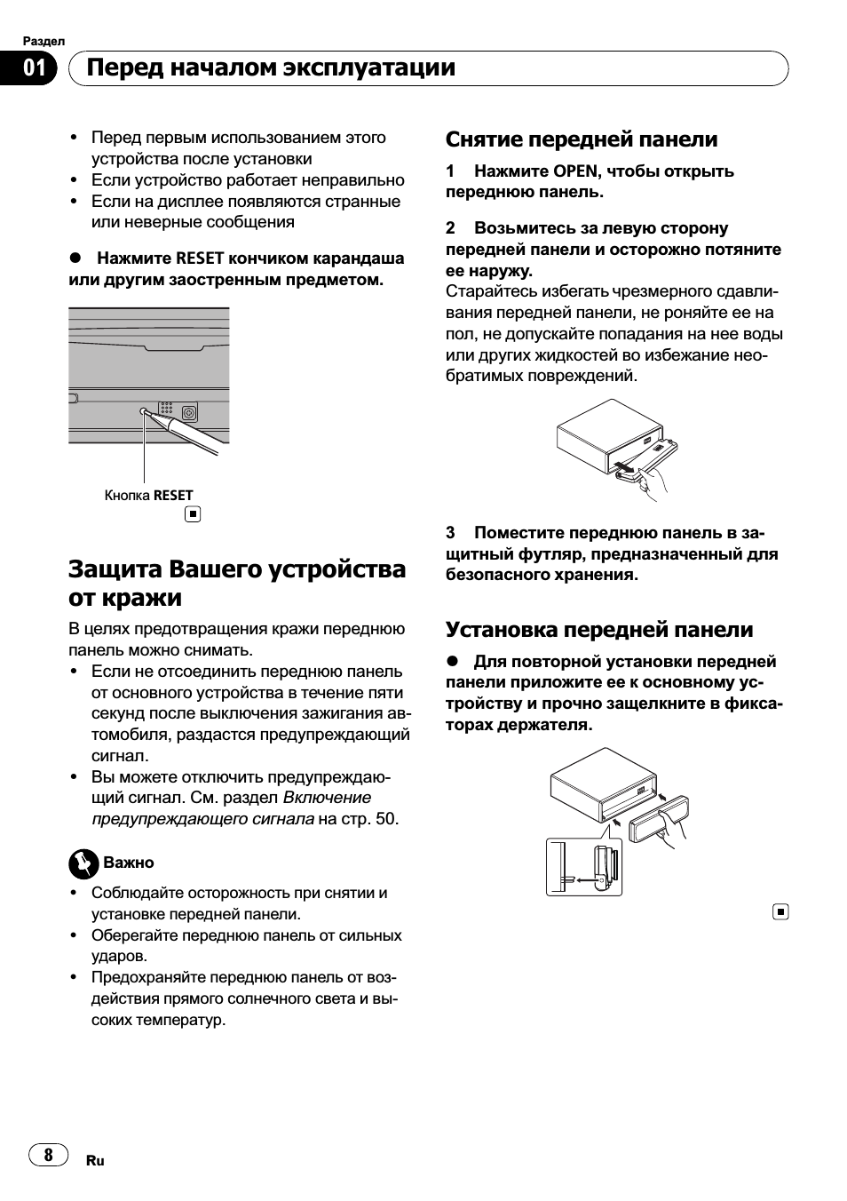
% Нажмите RESET кончиком карандаша
или другим заостренным предметом.
Кнопка RESET
Защита Вашего устройства
от кражи
В целях предотвращения кражи переднюю
панель можно снимать.
! Если не отсоединить переднюю панель
от основного устройства в течение пяти
секунд после выключения зажигания ав-
томобиля, раздастся предупреждающий
сигнал.
! Вы можете отключить предупреждаю-
щий сигнал. См. раздел
Включение
предупреждающего сигнала на стр. 50.
Важно
! Соблюдайте осторожность при снятии и
установке передней панели.
! Оберегайте переднюю панель от сильных
ударов.
! Предохраняйте переднюю панель от воз-
действия прямого солнечного света и вы-
соких температур.
Снятие передней панели
1 Нажмите OPEN, чтобы открыть
переднюю панель.
2 Возьмитесь за левую сторону
передней панели и осторожно потяните
ее наружу.
Старайтесь избегать чрезмерного сдавли-
вания передней панели, не роняйте ее на
пол, не допускайте попадания на нее воды
или других жидкостей во избежание нео-
братимых повреждений.
3 Поместите переднюю панель в за-
щитный футляр, предназначенный для
безопасного хранения.
Установка передней панели
% Для повторной установки передней
панели приложите ее к основному ус-
тройству и прочно защелкните в фикса-
торах держателя.
Перед началом эксплуатации
Ru
8
Раздел
01
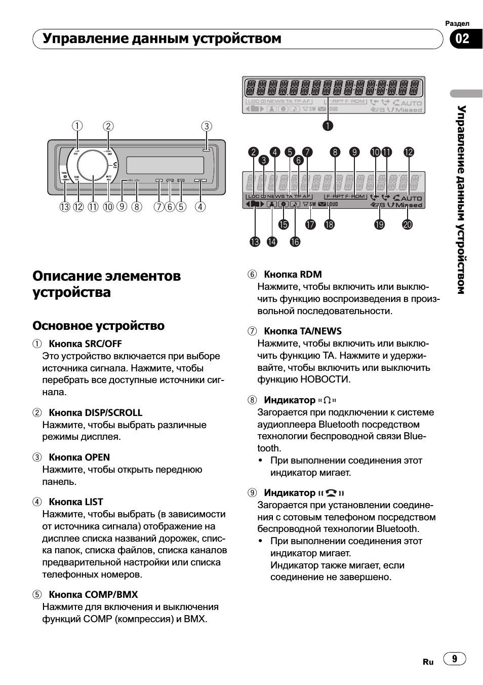
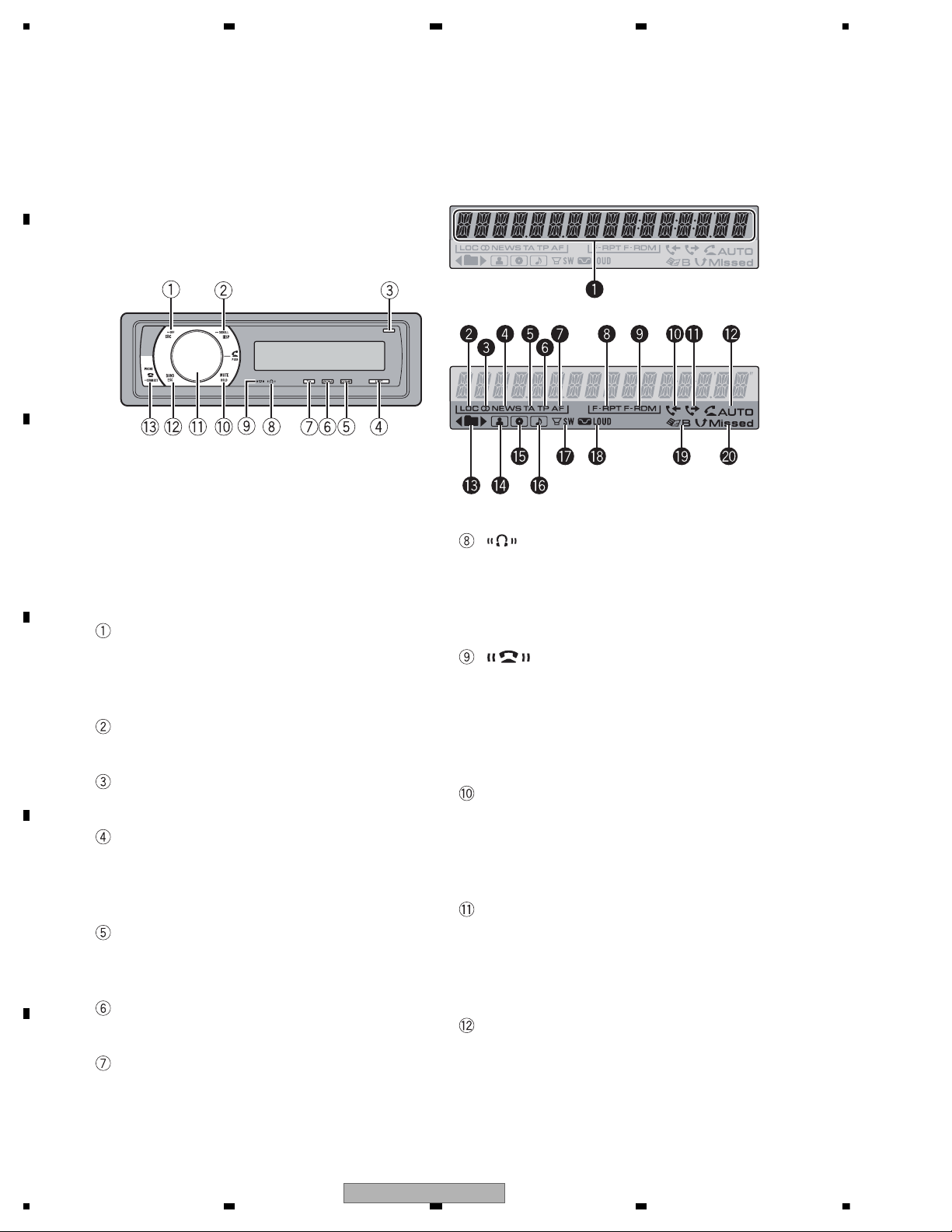
Описание элементов
устройства
Основное устройство
1 Кнопка SRC/OFF
Это устройство включается при выборе
источника сигнала. Нажмите, чтобы
перебрать все доступные источники сиг-
нала.
2 Кнопка DISP/SCROLL
Нажмите, чтобы выбрать различные
режимы дисплея.
3 Кнопка OPEN
Нажмите, чтобы открыть переднюю
панель.
4 Кнопка LIST
Нажмите, чтобы выбрать (в зависимости
от источника сигнала) отображение на
дисплее списка названий дорожек, спис-
ка папок, списка файлов, списка каналов
предварительной настройки или списка
телефонных номеров.
5 Кнопка COMP/BMX
Нажмите для включения и выключения
функций COMP (компрессия) и BMX.
6 Кнопка RDM
Нажмите, чтобы включить или выклю-
чить функциювоспроизведения в произ-
вольной последовательности.
7 Кнопка TA/NEWS
Нажмите, чтобы включить или выклю-
чить функцию TA. Нажмите и удержи-
вайте, чтобы включить или выключить
функциюНОВОСТИ.
8 Индикатор
Загорается при подключении к системе
аудиоплеера Bluetooth посредством
технологии беспроводной связи Blue-
tooth.
! При выполнении соединения этот
индикатор мигает.
9 Индикатор
Загорается при установлении соедине-
ния с сотовым телефоном посредством
беспроводной технологии Bluetooth.
! При выполнении соединения этот
индикатор мигает.
Индикатор также мигает, если
соединение не завершено.
1
2
3
4
5
6
7
a
c b
8
9
d
1
d e
f
g
h i
j
k
2
3
4 5
6
7
8 9 ab
c
Управление данным устройством
Ru
9
Раздел
02
Управление
данным
устройством
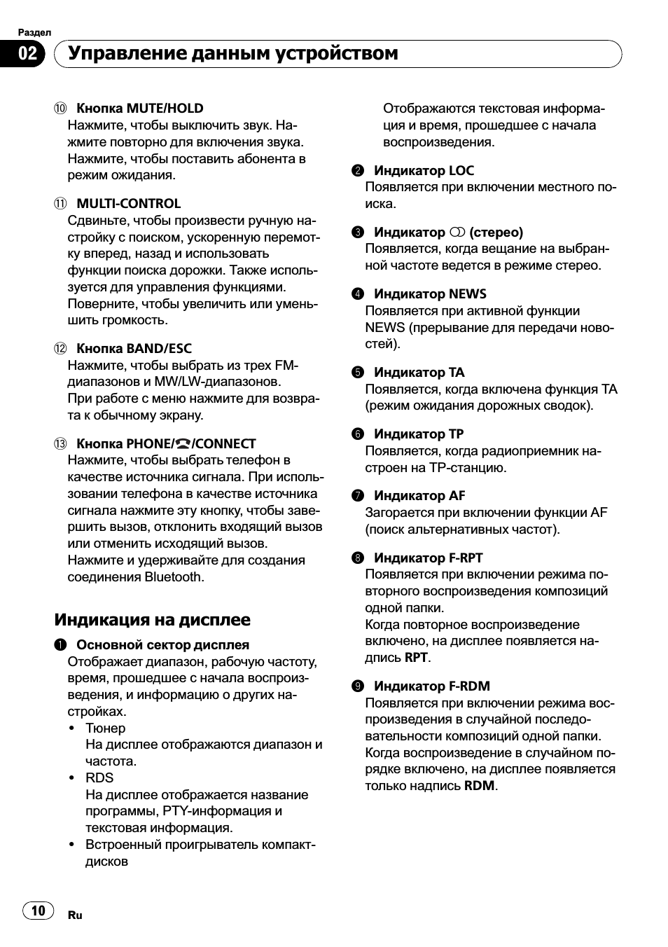
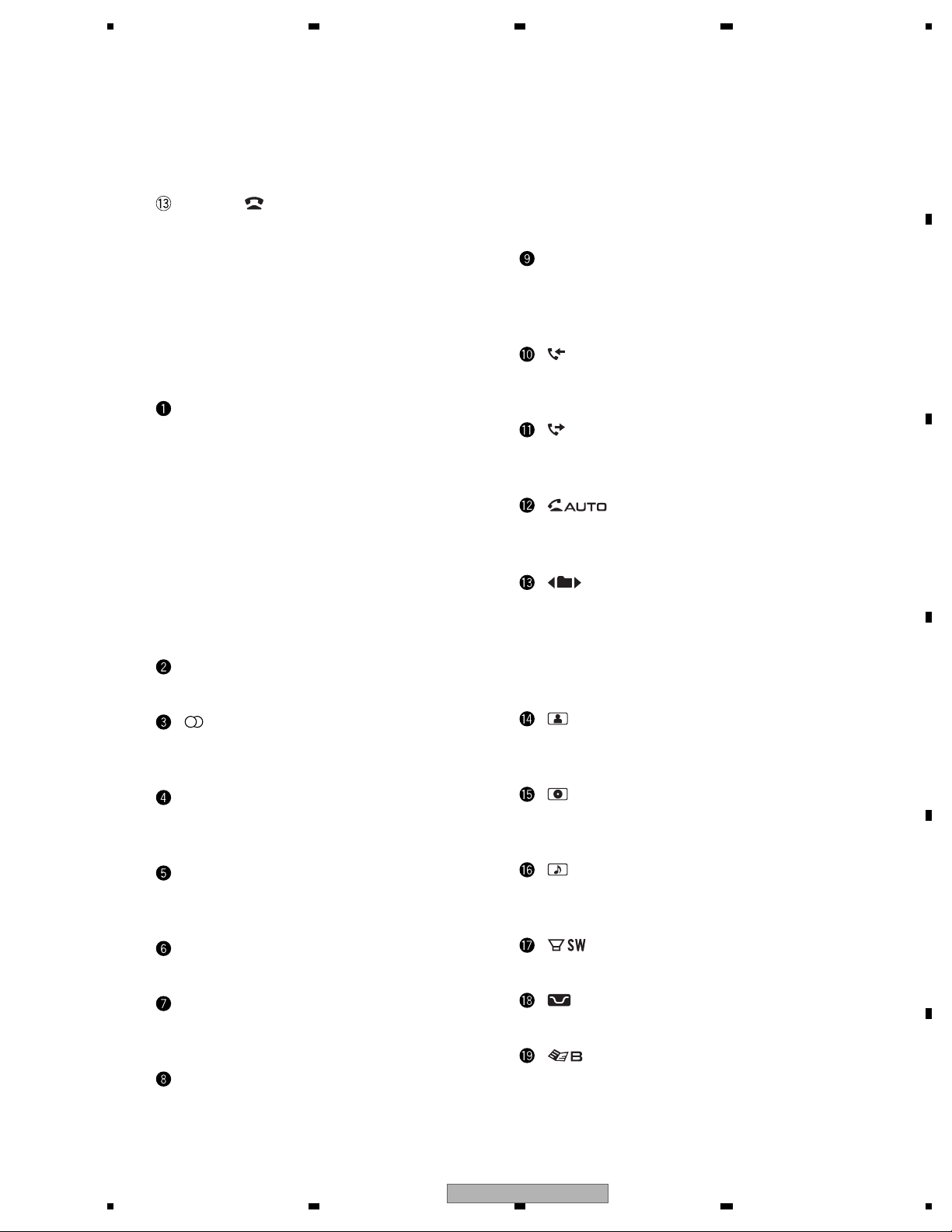
a Кнопка MUTE/HOLD
Нажмите, чтобы выключить звук. На-
жмите повторно для включения звука.
Нажмите, чтобы поставить абонента в
режим ожидания.
b MULTI-CONTROL
Сдвиньте, чтобы произвести ручнуюна-
стройку с поиском, ускореннуюперемот-
ку вперед, назад и использовать
функции поиска дорожки. Также исполь-
зуется для управления функциями.
Поверните, чтобы увеличить или умень-
шить громкость.
c Кнопка BAND/ESC
Нажмите, чтобы выбрать из трех FM-
диапазонов и MW/LW-диапазонов.
При работе с менюнажмите для возвра-
та к обычному экрану.
d Кнопка PHONE/
/CONNECT
Нажмите, чтобы выбрать телефон в
качестве источника сигнала. При исполь-
зовании телефона в качестве источника
сигнала нажмите эту кнопку, чтобы заве-
ршить вызов, отклонить входящий вызов
или отменить исходящий вызов.
Нажмите и удерживайте для создания
соединения Bluetooth.
Индикация на дисплее
1
Основной сектор дисплея
Отображает диапазон, рабочуючастоту,
время, прошедшее с начала воспроиз-
ведения, и информациюо других на-
стройках.
! Тюнер
На дисплее отображаются диапазон и
частота.
! RDS
На дисплее отображается название
программы, PTY-информация и
текстовая информация.
! Встроенный проигрыватель компакт-
дисков
Отображаются текстовая информа-
ция и время, прошедшее с начала
воспроизведения.
2
Индикатор LOC
Появляется при включении местного по-
иска.
3
Индикатор 5 (стерео)
Появляется, когда вещание на выбран-
ной частоте ведется в режиме стерео.
4
Индикатор NEWS
Появляется при активной функции
NEWS (
прерывание для передачи ново-
стей).
5
Индикатор TA
Появляется, когда включена функция TA
(
режим ожидания дорожных сводок).
6
Индикатор TP
Появляется, когда радиоприемник на-
строен на TP-станцию.
7
Индикатор AF
Загорается при включении функции AF
(
поиск альтернативных частот).
8
Индикатор F-RPT
Появляется при включении режима по-
вторного воспроизведения композиций
одной папки.
Когда повторное воспроизведение
включено, на дисплее появляется на-
дпись RPT.
9
Индикатор F-RDM
Появляется при включении режима вос-
произведения в случайной последо-
вательности композиций одной папки.
Когда воспроизведение в случайном по-
рядке включено, на дисплее появляется
только надпись RDM.
Управление данным устройством
Ru
10
Раздел
02
05:20
Автомобильная магнитола Pioneer DEH-S5000BT
19:20
Как выбрать магнитолу Pioneer 2017
14:21
Настройки PIONEER DEH P6000UB
04:01
пионер 65 бт,небольшой обзор музыки в авто
01:23
44 сек.. pioneer deh 600 вт. + саб mp4
15:54
Установка Bluetooth в магнитолу с переключением треков на панели
02:47
Автомагнитолы Pioneer 18+
Нажмите на кнопку для помощи
PIONEER CORPORATION 4-1, Meguro 1-chome, Meguro-ku, Tokyo 153-8654, Japan
PIONEER ELECTRONICS (USA) INC. P.O. Box 1760, Long Beach, CA 90801-1760, U.S.A.
PIONEER EUROPE NV Haven 1087, Keetberglaan 1, 9120 Melsele, Belgium
PIONEER ELECTRONICS ASIACENTRE PTE. LTD. 253 Alexandra Road, #04-01, Singapore 159936
PIONEER CORPORATION 2008
CD RDS RECEIVER
ORDER NO.
CRT4115
DEH-600BT/XN/EW5
DEH-600BT
This service manual should be used together with the following manual(s):
Model No. Order No. Mech.Module Remarks
CX-3195 CRT3815 S10.5COMP2
CD Mech. Module : Circuit Descriptions, Mech. Descriptions, Disassembly
/XN/EW5
For details, refer to «Important Check Points for Good Servicing».
K-ZZY FEB. 2008 Printed in Japan
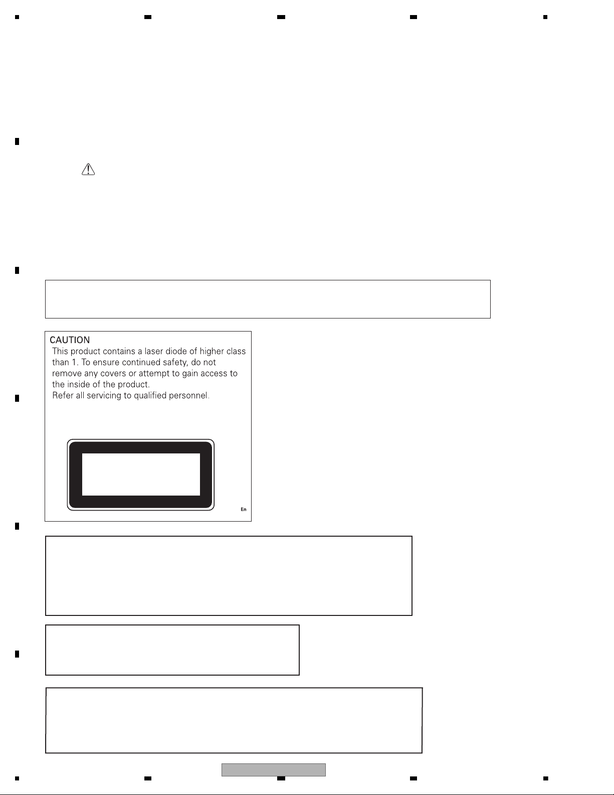
SAFETY INFORMATION
CAUTION:
USE OF CONTROLS OR ADJUSTMENTS OR PERFORMANCE OF PROCEDURES OTHER THAN THOSE
SPECIFIED HEREIN MAY RESULT IN HAZARDOUS RADIATION EXPOSURE.
CLASS 1
LASER PRODUCT
WARNING!
The AEL (accessible emission level )of the laser power output is less than CLASS 1
but the laser component is capable of emitting radiation exceeding the limit for
CLASS 1.
A specially instructed person should do servicing operation of the apparatus.
Laser diode characteristics
Wave length : 785 nm to 814 nm
Maximum output : 1 190 W(Emitting period : unlimited)
Additional Laser Caution
Transistors Q101 in PCB drive the laser diodes.
When Q101 is shorted between their terminals, the laser diodes will radiate beam.
If the top cover is removed with no disc loaded while such short-circuit is continued,
the naked eyes may be exposed to the laser beam.
— Safety Precautions for those who Service this Unit.
When checking or adjusting the emitting power of the laser diode exercise caution in order to get safe, reliable
results.
Caution:
1. During repair or tests, minimum distance of 13 cm from the focus lens must be kept.
2. During repair or tests, do not view laser beam for 10 seconds or longer.
Where in a manufacturer’s service documentation, for example in circuit diagrams or lists
of components, a symbol is used to indicate that a specific component shall be replaced only
by the component specified in that documentation for safety reasons, the following symbol shall
be used:
This service manual is intended for qualified service technicians; it is not meant for the casual do-it-yourselfer.
Qualified technicians have the necessary test equipment and tools, and have been trained to properly and safely
repair complex products such as those covered by this manual.
Improperly performed repairs can adversely affect the safety and reliability of the product and may void the warranty.
If you are not qualified to perform the repair of this product properly and safely, you should not risk trying to do so
and refer the repair to a qualified service technician.
2
DEH-600BT/XN/EW5
[Important Check Points for Good Servicing]
In this manual, procedures that must be performed during repairs are marked with the below symbol.
Please be sure to confirm and follow these procedures.
1. Product safety
Please conform to product regulations (such as safety and radiation regulations), and maintain a safe servicing environment by
following the safety instructions described in this manual.
1 Use specified parts for repair.
Use genuine parts. Be sure to use important parts for safety.
2 Do not perform modifications without proper instructions.
Please follow the specified safety methods when modification(addition/change of parts) is required due to interferences such as
radio/TV interference and foreign noise.
3 Make sure the soldering of repaired locations is properly performed.
When you solder while repairing, please be sure that there are no cold solder and other debris.
Soldering should be finished with the proper quantity. (Refer to the example)
4 Make sure the screws are tightly fastened.
Please be sure that all screws are fastened, and that there are no loose screws.
5 Make sure each connectors are correctly inserted.
Please be sure that all connectors are inserted, and that there are no imperfect insertion.
6 Make sure the wiring cables are set to their original state.
Please replace the wiring and cables to the original state after repairs.
In addition, be sure that there are no pinched wires, etc.
7 Make sure screws and soldering scraps do not remain inside the product.
Please check that neither solder debris nor screws remain inside the product.
8 There should be no semi-broken wires, scratches, melting, etc. on the coating of the power cord.
Damaged power cords may lead to fire accidents, so please be sure that there are no damages.
If you find a damaged power cord, please exchange it with a suitable one.
9 There should be no spark traces or similar marks on the power plug.
When spark traces or similar marks are found on the power supply plug, please check the connection and advise on secure
connections and suitable usage. Please exchange the power cord if necessary.
a Safe environment should be secured during servicing.
When you perform repairs, please pay attention to static electricity, furniture, household articles, etc. in order to prevent injuries.
Please pay attention to your surroundings and repair safely.
2. Adjustments
To keep the original performance of the products, optimum adjustments and confirmation of characteristics within specification.
Adjustments should be performed in accordance with the procedures/instructions described in this manual.
4. Cleaning
For parts that require cleaning, such as optical pickups, tape deck heads, lenses and mirrors used in projection monitors, proper
cleaning should be performed to restore their performances.
3. Lubricants, Glues, and Replacement parts
Use grease and adhesives that are equal to the specified substance.
Make sure the proper amount is applied.
5. Shipping mode and Shipping screws
To protect products from damages or failures during transit, the shipping mode should be set or the shipping screws should be
installed before shipment. Please be sure to follow this method especially if it is specified in this manual.
DEH-600BT/XN/EW5
3

CONTENTS
SAFETY INFORMATION ……………………………………………………………………………………………………………………. 2
1. SERVICE PRECAUTIONS ………………………………………………………………………………………………………………. 5
1.1 SERVICE PRECAUTIONS…………………………………………………………………………………………………………. 5
1.2 NOTES ON SOLDERING ………………………………………………………………………………………………………….. 5
2. SPECIFICATIONS ………………………………………………………………………………………………………………………….. 6
2.1 SPECIFICATIONS…………………………………………………………………………………………………………………….. 6
2.2 DISC/CONTENT FORMAT ………………………………………………………………………………………………………… 7
2.3 PANEL FACILITIES…………………………………………………………………………………………………………………… 8
2.4 CONNECTION DIAGRAM ……………………………………………………………………………………………………….. 11
3. BASIC ITEMS FOR SERVICE………………………………………………………………………………………………………… 12
3.1 CHECK POINTS AFTER SERVICING……………………………………………………………………………………….. 12
3.2 PCB LOCATIONS …………………………………………………………………………………………………………………… 12
3.3 JIGS LIST ……………………………………………………………………………………………………………………………… 13
3.4 CLEANING…………………………………………………………………………………………………………………………….. 13
4. BLOCK DIAGRAM………………………………………………………………………………………………………………………… 14
5. DIAGNOSIS…………………………………………………………………………………………………………………………………. 20
5.1 OPERATIONAL FLOWCHART …………………………………………………………………………………………………. 20
5.2 ERROR CODE LIST……………………………………………………………………………………………………………….. 21
5.3 CONNECTOR FUNCTION DESCRIPTION………………………………………………………………………………… 22
6. SERVICE MODE………………………………………………………………………………………………………………………….. 23
6.1 DISPLAY TEST MODE ……………………………………………………………………………………………………………. 23
6.2 CD TEST MODE…………………………………………………………………………………………………………………….. 24
6.3 BLUETOOTH TEST MODE ……………………………………………………………………………………………………… 26
7. DISASSEMBLY…………………………………………………………………………………………………………………………….. 30
8. EACH SETTING AND ADJUSTMENT …………………………………………………………………………………………….. 36
8.1 CD ADJUSTMENT………………………………………………………………………………………………………………….. 36
8.2 CHECKING THE GRATING AFTER CHANGING THE PICKUP UNIT……………………………………………. 37
8.3 PCL OUTPUT CONFIRMATION……………………………………………………………………………………………….. 39
9. EXPLODED VIEWS AND PARTS LIST……………………………………………………………………………………………. 40
9.1 PACKING ………………………………………………………………………………………………………………………………. 40
9.2 EXTERIOR(1) ………………………………………………………………………………………………………………………… 42
9.3 EXTERIOR(2) ………………………………………………………………………………………………………………………… 44
9.4 CD MECHANISM MODULE……………………………………………………………………………………………………… 46
10. SCHEMATIC DIAGRAM ………………………………………………………………………………………………………………. 48
10.1 OVERALL CONNECTION DIAGRAM(GUIDE PAGE)…………………………………………………………………. 48
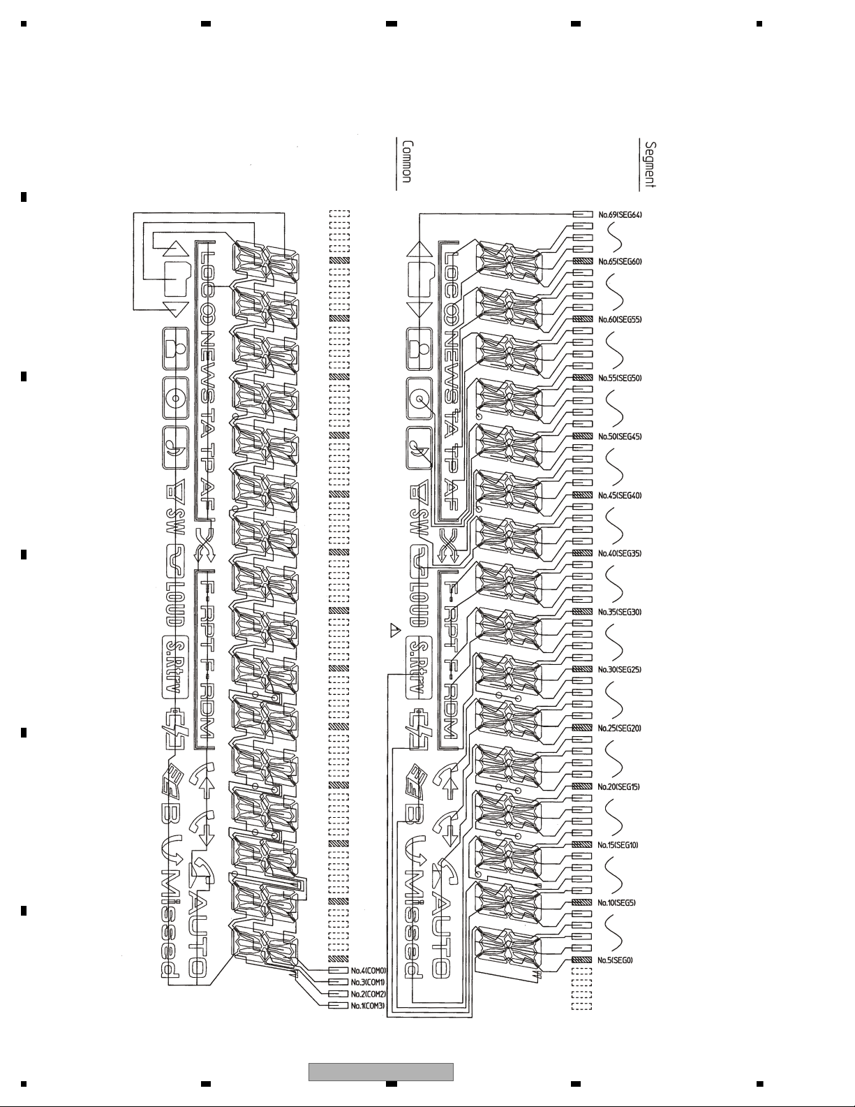
10.2 KEYBOARD UNIT…………………………………………………………………………………………………………………. 54
10.3 CD MECHANISM MODULE(GUIDE PAGE) ……………………………………………………………………………… 56
10.4 BLUETOOTH UNIT / ANTENNA UNIT(GUIDE PAGE) ……………………………………………………………….. 62
10.5 WAVEFORMS………………………………………………………………………………………………………………………. 68
11. PCB CONNECTION DIAGRAM ……………………………………………………………………………………………………. 70
11.1 TUNER AMP UNIT………………………………………………………………………………………………………………… 70
11.2 KEYBOARD UNIT…………………………………………………………………………………………………………………. 74
11.3 CD CORE UNIT(S10.5COMP2)………………………………………………………………………………………………. 76
11.4 BLUETOOTH UNIT ……………………………………………………………………………………………………………….. 78
11.5 ANTENNA UNIT …………………………………………………………………………………………………………………… 80
11.6 PANEL UNIT ………………………………………………………………………………………………………………………… 81
12. ELECTRICAL PARTS LIST ………………………………………………………………………………………………………….. 82
4
DEH-600BT/XN/EW5

1. You should conform to the regulations governing
the product (safety, radio and noise, and other
regulations), and should keep the safety during
servicing by following the safety instructions
described in this manual.
2. Before disassembling the unit, be sure to turn off
the power. Unplugging and plugging the connectors
during power-on mode may damage the ICs inside
the unit.
3. To protect the pickup unit from electrostatic discharge
during servicing, take an appropriate treatment
(shorting-solder) by referring to «the DISASSEMBLY».
4. After replacing the pickup unit, be sure to check the
grating.
5. Be careful in handling ICs. Some ICs such as MOS
type are so fragile that they can be damaged by
electrostatic induction.
For environmental protection, lead-free solder is used on the printed circuit boards mounted in this unit.
Be sure to use lead-free solder and a soldering iron that can meet specifications for use with lead-free solders for repairs
accompanied by reworking of soldering.
Compared with conventional eutectic solders, lead-free solders have higher melting points, by approximately 40 C.
Therefore, for lead-free soldering, the tip temperature of a soldering iron must be set to around 373 C in general, although
the temperature depends on the heat capacity of the PC board on which reworking is required and the weight of the tip of
the soldering iron.
Compared with eutectic solders, lead-free solders have higher bond strengths but slower wetting times and higher melting
temperatures (hard to melt/easy to harden).
The following lead-free solders are available as service parts:
Parts numbers of lead-free solder:
GYP1006 1.0 in dia.
GYP1007 0.6 in dia.
GYP1008 0.3 in dia.
1. SERVICE PRECAUTIONS
1.1 SERVICE PRECAUTIONS
1.2 NOTES ON SOLDERING
DEH-600BT/XN/EW5
5

2. SPECIFICATIONS
General
Power source………………………14.4 V DC (12.0 V to 14.4 V
allowable)
Grounding system…………….. Negative type
Max. current consumption
…………………………………………10.0 A
Dimensions (W × H × D):
DIN
Chassis……………… 178 mm × 50 mm × 162
mm
Nose………………….. 188 mm × 58 mm × 15 mm
D
Chassis……………… 178 mm × 50 mm × 162
mm
Nose…………………… 170 mm × 46 mm × 15 mm
Weight ………………………………. 1.3 kg
Audio
Maximum power output …… 50 W × 4
50 W × 2/4
+ 70 W × 1/2
(for subwoofer)
Continuous power output .. 22 W × 4 (50 Hz to 15000
Hz, 5% THD, 4
load, both
channels driven)
Load impedance ………………. 4
to 8 ×4
4
to 8 ×2+2 ×1
Preout max output level …… 2.2 V
Equalizer (3-Band Parametric Equalizer):
Low
Frequency……………40/80/100/160 Hz
Q Factor …………….. 0.35/0.59/0.95/1.15 (+6 dB
when boosted)
Gain …………………… ±12 dB
Mid
Frequency………….. 200/500/1 k/2 kHz
Q Factor …………….. 0.35/0.59/0.95/1.15 (+6 dB
when boosted)
Gain …………………… ±12 dB
High
Frequency………….. 3.15 k/8 k/10 k/12.5 kHz
Q Factor …………….. 0.35/0.59/0.95/1.15 (+6 dB
when boosted)
Gain ……………………. ±12 dB
HPF:
Frequency…………………..50/63/80/100/125 Hz
Slope…………………………..–12 dB/oct
Subwoofer (mono):
Frequency…………………..50/63/80/100/125 Hz
Slope…………………………..–18 dB/oct
Gain …………………………… +6 dB to –24 dB
Phase …………………………Normal/Reverse
Bass boost:
Gain ……………………………. +12 dB to 0 dB
CD player
System ………………………………. Compact disc audio system
Usable discs …………………….. Compact disc
Signal-to-noise ratio…………. 94 dB (1 kHz) (IEC-A net-
work)
Number of channels ………… 2 (stereo)
MP3 decoding format ……… MPEG-1 & 2 Audio Layer 3
WMA decoding format ……. Ver. 7, 7.1, 8, 9, 10, 11 (2ch
audio)
(Windows Media Player)
WAV signal format ……………. Linear PCM & MS ADPCM
(Non-compressed)
FM tuner
Frequency range………………. 87.5 MHz to 108.0 MHz
Usable sensitivity……………… 8 dB f (0.7 μV/75
, mono,
S/N: 30 dB)
Signal-to-noise ratio…………. 75 dB (IEC-A network)
MW tuner
Frequency range………………. 531 kHz to 1 602 kHz (9 kHz)
Usable sensitivity……………… 18 μV (S/N: 20 dB)
Signal-to-noise ratio…………. 65 dB (IEC-A network)
LW tuner
Frequency range……………… 153 kHz to 281 kHz
Usable sensitivity……………… 30 μV (S/N: 20 dB)
Signal-to-noise ratio…………. 65 dB (IEC-A network)
Bluetooth
Version………………………………. Bluetooth 2.0 certified
Output power ……………………. +4 dBm Max.
(Power class 2)
Note
Specifications and the design are subject to modifications without notice due to improvements.
Backup current
5.0 mA or less
…………………..
2.1 SPECIFICATIONS
6
DEH-600BT/XN/EW5
The Bluetooth word mark and logos are owned by the Bluetooth SIG, Inc.
and any use of such marks by Pioneer Corporation is under license.
Other trademarks and trade names are those of their respective owners.
* Depends on the version of Windows Media Player 11 used to encode WMA file
the noise may appear.
Then, if you update the version, the noise will be solved.
*
2.2 DISC/CONTENT FORMAT
DEH-600BT/XN/EW5
7
2.3 PANEL FACILITIES
What ’s What
Head unit
SRC/OFF button
This unit is turned on by selecting a source.
Press to cycle through all the available
sources.
DISP/SCROLL button
Press to select different displays.
OPEN button
Press to open the front panel.
LIST button
Press to display the track title list, folder list,
file list, preset channel list or phone number
list depending on the source.
COMP/BMX button
Press to turn COMP (compression) and
BMX function on or off.
RDM button
Press to turn random function on or off.
TA/NEWS button
Press to turn TA function on or off. Press
and hold to turn NEWS function on or off.
indicator
Lights up when your Bluetooth audio player
is connected via Bluetooth wireless technology.
• While connecting, this indicator flashes.
indicator
Lights up when your cellular phone is connected via Bluetooth wireless technology.
• While connecting, this indicator flashes.
While phone connection is not completed, this indicator flashes.
MUTE/HOLD button
Press to turn off the sound. To turn on the
sound, press again.
While talking on the phone, press to put the
call on hold.
MULTI-CONTROL
Move to perform manual seek tuning, fast
forward, reverse and track search controls.
Also used for controlling functions.
Turn to increase or decrease the volume.
BAND/ESC button
Press to select among three FM bands and
MW/LW bands.
Press to return to the ordinary display when
operating the menu.
8
DEH-600BT/XN/EW5
PHONE/ /CONNECT button
Press to select the phone as the source.
While operating a phone source, press to
end a call, reject an incoming call or cancel
making a call.
Press and hold to perform Bluetooth connection.
Display indication
Main display section
Displays band, frequency, elapsed playback
time and other settings.
• Tuner
Band and frequency are displayed.
• RDS
Program service name, PTY information
and other literal information are displayed.
• Built-in CD Player
Elapsed playback time and literal information are displayed.
LOC indicator
Appears when local seek tuning is on.
When repeat function is on, only RPT is displayed.
F-RDM indicator
Appears when folder random is on.
When random function is on, only RDM is
displayed.
(received call) indicator
Appears when received call list is displayed
while telephone source is being selected.
(dialled call) indicator
Appears when dialled call list is displayed
while telephone source is being selected.
(auto answer) indicator
Shows when the automatic answering function is on.
(folder) indicator
Appears when operating list function.
When an upper tier of folder or file exists, c
appears.
When a lower tier of folder or file exists, d
appears.
(stereo) indicator
Appears when the selected frequency is
being broadcast in stereo.
NEWS indicator
Appears when NEWS (news program interruption) function is on.
TA indicator
Appears when TA (traffic announcement
standby) function is on.
TP indicator
Appears when a TP station is tuned in.
AF indicator
Appears when AF (alternative frequencies
search) function is on.
F-RPT indicator
Appears when folder repeat is on.
(artist) indicator
Appears when the disc (track) artist name is
displayed on the main display section.
(disc) indicator
Appears when the disc (album) name is displayed on the main display section.
(song) indicator
Appears when the track (song) name is displayed on the main display section.
(subwoofer) indicator
Appears when subwoofer is on.
(loudness) indicator
Appears when loudness is on.
(phone book) indicator
Appears when phone book list is displayed
while telephone source is being selected.
DEH-600BT/XN/EW5
9
(missed call) indicator
Appears when there are missed call log.
Appears when missed call list is displayed
while telephone source is being selected.
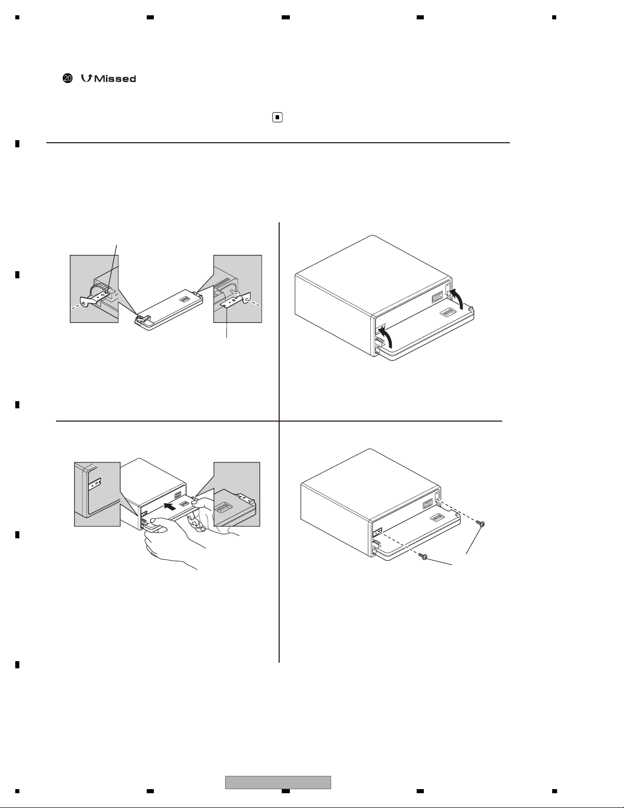
Fastening the front panel
If you do not plan to detach the front panel,
the front panel can be fastened with supplied
screws and holders.
Holder(R)
CND1250
Holder(L)
CND2699
13
24
Screw
BPZ20P060FTB
1. Attach the holders to both sides of the
front panel.
2. Replace the front panel to the unit.
3. Flip the holders into upright
positions.
4. Fix the front panel to the unit using
screws.
10
DEH-600BT/XN/EW5
15 cm
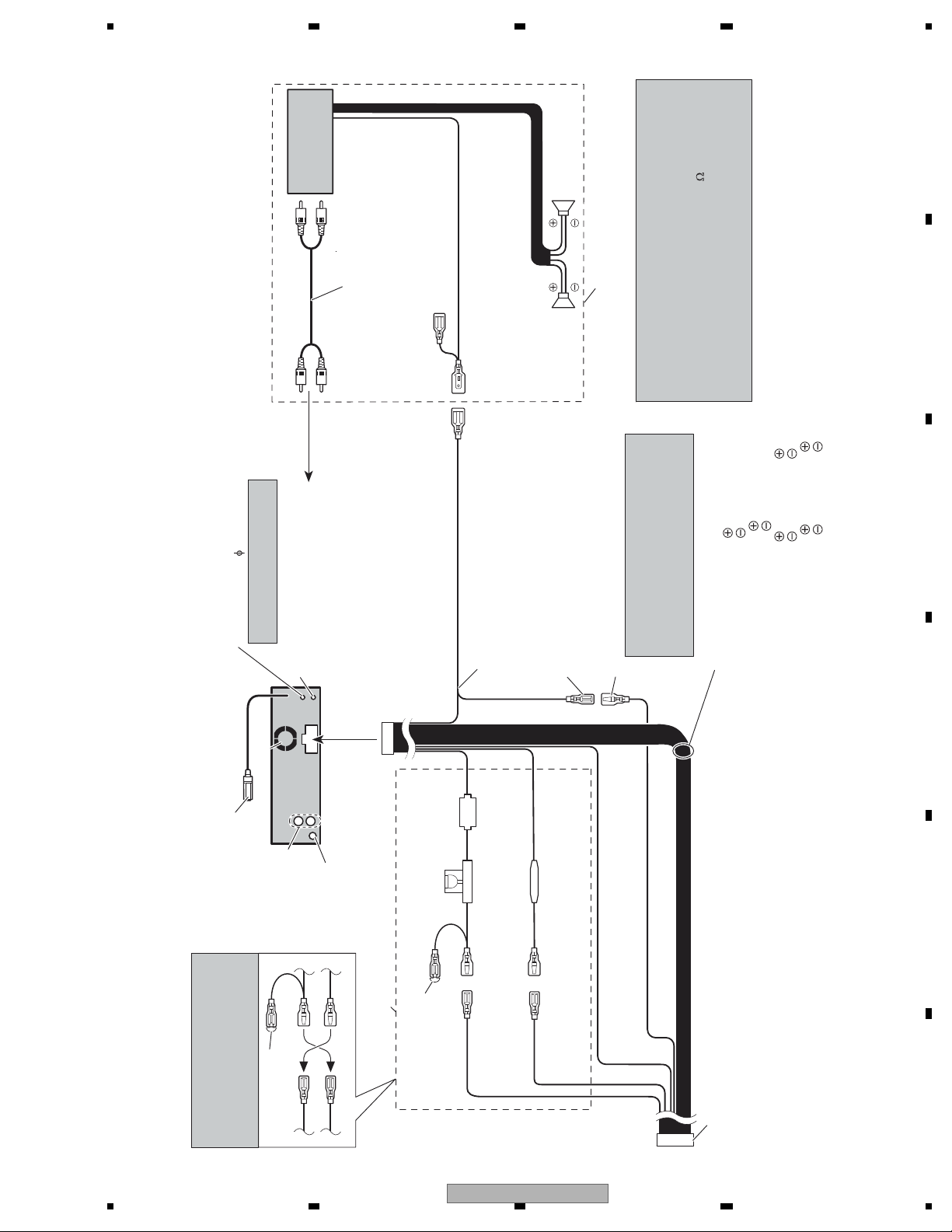
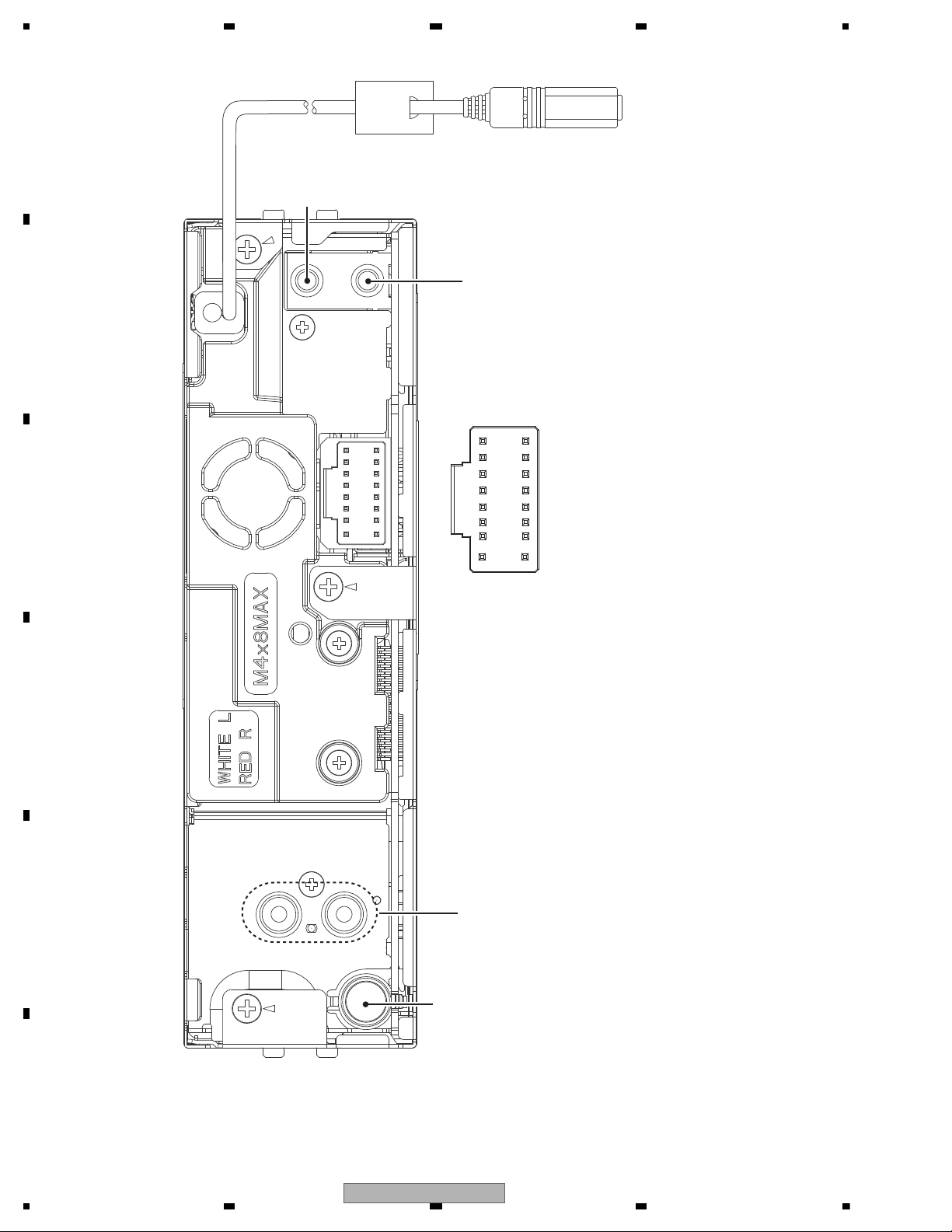
4. Wired remote input
Hard-wired rremote control
adaptor can be connected
(sold separately).
Use a stereo mini plug cable
to connect with auxiliary device.
5. AUX jack (3.5
3. Antenna jack
6. This product
1*
3* 2*
4*5*
7. Note
Depending on the kind of vehicle,
the function of 3* and 5* may be
different. In this case, be sure to
connect 2* to 5* and 4* to 3*.
8. Connect leads of the
same color to each other.
9. Cap (1*)
Do not remove cap
if this terminal is
not in use.
11. Yellow (3*)
Back-up (or
accessory)
14. Red (5*)
Accessory
(or back-up)
12. Yellow (2*)
Connect to the constant 12 V supply
terminal.
15. Red (4*)
Connect to terminal controlled by
ignition switch (12 V DC).
17. ISO connector
Note
In some vehicles, the ISO connector
may be divided into two. In this case,
be sure to connect to both connectors.
21. Speaker leads
White:
White/black:
Gray:
Gray/black:
Green:
Green/black:
Violet:
Violet/black:
18. Blue/white
Connect to system control terminal of the
power amp (max. 300 mA 12 V DC).
19. Blue/white (7*)
Connect to auto-antenna relay control
terminal (max. 300 mA 12 V DC).
16. Black (chassis ground)
Connect to a clean, paint-free metal location.
The pin position of the ISO connector will
differ depepends on the type of vehicle.
Connect 6* and 7* when Pin 5 is an
antenna control type. In another type of
vehicle, never connect 6* and 7*.
20. Blue/white (6*)
2. Rear output or
subwoofer output
1. Microphone input
Connect to optional microphone
(CD-VM1).
10. Fuse (10 A)
13. Fuse resister
24. Power amp
(sold separately)
26. Left 27. Right
25. System remote control
)
23. Connect with RCA cables
(sold separately)
29. Perform these connections when
using the optional amplifier.
Front left
Front left
Front right
Front right
Rear left or subwoofer
Rear left or subwoofer
Rear right or subwoofer
Rear right or subwoofer
22.To Rear output or
subwoofer output
28.Rear speaker
or subwoofer
28.Rear speaker
or subwoofer
30. Notes
• Change the initial setting of this unit (refer to the
operation manual). The subwoofer output of this unit is
monaural.
• When using a subwoofer of 70 W (2
), be sure to
connect with Violet and Violet/black leads of this unit.
Do not connect anything with Green and Green/black
leads.
>
2.4 CONNECTION DIAGRAM
DEH-600BT/XN/EW5
11
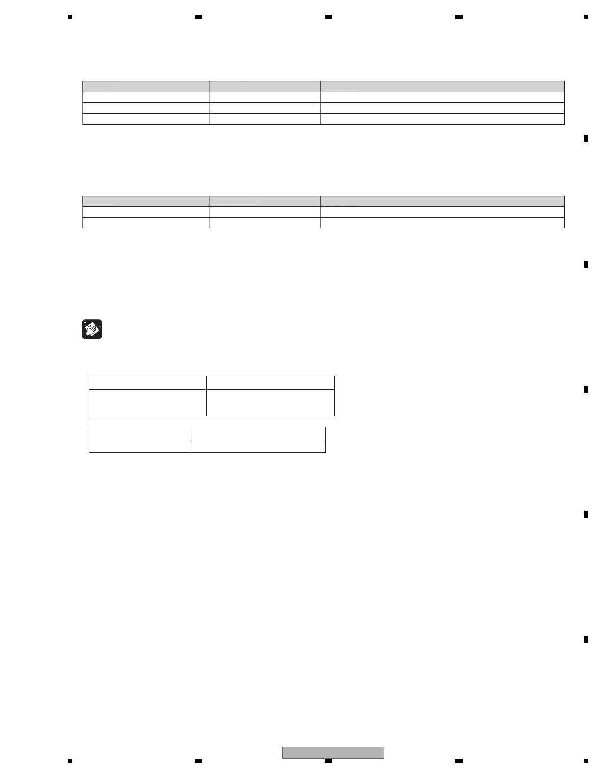
3. BASIC ITEMS FOR SERVICE
demrifnocebotmetIserudecorP.oN
1 Confirm whether the customer complain has
been solved.
If the customer complain occurs with the
specific media, use it for the operation check.
The customer complain must not be
reappeared.
Display, audio and operations must be
normal.
2 CD Play back a CD.
(Track search)
No malfunction on display, audio and
operation.
3 FM/AM tuner Check FM/AM tuner action.
(Seek, Preset)
Switch band to check both FM and AM.
Display, audio and operations must be
normal.
4 Check whether no disc is inside the product. The media used for the operating check must
be ejected.
retfaecnaraeppastinotridrosehctarcsoNkcehcecnaraeppA5
receiving it for service.
Item to be checked regarding audio
Display, audio and operations must be normal.
A
B
Keyboard Unit
E
Antenna Unit
D
Bluetooth Unit
C
Tuner Amp Unit
F
Panel Unit
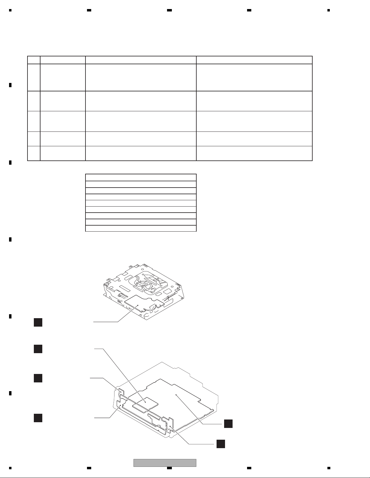
CD Core Unit
(S10.5COMP2)
Unit Number : CWN3281
Unit Name : Tuner Amp Unit
Unit Number :
Unit Name : Keyboard Unit
Unit Number : CXK5763
Unit Name : CD Core Unit
(S10.5COMP2)
Unit Number : CWN3394
Unit Name : Bluetooth Unit
Unit Number : CWN2338
Unit Name : Antenna Unit
Unit Number : CWN3286
Unit Name : Panel Unit
3.1 CHECK POINTS AFTER SERVICING
To keep the product quality after servicing, please confirm following check points.
See the table below for the items to be checked regarding audio:
Distortion
Noise
Volume too low
Volume too high
Volume fluctuating
Sound interrupted
3.2 PCB LOCATIONS
12
DEH-600BT/XN/EW5
— Jigs List
Name
Test Disc
L.P.F.
Jig No.
TCD-782
GGF1539
Remarks
Checking the grating
Checking the grating (Two pieces)
Removing the cord assy (BT antenna cable)
— Grease List
Name
Grease
Grease
Grease No.
GEM1024
GEM1045
Remarks
CD Mechanism Module
CD Mechanism Module
Before shipping out the product, be sure to clean the
following portions by using the prescribed cleaning
tools:
Portions to be cleaned Cleaning tools
CD pickup lenses Cleaning liquid : GEM1004
Cleaning paper : GED-008
Portions to be cleaned Cleaning tools
Fans Cleaning paper : GED-008
3.3 JIGS LIST
m
3.4 CLEANING
No.
rease No.
emarks
emarks
DEH-600BT/XN/EW5
13
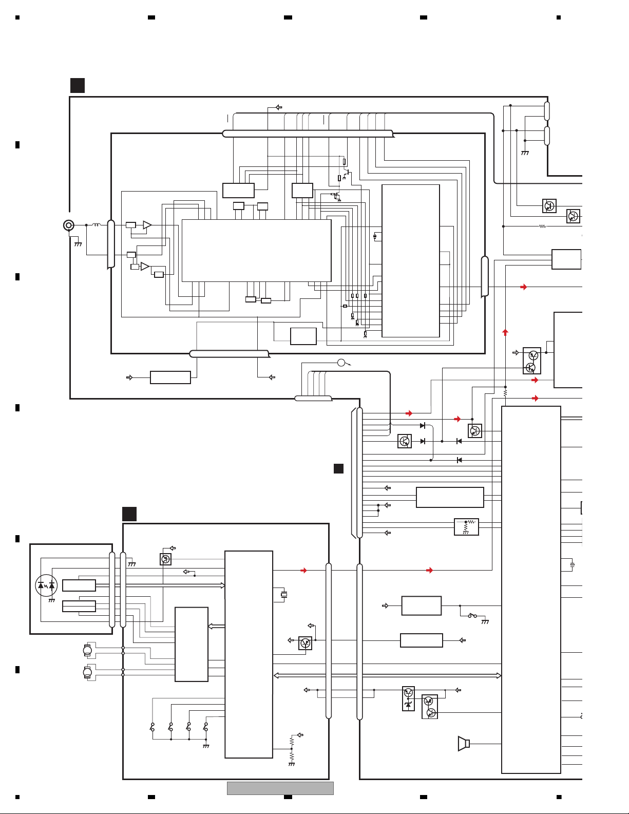
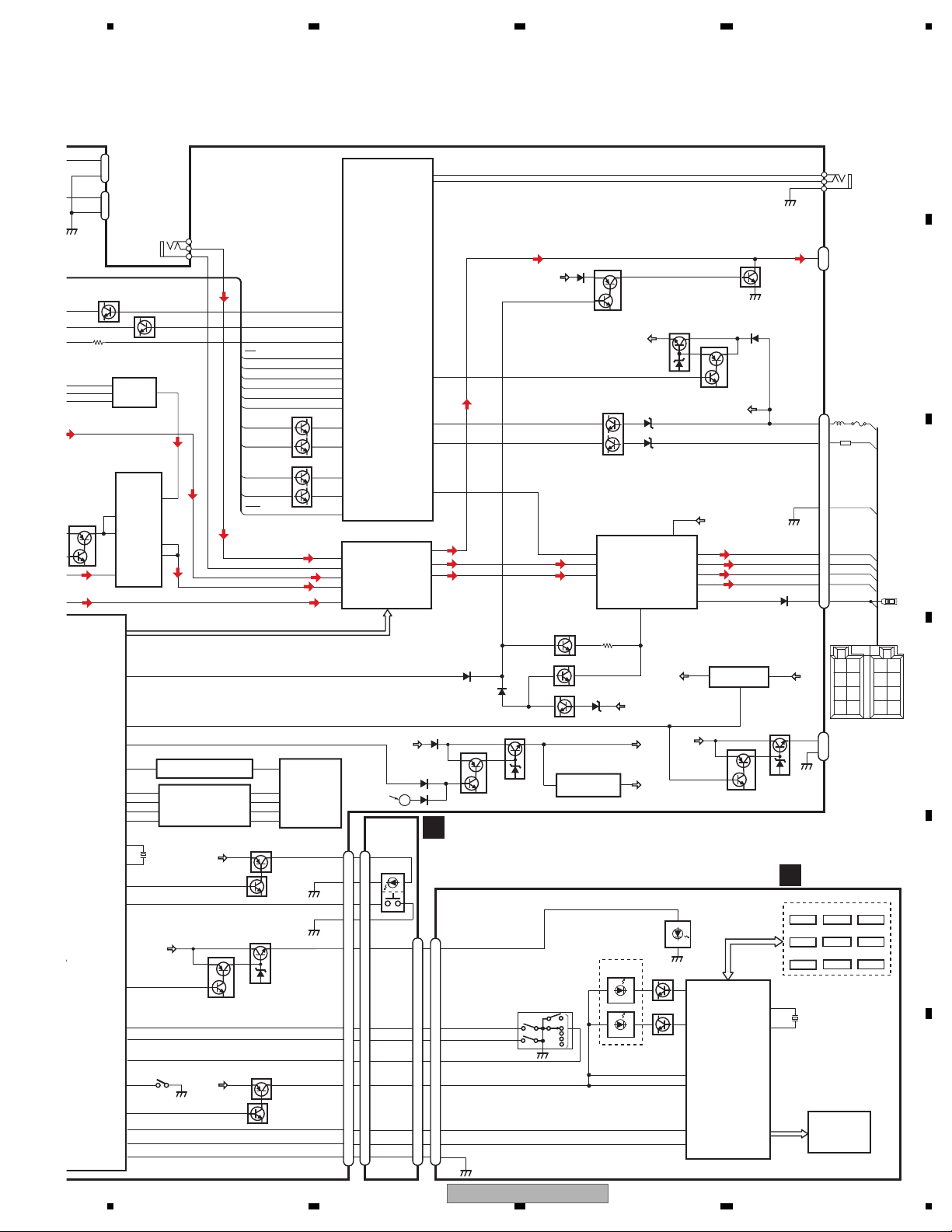
4. BLOCK DIAGRAM
3V -> 5V
LOUT
MUTE
BTPW
XIN
XOUT
SYSTEM
CONTROLLER
IC601(1/2)
PEG442B8
MUTE
JA401
TUNER3V REG
1
2,3
JA1
CN984
TUNER AMP UNIT
1
64
85
SYSPW
A
AUX
14
15
3
4
A8V
A8V
VDD
ANTENNA
59
FLPILM
BRST,BRXEN,BSRQ,BDATA,BSCK
VDD
VDD
MEMDI
4
MEMWP
43
MEMDO
3
MEMCK
5
MEMCS
42
1
3
12
9
4
CONTTEL
BTMUTE
BTCTS
BTRX
BTTX
BTRTS
PEE
RESET
BTRST
BTTEST
TELBEEP
13
X
20.0
11
CE2
SL
CK
CE1
LDET
DI
DO
Q252
Q562
1
2
3
61
34
33
68
53
66
65
63
22
15
17
32
6
5
9
IC501(1/2)
TC74VHCT08AFTS1
5V -> 3V
BTRTS3
BTTX3
BTRX3
BTCTS3
MICIN
TELOUT
HFAV
BTRST
BTTEST
9
3A 3Y
4Y4A
8
12
11
7
26
10
18
8
RESET
92
VDCONT
CDRST
CN552
40
34
33
35
54
55
56
DACCK
DACDT
DACCS
DACCS
DACDT
DACCK
24
36
BOOTE
AVL
8
OTX
39
BT3V
11
BT5V
IC251
TC4066BFT
12
13
CONT1
CONT4
OUT/IN3
OUT/IN4
IN/OUT4
40
ORX ORST
BOOTE
ORST
OTX
ORX
54
2
1
6
BTPW2
CN561
REAR
MIC
CN551
SELECTOR
MUTE
Q561
IN/OUT3
8
12
A8V
10
D
CN76
Q251
A8V
BZ601
BUZZER
RESET
1
2
IC651
S-80835CNMC
-B8U
CD3.3V REG
MECHA VD
1
3
IC701
NJM2885DL1-33
Q751
Q752
BUP
S651
A
EJTIN
6
2
7
PHONE MIXING
IC561
NJM4558MD
IN-2
OUT1
IN-1
OUT2
IC431
NJM2885DL1-33
1
3
VDD
VD
2
1
MUTE
Q563
JOYST
DPDT
KYDT
CSENS
ROT1
91
30
29
58
38
90
37
36
ROT0
ILMPW
DSENS
SWVDD
S
35
BU
CN562
FRONT
MIC
2
1
PICKUP UNIT
(P10.5)(SERVICE)
CD CORE UNIT(S10.5COMP2)
C
BRST,BRXEN,BSRQ
CN701
Q101
M
LASER
DIODE
MONITOR
DIODE
S903
DSCSNS
SPINDLE
MOTOR
M
CARRIAGE
MOTOR
LOAD/
LD-
MD
15
5
HOLOGRAM
UNIT
IC301
BA5839FP
IC201
PE5547A
RF-AMP, CD DECODER,
MP3/WMA DECODER,
DIGITAL SERVO /
DATA PROCESSOR
CD
DRIVER
2
VD
VD
13
LOUT
CN101
16
SOP
15
SOM
18
LCOP
17
LCOM
21
CLCONT
55
LOUT
9
CONT
TD,FD
AC,BD,F,E
SD,MD
S901
HOME
S904
12EJ
S905
8EJ
LD+
14
141
LD
142
PD
12EJ
CONT
CLCONT
HOME
8
9
43
41
1
VDD
BDATA,BSCK
15
5
FOCUS ACT.
TRACKING ACT.
FOP
TOP
2
1
TOP
FOP
11
FOP
14
TOP
2
1
14
8EJ
7
DSCSNS
6
9
VDD
Q102
39
/PUEN
VDD
VCC
16
/RESET
8
/RESET
88
VREF
REFO
133
REFOUT
33
FOM
FOM
12
FOM
44
TOM
TOM
13
TOM
22
LOEJ
LOEJ
5
52
50
X201
XTAL
/XTAL
16.93MHz
VDSENS
11
VD
FMRF
ANT adj
RF adj
FM ANT
T51
CF52
RFGND
VDD_3.3
OSCGND
DGND
AUDIOGNDNCVCC
3.3V
2.5V
IC 4
3.3V -> 2.5V
IC 2
2.5V
NC
CE2
ROM_VDD
SL
DI
CK
CE1
LDET
DO
RDS_CK
RDS_DATA
RDS_LOCK
RDS_HSLK
76 13 5 1098 11 14 18192021
1
3
217 12 15 22 16 4
IC 1
3.3V
AM ANT
FMRF
FM/AM TUNER UNIT
ATT
LPF
OSC
IC 3 EEPROM
5.0V
IC 5
5V -> 3.3V
ATT
MIXER, IF AMP
DET, FM MPX,
RDS DECODER
23
Lch
Firmware rewriting
connector for Bluetooth
14
DEH-600BT/XN/EW5
BSENS
ASENS
BUP
72
73
DALMON
67
10
Pre/SW_L
11
Rear_L
MUTE
BTPW
XIN
XOUT
5
3
21
23
OUT2+
OUT2-
OUT4+
OUT4-
ACC1
IN2_L
6
1
2
IN3_L
IN5-_L
IN5+L
IN1_L
7
45
81
IN2(FL)
STBY
12
4
IN4(RL)
14
22
IC201
PML018A
AMP
IC351
PAL007C
VDD
Q901
Q921
SYSPW
JA151(1/2)
BTMUTE3
BTMUTE2
TELBEEP2
ELECTRONIC VOLUME/
SOURCE SELECTOR
MUTE
VST,VCK,VDT
TUNL
AUXG
AUXL
CDL
A8V
BUP
BT3V
BT5V
1
64
85
SYSPW
Q383
Q402
Q401
MUTE
SWL
Q303
12
Front-L
AMPPW
49
25
Switch_out
VDD
BSENS
ASENS
SYS+B
5
10
12
11
9
1
4
2
CN981
AUX
SL
TUNPCE1
TUNPDO
TUNPDI
95
69
24
70
47
46
TUNPCK
48
CE1
DO
DI
CK
Q902
KEYD
2
KEYAD
89
BUP
6,20
Q381
SWL
EJSW
FLPILM
59
FLPILM
MEMORY
3V -> 5V
5V -> 3V
CN331
RCA OUT
RL2
RL1
FL2
FL1
GND1
BRE1
MEMDI
4
MEMWP
43
MEMDO
3
MEMCK
5
MEMCS
42
1
3
12
9
4
3
11
8
6
8
5
1
2
4
1
TUNPCE2
CE2
BUP
1
3
2
1
IC911
NJM2388F84
IC461
NJM2885DL1-33
4
SL
RCK
16
RDS_CK
RDSLK
82
RDS_LOCK
RDS57K
83
RDS_DATA
RDT
84
RDS_HSLK
LDET
17
LDET
CS#
SO
1Y
2A
1A
4A
3A 3Y
4Y
1Y
2Y
1A
WP#
SI
SCK
BT3V REG
13
X601
20.000MHz
11
5
2
IC501(2/2)
TC74VHCT08AFTS1
IC521
TC74VHC08FTS1
IC541
LE25FW
203PATT
BUP1
KEYD
KEYAD
6
5
4
Q304
BUP
FLPILM
Q832
BUP
40
Q831
BUP
Q891
Q892
FAN REG
CN891
2
1
FAN
Q382
10
9
IC251
TC4066BFT
12
13
CONT1
CONT4
OUT/IN3
OUT/IN4
IN/OUT4
CN561
REAR
MIC
SELECTOR
MUTE
Q561
IN/OUT3
8
SYSTEM
CONTROLLER
IC601(2/2)
PEG442B8
VCC1,VCC2
ACC
RL-
RL+
FL-
FL+
B.REM
SOUTL
Q251
A
CN1971
CN801
CN1972
PANEL UNIT
F
8
S1970
9
5
1
EJTIN
BT+B
BUP
Q451
Q452
3
2
1
WIRED
REMOTE
1
11
6
2
7
PHONE MIXING
IC561
NJM4558MD
IN-2
OUT1
IN-1
OUT2
2
1
MUTE
Q563
JA151(2/2)
8
9
5
1
JOYST
DPDT
KYDT
CSENS
ROT1
CSENS
91
KYDT
30
DPDT
SW5V
29
58
38
JOYST
90
ROT1
37
ROT0
36
ROT0
ILMPW
DSENS
SWVDD
2
ILM+B
SWVDD
VDD
Q842
Q841
10
13
12
5
9
7
11
10
14
8
6
11
2
4
3
S801
IL+B
35
BUP
Q823
Q821
10
13
12
11
14
6
2
4
CN562
FRONT
MIC
2
1
GND
ROTARY
COMMANDER
S1110
IL+B
SWVDD
LCD DRIVER/
KEY CONTROLLER
IC1101
PD6538A
8
10
2
CN1101
3
DPDT
KYDT
50
49
RXD
TXD
10
1
Phase_A
Phase_B
X0
X1
54
X1101
5MHz
55
5
46
47
48
59
V3
VCC
ROUT1
ROUT3
CSENS
JOYST
KEY MATRIX
S1106
S1104 S1105
S1108
TA
S1109
LIST
S1107
S1102
S1103
S1101
D1104
Q1101
Q1102
BAND
SRC
PHONE
DISP
MUTE
RDM
COMP
KST1-3,KDT1-3
LCD
ROT0
ROT1
6
4
11
ILLUMI
D1105-D1115
ILLUMI
D1103
KEYBOARD UNIT
B
RR
+
RR
FR
+
FR
FL
+
FL
RL
+
RL
—
ACC
GND
ANT
BACK
UP
B.UP
CEK1136
10A
>
1k(1/2W)
DEH-600BT/XN/EW5
15
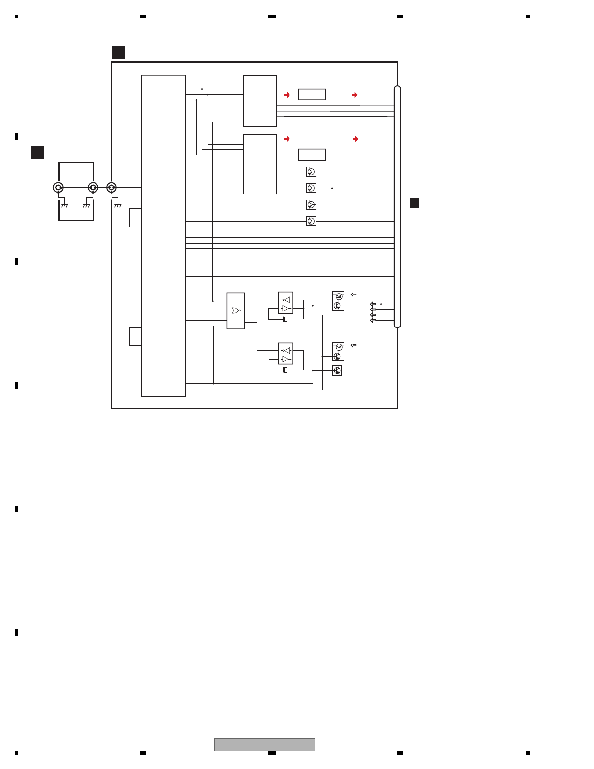
D
BLUETOOTH UNIT
BLUETOOTH MODULE
E
ANTENNA UNIT
ANTENNA
ANT1102
ANT1101
CN1
1
A5
2,3
G9
G8
L9
L8
CWX3619
RF_I/O
VCC_RF
REG_OUT
SCO_CLK_OUT
EXTAL
BRCLK
SIOF_TXD
SIOF_SCK
SIOF_SYNC
Y1
SIOF_RXD
RESETP
SIOF_SS2
SCIF1_CTS
SCIF1_RTS
SCIF1_RXD
SCIF1_TXD
SCIF0_RXD
SCIF0_TXD
BOOT_E
SCIF0_CTS
SCIF0_RTS
SIOF_MCLK
SIOF_SS1
PTB1
N2
Q2
P1
I1
I2
H2
H3
E2
E3
Q1
F1
F2
O1
L1
O3
T3
MCK
HFMCK
HFAV
DATAO
BCK
LRCK
MCK
DATAI
CLOCK SELECT
TC74VHC02FTS1
4
2
3
IC21
2Y
1A
1B
PCM1742KE
2N3
DATA
1N1
BCKIN
3O2
LRCKIN
16
MCLK
3
BCLK
4
DR
5
FS
2
DX
11
4A
12
4B
DAC
IC56
CODEC
IC36
AK2301A
MUTEN
VoutL
13
MD
14
MC
15
ML
7
GSR
15
VFTN
23
22
RSTN
OSC
IC22
TC7PAU04FU
6
3
X21 11.2896 MHz
OSC
IC23
TC7PAU04FU
6
3
X22 12.288 MHz
VCC
VCC
37
NJM4558V
5
AN6123MS
5
1
4
5
1
4
HFAV
FSCHG
LPF
IC66
ALC
IC51
Q37
Q36
1,2
3
Q1
CN76
AUDIOL
DACDT
DACCK
DACCS
TELOUT
MICIN
BTMUTE
BTRST
24
33
34
35
15
17
7
6
A
BTRTS
BTCTS
BTTX
BTRX
ORX
OTX
OCTS
ORTS
HFAV
CN552
5
4
3
2
1
40
39
36
38
37
32
8
9
10
11
12
Q2
Q21
Q23
Q22
BT3V
BT3V
BT3V
BTTEST
BOOTE
D3V
D5V
A8V
16
DEH-600BT/XN/EW5
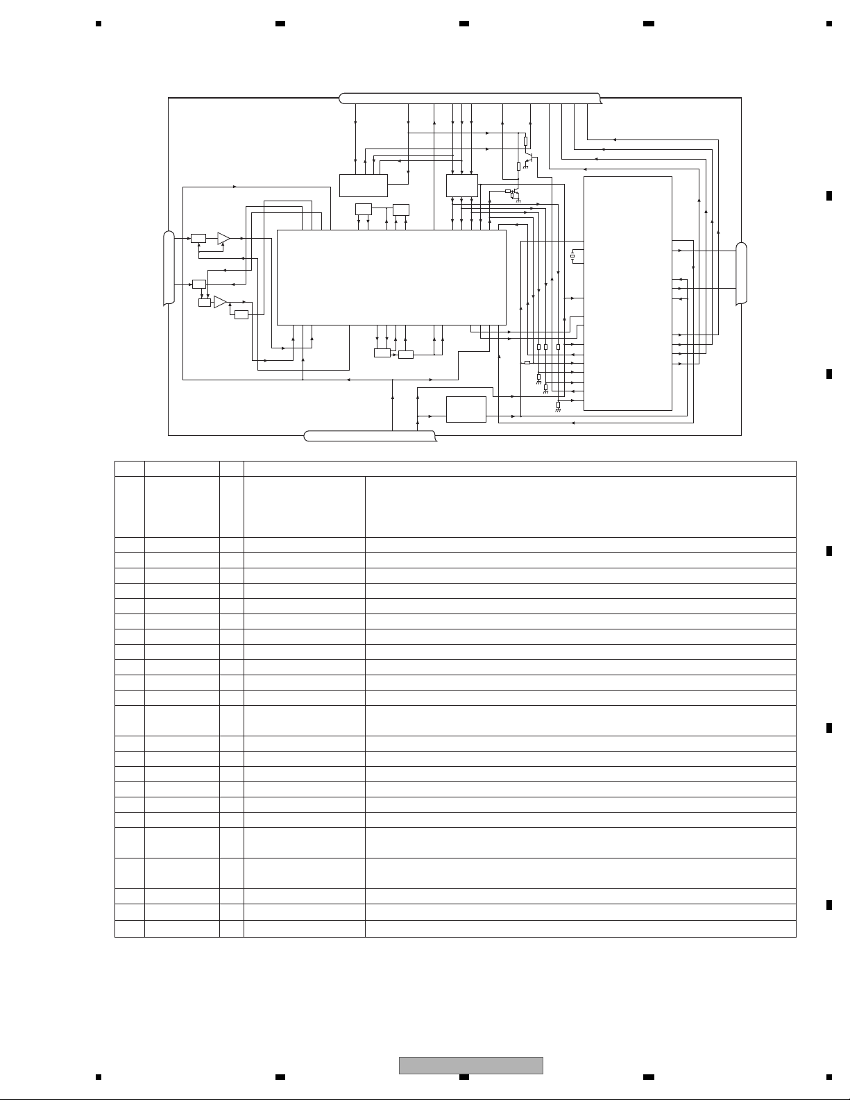
No. Symbol I/O Explain
1 AMANT I AM antenna input AM antenna input high impedance AMANT pin is connected with
an all antenna by way of 4.7 µH. (LAU type inductor) A series circuit
including an inductor and a resistor is connected with RF ground for
the countermeasure against the hum of power transmission line.
2 RFGND RF ground Ground of antenna block
3 FMANT I FM antenna input Input of FM antenna 75 ohm Surge absorber
(DSP-201M-S00B)is necessary.
4 VCC power supply The power supply for analog block. D.C 8.4 V ± 0.3 V
5 SL O signal level Output of FM/AM signals level
6 CE2 I chip enable-2 Chip enable for EEPROM ”Low” active
7 NC non connection Not used
8 CE1 I chip enable-1 Chip enable for AF•RF ”High” active
9 CK I clock Clock
10 DI I data in Data input
11 LDET O lock detector “Low” active
12 OSCGND osc ground Ground of oscillator block
13 ROM_VDD power supply Power supply for EEPROM pin 13 is connected with a power supply of
micro computer.
14 DO O data out Data output
15 DGND digital ground Ground of digital block
16 NC non connection Not used
17 VDD_3.3 power supply The power supply for digital block. 3.3 V ± 0.2 V
18 RDS_CK O RDS clock Output of RDS clock(2.5 V)
19 RDS_DATA O RDS data Output of RDS data(2.5 V)
20 RDS_LOCK O RDS lock Output unit “High” active(2.5 V) (RDS_LOCK turns over by the
external transistor . “Low” active)
21 RDS_HSLK O RDS high speed Output unit “High” active(2.5 V)(RDS_HSLK turns over by the
lock external transistor. “Low” active)
22 AUDIOGND audio ground Ground of audio block
23 L ch O L channel output FM stereo “L-ch” signal output or AM audio output
24 R ch O R channel output FM stereo “R-ch” signal output or AM audio output
FMRF
ANT adj
RF adj
FM ANT
T51
CF52
RFGND
OSCGND
DGND
AUDIOGNDNCVCC
VDD_3.3
3.3 V
2.5 V
IC 4
3.3 V -> 2.5 V
IC 2
2.5 V
NC
CE2
ROM_VDD
SL
DI
CK
CE1
LDET
DO
RDS_CK
RDS_DATA
RDS_LOCK
RDS_HSLK
7 6 13 5 10 9 8 11 14 18 19 20 21
1
3
212 1522 16 4 17
IC 1
3.3 V
AM ANT
FMRF
ATT
LPF
OSC
IC 3 EEPROM
5.0 V
IC 5
5 V -> 3.3 V
ATT
MIXER, IF AM P
DET, FM MPX,
RDS DECODER
24
23
Rch
Lch
FM/AM Tuner Unit
DEH-600BT/XN/EW5
17
18
DEH-600BT/XN/EW5

DEH-600BT/XN/EW5
19

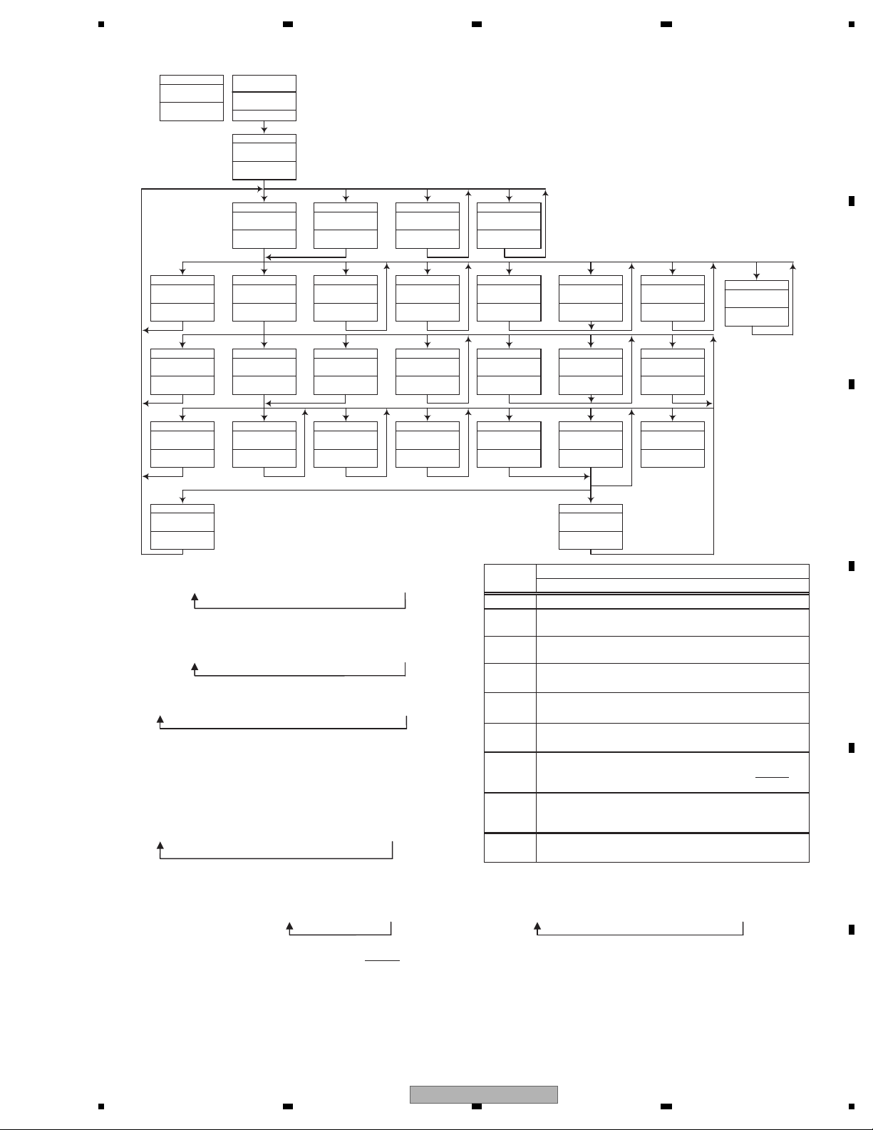
5. DIAGNOSIS
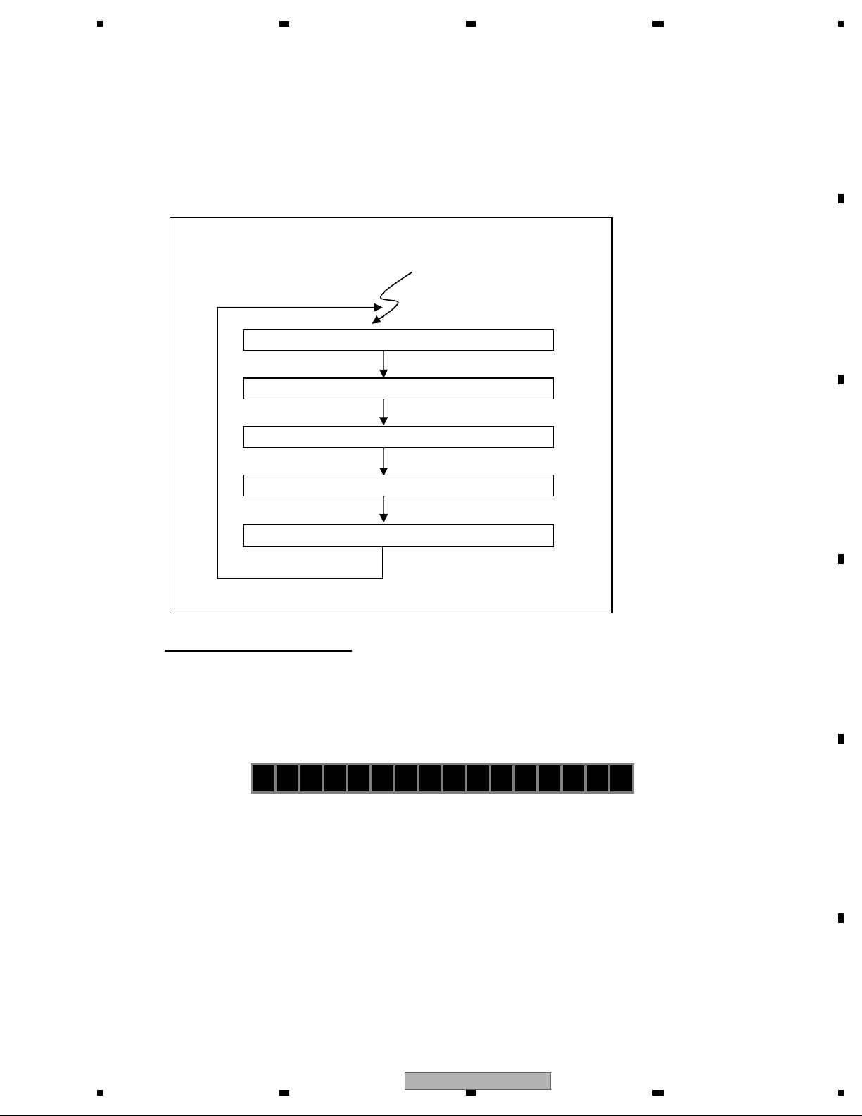
Vcc1 = 5 V
Pin 14
BSENS
Pin 73
ASENS
Pin 72
DSENS
Pin 58
BSENS = L
DSENS = L
Starts
communication
with Grille
microcomputer.
SWVDD <- H
Pin 38
Source keys
operative
Source ON
SYSPW <- H
Pin 1
500 ms
500 ms
Completes power-on operation.
(After that, proceed to each source operation)
In case of the above signal, the communication
with Grille microcomputer may fail.
If the time interval is not 500 msec,
the oscillator may be defective.
Power ON
CSENS
Pin 91
— 2 V < CSENS < 3 V
2 V < CSENS < 3 V
Last source returns.
CD loading functions are available.
Keys except for EJECT key are not available.
ASENS = L
5.1 OPERATIONAL FLOWCHART
20
DEH-600BT/XN/EW5

— Error Messages
If a CD is not operative or stopped during operation due to an error, the error mode is turned on and cause(s) of
the error is indicated with a corresponding number. This arrangement is intended at reducing nonsense calls from
the users and also for facilitating trouble analysis and repair work in servicing.
(1) Basic Indication Method
1) When SERRORM is selected for the CSMOD (CD mode area for the system), error codes are written to DMIN
(minutes display area) and DSEC (seconds display area). The same data is written to DMIN and DSEC. DTNO
remains in blank as before.
2) Head unit display examples
Depending on display capability of LCD used, display will vary as shown below. xx contains the error number.
8-digit display 6-digit display 4-digit display
ERROR-xx ERR-xx E-xx
(2) Error Code List
Code Class Displayed error code Description of the code and potential cause(s)
10 Electricity Carriage Home NG CRG can’t be moved to inner diameter.
SERVO LSI Com- CRG can’t be moved from inner diameter.
munication Error → Failure on home switch or CRG move mechanism.
Communication error between microcomputer and SERVO LSI.
11 Electricity Focus Servo NG Focusing not available.
→ Stains on rear side of disc or excessive vibrations on REWRITABLE.
12 Electricity Spindle Lock NG Spindle not locked. Sub-code is strange (not readable).
Subcode NG → Failure on spindle, stains or damages on disc, or excessive vibrations.
A disc not containing CD-R data is found.
Turned over disc are found, though rarely.
CD signal error.
17 Electricity Setup NG AGC protection doesn’t work. Focus can be easily lost.
→ Damages or stains on disc, or excessive vibrations on REWRITABLE.
30 Electricity Search Time Out Failed to reach target address.
→ CRG tracking error or damages on disc.
44 Electricity ALL Skip Skip setting for all track.
(CD-R/RW)
50
Mechanism
CD On Mech Error Mechanical error during CD ON.
→ Defective loading motor, mechanical lock and mechanical sensor.
A0 System Power Supply NG Power (VD) is ground faulted.
→ Failure on SW transistor or power supply (failure on connector).
Remarks: Mechanical errors are not displayed (because a CD is turned off in these errors).
Unreadable TOC does not constitute an error. An intended operation continues in this case.
Upper digits of an error code are subdivided as shown below:
1x: Setup relevant errors, 3x: Search relevant errors, Ax: Other errors.
Bluetooth audio / telephone
Message
ERROR-10 Built-in Bluetooth Unit
encountered an error
ERROR-80 Built-in FLASH ROM
encountered an error
Cause Factor
Abnormality is found in the line that relates to the communication.
(BTPW, BTRST, BTTEST, BTRX, BTTX, BTRTS and BTCTS)
Defect or breakdown of Bluetooth Unit.
Initial communication on Bluetooth Unit was failed.
•
•
Abnormality is found in the line that relates to the communication.
(BTPW, MEMDI, MEMD0 and MEMCK).
Defect or breakdown of FLASH ROM.
Longevity of FLASH ROM.
Communication on FLASH ROM for phone book was failed.
•
•
•
5.2 ERROR CODE LIST
DEH-600BT/XN/EW5
21
5.3 CONNECTOR FUNCTION DESCRIPTION
1. B.UP
2. GND
3. N.C
4. B.REM
5. ACC
6. N.C
7. N.C
8. N.C
9. RL-
10. FL-
11. RL+
12. FL+
13. RR-
14. FR-
15. RR+
16. FR+
1
357
9
1113 15
2
468
10
1214 16
REAR OUTPUT
or
SUBWOOFER
OUTPUT
AUX INPUT
WIRED REMOTE INPUT
ANTENNA
MIC
22
DEH-600BT/XN/EW5
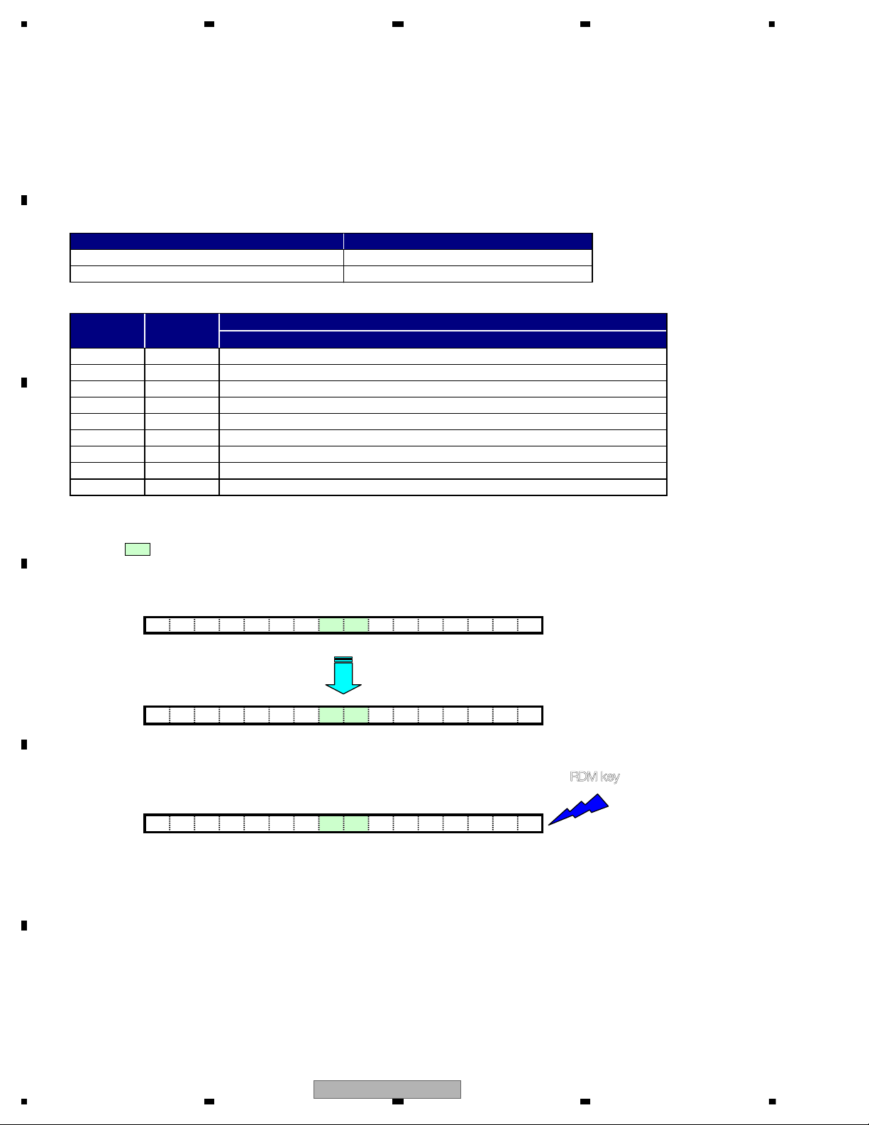
Display test mode
The ACC and back up turn off and turn on while pushing the RDM+COMP key.
To the display test mode.
System version displa
When System version is displayed,
the PD number, the system microcomputer version, and the CWW number is displayed.
Example) For PEG123A VER1.02 CWW1111
The ACC and back up turn off and turn on
while pushing the RDM+COMP key.
Usual display test mode display.
Display test mode all lighting.
RDM+COMP
Display STOP
RDM+COMP
RDM+COMP
ROM Correction version display Ver1.02
System version display Ver1.02
RDM+COMP
RDM+COMP
123A 102 C1111
6. SERVICE MODE
6.1 DISPLAY TEST MODE
DEH-600BT/XN/EW5
23
6.2 CD TEST MODE
To enter the test mode.
While pressing the LIST and RDM keys at the same time, the ACC and back up turn off and turn on.
The specification of the DEH-600BT/XN/EW5 does not include the keys issuance function
for H/U and the remote control unit.
The command issue has achieved the key command transmission by selecting the command.
The outline) The key command selection and the issue at the test mode are done with COMP key and RDM key.
< Table for key >
< Correspondence table of key, command item and command >
Method of issuing key
(The areas below are overwritten and displayed on character strings for the normal mode display.)
1. Key name «K1» is defaulting displayed at the center.
K1 to K9 is switched by the COMP key pressing and the transmitted command is selected.
TR
1 !!!!
COMP Key
TRK! ! K9 !!!!
2. The command has been selected by the RDM key pressing is issued
while displaying the key name of K1 to K9. R
DM key
TRK! ! K9 !!!!
Send a key command selected
by pressing the KEY [6].
RDM ke
Issuing a key command
K2
K3
CRG + / TR Jump + (Direction of the external surface)
CRG — / TR Jump — (Direction of the internal surface
KEY
[BAND]
Command
item
K1
Normal mode
COMP key
Slave Test Mod
Selecting a key command
K4
K5
[ >]
[ <]
[1]
[2]
Focus Close, S.Curve, Measurement of F.EQ / Rough Servo / AGC
Focus Open
Jump Off
K7
K6
K8
Tracking Close / AGC Gain , Display switch of F.Bias adjustment valu
Self adjustment of Tracking Balance / Tracking Open
Operation
Servo Test Mode
Power On/Off
[3]
[4]
[5]
[6]
command DNOCESETUNIMKRT
K9 Switch of Focus Mode / Switch of Tracking Close / CRG.TR Jump
)
24
DEH-600BT/XN/EW5
— Flow Chart
[Key]
Contents
Display
[BAND]
Power Off
TRK MIN SEC
[BAND]
Power Off
TRK MIN SEC
[BAND]
Power Off
TRK MIN SEC
[BAND]
Power Off
TRK MIN SEC
[LIST] + [RDM]
+ BU + ACC
Test Mode In
[CD] or [SOURCE]
Source On
TRK MIN SEC
[BAND]
Power On
(T.Offset is adjusted)
TRK MIN SEC
00 00 00
[3]
Focus Close
S curve check
TRK MIN SEC
91 91 91
[1]
T.Close & AGC
Applicable servomechanism
TRK MIN SEC
?tr ?min ?sec
[1]
F,T,RF AGC
F.Bias display switching
*7
TRK MIN SEC
[3]
Power On
(T.Offset is not adjusted)
TRK MIN SEC
99 99 99
[6]
Focus Mode switching
TRK MIN SEC
[6] [3]
Applicable servomechanism
TRK MIN SEC
[3] [6]
TRK MIN SEC
?tr ?min ?sec
0X 0X 0X
?tr ?min ?sec
F,T AGC / F.Bias
RF AGC
*2
[2]
TRK MIN SEC
GG GG GG
[1]
or 99 99 99
RF AGC coefficient display
TRK MIN SEC
TRK MIN SEC
?tr ?min ?sec
RF AMP
Gain switching
Tracking Servo
Close
00 00 00
RF AGC /
?? ?? ??
CRG/TR jump
value switching
*1
*5
[4]
SPINDLE
Speed switching
TRK MIN SEC
SP SP SP
[>]
CRG +
00 00 00
or 99 99 99
[>]
CRG +
8X 8X 8X
or 9X 9X 9X
[>]
CRG/TR Jump +
*4 *4
TRK MIN SEC
?tr ?min ?sec
*9
[<]
CRG —
00 00 00
or 99 99 99
[<]
CRG —T.Close
8X 8X 8X
or 9X 9X 9X
[<]
CRG/TR Jump —
TRK MIN SEC
?tr ?min ?sec?? ?? ??
[2]
Tracking Open
8X 8X 8X
or 9X 9X 9X
*8
*6
[2]
Self-adjusting
switching
*3*8
TRK MIN SEC
?? ?? ??
[2]
T.Balance adjustment /
T.BAL coefficient display
TRK MIN SEC
?? ?? ??
[2]
Tracking Open
8X 8X 8X
or 9X 9X 9X
[5]
Gop Mode
Gop Mode switching
TRK MIN SEC
OL OL OL
*10
*1) TYP → + 6 dB → + 12 dB
TRK
MIN
SEC
TRK06MIN06SEC
06
TRK12MIN12SEC
12
[Key]
Operation
Test Mode
[BAND] Power On/Off
*2) Focus Close
TRK00MIN00SEC
TRK99MIN99SEC
(
→ S Curve check setting → F EQ measurement setting
00
TRK
MIN01SEC
01
01
TRK02MIN02SEC
02
99)
*3) F.Offset Display → RF.Offset → T.Offset Display → Switch to the
order of the original display
[>]
[<]
[1] T. CLS & AGC & Applicable servomechanism /
[2] RF Gain switching / Offset adjustment display /
CRG + / TR Jump +
(Direction of the external surface)
CRG — / TR Jump (Direction of the internal surface)
AGC,AGC display setting
T.Balance adjustment / T. Open
[3] F. Close,S Curve / Rough Servo and RF AGC /
*4) 1TR/4TR/10TR/32TR/100TR
*5) Single
→ 4TR → 10TR → 32TR → 100TR → CRG Move
9x(8x):91(81) 92(82) 93(83) 94(84) 95(85) 96(86)
*6) Only at the time of CRG move, 100TR jump
*7) TRK/MIN/SEC
→ F.AGC → T.AGC Gain → F.Bias → RF AGC
[4]
[5]
[6] F. Mode switching / Tracking Close / CRG•TR
F,T,RF AGC
SPDL 1X/2X switching
As for the double speed(2x), audio output cannot be
supported.
Error Rate measurement
ON : ERR 30Counts Start
BER display data[%]
Jump Switching
*8) CRG motor voltage = 2 [V]
*9) TYP (1X)
TRK
MIN
SEC
→ 2X → 1X
TRK
MIN22SEC
22
22
TRK11MIN11SEC
11
*10) OFF(TYP)
TRK
MIN
SEC
→ FORCUS → TRACKING
TRK
MIN70SEC
70
70
TRK71MIN71SEC
• As for the double speed (2x), audio output cannot be supported
*) • After the [Eject] key is pressed keys other than the [Eject] key should not be pressed, until disc ejection is complete.
• When the key [2] or [3] is pressed during the Focus Search, the power supply should be immediately turned off (otherwise the lens
sticks to Wall, causing the actuator to be damaged).
• In the case of TR jump other than to 100TR, the function shall continue to be processed even if the TR jump key is released. As for
the CRG Move and 100TR Jump, the mechanism shall be set to the Tracking Close mode when the key is released.
• When the power is turned on/off the jump mode is reset to the Single TR (91) while the gain of the RFAMP is reset to 0 dB. At the
same time all the self-adjusting values shall return to the default setting.
71
DEH-600BT/XN/EW5
25
6.3 BLUETOOTH TEST MODE
When resetting the microprocessor, the memory is initialized except for the following five items.
This enables user to avoid the task of registering phones and transfering phone directory again even after resetting
system at the time of battery exchange, etc.
• phone book entries on the Bluetooth telephone
• preset numbers on the Bluetooth telephone
• registration assignment of Bluetooth telephone
• call history of Bluetooth telephone
• history of the most recently connected Bluetooth audio
— About Memory Clear
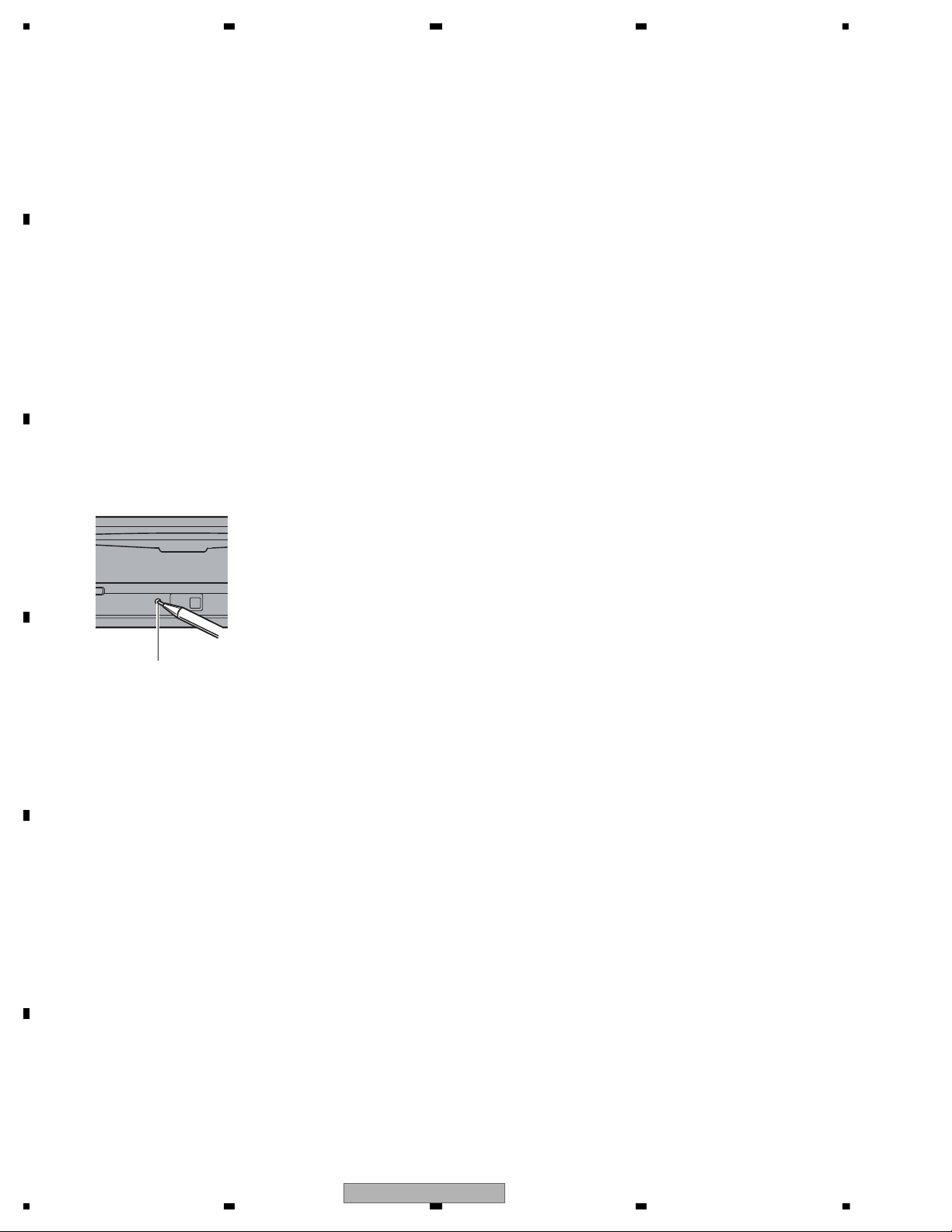
Resetting the microprocessor
The microprocessor must be reset under the
following conditions:
• Prior to using this unit for the first time
after installation
• If the unit fails to operate properly
• When strange or incorrect messages appear on the display
— Press RESET with a pen tip or other
pointed instrument.
RESET button
1 Press SRC and hold until the unit turns off.
2 Press MULTI-CONTROL and hold until
the initial setting menu appears in the display.
3 Turn MULTI-CONTROL to select of
BT RESET:MEMORY .
4 Push MULTI-CONTROL right to show a
confirmation display.
BT RESET:YES is displayed. Clearing memory
is now on standby.
# If you do not want to reset phone memory,
press BAND/ESC.
5 Press MULTI-CONTROL to clear the
memory.
Resetting the Bluetooth
wireless technology module
Bluetooth telephone and Bluetooth Audio
data can be deleted. To protect personal information,
we recommend deleting this data before
transferring the unit to other persons. The
following settings will be deleted.
— phone book entries on the Bluetooth telephone
— preset numbers on the Bluetooth telephone
— registration assignment of Bluetooth telephone
— call history of Bluetooth telephone
— history of the most recently connected
Bluetooth audio
26
DEH-600BT/XN/EW5
— Bluetooth Test Mode (when using BT-compliant mobile phone)
Specifications for BT Built-in mobile phone
The mobile phone compliant to Bluetooth Ver 1.1 requires at least *HFP and *OPP to be mounted.
The model having validly accomplished connecting verification is desirable. [CDMA A5504T(TOSHIBA), 6230(Nokia)etc.)]
The model capable of being in standby state is desirable.
1. Cautions
*These cautions are for the case where mobile phone is actually connected at the service site.
When the mobile phone is actually connected for checking action or the like and the model is registered at the service
site, returning the unit directly to user will leave the telephone information on it which had been registered at the service
site. Thus, in such case, the task to clear only the telephone information used at the service will be required from the
FUNCTION menu.
[Important]
When the mobile phone is actually connected to the registration number of which a user has already registered among
available No.1 through 3 for registration, take note that the telephone information having registered by user will be
overwritten.
2. Outline of Functions
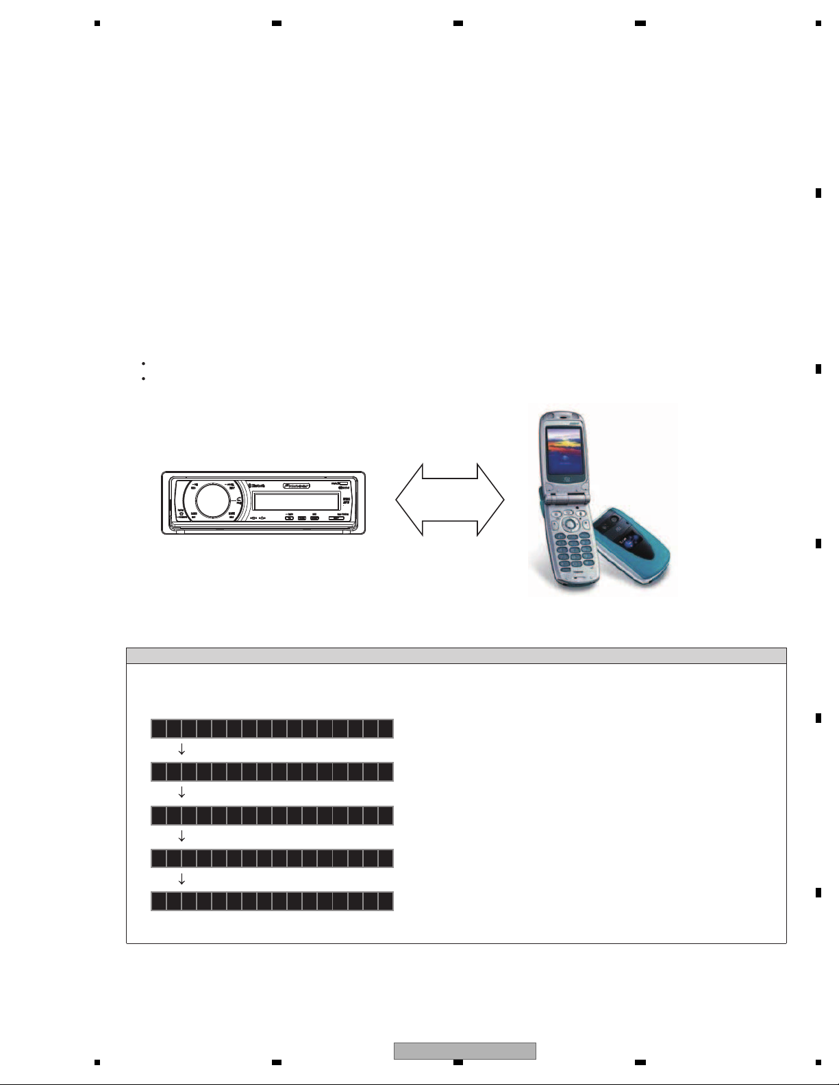
The following 2 items are to be confirmed for the simple BT action check by using BT-compliant mobile phone:
Confirmation of Bluetooth connection (certification connection and voice connection)
Confirmation of BT antenna sensitivity (connection)
3. Configuration Diagram
DEH-600BT
Bluetooth
4. How to Start-up the Test Mode
Specifications for Operation
Operation method
Test mode starts by the ACC and back up turn off and turn on while pressing MUTE+TA keys simultaneously.
AF
Echo cancellation OFF(automatic operation)
0123456789AB
BT equipment call connected
The BD address of the machine is displayed.
(Local address)
AFOTHER
Source change completion(automatic operation)
AFBTTEL
Antenna check end(automatic operation)
A35 F BT TEL
Source name display
Result of Antenna check display
A» : Antenna sensibility value
The value is only a criterion. When the mobile phone
is placed nearest in the front of the product, the value
indicates somewhere between -80 and -18. Other than
this value or the absence of indication refers to the
defective BT antenna connection.
DEH-600BT/XN/EW5
27
Loading…

Раздел
04
Начальные настройки
2 С помощью MULTI-CONTROL вы—
Изменение начальных
берите CLNDR.
настроек
На дисплее появится надпись CLNDR.
1 Нажмите и удерживайте кнопку SRC,
3 Нажимайте MULTI-CONTROL влево
пока устройство не выключится.
или вправо, чтобы выбрать сегмент ди—
2 Нажмите MULTI-CONTROL и удержи—
сплея календаря, который Вы хотите ус—
вайте его до вывода на дисплей исход—
тановить.
ного меню.
День—Месяц—Год
При выборе сегментов дисплея календаря
3 Поверните MULTI-CONTROL, чтобы
выбранный сегмент будет мигать.
выбрать одну из начальных настроек.
CLNDR (календарь)—CLOCK (часы)—
4 Нажмите MULTI-CONTROL вверх или
OFF CLOCK (дежурный режим)—FM STEP
вниз, чтобы задать дату.
(установка шага настройки в FM-диапа—
При нажатии MULTI-CONTROL вверх или
зоне)—AUTO PI (автоматический поиск PI)
вниз происходит увеличение выбранного
—WARNING (предупреждающий сигнал)—
значения дня, месяца или года. При нажа—
AUX (внешний источник сигнала)—
тии MULTI-CONTROL вниз происходит
REAR SP (задний канал и блок управления
уменьшение выбранного значения дня,
сабвуфера)—EVERSCROLL (постоянная
месяца или года.
прокрутка)—TITLE (выбор языка интерфей—
са)—BT AUDIO (Bluetooth аудио)—BT MIC
(настройка микрофона)—PIN CODE INPUT
Установка часов
(ввод PIN-кода)—EDIT DEVICE NAME (из—
Следуйте данным инструкциям для уста—
менение названия устройства)—BT INFO
новки часов.
(номер системной версии Bluetooth)—
BT RESET (сброс настроек Bluetooth)—
1 Выведите на дисплей меню исход—
SOFTWARE UPDATE (обновление про—
ных настроек.
граммного обеспечения)
См.
Изменение начальных настроек
на
# Вы также можете выполнить данную
стр. 48.
операцию, нажимая MULTI-CONTROL вверх
или вниз.
2 С помощью MULTI-CONTROL вы—
# Чтобы отменить начальные настройки, на—
берите CLOCK.
жмите кнопку BAND/ESC.
3 Нажимайте MULTI-CONTROL влево
или вправо, чтобы выбрать сегмент ди—
сплея часов, который Вы хотите устано—
Установка даты
вить.
Дисплей календаря, настроенный в дан—
Часы—Минуты
ном режиме, появляется при выборе
При выборе сегментов дисплея часов вы—
телефона в качестве источника сигнала и
бранный сегмент будет мигать.
отключенном режиме демонстрации функ—
4 Нажмите MULTI-CONTROL вверх или
циональных возможностей.
вниз, чтобы установить показания
1 Выведите на дисплей меню исход—
часов.
ных настроек.
См.
Изменение начальных настроек
на
стр. 48.
48
Ru
Раздел
Начальные настройки
04
1 Выведите на дисплей меню исход—
Примечание
ных настроек.
Вы можете настроить часы по сигналу точного
См.
Изменение начальных настроек
на
времени, нажав MULTI-CONTROL.
стр. 48.
! Если значение находится в пределах от 00
до 29, минуты округляются в меньшую сто—
2 С помощью MULTI-CONTROL вы—
рону.(Например, значение 10:18 станет
берите FM STEP.
Начальные настройки
10:00.)
3 Нажмите MULTI-CONTROL, чтобы вы—
! Если значение находится в пределах от 30
брать шаг настройки в FM-диапазоне.
до 59, минуты округляются в большую сто—
При нажатии MULTI-CONTROL происходит
рону.(Например, значение 10:36 станет
переключение шага настройки в FM-диапа—
11:00.)
зоне между значениями 50 кГц и 100 кГц.
Выбранный шаг настройки в FM-диапазоне
появляется на дисплее.
Включение или выключение
дежурного режима
Примечание
Если включен дисплей дежурного режима,
Во время ручной настройки шаг настройки со—
то при отключении всех источников вход—
ставляет 50 кГц.
ного сигнала и демонстрационного режима
на дисплее будут показаны часы.
Включение
1 Выведите на дисплей меню исход—
ных настроек.
автоматического поиска PI
См.
Изменение начальных настроек
на
Устройство может автоматически искать
стр. 48.
другую станцию с такой же программой
даже во время вызова предварительной
2 С помощью MULTI-CONTROL вы—
настройки.
берите OFF CLOCK.
1 Выведите на дисплей меню исход—
3 Нажмите MULTI-CONTROL, чтобы
ных настроек.
включить дисплей дежурного режима.
См.
Изменение начальных настроек
на
# Нажмите MULTI-CONTROL еще раз, чтобы
стр. 48.
выключить дисплей дежурного режима.
2 С помощью MULTI-CONTROL вы—
берите AUTO PI.
Установка шага настройки
3 Нажмите MULTI-CONTROL, чтобы
в FM-диапазоне
включить автоматический PI поиск (по
Обычно шаг настройки в FM-диапазоне,
идентификатору программы).
используемый при настройке с поиском,
# Нажмите MULTI-CONTROL еще раз, чтобы
составляет 50 кГц. При включении функции
выключить автоматический PI поиск (по иден—
AF или TA шаг настройки автоматически
тификатору программы).
меняется на 100 кГц. При включенной
функции AF предпочтительно установить
шаг настройки 50 кГц.
49
Ru

Раздел
04
Начальные настройки
3 Нажмите MULTI-CONTROL чтобы
Включение
включить AUX.
предупреждающего сигнала
# Чтобы выключить AUX, нажмите
Если не отсоединить переднюю панель от
MULTI-CONTROL еще раз.
основного устройства в течение пяти
секунд после выключения зажигания авто—
мобиля, раздастся предупреждающий сиг—
Установка параметров
нал. Вы можете отключить
выхода заднего канала и
предупреждающий сигнал.
усилителя сабвуфера
1 Выведите на дисплей меню исход—
Выход заднего канала этого устройства
ных настроек.
(выход на провода заднего громкогово—
См.
Изменение начальных настроек
на
рителя и выход заднего канала RCA)
стр. 48.
можно использовать для подключения ши—
2 С помощью MULTI-CONTROL вы—
рокополосного громкоговорителя (FULL)
берите WARNING.
или сабвуфера (SUB W). При выборе для
настройки выхода заднего канала зна—
3 Нажмите MULTI-CONTROL, чтобы
чения SUB W можно подключить провод
включить предупреждающий сигнал.
заднего громкоговорителя непосредствен—
# Чтобы выключить предупреждающий сиг—
но к сабвуферу без использования вспомо—
нал, нажмите MULTI-CONTROL еще раз.
гательного усилителя.
По умолчанию это устройство настроено
на подключение заднего широкополосного
Включение
громкоговорителя (FULL). При подсоедине—
нии выхода заднего канала к широкополос—
вспомогательной настройки
ным громкоговорителям (при выборе FULL)
Вспомогательное оборудование, по—
можно подключить другие широкополос—
дключенное к данному устройству, можно
ные громкоговорители (PREOUT:REAR) или
включать отдельно. При использовании
сабвуфер (PREOUT :SUB W) к выходу за—
входа AUX для каждого источника сигнала
днего канала RCA.
должно быть выбрано положение ON
(ВКЛ). Подробнее о подключении и исполь—
1 Выведите на дисплей меню исход—
зовании вспомогательного оборудования
ных настроек.
см. в
Использование дополнительного ис—
См.
Изменение начальных настроек
на
точника сигнала (AUX)
на стр. 55.
стр. 48.
1 Выведите на дисплей меню исход—
2 С помощью MULTI-CONTROL вы—
ных настроек.
берите REAR SP.
См.
Изменение начальных настроек
на
3 Нажмите MULTI-CONTROL, чтобы
стр. 48.
переключиться в режим настройки вы—
2 С помощью MULTI-CONTROL вы—
хода заднего канала.
берите AUX.
При нажатии MULTI-CONTROL будет вы—
полняться переключение между FULL (ши—
рокополосный громкоговоритель) и SUB W
(сабвуфер) с отображением соот—
ветствующего состояния на дисплее.
50
Ru
Раздел
Начальные настройки
04
# Если сабвуфер не подключен к выходу за—
2 С помощью MULTI-CONTROL вы—
днего канала, выберите FULL (широкополос—
берите EVERSCROLL.
ный громкоговоритель).
3 Нажмите MULTI-CONTROL, чтобы
# Если сабвуфер не подключен к выходу за—
включить функцию постоянной про—
днего канала, выберите SUB W (сабвуфер).
крутки.
# Если для настройки выхода заднего кана—
# Нажмите MULTI-CONTROL еще раз, чтобы
ла выбрано SUB W, выполнить следующую
Начальные настройки
выключить функцию постоянной прокрутки.
процедуру невозможно.
4 Чтобы выбрать выход канала саб—
вуфера или выход заднего канала, на—
Настройка языка
жмите MULTI-CONTROL влево или
На диск, содержащий сжатые аудиофайлы,
вправо.
может быть записана текстовая информа—
При нажатии c или d будет выполняться
ция, например, название композиции, имя
переключение между PREOUT :SUB W и
исполнителя или текстовый комментарий.
PREOUT :REAR с отображением соот—
Это устройство может отображать такую
ветствующего состояния на дисплее.
информацию на русском или любом евро—
пейском языке.
Примечания
! При несовместимости настроек
! Даже при изменении настройки звук вы—
встроенного и выбранного языка воз—
водиться не будет, если Вы не включите
можны искажения при выводе тексто—
выход канала сабвуфера (см.
Использова—
вых сообщений.
ние выхода канала сабвуфера
на стр. 45).
! Некоторые символы могут отображать—
! При изменении данной настройки зна—
ся неправильно.
чение выхода канала сабвуфера в меню
аудионастроек вернется к заводским уста—
1 Выведите на дисплей меню исход—
новкам.
ных настроек.
! В данной настройке параметры выхода ка—
См.
Изменение начальных настроек
на
налов задних громкоговорителей и выхода
стр. 48.
RCA переключаются одновременно.
2 С помощью MULTI-CONTROL вы—
берите TITLE.
Включение режима
3 Нажмите MULTI-CONTROL для выбо—
ра желаемой настройки.
постоянной прокрутки
При нажатии MULTI-CONTROL будет вы—
Если включить функцию постоянной про—
полняться переключение между EURO
крутки, то текстовая информация компакт—
(европейский язык) и RUSSIA (русский
диска будет постоянно прокручиваться на
язык) с отображением соответствующего
дисплее. Отключите этот режим для еди—
состояния на дисплее.
новременной прокрутки этой информации.
1 Выведите на дисплей меню исход—
ных настроек.
См.
Изменение начальных настроек
на
стр. 48.
51
Ru
Перейти к контенту
Автомагнитолы Pioneer
- Размер инструкции: 876.52 kB
- Формат файла: pdf
Если вы потеряли инструкцию от автомагнитолы Pioneer DEH-600BT, можете скачать файл для просмотра на компьютере или печати.
Инструкция для автомагнитолы Pioneer DEH-600BT на русском языке. В руководстве описаны возможности и полезные функции, а также правила эксплуатации. Перед использованием внимательно ознакомьтесь с инструкцией.
Чтобы не читать всю инструкцию вы можете выполнить поиск по содержимому внутри инструкции и быстро найти необходимую информацию. Рекомендации по использованию помогут увеличить срок службы автомагнитолы Pioneer DEH-600BT. Если у вас появилась проблема, то найдите раздел с описанием неисправностей и способами их решения. В нем указаны типичные поломки и способы их решения.
Просмотр
Доступно к просмотру 62 страницы. Рекомендуем вам скачать файл инструкции, поскольку онлайн просмотр документа может сильно отличаться от оригинала.
-
Руководство по эксплуатации
CD RDS ПРИЕМНИК
DEH-600BT
Русский
-
Declaration of Conformity with regard to the R&TTE Directive 1999/5/EC
Manufacturer:                        EU Representative’s:
Pioneer Corporation                  Pioneer Europe NV
4-1, Meguro 1-chome, Meguro-ku       Haven 1087, Keetberglaan 1,
Tokyo 153-8654, Japan                9120 Melsele, Belgium
http://www.pioneer.eu
English:                            Cestina:
Hereby, Pioneer, declares that this DEH-600BT is in   Pioneer timto prohlasuje, ze tento DEH-600BT je ve
compliance with the essential requirements and other   shode se zakladnimi pozadavky a dalsimi prislusnymi
relevant provisions of Directive 1999/5/EC.  ustanovenimi smernice 1999/5/ES
Suomi:                              Eesti:
Pioneer vakuuttaa taten etta DEH-600BT tyyppinen   Kaesolevaga kinnitab Pioneer seadme DEH-600BT
laite on direktiivin 1999/5/EY oleellisten vaatimusten ja   vastavust direktiivi 1999/5/EU pohinouetele ja
sita koskevien direktiivin muiden ehtojen mukainen.  nimetatud direktiivist tulenevatele teistele asjakohastele
Nederlands:                           satetele.
Hierbij verklaart Pioneer dat het toestel DEH-600BT   Magyar:
in overeenstemming is met de essentiele eisen en de   Alulirott, Pioneer nyilatkozom, hogy a DEH-600BT
andere relevante bepalingen van richtlijn 1999/5/EG  megfelel a vonatkozo alapveto kovetelmenyeknek es
Francais:                             az 1999/5/EC iranyelv egyeb eloirasainak.
Par la presente Pioneer declare que l’appareil DEH-  Latviesu valoda:
600BT est conforme aux exigences essentielles et aux   Ar so Pioneer deklare, ka DEH-600BT atbilst Direktivas
autres dispositions pertinentes de la directive 1999/5/  1999/5/EK butiskajam prasibam un citiem ar to
CE                                   saistitajiem noteikumiem.
Svenska:                            Lietuviu kalba:
Harmed intygar Pioneer att denna DEH-600BT star I   Siuo Pioneer deklaruoja, kad sis DEH-600BT atitinka
overensstammelse med de vasentliga egenskapskrav   esminius reikalavimus ir kitas 1999/5/EB Direktyvos
och ovriga relevanta bestammelser som framgar av   nuostatas.
direktiv 1999/5/EG.                Malti:
Dansk:                                Hawnhekk, Pioneer jiddikjara li dan DEH-600BT
Undertegnede Pioneer erkl?rer herved, at folgende   jikkonforma mal-htigijiet essenzjali u ma provvedimenti
udstyr DEH-600BT overholder de v?sentlige krav og   ohrajn relevanti li hemm ? d-Dirrettiva 1999/5/EC
ovrige relevante krav i direktiv 1999/5/EF  Slovencina:
Deutsch:                              Pioneer tymto vyhlasuje, ze DEH-600BT splna zaklad-
Hiermit erklart Pioneer, dass sich dieses DEH-600BT   ne poziadavky a vsetky prislusne ustanovenia Smerni-
in Ubereinstimmung mit den grundlegenden Anforde-  ce 1999/5/ES.
rungen und den anderen relevanten Vorschriften der   Slovenscina:
Richtlinie 1999/5/EG be? ndet". (BMWi)  Pioneer izjavlja, da je ta DEH-600BT v skladu z
????????:                             bistvenimi zahtevami in ostalimi relevantnimi dolocili
?? ??? ??????? Pioneer ??????? ??? DEH-  direktive 1999/5/ES.
600BT ????????????? ???? ??? ?????????   Romana:
?????????? ??? ??? ?????? ???????? ?????????   Prin prezenta, Pioneer declara ca acest DEH-600BT
??? ??????? 1999/5/??                este in conformitate cu cerintele esentiale si alte
Italiano:                             prevederi ale Directivei 1999/5/EU.
Con la presente Pioneer dichiara che questo DEH-  български:
600BT e conforme ai requisiti essenziali ed alle altre   С настоящето, Pioneer декларира, че този DEH-
disposizioni pertinenti stabilite dalla direttiva 1999/5/  600BT отговаря на основните изисквания и други
CE.                                  съответни постановления на Директива 1999/5/EC.
Espanol:                            Polski:
Por medio de la presente Pioneer declara que el DEH-  Niniejszym Pioneer oswiadcza, ze DEH-600BT jest
600BT cumple con los requisitos esenciales y cuales-  zgodny z zasadniczymi wymogami oraz pozostalymi
quiera otras disposiciones aplicables o exigibles de la   stosownymi postanowieniami Dyrektywy 1999/5/EC
Directiva 1999/5/CE                Norsk:
Portugues:                            Pioneer erkl?rer herved at utstyret DEH-600BT er i
Pioneer declara que este DEH-600BT esta conforme   samsvar med de grunnleggende krav og ovrige rele-
com os requisitos essenciais e outras disposicoes da   vante krav i direktiv 1999/5/EF.
Directiva 1999/5/CE.               Islenska:
Her me? lysir Pioneer y? r ?vi a? DEH-600BT er i
samr?mi vi? grunnkrofur og a?rar krofur, sem ger?ar
eru i tilskipun 1999/5/EC
2
Ru
-
Содержание
Благодарим Вас за покупку этого изделия компании Pioneer.
Прочтите, пожалуйста, полностьюэто руководство по эксплуатации, чтобы узнать, как
правильно пользоваться Вашей модельюизделия. После прочтения храните это руко-
водство в надежном месте для просмотра в будущем.
– Отображение текстовой
Перед началом эксплуатации
информации диска 19
Сведения об этом устройстве 6
– Выбор дорожек из списка названий
– Условия эксплуатации 7
дорожек 19
Посетите наш сайт 7
– Выбор файлов из списка имен
В случае возникновения неполадок 7
файлов 20
Перезагрузка микропроцессора 7
– Знакомство с расширенными
Защита Вашего устройства от кражи 8
функциями 20
– Снятие передней панели 8
– Выбор диапазона повторного
– Установка передней панели 8
воспроизведения 20
Управление данным устройством          – Воспроизведение дорожек в
Описание элементов устройства 9          произвольной
– Основное устройство 9                последовательности 21
– Индикация на дисплее 10            – Сканирование папок и дорожек 21
Основные операции 12                   – Приостановка воспроизведения 21
– Включение и выключение             – Использование компрессии и
питания 12                            BMX 21
– Выбор источника сигнала 12         – Использование функций названия
– Регулировка громкости 12             диска 22
Тюнер 13                             Bluetooth-аудио 23
– Подключение Bluetooth-
– Основные операции 13
– Запоминание и повторный вызов        аудиоплеера 23
– Отключение Bluetooth-
радиочастот 13
аудиоплеера 24
– Прием радиопередач аварийного
сигнала PTY 13                      – Основные операции 24
– Переключение режима RDS            – Знакомство с расширенными
дисплея 13                            функциями 25
– Знакомство с расширенными          – Воспроизведение композиций на
функциями 14                          Bluetooth-аудиоплеере 25
– Запоминание частот самых мощных    – Остановка воспроизведения 25
трансляций 14                       – Автоматическое подключение
– Настройка на мощные сигналы 14       Bluetooth-аудиоплеера 25
– Отображение адреса Bluetooth-
– Выбор альтернативных частот 14
– Прием дорожных сводок 16             устройства (BD) 26
– Использование функций PTY 16     Телефон с функцией Bluetooth 26
Встроенный проигрыватель компакт-      – Настройки для громкой связи 26
– Установление соединения и
дисков 18
– Основные операции 18                 регистрация 27
3
Ru
- 1
- 2
- 3
- 4
- 62