
OEU
OEU
Robert Bosch GmbH
Power Tools Division
70745 Leinfelden-Echterdingen
Germany
www.bosch-pt.com
1 619 929 L94 (2013.02) T / 102 EEU
PDO 6
pl Instrukcja oryginalna
cs Původní návod k používání
sk Pôvodný návod na použitie
hu Eredeti használati utasítás
ru Оригинальное руководство
по эксплуатации
uk Оригінальна інструкція з
експлуатації
ro Instrucţiuni originale
bg Оригинална инструкция
sr Originalno uputstvo za rad
sl Izvirna navodila
hr Originalne upute za rad
et Algupärane kasutusjuhend
lv Instrukcijas oriģinālvalodā
lt
Originali instrukcija
OBJ_BUCH-325-003.book Page 1 Monday, February 4, 2013 4:57 PM

2 |
1 619 929 L94 | (4.2.13)
Bosch Power Tools
Polski . . . . . . . . . . . . . . . . . . . . . . . . . . . Strona 4
Česky . . . . . . . . . . . . . . . . . . . . . . . . . . . Strana 11
Slovensky . . . . . . . . . . . . . . . . . . . . . . . . Strana 18
Magyar . . . . . . . . . . . . . . . . . . . . . . . . . . . . Oldal 24
Русский . . . . . . . . . . . . . . . . . . . . . . . Страница 31
Українська . . . . . . . . . . . . . . . . . . . . . Сторінка 40
Română. . . . . . . . . . . . . . . . . . . . . . . . . . Pagina 48
Български . . . . . . . . . . . . . . . . . . . . . Страница 55
Srpski . . . . . . . . . . . . . . . . . . . . . . . . . . . Strana 63
Slovensko . . . . . . . . . . . . . . . . . . . . . . . . . Stran 69
Hrvatski . . . . . . . . . . . . . . . . . . . . . . . . Stranica 75
Eesti . . . . . . . . . . . . . . . . . . . . . . . . . . Lehekülg 82
Latviešu . . . . . . . . . . . . . . . . . . . . . . . . Lappuse 88
Lietuviškai . . . . . . . . . . . . . . . . . . . . . . Puslapis 95
OBJ_BUCH-325-003.book Page 2 Monday, February 4, 2013 4:57 PM

|
3
Bosch Power Tools
1 619 929 L94 | (4.2.13)
Made in Czec
h Republic
Made
in Cze
ch Re
public
Batt
ery 9V 6LR61
Batter
y 9V 6
LR61
Rober
t Bosc
h GmbH
Robe
rt Bos
ch Gm
bH
D — 70745 L
einfelden — Ec
hterdingen
D — 70
745 L
einfeld
en — E
chterd
ingen
Made in Czec
h Republic
Batt
ery 9V 6LR61
Rober
t Bosc
h GmbH
D — 70745 L
einfelden — Ec
hterdingen
PDO 6
a b c d
2
1
6
5
3
4
6 7
OBJ_BUCH-325-003.book Page 3 Monday, February 4, 2013 4:57 PM

4 | Polski
1 619 929 L94 | (4.2.13)
Bosch Power Tools
Polski
Wskazówki bezpieczeństwa
Należy przeczytać i zastosować wszystkie instrukcje
i wskazówki. PROSIMY ZACHOWAĆ I STARANNIE PRZE-
CHOWYWAĆ NINIEJSZE WSKAZÓWKI.
Napraw urządzenia pomiarowego powinien dokonywać jedynie
wykwalifikowany personel, przy użyciu oryginalnych części
zamiennych. Tylko w ten sposób można zapewnić bezpieczną eksplo-
atację przyrządu.
Nie należy stosować tego urządzenia pomiarowego w otoczeniu
zagrożonym wybuchem, w którym znajdują się łatwopalne ciecze,
gazy lub pyły. W urządzeniu pomiarowym może dojść do utworzenia
iskier, które mogą spowodować zapłon pyłów lub oparów.
Urządzenie pomiarowe nie jest w stanie – ze względu na swoją
technologię – zagwarantować stuprocentową pewność pomiarów.
Aby wykluczyć ewentualne zagrożenia, przed przystąpieniem do
wiercenia, cięcia, frezowania w ścianach, sufitach i podłogach, na-
leży zabezpieczyć się dodatkowo, sięgając do innych źródeł infor-
macji, takich jak plany budowlane, zdjęcia z poszczególnych eta-
pów budowy itp. Wpływy zewnętrzne, takie jak wilgotność powietrza
lub znajdujące się w pobliżu inne instrumenty elektroniczne mogą mieć
wpływ na dokładność pomiarową urządzenia pomiarowego. Rodzaj
ścian i ich stan (np. stopień wilgotności, materiały budowlane zawiera-
jące metal, tapety przewodzące prąd, materiał wyciszający, płytki ce-
ramiczne), jak również ilość, rodzaj, wielkość i położenie obiektów mo-
gą zakłamywać wyniki pomiarowe.
Opis urządzenia i jego zastosowania
Użycie zgodne z przeznaczeniem
Urządzenie pomiarowe przeznaczone jest do lokalizowania metali (metali
żelaznych i nieżelaznych, np. stali zbrojeniowej) oraz przewodów elek-
trycznych pod napięciem w ścianach, sufitach i podłogach.
OBJ_BUCH-325-003.book Page 4 Monday, February 4, 2013 4:57 PM
Polski |
5
Bosch Power Tools
1 619 929 L94 | (4.2.13)
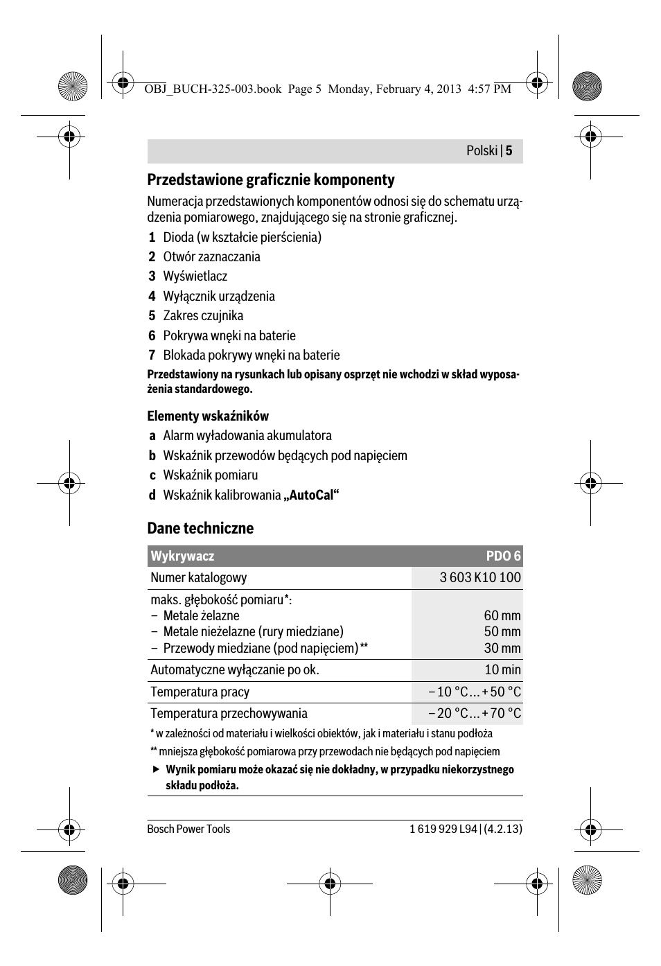
Przedstawione graficznie komponenty
Numeracja przedstawionych komponentów odnosi się do schematu urzą-
dzenia pomiarowego, znajdującego się na stronie graficznej.
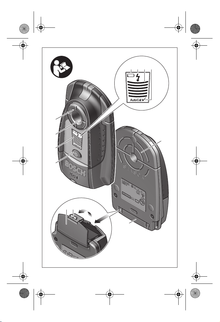
1 Dioda (w kształcie pierścienia)
2 Otwór zaznaczania
3 Wyświetlacz
4 Wyłącznik urządzenia
5 Zakres czujnika
6 Pokrywa wnęki na baterie
7 Blokada pokrywy wnęki na baterie
Przedstawiony na rysunkach lub opisany osprzęt nie wchodzi w skład wyposa-
żenia standardowego.
Elementy wskaźników
a Alarm wyładowania akumulatora
b Wskaźnik przewodów będących pod napięciem
c Wskaźnik pomiaru
d Wskaźnik kalibrowania „AutoCal“
Dane techniczne
Wykrywacz
PDO 6
Numer katalogowy
3 603 K10 100
maks. głębokość pomiaru*:
– Metale żelazne
– Metale nieżelazne (rury miedziane)
– Przewody miedziane (pod napięciem)**
60 mm
50 mm
30 mm
Automatyczne wyłączanie po ok.
10 min
Temperatura pracy
–10 °C…+50 °C
Temperatura przechowywania
–20 °C…+70 °C
* w zależności od materiału i wielkości obiektów, jak i materiału i stanu podłoża
** mniejsza głębokość pomiarowa przy przewodach nie będących pod napięciem
Wynik pomiaru może okazać się nie dokładny, w przypadku niekorzystnego
składu podłoża.
OBJ_BUCH-325-003.book Page 5 Monday, February 4, 2013 4:57 PM
6 | Polski
1 619 929 L94 | (4.2.13)
Bosch Power Tools
Montaż
Wkładanie/wymiana baterii
Zaleca się eksploatację urządzenia pomiarowego przy użyciu baterii alka-
liczno-manganowych lub akumulatorów.
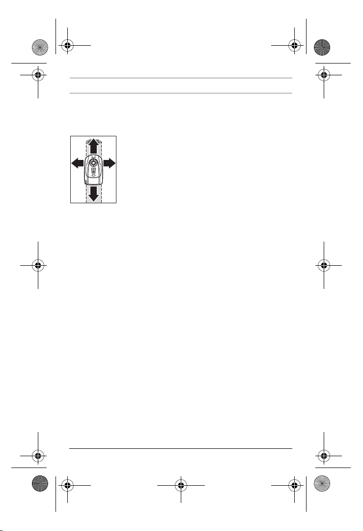
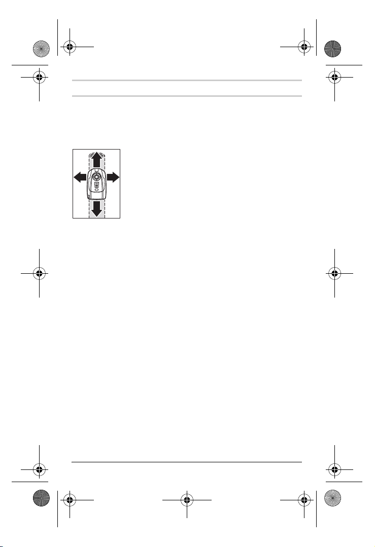
By otworzyć pokrywkę wnęki na baterie
6 należy przesunąć jej blokadę 7
w kierunku wskazanym przez strzałkę, następnie można zdjąć pokrywkę.
Do wnęki włożyć dołączone do zestawu baterie. Należy przy tym zacho-
wać prawidłową biegunowość zgodnie ze schematem umieszczonym we-
wnątrz wnęki.
Po ukazaniu się na wyświetlaczu alarmowego wskaźnika naładowania
akumulatora
a, z urządzenia można korzystać jeszcze przez ok. 1 godziny
w przypadku baterii alkaliczno-manganowych (w przypadku akumulato-
rów – przez krótszy okres czasu). Jeżeli wskaźnik wyładowania baterii
a
miga, możliwy jest jeszcze pomiar trwający ok 10 min. Jeżeli migają i
wskaźnik wyładowania baterii
a i pierścień 1 (czerwony), żaden pomiar
nie jest już możliwy i baterię lub akumulator należy wymienić.
Jeżeli urządzenie pomiarowe nie będzie przez dłuższy czas używa-
ne, należy wyjąć z niego baterię lub akumulator. Baterie i akumula-
tory nieużywane przez dłuższy okres czasu mogą ulec korozji lub samo-
rozładowaniu.
Relatywna wilgotność powietrza maks.
80 %
Bateria
Akumulator
1 x 9 V 6LR61
1 x 9 V 6F22
Czas pracy (baterii alkaliczno-manganowych) ok.
6 h
Ciężar odpowiednio do EPTA-Procedure 01/2003
0,2 kg
Wykrywacz
PDO 6
* w zależności od materiału i wielkości obiektów, jak i materiału i stanu podłoża
** mniejsza głębokość pomiarowa przy przewodach nie będących pod napięciem
Wynik pomiaru może okazać się nie dokładny, w przypadku niekorzystnego
składu podłoża.
OBJ_BUCH-325-003.book Page 6 Monday, February 4, 2013 4:57 PM
Polski |
7
Bosch Power Tools
1 619 929 L94 | (4.2.13)
Praca urządzenia
Włączenie
Urządzenie pomiarowe należy chronić przed wilgocią i bezpośred-
nim napromieniowaniem słonecznym.
Narzędzie należy chronić przed ekstremalnie wysokimi lub niskimi
temperaturami, a także przed wahaniami temperatury. Nie należy
go na przykład pozostawiać na dłuższy okres czasu w samochodzie.
W przypadku, gdy urządzenie pomiarowe poddane było większym wa-
haniom temperatury, należy przed użyciem odczekać, aż powróci ono
do normalnej temperatury. Ekstremalnie wysokie lub niskie tempera-
tury, a także silne wahania temperatury mogą mieć negatywny wpływ
na precyzję pomiaru.
Należy unikać silnych uderzeń i nie dopuszczać do upadku urzą-
dzenia pomiarowego.
Włączanie/wyłączanie
Przed włączeniem urządzenia pomiarowego należy upewnić się,
czy okolice czujnika 5 nie uległy zawilgoceniu. W przypadku stwier-
dzenia wilgoci, urządzenie pomiarowe należy wytrzeć do sucha ście-
reczką.
W celu
włączenia urządzenia pomiarowego wcisnąć włącznik/wyłącznik 4.
Po wykonaniu krótkiego autotestu urządzenie pomiarowe jest gotowe do
eksploatacji. Gotowość do pracy sygnalizowana jest pojawieniem się ha-
czyka za wskaźnikiem kalibrowania
„AutoCal“ d.
W celu
wyłączenia urządzenia pomiarowego należy nacisnąć włącznik/
wyłącznik
4.
Jeżeli przez ok. 10 min. nie zostanie wykonany żaden pomiar, urządzenie
pomiarowe wyłącza się automatycznie w celu oszczędzania baterii.
Przed przystąpieniem do wiercenia otworów w ścianach, cięcia
lub frezowania, należy się dodatkowo zabezpieczyć, sięgając do
innych źródeł informacji. Ponieważ na wyniki pomiarów wpływ mogą
mieć zarówno czynniki zewnętrzne, jak i właściwości ściany, niebez-
pieczeństwo może zaistnieć mimo iż w zakresie sensora nie został wy-
kryty żaden obiekt (pierścień
1 świeci się na zielono).
OBJ_BUCH-325-003.book Page 7 Monday, February 4, 2013 4:57 PM
8 | Polski
1 619 929 L94 | (4.2.13)
Bosch Power Tools
Rodzaje pracy
Urządzenie pomiarowe wykrywa obiekty znajdujące się w zasięgu czuło-
ści czujnika
5.
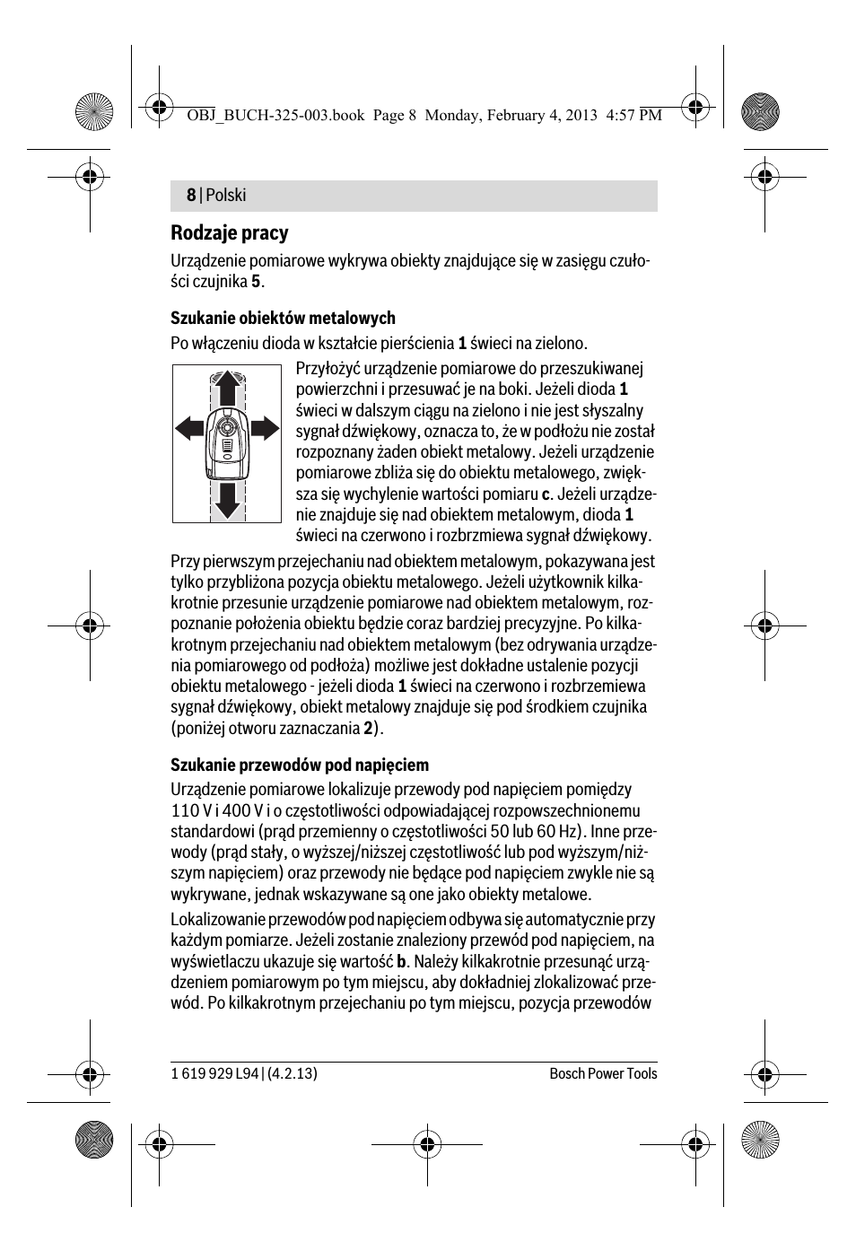
Szukanie obiektów metalowych
Po włączeniu dioda w kształcie pierścienia
1 świeci na zielono.
Przyłożyć urządzenie pomiarowe do przeszukiwanej
powierzchni i przesuwać je na boki. Jeżeli dioda
1
świeci w dalszym ciągu na zielono i nie jest słyszalny
sygnał dźwiękowy, oznacza to, że w podłożu nie został
rozpoznany żaden obiekt metalowy. Jeżeli urządzenie
pomiarowe zbliża się do obiektu metalowego, zwięk-
sza się wychylenie wartości pomiaru
c. Jeżeli urządze-
nie znajduje się nad obiektem metalowym, dioda
1
świeci na czerwono i rozbrzmiewa sygnał dźwiękowy.
Przy pierwszym przejechaniu nad obiektem metalowym, pokazywana jest
tylko przybliżona pozycja obiektu metalowego. Jeżeli użytkownik kilka-
krotnie przesunie urządzenie pomiarowe nad obiektem metalowym, roz-
poznanie położenia obiektu będzie coraz bardziej precyzyjne. Po kilka-
krotnym przejechaniu nad obiektem metalowym (bez odrywania urządze-
nia pomiarowego od podłoża) możliwe jest dokładne ustalenie pozycji
obiektu metalowego — jeżeli dioda
1 świeci na czerwono i rozbrzemiewa
sygnał dźwiękowy, obiekt metalowy znajduje się pod środkiem czujnika
(poniżej otworu zaznaczania
2).
Szukanie przewodów pod napięciem
Urządzenie pomiarowe lokalizuje przewody pod napięciem pomiędzy
110 V i 400 V i o częstotliwości odpowiadającej rozpowszechnionemu
standardowi (prąd przemienny o częstotliwości 50 lub 60 Hz). Inne prze-
wody (prąd stały, o wyższej/niższej częstotliwość lub pod wyższym/niż-
szym napięciem) oraz przewody nie będące pod napięciem zwykle nie są
wykrywane, jednak wskazywane są one jako obiekty metalowe.
Lokalizowanie przewodów pod napięciem odbywa się automatycznie przy
każdym pomiarze. Jeżeli zostanie znaleziony przewód pod napięciem, na
wyświetlaczu ukazuje się wartość
b. Należy kilkakrotnie przesunąć urzą-
dzeniem pomiarowym po tym miejscu, aby dokładniej zlokalizować prze-
wód. Po kilkakrotnym przejechaniu po tym miejscu, pozycja przewodów
OBJ_BUCH-325-003.book Page 8 Monday, February 4, 2013 4:57 PM
Polski |
9
Bosch Power Tools
1 619 929 L94 | (4.2.13)
pod napięciem może zostać wskazana bardzo dokładnie. Jeżeli urządze-
nie pomiarowe znajduje się bardzo blisko przewodu, dioda
1 miga na
czerwono i rozbrzmiewa szybki, przerywany sygnał dźwiękowy.
Znalezienie przewodów pod napięciem ułatwia podłączenie odbiorników
prądu elektrycznego (np. lamp, narzędzi) do szukanego przewodu i włą-
czenie ich. Wydajność szukania przewodów 110 V, 230 V i 400 V (prąd
trójfazowy) jest mniej więcej równa.
W niektórych przypadkach (jak np. za powierzchniami metalowymi lub za
powierzchniami o dużej wilgotności) nie jest zagwarantowane precyzyjne
zlokalizowanie przewodów pod napięciem. Jeżeli na dużej powierzchni
ukazywana jest wartość pomiaru
c, oznacza to, że materiał ekranuje elek-
trycznie i niezawodne zlokalizowanie przewodów pod napięciem nie jest
możliwe.
Wskazówki dotyczące pracy
Na dokładność wyników pomiarowych mogą zasadniczo wpłynąć
określone warunki otoczenia. Zaliczają się do nich np. bliskość
przyrządów, które wytwarzają silne pola magnetyczne lub elektro-
magnetyczne, wilgoć, materiały budowlane zawierające metal,
materiały izolacyjne laminowane folią aluminiową, jak również ta-
pety przewodzące prąd lub płytki ceramiczne. Przed przystąpie-
niem do wiercenia, frezowania lub dokonywania cięć w ścianach, sufi-
tach, podłogach należy dlatego skonsultować również inne źródła in-
formacji (np. plany budowlane).
Zaznaczanie obiektów
W razie potrzeby można zaznaczyć znalezione obiekty. Przy maksymal-
nym wychyleniu wartości pomiaru
c, środek obiektu znajduje się pod ot-
worem zaznaczania
2. Granice obiektu można ustalić, obserwując zmianę
koloru diody
1 z zielonego na czerwony. Zaznaczyć to miejsce przez otwór
zaznaczania używając ołówka
2.
Wskaźnik „AutoCal“
W przypadku, gdy haczyk za wskaźnikiem kalibrowania
„AutoCal“ d miga
przez dłuższy czas, lub nie jest więcej ukazany, niemożliwy jest dalej po-
miar niezawodny. W tym przypadku należy urządzenie pomiarowe prze-
słać do autoryzowanego punktu serwisowego firmy Bosch.
OBJ_BUCH-325-003.book Page 9 Monday, February 4, 2013 4:57 PM
10 | Polski
1 619 929 L94 | (4.2.13)
Bosch Power Tools
Konserwacja i serwis
Konserwacja i czyszczenie
Jeżeli wartość pomiaru
c zmienia się ciągle, choć w pobliżu urządzenia nie
ma obiektu metalowego, można przeprowadzić ręczne kalibrowanie urzą-
dzenia pomiarowego. W tym celu usunąć wszystkie metalowe obiekty w
pobliżu urządzenia pomiarowego (również zegarek lub metalowe pier-
ścionki/ obrączki) i podnieść urządzenie w powietrzu do góry. Wcisnąć w
wyłączonym urządzeniu pomiarowym włącznik/wyłącznik
4 tak długo, aż
dioda
1 zaświeci jednocześnie na zielono i na czerwono. Puścić w tym mo-
mencie przycisk. Jeżeli kalibrowanie zakończyło się powodzeniem, urzą-
dzenie pomiarowe wystartuje po kilku sekundach ponownie i będzie goto-
we do eksploatacji.
Zanieczyszczenia należy wycierać suchą, miękką ściereczką. Nie należy
używać żadnych środków czyszczących lub rozpuszczalników.
Aby nie zakłócać funkcji pomiaru, nie wolno umieszczać w polu działania
czujnika
5 na przedniej i tylnej stronie urządzenia, żadnych naklejek ani
tabliczek, a w szczególności tabliczek metalowych.
Jeśli urządzenie pomiarowe, mimo starannych metod produkcji i kontroli
uległoby awarii, naprawę powinien przeprowadzić autoryzowany serwis
elektronarzędzi firmy Bosch. Nie wolno samemu otwierać urządzenia po-
miarowego.
Przy wszystkich zapytaniach i zamówieniach części zamiennych, proszę
podać koniecznie 10 cyfrowy numer katalogowy podany na tabliczce
znamionowej urządzenia pomiarowego.
Obsługa klienta oraz doradztwo dotyczące użytkowania
W punkcie obsługi klienta można uzyskać odpowiedzi na pytania dotyczą-
ce napraw i konserwacji nabytego produktu, a także dotyczące części za-
miennych. Rysunki rozłożeniowe oraz informacje dotyczące części za-
miennych można znaleźć również pod adresem:
www.bosch-pt.com
Nasz zespół doradztwa dotyczącego użytkowania odpowie na wszystkie
pytania związane z produktami firmy Bosch oraz ich osprzętem.
OBJ_BUCH-325-003.book Page 10 Monday, February 4, 2013 4:57 PM
15:17
How to Use a Pipe & Cable Detector — DIY Tips!
10:49
Детектор проводки и металлов BOSCH PDO 6 в работе
02:50
Презентация детектора Bosch PDO 6
01:10
Bosch PDO-6. Детектор скрытой проводки
11:08
Детекторы BOSCH PDO 6 vs SKIL 0551 AB (СРАВНИТЕЛЬНЫЙ ТЕСТ)
03:47
detector metal bosch pdo multi — demo beton
02:30
Bosh PDO 6 Digital Measuring Detector Demonstration
01:51
Bosch Leitungssucher
Нажмите на кнопку для помощи
Robert Bosch GmbH
Power Tools Division
70745 Leinfelden-Echterdingen
Germany
www.bosch-pt.com
1 609 929 X43 (2010.11) T / 164 WEU
WEU WEU
PDO 6PDO 6PDO 6
de Originalbetriebsanleitung
en Original instructions
fr Notice originale
es Manual original
pt Manual original
it Istruzioni originali
nl Oorspronkelijke
gebruiksaanwijzing
da Original brugsanvisning
sv Bruksanvisning i original
no Original driftsinstruks
fi Alkuperäiset ohjeet
el
Πρωτότυπο οδηγιών χρήσης
tr Orijinal işletme talimat
ar
ΕΎϤϴϠόΗϞϴϐθΘϟΔϴϠλϷ
OBJ_BUCH-308-002.book Page 1 Wednesday, November 3, 2010 9:43 AM
Цифровой детектор Bosch PDO 6 используется для обнаружения черных и цветных металлов, арматурной стали, электрокабелей под напряжением в стенах, потолках и полах.
Это прочный, компактный и надежный прибор, который пригодится как в быту, так и на производстве. Максимальная глубина обнаружения черных металлов составляет 60 миллиметров, цветных металлов – 50 мм, а медных кабелей под напряжением – 30 мм.
Корпус прибора выполнен из прочной и приятной на ощупь пластмассы, а также оснащен мягкой накладкой для надежного и удобного захвата. Детектор Bosch PDO 6 очень прост в эксплуатации, и не требует для работы специальных навыков и умений. Все управление процессом поиска осуществляется при помощи одной кнопки.
При включении питания детектор скрытой проводки и металла производит автоматическую калибровку, после чего он сразу готов к работе. Цифровой жидкокристаллический дисплей обеспечивает легкое считывание результатов измерений. Детектор Bosch PDO 6 оснащен светящимся маркировочным кольцом, которое обеспечивает однозначное разрешение сверление при зеленой индикации, и запрещение при красной.
Питание прибора осуществляется от щелочной батареи или от аккумулятора, обеспечивающих около 6 часов непрерывной работы. Функция автоматического выключения после 10 минут простоя позволит экономить энергию.
Bosch Detector PDO 6
Robert Bosch GmbH
Power Tools Division
70745 Leinfelden-Echterdingen
Germany
www.bosch-pt.com
1 609 929 X43 (2010.11) T / 164 WEU
WEU WEU
PDO 6
PDO 6
PDO 6
PDO 6
PDO 6
de Originalbetriebsanleitung
en Original instructions
fr Notice originale
es Manual original
pt Manual original
it Istruzioni originali
nl Oorspronkelijke
gebruiksaanwijzing
da Original brugsanvisning
sv Bruksanvisning i original
no Original driftsinstruks
fi Alkuperäiset ohjeet
el
Πρωτότυπο οδηγιών χρήσης
tr Orijinal işletme talimat
ar
ΕΎϤϴϠόΗϞϴϐθΘϟΔϴϠλϷ
OBJ_BUCH-308-002.book Page 1 Wednesday, November 3, 2010 9:43 AM
User manual
View the manual for the Bosch Detector PDO 6 here, for free. This manual comes under the category detectors and has been rated by 3 people with an average of a 7.6. This manual is available in the following languages: English. Do you have a question about the Bosch Detector PDO 6 or do you need help?
Ask your question here
Product Images (3)

Bosch Detector PDO 6 specifications
Below you will find the product specifications and the manual specifications of the Bosch Detector PDO 6.
The Bosch detector PDO 6 is a lightweight and compact device weighing 200 grams. It is designed to detect objects with a sensor distance of 0.6 meters.
This detector operates with a power requirement of 9 volts, ensuring reliable performance. It is compatible with various power sources, allowing for flexibility in its use.
The Bosch detector PDO 6 is equipped with advanced sensor technology, providing accurate and precise detection capabilities. It is capable of detecting a wide range of materials, including metal objects such as nails and pipes.
With its compact design, this device is portable and easy to handle. It can be easily carried and used in various settings, making it suitable for both professional and DIY applications.
The Bosch detector PDO 6 is constructed with high-quality materials, ensuring durability and longevity. It is designed to withstand the rigors of frequent use and can withstand heavy-duty tasks.
The detector is user-friendly and features intuitive controls, making it easy to operate. It provides clear and reliable feedback, enabling users to quickly and accurately locate objects.
Overall, the Bosch detector PDO 6 is a versatile and reliable device, ideal for anyone in need of accurate and efficient object detection.
General
| Brand | Bosch |
| Model | Detector PDO 6 | 0 603 010 100 |
| Product | detector |
| EAN | 3165140435543, 5052276391738, 3147280088544, 0791429335803, 4054317000815, 5053106675424, 5020010199711, 5053086214675 |
| Language | English |
| Filetype | Manual (PDF) |
Weight & dimensions
Features
Power
show more
Frequently Asked Questions
Can’t find the answer to your question in the manual? You may find the answer to your question in the FAQs about the Bosch Detector PDO 6 below.
How do I properly calibrate the Bosch Detector PDO 6?
A proper calibration involves switching on the device in the desired mode and waiting for a short self-calibration process to be completed. This ensures accurate results during your detection tasks.
What is the maximum depth that the Bosch Detector PDO 6 can detect?
The Bosch Detector PDO 6 is capable of detecting live electrical wires up to a maximum depth of 60 millimetres.
How can I change the measurement units on the Bosch Detector PDO 6?
To alter the measurement units, just press and hold down the unit change button until the desired units (like metres or feet) are shown on the screen.
What is the optimal operating temperature range for the Bosch Detector PDO 6?
The Bosch Detector PDO 6 is designed to operate under temperatures ranging from 0°C to 40°C (32°F to 104°F) to ensure accurate and reliable performance.
How can I ensure the battery life of the Bosch Detector PDO 6 lasts as long as possible?
To maximize the battery life, it is recommended to switch off the device when not in use and replace the batteries when the low battery indicator appears on the screen. Additionally, avoid exposing the detector to extreme temperatures, as this may negatively impact battery performance.
Does the Bosch Detector PDO 6 have a long sensor distance?
No, the Bosch Detector PDO 6 has a sensor distance of 0.6 m, which is relatively short compared to some other detectors on the market. This means that it may not be able to detect objects at longer distances.
What power requirements does the Bosch Detector PDO 6 have?
The Bosch Detector PDO 6 requires 9V of power. This is a standard power requirement and should be easily met by most users.
What is the weight of the Bosch Detector PDO 6?
The Bosch Detector PDO 6 has a weight of 200 g.
Is the manual of the Bosch Detector PDO 6 available in English?
Yes, the manual of the Bosch Detector PDO 6 is available in English .
Is your question not listed? Ask your question here
OBJ_BUCH-308-001.book Page 1 Wednesday, January 17, 2007 9:55 AM
Bedienungsanleitung
Operating
instructions
Instructions
d’emploi
Instrucciones de
servicio
Manual de
instruções
Istruzioni d’uso
Gebruiksaanwijzing
Betjenings-
vejledning
Bruksanvisning
Brukerveiledningen
Käyttöohje
Οδηγία χειρισµού
Kullanım kılavuzu
Deutsch
English
Français
Español
Português
Italiano
Nederlands
Dansk
Svenska
Norsk
Suomi
Ελληνικά
Türkçe
PDO 6

OBJ_BUCH-308-001.book Page 2 Wednesday, January 17, 2007 9:55 AM
Deutsch . . . . . . . . . . . . . . . . . . . . . . . Seite 4
English . . . . . . . . . . . . . . . . . . . . . . . . Page 12
Français . . . . . . . . . . . . . . . . . . . . . . . Page 20
Español . . . . . . . . . . . . . . . . . . . . . Página 27
Português . . . . . . . . . . . . . . . . . . . Página 35
Italiano . . . . . . . . . . . . . . . . . . . . . . Pagina 42
Nederlands . . . . . . . . . . . . . . . . . . Pagina 50
Dansk. . . . . . . . . . . . . . . . . . . . . . . . . Side 57
Svenska . . . . . . . . . . . . . . . . . . . . . . . Sida 63
Norsk . . . . . . . . . . . . . . . . . . . . . . . . . Side 69
Suomi. . . . . . . . . . . . . . . . . . . . . . . . . . Sivu 75
Ελληνικά . . . . . . . . . . . . . . . . . . . Σελίδα 81
Türkçe . . . . . . . . . . . . . . . . . . . . . . . Sayfa 89
2 1 609 929 K82 • 17.1.07
M
ade
i
n
Cz
ec
h Re
publ
ic
Ro
b
ert B
o
s
ch G
m
b
H
D
—
7
074
5
Lei
nf
el
d
en
—
E
c
h
ter
d
i
ng
en
>
AB8
<
>
AB8
<
>
AB8AB8
<
>
AB8
<
epublic
d
ing
en
Republic
OBJ_BUCH-308-001.book Page 3 Wednesday, January 17, 2007 9:55 AM
abcdabcd
1
2
5
3
4
76
SENSOR
SENSOR
SENSOR
Bat
Bat
ter
ter
y 9V 6LR61
y 9V 6LR61
Robert Bosch GmbH
Robert Bosch GmbH
D — 70745 Leinfelden — Echterdingen
D — 70745 Leinfelden — Echt
Made in Czech Republic
Made in Cze
ch Republic
erdingen
>
>
AB8
AB8
<
<
6
31 609 929 K82 • 17.1.07
OBJ_BUCH-308-001.book Page 4 Wednesday, January 17, 2007 9:55 AM
Funktionsbeschreibung
Optimales Arbeiten mit dem Messwerkzeug ist
nur möglich, wenn Sie die Bedienungsanleitung
und die Arbeitshinweise vollständig lesen und
die darin enthaltenen Anweisungen strikt befolgen. BEWAHREN SIE DIESE ANWEISUNGEN
GUT AUF.
Bestimmungsgemäßer Gebrauch
Das Messwerkzeug ist bestimmt zur Suche nach Metallen (Eisenund Nichteisenmetalle, z.B. Armierungseisen) sowie spannungsführenden Leitungen in Wänden, Decken und Fußböden.
Abgebildete Komponenten
Die Nummerierung der abgebildeten Komponenten bezieht sich auf
die Darstellung des Messwerkzeugs auf der Grafikseite.
1 Leuchtring
2 Markierungsöffnung
3 Display
4 Ein-Aus-Taste
5 Sensorbereich
6 Batteriefachdeckel
7 Arretierung des Batteriefachdeckels
Anzeigenelemente
a Batterie-Anzeige
b Anzeige von spannungsführenden Leitungen
c Messanzeige
d Kalibrierungsanzeige „AutoCal“
4 | Deutsch 1 609 929 K82 • 17.1.07
OBJ_BUCH-308-001.book Page 5 Wednesday, January 17, 2007 9:55 AM
Technische Daten
Digitales Ortungsgerät PDO 6
Sachnummer 3 603 K10 100
max. Erfassungstiefe*:
– Eisenmetalle
– Nichteisenmetalle (Kupferrohr)
– Kupferleitungen (spannungsführend)**
Abschaltautomatik nach ca. 10 min
Betriebstemperatur –10 °C… +50 °C
Lagertemperatur –20°C…+70°C
Batterie
Akku
Betriebsdauer (Alkali-Mangan-Batterie) ca. 6h
Gewicht entsprechend
EPTA-Procedure 01/2003 0,2 kg
* abhängig von Material und Größe der Objekte sowie Material und Zustand
des Untergrundes
** geringere Erfassungstiefe bei nicht spannungsführenden Leitungen
Bitte beachten Sie die Sachnummer auf dem Typenschild Ihres Mess-
werkzeugs, die Handelsbezeichnungen einzelner Messwerkzeuge können
variieren.
60 mm
50 mm
30 mm
1x9V6LR61
1x9V6F22
Montage
Batterien einsetzen/wechseln
Verwenden Sie ausschließlich Alkali-Mangan-Batterien oder Akkus.
Zum Öffnen des Batteriefachdeckels 6 drücken Sie die Arretierung
7 in Pfeilrichtung und klappen den Batteriefachdeckel nach unten.
Setzen Sie die mitgelieferte Batterie ein. Achten Sie dabei auf die
richtige Polung.
Deutsch | 51 609 929 K82 • 17.1.07
OBJ_BUCH-308-001.book Page 6 Wednesday, January 17, 2007 9:55 AM
Leuchtet die Batterie-Anzeige a im Display auf, dann können Sie bei
Verwendung von Alkali-Mangan-Batterien noch ca. 1 Stunde messen (bei Akkus kürzere Standzeit). Blinkt die Anzeige a, dann sind
noch ca. 10 min Messung möglich. Blinken die Batterie-Anzeige a
und der Leuchtring 1 (rot), dann ist keine Messung mehr möglich
und Sie müssen die Batterie bzw. den Akku wechseln.
f Nehmen Sie die Batterie aus dem Messwerkzeug, wenn
Sie es längere Zeit nicht benutzen. Die Batterie kann bei län-
gerer Lagerung korrodieren oder sich selbst entladen.
Betrieb
Inbetriebnahme
f Schützen Sie das Messwerkzeug vor Nässe und direkter
Sonneneinstrahlung.
Ein-/Ausschalten
f Stellen Sie vor dem Einschalten des Messwerkzeugs
sicher, dass der Sensorbereich 5 nicht feucht ist. Reiben
Sie das Messwerkzeug gegebenenfalls mit einem Tuch trocken.
f War das Messwerkzeug einem starken Temperaturwech-
sel ausgesetzt, dann lassen Sie es vor dem Einschalten
austemperieren.
Drücken Sie zum Einschalten des Messwerkzeugs die Ein-AusTaste 4.
Nach einem kurzen Selbsttest ist das Messwerkzeug betriebsbereit.
Die Betriebsbereitschaft wird durch einen Haken hinter der Kalibrierungsanzeige „AutoCal“ d angezeigt.
Zum Ausschalten des Messwerkzeugs drücken Sie die Ein-AusTaste 4.
Erfolgt ca. 10 min lang keine Messung, dann schaltet sich das
Messwerkzeug zur Schonung der Batterien automatisch ab.
6 | Deutsch 1 609 929 K82 • 17.1.07

OBJ_BUCH-308-001.book Page 7 Wednesday, January 17, 2007 9:55 AM
Betriebsarten
Das Messwerkzeug detektiert Objekte unterhalb des Sensorbereiches 5.
Metallobjekte suchen
Nach dem Einschalten leuchtet der Ring 1 grün.
Setzen Sie das Messwerkzeug auf die zu untersuchende Oberfläche und bewegen Sie es seitlich.
Leuchtet der Ring 1 weiterhin grün und ertönt kein
Signalton, ist im Untergrund kein Metallobjekt
erkennbar. Nähert sich das Messwerkzeug einem
Metallobjekt, nimmt der Ausschlag in der Messanzeige c zu. Über einem Metallobjekt wird der Ring 1
rot und es ertönt ein Signalton.
Beim ersten Überfahren wird die Position des Metallobjekts nur
grob angezeigt. Wenn Sie das Metallobjekt mehrmals mit dem
Messwerkzeug überfahren, wird die Objekterkennung immer präziser. Nach mehrmaligem Überfahren (ohne das Messwerkzeug vom
Untergrund abzuheben) kann die Position des Metallobjektes genau
angezeigt werden: Leuchtet der Ring 1 rot und ertönt der Signalton,
liegt das Metallobjekt unterhalb der Sensormitte (unterhalb der Markierungsöffnung 2).
Spannungsführende Leitungen suchen
Das Messwerkzeug zeigt Leitungen an, die Spannung zwischen
110 V und 400 V führen und deren Frequenz dem weit verbreiteten
Standard (Wechselstrom mit 50 bzw. 60 Hz) entspricht. Andere Leitungen (Gleichstrom, höhere/niedrigere Frequenz oder Spannung)
sowie nicht spannungsführende Leitungen können nicht zuverlässig
gefunden werden, sie werden aber gegebenenfalls als Metallobjekte angezeigt.
Die Suche nach spannungsführenden Leitungen erfolgt automatisch
bei jeder Messung. Wird eine spannungsführende Leitung gefunden,
erscheint im Display die Anzeige b. Bewegen Sie das Messwerkzeug
wiederholt über die Fläche, um die spannungsführende Leitung
genauer zu lokalisieren. Nach mehrmaligem Überfahren kann die
Position der spannungsführenden Leitung sehr genau angezeigt werden. Ist das Messwerkzeug sehr nahe an der Leitung, dann blinkt der
Leuchtring 1 rot und der Signalton ertönt mit schneller Tonfolge.
Deutsch | 71 609 929 K82 • 17.1.07
OBJ_BUCH-308-001.book Page 8 Wednesday, January 17, 2007 9:55 AM
Spannungsführende Leitungen können leichter gefunden werden,
wenn Stromverbraucher (z.B. Leuchten, Geräte) an der gesuchten
Leitung angeschlossen und eingeschaltet werden. Leitungen mit
110 V, 230 V und 400 V (Drehstrom) werden mit ungefähr derselben Suchleistung gefunden.
Unter bestimmten Bedingungen (wie z.B. hinter Metalloberflächen
oder hinter Oberflächen mit hohem Wassergehalt) können spannungsführende Leitungen nicht sicher gefunden werden. Wird über
einem größeren Bereich überall ein Messwert c angezeigt, dann
schirmt das Material elektrisch ab und die Suche nach spannungsführenden Leitungen ist nicht zuverlässig.
Arbeitshinweise
f Die Messergebnisse können prinzipbedingt durch be-
stimmte Umgebungsbedingungen beeinträchtigt werden.
Dazu gehören z.B. die Nähe von Geräten, die starke magnetische oder elektromagnetische Felder erzeugen, Nässe, metallhaltige Baumaterialien, alukaschierte Dämmstoffe oder leitfähige Tapeten. Beachten Sie deshalb vor dem
Bohren, Sägen oder Fräsen in Wände, Decken oder Böden auch
andere Informationsquellen (z.B. Baupläne).
Objekte markieren
Sie können gefundene Objekte bei Bedarf markieren. Bei maximalem
Ausschlag der Messanzeige c befindet sich die Mitte des Objektes
unter der Markierungsöffnung 2. Die Grenzen eines Objektes können
Sie durch den Wechsel des Leuchtringes 1 von grün zu rot finden.
Markieren Sie die gesuchte Stelle mit einem Stift durch die Markierungsöffnung 2.
Anzeige „AutoCal“
Blinkt der Haken hinter der Kalibrierungsanzeige „AutoCal“ d über
längere Zeit oder wird er nicht mehr angezeigt, kann nicht mehr
zuverlässig gemessen werden. Senden Sie das Messwerkzeug in
diesem Fall an eine autorisierte Bosch-Kundendienststelle.
8 | Deutsch 1 609 929 K82 • 17.1.07

OBJ_BUCH-308-001.book Page 9 Wednesday, January 17, 2007 9:55 AM
Wartung und Service
Wartung und Reinigung
Schlägt die Messanzeige c dauerhaft aus, obwohl sich kein Objekt
aus Metall in der Nähe des Messwerkzeugs befindet, kann das
Messwerkzeug manuell kalibriert werden. Entfernen Sie dazu alle
Objekte aus der Nähe des Messwerkzeugs (auch Armbanduhr oder
Ring aus Metall) und halten Sie das Messwerkzeug in die Luft. Drücken Sie bei ausgeschaltetem Messwerkzeug die Ein-Aus-Taste 4
so lange, bis der Leuchtring 1 gleichzeitig rot und grün leuchtet. Lassen Sie dann die Taste los. Verlief die Kalibrierung erfolgreich, dann
startet das Messwerkzeug nach einigen Sekunden neu und ist wieder betriebsbereit.
Wischen Sie Verschmutzungen mit einem trockenen, weichen Tuch
ab. Verwenden Sie keine Reinigungs- oder Lösemittel.
Um die Messfunktion nicht zu beeinflussen, dürfen im Sensorbereich 5 auf der Vorder- und Rückseite des Messwerkzeugs keine
Aufkleber oder Schilder, insbesondere keine Schilder aus Metall,
angebracht werden.
Sollte das Messwerkzeug trotz sorgfältiger Herstellungs- und Prüfverfahren einmal ausfallen, ist die Reparatur von einer autorisierten
Kundendienststelle für Bosch-Elektrowerkzeuge ausführen zu lassen.
Geben Sie bei allen Rückfragen und Ersatzteilbestellungen bitte
unbedingt die 10-stellige Sachnummer laut Typenschild des Messwerkzeugs an.
Deutsch | 91 609 929 K82 • 17.1.07
OBJ_BUCH-308-001.book Page 10 Wednesday, January 17, 2007 9:55 AM
Service und Kundenberater
Explosionszeichnungen und Informationen zu Ersatzteilen finden Sie
unter:
www.bosch-pt.com
www.powertool-portal.de, das Internetportal für Heimwerker und
Gartenfreunde.
www.dha.de, das komplette Service-Angebot der Deutschen
Heimwerker Akademie.
Deutschland
Robert Bosch GmbH
Servicezentrum Elektrowerkzeuge
Zur Luhne 2
37589 Kalefeld
✆ . . . . . . . . . . . . . . . . . . . . . . . . . . . . . . . . . . . . . . 0 18 05/70 74 10
Fax . . . . . . . . . . . . . . . . . . . . . . . . . . . . . . . . . . . . . 0 18 05/70 74 11
Österreich
ABE Service GmbH
Jochen-Rindt-Straße 1
1232 Wien
✆ Service . . . . . . . . . . . . . . . . . . . . . . . . . . . . . . +43 (0)1/ 61 03 80
Fax . . . . . . . . . . . . . . . . . . . . . . . . . . . . . . . . . .+43 (0)1/61 03 84 91
✆ Kundenberater . . . . . . . . . . . . . . . . . . . .+43 (0)1/7 97 22 30 66
E-Mail: abe@abe-service.co.at
Schweiz
✆ . . . . . . . . . . . . . . . . . . . . . . . . . . . . . . . . . . . . . . . 0 44/8 47 15 11
Fax . . . . . . . . . . . . . . . . . . . . . . . . . . . . . . . . . . . . . . 0 44/8 47 15 51
Luxemburg
✆ . . . . . . . . . . . . . . . . . . . . . . . . . . . . . . . . . . . . +32 (0)70/22 55 65
Fax . . . . . . . . . . . . . . . . . . . . . . . . . . . . . . . . . . . +32 (0)70/22 55 75
E-Mail: outillage.gereedschap@be.bosch.com
10 | Deutsch 1 609 929 K82 • 17.1.07
OBJ_BUCH-308-001.book Page 11 Wednesday, January 17, 2007 9:55 AM
Entsorgung
Messwerkzeuge, Zubehör und Verpackungen sollen einer umweltgerechten Wiederverwertung zugeführt werden.
Nur für EU-Länder:
Werfen Sie Messwerkzeuge nicht in den Hausmüll!
Gemäß der Europäischen Richtlinie 2002/96/EG
über Elektro- und Elektronik-Altgeräte und ihrer
Umsetzung in nationales Recht müssen nicht mehr
gebrauchsfähige Messwerkzeuge getrennt gesammelt und einer umweltgerechten Wiederverwertung
zugeführt werden.
Akkus/Batterien:
Werfen Sie Akkus/Batterien nicht in den Hausmüll, ins Feuer oder
ins Wasser. Akkus/Batterien sollen gesammelt, recycelt oder auf
umweltfreundliche Weise entsorgt werden.
Nur für EU-Länder:
Gemäß der Richtlinie 91/157/EWG müssen defekte oder verbrauchte Akkus/Batterien recycelt werden.
Nicht mehr gebrauchsfähige Akkus/Batterien können direkt abgegeben werden bei:
Deutschland
Recyclingzentrum Elektrowerkzeuge
Osteroder Landstraße 3
37589 Kalefeld
Schweiz
Batrec AG
3752 Wimmis BE
Änderungen vorbehalten.
Deutsch | 111 609 929 K82 • 17.1.07

OBJ_BUCH-308-001.book Page 12 Wednesday, January 17, 2007 9:55 AM
Functional Description
Optimal working with the measuring tool is possible only when the operating instructions and
information are read completely, and the
instructions contained therein are strictly followed. SAVE THESE INSTRUCTIONS.
Intended Use
The measuring tool is intended for the detection of metals (ferrous
and non-ferrous metals, e.g., rebar) and “live” wires/conductors in
walls, ceilings and floors.
Product Features
The numbering of the product features shown refers to the illustration of the measuring tool on the graphic page.
1 Illuminated ring
2 Marking hole
3 Display
4 On/Off button
5 Sensor area
6 Battery lid
7 Latch of battery lid
Display Elements
a Battery indication
b “Live” wire indicator
c Measuring indicator
d“AutoCal” calibration indicator
12 | English 1 609 929 K82 • 17.1.07

OBJ_BUCH-308-001.book Page 13 Wednesday, January 17, 2007 9:55 AM
Technical Data
Digital Detector PDO 6
Article number 3 603 K10 100
Maximum scanning depth*:
–Ferrous metals
– Non-ferrous metals (copper pipe)
– Copper conductors (live)**
Automatic switch-off after approx. 10 min
Operating temperature –10 °C… +50 °C
Storage temperature –20°C…+70°C
Battery
Rechargeable battery
Operating lifetime
(alkali-manganese batteries) approx.
Weight according to
EPTA-Procedure 01/2003 0.2 kg
* depends on material and size of objects as well as material and condition
of structure
** less scanning depth for wires/conductors that are not “live”
Please observe the article number on the type plate of your measuring tool.
The trade names of the individual measuring tools may vary.
60 mm
50 mm
30 mm
1x9V6LR61
1x9V6F22
6h
Assembly
Inserting/Replacing the Battery
Use only alkali-manganese or rechargeable batteries.
To open the battery lid 6, press the latch 7 in the direction of the
arrow and fold the battery lid downward. Insert the battery provided.
Pay attention that the polarity is correct.
English | 131 609 929 K82 • 17.1.07
OBJ_BUCH-308-001.book Page 14 Wednesday, January 17, 2007 9:55 AM
When the battery indication a in the display lights up, measuring is
possible for approx. 1 h when using alkali-manganese batteries (service life is shorter with rechargeable batteries). When the battery indication a flashes, measuring is still possible for approx. 10 minutes.
When the battery indication a and the illuminated ring 1 (red) are
flashing, measuring is no longer possible and the battery or the
rechargeable battery respectively, must be replaced.
f If the measuring tool is not used for a long period of time,
the battery must be removed. The battery can corrode or dis-
charge itself over long periods.
Operation
Initial Operation
f Protect the measuring tool against moisture and direct
sun irradiation.
Switching On and Off
f Before switching the measuring tool on, make sure that
the sensor area 5 is not moist. If required, wipe the measur-
ing tool dry using a cloth.
f If the measuring tool was subject to an extreme temper-
ature change, allow it to adjust to the ambient temperature before switching on.
To switch on the measuring tool, press the On/Off switch 4.
After a brief self-check, the measuring tool is ready for operation.
The operational readiness is indicated by a check mark behind the
“AutoCal” calibration indicator d.
To switch the measuring tool off, press the “on/off” button 4.
When no measurements are carried out for approx. 10 minutes, the
measuring tool switches off automatically in order to extend the service life of the batteries.
14 | English 1 609 929 K82 • 17.1.07
OBJ_BUCH-308-001.book Page 15 Wednesday, January 17, 2007 9:55 AM
Operating Modes
The measuring tool detects objects below the sensor area 5.
Detecting Metal Objects
After switching on, the illuminated ring 1 lights up green.
Place the measuring tool on the surface to be
scanned and move it sidewards. When the illuminated ring 1 continues to light up green and no signal tone sounds, then no metal object is detectable
in the structual material below. When the measuring
tool comes close to a metal object, the amplitude in
the measuring indicator c increases. When the
measuring tool is above a metal object, the ring 1
turns red and a signal tone sounds.
When moving over a surface the first time, the position of the metal
object is indicated only approximately. When moving the measuring
tool over the metal object several times, the object is detected more
and more precisely. After moving over the surface above the metal
object several times (without lifting off the measuring tool from the
surface), the position of the metal object can be indicated accurately: When the illuminated ring 1 lights up red and the signal tone
sounds, then the metal object is below the centre of the sensor
(below the marking hole 2).
Scanning for “Live” Wires
The measuring tool indicates “live” wires/conductors that carry voltages between 110 V and 400 V, and a frequency corresponding
with the common standard (AC with 50 to 60 Hz). Other wires/conductors (carrying DC, higher/lower frequency or voltage) as well as
“dead” wires/conductors cannot be found reliably, but are possibly
indicated as metal objects.
The scan for “live” wires/conductors takes place automatically for
each measurement. When a “live” wire/connductor is detected, the
indicator b appears in the display. Move the measuring tool over the
surface repeatedly in order to localise the “live” wire. After moving the
measuring tool over the surface several times, the position of the
“live” wire/conductor can be indicated quite precisely. If the measuring tool is very close to the wire/conductor, then the illuminated ring
1 lights up red and the signal tone sounds with rapid tone sequence.
English | 151 609 929 K82 • 17.1.07
OBJ_BUCH-308-001.book Page 16 Wednesday, January 17, 2007 9:55 AM
“Live” wires/conductors can be detected easier when power consumers (e.g., lamps, appliances) are connected to the wire/conductor being sought and switched on. Wires/conductors with 110 V,
230 V and 400 V (three-phase current) are detected with about the
same scan capacity.
Under certain conditions (such as when behind metal surfaces or
behind surfaces with high water content), “live” wires/conductors
cannot be detected with certainty. When measuring indicator c is
indicated over a larger range, then the material is screening-off electrically and the scan for “live” wires/conductors is not reliable.
Operating Instructions
f On condition of the principle, the measuring values can
be impaired through certain ambient conditions. These
include, e.g., the proximity of other equipment that produce strong magnetic or electromagnetic fields, moisture,
metallic building materials, foil-laminated insulation
materials or conductive wallpaper. Therefore, please also
observe other information sources (e.g. construction plans)
before drilling, sawing or routing into walls, ceilings or floors.
Marking Objects
Detected objects can be marked as required. Where the amplitude of
measuring indication c is at its maximum, the centre of the object is
located below marking hole 2. The limits of an object are indicated by
the colour change of the illuminated ring 1 from green to red. Using a
pen, mark the sought after location through the marking hole 2.
“AutoCal” Calibration Indicator
When the check mark behind the “AutoCal” calibration indicator d
flashes for longer periods or if it is not displayed anymore, reliable
scanning is no longer possible. In this case, send in the measuring
tool to an authorised Bosch after-sales service agent.
16 | English 1 609 929 K82 • 17.1.07

OBJ_BUCH-308-001.book Page 17 Wednesday, January 17, 2007 9:55 AM
Maintenance and Service
Maintenance and Cleaning
When the measuring indicator c continuously shows an amplitude
even though there is no metal object in the vicinity of the measuring
tool, the measuring tool can be calibrated manually. For this, remove
all objects in the vicinity of the measuring tool (including wrist
watches or rings of metal) and hold the measuring tool up in the air.
With the measuring tool switched off, press the On/Off button 4
until the illuminated ring 1 lights up red and green at the same time.
Then release the button. When the calibration process was successful, the measuring tool will start over after a few seconds and is
then ready for operation.
Wipe away debris or contamination with a dry, soft cloth. Do not use
cleaning agents or solvents.
In order not to affect the measuring function, decals/stickers or
name plates, especially metal ones, may not be attached in the sensor area 5 on the front or back side of the measuring tool.
If the measuring tool should fail despite the care taken in manufacturing and testing procedures, repair should be carried out by an
authorized after-sales service centre for Bosch power tools.
In all correspondence and spare parts orders, please always include
the 10-digit article number given on the type plate of the measuring
tool.
English | 171 609 929 K82 • 17.1.07

OBJ_BUCH-308-001.book Page 18 Wednesday, January 17, 2007 9:55 AM
Service and Customer Assistance
Exploded views and information on spare parts can be found under:
www.bosch-pt.com
Great Britain
Robert Bosch Ltd. (B.S.C.)
P.O. Box 98
Broadwater Park
North Orbital Road
Denham-Uxbridge
Middlesex UB 9 5HJ
✆ Service: . . . . . . . . . . . . . . . . . . . . . . . . . +44 (0) 18 95 / 83 87 82
✆ Advice line: . . . . . . . . . . . . . . . . . . . . . . +44 (0) 18 95 / 83 87 91
Fax:. . . . . . . . . . . . . . . . . . . . . . . . . . . . . . . +44 (0) 18 95 / 83 87 89
Ireland
Origo Ltd.
Unit 23 Magna Drive
Magna Business Park
City West
Dublin 24
✆ Service: . . . . . . . . . . . . . . . . . . . . . . . . . . .+353 (0)1 / 4 66 67 00
Fax:. . . . . . . . . . . . . . . . . . . . . . . . . . . . . . . . . +353 (0)1 / 4 66 68 88
Australia and New Zealand
Robert Bosch Australia Pty. Ltd.
RBAU/ SPT
1555 Centre Road
P.O. Box 66
3168 Clayton/ Victoria
✆ . . . . . . . . . . . . . . . . . . . . . . . . . . . . . . . . +61 (0)1 / 3 00 30 70 44
Fax:. . . . . . . . . . . . . . . . . . . . . . . . . . . . . . . +61 (0)1 / 3 00 30 70 45
www.bosch.com.au
18 | English 1 609 929 K82 • 17.1.07

OBJ_BUCH-308-001.book Page 19 Wednesday, January 17, 2007 9:55 AM
Disposal
Measuring tools, accessories and packaging should be sorted for
environmental-friendly recycling.
Only for EC countries:
Do not dispose of measuring tools into household
waste!
According the European Guideline 2002/96/EC for
Waste Electrical and Electronic Equipment and its
implementation into national right, measuring tools
that are no longer usable must be collected separately
and disposed of in an environmentally correct manner.
Battery packs/batteries:
Do not dispose of battery packs/batteries into household waste, fire
or water. Battery packs/batteries should be collected, recycled or
disposed of in an environmental-friendly manner.
Only for EC countries:
Defective or dead out battery packs/batteries must be recycled
according the guideline 91/157/EEC.
Batteries no longer suitable for use can be directly returned at:
Great Britain
Robert Bosch Ltd. (B.S.C.)
P.O. Box 98
Broadwater Park
North Orbital Road
Denham-Uxbridge
Middlesex UB 9 5HJ
✆ Service: . . . . . . . . . . . . . . . . . . . . . . . . . +44 (0) 18 95 / 83 87 82
✆ Advice line: . . . . . . . . . . . . . . . . . . . . . . +44 (0) 18 95 / 83 87 91
Fax:. . . . . . . . . . . . . . . . . . . . . . . . . . . . . . . +44 (0) 18 95 / 83 87 89
Subject to change without notice.
English | 191 609 929 K82 • 17.1.07
OBJ_BUCH-308-001.book Page 20 Wednesday, January 17, 2007 9:55 AM
Description du fonctionnement
Un travail optimal avec cet appareil de mesure
n’est possible que si vous lisez complètement les
instructions d’utilisation et les instructions de travail et que vous respectiez strictement les indications qui y sont mentionnées. GARDER PRECIEUSEMENT CES INSTRUCTIONS DE SECURITE.
Utilisation conforme
L’appareil de mesure est conçu pour détecter les métaux (métaux
ferreux et non-ferreux, tels que les fers d’armature) ainsi que les conduites sous tension dans les murs, plafonds et sols.
Eléments de l’appareil
La numérotation des éléments de l’appareil se réfère à la représentation de l’appareil de mesure sur la page graphique.
1 Anneau luminescent
2 Ouverture de marquage
3 Afficheur
4 Interrupteur Marche/Arrêt
5 Zone de détection
6 Couvercle du compartiment à piles
7 Blocage du couvercle du compartiment à piles
Eléments d’affichage
a Indicateur de charge de la pile
b Affichage de conduites électriques sous tension
c Affichage de mesure
d Affichage de calibrage « AutoCal »
20 | Français 1 609 929 K82 • 17.1.07
OBJ_BUCH-308-001.book Page 21 Wednesday, January 17, 2007 9:55 AM
Caractéristiques techniques
Détecteur numérique PDO 6
N° d’article 3 603 K10 100
Profondeur max. de détection*:
– Métaux ferreux
– Métaux non-ferreux (cuivre)
– Conduites en cuivre (sous tension)**
Coupure automatique après env. 10 min
Température de service –10 °C… +50 °C
Température de stockage –20°C…+70°C
Pile
Accu
Durée de fonctionnement (avec pile alcaline
au manganèse) env.
Poids suivant EPTA-Procédure 01/2003 0,2 kg
* selon le matériau et la taille des objets ainsi que du matériau et de l’état du
support
** profondeur plus faible de détection pour les conduites sans tension
Faire attention au numéro d’article se trouvant sur la plaque signalétique de
l’appareil de mesure. Les désignations commerciales des différents appareils peuvent varier.
60 mm
50 mm
30 mm
1 x 9 V 6LR61
1x9V6F22
6h
Montage
Mise en place/changement des piles
N’utiliser que des piles ou accus alcalines au manganèse.
Pour ouvrir le couvercle du compartiment à piles 6, appuyer sur le
blocage 7 dans le sens de la flèche et relever le couvercle du compartiment à piles. Introduire la pile fournie. Veiller à la bonne position
des pôles.
Français | 211 609 929 K82 • 17.1.07

OBJ_BUCH-308-001.book Page 22 Wednesday, January 17, 2007 9:55 AM
Si l’affichage de piles a s’allume sur l’afficheur, vous disposez encore
d’environ 1 heure pour effectuer des mesurages, si vous utilisez des
piles alcalines au manganèse (les accus ont une durée d’utilisation
plus courte). Si l’affichage a clignote, vous disposez encore d’environ
10 min. pour effectuer des mesurages. Si l’affichage des piles a et
l’anneau luminescent 1 clignotent (rouge), aucun mesurage ne peut
être effectué et la pile ou l’accu doit être remplacé.
f Sortir les piles de l’appareil de mesure au cas où l’appa-
reil ne serait pas utilisé pendant un certain temps. En cas
de stockage long, la pile peut être corrodée ou se décharger.
Fonctionnement
Mise en service
f Protéger l’appareil de mesure contre l’humidité, ne pas
l’exposer aux rayons directs du soleil.
Mise en Marche/Arrêt
f Avant de mettre en service l’appareil de mesure, s’assu-
rer que la zone de détection 5 n’est pas humide. Si néces-
saire, sécher l’appareil de mesure à l’aide d’un chiffon.
f Au cas où l’appareil de mesure aurait été exposé à une
forte différence de température, le laisser équilibrer sa
température avant de le mettre en service.
Pour mettre en marche l’appareil de mesure, appuyer sur l’interrupteur Marche/Arrêt 4.
Après un bref test automatique, l’appareil de mesure est prêt à fonctionner. Un crochet derrière l’affichage de calibrage «AutoCal» d
indique l’état de service.
Pour arrêter l’appareil de mesure, appuyer sur la touche Marche/
Arrêt 4.
Après 10 minutes env. passées sans qu’une mesure n’ait été effectuée, l’appareil de mesure s’arrête automatiquement afin de ménager les piles.
22 | Français 1 609 929 K82 • 17.1.07
OBJ_BUCH-308-001.book Page 23 Wednesday, January 17, 2007 9:55 AM
Mode opératoire
L’appareil de mesure détecte des objets au-dessous de la zone de
détection 5.
Détection d’objets en métal
Après la mise en service, l’anneau 1 s’allume en vert.
Placer l’appareil de mesure sur la surface à examiner
et le déplacer transversalement. Si l’anneau 1 reste allumé vert et qu’aucun signal acoustique ne se fait entendre, aucun objet métallique n’est visible dans le
sol. Lorsque l’appareil de mesure s’approche d’un objet métallique, l’amplitude dans l’afficheur c augmente. Au-dessus d’un objet métallique, l’anneau 1 devient rouge et un signal acoustique se fait entendre.
Lors du premier passage, la position de l’objet métallique n’est indiquée qu’approximativement. Si l’on passe l’appareil de mesure plusieurs fois sur l’objet métallique, l’objet est reconnu de façon de plus
en plus précise. Après avoir passé plusieurs fois (sans soulever l’appareil de mesure de la surface), la position de l’objet métallique peut
être précisément affichée : Si l’anneau 1 s’allume en rouge et que le
signal acoustique se fait entendre, l’objet métallique se trouve en-dessous du milieu du capteur (en-dessous de l’ouverture de marquage 2).
Détecter des conduites sous tension
L’appareil de mesure indique des conduites sous tension entre
110 V et 400 V et dont la fréquence correspond au standard habituel ( courant al tern atif de 50 ou 60 Hz). Il n’est pas poss ible de tro uver de manière fiable d’autres conduites (courant continu, fréquence
ou tension plus élevée/plus basse) ainsi que des conduites sans
tension, le cas échéant, elles sont cependant indiquées comme
objets métalliques.
La recherche de conduites sous tension se fait automatiquement lors
de chaque prise de mesure. Si une conduite sous tension est détectée, l’indication b est affichée. Déplacer l’appareil de mesure plusieurs fois sur la surface pour précisément localiser la conduite sous
tension. Après avoir passé plusieurs fois, la position de la conduite
sous tension peut être précisément affichée. Si l’appareil de mesure
est très proche de la conduite, l’anneau luminescent 1 clignote en
rouge et le signal sonore retentit avec une succession rapide de sons.
Français | 231 609 929 K82 • 17.1.07

OBJ_BUCH-308-001.book Page 24 Wednesday, January 17, 2007 9:55 AM
Les conduites sous tension peuvent être détectées plus facilement,
si les consommateurs de courant (par ex. lampes, appareils) sont
connectés à la conduite et mis en service. Les conduites à 110 V,
230 V et 400 V (courant triphasé) sont détectées avec approximativement la même capacité de détection.
Dans certaines conditions (par ex. derrières les surfaces métalliques
ou les surfaces contenant beaucoup d’eau), il n’est pas toujours possible de détecter les conduites sous tension. Si lors de la mise en service de l’appareil sur une surface relativement grande, seule la valeur
de mesure c est affichée, cela signifie que le matériau fait écran et que
la détection de conduites sous tension n’est plus fiable.
Instructions d’utilisation
f De par la conception de l’appareil, les résultats de mesure
peuvent être entravés par certaines conditions environnementales, tels que par ex. la proximité d’appareils qui génèrent de forts champs magnétiques ou électromagnétiques, l’humidité, les matériaux de construction contenant
des métaux, les matériaux isolants métallisés ou les papiers peints conducteurs. Avant le perçage, le sciage ou le frai-
sage dans les murs, plafonds ou sols, respecter également
d’autres sources d’information (par ex. plans de construction).
Marquage d’objets
Si nécessaire, les objets détectés peuvent être marqués. Si l’oscillation de l’afficheur c est à son maximum, le centre de l’objet se trouve
en-dessous de l’ouverture de marquage 2. Les limites d’un objet
peuvent être détectées lorsque l’anneau luminescent 1 change du
vert au rouge. Passer un crayon à travers l’ouverture de marquage 2
pour marquer l’endroit cherché.
Affichage « AutoCal »
Si le crochet derrière l’affichge de calibrage « AutoCal » d clignote
pendant une période assez longue ou quand il n’est plus affiché, il
n’est plus possible d’effectuer des mesures fiables. Dans un tel cas,
envoyer l’appareil de mesure à une station de service après-vente
agréee pour outillage Bosch.
24 | Français 1 609 929 K82 • 17.1.07
OBJ_BUCH-308-001.book Page 25 Wednesday, January 17, 2007 9:55 AM
Entretien et service après-vente
Nettoyage et entretien
Si l’affichage de mesure c oscille de façon permanente, bien
qu’aucun objet ne se trouve à proximité de l’appareil de mesure, il
est possible de calibrer l’appareil de mesure manuellement. Pour ce
faire, enlever tous les objets à proximité de l’appareil de mesure
(également montres ou anneaux en métal) et maintenir l’appareil de
mesure en l’air. L’appareil de mesure étant arrêté, appuyer sur la touche Marche/Arrêt 4 jusqu’à ce que l’anneau luminescent 1 s’allume
simultanément rouge et vert. Puis relâcher la touche. Si le calibrage
est réussi, l’appareil de mesure redémarre au bout de quelques
secondes et est de nouveau prêt à fonctionner.
Nettoyer l’appareil à l’aide d’un torchon doux et sec. Ne pas utiliser
de détergents ou de solvants.
Afin de ne pas altérer la fonction de mesure, n’appliquer pas de plaquettes, en particulier de plaquettes en métal sur la zone de détection
5 se trouvant au dos ou sur la face avant de l’appareil de mesure.
Si, malgré tous les soins apportés à la fabrication et au contrôle de
l’appareil de mesure, celui-ci devait avoir un défaut, la réparation ne
doit être confiée qu’à une station de service après-vente agréée
pour outillage Bosch.
Pour toute demande de renseignement ou commande de pièces de
rechange, nous préciser impérativement le numéro d’article à dix
chiffres de l’appareil de mesure indiqué sur la plaque signalétique.
Service après-vente
Vous trouverez des vues éclatées ainsi que des informations concernant les pièces de rechange sous :
www.bosch-pt.com
France
Robert Bosch France S.A.S.
Service Après-vente/Outillage
126, rue de Stalingrad
93700 Drancy
✆ Centre d’appels SAV : . . . . . . . . . . . . . . . . . . . . 01 43 11 90 06
✆ N° vert Conseiller Bosch : . . . . . . . . . . . . . . . . . 0 800 05 50 51
Français | 251 609 929 K82 • 17.1.07
OBJ_BUCH-308-001.book Page 26 Wednesday, January 17, 2007 9:55 AM
Belgique, Luxembourg
✆ . . . . . . . . . . . . . . . . . . . . . . . . . . . . . . . . . . . . +32 (0)70/22 55 65
Fax . . . . . . . . . . . . . . . . . . . . . . . . . . . . . . . . . . . +32 (0)70/22 55 75
E-Mail : Outillage.Gereedschap@be.bosch.com
Suisse
✆ . . . . . . . . . . . . . . . . . . . . . . . . . . . . . . . . . . . . . . . 0 44/8 47 15 12
Fax . . . . . . . . . . . . . . . . . . . . . . . . . . . . . . . . . . . . . . 0 44/8 47 15 52
Elimination des déchets
Les appareils de mesure ainsi que leurs accessoires et emballages,
doivent pouvoir suivre chacun une voie de recyclage appropriée.
Seulement pour les pays de l’Union Européenne :
Ne pas jeter votre appareil de mesure avec les ordures ménagères !
Conformément à la directive européenne
2002/96/CE relative aux déchets d’équipements
électriques et électroniques et sa réalisation dans
les lois nationales, les appareils de mesure dont on
ne peut plus se servir doivent être séparés et suivre
une voie de recyclage appropriée.
Accus/piles :
Ne pas jeter les accu/piles dans les ordures ménagères, ni dans les
flammes ou l’eau. Les accus/piles doivent être collectés, recyclés ou
éliminés en conformité avec les réglementations se rapportant à
l’environnement.
Seulement pour les pays de l’Union Européenne :
Les accus/piles usés ou défectueux doivent être recyclés conformément à la directive 91/157/CEE.
Les accus/piles dont on ne peut plus se servir peuvent être déposés directement auprès de :
Suisse
Batrec AG
3752 Wimmis BE
Sous réserve de modifications.
26 | Français 1 609 929 K82 • 17.1.07

OBJ_BUCH-308-001.book Page 27 Wednesday, January 17, 2007 9:55 AM
Descripción del funcionamiento
Solamente podrá trabajar de forma óptima con
el aparato de medición si lee íntegramente las
instrucciones de manejo y de operación, ateniéndose estrictamente a las instrucciones allí
comprendidas. GUARDE ESTAS INSTRUCCIONES EN UN LUGAR SEGURO.
Utilización reglamentaria
El aparato de medición ha sido diseñado para localizar metales (no
férricos y férricos, p.ej. acero para armar) y conductores portadores
de tensión en paredes, techos y suelos.
Componentes principales
La numeración de los componentes está referida a la imagen del
aparato de medición en la página ilustrada.
1 Anillo luminoso
2 Orificio para marcado
3 Display
4 Tecla de conexión/desconexión
5 Área del sensor
6 Tapa del alojamiento de la pila
7 Enclavamiento de la tapa del alojamiento de la pila
Elementos de indicación
a Símbolo de estado de carga
b Indicador de conductores portadores de tensión
c Indicador de medida
d Indicador de calibrado “AutoCal”
Español | 271 609 929 K82 • 17.1.07

OBJ_BUCH-308-001.book Page 28 Wednesday, January 17, 2007 9:55 AM
Datos técnicos
Detector Digital PDO 6
Nº de artículo 3 603 K10 100
Profundidad de detección máx.*:
–Metales férricos
– Metales no férricos (tubo de cobre)
– Conductores de cobre (portadores de
tensión)**
Desconexión automática después de aprox. 10 min
Temperatura de operación –10 °C… +50 °C
Temperatura de almacenamiento –20°C…+70°C
Pila
Acumulador
Autonomía (pilas alcalinas-manganeso), aprox. 6h
Peso según EPTA-Procedure 01/2003 0,2 kg
* Dependiente del tipo de material y tamaño de los objetos, así como del tipo
de material y estado de la base de apoyo
** La profundidad de detección es menor en conductores que no sean
portadores de tensión
Preste atención al nº de artículo que figura en la placa de características de
su aparato de medida, ya que pueden variar las denominaciones comerciales en ciertos aparatos de medida.
60 mm
50 mm
30 mm
1x9V6LR61
1x9V6F22
Montaje
Inserción y cambio de la pila
Utilice exclusivamente pilas alcalinas-manganeso o acumuladores.
Para abrir la tapa del alojamiento de la pila 6 presione el enclava-
miento 7 en sentido de la flecha y gire hacia abajo la tapa. Inserte la
pila que se adjunta. Respete la polaridad.
28 | Español 1 609 929 K82 • 17.1.07

OBJ_BUCH-308-001.book Page 29 Wednesday, January 17, 2007 9:55 AM
Si el símbolo de estado de carga a del display se ilumina, y se están
empleando pilas alcalinas-manganeso, puede seguirse midiendo
durante aprox. 1 hora (este tiempo se reduce al usar acumuladores).
Si el símbolo a parpadea, solamente puede seguirse midiendo
durante 10 min. Si parpadean el símbolo de estado de carga a y el
anillo luminoso 1 (rojo), no es posible realizar entonces ninguna medición y deberá sustituirse la pila o el acumulador.
f Saque la pila del aparato de medida si pretende no utili-
zarlo durante largo tiempo. Si el tiempo de almacenaje es
prolongado, la pila se puede llegar a corroer o autodescargar.
Operación
Puesta en marcha
f Proteja el aparato de medida de la humedad y de la expo-
sición directa al sol.
Conexión/desconexión
f Antes de conectar el aparato de medida cerciorarse de
que no esté humedecida el área del sensor 5. Si fuera éste
el caso secar el aparato de medida con un paño seco.
f Si el aparato de medida ha sido sometido a un cambio
brusco de temperatura, deje que éste se atempere primero antes de conectarlo.
Para conectar el aparato de medición pulse la tecla de conexión/
desconexión 4.
Una vez concluida la breve rutina de autocontrol del aparato de
medición, éste se encuentra en disposición de funcionamiento. La
disponibilidad de servicio se señaliza mediante el ganchito que aparece al margen derecho de “AutoCal” d.
Para desconectar el aparato de medida pulsar la tecla de conexión/
desconexión 4.
Con el fin de proteger la pila, el aparato de medición se desconecta
automáticamente después de un tiempo de inactividad de aprox.
10 min.
Español | 291 609 929 K82 • 17.1.07
Loading…