
Артикул:
328358
18 швейных операций
Петля-полуавтомат
Горизонтальный челнок
К начислению 358 баллов
Кредит
Узнать как оформить кредит в нашем магазине вы можете на нашем сайте
Подробнее
Рассрочка
Узнать как оформить кредит в нашем магазине вы можете на нашем сайте
Подробнее
Описание
Характеристики
Инструкции
Доставка и оплата
Описание
Brother XN 1700 — электромеханическая швейная машина.
В функционал модели из 18 швейных операций, входят основные рабочие строчки и возможность выметывать бельевые петли в полуавтоматическом режиме. Светодиодная подсветка рабочей поверхности дает комфортное белое освещение.
Основные характеристики
18 швейных операций
Петля-полуавтомат
Горизонтальный челнок
Все характеристики
Характеристики
Основные характеристики
| Тип управления | электромеханический |
| Тип челнока | горизонтальный |
| Количество операций | 18 |
| Оверлочные строчки | да |
| Трикотажные строчки | да |
| Декоративные строчки | да |
| Тип петли | полуавтомат |
| Регулировка длины стежка | нет |
| Макс. Длина стежка | 4 мм |
| Регулировка ширины стежка | нет |
Дополнительная информация
| Макс. Ширина стежка | 5 мм |
| Размер рабочей области | 150 |
| Дисплей | нет |
| Зубчатая рейка | 5-сегментная |
| Рукавная панель | да |
| Тип подсветки | светодиодная подсветка |
| Потребляемая мощность (Вт) | 51 |
| Гарантия | 1 год |
| Производство | Вьетнам |
Доставка и оплата
Варианты оплаты
Наличный платеж
Безналичный платеж
Online через сайт
Через Сбербанк Онлайн
С этим товаром сравнивают
Код: 152901
14 450
рублей
Бесплатная доставка
по Красноярску
?
под заказ
(7-14 дней)
Новости интернет-магазина «Лаукар»:
Дополнительная информация в категории Швейная машина:
В интернет-магазине бытовой техники «Лаукар» Вы можете скачать инструкцию к товару Швейная машина Brother XN1700 совершенно бесплатно.
Все инструкции, представленные на сайте интернет-магазина бытовой техники «Лаукар», предоставляются производителем товара.
Перед началом использования товара рекомендуем Вам ознакомиться с инструкцией по применению.
Для того чтобы скачать инструкцию, Вам необходимо нажать на ссылку «скачать инструкцию», расположенную ниже, а в случае, если ссылки нет,
Вы можете попробовать обратиться к данной странице позднее,
возможно специалисты интернет-магазина бытовой техники «Лаукар» еще не успели загрузить для скачивания инструкцию к товару:
Швейная машина Brother XN1700.

Фирма-производитель оставляет за собой право на внесение изменений в конструкцию, дизайн и комплектацию товара: Швейная машина Brother XN1700. Пожалуйста, сверяйте информацию о товаре с информацией на
официальном сайте компании производителя.
11.5 mm
(7/16 inch)
7 – 10 cm
(3 — 4 inches)
1 cm
(1/2 inch)
1
2
3
6
7
8
9
0
4
5
Quick Reference Guide 1 — Preparing the bobbin thread — / Kurzanleitung 1 — Aufspulen des Unterfadens — / Guide de référence rapide 1 — Préparation du fil de la canette — /
Beknopte bedieningsgids 1 — De onderdraad voorbereiden — / Guida di riferimento rapido 1 — Preparazione della spolina — /
Guía de referencia rápida 1 — Preparación del hilo de la bobina — / Краткий справочник 1 — Подготовка нижней нити
Be sure to first read the “IMPORTANT SAFETY INSTRUCTIONS” in the Operation Manual.
Refer to the Operation Manual for detailed instruction.
Lesen Sie in jedem Fall zunächst die „WICHTIGEN SICHERHEITSHINWEISE“ in der Bedienungsanleitung.
Eine ausführliche Anleitung finden Sie in der Bedienungsanleitung.
Lisez attentivement les « INSTRUCTIONS DE SÉCURITÉ IMPORTANTES » du manuel d’instructions.
Reportez-vous au manuel d’instructions pour des informations détaillées.
Zorg ervoor dat u eerst de “BELANGRIJKE VEILIGHEIDSINSTRUCTIES” in de
bedieningshandleiding hebt gelezen. In de bedieningshandleiding vindt u uitvoerige aanwijzingen.
Leggere dapprima le “IMPORTANTI ISTRUZIONI DI SICUREZZA” del manuale d’istruzione.
Consultare il manuale d’istruzione per istruzioni dettagliate.
Lea primero las “INSTRUCCIONES DE SEGURIDAD IMPORTANTES” del manual de instrucciones.
Consulte el manual de instrucciones para obtener información detallada.
Перед началом работы обязательно изучите раздел “ВАЖНЫЕ ИНСТРУКЦИИ ПО БЕЗОПАСНОСТИ” в
Руководствe пользователя. Более подробная информация представлена в Руководствe пользователя.
3
2
5
57
4
_
6
7
_
0
XF0489-001
BLACK
XF0489-001_GA QRG_B0_U0_Front
Quick Reference Guide 2 — Upper threading — / Kurzanleitung 2 — Einfädeln des Oberfadens — / Guide de référence rapide 2 — Enfilage supérieur — /
Beknopte bedieningsgids 2 — Bovendraad — / Guida di riferimento rapido 2 — Infilatura superiore — /
Guía de referencia rápida 2 — Hilo superior — / Краткий справочник 2 — Заправка верхней нити
Be sure to first read the “IMPORTANT SAFETY INSTRUCTIONS” in the Operation Manual.
Refer to the Operation Manual for detailed instruction.
Lesen Sie in jedem Fall zunächst die „WICHTIGEN SICHERHEITSHINWEISE“ in der Bedienungsanleitung.
Eine ausführliche Anleitung finden Sie in der Bedienungsanleitung.
Lisez attentivement les « INSTRUCTIONS DE SÉCURITÉ IMPORTANTES » du manuel d’instructions.
Reportez-vous au manuel d’instructions pour des informations détaillées.
Zorg ervoor dat u eerst de “BELANGRIJKE VEILIGHEIDSINSTRUCTIES” in de
bedieningshandleiding hebt gelezen. In de bedieningshandleiding vindt u uitvoerige aanwijzingen.
Leggere dapprima le “IMPORTANTI ISTRUZIONI DI SICUREZZA” del manuale d’istruzione.
Consultare il manuale d’istruzione per istruzioni dettagliate.
Lea primero las “INSTRUCCIONES DE SEGURIDAD IMPORTANTES” del manual de instrucciones.
Consulte el manual de instrucciones para obtener información detallada.
Перед началом работы обязательно изучите раздел “ВАЖНЫЕ ИНСТРУКЦИИ ПО БЕЗОПАСНОСТИ” в
Руководствe пользователя. Более подробная информация представлена в Руководствe пользователя.
5 cm (2 inches)
1
2
3
4
8
9
0
5
6
7
4
3
2
1
6
1
7
_
0
5
BLACK
XF0489-001_GA QRG_B0_U0_Rear
Press the button for help
Содержание
- Руководство по установке и эксплуатации.
- InteliLite AMF20 — IL3AMF20BAA контроллер генератора
- ComAp intelilite nt amf20 Manuals
- 2 User Guides and Instruction Manuals found for ComAp intelilite nt amf20
- ComAp intelilite nt amf20 Reference Manual (84 pages)
- ComAp intelilite nt amf20 Reference Manual (145 pages)
- Frequently asked Questions:
- I did not find information, I needed, at ComAp intelilite nt amf20 manuals — what should I do?
- Is this ComAp intelilite nt amf20 manual is an official manufacturer’s documentation?
- Can I download ComAp intelilite nt amf20 manual from website free of charge?
- ComAp intelilite nt amf20 Compatible Manuals:
- ComAp IG-NT-BB Safety manual
- ComAp IG-NT Reference manual
- ComAp IG-NT GC Reference manual
- ComAp InteliCompact NT Operator’s manual
- ComAp IG-NT Reference manual
- Related Devices:
- ComAp intelilite nt amf20 Optional Materials:
- Manual Intelite AMF 20
- en este caso
- pausa de retorno
- solenoide
- esta pantalla
- selecciona
- parmetros
- salida de
- aunque el
- Text of Manual Intelite AMF 20
Руководство по установке и эксплуатации.
P\N 400-088-009
ВСЕ ПРАВА ЗАЩИЩЕНЫ
Все права к данному Руководству по установке и эксплуатации являются собственностью Qubica AMF, включая все диаграммы, изображения, рисунки, и технические спецификации. Перепечатка или передача любой части материала, содержащегося в этом документе, строго запрещена без письменного разрешения Qubica AMF. Вся информация, содержащаяся в этом руководстве, была подготовлена на основании последних данных, имеющихся в распоряжении, и была окончательно скорректирована во время печати. Однако это издание могло содержать погрешности или типографские ошибки, и Qubica AMF не несёт ответственности за неточности или типографские ошибки, которые могут быть допущены при печати. Qubica AMF оставляет за собой право пересмотра и/или обновление этого документа в любое время, без обязательства уведомления любых лиц или объекта такого пересмотра.
ПРИМЕЧАНИЯ ТОРГОВОЙ МАРКИ
Все торговые марки и торговые знаки, появляющиеся в этом руководстве являются собственностью соответствующих владельцев.
AMF отвергает любой частный интерес в торговых марках или торговых знаках, кроме их обладателя.
НОМЕР ДОКУМЕНТА 400-088-009
ДАТА ВЫПУСКА 11/22/04
Авторское право © 2004, Qubica AMF.
Все права защищены
QUBICA AMF.
Управление AMF
Mechanicsville, Виржиния 23111
Блок управления пинспоттером 90XLi.
Руководство по установке и эксплуатации.
Суммарные изменения
Номер изменения номер ECR
Список страниц
Изменение Номера страниц Дата вступления в силу
нет все 11/22/2004
Содержание
1.0 ВВЕДЕНИЕ . 6
1.1 Правила пользования руководством. 6
1.2 Используемые условности……. 6
1.3 Используемые сокращения . 6
1.4 Описание блока. 6
1.5 Ключевые особенности. 7
2.0 МЕРЫ ПРЕДОСТОРОЖНОСТИ. 8
3.0 УСТАНОВКА БЛОКА УПРАВЛЕНИЯ 90XLi. 9
3.1 Необходимые инструменты. 9
3.2 Требования к электропитанию. 9
3.4 Блок управления менеджера (MCU) и
4.0 РАБОЧИЕ ПРОЦЕССЫ БЛОКА УПРАВЛЕНИЯ 90XLi. 13
4.1 Выключатели и автоматы.………. 13
4.2 Главный экран. 15
4.3 Клавиатура. 15
4.3.1 Описание клавиатуры. 16
4.4 Установка адреса блока. 17
4.5 Выбор дорожки. 18
4.6 Индикаторы режима. 18
4.7 Список режимов. 19
4.8 Управление позициями вала граблей и стола…. 20
4.9 Индикация кеглей…. 20
4.10 Датчик заступа. 21
4.11 Кнопки блока управления менеджера. 23
4.11.1 Меню настроек. 23
4.11.2 Меню функций. 24
4.11.3 Удаленное меню . 25
4.11.3.1 Удаленные пункты меню и подменю. 25
4.12 Кнопка DIAG. 27
4.13 Ошибки выключения……. 28
4.14 Ошибки предупреждения……………………………………29
4.15 Сигнальные световые столбики……. 30
4.16 Переносной ручной блок. 30
4.17 Плавкие предохранители. 31
4.18 Замена сигнальных световых столбиков…………………33
5.0 ЧЕРТЕЖИ И РИСУНКИ.. 34
Кабели и разъёмы блока управления….…..……….……. 35
Блок управления 90XLi. Вид спереди. 36
Блок управления 90XLi. Вид сзади. 37
Блок управления 90XLi. Вид сверху. 38
ВВЕДЕНИЕ
1.1Правила пользования руководством.
Руководство по установке разделено на пять разделов:
2.0 МЕРЫ ПРЕДОСТОРОЖНОСТИ
3.0 УСТАНОВКА БЛОКА.
4.0 ПАНЕЛЬ УПРАВЛЕНИЯ.
5.0 ЧЕРТЕЖИ И РИСУНКИ
1.2Используемые условности.
Всякий раз, когда кнопка будет нажата или сработает выключатель, название кнопки или выключателя отображаются в скобках[ ], как показано ниже.
[SWEEP REV]
Значение курсива отобразится и в меню. На дисплее это будет выглядеть так
Auto Backend Shutoff
1.3Используемые сокращения.
MCU — блок управления менеджера
REV — обратный ход
1.4Описание блока управления.
Блок управления пинспоттером 90XLi это многофункциональная система управления, спроектированная для управления парой пинспоттеров, а так же для выполнения функций передаваемых от блока управления менеджера (MCU). Все предохранители располагаются на верхней части блока управления, поэтому для их замены не требуется раскручивать блок управления.
Передняя часть блок управления содержит переключатели, выключатели и клавиатуру для выполнения различных функций. Дисплей служит для отображения состояния дорожек и машин, всё это описывается в разделе 4.0. На задней части блок управления находятся разъёмы для подключения питания и различных кабелей, так же камеры для подсчёта очков и ручного блока, который на новых системах перемещён на переднюю часть машины. Разъёмы питания установлены на верхней части блок управления. Раздел 5.0 содержит изображения блока управления с наименованиями подключаемых кабелей и рисунки.
1.5Ключевые особенности.
- Переключатели и выключатель двигателя «backend» находятся на передней панели.
- Аккумулятор, который находится на плате контроллера блок управления, позволяет сохранять основные операционные данные при отключении питания.
- Клавиатура позволяет вручную управлять работой нечётной и чётной дорожкой.
- Дисплей позволяет визуально наблюдать состояние пинспоттера и других блоков.
- Существуют цепи освещения, бамперов, датчика шара, камеры, выключателя маски, блока управления менеджера, датчика заступа и устройства возврата шара.
- Включение звукового предупреждающего сигнала при запуске.
- Встроенная временная задержка для выключения «backend», что позволяет шару вернуться.
- Доступ к предохранителям сверху блок управления без открытия корпуса.
- Ручной блок подключается к передней части пинспоттера, и может брать управления на себя.
2.0 МЕРЫ ПРЕДОСТОРОЖНОСТИ
Когда вы видите этот символ!
Источник
InteliLite AMF20 — IL3AMF20BAA контроллер генератора
ComAp InteliLite AMF20 — IL3AMF20BAA новое поколение одного из самых успешных в мире контроллеров в своем классе. Контроллер с одним генератором для резервных и первичных источников питания.
Семейство контроллеров ComAp AMF (Automatic Mains Failure) позволяет эффективно управлять и контролировать один генераторный агрегат, работающий в режиме ожидания. Полный мониторинг и защита генераторных установок. Превосходная поддержка движка EFI, а также журналы отчетности и производительности. Семейство контроллеров AMF также имеет ряд доступных модулей расширения расширения, позволяющих модернизировать ввод-вывод и дополнительные опции связи.
- Контроллер единой генерации для резервных и первичных источников питания
- Простота установки, настройки и использования
- 5 языков в контроллере
- 3 уровня пароля
- 3 комплекта альтернативной конфигурации
- Прямая связь с двигателями EFI
- Поддержка двигателей стандарта Tier 4 Final
- Удаленный мониторинг и контроль
- Широкий спектр коммуникационных возможностей, включая:
- подключение через RS232, RS485, CAN и встроенный USB
- доступ в интернет через Ethernet
- Modbus (TCP / RTU)
- Активные SMS и электронные письма на разных языках
- Встроенный ПЛК, дополненный инструментом мониторинга ПЛК в InteliConfig
- 10 входов и 7 выходов на борту
- 2x 10 A двоичных выходов для запуска и топливного соленоида
- Доступно больше входов / выходов через подключаемые модули или модули CAN (EM-BIO8-EFCP, Inteli AIN8, Inteli AIN8TC, Inteli AIO9/1, Inteli IO8/8, IGS-PTM)
- Удаленный извещатель через CAN
- Часы реального времени
- Многофункциональные гибкие таймеры
- Гибкая история событий до 350 событий
- Истинное среднеквадратичное измерение
- Комплексная защита
- UL в списке
Источник
ComAp intelilite nt amf20 Manuals
2 User Guides and Instruction Manuals found for ComAp intelilite nt amf20
ComAp intelilite nt amf20 Reference Manual (84 pages)
ComAp intelilite nt amf20 Reference Manual (145 pages)
Frequently asked Questions:
I did not find information, I needed, at ComAp intelilite nt amf20 manuals — what should I do?
You can read another ComAp intelilite nt amf20 documentation on our website or ask your question to another users.
Is this ComAp intelilite nt amf20 manual is an official manufacturer’s documentation?
Yes, all ComAp intelilite nt amf20 manuals presented on Guidessimo website are an official documentation of device manufacturer.
Can I download ComAp intelilite nt amf20 manual from website free of charge?
Yes of course. ComAp intelilite nt amf20 manual is absolutely free to download.
ComAp intelilite nt amf20 Compatible Manuals:
ComAp IG-NT-BB Safety manual
IG-NT-BB / 01 Jun 2021 / #4YXE77
ComAp IG-NT Reference manual
IG-NT / 09 Dec 2020 / #1WS34P
ComAp IG-NT GC Reference manual
IG-NT GC / 13 Apr 2021 / #J6S6R4
ComAp InteliCompact NT Operator’s manual
InteliCompact NT / 26 May 2021 / #D24M52
ComAp IG-NT Reference manual
IG-NT / 01 May 2021 / #12389M
- ComAp InteliDrive Lite
- ComAp InteliATS NT PWR
- ComAp IG-NT
- ComAp InteliLite NT AMF Series
- ComAp InteliLite MRS10
- ComAp InteliATS NT STD
- ComAp InteliLite 9
- ComAp IG-NT-BB
- ComAp IG-NT GC
- ComAp IM-NT-BB
ComAp intelilite nt amf20 Optional Materials:
EHC20 Controller — #58L96R
EHC20, 72, exodraft/ehc20.pdf
Boiler Technical data manual #6SVYKD
VITOTRONIC 300, 8, viessmann/vitotronic-300.pdf
Burkert Controller Manual (#Q5P571)
8039, 112, burkert/8039.pdf
#3QL1JZ: LEDCON XL Operation manual
LEDCON XL, 12, jb-systems/ledcon-xl.pdf
Deif Installation instructions manual Controller PICUS PPM 300 (#38S8I1)
PICUS PPM 300, 144, deif/picus-ppm-300.pdf
Controller Masoneilan 4700E Instruction manual, #N2YZ43
Masoneilan 4700E, 10, ge/masoneilan-4700e.pdf
Controller RB 4000 Instruction manual, #4RP33Y
RB 4000, 28, itron/rb-4000.pdf
TECHCON SYSTEMS Operation & user’s manual Controller TS500R (#DWE2M9)
Источник
Manual Intelite AMF 20
en este caso
pausa de retorno
solenoide
esta pantalla
selecciona
parmetros
salida de
aunque el
Text of Manual Intelite AMF 20
InteliLite AMFControlador Modular de Grupos ElectrgenosControlador Compacto para Grupos Electrgenos de Reserva (Unidad IL-CU AMF20/25) Versin de Software 2.4, Abril 2005
Manual de Instrucciones
Copyright 2004 ComAp s.r.o. Written by Adla Klimentov Prague, Czech Republic
ComAp, spol. s r.o. Svtova 7, 180 00 Praha 8, Czech Republic Tel: +420 2 66316661, Fax: +420 2 66316647 E-mail: info@comap.cz, www.comap.cz
ndicendice . 2 Directrices generales. 4 Qu se describe en este manual? . 4 !! Avisos . 4 Texto . 4 Descripcin general. 6 Descripcin del sistema del controlador (con todas las opciones) . 6 Que incluye el paquete? . 6 Anunciador remoto iGL — RA15 . 6 Mdulo iG IOM/PTM . 6 Terminales y dimensiones. 7 Terminales IL-CU . 7 Dimensiones. 8 Cableado recomendado . 9 AMF Diagrama de cableado . 9 Aplicaciones de reserva . 10 Contactores (Valor de consigna MCB Lgico = CLOSE-OFF). 10 ATS con dos posiciones estables (valor de consigna MCB Lgico = CLOSE-ON) . 10 ATS con tres posiciones estables (valor de consigna MCB Lgico = CLOSE-OFF) . 11 Primeros pasos. 12 Instalacin . 12 Aplicaciones monofsicas. 15 Entradas analgicas. 15 Conexin de los mdulos de ampliacin (CAN bus). 20 Entradas y salidas . 21 Entradas binarias de IL-CU por defecto. 21 Entradas binarias lista. 21 Salidas binarias de IL-CU por defecto . 23 Salidas binarias — lista . 24 Entradas analgicas. 30 Valores de consigna . 31 Contrasea. 31 Ajustes bsicos . 31 Parmetros del motor. 33 Proteccin del motor . 36 Proteccin del generador . 37 Fallo de red automtico (AMF). 39 Especificaciones del sensor. 43 *Mdulo IOM . 43 *Soporte del motor asistido por ECU . 45 Valores ledos desde la ECU . 46 Mensajes de diagnstico ledos desde la ECU. 46 Entradas analgicas. 47 Descripcin de la conexin . 48 Especificaciones del sensor . 52 Informacin sobre la calibracin del sensor. 52 Ajustes por defecto del sensor. 52 Interfaz del operario. 53 Botones y LED . 53 Cmo seleccionar el modo del grupo electrgeno. 54 Cuando utilizar los botones GCB ON/OFF y MCB ON/OFF? . 54 Mens disponibles . 54 Cmo ver los datos medidos. 54 Cmo ver y editar valores de consigna. 54 Cmo encontrar alarmas activas . 55 Descripcin de las pantallas de MEDICIN . 55 InteliLite AMF20/25, SW versin 2.4, ComAp Abril 2005 IL-AMF-2.4.pdf 2
Gua grfica del funcionamiento de los mens y botones . 58 Descripcin de las funciones. 59 Modo OFF . 59 Modo MAN . 59 Modo AUT . 61 Modo TEST . 61 Temporizacin de los disyuntores. 62 Gestin de las alarmas. 64 Fallo del sensor (FLS). 64 Aviso (WRN). 64 Parada (SD) .
Источник
Operation Manual
Sewing Machine
Product Code: 885-X01/X11/X21
Please visit us at http://solutions.brother.com where you can get product
support and answers to frequently asked questions (FAQs).

———————————————————————————————————————————————————————————————————————————————————————————————————————————————————————————————————————————————————————————————————————————————————————————————————————————————————————————————————————————————————————————————————————
IMPORTANT SAFETY
INSTRUCTIONS
Please read these safety instructions
before attempting to use the machine.
DANGER — To reduce the
risk of electric shock:
1 Always unplug the machine from
the electrical outlet immediately after
using, when cleaning, when making
any user servicing adjustments
mentioned in this manual, or if you are
leaving the machine unattended.
WARNING — To reduce the
risk of burns, fire, electric shock, or
injury to persons.
2 Always unplug the machine from
the electrical outlet when making any
adjustments mentioned in the
instruction manual:
• To unplug the machine, switch the
machine to the symbol “O” position
to turn it off, then grasp the plug and
pull it out of the electrical outlet. Do
not pull on the cord.
• Plug the machine directly into the
electrical outlet. Do not use an
extension cord.
• Always unplug your machine if the
power is cut.
3 Never operate this machine if it has
a damaged cord or plug, if it is not
working properly, if it has been
dropped or damaged, or water is spilled
on the unit. Return the machine to the
nearest authorized dealer or service
center for examination, repair,
electrical or mechanical adjustment.
• While the machine is stored or in use
if you notice anything unusual, such
as an odor, heat, discoloration or
deformation, stop using the machine
and immediately unplug the power
cord.
• When transporting the machine, be
sure to carry it by its handle. Lifting
the machine by any other part may
damage the machine or result in the
machine falling, which could cause
injuries.
• When lifting the machine, be careful
not to make any sudden or careless
movements, otherwise you may
injure your back or knees.
4 Always keep your work area clear:
• Never operate the machine with any
air openings blocked. Keep
ventilation openings of the machine
and foot control free from the build
up of lint, dust, and loose cloth.
• Do not store objects on the foot
controller.
• Do not use extension cords. Plug the
machine directly into the electrical
outlet.
• Never drop or insert any object into
any opening.
• Do not operate where aerosol (spray)
products are being used or where
oxygen is being administered.
• Do not use the machine near a heat
source, such as a stove or iron;
otherwise, the machine, power cord
or garment being sewn may ignite,
resulting in fire or an electric shock.
• Do not place this machine on an
unstable surface, such as an unsteady
or slanted table, otherwise the
machine may fall, resulting in
injuries.
5 Special care is required when
sewing:
• Always pay close attention to the
needle. Do not use bent or damaged
needles.
1

———————————————————————————————————————————————————————————————————————————————————————————————————————————————————————————————————————————————————————————————————————————————————————————————————————————————————————————————————————————————————————————————————————————————
• Keep fingers away from all moving
parts. Special care is required around
the machine needle.
• Switch the machine to the symbol
“O” position to turn it off when
making any adjustments in the needle
area.
• Do not use a damaged or incorrect
needle plate, as it could cause the
needle to break.
• Do not push or pull the fabric when
sewing, and follow careful instruction
when freehand stitching so that you
do not deflect the needle and cause it
to break.
6 This machine is not a toy:
• Your close attention is necessary
when the machine is used by or near
children.
• The plastic bag that this machine was
supplied in should be kept out of the
reach of children or disposed of.
Never allow children to play with the
bag due to the danger of suffocation.
• Do not use outdoors.
7 For a longer service life:
• When storing this machine, avoid
direct sunlight and high humidity
locations. Do not use or store the
machine near a space heater, iron,
halogen lamp, or other hot objects.
• Use only neutral soaps or detergents
to clean the case. Benzene, thinner,
and scouring powders can damage
the case and machine, and should
never be used.
• Always consult the operation manual
when replacing or installing any
assemblies, the presser feet, needle,
or other parts to assure correct
installation.
8 For repair or adjustment:
• If the Light unit (light-emitting diode)
is damaged, it must be replaced by
authorized dealer.
• In the event a malfunction occurs or
adjustment is required, first follow the
troubleshooting table in the back of
the operation manual to inspect and
adjust the machine yourself. If the
problem persists, please consult your
local authorized Brother dealer.
Use this machine only for its intended
use as described in this manual.
Use accessories recommended by the
manufacturer as contained in this
manual.
The contents of this manual and
specifications of this product are
subject to change without notice.
For additional product information,
visit our web site at www.brother.com
SAVE THESE
INSTRUCTIONS
This machine is intended
for household use.
This appliance is not intended for use by
persons (including children) with
reduced physical, sensory or mental
capabilities, or lack of experience and
knowledge, unless they have been given
supervision or instruction concerning use
of the appliance by a person responsible
for their safety.
Children should be supervised to ensure
that they do not play with the appliance.
FOR USERS IN THE UK, EIRE,
MALTA AND CYPRUS ONLY
IMPORTANT
• In the event of replacing the plug fuse, use a fuse
approved by ASTA to BS 1362, i.e. carrying the
mark, rating as marked on plug.
• Always replace the fuse cover. Never use plugs with
the fuse cover omitted.
• If the available electrical outlet is not suitable for the
plug supplied with this equipment, you should
contact your authorized dealer to obtain the correct
lead.
2

———————————————————————————————————————————————————————————————————————————————————————————————————————————————————————————————————————————————————————————————————————————————————————————————————————————————————————————————————————————————————————————————————————
CONTENTS
IMPORTANT SAFETY INSTRUCTIONS ………..1
1. KNOWING YOUR SEWING
MACHINE ……………………………. 4
ACCESSORIES ………………………………………….4
Optional accessories …………………………………… 4
THE MAIN PARTS …………………………………….5
Flat bed attachment …………………………………….. 5
USING YOUR SEWING MACHINE ……………. 6
Connecting plugs ……………………………………….. 6
Main power and sewing light switch ……………… 7
Foot controller ……………………………………………. 7
Checking the needle ……………………………………. 7
Replacing the needle …………………………………… 7
Changing the presser foot …………………………….. 8
THE CONTROLS ………………………………………9
Pattern selection dial …………………………………… 9
Patterns and stitch names …………………………….. 9
Reverse sewing lever …………………………………. 10
THREADING THE MACHINE …………………..11
Winding the bobbin ………………………………….. 11
Lower threading ……………………………………….. 13
Lower threading (for models equipped with a
quick-set bobbin) ……………………………………… 14
Upper threading ……………………………………….. 15
Using the needle threader (for models equipped
with a needle threader) ………………………………. 17
Drawing up the lower thread ………………………. 18
FABRIC, THREAD, AND NEEDLE
COMBINATIONS …………………………………..20
2. SEWING BASICS …………………. 21
Please read before sewing ………………………….. 21
Starting sewing …………………………………………. 21
Trial sewing ……………………………………………… 22
Changing the sewing direction ……………………. 22
Sewing thick fabrics ………………………………….. 22
Sewing thin fabrics ……………………………………. 23
Sewing stretch fabrics ………………………………… 23
Stitching cylindrical pieces …………………………. 23
Sewing with a twin needle (Option) …………….. 23
Thread tension …………………………………………. 25
3. BUILT-IN STITCHES …………….. 26
Straight stitching ……………………………………….. 26
Zigzag stitching …………………………………………. 26
Blind hem stitching ……………………………………. 27
Shell tuck stitching …………………………………….. 28
Elastic stitching ………………………………………….28
Double action stitching ………………………………. 29
Decorative stitching …………………………………… 29
4. SEWING BUTTONHOLES AND
BUTTONS …………………………. 30
Making a buttonhole ………………………………….. 30
Adjusting buttonholes ………………………………… 31
Sewing buttons …………………………………………. 32
5. USING ATTACHMENTS AND
APPLICATIONS ………………….. 33
Zipper insertion ………………………………………… 33
Gathering …………………………………………………. 34
Darning …………………………………………………… 34
Appliqués ………………………………………………… 35
OPTIONAL ACCESSORIES ……………………… 36
Using the blind stitch foot …………………………… 36
6. APPENDIX ………………………….. 37
MAINTENANCE ……………………………………. 37
Restrictions on oiling …………………………………. 37
Precautions on storing the machine ……………… 37
Cleaning …………………………………………………..37
TROUBLESHOOTING ……………………………. 39
INDEX …………………………………………………. 42
3

———————————————————————————————————————————————————————————————————————————————————————————————————————————————————————————————————————————————————————————————————————————————————————————————————————————————————————————————————————————————————————————————————————————————
1 KNOWING YOUR SEWING MACHINE
ACCESSORIES
We have designed these accessories to help you easily perform most sewing tasks.
1. 2. 3. 4. 5.
6. 7. 8. 9.
1
No. Part Name
Zigzag foot “J”
1
(on machine)
2 Buttonhole foot “A” X59369-321
3 Zipper foot “I” XE9369-001
4 Darning Plate XC6063-021
5 Button sewing foot “M” XE2137-001
● The included accessories vary depending on the machine model.
Part Code
Americas Others
XC4901-021
No. Part Name
Bobbin
6
(One is on machine)
Needle set
7
(90/14 needle)
8 Oval screwdriver XE5241-001
9 Foot controller See page 5
Part Code
Americas Others
3-piece set: XE5328-001
2-piece set: XE7064-001
SA156
SFB:
XA5539-151
Optional accessories
The following are available as optional accessories to be purchased separately. Depending on the model you
purchased, the following accessory may be included with your machine.
1. 2. 3. 4. 5.
6. 7. 8.
No. Part Name
1 Extra spool pin XE2241-001
Twin needle
2
(2.0/75 needle)
3 Walking Foot SA107
4 Quilting Foot SA129
Part Code
Americas Others
X57521-021
F034N:
XC2165-002
F005N:
XC1948-002
No. Part Name
5 1/4-inch Quilting Foot SA125
6 Narrow Hemmer Foot SA127
7 Blind Stitch Foot SA134
8 Quilting guide SA132
Part Code
Americas Others
F001N:
XC1944-052
F003N:
XC1945-002
F018N:
XC1976-052
F016N:
XC2215-002
4
KNOWING YOUR SEWING MACHINE —————————————————————————————————————————————————————————————————————————————————————————————————————————————————————————————————————————————————————————————————————————————————
1
2
3
4
5
6
7
8
9
0
A
B
C
F
E
G
H
D
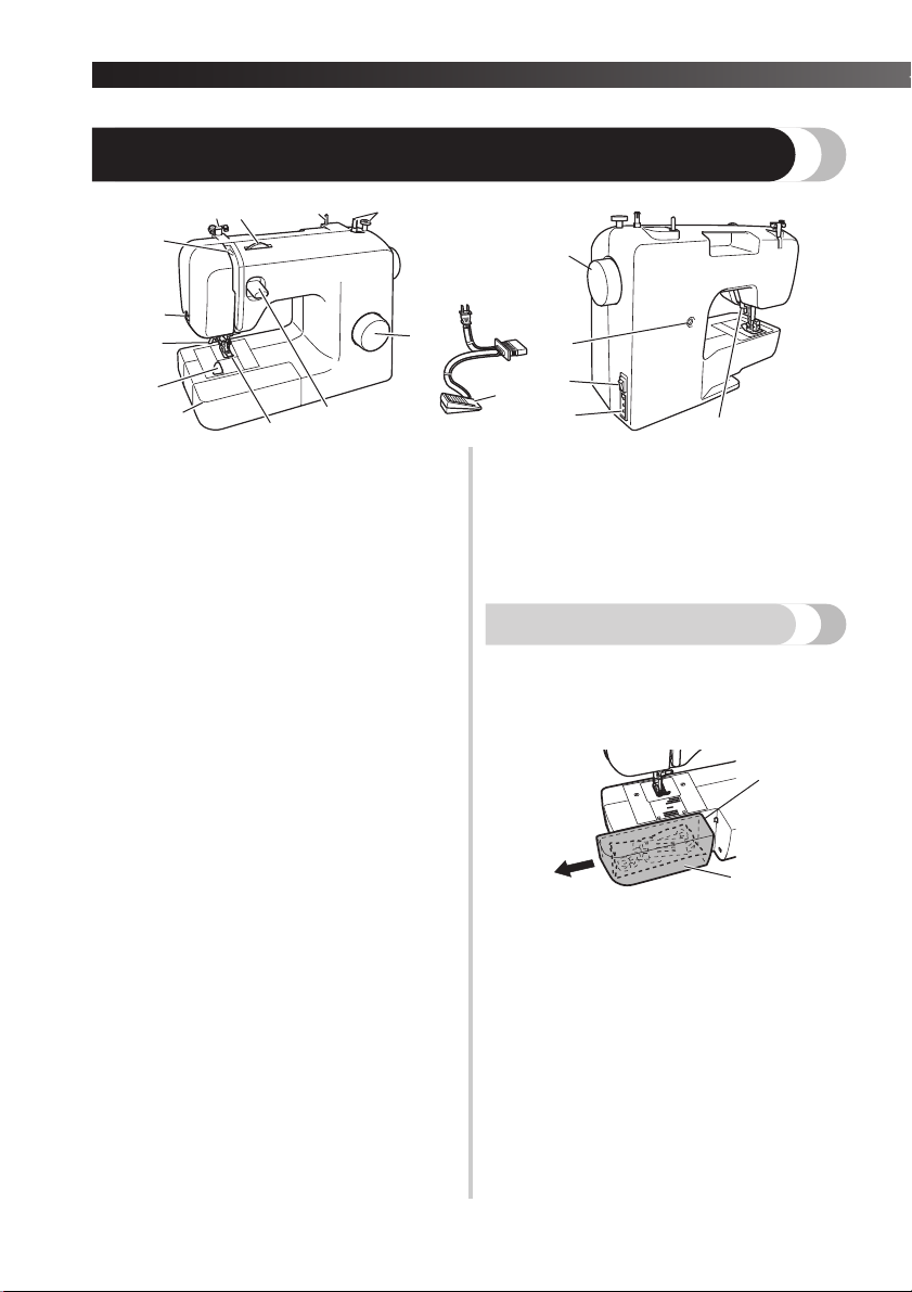
THE MAIN PARTS
1 Bobbin winder (Page 11)
This winds the thread onto the bobbin for use as the
lower thread.
2 Spool pin (Page 11, 15)
This holds the spool of thread.
3 Upper tension-control dial (Page 25)
This controls the tension of the upper thread.
4 Thread guide (Page 11, 15)
This is used when winding the thread onto the
bobbin and then threading the machine.
5 Thread take-up lever (Page 16)
6 Thread cutter (Page 22)
Pass the threads through the thread cutter to cut
them.
7 Needle threader (Page 17)
(This is only available on certain models.)
8 Quick-set bobbin (Page 14, 19)
(This is only available on certain models.)
9 Flat bed attachment with accessory compartment
(Page 5)
0 Presser foot (Page 
A Reverse sewing lever (Page 10)
Push this lever to stitch in the reverse direction.
B Pattern selection dial (Page 9)
Rotate the dial in either direction to choose the
stitch you want.
C Handwheel
Used to manually raise and lower the needle.
D Buttonhole fine-adjustment screw (Page 31)
E Main power and sewing light switch (Page 7)
You can turn the main power and sewing light
switch on and off.
F Foot controller jack / socket (Page 6)
G Presser foot lever (Page 15)
Plug in the foot controller plug and connect the
machine to the power supply.
Used to raise and lower the presser foot.
5
H Foot controller (Page 7)
You can use this to control the sewing speed, and to
start and stop sewing.
Foot Controller: Model KD-1902 for 110/120V area
The foot controller part code differs depending on the
country or region. Contact your dealer or the nearest
authorized service center.
Model KD-2902 for 220/240V area
Flat bed attachment
The accessories can be stored in a compartment inside
the flat bed attachment.
Slide the flat bed attachment to the left to
1
open it.
1 Flat bed attachment
2 Storage compartment

———————————————————————————————————————————————————————————————————————————————————————————————————————————————————————————————————————————————————————————————————————————————————————————————————————————————————————————————————————————————————————————————————————————————
USING YOUR SEWING MACHINE
WARNING
● Use only regular household electricity for the power source. Using other power sources may
result in fire, electric shock, or damage to the machine.
● Make sure that the plugs on the power cord are firmly inserted into the electrical outlet and
the power supply jack on the machine.
● Do not insert the plug on the power cord into an electrical outlet that is in poor condition.
● Turn off the main power and remove the plug in the following circumstances:
• When you are away from the machine
• After using the machine
• When the power fails during use
• When the machine does not operate correctly due to a bad connection or a disconnection
• During electrical storms
CAUTION
● Use only the power cord included with this machine.
● Do not use extension cords or multi-plug adapters with many other appliances plugged in to
them. Fire or electric shock may result.
● Do not touch the plug with wet hands. Electric shock may result.
● When unplugging the machine, always turn off the main power first. Always grasp the plug to
remove it from the outlet. Pulling on the cord may damage the cord, or lead to fire or electric
shock.
● Do not allow the power cord to be cut, damaged, modified, forcefully bent, pulled, twisted,
or bundled. Do not place heavy objects on the cord. Do not subject the cord to heat. These
things may damage the cord and cause fire or electric shock. If the cord or plug is damaged,
take the machine to your authorized dealer for repairs before continuing use.
● Unplug the power cord if the machine is not to be used for a long period of time. Otherwise
a fire may result.
1
Connecting plugs
Connect the foot controller plug to the
1
machine.
Connect the power supply plug to a wall
2
outlet.
● If a power outage occurs while the sewing
machine is being operated, turn off the main
power and unplug the power supply cord.
When restarting the sewing machine, follow
the necessary procedure to correctly operate
the machine.
(For U.S.A. only)
● This appliance has a polarized plug (one
blade wider than the other). To reduce the
risk of electric shock, this plug is intended to
fit in a polarized outlet only one way. If the
plug does not fit fully in the outlet, reverse
the plug.
If it still does not fit, contact a qualified
electrician to install the proper outlet. Do
not modify the plug in any way.
6
KNOWING YOUR SEWING MACHINE —————————————————————————————————————————————————————————————————————————————————————————————————————————————————————————————————————————————————————————————————————————————————
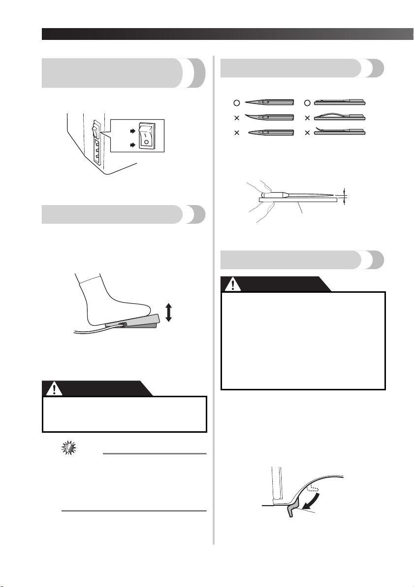
Main power and sewing
light switch
This switch turns the main power and sewing light on or
off.
1 Turn on (toward the ‘I’ mark)
2 Turn off (toward the ‘O’ mark)
Foot controller
When you press the foot controller down lightly, the
machine will run at a low speed. When you press
harder, the machine’s speed will increase. When you
take your foot off the foot controller, the machine will
stop.
1
2
1 Slower
2 Faster
You should make sure that nothing is placed on the foot
controller when the machine is not in use.
CAUTION
● Do not allow pieces of cloth and dust to
build up on the foot controller. Doing so
could cause a fire or an electric shock.
(For U.S.A. only)
● Foot Controller: Model KD-1902
This foot controller can be used on the
machine with product code 885-X11.
The product code is mentioned on the
machine rating plate.
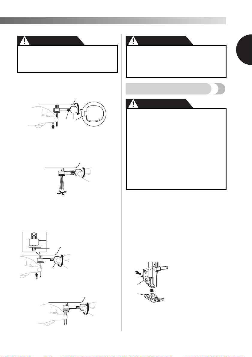
Checking the needle
The sewing needle must always be straight and sharp
for smooth sewing.
■ Checking the needle correctly
Put the flat side of the needle on a flat surface.
Check the needle from the top and the sides.
Dispose of any bent needles safely.
1 Parallel space
2 Level surface (bobbin cover, glass, etc.)
Replacing the needle
● Always turn off the machine before you
change the needle. Otherwise, injuries
may occur if the foot controller is
accidentally pressed and the machine
starts sewing.
● Only use sewing machine needles for
home use. Other needles may bend or
break and cause injury.
● Never sew with a bent needle. A bent
needle will easily break and cause injury.
Turn off the machine.
1
Raise the needle by turning the
2
handwheel toward you
(counterclockwise) so that the mark on
the wheel points up.
Lower the presser foot lever.
3
7
1 Presser foot lever
———————————————————————————————————————————————————————————————————————————————————————————————————————————————————————————————————————————————————————————————————————————————————————————————————————————————————————————————————————————————————————————————————————————————
CAUTION
● Before replacing the needle, place fabric
or paper under the presser foot to
prevent the needle from falling into the
hole in the needle plate.
Hold the needle with your left hand, and
4
then use an oval screwdriver to turn the
needle clamp screw counterclockwise to
remove the needle.
21
1 Use an oval screwdriver
2 Needle clamp screw
• Do not use excessive force when loosening
or tightening the needle clamp screw,
otherwise certain parts of the sewing
machine may be damaged.
With the flat side of the needle toward the
5
back of the machine, insert the needle
until it touches the needle stopper. Next,
tighten the needle clamp using an oval
screwdriver.
CAUTION
● Make sure you insert the needle until it
touches the stopper, and securely tighten
the needle clamp screw with an oval
screwdriver, otherwise the needle may
break or the machine may be damaged.
Changing the presser foot
● Always turn off the machine before you
change the presser foot. If you leave the
power on and step on the controller, the
machine will start and you may be
injured.
● Always use the correct presser foot for
the stitch pattern you have chosen. If
you use the wrong presser foot, the
needle may strike the presser foot and
bend or break, and may cause injury.
● Only use presser feet that have been
designed to be used with this machine.
Using any other presser foot may cause
accident or injury.
You will have to change the presser foot depending on
what you want to sew and how.
Turn off the machine.
1
Raise the presser foot lever.
Raise the needle by turning the
2
handwheel toward you
(counterclockwise) so that the mark on
the wheel points up.
Press the black button at the back of the
3
presser foot holder to release the presser
foot.
1
Install the twin needle in the same way.
1 Use an oval
screwdriver
2 Needle stopper
3 Needle
1
2
3
Put a different presser foot on the needle
4
plate so that the bar on the presser foot is
in line with the slot on the shank.
1 Black button
2 Presser foot holder
3 Presser foot
8

KNOWING YOUR SEWING MACHINE —————————————————————————————————————————————————————————————————————————————————————————————————————————————————————————————————————————————————————————————————————————————————
Lower the presser foot lever and fix the
5
presser foot onto the shank. If the presser
foot is in the correct place, the bar should
snap in.
2
1 Shank
2 Bar
1
THE CONTROLS
Pattern selection dial
CAUTION
● When you use the pattern selection dial
to choose a pattern, raise the needle by
turning the handwheel toward you
(counterclockwise) so that the mark on
the wheel points up. If the needle is in
the down position when you turn the
pattern selection dial, the needle, presser
foot or fabric may be damaged.
To choose a stitch, simply turn the pattern selection dial
in either direction.
■ Presser foot installation orientation
● If the presser foot is not installed with
the correct orientation, the needle may
strike the presser foot, which may bend
or break the needle and cause injury.
Patterns and stitch names
■ 17 Stitches
1
10
9
Pattern
Stitch Name
2
3
11
12
5
4
13
14 15 16 17
Preset Length
(mm (inch))
Preset Width
(mm (inch))
6
7
Reference
Page
8
9
1 Pattern selection dial
2 Chosen pattern number
4-STEP AUTOMATIC
BUTTONHOLE
2
STRAIGHT STITCH
(Center Needle
Position)
3
STRAIGHT STITCH
(Center Needle
Position)
0.5 (1/32)
30
5 (3/16)
1.6 (1/16)
26, 34
—
1.8 (1/16)
26,34
—

———————————————————————————————————————————————————————————————————————————————————————————————————————————————————————————————————————————————————————————————————————————————————————————————————————————————————————————————————————————————————————————————————————————————
Pattern
Stitch Name
4
STRAIGHT STITCH
(Center Needle
Position)
5
STRAIGHT STITCH
(Center Needle
Position)
6
STRAIGHT STITCH
(Center Needle
Position)
STRAIGHT STITCH
(Left Needle Position)
ZIGZAG STITCH 1.5 (1/16)
ZIGZAG STITCH 3 (1/8)
10
ZIGZAG STITCH 5 (3/16)
ZIGZAG (SATIN)
STITCH
12
SHELL TUCK STITCH 5 (3/16)
13
ELASTIC STITCH 5 (3/16)
Preset Length
(mm (inch))
Preset Width
(mm (inch))
2 (1/16)
—
2.5 (3/32)
—
4 (3/16)
—
2.5 (3/32)
—
0.7 (1/32)
1.5 (1/16)
2 (1/16)
0.5 (1/32)
5 (3/16)
2 (1/16)
1 (1/16)
Reference
Page
26, 34
26, 33, 34,
36
26, 34
26, 34
26, 32, 35,
36
26, 32, 35,
36
26, 32, 35,
36
26, 35
28
28
Pattern
Stitch Name
14
STRETCH BLIND
HEM STITCH
15
SCALLOP STITCH 5 (3/16)
DOUBLE ACTION
STITCH
BRIDGING STITCH 5 (3/16)
Preset Length
(mm (inch))
Preset Width
(mm (inch))
1 (1/16)
5 (3/16)
0.5 (1/32)
1.2 (1/16)
5 (3/16)
1.2 (1/16)
Reference
Page
27, 36
29
29
29
Reverse sewing lever
You can use reverse sewing for back tacking and
reinforcing seams.
To sew in reverse, push the reverse sewing lever in as
far as possible and hold it in that position while you
lightly push the foot controller. To sew forward, release
the reverse sewing lever. The machine will then sew
forward.
The length of reverse stitches is fixed at 2 mm
(1/16 inch).
1
1 Reverse sewing lever
1
10
KNOWING YOUR SEWING MACHINE —————————————————————————————————————————————————————————————————————————————————————————————————————————————————————————————————————————————————————————————————————————————————
1 Pull the thread
in completely.
THREADING THE MACHINE
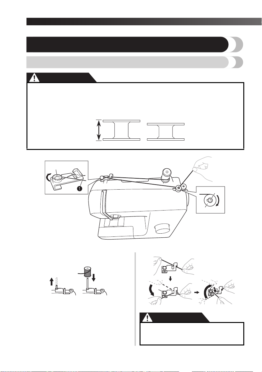
Winding the bobbin
CAUTION
● We designed the bobbin that comes with this machine. If you use bobbins from other models,
the machine will not work properly. Only use the bobbin that comes with this machine or
bobbins of the same type (part code: SA156, SFB: XA5539-151). Using other bobbins may
cause damage to the machine.
11.5 mm
(7/16 inch)
This model Other models
Actual size
1 Pre-tension disk 2 Bobbin winder shaft 3 Bobbin
Pull up the spool pin and put a spool of
1
thread on this pin.
While holding the thread from the spool
2
with your right hand, pass the thread
toward you, in the groove on the thread
guide. Then, pass the thread around the
pre-tension disk and pull the thread in
completely.
11
1 Pre-tension disk
● If the spool of thread is in the wrong
place, or is set incorrectly, the thread
may tangle on the spool pin.

———————————————————————————————————————————————————————————————————————————————————————————————————————————————————————————————————————————————————————————————————————————————————————————————————————————————————————————————————————————————————————————————————————————————
Pass the end of the thread through the
3
hole on the bobbin from the inside of the
bobbin.
Put the bobbin onto the bobbin winder
4
shaft and slide the bobbin winder shaft to
the right. Turn the bobbin clockwise, by
hand, until the spring on the shaft slides
into the notch of the bobbin.
• Make sure to pull out 7 to 10 cm (3-4 inches)
of thread from the hole on the bobbin.
1 Spring on the shaft
2 Notch
3 7-10 cm (3 – 4 inches)
● Pull the thread taut and hold the end of
the thread straight up. If the thread is too
short, not pulled taut or held at an angle,
injuries may occur when the thread is
wound around the bobbin.
Trim the excess thread above the bobbin.
7
• Leave 1 cm (1/2 inch) of thread from the hole
on the bobbin.
1
1 1 cm (1/2 inch)
CAUTION
● Make sure you follow the instructions
carefully. If you do not cut the excess
thread completely before winding the
bobbin, when the thread runs low it may
tangle around the bobbin and cause the
needle to break.
Press the foot controller to start.
8
When the bobbin seems full and begins
9
spinning slowly, take your foot off the foot
controller.
Cut the thread, slide the bobbin winder
0
shaft to the left and remove the bobbin.
1
5
6
Turn on the machine.
While holding the end of the thread,
gently press the foot controller to wind
the thread around the bobbin a few times.
Then stop the machine.
● When the sewing machine is started or the
handwheel is turned after winding the
thread around the bobbin, the machine will
make a clicking sound; this is not a
malfunction.
● The needle bar does not move when you
slide the bobbin winder shaft to the right.
12
KNOWING YOUR SEWING MACHINE —————————————————————————————————————————————————————————————————————————————————————————————————————————————————————————————————————————————————————————————————————————————————
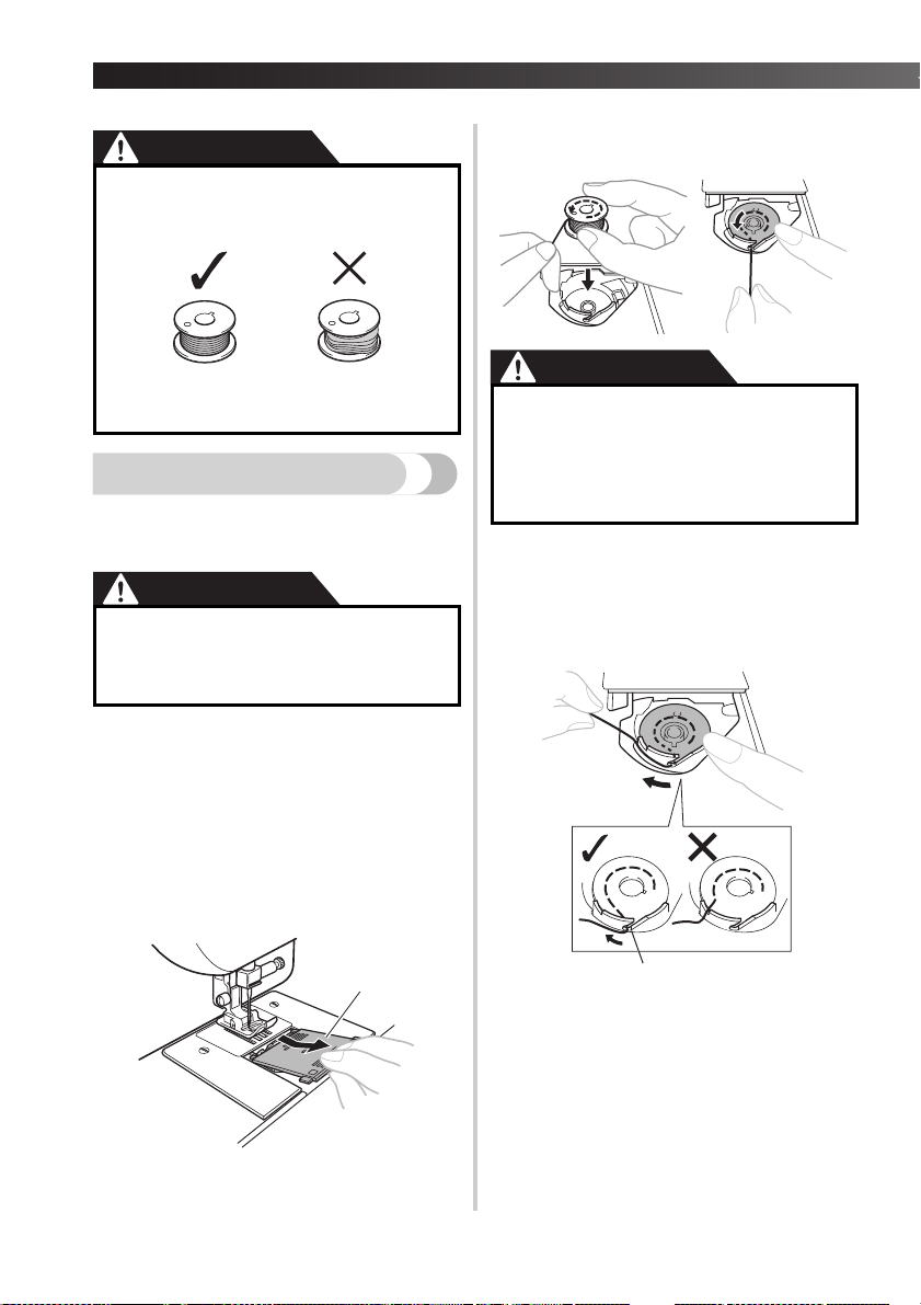
Put the bobbin in so the thread comes out
4
CAUTION
● Not winding the bobbin properly may
in the direction shown by the arrow.
cause the thread tension to loosen, and
may break the needle.
1 Wound evenly
2 Wound poorly
Lower threading
2
Install the bobbin wound with thread.
• For more details on using the quick-set
bobbin, see page 14.
CAUTION
● Make sure you turn off the machine
while threading. If you accidentally step
on the foot controller and the machine
starts to sew, you could be injured.
Prepare the bobbin wound properly
1
before threading the lower thread.
• See page 11 for the details about bobbin
winding.
Raise the needle by turning the
2
handwheel toward you
(counterclockwise) and raise the presser
foot lever.
Remove the bobbin cover by sliding it and
3
lift toward you.
1
CAUTION
● Make sure you set the bobbin so the
thread unrolls in the right direction. If
the thread unrolls in the wrong
direction, it may cause the thread
tension to be incorrect or break the
needle.
Hold the end of the thread, push the
5
bobbin down with your finger, and then
pass the thread through the slit, as shown.
• If the thread is not correctly inserted through
the tension-adjusting spring of the bobbin
case, it may cause incorrect thread tension.
1 Tension-adjusting spring
13
1 Bobbin cover
Loading…