
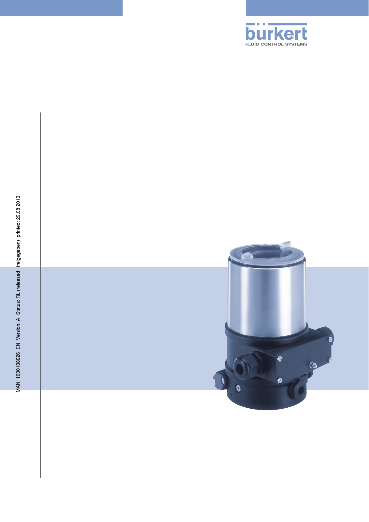
Type 8692, 8693
Positioner TopControl
Process Controller TopControl
Electropneumatic positioner
Electropneumatic process controller
Operating Instructions
Bedienungsanleitung
Manuel d‘ utilisation
We reserve the right to make technical changes without notice.
Technische Änderungen vorbehalten.
Sous réserve de modifications techniques.
© 2008-2011 Bürkert Werke GmbH
Operating Instructions 1111/01_EU-ML_00806169 / Original DE

Type 8692, 8693
Table of contents
Positioner Type 8692, 8693
Table of ConTenTs
GENERAL INFORMATION AND SAFETY INSTRUCTIONS ……………………………………………………………………………………….7
1. Operating instructions ………………………………………………………………………………………………………………………………………8
2. Authorized use ……………………………………………………………………………………………………………………………………………………9
3. Basic safety instructions ……………………………………………………………………………………………………………………………….10
4. General Information………………………………………………………………………………………………………………………………………..11
DESCRIPTION OF SYSTEM ……………………………………………………………………………………………………………………………………………….13
5. Function of the positioner and combination with valve types …………………………………………………………..14
6. Structure of the positioner …………………………………………………………………………………………………………………………..17
7. Type 8692 positioner with position controller ………………………………………………………………………………………..20
8. Type 8693 positioner with process controller ………………………………………………………………………………………..24
9. Interfaces of the positioner for the multipole model …………………………………………………………………………..28
10. Interfaces of the positioner for the models with cable gland …………………………………………………………..29
11. Technical Data ………………………………………………………………………………………………………………………………………………….30
CONTROL AND DISPLAY ELEMENTS, OPERATING MODES ……………………………………………………………………………….35
12. Control and display elements ……………………………………………………………………………………………………………………..36
13. Operating modes …………………………………………………………………………………………………………………………………………….39
14. Operating Levels ……………………………………………………………………………………………………………………………………………..43
INSTALLATION ………………………………………………………………………………………………………………………………………………………………………..45
15. Installation …………………………………………………………………………………………………………………………………………………………47
16. Fluid connection ………………………………………………………………………………………………………………………………………………57
17. Electrical Connection 24 V DC with circular plug-in connector (multi-pole model) …………………..59
18. Electrical Connection 24 V DC with Cable Gland ………………………………………………………………………………….67
19. Initial start-up …………………………………………………………………………………………………………………………………………………… 72
english
3
Type 8692, 8693
Table of contents
START-UP AND OPERATION OF THE POSITION CONTROLLER TYPE 8692 …………………………………………………77
20. Starting up and installing the position controller Type 8692 …………………………………………………………….79
21. Operation of the position controller ………………………………………………………………………………………………………….87
22. Configuring the auxiliary functions ……………………………………………………………………………………………………………92
START-UP AND OPERATION OF THE POSITION CONTROLLER TYPE 8693 ……………………………………………… 125
23. Starting up and setting up the process controller Type 8693 ……………………………………………………….. 127
24. Operation of the process controller ……………………………………………………………………………………………………….149
25. Auxiliary functions for the process controller ……………………………………………………………………………………..154
PROFIBUS-DP ……………………………………………………………………………………………………………………………………………………………………… 173
26. General Information……………………………………………………………………………………………………………………………………..174
27. Technical Data ………………………………………………………………………………………………………………………………………………. 174
28. Safety Settings if the Bus Fails ……………………………………………………………………………………………………………….. 175
29. Interfaces ………………………………………………………………………………………………………………………………………………………..175
30. Electrical connections …………………………………………………………………………………………………………………………………176
31. Settings on the positioner …………………………………………………………………………………………………………………………. 179
32. Functional Deviations from the Standard Model ……………………………………………………………………………….. 184
33. Configuration in the Profibus-DP Master ……………………………………………………………………………………………… 184
34. Bus Status Display ………………………………………………………………………………………………………………………………………. 187
35. Configuration with Siemens Step7 ………………………………………………………………………………………………………… 188
DEVICENET …………………………………………………………………………………………………………………………………………………………………………… 191
36. General Information……………………………………………………………………………………………………………………………………..193
37. Definition of Terms ……………………………………………………………………………………………………………………………………….193
38. Technical Data ………………………………………………………………………………………………………………………………………………. 194
39. Safety Settings if the Bus Fails ……………………………………………………………………………………………………………….. 195
40. Interfaces ……………………………………………………………………………………………………………………………………………………….. 195
41. Electrical connections …………………………………………………………………………………………………………………………………196
42. Settings on the positioner in the Main Menu ………………………………………………………………………………………. 200
43. Functional Deviations from the Standard Model ……………………………………………………………………………….. 203
44. Configuration of the Process Data …………………………………………………………………………………………………………. 204
4
english
Type 8692, 8693
Table of contents
45. Bus Status Display ………………………………………………………………………………………………………………………………………. 207
46. Configuration Example 1 …………………………………………………………………………………………………………………………… 208
47. Configuration Example 2 …………………………………………………………………………………………………………………………… 211
MAINTENANCE AND TROUBLESHOOTING ………………………………………………………………………………………………………………213
48. Maintenance ………………………………………………………………………………………………………………………………………………….. 214
49. Error messages and malfunctions Type 8692 …………………………………………………………………………………….. 216
50. Error messages and malfunctions Type 8693 …………………………………………………………………………………….. 218
DISASSEMBLY …………………………………………………………………………………………………………………………………………………………………….. 223
51. Disassembly ………………………………………………………………………………………………………………………………………………….. 224
PACKAGING, STORAGE AND DISPOSAL ………………………………………………………………………………………………………………….227
52. Packaging and transport ……………………………………………………………………………………………………………………………. 228
53. Storage ……………………………………………………………………………………………………………………………………………………………. 228
54. Disposal ………………………………………………………………………………………………………………………………………………………….. 228
ACCESSORIES……………………………………………………………………………………………………………………………………………………………………..229
55. Accessories ……………………………………………………………………………………………………………………………………………………. 230
GENERAL RULES (APPENDIX)………………………………………………………………………………………………………………………………………231
56. Selection criteria for continuous valves ……………………………………………………………………………………………….. 232
57. Properties of PID controllers ……………………………………………………………………………………………………………………. 234
58. Adjustment rules for PID controllers ……………………………………………………………………………………………………… 240
OPERATING STRUCTURE OF THE POSITIONER (APPENDIX) …………………………………………………………………………245
59. Operating Structure …………………………………………………………………………………………………………………………………….. 246
TABLES FOR CUSTOMER-SPECIFIC SETTINGS (APPENDIX) …………………………………………………………………………253
60. Settings of the freely programmable characteristic Type 8692 and Type 8693 ……………………….254
61. Set parameters of the process controller Type 8693 ………………………………………………………………………..255
MASTERCODE (APPENDIX) …………………………………………………………………………………………………………………………………………. 257
62. Mastercode …………………………………………………………………………………………………………………………………………………….. 258
english
5

Type 8692, 8693
Table of contents
6
english

Type 8692, 8693
General information and safety instructions
Table of ConTenTs
1. OPERATING INSTRUCTIONS ……………………………………………………………………………………………………………………………………..8
1.1. Symbols ………………………………………………………………………………………………………………………………………………………………..8
2. AUTHORIZED USE ………………………………………………………………………………………………………………………………………………………..9
2.1. Restrictions ………………………………………………………………………………………………………………………………………………………….9
3. BASIC SAFETY INSTRUCTIONS …………………………………………………………………………………………………………………………….10
4. GENERAL INFORMATION ………………………………………………………………………………………………………………………………………….11
4.1. Contact address ………………………………………………………………………………………………………………………………………………11
4.2. Warranty ……………………………………………………………………………………………………………………………………………………………..11
4.3. Master code ………………………………………………………………………………………………………………………………………………………11
4.4. Information on the internet …………………………………………………………………………………………………………………………..11
english
7
Type 8692, 8693
General Information
Safety Instructions
1. OPERATING INSTRUCTIONS
The operating instructions describe the entire life cycle of the device. Keep these instructions in a location which is
easily accessible to every user and make these instructions available to every new owner of the device.
WARNING!
The operating instructions contain important safety information!
Failure to observe these instructions may result in hazardous situations.
• The operating instructions must be read and understood.
1.1. Symbols
DANGER!
Warns of an immediate danger!
• Failure to observe the warning may result in a fatal or serious injury.
WARNING!
Warns of a potentially dangerous situation!
• Failure to observe the warning may result in serious injuries or death.
CAUTION!
Warns of a possible danger!
• Failure to observe this warning may result in a moderately severe or minor injury.
NOTE!
Warns of damage to property!
• Failure to observe the warning may result in damage to the device or the equipment.
Indicates important additional information, tips and recommendations.
refers to information in these operating instructions or in other documentation.
designates a procedure which you must carry out.
8
english
Type 8692, 8693
General Information
Safety Instructions
2. AUTHORIZED USE
Incorrect use of the positioner Type 8692 and Type 8693 may be a hazard to people, nearby equipment
and the environment.
The device is designed to be mounted on pneumatic actuators of process valves for the control of media.
• Do not expose the device to direct sunlight.
• Use according to the permitted data, operating conditions and conditions of use specified in the contract
documents and operating instructions, as described in chapter “Description of system” — “11. Technical
data“ in this manual and in the valve manual for the respective pneumatically actuated valve.
• The device may be used only in conjunction with third-party devices and components recommended and
authorised by Bürkert.
• In view of the large number of options for use, it is essential prior to installation to study and, if necessary, to
test whether the positioner is suitable for the specific application case.
• Correct transportation, correct storage and installation and careful use and maintenance are essential for
reliable and problem-free operation.
• Use the positioner Type 8692 and Type 8693 only as intended.
2.1. Restrictions
If exporting the system/device, observe any existing restrictions.
english
9
Type 8692, 8693
General Information
Safety Instructions
3. BASIC SAFETY INSTRUCTIONS
These safety instructions do not make allowance for any
• contingencies and events which may arise during the installation, operation and maintenance of the devices.
• local safety regulations; the operator is responsible for observing these regulations, also with reference to the
installation personnel.
DANGER!
Danger – high pressure!
• Before loosening the lines and valves, turn off the pressure and vent the lines.
Risk of electric shock!
• Before reaching into the device or the equipment, switch off the power supply and secure to prevent
reactivation!
• Observe applicable accident prevention and safety regulations for electrical equipment!
General hazardous situations.
To prevent injury, ensure that:
• the system cannot be activated unintentionally.
• Installation and repair work may be carried out by authorised technicians only and with the appropriate tools.
• After an interruption in the power supply or pneumatic supply, ensure that the process is restarted in a defined
or controlled manner.
• The device may be operated only when in perfect condition and in consideration of the operating instructions.
• The general rules of technology apply to application planning and operation of the device.
• Do not put any loads on the body (e.g. by placing objects on it or standing on it).
• Do not make any external modifications to the device bodies. Do not paint the body parts or screws.
NOTE!
Electrostatic sensitive components / modules!
• The device contains electronic components which react sensitively to electrostatic discharge (ESD). Contact
with electrostatically charged persons or objects is hazardous to these components. In the worst case scenario,
they will be destroyed immediately or will fail after start-up.
10
• Observe the requirements in accordance with EN 100 015 — 1 and 5 — 2 to minimise or avoid the possibility of
damage caused by sudden electrostatic discharge!
• Also ensure that you do not touch electronic components when the power supply voltage is present!
The positioners Type 8692 and Type 8693 were developed with due consideration given to the accepted
safety rules and is state-of-the-art. However, dangers can still arise.
Failure to observe this operating manual and its operating instructions as well as unauthorized tampering with
the device release us from any liability and also invalidate the warranty covering the devices and accessories!
english

Type 8692, 8693
General Information
Safety Instructions
4. GENERAL INFORMATION
4.1. Contact address
Germany
Bürkert Fluid Control System
Sales Center
Chr.-Bürkert-Str. 13-17
D-74653 Ingelfingen
Tel. + 49 (0) 7940 — 10 91 111
Fax + 49 (0) 7940 — 10 91 448
E-mail: info@de.buerkert.com
International
Contact addresses can be found on the final pages of the printed operating instructions.
And also on the Internet at:
www.burkert.com
4.2. Warranty
The warranty is only valid if the positioner Type 8692 and Type 8693 is used as intended in accordance with the
specified application conditions.
4.3. Master code
Operation of the device can be locked via a freely selectable user code. In addition, there is a non-changeable master
code with which you can perform all operator control actions on the device. This 4-digit master code can be found
in the Appendix of these operating instructions in the chapter entitled “Master code”.
If required, cut out the code and keep it separate from these operating instructions.
4.4. Information on the internet
The operating instructions and data sheets for Type 8694 can be found on the Internet at:
www.burkert.com
english
11

Type 8692, 8693
General Information
Safety Instructions
12
english
Type 8692, 8693
Description of system
Table of ConTens
5. FUNCTION OF THE POSITIONER AND COMBINATION WITH VALVE TYPES ………………………………………….14
5.1. Models of the positioner ……………………………………………………………………………………………………………………………….15
5.2. Features of the valve types ………………………………………………………………………………………………………………………….16
6. STRUCTURE OF THE POSITIONER ………………………………………………………………………………………………………………………17
6.1. Representation …………………………………………………………………………………………………………………………………………………17
6.2. Features ……………………………………………………………………………………………………………………………………………………………..18
6.3. Function diagram of the positioner with single-acting actuator ………………………………………………………19
7. TYPE 8692 POSITIONER WITH POSITION CONTROLLER ……………………………………………………………………………..20
7.1. Schematic representation of the positioner Type 8692 ………………………………………………………………………21
7.2. Properties of the position controller software ……………………………………………………………………………………….22
8. TYPE 8693 POSITIONER WITH PROCESS CONTROLLER ……………………………………………………………………………..24
8.1. Schematic representation of the process control ………………………………………………………………………………..25
8.2. Functions of the process controller software ………………………………………………………………………………………..26
9. INTERFACES OF THE POSITIONER FOR THE MULTIPOLE MODEL …………………………………………………………..28
10. INTERFACES OF THE POSITIONER FOR THE MODELS WITH CABLE GLAND ………………………………………29
11. TECHNICAL DATA ………………………………………………………………………………………………………………………………………………………..30
11.1. Safety positions after failure of the electrical or pneumatic auxiliary power ……………………………….30
11.2. Factory settings of the positioner ………………………………………………………………………………………………………………31
11.3. Specifications of the positioner ………………………………………………………………………………………………………………….32
11.3.1. Conformity ……………………………………………………………………………………………………………………………….32
11.3.2. Standards ………………………………………………………………………………………………………………………………..32
11.3.3. Operating conditions ……………………………………………………………………………………………………………… 32
11.3.4. Mechanical data ……………………………………………………………………………………………………………………… 32
11.3.5. Electrical data ………………………………………………………………………………………………………………………….32
11.3.6. Pneumatic Data ………………………………………………………………………………………………………………………33
11.3.7. Type label ………………………………………………………………………………………………………………………………..34
english
13
Type 8692, 8693
Description of system
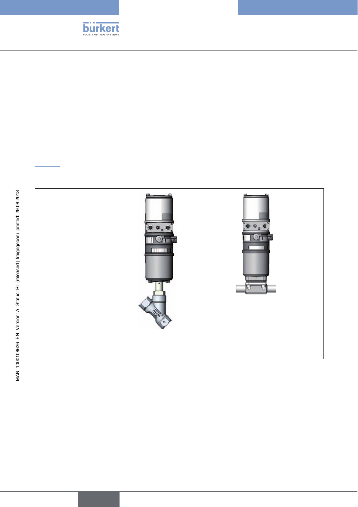
5. FUNCTION OF THE POSITIONER AND
COMBINATION WITH VALVE TYPES
Positioners Type 8692 and Type 8693 are electropneumatic positioner for pneumatically actuated control valves
with single-acting or double-acting actuators.
Together with the pneumatic actuator the positioner forms an optical and functional unit.
The control valve systems can be used for a wide range of control tasks in fluid technology and, depending on the
application conditions, different process valves belonging to series 2300 or 2103 from the Bürkert range can be
combined with the positioner. Angle-seat valves, diaphragm valves or ball valves fitted with a control cone are suitable.
“Figure 1” shows an overview of the possible combinations of positioner and different pneumatically actuated valves.
Different actuator sizes and valve nominal widths, not illustrated here, are available for each type. More precise
specifications can be found on the respective data sheets. The product range is being continuously expanded.
Positioner
Type 8692
Type 8693
with slanted seat valve
Type 2300
Figure 1: Overview of possible combinations
with diaphragm valve
Type 2103
14
english

Type 8692, 8693
Description of system,
5.1. Models of the positioner
The positioner is available in 2 versions:
Type 8692 — Positioner with positioning control
The position of the actuator (stroke) is regulated according to the position set-point value. The position set-point
value is specified by an external uniform signal (or via field bus).
Type 8693 — Positioner with process control
The positioner is linked to a control circuit. The position set-point value of the valve is calculated from the process
set-point value and the actual process value via the control parameters (PID controller). The process set-point value
can be set by an external signal.
Pneumatically actuated piston actuators and rotary actuators can be used as a actuator. Both single-acting and
double-acting actuators are offered in combination with the positioner.
For single-acting actuators, only one chamber is aerated and deaerated during actuation. The generated pressure
works against a spring. The piston moves until there is an equilibrium of forces between compressive force and
spring force.
For double-acting actuators the chambers on both sides of the piston are pressurised. In this case, one chamber is
aerated when the other one is deaerated and vice versa. In this design, no spring is installed in the actuator.
english
15
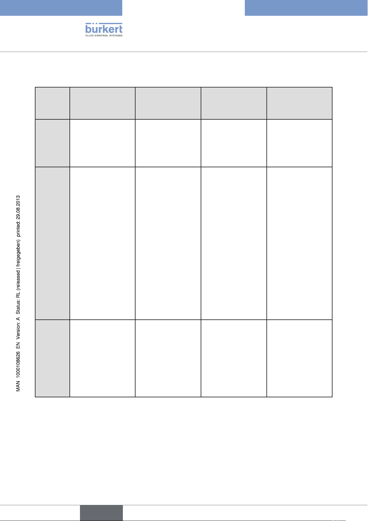
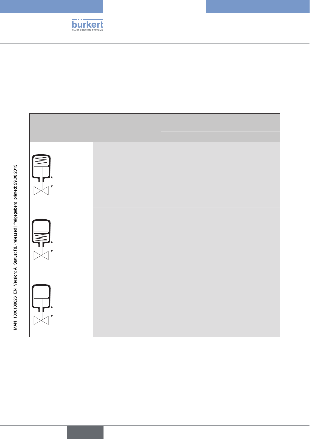
5.2. Features of the valve types
Type 8692, 8693
Description of system
Types
Features
Slanted seat control
valves / screw-down
stop globe control
valves
• 2702
• 2712
• 2300
• 2301
• incoming flow under
seat
• closes smoothly
• straight flow path of
the medium
• self-adjusting
stuffing box for high
leak-tightness
Diaphragm valves Ball valves Flap valves
• 2730
• 2103
• 2731
• medium is hermetically separated from
the actuator and
environment
• cavity-free and selfdraining body design
• any flow direction
with low-turbulence
flow
• steam-sterilizable
• CIP-compliant
• closes smoothly
• 2652
• 2655
• 2658
• scrapable
• minimum dead
space
• unaffected by
contamination
• little pressure loss
compared to other
valve types
• seat and seal can
be exchanged in the
three-piece ball valve
when installed
• 2672
• 2675
• unaffected by
contamination
• little pressure loss
compared to other
valve types
• inexpensive
• low construction
volume
Typical
media
Table 1: Features of the valve types
• water, steam and
gases
• alcohols, oils, propellants, hydraulic
fluids
• salt solutions, lyes
(organic)
• solvents
• actuator and diaphragm can be
removed when the
body is installed
• neutral gases and
liquids
• contaminated,
abrasive and
aggressive media
• media of higher
viscosity
Information
Can be used as
process controller only
• neutral gases and
liquids
• clean water
• slightly aggressive
media
• neutral gases and
liquids
• slightly aggressive
media
16
english
Type 8692, 8693
Description of system,
6. STRUCTURE OF THE POSITIONER
The positioners Type 8692 and Type 8693 consist of the micro-processor controlled electronics, the position measuring system and the control system.
The appliance is designed using three-wire technology. Operation of the positioner is controlled by four keys and a
128×64 dot matrix graphic display.
The pneumatic control system for single or double-acting actuators consists of two or four solenoid valves.
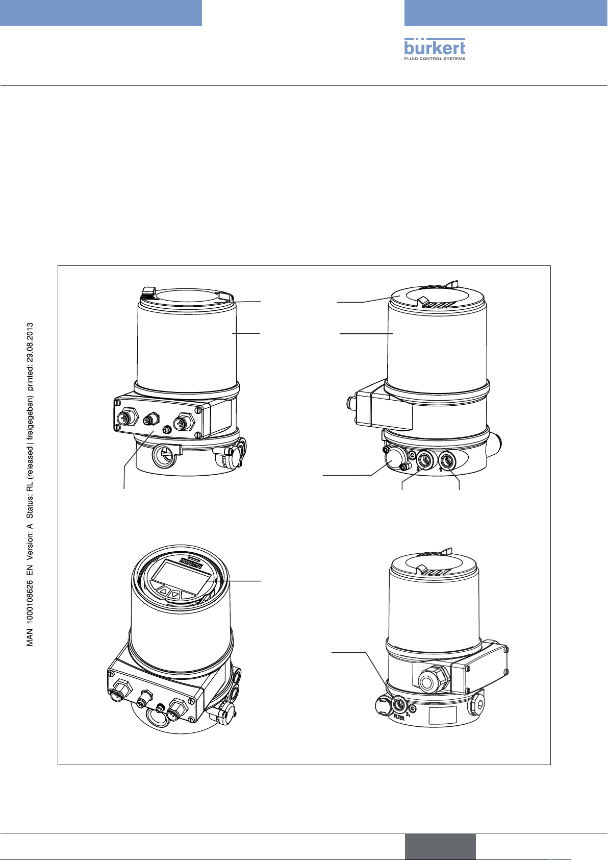
6.1. Representation
Transparent cap
Body casing
Electrical connection module
(here with circular plug-in connectors)
Pressure limiting valve
(for protection against too
high internal pressure in
case of error)
Exhaust air connection
(label: 3)
Control module with
display and keys
(View without transparent cap)
Additional
Exhaust air connection
(connection: 3.1)
only with Type 23xx
and 2103
with pilot-operated
control system for high
air output (actuator size
ø 125 / 130)
Pilot air port
(label: 1)
Figure 2: Structure
17
english
Type 8692, 8693
Description of system
6.2. Features
• Models
for single-acting or double-acting valve actuators.
• Position measuring system
Non-contact and therefore non-wearing position measuring system.
• Microprocessor-controlled electronics
for signal processing, control and valve control.
• Control module
Operation of the device is controlled by four keys. The 128×64 dot matrix graphics display enables you to
display the set-point or actual value and to configure and parameterize via menu functions.
• Control system
The control system consists of 2 solenoid valves for single-acting actuators or four solenoid valves for doubleacting actuators. In single-acting actuators, one valve serves for the aeration and another for the deaeration
of the pneumatic piston actuator. Double-acting actuators feature 2 valves for aeration and deaeration. The
solenoid valves operate according to the rocker principle and are controlled with a PWM voltage via the controller. Doing so achieves a higher flexibility with regard to actuator volume and final control speed. The directaction model has an orifice of DN 0.6. On larger pneumatic actuators the solenoid valves feature diaphragm
reinforcers to increase the maximum flow and therefore improve the dynamics (DN 2.5).
• Position feedback (optional)
One inductive proximity switch.
When the valve reaches an upper or a lower position, this can be relayed e.g. to a PLC via binary outputs. By
means of set-screws, the operator can change the inductive proximity switch or limit positions.
• Pneumatic interfaces
1/4” connections with different thread forms
(G, NPT)
Hose plug-in connection
• Electrical interfaces
Circular plug-in connector or cable gland
18
• Body
The body of the positioner is protected from excessively high internal pressure, e.g. caused by leaks, by a
pressure limiting valve.
english
Type 8692, 8693
Description of system,
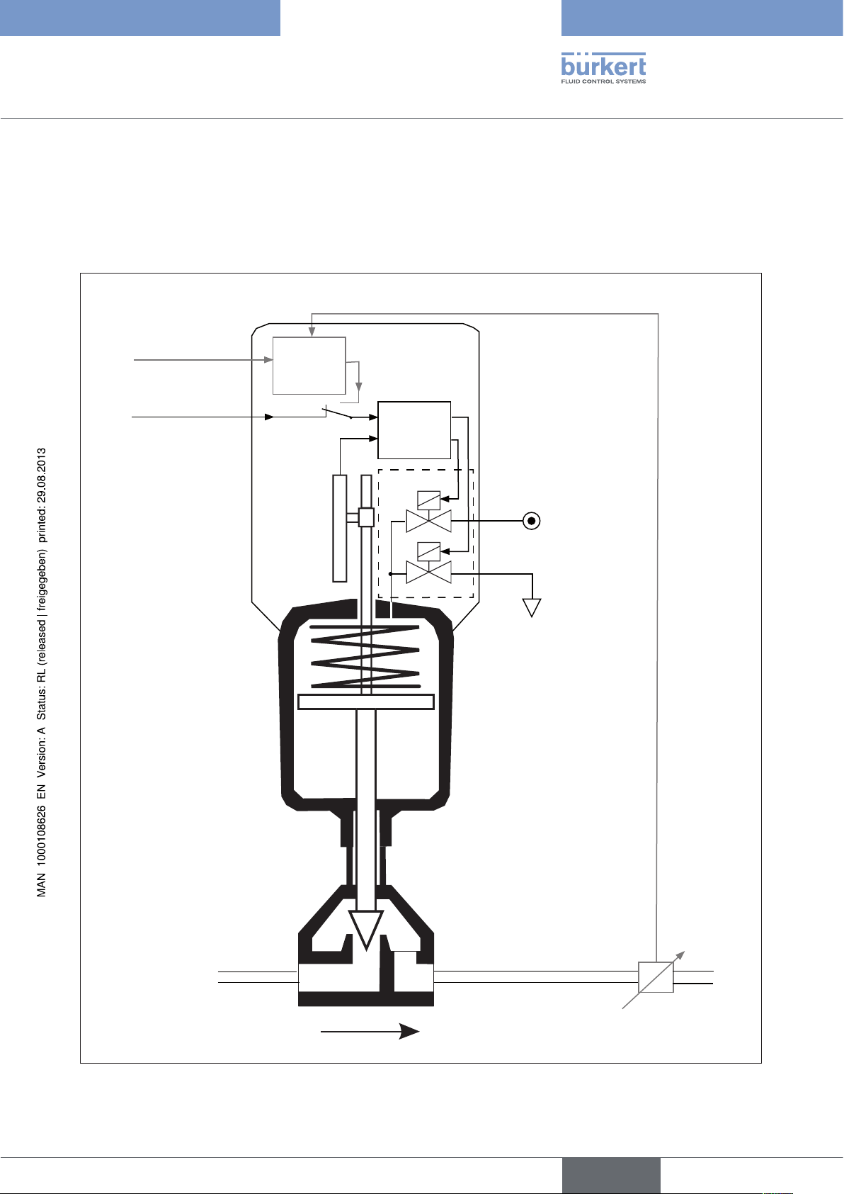
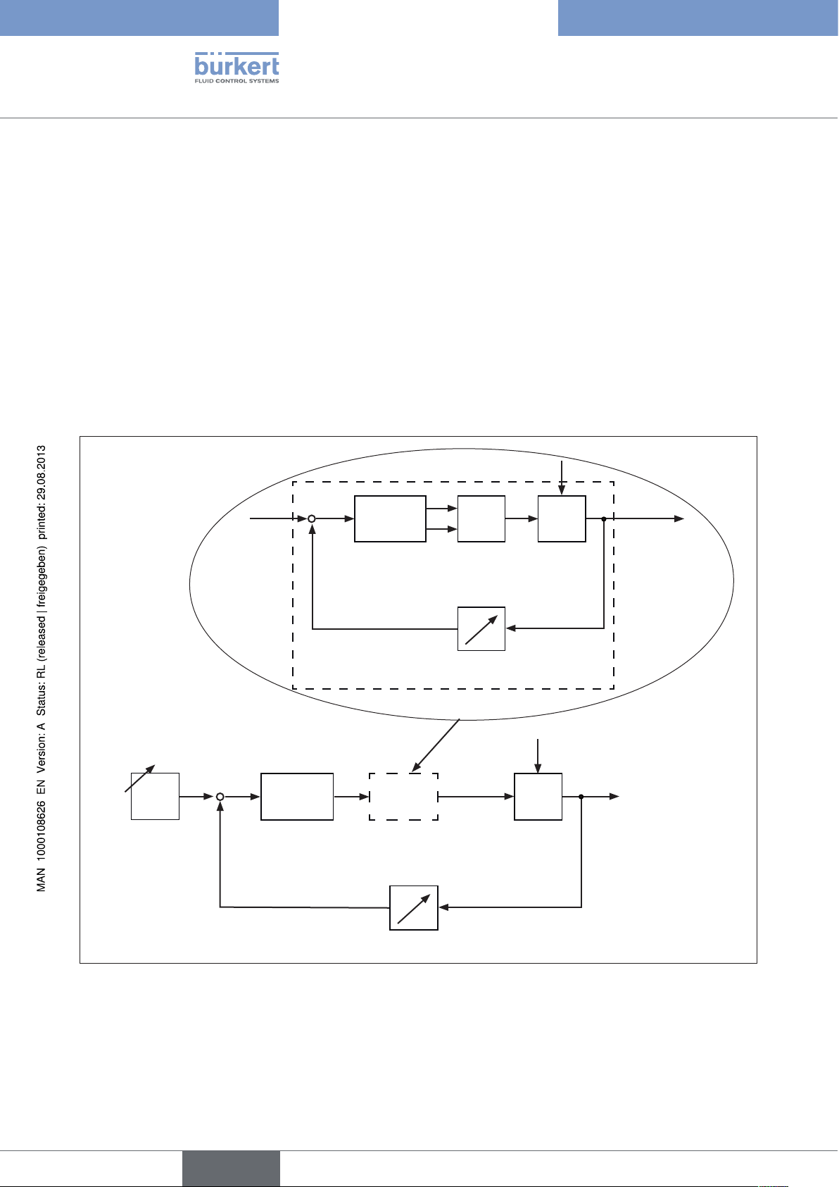
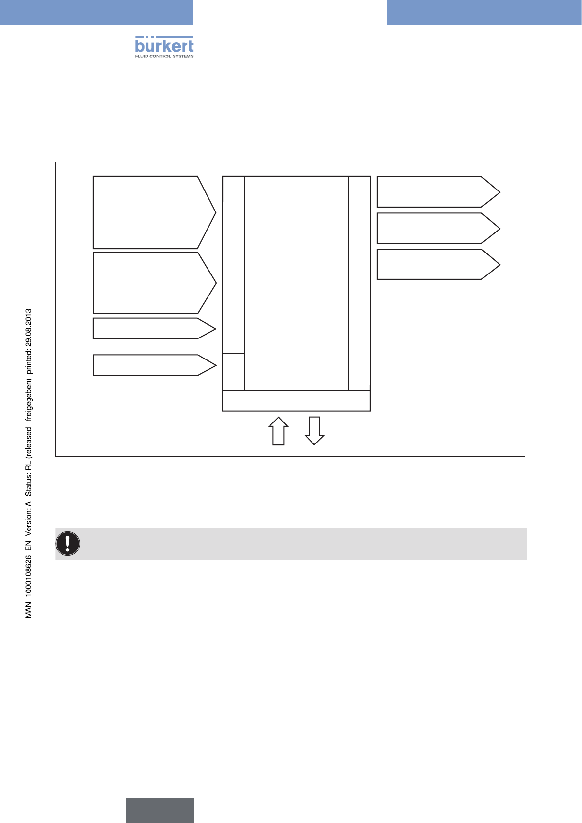
6.3. Function diagram of the positioner with single-
acting actuator
The black lines describe the function of the position controller (Type 8692). The process controller (Type 8693)
includes the position controller and the functions which are illustrated in grey.
Process actual value
Process set-point
value
External position
set-point value
Positioner
Process
controller
Actual
position
Position
measuring
system
Nominal position
Position
controller
Control system
1
2
Control system
1: Aeriation valve
2: Bleed valve
Compressedair supply
Pneumatic actuator
(single-acting)
Valve
Figure 3: Function diagram
Exhaust air
Sensor
Process actual value
(flow, pressure, level,
temperature, et cetera.)
19
english
Type 8692, 8693
Description of system
7. TYPE 8692
POSITIONER WITH POSITION CONTROLLER
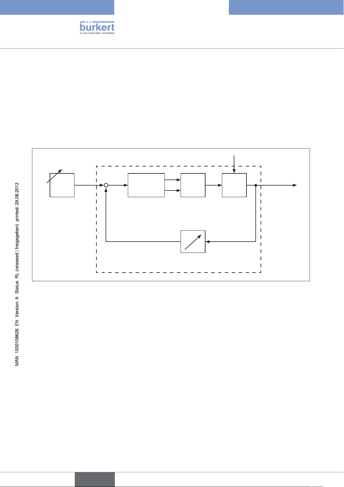
The position measuring system records the current position (POS) of the pneumatic actuator. The position controller
compares this actual position value with the set-point value (CMD), which is definable as norm signal. In case of
a control deviation (Xd1), a pulse-width modulated voltage signal is sent to the control system as a manipulated
variable. If there is a positive control difference in single-acting actuators, the air inlet valve is controlled via output
B1. If the control difference is negative, the bleed valve is controlled via output E1. In this way the position of the
actuator is changed until control difference is 0. Z1 represents a disturbance variable.
Z1
CMD Xd1
+
—
PositionerPosition set-
point value
Position control circuit
Figure 4: Signal flow plan of position controller
B1
E1
Control system
solenoid valves
POS
Position measuring
P
K
Continuous
valve
Valve opening
20
english
Type 8692, 8693
Description of system,
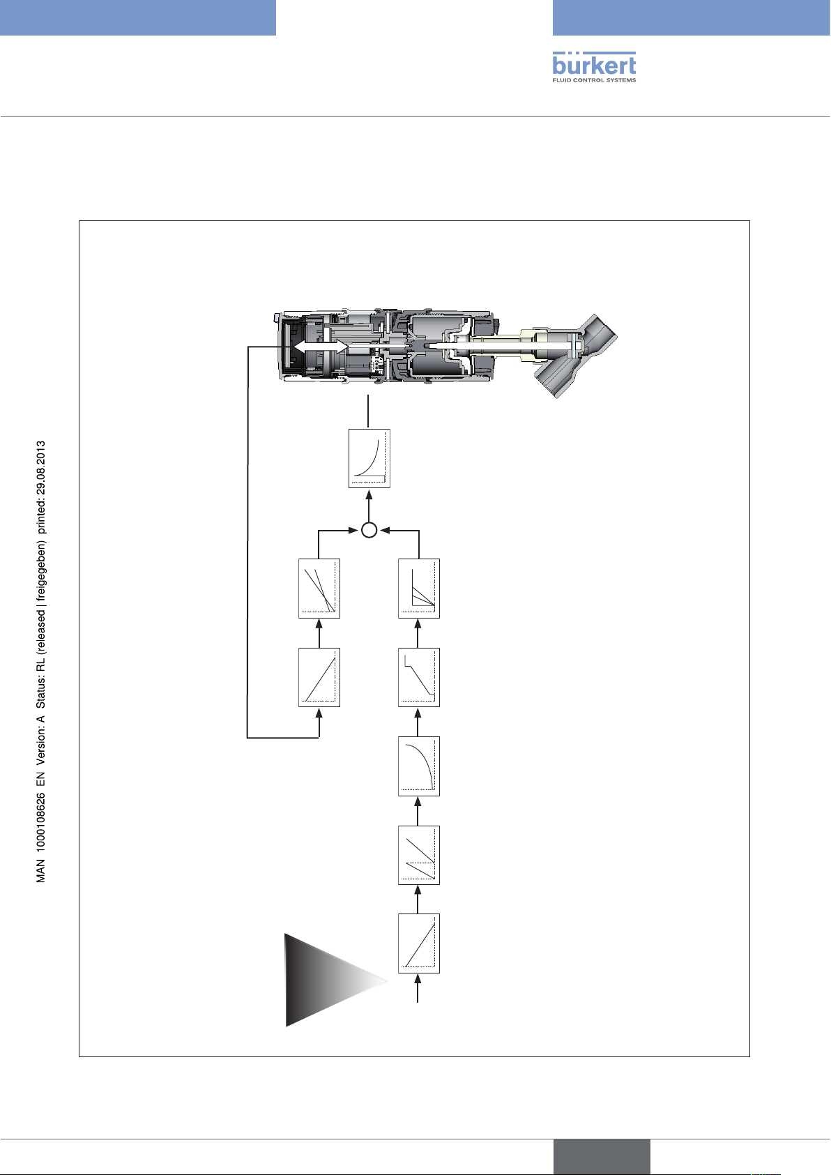
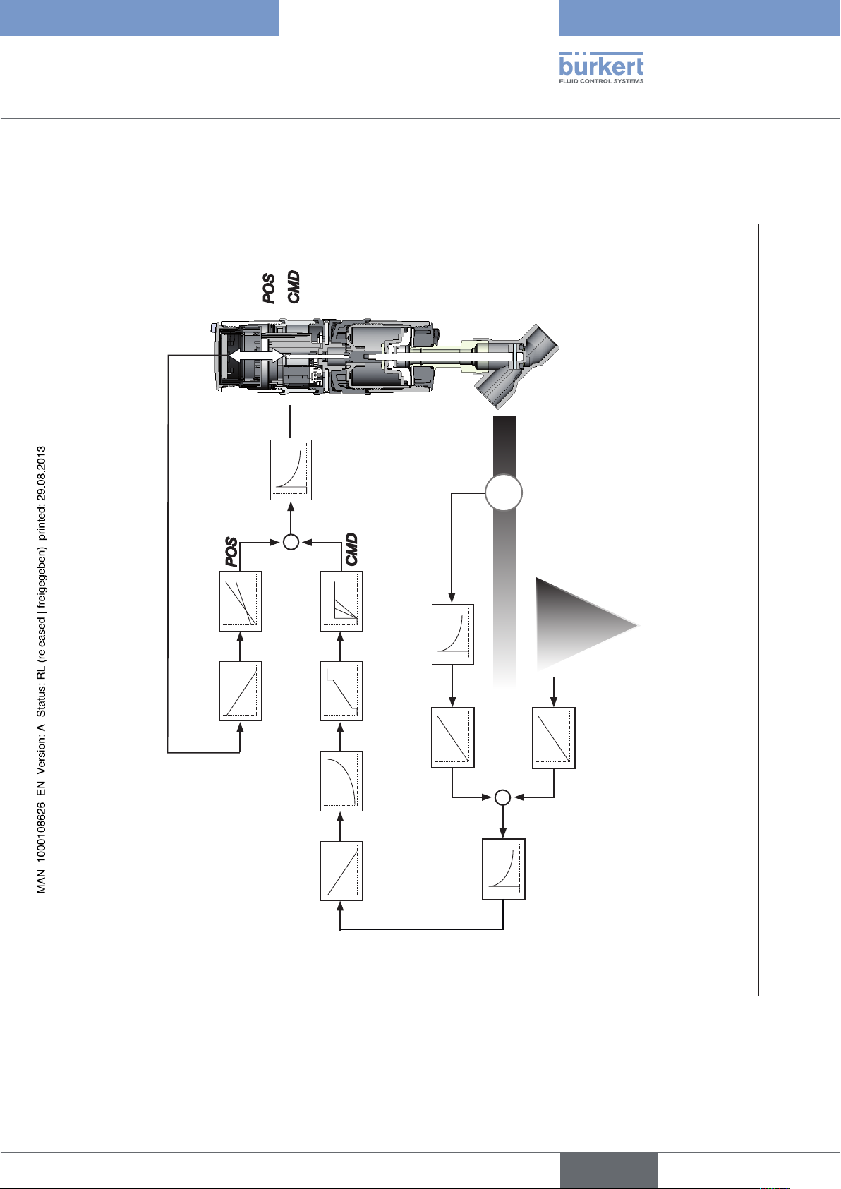
7.1. Schematic representation of the positioner
Type 8692
POS
CMD
TEMP
INPUT
POS
DIR.ACT X.LIMIT
X.CONTROL
DBND
CMD
4 … 20 mA
0 … 20 mA
0 … 10 V
Figure 5: Schematic representation of position control
0 … 5 V
DIR.CMD SPLTRNG CHARACT CUTOFF X.TIME
INP
21
english
Type 8692, 8693
Description of system
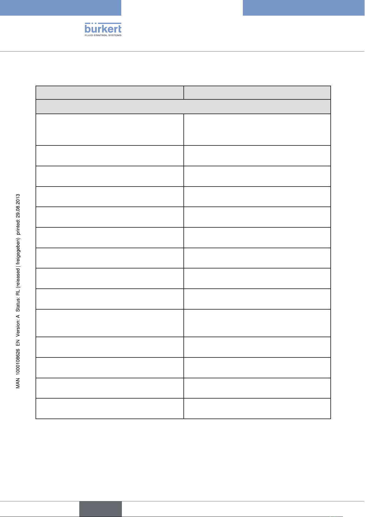
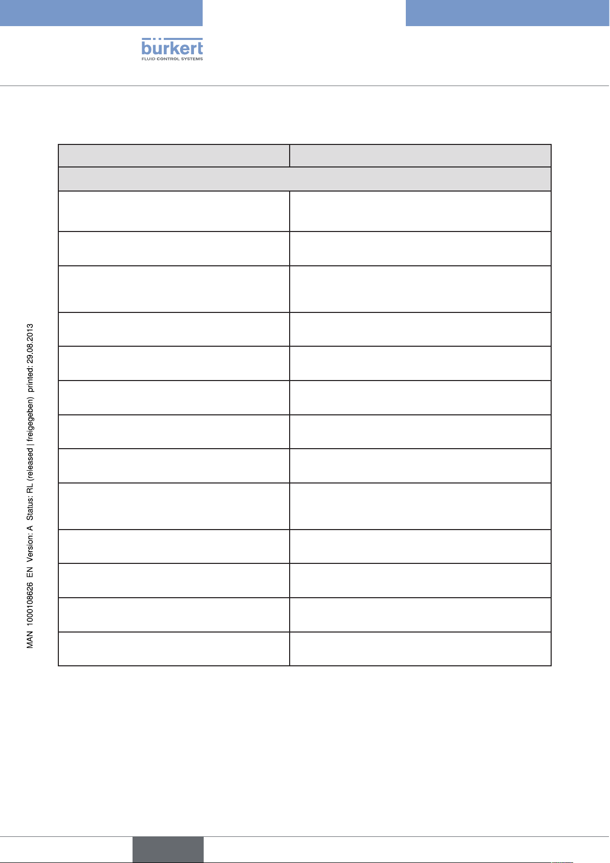
7.2. Properties of the position controller software
Additional function Action
Position controller with additional function
Sealing function
CUTOFF
Stroke limit
X.LIMIT
Signal range splitting
SPLTRNG
Correction line to adjust the operating characteristic
CHARACT
Insensitivity range
X.CONTROL
Effective direction of the controller nominal value
DIR.CMD
Safety position
SAFEPOS
Limit of the control speed
X.TIME
Effective direction of the actuator
DIR.ACT
Signal level error detection
Valve closes tight outside the control range. Specification of the value (in %), from which the actuator is
completely deaerated (when 0%) or aerated (when
100%).
Mechanical valve piston movement only within a
defined stroke range
Splitting of the standard signal range to two or more
positioners
The operating characteristic can be linearized
The position controller is initially actuated from a
control difference to be defined
Reversal of the effective direction of the nominal value
Definition of the safety position
Input of the opening and closing time for the entire
stroke
Adjustment of the effective direction between aeration
state of the actuator and the actual position
Check the input signals for sensor break.
22
SIG.ERROR
Binary input
BINARY. IN
Analogue feedback (option)
OUTPUT
2 binary outputs (option)
OUTPUT
User calibration
CAL.USER
Table 2: Functions position controller
Warning output on the display and start up of the
safety position (if selected)
Switch over AUTOMATIC-MANUAL or
Start up of the safety position
Status signal set-point or actual value
Output of two selectable binary values.
Change to the factory calibration of the signal input
english
Type 8692, 8693
Description of system,
Hierarchical control concept for easy control on the following levels
Process control On this level switch between AUTOMATIC and
MANUAL mode.
Configuration and parameterisation On this level specify certain basic functions during
start-up and, if required, configure additional functions
Table 3: Position controller — hierarchical control concept
english
23
Type 8692, 8693
Description of system
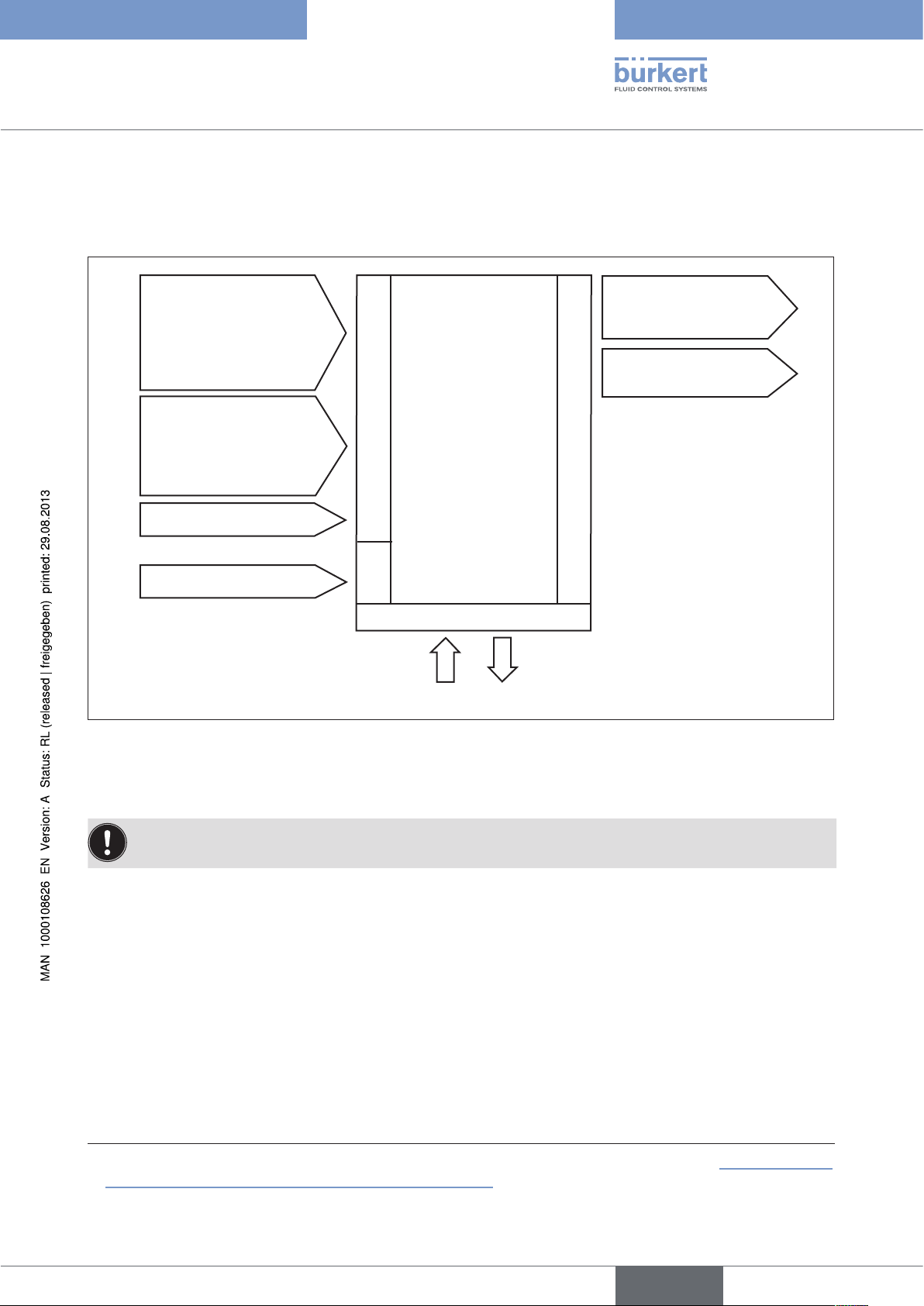
8. TYPE 8693
POSITIONER WITH PROCESS CONTROLLER
If the positioner is operated with process controller Type 8693, the aforementioned position control becomes the
subordinate auxiliary control circuit; this results in a cascade control. The process controller in the main control
circuit of the positioner has a PID function. The process set-point value (SP) is specified as set-point value and
compared with the actual value (PV) of the process variable to be controlled. The position measuring system records
the current position (POS) of the pneumatic actuator. The position controller compares this actual position value
with the set-point value (CMD), which is determined by the process controller. In case of a control deviation (Xd1),
a pulse-width modulated voltage signal is sent to the control system as a manipulated variable. If there is a positive
control difference in single-acting actuators, the air inlet valve is controlled via output B1. If the control difference is
negative, the bleed valve is controlled via output E1. In this way the position of the actuator is changed until control
difference is 0. Z2 represents a disturbance variable.
SP
+
Process set-point
value
CMD
+
Xd2
Process controller
Xd1
—
Position
controller
Position control circuit
CMD
Position
control
circuit
B1
E1
Control system
solenoid valves
POS
Valve
opening
Z1
P
K
Continuous
valve
Position measuring
Z2
Process
Valve
opening
Process variable
24
PV
Transmitter
Figure 6: Signal flow plan of process controller
english
Type 8692, 8693
Description of system,
8.1. Schematic representation of the process control
POS
CMDPVSP
TEMP
POS
—
DIR.ACT X.LIMIT
X.CONTROL
DBDx
+
CMD
PV SCALE
DIR.CMD CHARACT CUTOFF X.TIME
FILTER
PV
PV
Q
4 … 20 mA
0 … 20 mA
0 … 10 V
0 … 5 V
SP SCALE
SP
—
+
SP
P.CONTROL
PARAMETER
SETUP
Figure 7: Schematic representation of process control
25
english
Type 8692, 8693
Description of system
8.2. Functions of the process controller software
Additional function Action
Position controller with additional function
Sealing function
CUTOFF
Stroke limit
X.LIMIT
Correction line to adjust the operating
characteristic
CHARACT
Insensitivity range
X.CONTROL
Effective direction of the controller nominal value
DIR.CMD
Safety position
SAFEPOS
Limit of the control speed
X.TIME
Effective direction of the actuator
DIR.ACT
Signal level error detection
Valve closes tight outside the control range. Specification
of the value (in %), from which the actuator is completely
deaerated (when 0%) or aerated (when 100%).
Mechanical valve piston movement only within a defined
stroke range
The operating characteristic can be linearized
The position controller is initially actuated from a control
difference to be defined
Reversal of the effective direction of the nominal value
Definition of the safety position
Input of the opening and closing time for the entire stroke
Adjustment of the effective direction between aeration
state of the actuator and the actual position
Check the input signals for sensor break.
26
SIG.ERROR
Binary input
BINARY. IN
Analogue feedback (option)
OUTPUT
2 binary outputs (option)
OUTPUT
User calibration
CAL.USER
Table 4: Functions position controller
Warning output on the display and start up of the safety
position (if selected)
Switch over AUTOMATIC-MANUAL or
Start up of the safety position
Status signal set-point or actual value
Output of two selectable binary values.
Change to the factory calibration of the signal input
english
Type 8692, 8693
Description of system,
Additional function Action
Process controller with additional function
Controller structure
PID
P.CONTROL
Adjustable parameters
P.CONTROL — PARAMETER
Scalable inputs
P.CONTROL — SETUP
Selection of the nominal value specification
P.CONTROL — SETUP — SP INPUT
Process characteristic linearization
P.Q‘LIN
Process controller optimization
P.TUNE
Table 5: Functions process controller
Proportional coefficient, reset time, hold-back time and
operating point
Position of the decimal points, lower and upper scale
values of the actual process value and the process setpoint value
Set-point value specification either via standard signal
input or via keys
Function for automatic linearization of the process
characteristics
Function for automatic optimization of the process controller parameters
Hierarchical control concept for easy control on the following levels
Process control On this level switch between AUTOMATIC and MANUAL
mode.
Configuration and parameterization On this level specify certain basic functions during start-
up and, if required, configure additional functions
Table 6: Process controller — hierarchical control concept
english
27
Type 8692, 8693
Description of system
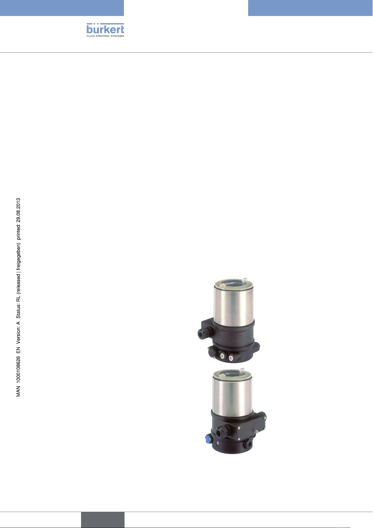
9. INTERFACES OF THE POSITIONER FOR THE
MULTIPOLE MODEL
Inputs for position or
process set-point value
4 – 20 mA
0 – 20 mA
0 – 10 V
0 – 5 V
Input for process
actual value
4 – 20 mA
Frequency
Pt 100
Binary input
24 V DC
Figure 8: Interfaces for the multipole model
Positioner
(Multipole model)
Inputs
Supply
Operation
2 binary outputs
Proximity switch 1
Analogue
position feedback
Outputs
28
The positioners Type 8692 and Type 8693 are 3-wire devices, i.e. the power (24 V DC) is supplied separately
from the set-point value signal.
english
Type 8692, 8693
Description of system,
10. INTERFACES OF THE POSITIONER FOR THE
MODELS WITH CABLE GLAND
Inputs for position or
process set-point value
4 – 20 mA
0 – 20 mA
0 – 10 V
0 – 5 V
Input for process actual
1)
value
4 – 20 mA
Frequency
Inputs
Pt 100
Binary input
24 V DC
Figure 9: Interfaces for the model with cable gland
Supply
Positioner
(Cable gland)
Operation
2 binary outputs
(as an alternative to input
for process actual value)
Analogue position
feedback
Outputs
1)
The positioners Type 8692 and Type 8693 are 3-wire devices, i.e. the power (24 V DC) is supplied separately
from the set-point value signal.
1) Type 8693: The switch can be used to supply power to a connected sensor (description see “18.5.1 Terminal
assignment when selecting the process actual value input”)
english
29
Type 8692, 8693
Description of system
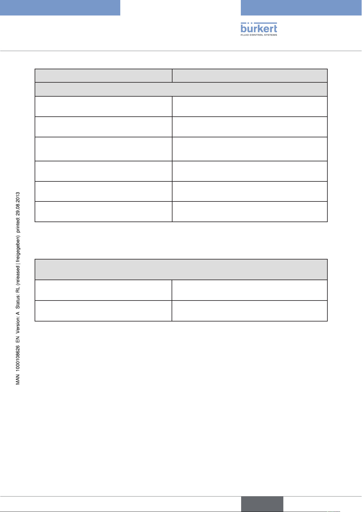
11. TECHNICAL DATA
11.1. Safety positions after failure of the electrical or
pneumatic auxiliary power
Safety positions after failure of the auxiliary
Actuator system Designation
electrical pneumatic
power
pilot-controlled
control system:
up
down
up
down
up
down
single-acting
control function A
single-acting
control function B
double-acting
control function I
down
up
down / up
(depending on the con-
nection of the control
cables)
down
direct-acting
control system:
not defined
pilot-controlled
control system:
up
direct-acting
control system:
not defined
not defined
30
Table 7: Safety positions
english
Loading…
Компактный датчик фактического положения типа 8692 разработан для интегрированной установки на пневматические приводы серий регулирующих прямоточных клапанов типа 23XX/2103 и специально для технологических условий гигиенических процессов. Подвод воздуха системы управления в привод происходит интегрированно, без использования внешних гибких трубопроводов. Легкое обслуживание и широкий выбор дополнительных программных функций осуществляются на большом графическом дисплее с фоновой подсветкой и через сенсорную клавиатуру или интерфейс ПК. Датчик фактического положения определяет положение клапана, не подвергаясь износу, через бесконтактный аналоговый сенсор. Благодаря наличию диагностических функций можно контролировать условия эксплуатации регулирующего клапана. Диагностические сообщения о клапане через сигналы о состоянии направляются согласно NE107 (NAMUR) и сохраняются в форме хронологических записей. Корпус из материалов, устойчивых к воздействию химии, легко подвергается чистке и предлагает зарекомендовавшую себя на практике защиту оболочки для эксплуатации в гигиеническом технологическом оборудовании продовольственной и фармацевтической отраслей. В комбинации с приводами Bürkert серии ELEMENT пневматическая система управления позволяет осуществлять вентиляцию полости установки пружины, препятствуя при этом загрязнению пневматических камер исполнительного механизма со стороны окружающей среды.
- Компактная и надежная конструкция из высокосортной стали
- Простейший ввод в эксплуатацию благодаря автоматической функции X-Tune
- Бесконтактный датчик перемещения
- Интегрированный подвод воздуха системы управления и вентиляция полости установки пружины
- Коммуникация Profibus DPV1 или DeviceNet (опция)
-
Прайс-лист на продукцию
-
8630, 8635, 8692, 8696, 8791. Техническое описание (eng).
-
Каталог продукции Burkert
-
ЦЕНЫ
Цены можно обсуждать, Burkert всегда старается найти компромисс со своими клиентами. Постоянным клиентам предоставляются скидки.
-
СЕРТИФИКАТЫ
Компания очень щепетильно относится к вопросам сертификации продукции, которую производит. Поэтому имеет все необходимые сертификаты на поставляемую продукцию.
-
КУЛЬТУРА
Burkert создает культуру, которая позволяет внедрить инновации, коммуникации и служит основой для гибких и открытых сотрудников компании.
-
Электромагнитные клапаны
0223, 0255, 0256, 0285 и др.
-
Электромагнитные клапаны сервоуправляемые
2W-A, RSPS, YSA и др.
-
Наклонные отсечные и регулирующие клапаны
серии 2060, 3320 и др.
-
Прямые отсечные и регулирующие клапаны
серии 2006, 2106 и др.
-
Мембранные клапаны
2030, 2031, 2063, 2103 и др.
-
Многопроходные и 3-ходовые клапаны
серии Robolux 2036 и др.
-
Клапаны для гигиенических применений
серии 2064, 2105 и др.
-
Шаровые краны, дисковые затворы
2657, 2658, 8804, 8805 и др.
-
Пневматика и процессные интерфейсы
0450, 5411, 5413, 5420 и др.
-
Аналитические датчики
8200, 8202, 8203, 8220 и др.
-
Преобразователи давления
8010, 8011, 8012 и др.
-
Мембранные и микродозирующие насосы
7604, 7615 и др.
-
Расходомеры жидкостей
8010, 8011, 8012, 8020 и др.
-
Расходомеры газа
8006, 8626, 8700, 8701 и др.
-
Уровнемеры
8136, 8129 и др.
-
Датчики и реле давления
8316, 8763 и др.
-
Датчики и реле температуры
TST001, 8400 и др.
-
Позиционеры, контроллеры, блоки управления
1067, 8630, 8695, 8692 и др.
-
Сервоприводы
серии 2052, 3005 и др.
-
Фильтрационные модули
C-CUT, T-CUT и др.
Обратитесь к нам или региональному дилеру для получения более подробной информации о сертификатах, характеристиках, отзывах, стоимости, наличии на складе и сроках поставки оборудования Burkert.
Мы гарантируем ответ в течение 8 рабочих часов
адрес для заявок: btk@nt-rt.ru
-
029 — Громова Марина
Здравствуйте! Я могу вам чем-то помочь?
Оператор набирает сообщение
Здравствуйте! Какая продукция Вас интересует?
Задайте вопрос прямо сейчас:
|
Цифровой электропневматический позиционер Burkert 8692 предназначен для установки на регулирующие пневмоклапаны Burkert серии 2300/2103 и 2702/2712. Позиционер изготовлен из нержавеющей стали и полисульфона, что позволяет использовать его в CIP-процессах. Позиционер оснащен ЖК-дисплеем с подсветкой и 4 клавишами управления. Доступны исполнения с коммуникацией по PROFIBUS DP-V1, DeviceNet, EtherNet/IP, PROFINET, Modbus TCP или büS (Bürkert System Bus). Документация8692 — Цифровой позиционер |
- Аналогичные товары
Вся информация на сайте о товарах и ценах носит справочный характер и не является публичной офертой. Производитель оставляет за собой право изменять характеристики товара, его внешний вид и комплектность без предварительного уведомления продавца
Цифровой электропневматический позиционер Burkert 8692 разработан специально для регулирующих пневмоклапанов Burkert 23XX/2103. Позиционер изготовлен из нержавеющей стали и полисульфона, что позволяет использовать его в CIP-процессах.
Позиционер оснащен ЖК-дисплеем с подсветкой и 4 клавишами управления.
Технические данные
производитель
Burkert
Если вы хотите купить цифровой электропневматический позиционер Burkert 8692 , вы можете:
Ещё из раздела Позиционеры для регулирующих клапанов Burkert
Электропневматический позиционер/ПИД-регулятор Burkert 1067 применяется совместно с регулирующими пневмоклапанами Burkert . Позиционер 1067 может устанавливаться как на регулирующие клапаны Burkert серии 2702/2712, так и на линейные пневмоприводы и …
Электропневматический позиционер/ПИД-регулятор Burkert 8630 Top Control применяется для регулирующих пневмоклапанов. Позиционер 8630 Top Control устанавливается на регулирующие клапаны Burkert серии 2702/2712. Технические данные Инструкция по …
Электропневматический позиционер/ПИД-регулятор Burkert 8635 SideControl применяется совместно с регулирующими пневмоклапанами Burkert . Позиционер 8635 может устанавливаться как на регулирующие клапаны Burkert серии 2702/2712, так и на линейные …
Цифровой электропневматический позиционер Burkert 8696 разработан специально для регулирующих пневмоклапанов Burkert 23XX/2103 с приводом Ø 50 мм. Позиционер 8696 изготовлен из нержавеющей стали и полисульфона, что позволяет использовать его в …
Электропневматический позиционер (регулятор положения) Burkert 8792 используется для регулирующих пневмоклапанов как простого, так и двойного действия. Позиционер 8792 является усовершенствованной моделью 1067. Позиционер 8792 выгодно отличается от …
Электропневматический позиционер (ПИД-регулятор) Burkert 8793 используется для регулирующих пневмоклапанов как простого, так и двойного действия. Позиционер 8793 является усовершенствованной моделью 1067. Отличие от позиционера 8792 заключается в …
Почему вы выбрали именно этот товар?
Для каких целей планируете использовать?
Устраивает ли вас соотношение цены и качества?
Не терпим нечестные отзывы, а также:
Мат, ругательства, оскорбления и угрозы
Контактную информацию, рекламу и прочее, не относящиеся к теме
Обсуждение цены товара и ее изменение
Отзывы по обслуживанию и сервису следует оставлять через раздел Гарантийное обслуживание, там они будут рассмотрены в обязательном порядке