
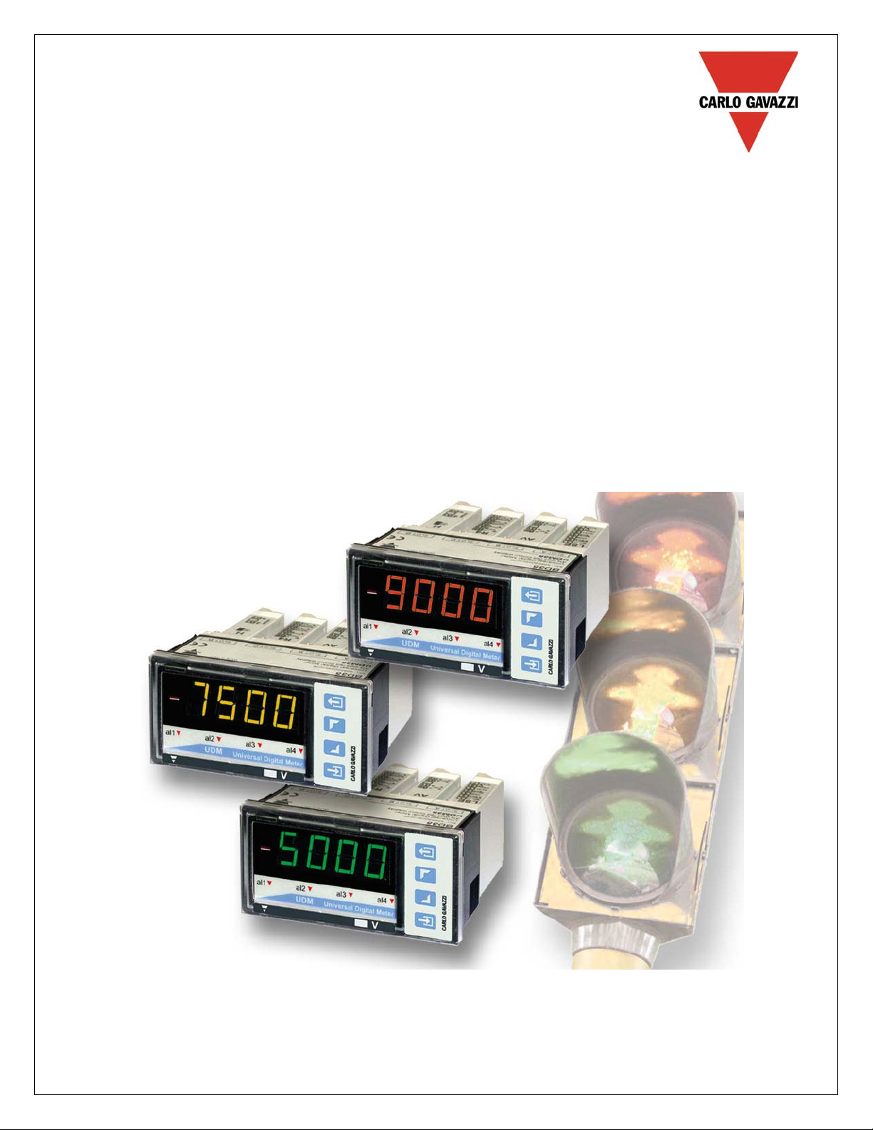
CARLO GAVAZZI
Automation Components
UDM 35/40 Digital Panel Meter
Programming Guide
UDM 35/40 PANEL METER USER MANUAL
Index
Description 2
Programming Fundamentals 3
Access to Programming Mode/Password Protection 4
Programming 5—18
Inputs 5-6
Temperature Compensation 6-7
Display Configuration 7
Scaling the Inputs 8
Decimal Point Position 9
Display Span Configuration 9
Linearization 11-12
Alarm Set Point Configuration 12-16
Digital Filtering 16-17
Analog Output/Retransmission of Display Value 17-18
Serial Port Output 18
Fahrenheit/Celsius Conversion 19
External Command Function 20
UDMSoft User Guide 21
1

UDM 35/40 PANEL METER USER MANUAL
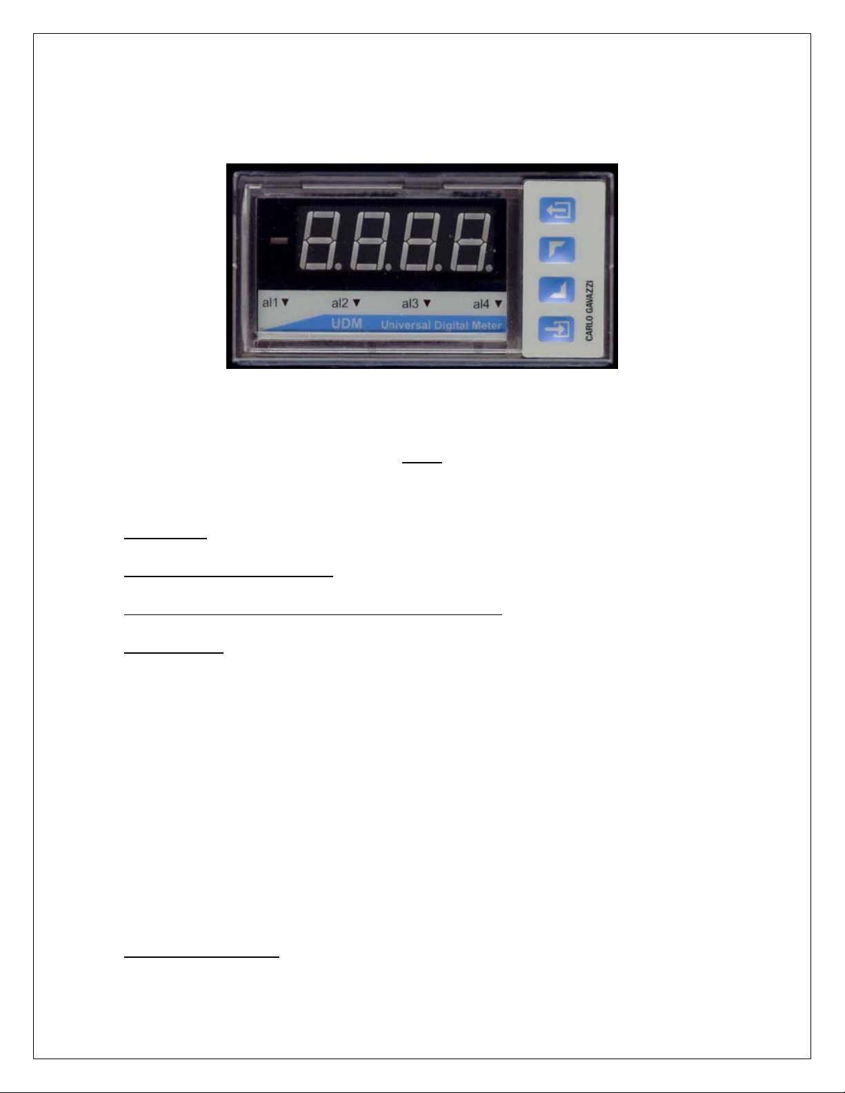
UDM Description
The UDM 35/40 series is a universal Digital Panel Meter that has been
developed to meet the most advanced application requirements. The UDM 35
offers:
• Quick assembly and maintenance using plug & play modules
• Quick & easy parameter programming and parameter cloning to
other UDMs by means of UDMSoft or PC HyperTerminal
• Powerful variable control by means of up to four (4) alarm outputs
• Alarms can be up-down functions with automatic reset, up-down
with manual reset, and down alarm with disable function at powerup.
The UDM 40 offers the same features as the UDM 35, with the following
additional benefits:
• Display color adaptable to Green, Red and Amber
• Management of non-linear signals using the available 16-point
linearization capability
• “Alarm status at a glance” using a sequence of display colors that
can be programmed by the user
2
UDM 35/40 PANEL METER USER MANUAL
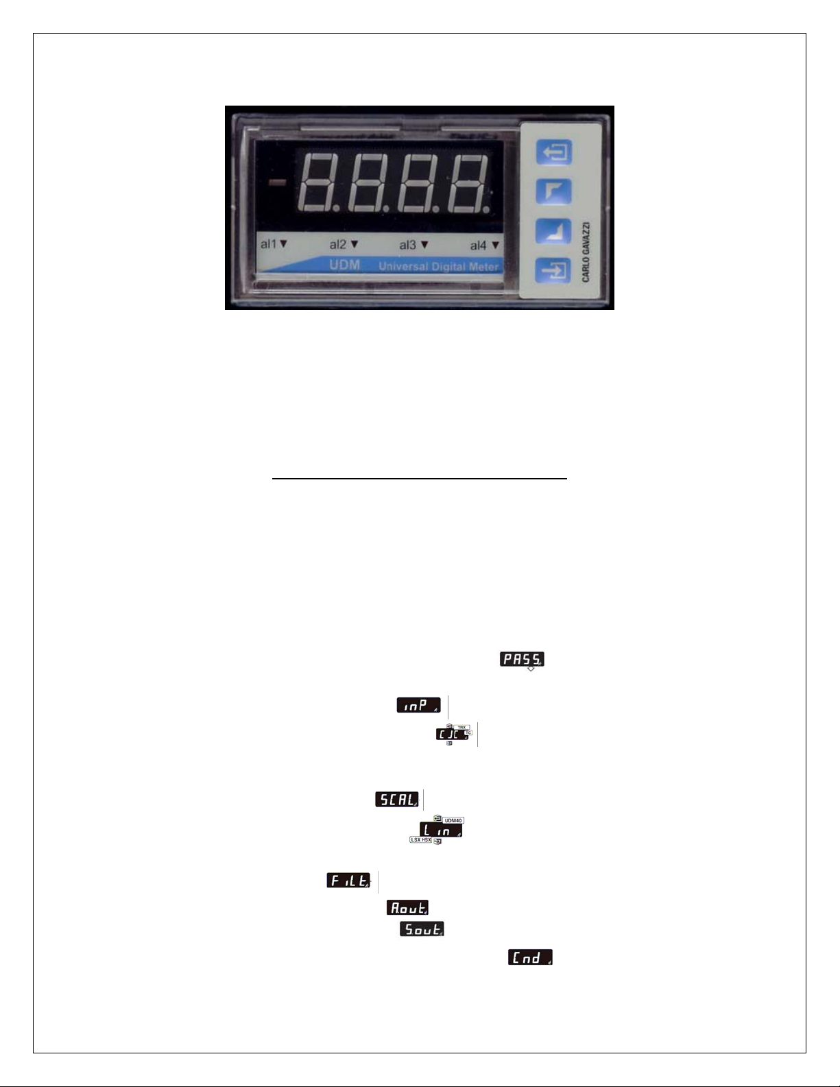
UDM 35/40 Programming Fundamentals
There are no jumpers to consider when programming the UDM 35/40. The
programming mode allows the user to define all of the instrument’s parameters.
Shown below are a description and the UDMxx display symbol for each basic
parameter grouping:
• Password for access to programming
• Input Probe Selection / Signal Range (current, voltage,
temperature, resistance)
• Cold Junction Compensation
• Display Selection (diSP)
• Display Color (CoLr)
• Scaling of Input Value
• Input Signal Linearization
• Alarm Set-Point (SP1 – SP4)
• Digital Filtering
• Analog Output Scaling
• Serial Port Configuration
• External Command from Input Contact
3
UDM 35/40 PANEL METER USER MANUAL
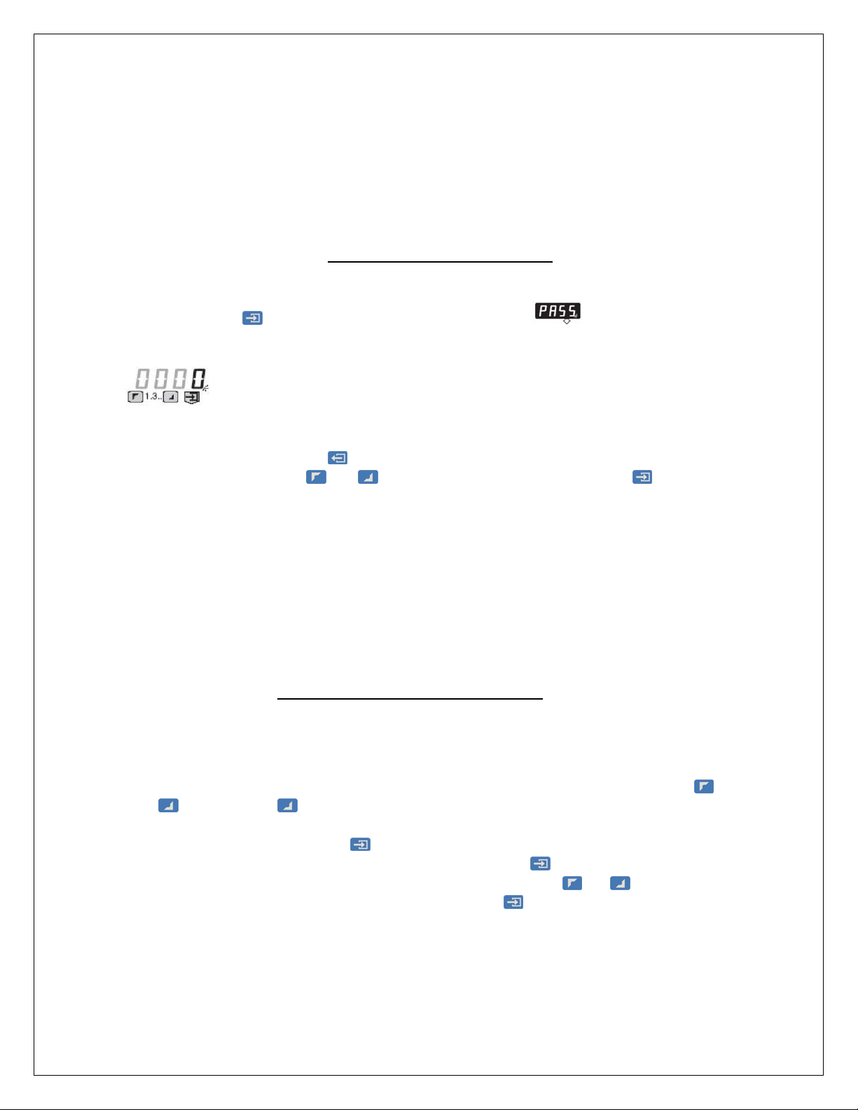
Access to Programming Mode
Press and hold for 2 seconds. Display will indicate (password).
Within 2 seconds, four zeros “0000” will be displayed as follow:
This is your prompt to enter your password. Each individual digit is selected from
left to right by toggling the key. Changing the value of each digit is
accomplished using the and arrows. When completed, press to
confirm this step. If the password you entered is not correct, you will not be
allowed access to program. Factory default password is set to “0000”.
Note: Choice of a password value is significant. Values from “0000” to “4999”
protect direct access to both set points and all other parameters. A password
value from “5000” to “9000” allow direct access to alarm set points only.
Negotiating the Programming Menu
After password is verified, you are in the Programming Mode. After
approximately 20 seconds, the unit will revert to RUN mode if no further entry is
made. Movement across the flow chart (see product carton instruction sheet for
BD35 and BD40) to a specific parameter heading is accomplished using the
and arrow keys. Pressing the UP key tabs from left-to-right across the flow
chart. Pressing the key tabs from right-to-left. Upon reaching the desired
parameter to configure, press
the first sub-parameter in this group. Each successive will scroll through the
remaining sub-parameters. To change a setting, press the
value of a sub-parameter is displayed, followed by to confirm the change and
advance to the next sub-parameter.
. The display will indicate the current setting for
or keys when a
4
UDM 35/40 PANEL METER USER MANUAL
Programming the Input Modules
Press and hold for 2 seconds. Display will indicate PASS (password). Within
2 seconds, four zeros “0000” will be displayed. This is your prompt to enter your
password. If zero “0000” is your password, simply press to confirm. You
have approximately 20 seconds to begin programming before the unit reverts
back to run mode. (To enter a unique password, see Access to Programming
Mode, above.)
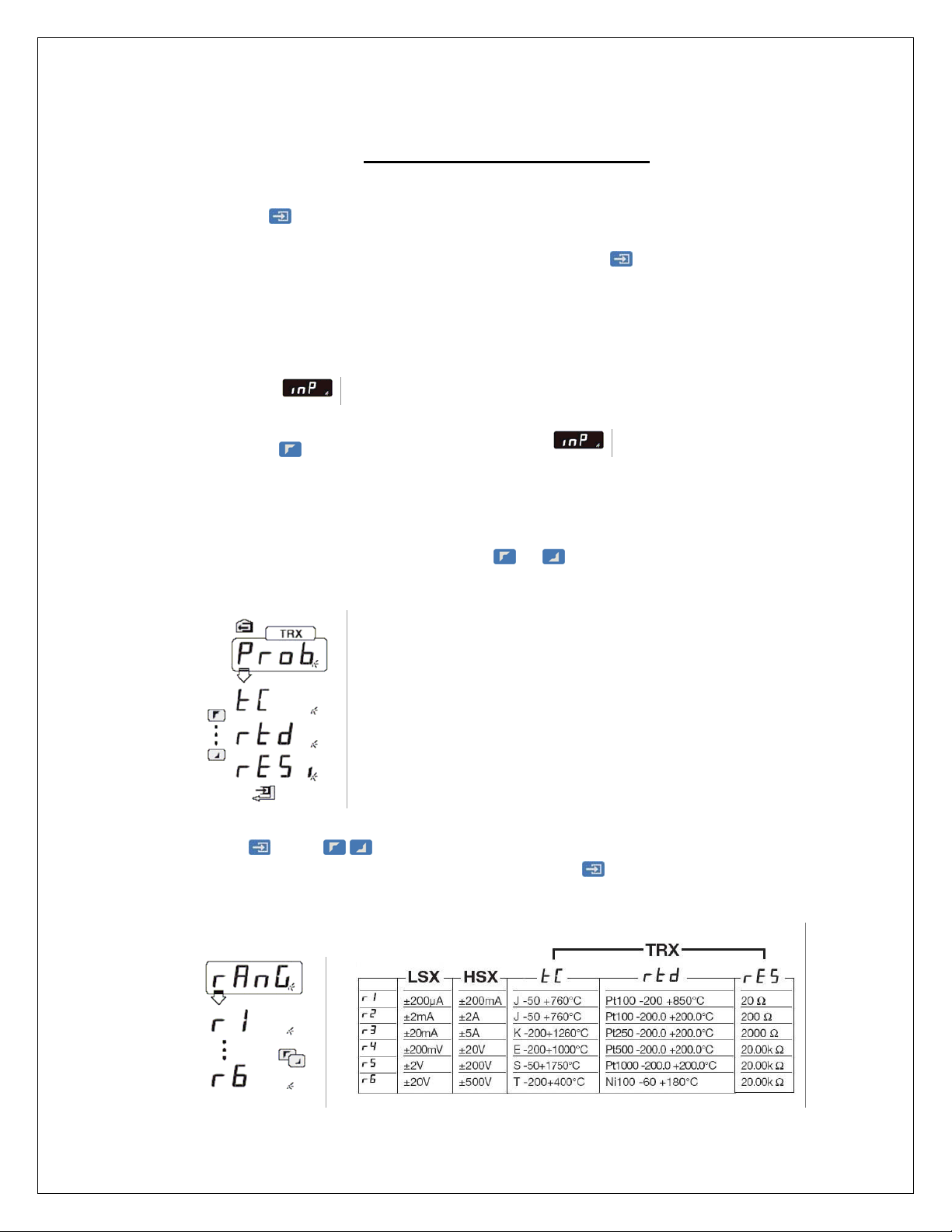
Input Selection
Press the key once to advance to Input
When the TRX module is installed, you must first indicate probe choice:
TRX input modules offer three Probe (Prob) choices: thermocouple* (tc),
RTD (rtd), plus resistive (rES). Use or keys to make selection.
Press . Use keys to select Range (r1, r2, r3, r4, r5, r6) according
to table below and on instruction sheet. Press
.
5
UDM 35/40 PANEL METER USER MANUAL
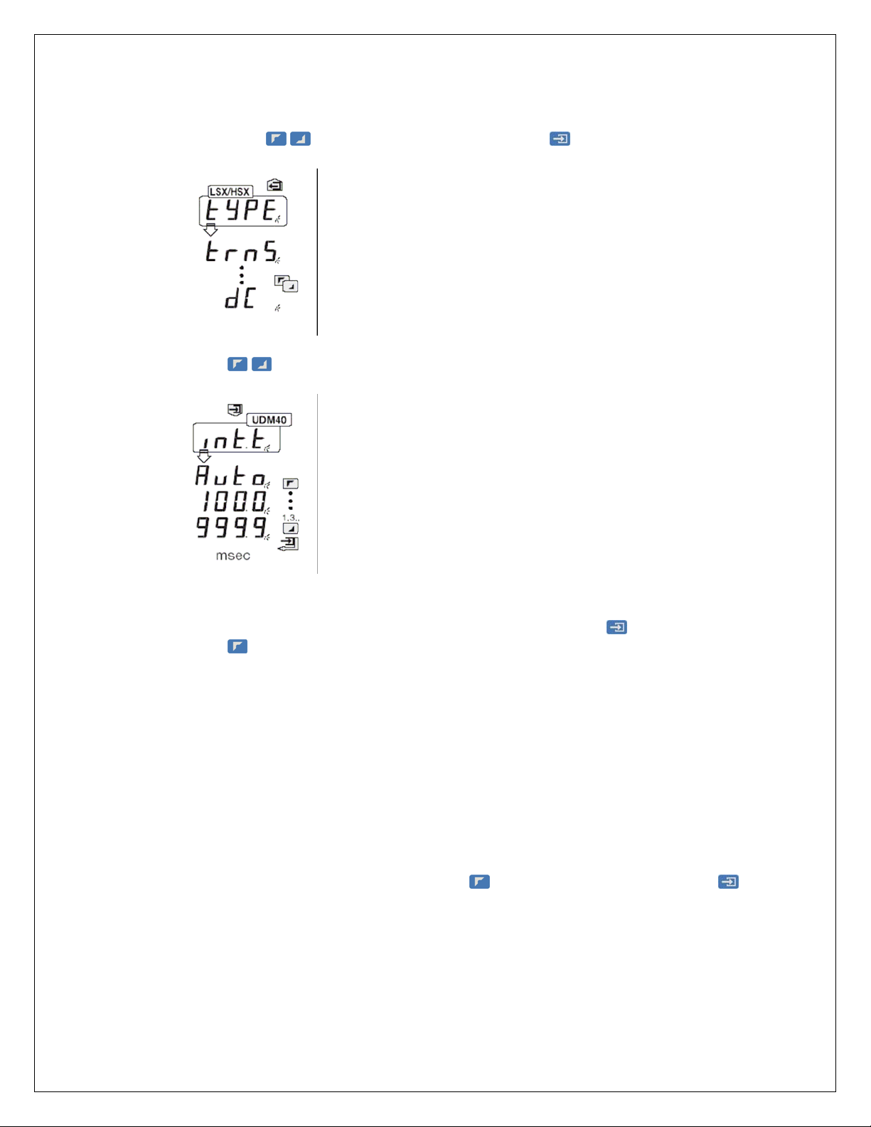
LSX and HSX input modules offer True RMS (trnS) or DC measurement
(dC). Use keys to make selection. Press .
Press keys to select Input signal integration time value (intt).
If all zeros “0000” is selected, “Auto” will be displayed and the value will be
automatically calculated from 100ms – 999.9 ms. Press to confirm.
Press to advance to next program step sequence.
Cold Junction Compensation (CJC) Temperature Compensation
Available only when TRX input module is installed.
TRX module with Thermocouple (tC) requires configuration of Cold
Junction Compensation (CJC). Press
to enter.
key to advance to CJC Then
6
Loading…
Bookreader Item Preview
162
Views
DOWNLOAD OPTIONS
Temporarily Unavailable
DAISY
For users with print-disabilities
Temporarily Unavailable
EPUB
Uploaded by
chris85
on
SIMILAR ITEMS (based on metadata)

ENGLISH
■
■ SAFETY PRECAUTIONS
Read carefully the instruction manual. If the instru-
ment is used in a manner not specified by the pro-
ducer, the protection provided by the instrument
may be impaired. Maintenance: make sure that the mount-
ing of the extractable modules and the relevant connec-
tions are correctly carried out in order to avoid any mal-
functioning or damage to the instrument. To keep the
instrument clean, use a slightly damp cloth; do not use any
abrasives or solvents. We recommend to disconnect the
instrument before cleaning it.
■
■ INSTRUCTIONS
: password. From 0 to 4999, the direct access to the set-
points and to the other parameters is completly protected. From
5000 to 9000 the direct access is allowed only to the alarm set-
points.
:
(only UDM40)
display colour. Selection of the basic
colour corresponding to the normal (non-alarm) status.
=
red, =
orange, =
green.
: selection of the function to be applied to A and B
inputs, whose result is displayed.
= stepped value of
channel A.
= 1/A.
= A-B.
= (A-B)/B*100.
=
A/B.
= B/(A+B)*100.
= Rotation direction: channel
B must replicate channel A with a phase difference.
DEUTSCH
■
■ SICHERHEITSMASSNAHMEN
Die Betriebsanleitung aufmerksam lesen. Sollte
das Gerät nicht gemäss der Herstellerangaben
verwendet werden, könnte der vom Gerät vorge-
sehene Schutz beeinträchtigt werden.
Wartung:
Sicherstellen, dass der Einbau der ausziehbaren Module
sowie die vorgesehenen Anschlüsse richtig ausgeführt
wurden, um schlechte Funktion oder Beschädigung des
Gerätes zu vermeiden. Das Gerät mit einem feuchten
Tuch reinigen; keine Scheuer- oder Lösemittel verwen-
den. Das Gerät vor der Reinigung ausschalten.
■
■ ANLEITUNGEN
:
Passwort. Von 0 bis 4999, direkter Zugang zu
Alarmschwellen und zu anderen Parametern komplett geschützt ist.
Von 5000 bis 9000, direkter Zugang nur zu den Alarmschwellen
möglich.
: (nur UDM40): Anzeigefarbe. Wahl der Grundfarbe
wenn kein Alarm. Wahl Anzeigefarbe:
= rot,
= orange,
= grün.
: Wahl der auf die Eingänge A und B anzuwenden-
den Funktion, deren Ergebnis angezeigt wird.
= gestuf-
ter Wert des Kanals A.
= 1/A.
= A-B.
= (A-
B)/B*100. =
A/B. =
B/(A+B)*100.
=
Drehrichtung: der Kanal B muss den Kanal A mit einer
FRANÇAIS
■
■ MESURES DE SECURITE
Lire attentivement le manuel de l’utilisateur. Si l’appa-
reil est utilisé dans des conditions différentes de celles
spécifiées par le fabricant, le niveau de protection prévu
par l’instrument peut être compromis. Entretien: S’assurer d’a-
voir effectué correctement le montage et câblage des modules
enfichables et des relatives connexions afin d’éviter tout mal-
fonctionnement ou endommagement de l’appareil. Pour main-
tenir propre l’instrument, utiliser un chiffon humide; ne pas uti-
liser d’abrasifs ou de solvants. Il faut déconnecter le dispositif
avant de procéder au nettoyage.
■
■ INSTRUCTIONS
:
mot de passe. De 0 à 4999, l’accès direct aux points
de consigne et aux autres paramètres est protégé. De 5000 à
9000, l’accès direct n’est permis qu’aux points de consigne.
: (seulement UDM40) couleur d’affichage. Sélection
de la couleur de base en condition de fonctionnement nor-
mal. Sélection de la couleur d’affichage
= rouge,
= orange,
= vert.
: sélection de la fonction à appliquer aux entrées A
et B dont le résultat est affiché.
= valeur pondérée du
canal A..
= 1/A.
= A-B.
= (A-B)/B*100.
=
A/B.
= B/(A+B)*100.
= Sens de la rotation : le canal
B doit répéter le canal A avec une différence de phase.
ESPAÑOL
■ NORMAS DE SEGURIDAD
Lea atentamente este manual de instrucciones. Si el
instrumento se usa de modo distinto al indicado por el
fabricante, la protección de seguridad ofrecida por el
instrumento podrá resultar dañada. Mantenimiento: asegúrese
de montar correctamente los módulos extraibles y los cables
correspondientes para evitar un mal funcionamiento y posibles
daños en el equipo. Para limpiar el equipo, utilizar siempre un
trapo ligeramente humedecido, nunca productos abrasivos o
disolventes. Se recomienda desconectar siempre el instrumen-
to antes de limpiarlo.
■
■ INSTRUCCIONES
:
password (clave). De 0 a 4999, el acceso directo a los
puntos de consigna y a los demás parámetros está totalmente
protegido. De 5000 a 9000, sólo está permitido el acceso a las
preselecciones de las alarmas.
: (sólo UDM40) color del display. Selección del
color principal predeterminado para el estado normal (con-
dición de no alarma).
= rojo,
= naranja,
= verde.
: Selección de la función de las entradas A y B, cuyo
resultado se visualiza.
= Frecuencímetro, Tacómetro de
la entrada del canal A.
= 1/A.
= A-B.
= (A-
B)/B*100.
= A/B.
= B/(A+B)*100.
= = Indica el
DANSK
■
■ SIKKERHEDSFORSKRIFTER
Læs brugervejledningen omhyggeligt.
Hvis instru-
mentet skal anvendes på en måde, der ikke er
beskrevet af producenten, kan instrumentets
beskyttelsesforanstaltninger være utilstrækkelige.
Vedligeholdelse: Kontrollér, at monteringen af udtrækn-
ingsmodulerne og de relevante tilslutninger foretages korrekt
for at undgå fejlfunktioner eller beskadigelse af instrumentet.
Brug en let fugtet klud til rengøring af instrumentet. Der må
ikke anvendes slibe- eller opløsningsmidler. Vi anbefaler, at
instrumentet frakobles før rengøring.
■
■ VEJLEDNING
:
adgangskode. Fra 0 til 4999 giver mulighed for
direkte adgang til de indstillede grænseværdier — øvrige
parametre er fuldt beskyttede. Fra 5000 til 9000 giver kun
mulighed for direkte adgang til de indstillede græn-
seværdier for alarm.
: (kun UDM40) displayfarve. Valg af grundfarve,
svarende til normal (ikke-alarm) status.
= rød,
= orange,
= grøn.
: Valg af den funktion, der skal anvendes ved ind-
gange A og B, hvis resultat derefter vises på skærmen.
= Værdi, som skaleres kanal A.
= 1/A.
= A-B.
=
(A-B)/B*100. =
A/B. =
B/(A+B)*100. =
!
!
!
!
!
ITALIANO
■
■ PRECAUZIONI DI SICUREZZA
Leggere attentamente il manuale di istruzioni. Qualora
l’apparecchio venisse adoperato in un modo non speci-
ficato dal costruttore, la protezione prevista dall’appa-
recchio potrebbe essere compromessa. Manutenzione:
Assicurarsi che il montaggio dei moduli estraibili e le connes-
sioni previste siano eseguiti correttamente al fine di evitare
qualsiasi malfunzionamento o danneggiamento dello strumen-
to. Per mantenere pulito lo strumento usare un panno inumidi-
to; non usare abrasivi o solventi. Si consiglia di scollegare lo
strumento prima di eseguire la pulizia.
■
■ ISTRUZIONI
: password. Da 0 a 4999, l’accesso diretto alle
soglie allarmi e agli altri parametri è totalmente protetto. Da
5000 a 9999, l’accesso diretto è consentito solo alle soglie
allarmi.
(solo UDM40) : colore display. Scelta del colore di
base in condizione di non allarme.
= rosso,
= arancione,
= verde.
: selezione della funzione da applicare agli ingressi
A e B, il cui risultato viene visualizzato.
= valore scala-
to del canale A.
= 1/A.
= A-B.
= (A-B)/B*100.
= A/B.
= B/(A+B)*100.
= Senso della rotazione: il
canale B deve replicare il canale A con una differenza di fase.
!
Firmware revision
Revisione del firmware
Revision Firmware
Révision du Firmware
Revisión de firmware
Firmware-revision
DK
E
F
D
I
UK
TF1
TF2
SX
AV
•
R1
R2
R4
R5
AV
•
H
L
•
Max 1 module in total
Massimo 1 modulo in totale
Maximal 1 Modul insgesamt
1 module complet au maximum
Máx. 1 módulo, en total
Maks. ét modul i alt
DK
E
F
D
I
UK
1
2
3
4
5
92mm -0.3/+0.8
3.62inch -0.01/+0.03
45mm -0.3/+0.6
1.78inch -0.01/+0.02
48mm
1.89inch
96mm 3.78inch
105mm
4.13inch
1
2
≤8mm
3,14inch
11mm
0.43inch
CARLO GAVAZZI
A u t o m a t i o n C o m p o n e n t s
Carlo Gavazzi Controls SpA,
Via Safforze, 8 — 32100
Belluno (Italy)
Tel. +39 0437 931000,
Fax +39 0437 931021
UDM35/40 TF
New password
Nuova password
Neues Passwort
Mot de passe nouveau
Nueva clave
Ny adgangskode
DK
E
F
D
I
UK
UDM40 TF IM cod. 8020844 040108
Tab 1
TF1/TF2
Hz
kHz
rpm
krpm
rph
krph
Display of set point value
Visualizzazione valore soglia
Anzeige Schwellenwert
Affichage de la valeur limite
Display del punto de consigna
Visning af forvalgt
grænseværdi
DK
E
F
D
I
UK
Minimum value
Valore minimo
Mindestwert
Valeur mini.
Valor Mínimo
Minimum værdi
DK
E
F
D
I
UK
Maximum value
Valore massimo
Höchstwert
Valeur maxi
Valor
Máximo Maximum
værdi
DK
E
F
D
I
UK
Reset of alarm latch
Reset ritenuta allarmi
Rücksetzen der Alarmselbsthaltung
Réinitialisation des alarmes à verrouillage
Puesta a cero de enclavamiento de alarma
Nulstilling af alarmselvhold
DK
E
F
D
I
UK
Tab 2
HOLD function
Funzione hold
Hold-
Funktion Fonction
HOLD Función
RETENCIÓN (HOLD)
HOLD-funktion
DK
E
F
D
I
UK
Key-pad disabling
Disabilitazione tastiera
Tastatur ausser Betrieb setzen
Désactivation du Clavier
Inhabilitación del
teclado
Deaktivering via tastatur
DK
E
F
D
I
UK
Reset of latch alarms
Reset allarmi con rite-
nuta
Rücksetzen der Alarme mit Selbsthaltung
Réinitialisation des alarmes avec verrou
Puesta a
cero de alarmas con enclavamiento
Nulstilling af
alarmer med selvhold
DK
E
F
D
I
UK

27.10.2013
•
Views
Share
Embed
Flag
UDM35/40 & USC User Manual — Carlo Gavazzi
UDM35/40 & USC User Manual — Carlo Gavazzi
SHOW MORE
SHOW LESS
ePAPER READ
DOWNLOAD ePAPER
- TAGS
-
display
-
displayed
-
input
-
programming
-
panel
-
manual
-
meter
-
toggle
-
output
-
analog
-
carlo
-
gavazzi
-
www.gavazzionline.com
gavazzionline.com
Transform your PDFs into Flipbooks and boost your revenue!
Leverage SEO-optimized Flipbooks, powerful backlinks, and multimedia content to professionally showcase your products and significantly increase your reach.
Start now
-
More Magazines
-
Recommendations
-
Info
CARLO GAVAZZI Automation Components UDM 35/<strong>40</strong> Digital Panel Meter Programming Guide
- Page 2 and 3: UDM 35/40 PANEL METER USER MANUAL I
- Page 4 and 5: UDM 35/40 PANEL METER USER MANUAL U
- Page 6 and 7: UDM 35/40 PANEL METER USER MANUAL P
- Page 8 and 9: UDM 35/40 PANEL METER USER MANUAL P
- Page 10 and 11: UDM 35/40 PANEL METER USER MANUAL D
- Page 12 and 13: UDM 35/40 PANEL METER USER MANUAL N
- Page 14 and 15: UDM 35/40 PANEL METER USER MANUAL N
- Page 16 and 17: UDM 35/40 PANEL METER USER MANUAL C
- Page 18 and 19: UDM 35/40 PANEL METER USER MANUAL P
- Page 20 and 21: UDM 35/40 PANEL METER USER MANUAL E
- Page 22: UDM 35/40 PANEL METER USER MANUAL L
Delete template?
Are you sure you want to delete your template?
Save as template ?
Title
Description
no error
products
- FREE
- adFREE
- WEBKiosk
- APPKiosk
- PROKiosk
Resources
- Blog
- API
- Help & Support
- Status
- tuxbrain.com
- ooomacros.org
- nubuntu.org
Company
- Contact us
- Careers
- Terms of service
- Privacy policy
- Cookie policy
- Cookie settings
- Imprint
Terms of service
Privacy policy
Cookie policy
Cookie settings
Imprint
Change language
Made with love in Switzerland
© 2025 Yumpu.com, all rights reserved