

HLP-NV Series


HLP-NV Series
I. Introduction 2
1. Checks upon Deliver y 3
2. Nameplate Desc ription of HLP-NV Series I nvert er 3
II. Safety Pre cautions 5
1. Before the Power-up 5
2. Dur ing the Power-up 6
3. Duri ng the Operat ion 6
4. Afte r the Power-off 7
III. Standards and Specicat ions 8
1. Particular Specications 8
2. General Specications 9
IV. Storage and Instal lation 11
1. Storage 11
2. Inst allat ion Site and Environment 11
3. Insta llation and Direction 11
V. Wiring 12
1. Main Circuit Wiring Schematic Diagram 12
2. Description of Terminal Block 13
3. Basic Connection Diagram 15
4. Switches 15
5. Precaut ions on Wiring 16
VI. Instruc tion of the LCP Digital Operator 19
1. Description of the LCP Digital Operator 19
2. Programming with LCP 19
VII. Parameter Overv iew 25
VIII. Parameter Descriptions 37
IX. Ma intena nce, Fault I nformat ion and Trouble shooting 90
1. Precautions about Inspection and Maint enance 90
2. Periodical In spection and Ma inten ance items 90
3. Fault Indication and Troubleshooting 91
3. Fault code descript ion and Analysis 92
HLP-NV Series

HLP-NV Series
IX. Appendices 96
Append ix 1: Mounti ng Dime nsions of HOLI P NV inverters 96
Append ix 2: Mount ing Dimensions of LCP Digit al oper ator 98
Append ix 3. Braking Resistor Disposition 98
Append ix 4. Simple Example of Appl iaction 99
Append ix 5:User’s feedback 106
HLP-NV Series
HLP-NV Series
I. Introduction
Than k you for purchas ing and using the gen eral- purp ose inver te r of
HLP-NV series of mu lti-functions and high performance.
Please read caref ully the operation m anual before putt ing the i nvert er to
use so as to correctly install and operate t he inverter, give f ull play to its
functions and ensure the safety. Please keep the operation manual handy
for future reference, maintenance, inspe ction and repai r.
Due to th e invert er of a k ind of ele ct rica l and elect ronic pr od uc t it
must be in sta lled, tested and adjust ed with parameters by specia lized
engineeri ng persons of motor s.
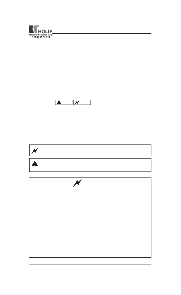
The ma rk s of
remind you of the s afet y and prevention caut ions d uring the handling,
inst allat ion, runn ing and inspection. Please follow t hese instructions to
make su re the safe use of the inver ter. In case of any doubt please contact
our local agent for consult ation. Our professional persons are w illing and
ready to serve you.
The manual is subject to change without notice.
Danger
Caution
and ot her sy mb ols in the ma nu al
Danger
Caution
indicates wrong use may k ill or injure people.
in di ca te s wro ng us e may damage the in ve rte r or
mechan ical system.
Danger
● Be sure to tur n off the input power supply before wiring.
● Do not touch any internal electrical circu it or component when the
charging lamp is sti ll on af ter t he AC power supply is disconnected,
which means the inver ter still has high voltage inside and it is very
dangerous.
● Do not check components and sig nals on the circuit boards dur ing
the operation.
● Do not dissemble or modify any internal con nect ing cord, wiring or
compone nt of the inverter by yourself.
● Be sure to make correct ground con nection of the earth terminal of
the inverter.
● Never remodel it or excha nge control boa rds and compon ent s by
yourself. It may expose you to an electrical shock or explosion, etc.
HLP-NV Series
— 1 —

HLP-NV Series
● Mo t or ov er lo ad prote cti on is inc lu ded in the defau lt set tin gs.
Parameter C01.90 Motor thermal protection is set to value ET R trip.
● Do not ma ke any vol ta ge-withstand ing test with any co mpone nt
ins ide the inverter. These sem i-cond uct or parts are subj ect to th e
damage of high voltage.
● Ne ve r connect th e AC m ain ci rc ui t powe r supply to th e out put
terminals U.V W of the inver ter.
● The main electric circuit boards of CMOS and IC of the inverter are
subject to the ef fect and d amage of st atic electricity. Don’t touch the
main ci rcuit boards.
● Installation, t esting and maintenance must be perfor med by qu alied
professional personnel.
● The inverter should be discarded as industrial waste. It is forbidden
to bur n it.
1. Checks upon Delivery
Th e inver ter has bee n str ictl y and well pa ck ed befo re ex-wo rk . In
co ns id er atio n of var io us fa ctor s d u rin g the tra nsp or tat io n spe ci al
attention should be paid to the followi ng points before the assembly and
installation. If there is anything abnor mal please notify the dealer or the
relevant people of our company.
● Check if the i nver ter has got any damage or defor mat ion during t he
transpor tation and handling.
● Check if the re is one piece of HLP-N V ser ies inverter and one copy of
the instruction manual ava ilable when unpacking it.
● Check the inform atio n on the n ameplate to see if the spe cif icat ions
meet your order (Operating voltage and KVA value).
● Check i f there is somethi ng wrong with the i nne r par ts, wir ing and
circuit board.
● Check if each te rm inal is tightly locked an d if there is a ny foreign
article inside the inver ter.
● Check if t he operator buttons are all rig ht.
● Check if t he option al components you ordered are conta ined.
● Check if t here is a ce rti cate of qu alication and a warr anty card.
Caution
— 2 —
HLP-NV Series
HLP-NV Series
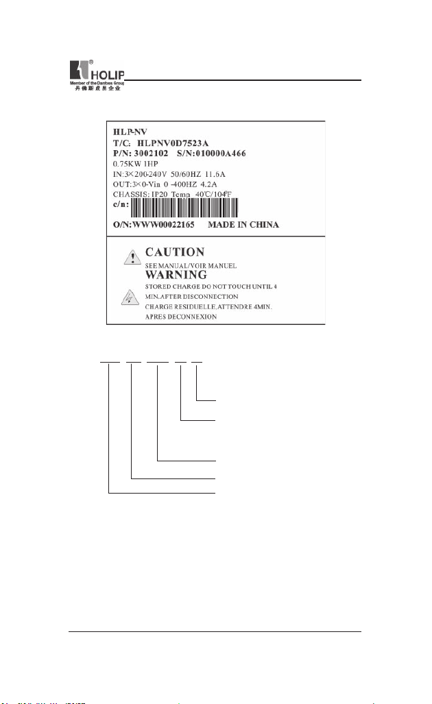
2. Nameplate Description of HLP-NV Series Inverter
Model HLP N V 0D75 23 A
Software Version: A
Voltage Rating: 21:1-Phase AC 220V
23:3-Phase AC 220V
43:3-Phase AC 380V
Inverter Capacity:0 D 75 mean s 0.75KW
Serial No: NV mean s NV ser ies
Trade Mark: HOLIP
HLP-NV Series
— 3 —
HLP-NV Series
II. Safety Precautions
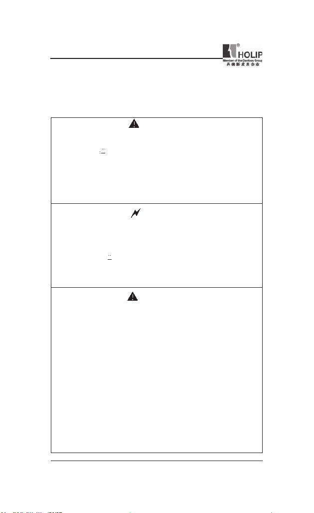
1. Before the Power-up
● Check to be sure t hat the voltage of the main circuit AC power supply
matches the input voltage of the i nverter.
● The symbol
correct ground con nection of the earth terminals of the motor and the
inverter for safety.
● No conta ctor should be inst alled betwee n the power supply and the
inverter to be used for star ting or stopping of the i nvert er. Otherwise
it will affect the serv ice life of the inverter.
● R(L), S,T( N) ter mi nals are powe r input ter minal s, never mixed
with U.V.W t erm inals. Be sure that the wiri ng of the main circuit is
cor rec t. Other wise it will cau se damage s of the inve rt er when the
power is appl ied to it.
● The terminal of
to li ne zero. Otherw ise it will easily cause the prote ction or er rors of
the inverter.
, repr esents grou nd te rmi na ls . Be su re to ma ke
Danger
must be grou nded separately and never connect ed
Caution
● Do not ca rr y t he front cover of the inver ter directly when handling.
It should be hand led with the base to prevent the fall-off of the f ront
cover and avoid the dr opp ing of the inve rt er, which may pos sibly
cause the injur ies to pe ople and the damages to the i nvert er.
● Mount the i nver ter on a met al or other nonc ombustible mater ial to
avoid the risk of re.
● Insta ll the inverter in a safe loc ation, avoid ing hig h tempe rat ure,
direct sunlight, hu mid ai r or water.
● Kee p the inv erte r fro m th e re a ch of chi ldr e n or pe r so ns not
concer ned.
● The in ve r te r can only be use d at the pla ce s acc redit ed by our
com pa ny. Any unau th or iz ed work ing envi ronment may have th e
risks of re, gas explosion, ele ctric shock and other incidents.
● Install a he at sink or other cooling device when inst alling more than
one inverter in the same enclosure so that t he temperature in side t he
enclosu re be kept below 40℃ to avoid overheat or the risk of re.
Caution
— 4 —
HLP-NV Series
HLP-NV Series
● Be su re to tu r n of f t h e po we r s up ply bef o re d i sse mbl i n g or
assembl ing the operation key panel a nd xing the front cover to avoid
bad cont act causing faults or non- display of the oper ator.
● Do not in stall the inverter in a space with explosive gas to avoid the
risk of explosion.
● If the i nvert er is used at or above 1000m above seal level, the cooli ng
efciency will be worse, so please run it by de-rating.
● Do not install any c ontactor and other comp onents of cap acit or or
var istor on the o utp ut side of the inverter. Other wise it will cau se
malfunctions and damages of components of the inverter.
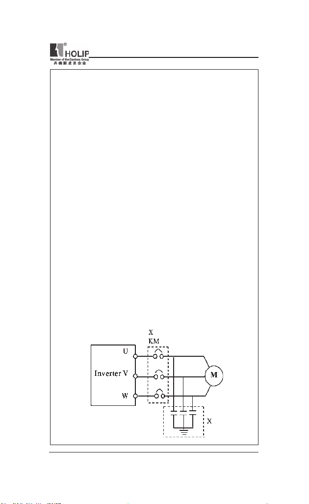
● Do not ins tall any switch co mp on en t like ai r cir cu it brea ke r or
cont actor at t he output of the i nverter. If any of such components
mu st be ins t al led beca use of t he req uir e me nts of pro ces s and
others, it must be ensu red that the inverte r has no out put when the
swit ch acts. In addit ion, it is forbidden to install any c apacitor for
improvement of power factor or any varist or agai nst thunder at t he
output. Othe rwise it will cause malfunctions, tr ipping protection a nd
damages of components of the inverter. Please remove them as shown
in the below diagr am.
● It wi ll affect the service life of the inverter if a contact is connected
to the front end of input of the inver ter t o cont rol its starts and st ops.
Generally it is re qu ir ed to cont rol it thr ou gh Con trol term inal s.
Special attention should be p aid t o its use in the case of frequent
star ts and stops.
● Pleas e use an indep ende nt powe r supply for the i nver ter. D o avoid
using the common power supply with an electrical welder and other
equipme nt wi th st ro ng di st urbance. Ot herwise it wi ll ca us e the
protection or even d amage of t he inver ter.
HLP-NV Series
— 5 —
HLP-NV Series
2. During the Power-up
● Do not plug the conne ctors of the inve rter du ri ng the power up to
avoid any surge i nto the main control board due to pluggi ng, which
might cause the damage of the inverter.
● Always have the protective cove r in place before the power up to
avoid electrical shock injur y.
Danger
3. During the Operation
● Never c onnect or discon nect the motor set while the inverter is in
run ning. O ther wise it will cause over-current trip and even bur n up
the mai n circu it of the inverter.
● Never rem ove th e fr ont cover of the inverter w hile the inve rt er is
powered up to avoid any inju ry of electric shock.
● Do not come close to the machine when the fault resta rt fu nction is
use d to avoid any thing unexp ect ed. The m otor may automa tic ally
resta rt af ter its stop.
● The f unction of STOP Swit ch is on ly valid af ter set ti ng, which is
different with the use of emergent stop switch. Please pay attention to
it when usi ng it.
Danger
● Do not touch the heat sink, braking resistor, or other heat elements.
Caution
These can become very hot.
● Be sure that the motor and m achine is withi n the applicable spe ed
ranges before sta rting operat ion because the inver ter is quite easy to
run f rom lower speed to higher sp eed.
● Do not check the sign al s on ci rcuit bo ar ds wh ile the inve rt er is
run ning to avoid danger.
● Be caref ul when changing the inver ter settings. The inverter has been
adju sted and set before ex-work . Do not a djust it wanton ly. Please
make proper adjustments according to the requ ired f unct ions.
● Do consider the vib ration, noise an d the speed limi t of the motor
bearings and the mechanical devices whe n the inverter is ru nni ng at
or above the f requency of 50Hz.
— 6 —
HLP-NV Series

HLP-NV Series
4. After the Power-off
● Touching t he electrical parts may be fatal — even afte r the equipment
ha s been disco nn ec ted f rom mains. Also ma ke su re th at ot he r
voltage input s have been disconnected, (li nkage of DC intermediate
circuit).
● Be aware that there may be high volt age on the DC lin k even when
the LEDs a re tu rned of f.
● Before touching any potentially live parts of the VLT Micro, wait at
least as follows:
200 — 240 V, 0.4 – 1.5 kW: wait at lea st 4 minutes.
380 — 480 V,0.75 – 2.2 kW: wait at least 4 minutes.
Shor ter time is allowed only if indicated on the nameplate for t he
specic unit.
HLP-NV Series
— 7 —
HLP-NV Series
III. Standards and Specications
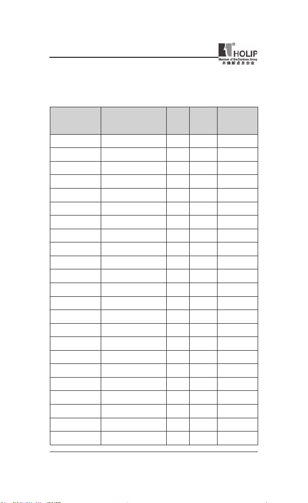
1. Particular Specications
Outp ut
Model Input Voltag e
HLPN V0D1821A 1×200-240V 50/60H z 0.18 1.2 0.18
HLPN V0D3721A 1×200-240V 50/6 0Hz 0.37 2.2 0.37
HLPN V0D7521A 1×200-240V 50/60 Hz 0.75 4.2 0.75
HLPN V01D521A 1×200-240V 50/60Hz 1.5 6.8 1.5
HLPN V02D221A 1×200-24 0V 50/60Hz 2.2 9.6 2.2
HLPN V0D2523A 3×200-240V 50/60Hz 0.25 1.5 0.25
HLPN V0D3723A 3×200-24 0V 50/60Hz 0.37 2.2 0.37
HLPN V0D7523A 3×200-24 0V 50/60Hz 0.75 4.2 0.75
HLPN V01D523A 3×200-240V 50 /60Hz 1.5 6.8 1.5
HLPN V02D223A 3×200 -240V 50/60Hz 2.2 9.6 2.2
HLPN V03D723A 3×200-24 0V 50/60Hz 3.7 15.2 3.7
HLPN V0D3743A 3×380-480V 50/60Hz 0. 37 1.2 0.37
HLPN V0D7543A 3×380-48 0V 50/60Hz 0.75 2.2 0.75
HLPN V01D543A 3×380-480V 50/60Hz 1.5 3.7 1.5
HLPN V02D243A 3×380- 480V 50/60Hz 2.2 5.3 2.2
HLPN V03D043A 3×380- 480V 50/60Hz 3.0 7.2 3.0
HLPN V04D043A 3×380- 480V 50/60H z 4.0 9.0 4.0
HLPN V05D543A 3×380-480V 50/60Hz 5.5 12 5.5
HLPN V07D543A 3×380- 480V 50/60Hz 7.5 15.5 7.5
HLPN V001143A 3×380-48 0V 50/60Hz 11 23.0 11
HLPN V001543A 3×380 -480V 50/60Hz 15 31.0 15
HLPN V18D543A 3×380-480V 50 /60Hz 18.5 37.0 18.5
HLPN V002243A 3×380-480V 50/60 Hz 22 43.0 22
Power
(KW)
Cur rent
(A)
Suitable
Motor
(KW)
— 8 —
HLP-NV Series
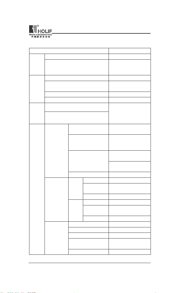
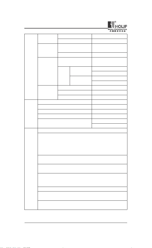
2. General Specications
Inverter Ser ies H LP-NV
Frequency 48~62HZ
Power
supply
Supply Voltage
Output voltage 0~100% of supply volt age
Output frequency
Motor
output
Over load 150% of rated cu rrent
Acc/De c time 0.05~3600s
Runn ing control
Control
Frequency sett ing
Number
Progr ammable
digital inputs
Control
terminals
Anology
inputs
Anology
output s
Voltage level
Logic Voltage level
Input resistance 4KΩ
Number 1;ter minal nos.: VI N
Voltage
Voltage level
Input resistance 10KΩ
Number 2; ter minal nos.: VI N,AIN
Cur rent
Cur rent ra nge
Input resistance 200 Ω
Number 1;Te rmi nal nos.: AO
Output Cur rent ra nge 0/4-20mA
Max.Load 500 Ω
Accuracy
Resolution 8bit
380~480V±10% for 380V
single/three phase
200~240V±10% for 220V
0-200H Z(V VC+),
0-400HZ(V/F)
LCP operate;
Multi input ter minals;
RS 485 ser ial
commu nication
5, term inal nos.: RUN
F/R,RST,JOG,EMS
0~24V DC (“PN P” OR
“NPN ”) ; Maximum
input: 28V DC
PNP: “0”<5VDC;
“1”>10VDC;
NPN: “0” >19VDC;
“1” <14VDC
0-10V DC ;
Maximum input 20V DC
0/4-20mA(scaleable);
Maximum input: 30mA
Max.er ror:0.5% of full
scale
HLP-NV Series
;
,
HLP-NV Series
— 9 —
HLP-NV Series
24V DC
RS 485
Control
terminals
Realy out pus
10V DC output
Enclosure IP20
Ambient temper ature -10℃~50
Max.relative hum idity 5%-95%
Surroundings
Vibration test 1.0g
Max.altitude above sea level
Electronic the rmal motor prot ection against overload.
Temperature monitoring of the heatsink ensures that the fre quency
converter tr ips if the temperatu re reaches 95 °C ± 5°C. An overload
temperatu re can not be reset until the temperature of t he heatsink
is below 70 °C ± 5°C (Guideline — these temperatures may vary for
different power si zes, enclosures etc.).
The frequency converter is protected against short-circuits on motor
terminals U, V, W.
The frequency converter is protected against ear th faults on motor
Protection
terminals U, V, W.
Functions
Monitor ing of the inter mediate circuit voltage ensures that t he
frequency conve rter trips if the intermediate circuit voltage is too low
or too hig h.
If a motor phase is missing, the frequency converter may tr ip.
If mains fault occurs, the frequency converter will ramp down to stop
and issues a war ning.
If a mains phase is missing, the frequency conver ter trips or issues a
warn ing (dependingon the load).
Terminal number EV
Max.load 200m A
Terminal number
Ground for RS485 COM
Terminal number
Resistive load
Max
load
Inductive load
Terminal number +10V
Output voltage 10.5±0.5V
Max.load 25mA
RS+(TX+,RX+),
RS- (T X-,RX-)
1,FA-FB(make),
FA-FC(break)
250V AC 2A
30V DC 2A
250V AC 0.2A
24V DC 0.1A
1000m
3000m(derati ng)
℃
— 10 —
HLP-NV Series

HLP-NV Series
IV. Storage and Installation
1. Storage
The invert er mu st be kept in its or iginal package box before in stallation.
Pay at tention to the followings when keeping it in storage if the inver ter
is not used for the time being:
● It must be stored in a d ry pla ce without rubbish or dust.
● The suitable temperat ure for storage is between -20℃ and +65℃.
● The relative humidity required is 0-95% without condensation.
● There is no corrosive gas or l iquid in t he storage ambience.
● It’s better to lay the inverter on a rack and keep it in a proper package.
● It is better not to store the inverter for long time. Long t ime storage of
the inver ter wil l lead to the deterioration of electrolytic capacity. If it
needs to b e stored for a long ti me make sure t o power it up one time
withi n a year and t he power-up ti me should be at least above ve hours.
When powered up t he voltage must be increased slowly with a voltage
regulator to the rated volt age value.
2. Installation Site and Environment
The inverter should be instal led at the following location:
● Ambient temper ature -5℃ to 40℃ with good ventilation.
● No water d rop and low moisture.
● Free from direct sunshine, h igh temperat ure and heavy dust fall.
● Free from corrosive gas or liquid.
● Less dust, oil gas and metallic pa rticles
● Free from vibration and easy for ser vice and inspection.
● Free from the interference of elect romag netic noise.
Attention : The ambient condit ions of the invert er will aff ec t its
service life.
3. Installation and Direction
● Th er e mu st be en ou g h sp ace lef t ar ound the inv er te r for eas y
maintenance and cooling.
● The inverter must b e installed vertically wit h the smooth ventilation
HLP-NV Series
— 11 —

HLP-NV Series
for effect ive cooling.
● If t here is a ny instabi lity when installi ng t he inverter, please put a at
board u nder the invert er bottom base and inst all it again. If the inverter
is installe d on a loose surfa ce, st ress may cause damage of part s in the
main ci rcuit so as to damage the inverter.
● The inverter should be in stalled on non-combustible mater ials, such as
iron plat e.
● If sever al inver ters are inst alled , up per an d lower, toget her in one
cabine t, pleas e add heat dissipation pla tes and lea ve enoug h space
between the inverters.
— 12 —
HLP-NV Series
V. Wiring
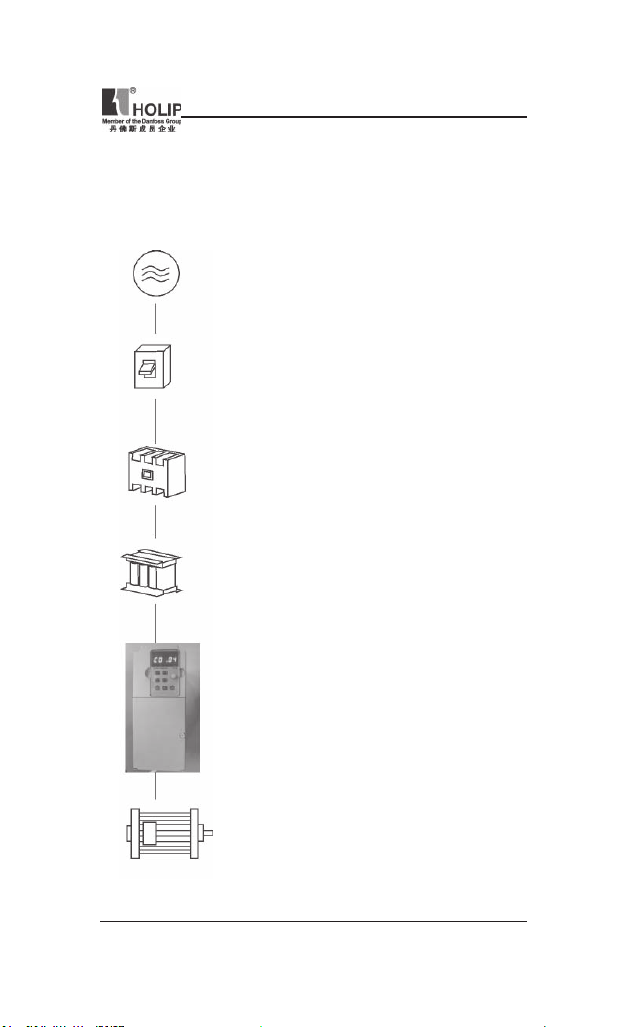
1. Main Circuit Wiring Schematic Diagram
Power supply:
● Verif y that the i nver te r’s r ate d volta ge coi ncid es
with AC p ower supply voltage to avoid a damage
of the inver ter.
No fuse breaker:
● Refer to the related list.
Ground fault circuit interrupter:
● Use one of anti-high harmonic.
Electromagnetic cont actor:
● Note: Do not use the electromagnetic contactor as
the on/off button of power supply for t he inver ter.
AC reactor:
● It is re commended to in st al l an AC reactor for
power factor improvement if the input capacit y is
more tha n 1000KVA.
Inverter:
● Be sur e to make correct c onnections of the main
ci rcu it wire s an d con t ro l sig nal wire s of the
inverter.
● Be s ure to make corre ct sett ing of para meters for
the inverter.
HLP-NV Series
HLP-NV Series
— 13 —
HLP-NV Series
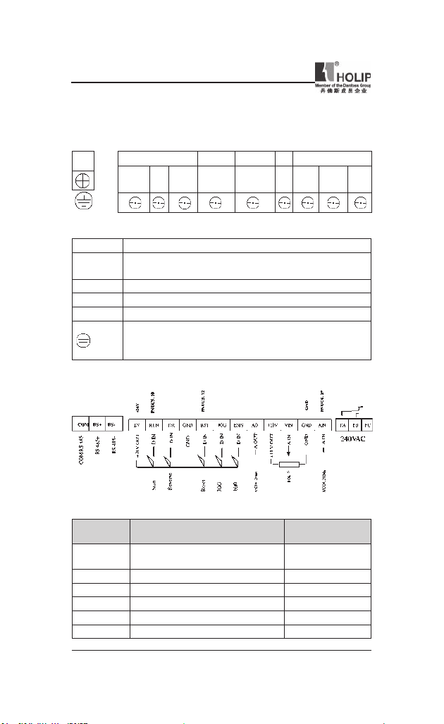
2. Description of Terminal Block
1)Arr angeme nt of Main ci rcuit Term inals
POWER MOTOR
R
L)
(
Function Description of Main circuit Terminals
Symbol Function Description
R S T
U.V.W Out put ter minal of the inve rter
+UDC BR Conne ctor for br aki ng resistor (optional).
-UDC Connector for DC reactor
2) Arra ngement of Control Circuit Terminals
In pu t ter min al of AC li ne power. (220V class:for bot h
single/three phase, si ngle phase connected to L and N)
Grou nd ter minal: the third method of g rounding for 220V
and special grou nding for 380 V of Electrical Engineering
Regulations.
T
S
-UDC +UDC BR U V W
(N)
Function Description of Control Ci rcuit Terminals
Symbol Function Descr iption
EV
RUN Multi- Dig ital Input Start
F/R Multi- Dig ital Input Reverse
GND Digital Ground (for 24V power)
RST Multi- Dig ital Input Reset
JOG Multi- Dig ital Input Jog
— 14 —
Common Terminal of Digital and
Control Signals ( +24V Power)
HLP-NV Series
Default setting
setting
HLP-NV Series
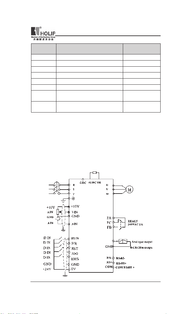
Symbol Function Descr iption
EMS Multi- Digital Input Bit0
AO Multi- Analog Output 0/4-20m A
+10V Power Supply for Analog Setti ng +10V
VIN Multi- A nalog input Voltage
GND Analog Ground
AIN Multi- A nalog input 0/4~20mA
FA FB FC Multi- Dig ital Output (Relay)
COM RS+ RS —
RS485 Com munication port
Default setting
setting
FA-FC:break
FA-FB:make
COM:Common for
RS+ and RS —
3. Basic Connection Diagram
The wiring of t he inver ter is d ivided i nto two parts, main circuit terminal
connectio ns an d cont rol ci rc uit te r mi na l connec tion s. The user can
see the m ai n ci rcuit terminal s an d th e contr ol circu it term in als af ter
remov in g the cover of encl os ur e. The ter mi nals must be co nnected
correctly as t he following wiring circuit diagrams.
The following diagram shows the Default setting standard con nection of
Model HLP-N V
HLP-NV Series
AO
— 15 —
HLP-NV Series
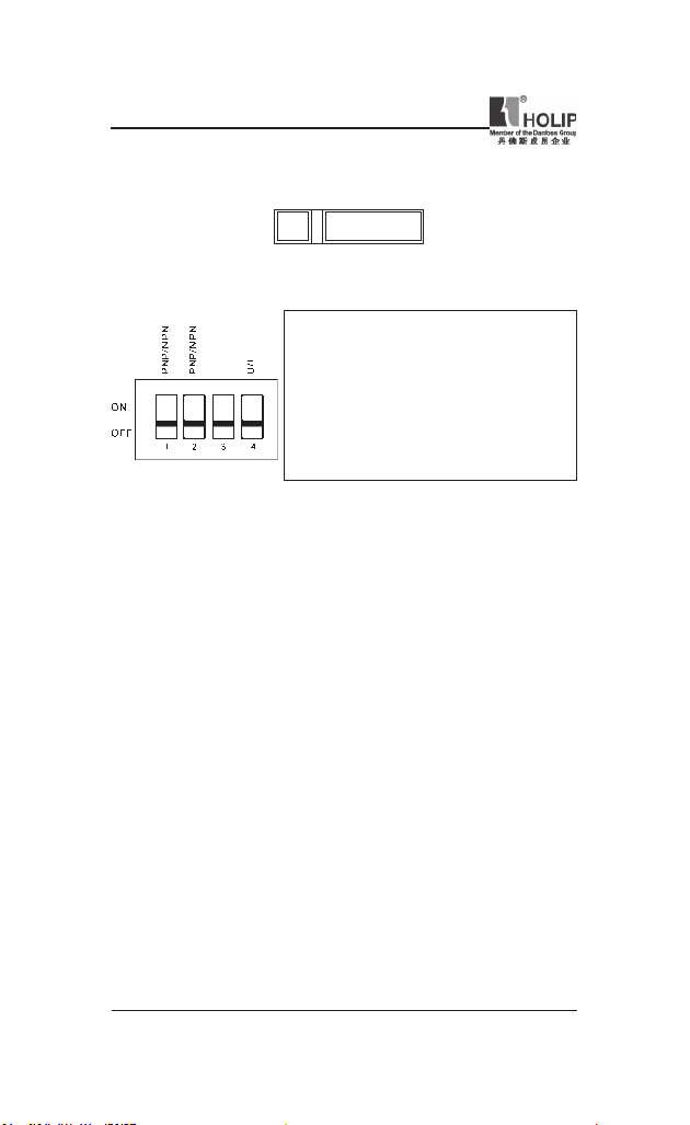
4. Switches
i. Bus ter mination:
OFF
Mark:Swit ch BUS TER enables termination of the RS485 port, term inals
RS+, RS-.
ii. Switches 1-4:
ATT EN TI ON: Para me te r C06.19 must be set acco rd in g to Switc h 4
position.
Warni ng: D o not oper ate swi tch es with pow er on the fr equ e nc y
converter.
BUS TER
ON
Switch 1: *OFF = PNP t erm inal JO G
ON = NPN te rmi nal JOG
Switch 2: *OFF = PNP t erm inals RUN,
F/R,R ST,EMS
ON = NPN te rmi nals RUN ,
F/R,R ST,EMS
Switch 3: No fun ction
Switch 4: *OFF = Termi nal VIN 0 — 10 V
ON = Termin al VI N 0/4 — 20 mA
* = default s etti ng
5. Precautions on Wiring
1) For the main circuit wiring:
● Wh ile wiring the sizes and specications of wires should be selected
an d the w iri ng sho ul d be exe cu t ed acc ord i ng to the elect ric al
engineeri ng regu lations to ensure the safety.
● It is better to use shielded wire or wire and conduit for power cord and
ground the shielded layer or t wo ends of wire conduit.
● Be sure to install a Non Fuse Breaker ( NFB) bet ween the power supply
and the in put te rminal s (L1.L2. L3). (If usin g grou nd fau lt circ ui t
inter rupter, please choose one corre sponding to high frequency)
● Ne ve r con ne ct AC powe r t o the outp ut ter min al ( U.V.W) of the
inverter.
● Outpu t wi res mus tn’t b e in tou ch of the metal part of t he inver ter
enclosu re, or it will result in ear th short-ci rcuit.
● Phase -s hift ing capacitors , LC, RC noise fi lte rs , etc, can never be
connected to t he output terminals of the inverter.
● The main ci rcuit wire must be enough far away from other control
equipments.
— 16 —
HLP-NV Series
HLP-NV Series
● W hen th e wiring be tw ee n the invert er and the motor exc ee ds 15
meter s (shielded wire) or 50 meters (No shielded wire), much higher
dV/dT will be produced inside the coil of t he motor, which wi ll cause
the destr uction to the interlay or insulation of t he motor. Please use a
dedicated AC motor for the inver ter or add a react or at the inverter.
● Plea se lower the car rier frequ enc y whe n there is a longer di stance
bet ween the inverter a nd the motor. Beca use t he higher t he carr ier
frequency is t he bigger t he leak age cur rent of h igh-order ha rmon ics in
the cables will b e. The leakage current will have unfavorable effect on
the inverter a nd other equipme nt.
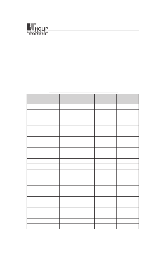
Specications of Non Fuse Breaker and Wire
Model
(A)
Input wire
mm
2
Output wire
2
mm
Control wire
2
mm
NFB
HLPNV0D1821A 16 2.5 2.5 0.5
HLPNV0D3721A 16 2.5 2.5 0.5
HLPNV0D7521A 16 2.5 2.5 0.5
HLPNV01D521A 16 2.5 2.5 0.5
HLPNV02D221A 32 4 4 0.5
HLPNV0D2523A 16 2.5 2.5 0.5
HLPNV0D3723A 16 2.5 2.5 0.5
HLPNV0D7523A 16 2.5 2.5 0.5
HLPNV01D523A 32 2.5 2.5 0.5
HLPNV02D223A 32 4 4 0.5
HLPNV03D723A 32 4 4 0.5
HLPNV0D3743A 16 2.5 2.5 0.5
HLPNV0D7543A 16 2.5 2.5 0.5
HLPNV01D543A 16 2.5 2.5 0.5
HLPNV02D243A 16 2.5 2.5 0.5
HLPNV03D043A 16 2.5 2.5 0.5
HLPNV04D043A 32 4 4 0.5
HLPNV05D543A 32 4 4 0.5
HLPNV07D543A 40 6 6 0.5
HLPNV001143A 63 6 6 0.5
HLPNV001543A 100 6 6 0.5
HLPNV18D543A 100 10 10 0.5
HLPNV002243A 100 16 16 0.5
Attention: The parameters i n the list are only for reference and should not
be regarded as st anda rd.
HLP-NV Series
— 17 —
HLP-NV Series
2) For control circuit wi ring (signal line)
● The signal line should be separately laid in a different conduit with t he
main ci rcuit wire to avoid any possible i nterference.
● Please use the shielded cable wit h the size of 0.5-2mm2 for signal lines.
● Use the control terminals on the control panel correctly accor ding t o
your needs.
3) Grounding
● Grounding terminal E. Be sure to make cor rect g round ing
220V class: The third grounding method (Grou nding resistance should
be 100Ω or lower.)
380V class: The special third grounding met hod (Grounding resistance
should be 10Ω or lower.)
● Choose grounding w ires according to the basic length and siz e of the
technical require ments of the electric equipment.
● Do avoid shar ing ground ing wire with other large power equ ipment
such as el ec tr ic welder, power ma ch in e, et c. The gr ou nd in g wir e
should be kept away from the power supply wire s for la rge power
equipment.
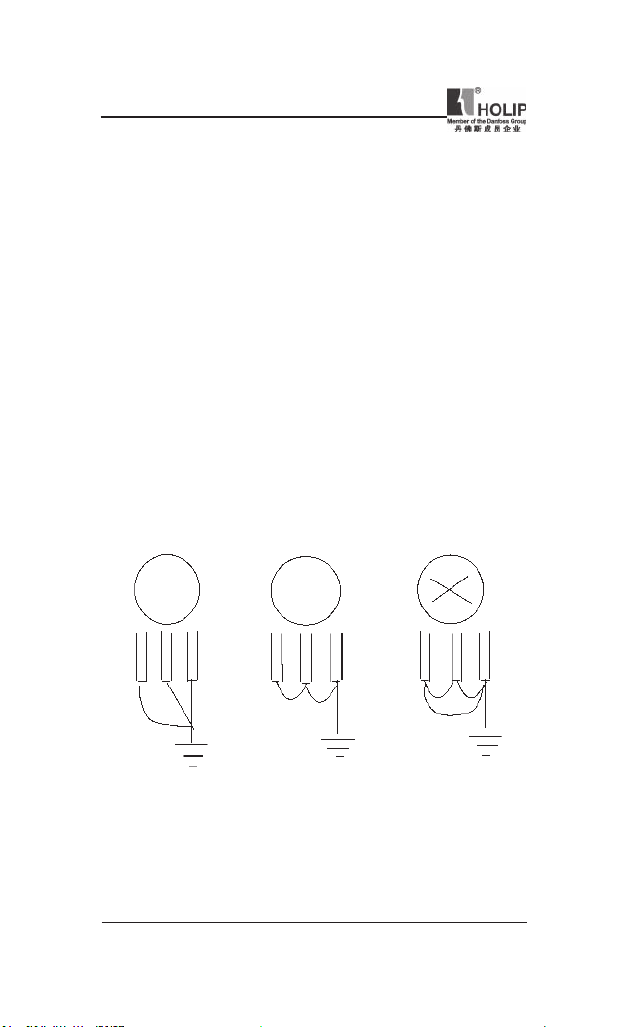
● The grounding method for several inverters together should be done as
the rst and sec ond diag rams below. Avoid the third loop.
● The groundi ng wire must be as short as p ossible.
(1) Good (2) Good (3) Not good
— 18 —
HLP-NV Series
HLP-NV Series
VI. Instruction of the LCP Digital Operator
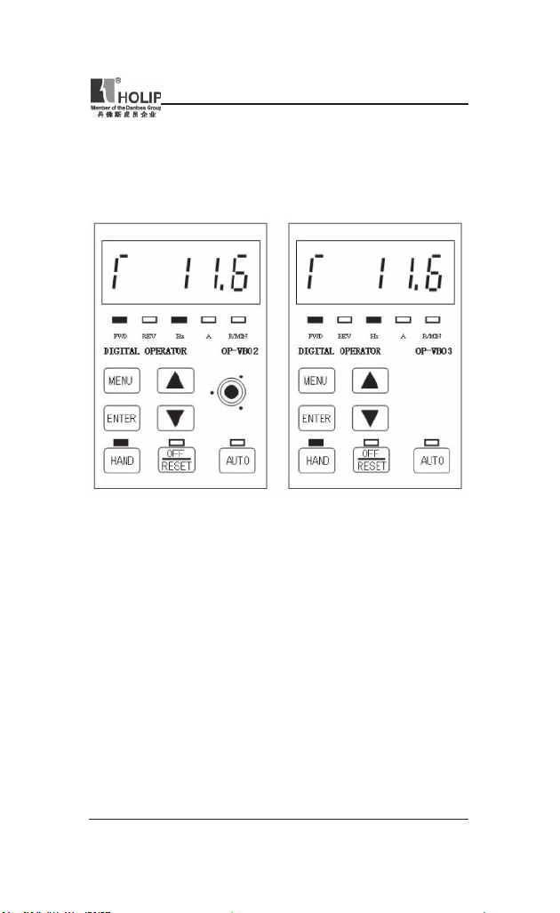
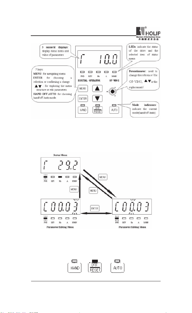
1. Description of the LCP Digital Operator
LCP with potentiometer
2. Programming with LCP
2.1. LCP introduction:
1. 5 numeric d isplays
2.
8 LEDs: FWD、REV、Hz、A、R/MIN、HAN D、OFF/RESET、AUTO
3. 7 keys: MENU、ENTER、▲、▼、HAN D、OFF/RESET、AUTO
4. 1 potent iometer (only for type OP-VB02).
LCP without potentiometer
HLP-NV Series
— 19 —
HLP-NV Series
2.2
General Operation
.
The me nu syst em allows op er ators to nav igate th ro ug h hierarchica l
menus which contain related menu items. The top-level menu c onta ins
two menu items: statu s menu、parameter editing menu. These two items
can be explored by pressing MENU key:
2.3
Mode keys and potent iometer
.
Mode Keys are u sed to send Hand, OFF/Reset, Auto request to the dr ive.
It is related to the reference site selection ( Local or Remote).The yellow
LEDs ind icate the certain active mode.
— 20 —
HLP-NV Series
HLP-NV Series
The HAND, OFF/RESET a nd AUTO key ca n be dis abled by chang ing
parameter(C00.40、C00.41、C00.42).
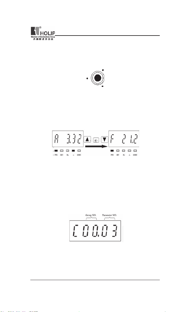
Potentiometer: used for set ting t he refere nce only.
The pot entiometer can be used in bot h hand and auto mode wit h different
functionality:
In Ha nd mode the potentio me te r will work as the arr ow key s – i .e.
controlli ng the local refere nce fr om 0 to max reference (C03.03). If the
LCP does not c ont ain a pot entiom ete r, the ar row keys ar e used to set
reference:
In auto mode the potentiometer will act a s an ext ra analog input to the
system. It is selected/deselected as the other analog input s (see C03.15 to
C03.18).
C06.81, C06.82 are used to scale the potentiometer input.
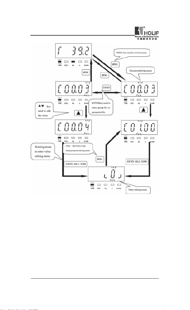
2.4 Parameter editing menu and st atus menu
2.4.1 Parameter editing menu:
HLP-NV Series
— 21 —
HLP-NV Series
Parameter set ting example:
How to set C03.17 to 21
1. Pressing MENU key to let the display go to parameter ed iting menu.
2. Pressing▲▼key to select group No.(C03.00)
3. Pressing ENTER key t o edit par ameter No.,then p ressing▲▼key to
select paramet er No. (C03.17).
4. Hold in g down EN TER key to go to the va lue edtin g menu , then
pressi ng▲▼to edit the value of the parameter to 21,then holding down
ENTER key to conrm t he change till “END”was displayed.
— 22 —
HLP-NV Series
HLP-NV Series
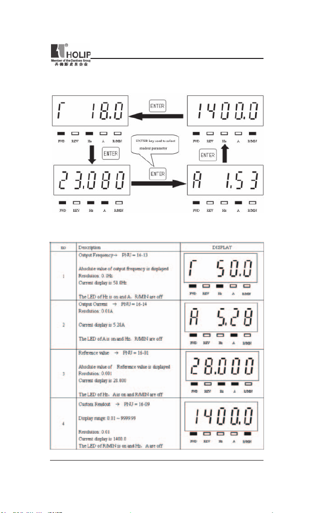
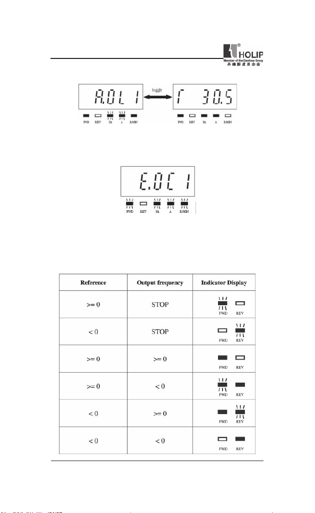
2.4.2 Readout and indicator:
The readout par amete rs toggled by pressing ENTER key:
The below table shows the screen of displayi ng every readout parameter
HLP-NV Series
— 23 —
HLP-NV Series
Warning descr iption:
when war ning o ccur red , the LEDs of Hz、A w ill ash a nd R/MIN will
be lit.
Alar m description:
when ala rm occur red, the LED s of Hz、A and R/ MIN will f lash,an d
the drive will trip. A trip ca n be cancelle d by pressing reset or, in some
cases, aut omatically. A locked trip ca nbe cancel led by cutting off mains
and restarting the drive.
The motor direction is indicated by the led s of FWD and REV:
— 24 —
HLP-NV Series
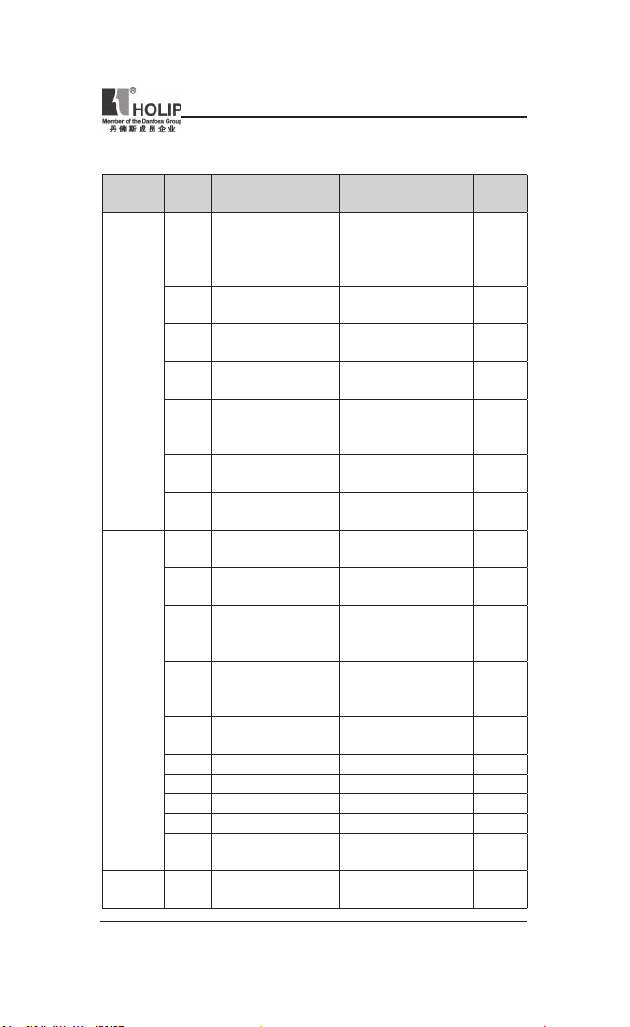
VII. Parameter Overview
Function
Item
Operation
/ Display
Load /
Motor
Fuction Description
Code
Op er. St at e at Power-
C00.04
up [Hand]
Cu st om Re ad ou t Min
C00.31
Scale
Custom Readout Max
C00.32
Scale
C00.40 [Hand on] Key on LCP
[Off / Re se t] Ke y on
C00.41
LCP
C00.42 [Auto on] Key on LCP
C00.60 Menu locked
C01.00 Conguration Mode
Motor Cont rol
C01.01
Principle
C01.03 Torque Character istics
Local Mode
C01.05
Cong urat ion
Motor Power
C01.20
[kW] [HP]
C01.22 Motor Voltage 50 — 999 V **
C01.23 Motor Frequency 20 — 400 Hz 50 Hz
C01.24 Motor Current 0.01 — 26.00 A **
C01.25 Motor Nom inal Sp eed 100 — 9999 r pm **
Automatic Motor
C01.29
Tuning (AMT )
C01.30 Stator Resistance (R s)
HLP-NV Series
Range&Function
explanation
[0] Resume
*[1] Forced sto p, ref =
old
[2] Forced stop, ref = 0
0.00 – 9999.00 0.00
0.00 – 9999.00 100.00
[0] Disabled
*[1] Enabled
[0] Disable All
*[1] Enable All
[2] Enable Reset O nly
[0] Disabled
*[1] Enabled
[0]Disabled
[1]Enabled
*[0] Speed open loop
[3] Process
[0] V/F
*[1] VVC+
*[0] Constant torque
[2] Automatic Energy
Optim.
[0] Speed Open Loop
*[2] As cong i n param.
C01.00
0.09 kW / 0.12 HP …. 11
kW / 15 HP
*[0] Off
[2] Enable AMT
[Ohm] * Dep. on mot or
data
Default
setting
1
1
1
1
0
0
1
0
2
**
0
**
HLP-NV Series
— 25 —
Loading…
- Addeddate
- 2021-02-05 22:19:32
- Identifier
- manuallib-id-1328
- Identifier-ark
- ark:/13960/t6455tj0d
- Ocr
- tesseract 4.1.1
- Ocr_autonomous
- true
- Ocr_detected_lang
- zh
- Ocr_detected_lang_conf
- 1.0000
- Ocr_detected_script
-
HanS
HanT
Japanese
Latin
- Ocr_detected_script_conf
-
0.3802
0.3802
0.0965
0.1121
- Ocr_module_version
- 0.0.11
- Ocr_parameters
- -l chi_sim+HanS
- Page_number_confidence
- 39.50
comment
Reviews
There are no reviews yet. Be the first one to
write a review.
688
Views
DOWNLOAD OPTIONS
Temporarily Unavailable
DAISY
For users with print-disabilities
Uploaded by
chris85
on
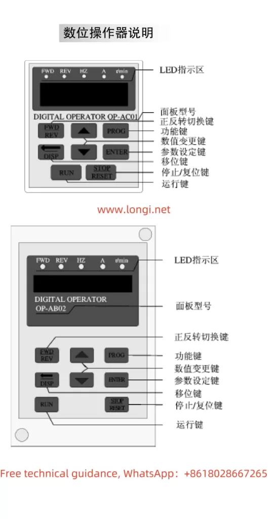
I. Introduction to Operation Panel Functions and Parameter Settings
The HOLIP Inverter HLP-A series boasts a comprehensive operation panel that allows users to perform parameter settings, monitor operating status, and diagnose faults. The operation panel primarily includes a display screen, directional keys, set keys, run keys, stop keys, and other functional keys.
Setting and Resetting Passwords
To protect against unauthorized modification of inverter parameters, the HLP-A series supports password protection. Users can enable password protection by setting parameter CD010 to 1, at which point all parameters except CD010 become unmodifiable. To reset the password, simply set CD010 back to 0.
Locking Parameters
To prevent non-maintenance personnel from accidentally modifying parameters, users can lock all parameters except CD010 by setting CD010 to 1. Once locked, only the correct password (set through parameter CD011) can unlock the parameters for modification.
Initializing Parameters
When it is necessary to restore the inverter to its factory settings, users can set parameter CD011 to 08 and then press the run and stop keys simultaneously. The inverter will automatically restart and revert to its factory settings.
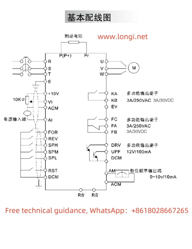
II. Terminal Forward/Reverse Control and External Potentiometer Frequency Adjustment
Terminal Forward/Reverse Control
The HLP-A series inverter supports forward/reverse control via external terminals. Users need to set the multi-function input terminal FOR to forward (parameter CD050=02) and REV to reverse (parameter CD051=03). Then, by controlling the on/off state of these terminals with external switches, motor forward/reverse control can be achieved.
External Potentiometer Frequency Adjustment
External potentiometer speed control is a commonly used method for variable frequency speed control. Users need to set the inverter’s operation command source to external terminals (parameter CD033=1) and the operation frequency source to external analog (parameter CD034=1). Connect the potentiometer’s center tap to the VI terminal and its ends to the +10V and ACM terminals, respectively. By adjusting the potentiometer’s resistance, the inverter’s output frequency can be changed, thereby achieving motor speed control.
III. Fault Codes and Solutions
The HLP-A series inverter features comprehensive fault protection functions. When a fault occurs, the inverter will display the corresponding fault code. Below are some common fault codes, their meanings, and solutions:
E.OC.A (Overcurrent During Acceleration)
Meaning: The inverter experiences overcurrent during acceleration.
Solution: Check for short circuits or partial short circuits in the motor, and ensure good insulation of output wires; extend the acceleration time; check the inverter configuration for reasonableness and increase the inverter capacity if necessary; reduce the torque boost setting.
E.GF.S (Ground Fault)
Meaning: The inverter output is short-circuited to ground.
Solution: Check for short circuits in motor connections and ensure good insulation of output wires; if the fault cannot be resolved, contact the manufacturer for repair.
E.OU.S (Overvoltage During Stopping)
Meaning: The inverter experiences overvoltage during stopping.
Solution: Extend the deceleration time or install a braking resistor; improve the grid voltage quality and check for sudden voltage fluctuations.
E.OL.A (Inverter Overload)
Meaning: The inverter is overloaded.
Solution: Check if the inverter capacity is too small and increase it if necessary; check for stuck mechanical loads; reset the V/F curve.
E.OT.A (Motor Overtorque)
Meaning: The motor experiences overtorque.
Solution: Check for fluctuations in mechanical loads; check if the motor configuration is too small; check for deterioration in motor insulation due to overheating; check for significant voltage fluctuations; check for phase loss; check for increased mechanical loads.
IV. Conclusion
The HOLIP Inverter HLP-A series user manual provides users with detailed operation guides and fault solutions. By understanding the operation panel functions, mastering terminal control and potentiometer speed adjustment methods, and being familiar with fault code meanings and solutions, users can better utilize and maintain the inverter, ensuring its stable operation and extended service life. In practical applications, users should strictly follow the instructions in the manual for operation and maintenance to ensure the performance and safety of the inverter.
Holip HLP-A100 Series user guide recommended for: HLP-A Series, HLP-C100 Series, HLP-P Series, MG 2700, INVB Series.
The Holip HLP-A100 Series Inverter manual (Holip Operating manual, 187 pages) is completely safe to download (last scan date: 07/11/2024). You can rest assured of your safety when interacting with Holip HLP-A100 Series document.
1
30 FOOT (9 Meter) TOWER KIT for WHISPER 500
Owner’s manual Guide: Southwest Windpower 30 FOOT (9 Meter) TOWER KIT for WHISPER 500 (1DAYJ3, Upd.24/12/2024)
44
875
193
2
MA10K-PRO
Operation & user’s manual Airthereal Inverter Operation & user’s manual (File: airthereal-ma10k-pro-operation-user-s-manual-58, 31.03.2025)
58
871
210
3
PV-ezRack SolarRoof Isolator Shade
Installation manual #OIWD7A: PV-ezRack SolarRoof Isolator Shade Inverter Installation manual
11
533
118
5
U-140PEY1E8
100
710
135
6
S-36PU1E5A
Service manual #1DNW1R: S-36PU1E5A Air Conditioner Service manual
693
433
87
7
Onan HGJAA Series
Service manual CUMMINS Portable Generator Service manual (File: cummins-onan-hgjaa-series-service-manual-202, 03.12.2024)
202
971
204
8
BATTERY EXTENDER BE01257
19
485
73
9
MM AE Series
Owner’s manual MM AE Series (Inverter ePDF Guide, #7J5I86)
48
551
116
Holip HLP-A100 Series Operating manual
- Holip
- Inverter
- Operating manual for Holip HLP-A100 Series
- holip-hlp-a100-series-operating-manual-187_manual.pdf
- 187 |
Pages Preview:
Document Transcription:
See Details
Download