
Архивный товар
Товар снят с продажи, подберите рекомендованный аналог
Информация о товаре
Подбор рекомендованного аналога
Заполните форму, и мы обязательно с Вами свяжемся
Похожая группа товаров
Предприятие обеспечивает полный производственный цикл,
включая производство пластин, плит, элементов рам и других комплектующих.
Локализация достигает 95%, мощность предприятия составляет более 20 тыс.
изделий в год.
- Напряжение питания
- 230 В перем.тока 50Гц; 1,5 ВА
- Примечание
- Лицевая панель
- Количество реле
- 2 (10А) 2 (6А)
- Поддержка сетевых карт
- да
- Количество цифровых входов
- 2
- Количество аналоговых входов
- 3
- Встроенная сетевая карта
- нет
Руководство
Скачать
Письмо о замене
Письмо о замене
Письмо о замене
Скачать
- Напряжение питания
- 230 В перем.тока 50Гц; 1,5 ВА
- Управление компрессором
- да
- Управление оттаиванием
- да
- Модель
- EKC202D
- Поддержка сетевых карт
- да
- температура среды при хранении
- от -40 до +70 °С
- Число испарителей
- 1
- Управление вентилятором
- да
- Управление светом
- да
- Количество реле
- 2 (10А) 2 (6А)
- Количество цифровых входов
- 2
- Примечание
- Лицевая панель
- температура среды при эксплуатации
- от 0 до +55 °С
- Встроеная сетевая карта
- нет
- Количество входов
- 3 аналоговых, 2 цифровых
- Количество аналоговых выходов
- 0
- Встроенная сетевая карта
- нет
- Количество аналоговых входов
- 3
Руководство
Скачать
Письмо о замене
Письмо о замене
Письмо о замене
Скачать
Товары серии
|
Название и |
Напряжение питания | Примечание | Количество реле | Поддержка сетевых карт | Количество цифровых входов | Количество аналоговых входов | Встроенная сетевая карта | ||
|---|---|---|---|---|---|---|---|---|---|
|
084B8521 EKC 202A Контроллер испарителя и уровня(пр. класс 2551201918) |
230 В перем.тока 50Гц; 1,5 ВА | Лицевая панель | 2 (10А) | да | 1 | 2 | нет | ||
|
|
|||||||||
|
084B8522 EKC 202B Контроллер испарителя и уровня |
230 В перем.тока 50Гц; 1,5 ВА | Лицевая панель | 3 (10А) 1 (6А) | да | 1 | 2 | нет | ||
|
|
|||||||||
|
084B8622 EKC 202B Контроллер испарителя и уровня |
230 В перем.тока 50Гц; 1,5 ВА | Лицевая панель | 2 (10А) 1 (6А) | да | 1 | 2 | нет | ||
|
|
|||||||||
|
084B8691 EKC 202B Контр-р исп.и ур. |
230 В перем.тока 50Гц; 1,5 ВА | Лицевая панель | 2 (10А) 1 (6А) | да | 1 | 2 | нет | ||
|
|
|||||||||
|
084B8523 EKC 202C Контроллер испарителя и уровня |
230 В перем.тока 50Гц; 1,5 ВА | Лицевая панель | 2 (10А) 2 (6А) | да | 1 | 2 | нет | ||
|
|
|||||||||
|
084B8543 EKC202C MS Контроллер испарителя |
230 В перем.тока 50Гц; 1,5 ВА | Лицевая панель | 2 (10А) 2 (6А) | да | 1 | 2 | нет | ||
|
|
|||||||||
|
084B8536 EKC 202D Контроллер испарителя и уровня(пр. класс 2551201918) |
230 В перем.тока 50Гц; 1,5 ВА | Лицевая панель | 2 (10А) 2 (6А) | да | 2 | 3 | нет | ||
|
|
|||||||||
|
084B8636 ЕKC 202D Контроллер испарителя и уровня |
230 В перем.тока 50Гц; 1,5 ВА | Лицевая панель | 2 (10А) 2 (6А) | да | 2 | 3 | нет | ||
|
|
Controller for temperature control
— EKC 202D
Manual
2 Manual RS8EE202 © Danfoss 08-2010 EKC 202D
Introduction
Application
• The controller is used for temperature control refrigeration
appliances in supermarkets.
• With many predened applications one unit will oer you
several options. Flexibility has been planned both for new
installations and for service in the refrigeration trade.
Principle
The controller contains a temperature control where the signal
can be received from one or two temperature sensors.
The thermostat sensors are either placed in the cold air ow after
the evaporator, in the warm air ow just before the evaporator,
or both. A setting will determine how great an inuence the two
signals are to have on the control.
A measurement of the defrost temperature can be obtained
directly through the use of an S5 sensor or indirectly through
the use of the S4 measurement. Four relays will cut the required
functions in and out – the application determines which.
The options are the following:
• Refrigeration (compressor or relay)
• Fan
• Defrost
• Rail heat
• Alarm
• Light
The dierent applications are described on page 6.
Advantages
• Several applications in the same unit
• The controller has integrated refrigeration-technical functions,
so that it can replace a whole collection of thermostats and
timers
• Buttons and seal imbedded in the front
• Easy to remount data communication
• Two temperature references
• Digital inputs for various functions
• Clock function with super cap backup
Contents
Introduction …………………………………………………………………………………………. 2
Operation ……………………………………………………………………………………………… 3
Applications …………………………………………………………………………………………. 6
Survey of functions ……………………………………………………………………………… 7
Operation …………………………………………………………………………………………….16
Menu survey ………………………………………………………………………………………..17
Override ………………………………………………………………………………………………. 19
Ordering ………………………………………………………………………………………………19
Connections ………………………………………………………………………………………..20
Data ………………………………………………………………………………………………………21
EKC 202D Manual RS8EE202 © Danfoss 08-2010 3
Operation
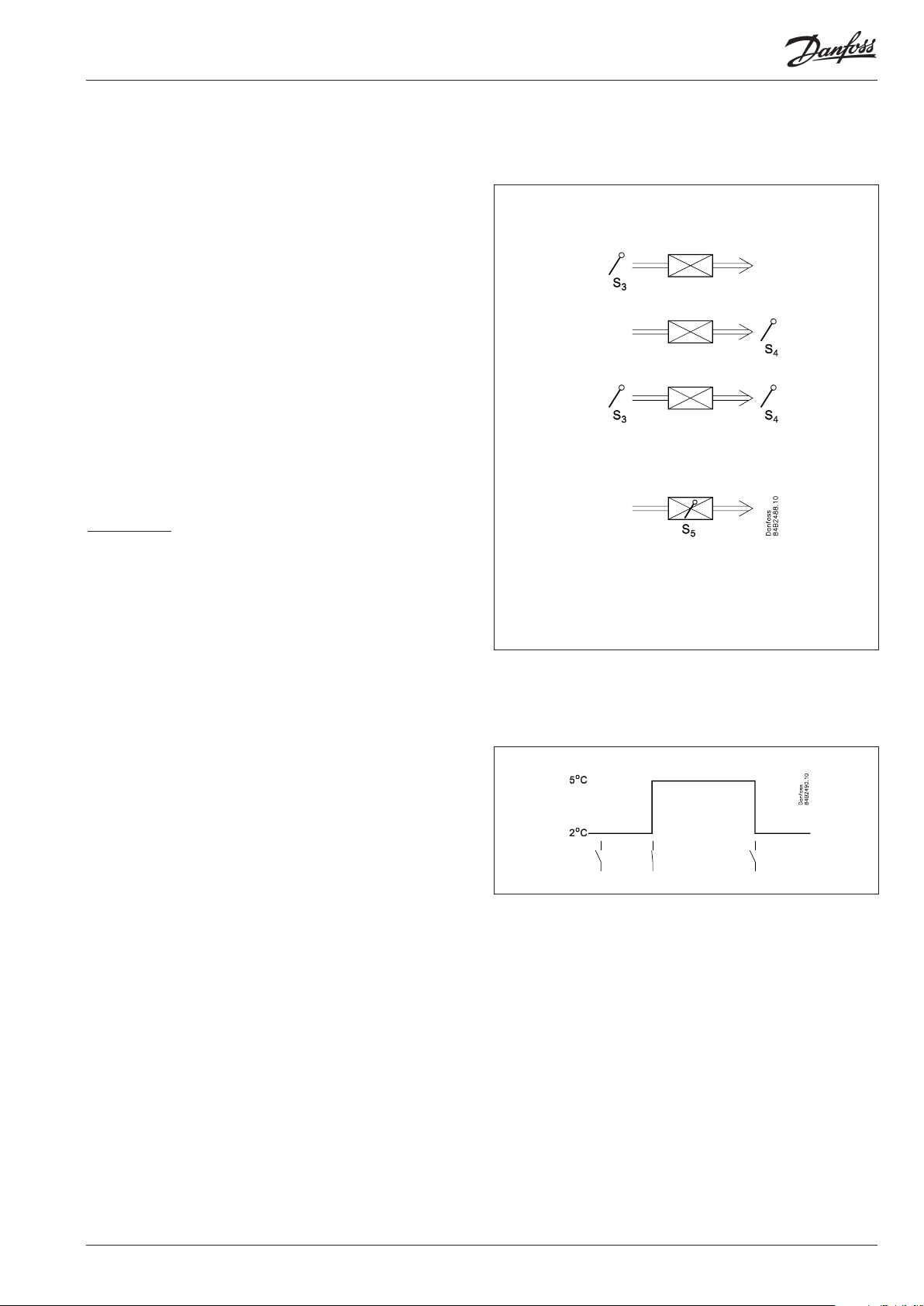
Sensors
Up to two thermostat sensors can be connected to the controller.
The relevant application determines how.
A sensor in the air before the evaporator:
This connection is primarily used when control is based on area.
A sensor in the air after the evaporator:
This connection is primarily used when refrigeration is controlled
and there is a risk of a too low temperature near the products.
A sensor before and after the evaporator:
This connection oers you the possibility of adapting the
thermostat, the alarm thermostat and the display to the relevant
application. The signal to the thermostat, the alarm thermostat
and the display is set as a weighted value between the two
temperatures, and 50% will for example give the same value from
both sensors.
The signal to the thermostat, the alarm thermostat and the display
can be set independently of one another.
Defrost sensor
The best signal concerning the evaporator’s temperature
is obtained from a defrost sensor mounted directly on the
evaporator. Here the signal may be used by the defrost function,
so that the shortest and most energy-saving defrost can take
place.
If a defrost sensor is not required, defrost can be stopped based
on time, or S4 can be selected.
Change of temperature reference
In an impulse appliance, for example, used for various product
groups. Here the temperature reference is changed easily with
a contact signal on a digital input. The signal raises the normal
thermostat value by a predened amount. At the same time the
alarm limits with the same value are displaced accordingly.
4 Manual RS8EE202 © Danfoss 08-2010 EKC 202D
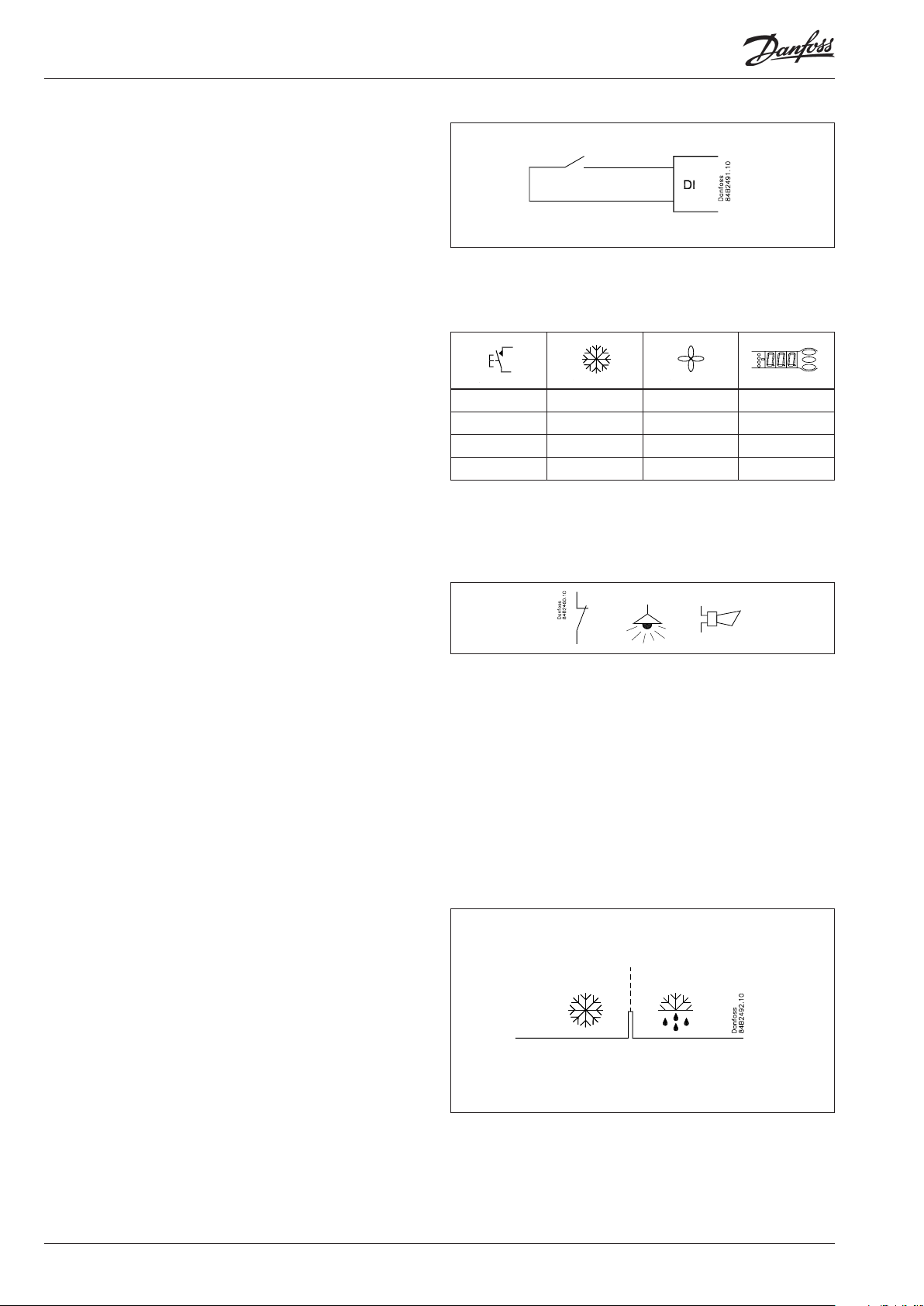
Digital inputs
There are two digital inputs both of which can be used for one of
the following functions:
— Case cleaning
— Door contact function with alarm
— Starting a defrost
— Coordinated defrost
— Change-over between two temperature references
— Retransmission of a contact’s position via data communication
Case cleaning function
This function makes it easy to steer the refrigeration appliance
through a cleaning phase. Via three pushes on a switch you
change from one phase to the next phase.
The rst push stops the refrigeration – the fans keep working
”Later”: The next push stops the fans
”Still later”: The nal push restarts refrigeration
The dierent situations can be monitored on the display.
On the network a cleaning alarm is transmitted to the system unit.
This alarm can be ”logged” so that proof of the sequence of events
is provided.
— + + °C
1 ÷ + Fan
2 ÷ ÷ O
3 + + °C
Door contact function
In cold rooms and frost rooms the door switch can turn the light
on and o, start and stop the refrigeration and give alarm if the
door has remained open for too long.
Defrost
Depending on the application you may choose between the
following defrost methods:
Natural: Here the fans are kept operating during the defrost
Electric: The heating element is activated
Brine: The valve is kept open so that the brine can ow
through the evaporator
Start of defrost
A defrost can be started in dierent ways;
Interval: Defrost is started at xed time intervals, e.g., every
eight hour
Refrigeration time:
Defrost is started at xed refrigeration time inter-
vals, in other words, a low need for
refrigeration will ”postpone” the coming defrost
Schedule: Here defrost can be started at xed times during
the day and night. However, max. 6 times
Contact: Defrost is started with a contact signal on a digital
input
Network: The signal for defrost is received from a system unit
via the data communication
S5 temp In 1:1 systems the eciency of the evaporator can
be monitored. Icing-up will start a defrost.
Manual: An extra defrost can be activated from the control ler’s lower-most button
All the mentioned methods can be used at random – if just one of
them is activated a defrost will be started.
EKC 202D Manual RS8EE202 © Danfoss 08-2010 5
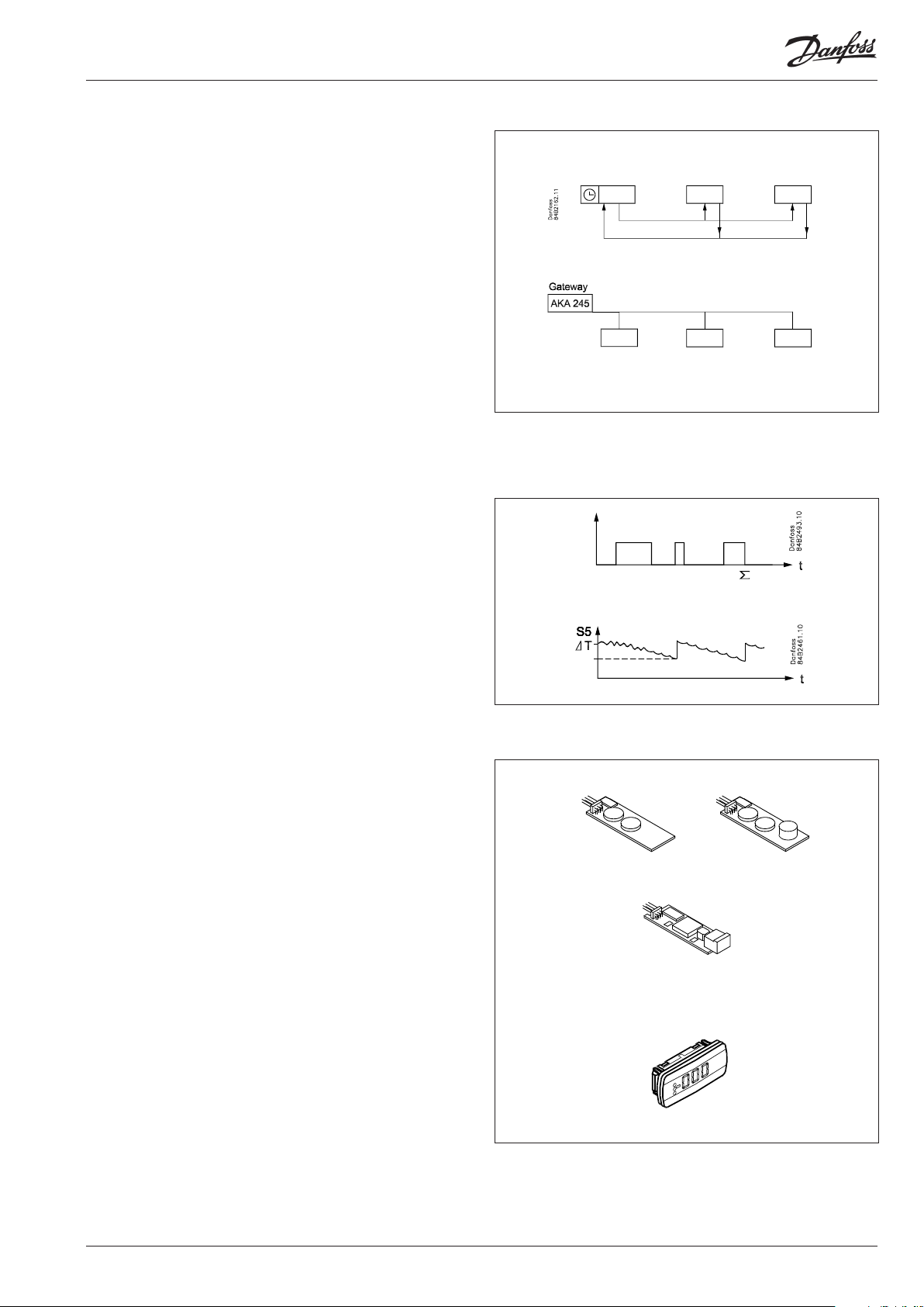
Coordinated defrost
There are two ways in which coordinated defrost can be arranged.
Either with wire connections between the controllers or via data
communication.
Wire connections
One of the controllers is dened to be the controlling unit and
a battery module may be tted in it so that the clock is ensured
backup. When a defrost is started all the other controllers will
follow suit and likewise start a defrost. After the defrost the individual controllers will move into waiting position. When all are in
waiting position there will be a change-over to refrigeration.
(If just one in the group demands defrost, the others will follow
suit).
Defrost via data communication
All controllers are tted with a data communication module,
and via the override function from a gateway the defrost can be
coordinated.
Defrost on demand
1 Based on refrigeration time
When the aggregate refrigeration time has passed a xed time,
a defrost will be started.
2 Based on temperature
The controller will constantly follow the temperature at S5.
Between two defrosts the S5 temperature will become lower
the more the evaporator ices up (the compressor operates for a
longer time and pulls the S5 temperature further down). When
the temperature passes a set allowed variation the defrost will
be started.
This function can only work in 1:1 systems
Extra module
• The controller can afterwards be tted with an insertion module
if the application requires it.
The controller has been prepared with a plug, so the module
simply has to be pushed in
— Battery module
The module guarantees voltage to the controller if the supply
voltage should drop out for more than four hours. The clock
function can thus be protected during a power failure.
— Battery and buzzer module
As above + sound buzzer
— Data communication
If you require operation from a PC, a data communication module has to be placed in the controller.
• External display
If it is necessary to indicate the temperature on the front of
refrigeration appliance, a display can be mounted. The extra display will show the same information as the controller’s display,
but does not incorporate buttons for operation.
6 Manual RS8EE202 © Danfoss 08-2010 EKC 202D
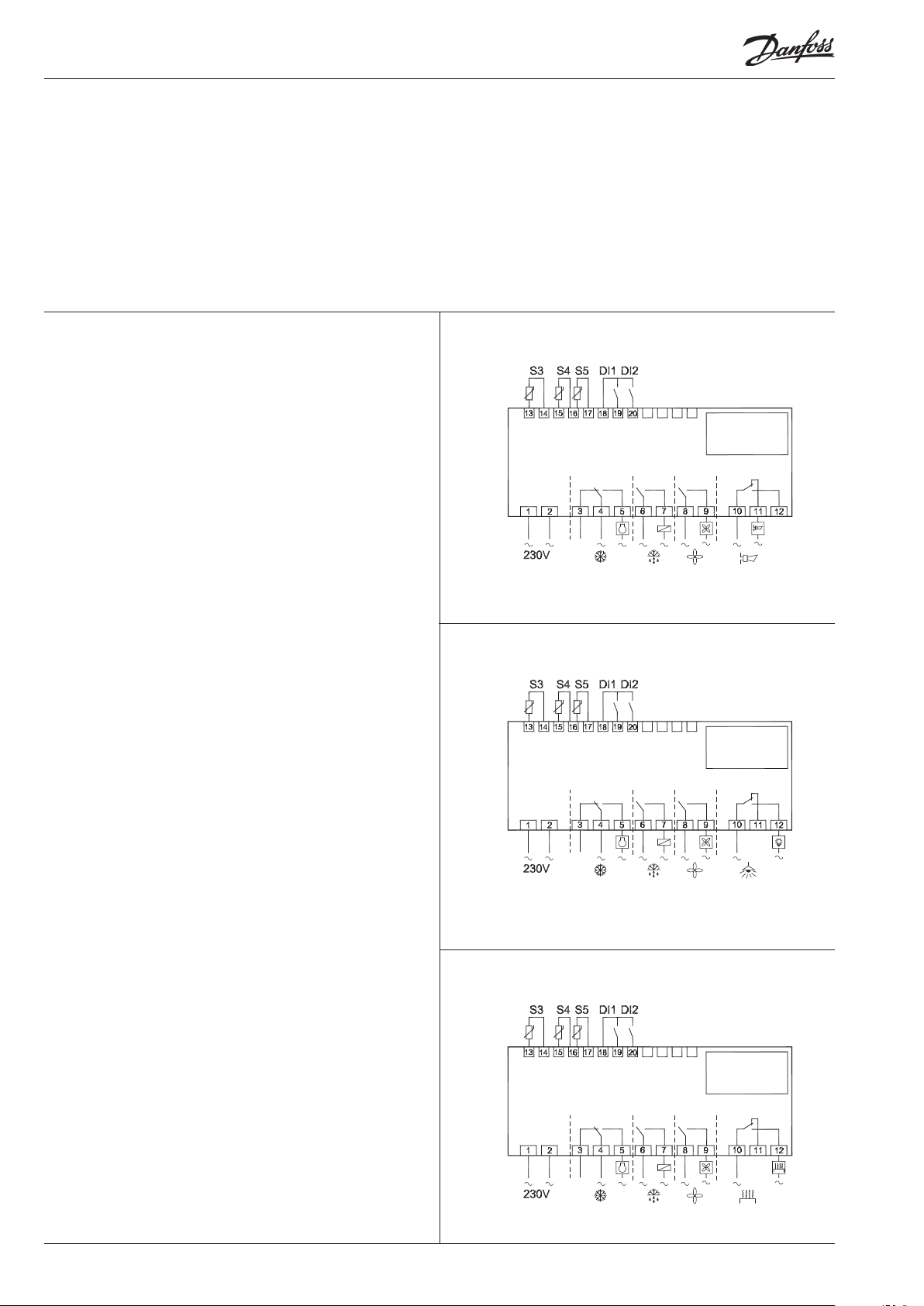
Applications
Here is a survey of the controller’s eld of application.
A setting will dene the relay outputs so that the controller’s interface will be targeted the chosen application.
On page 17 you can see the relevant settings for the respective
wiring diagrams.
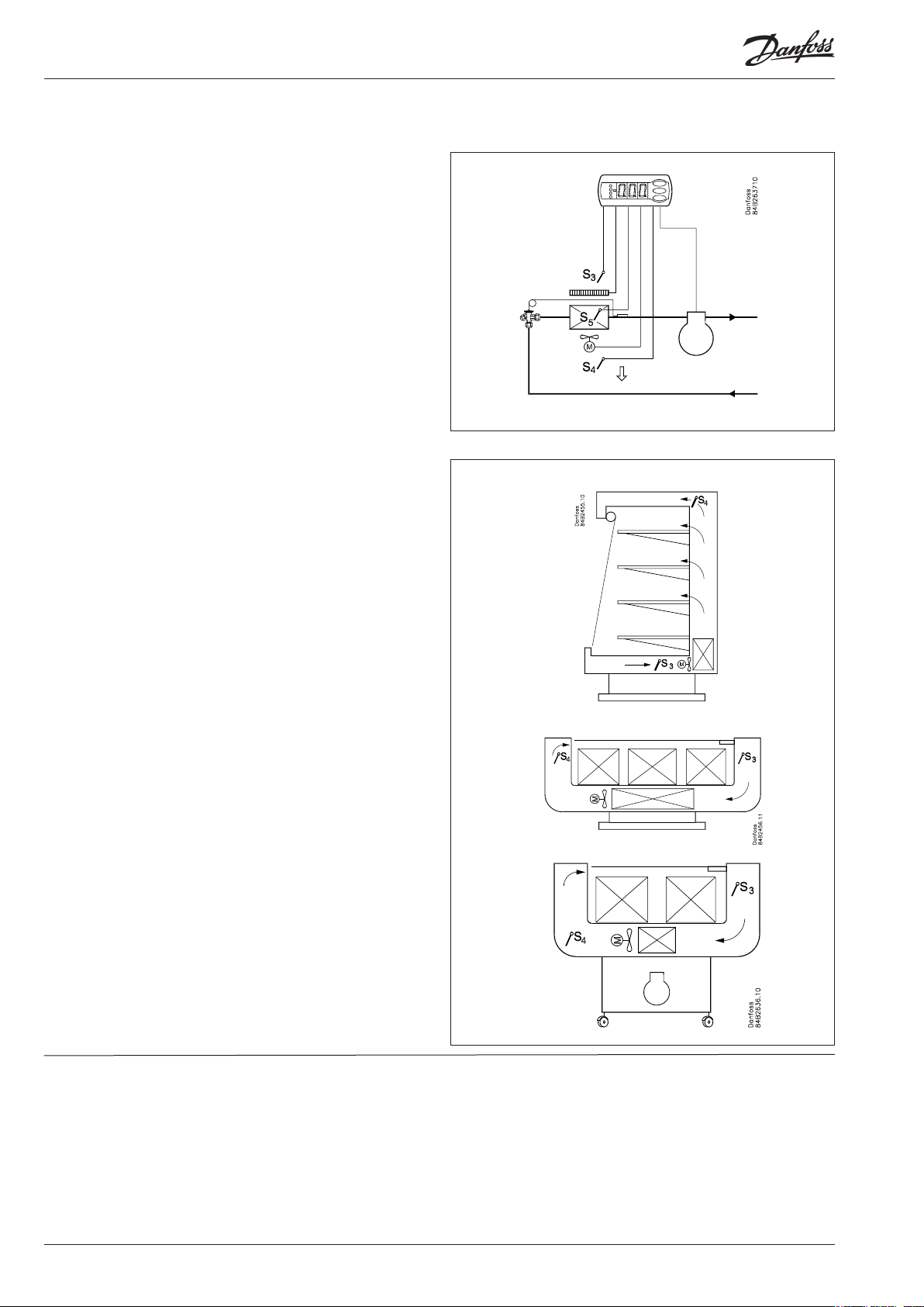
S3 and S4 are temperature sensors. The application will determine whether either one or the other or both sensors are to be
used. S3 is placed in the air ow before the evaporator. S4 after
the evaporator.
A percentage setting will determine according to what the
control is to be based. S5 is a defrost sensor and is placed on the
evaporator.
DI1 and DI2 are contact functions that can be used for one of the
following functions: door function, alarm function, defrost start,
external main switch, night operation, change of thermostat reference, appliance cleaning, forced refrigeration or coordinated
defrost. See the functions in settings o02 and o37.
Refrigeration control with one compressor
The functions are adapted to small refrigeration systems which
may be either refrigeration appliances or coldrooms.
The three relays can control the refrigeration, the defrost and the
fans, and the fourth relay can be used for either alarm function,
light control or rail heat control.
• The alarm function can be linked up with a contact function
from a door switch. If the door remains open longer than allowed an alarm is triggered.
• The light control can also be linked up with a contact function
from a door switch. An open door will switch on the light and
it will remain lit for two minutes after the door has been closed
again.
• The rail heat function can be used in refrigeration or freezing
appliances or on the door’s heating element for frostrooms.
The fans can be stopped during defrost and they may also follow
a door switch’s open/close situation.
There are several other functions for the alarm function as well
as the light control, rail heat control and fans. Please refer to the
respective settings.
1
2
3
EKC 202D Manual RS8EE202 © Danfoss 08-2010 7
Survey of functions
Function Para-
meter
Normal display
Normally the temperature value from one of the two thermostat sensors S3 or S4 or a
mixture of the two measurements is displayed.
In o17 the ratio is determined.
Thermostat Thermostat control
Set point
Regulation is based on the set value plus a displacement, if applicable. The value is set
via a push on the centre button.
The set value can be locked or limited to a range with the settings in r02 and r 03.
The reference at any time can be seen in ”u28 Temp. ref”
Differential
When the temperaure is higher than the reference + the set dierential, the compressor relay will be cut in. It will cut out again when the temperature comes down to the
set reference.
Ref. Dif.
Setpoint limitation
The controller’s setting range for the setpoint may be narrowed down, so that much
too high or much too low values are not set accidentally — with resulting damages.
To avoid a too high setting of the setpoint, the max. allowable reference value must
be lowered.
To avoid a too low setting of the setpoint, the min. allowable reference value must be
increased.
Correction of the display’s temperature showing
If the temperature at the products and the temperature received by the controller are
not identical, an oset adjustment of the shown display temperature can be carried
out.
Temperature unit
Set here if the controller is to show temperature values in °C or in °F.
Correction of signal from S4
Compensation possibility through long sensor cable
Correction of signal from S3
Compensation possibility through long sensor cable
Start / stop of refrigeration
With this setting refrigeration can be started, stopped or a manual override of the
outputs can be allowed.
Start / stop of refrigeration can also be accomplished with the external switch function connected to a DI input.
Stopped refrigeration will give a ”Standby alarm”.
Night setback value
The thermostat’s reference will be the setpoint plus this value when the controller
changes over to night operation. (Select a negative value if there is to be cold accumulation.)
Selection of thermostat sensor
Here you dene the sensor the thermostat is to use for its control function. S3, S4, or a
combination of them. With the setting 0%, only S3 is used (Sin). With 100%, only S4.
Parameter by operation via data
communication
Display air (u56)
Cutout °C
r01 Dierential
r02 Max cutout °C
r03 Min cutout °C
r04 Disp. Adj. K
r05 Temp. unit
°C=0. / °F=1
(Only °C on AKM, whatever the setting)
r09 Adjust S4
r10 Adjust S3
r12 Main Switch
1: Start
0: Stop
-1: Manual control of outputs allowed
r13 Night oset
r15 Ther. S4 %
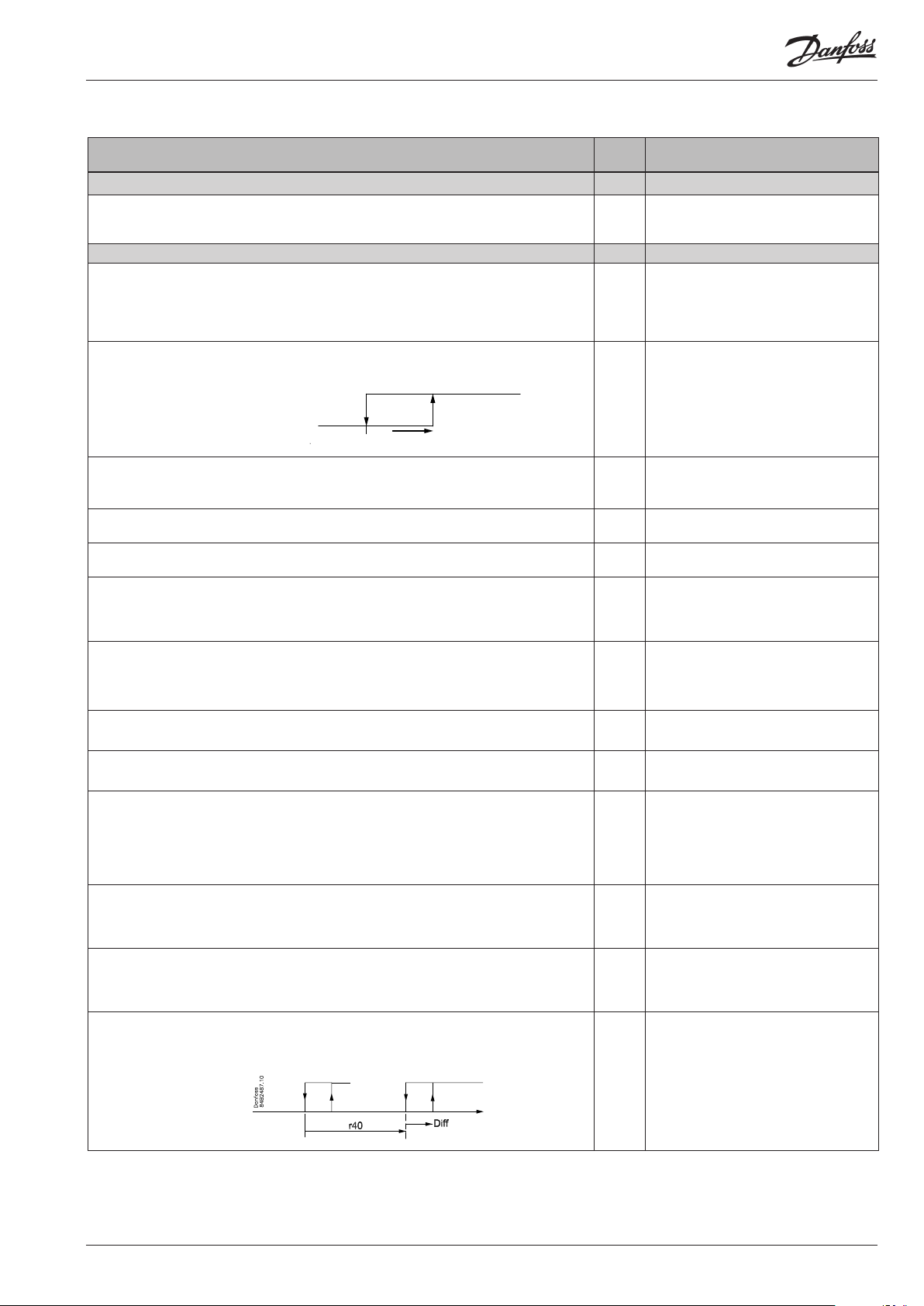
Activation of reference displacement
When the function is changed to ON the thermostat dierential will be increased by
the value in r40. Activation can also take place via input DI1 or DI2 (dened in o02 or
o37).
r39 Th. oset

8 Manual RS8EE202 © Danfoss 08-2010 EKC 202D
Value of reference displacement
The thermostat reference and the alarm values are shifted the following number of
degrees when the displacement is activated. Activation can take place via r39 or input
DI
Alarm Alarm settings
The controller can give alarm in dierent situations. When there is an alarm all the
light-emitting diodes (LED) will ash on the controller front panel, and the alarm relay
will cut in.
Alarm delay (short alarm delay)
If one of the two limit values is exceeded, a timer function will commence. The alarm
will not become active until the set time delay has been passed. The time delay is set
in minutes.
Time delay for door alarm
The time delay is set in minutes.
The function is dened in o02 or in o37.
Time delay for cooling (long alarm delay)
This time delay is used during start-up, during defrost, immediately after a defrost.
There will be change-over to the normal time delay (A03) when the temperature has
dropped below the set upper alarm limit.
The time delay is set in minutes.
Upper alarm limit
Here you set when the alarm for high temperature is to start. The limit value is set in
°C (absolute value). The limit value will be raised during night operation. The value is
the same as the one set for night setback, but will only be raised if the value is positive.
The limit value will also be raised in connection with reference displacement r39.
Lower alarm limit
Here you set when the alarm for low temperature is to start. The limit value is set in °C
(absolute value).
The limit value will also be raised in connection with reference displacement r39.
Delay of a DI1 alarm
A cut-out/cut-in input will result in alarm when the time delay has been passed. The
function is dened in o02.
Delay of a DI2 alarm
A cut-out/cut-in input will result in alarm when the time delay has been passed. The
function is dened in o37
Signal to the alarm thermostat
Here you have to dene the ratio between the sensors which the alarm thermostat
has to use. S3, S4 or a combination of the two.
With setting 0% only S3 is used. With 100% only S4 is used
Compressor Compressor control
The compressor relay works in conjunction with the thermostat. When the thermostat calls for refrigeration will the compressor relay be operated.
Running times
To prevent irregular operation, values can be set for the time the compressor is to run
once it has been started. And for how long it at least has to be stopped.
The running times are not observed when defrosts start.
Min. ON-time (in minutes) c01 Min. On time
Min. OFF-time (in minutes) c02 Min. O time
Reversed relay function for D01
0: Normal function where the relay cuts in when refrigeration is demanded
1: Reversed function where the relay cuts out when refrigeration is demanded (this
wiring produces the result that there will be refrigeration if the supply voltage to the
controller fails).
The LED on the controller’s front will show whether refrigeration is in progress. Comp Relay
r40 Th. oset K
Night setbck
(start of night signal)
Forced cool.
(start of forced cooling)
With data communication the importance of the individual alarms can be
dened. Setting is carried out in the
“Alarm destinations” menu.
A03 Alarm delay
A04 DoorOpen del
A12 Pulldown del
A13 HighLim Air
A14 LowLim Air
A27 AI.Delay DI1
A28 AI.Delay DI2
A36 Alarm S4%
Reset alarm
EKC error
c30 Cmp relay NC
Here you can read the status of the
compressor relay, or you can forcecontrol the relay in the ”Manual
control” mode
Loading…
Danfoss EKC 202D — контроллер температуры используется для регулирования температуры холодильных установок и холодильных камер в магазинах и холодильных складах. Контроллер EKC 202D имеет 2 датчика температуры, которые располагаются в потоке холодного воздуха за испарителем и в потоке теплого воздуха непосредственно перед испарителем. Включение и отключение рабочих функций выполняется с помощью 4 реле в зависимости от способа применения контроллера: охлаждение (компрессор или реле), вентиляторы, оттайка, кантовый подогрев, сигнал аварии, освещение.
Документация
Купить
| Напряжение питания | 230 В перем. тока +10/-15 %, 2,5 ВА, 50/60 Гц | |
| Датчики | Pt 1000 (1000 Ом/0°С) PTC (1000 Ом/25°С) или NTC — M2020 (5000 Ом/25°С) |
|
| Точность | Диапазон измерения | −60 … +99°C |
| Контроллер | ±1 К ниже −35°С ±0,5 К от −35 до +25°С ±1 К выше +25°С |
|
| Датчик Pt 1000 | ±0.3 K при 0 °C ±0.005 K на каждый градус |
|
| Дисплей | Светодиод, трёхзначный | |
| Внешний дисплей | EKA 163A / EKA 164A | |
| Цифровые входы | Сигнал от контактных функций Требования к контактам: позолоченные Длина кабеля не более 15 м При большей длине кабеля используйте дополнительные реле |
|
| Электрический кабель | Многожильный кабель сечением не более 1,5 мм2 Макс. 1 мм2 для датчиков и цифровых входов |
|
| Реле | DO1. Реле охлаждения | 8 (6) A и (5 FLA, 30 LRA) |
| DO2. Реле оттайки | 8 (6) A и (5 FLA, 30 LRA) | |
| DO3. Реле вентилятора | 6 (3) A и (3 FLA, 18 LRA) | |
| DO4. Реле аварийной сигнализации | 4 (1) A, мин. 100 мА | |
| Передача данных | EKC 202: через устанавливаемую карту | |
| Окружающая температура | 0 … +55°C во время работы −40 … +70°C во время транспортировки | |
| Влажность 20—80 %, без конденсата | ||
| Вибрации не допускаются | ||
| Корпус | IIP 65 лицевой панели. Кнопки и уплотнение встроены спереди. | |
| Резервное питание для часов | 4 часа | |
| Разрешения | EU Low Voltage Directive and EMC demands re CE-marking complied with LVD tested acc. EN 60730-1 og EN 60730-2-9, A1, A2 EMC tested acc. EN50082-1 og EN 60730-2-9, A2 |
Датчики
К контроллеру можно подсоединить до двух датчиков термостата. Способ подключения зависит от назначения контроллера.
Датчик перед испарителем — этот способ размещения датчика, в основном, используется для регулирования температуры в помещении.
Датчик после испарителя — этот способ размещения датчика, в основном, используется при регулировании охлаждения, когда существует опасность подачи слишком холодного воздуха на продукты.
Датчики до и после испарителя — такой способ установки датчиков дает возможность успешно приспособить термостат, аварийный термостат и дисплей к соответствующему применению.
Сигнал для термостата, аварийного термостата и дисплея задается как взвешенное значение двух температур, 50 % которого составят одинаковую величину от обоих датчиков. Сигнал для термостата, аварийного термостата и дисплея может быть настроен независимо друг от друга.
Датчик оттайки — наиболее точные показания температуры испарителя поступают от датчика оттайки, установленного непосредственно на испарителе. Эти показания используются для функции оттайки, делая этот процесс наиболее коротким и энергетически выгодным. Если датчик оттайки не используется, оттайка может быть прекращена по времени или по сигналу от датчика S4.
Изменение уставки температуры
Например, для импульсного оборудования, используемого для различных групп продуктов. Здесь уставка температуры легко изменяется с помощью сигнала, поступающего на цифровой вход. Этот сигнал изменяет нормальную уставку термостата на заданную величину. В то же время соответственно изменяются аварийные пределы.
Цифровые входы
Контроллер имеет 2 цифровых входа, которые можно использовать для следующих функций:
— уборка
— отключение устройства
— функция двери с аварией
— запуск оттайки
— координированная оттайка
— переключение между двумя температурными уставками
— изменение положения контактов через сеть передачи данных.

Introduction
Application
• The controller is used for temperature control refrigeration
appliances in supermarkets.
• With many predefined applications one unit will offer you
several options. Flexibility has been planned both for new
installations and for service in the refrigeration trade.
Principle
The controller contains a temperature control where the signal
can be received from one or two temperature sensors.
The thermostat sensors are either placed in the cold air flow after
the evaporator, in the warm air flow just before the evaporator,
or both. A setting will determine how great an influence the two
signals are to have on the control.
A measurement of the defrost temperature can be obtained
directly through the use of an S5 sensor or indirectly through
the use of the S4 measurement. Four relays will cut the required
functions in and out — the application determines which.
The options are the following:
• Refrigeration (compressor or relay)
• Fan
• Defrost
• Rail heat
• Alarm
• Light
The different applications are described on page 6.
Advantages
• Several applications in the same unit
• The controller has integrated refrigeration-technical functions,
so that it can replace a whole collection of thermostats and
timers
• Buttons and seal imbedded in the front
• Easy to remount data communication
• Two temperature references
• Digital inputs for various functions
• Clock function with super cap backup
Contents
Introduction …………………………………………………………………………………………. 2
Operation ……………………………………………………………………………………………… 3
Applications …………………………………………………………………………………………. 6
Survey of functions ……………………………………………………………………………… 7
Operation …………………………………………………………………………………………….16
2
Manual RS8EE202 © Danfoss 08-2010
Menu survey ………………………………………………………………………………………..17
Override ……………………………………………………………………………………………….19
Ordering ………………………………………………………………………………………………19
Connections ………………………………………………………………………………………..20
Data ………………………………………………………………………………………………………21
EKC 202D