
SERVICE MANUAL
For U.S.A. , Canada model
Ver. 1
MODEL
AVR-2106/886
AV SURROUND RECEIVER
注 意
サービスをおこなう前に、このサービスマニュアルを
必ずお読みください。本機は、火災、感電、けがなど
に対する安全性を確保するために、さまざまな配慮を
おこなっており、また法的には「電気用品安全法」に
もとづき、所定の許可を得て製造されております。
従ってサービスをおこなう際は、これらの安全性が維
持されるよう、このサービスマニュアルに記載されて
いる注意事項を必ずお守りください。
●
For purposes of improvement, specifications and
design are subject to change without notice.
●
Please use this service manual with referring to the
operating instructions without fail.
●
Some illustrations using in this service manual are
slightly different from the actual set.
Denon Brand Company, D&M Holdings Inc.
●
●
●
●
TOKYO, JAPAN
本機の仕様は性能改良のため、予告なく変更すること
があります。
補修用性能部品の保有期間は、製造打切後8年です。
修理の際は、必ず取扱説明書を参照の上、作業を行っ
てください。
本文中に使用しているイラストは、説明の都合上現物
と多少異なる場合があります。
X0255V.01 DE/CDM 0508
AVR-2106/886
SAFETY PRECAUTIONS
The following check should be performed for the continued protection of the customer and service technician.
LEAKAGE CURRENT CHECK
Before returning the unit to the customer, make sure you make either (1) a leakage current check or (2) a line to chassis
resistance check. If the leakage current exceeds 0.5 milliamps, or if the resistance from chassis to either side of the
power cord is less than 460 kohms, the unit is defective.
500V
1M
(1)
(2)
(1)
(2)
2
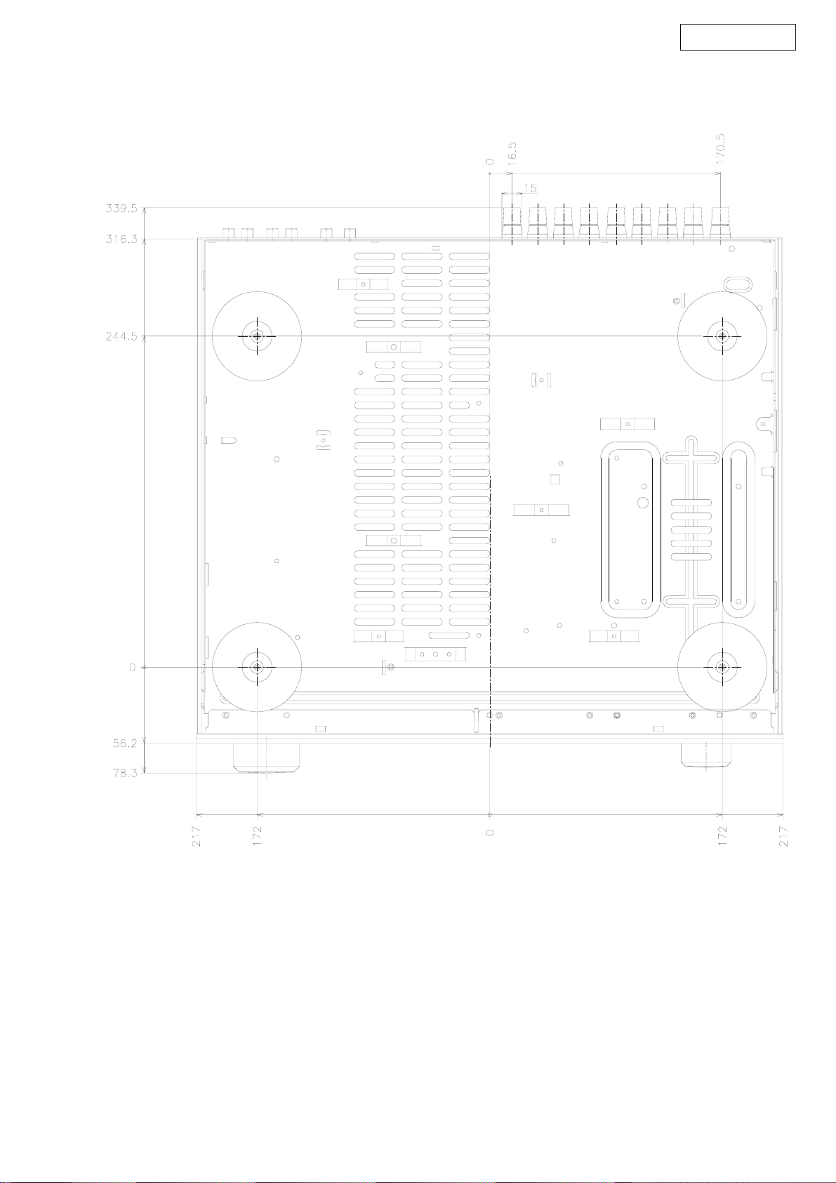
DIMENSION
AVR-2106/886
3

AVR-2106/886
CAUTION IN SERVICING
Initializing AV SURROUND RECEIVER
AV SURROUND RECEIVER initialization should be performed
when the µcom, peripheral parts of µcom, and Digital P.W.B. are
replaced.
1. Switch off the unit.
2. Hold the following SPEAKERS-A button and SPEAKERS-B
button, and switch on the unit.
3. Check that the entire display is flashing with an interval of
about 1 second, and release your fingers from the 2 buttons
and the microprocessor will be initialized.
Note:・If step 3 does not work, start over from step 1.
・ All user settings will be lost and this factory setting will
be recovered when this initialization mode.
So make sure to memorize your setting for restoring
after the initialization.
サービス時の注意事項
AVサラウンドアンプの初期化について
マイコンやマイコン周辺部品、Digital 基板等を交換した場合
は、AV サラウンドアンプの初期化を行って下さい。
1. オン/オフボタンを OFF にします。
2. SPEAKERS-A ボタンと SPEAKERS-B ボタンを同時に押しな
がら、オン/オフボタンを押して ON にします。
3. ディスプレイ表示が約 1秒間隔で点滅するのを確認後、2
つのボタンから指を離します。
*マイコンが初期化されます。
注意 :・上記 3 の状態にならない場合は、もう一度操作 1 か
らやり直してください。
・初期化を行うとお客様が設定した内容が工場出荷状
態に戻りますので、あらかじめ設定内容を控えてお
き初期化後再設定してください。
4
AVR-2106/886
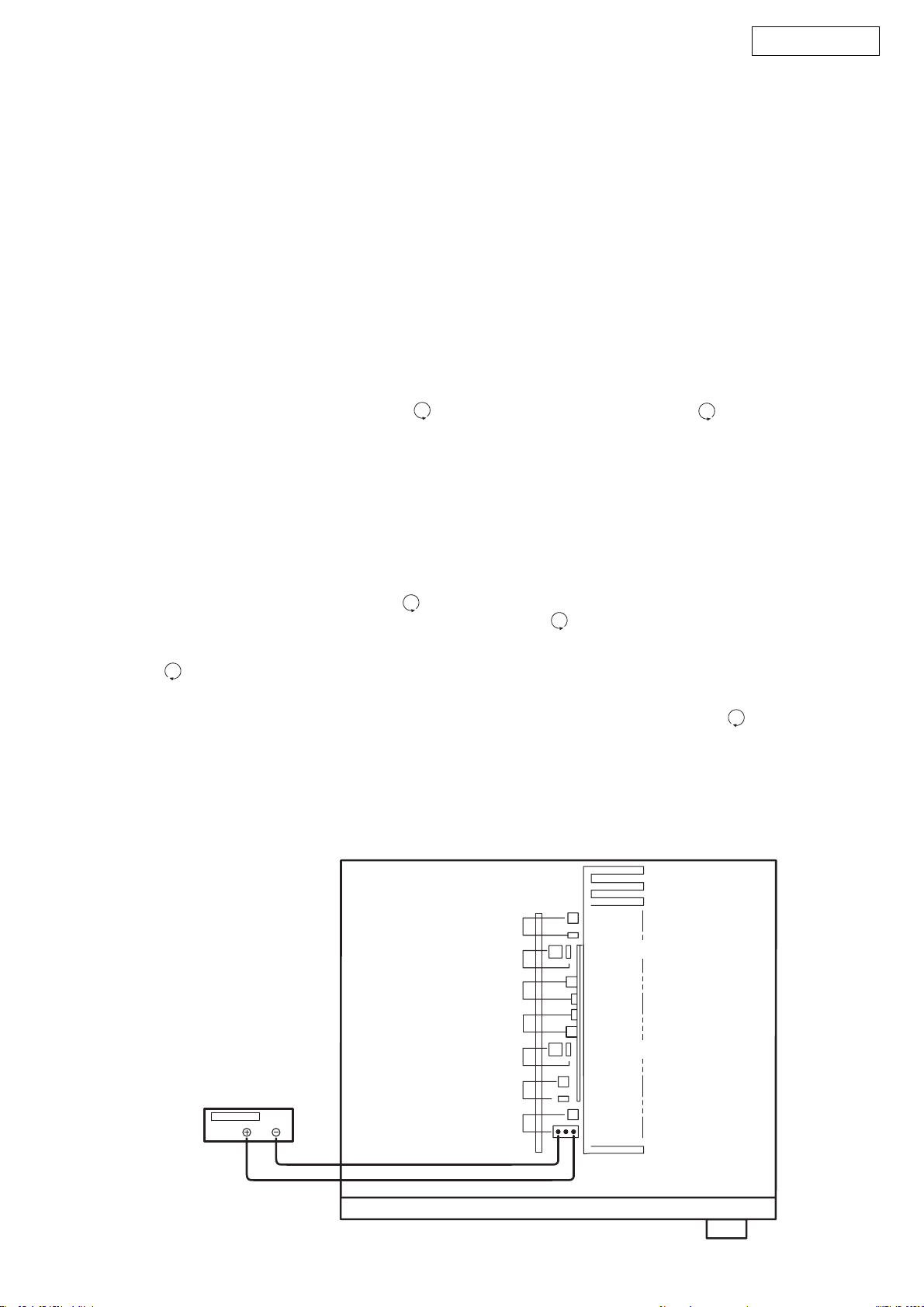
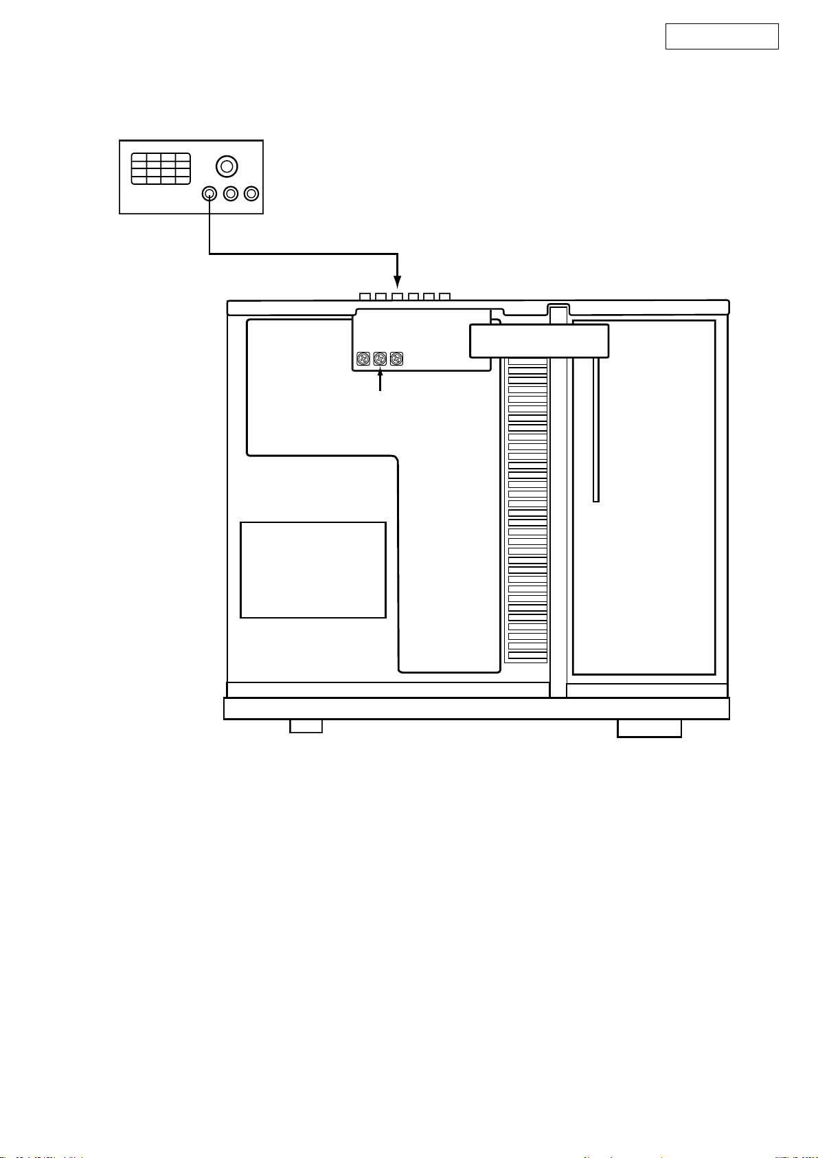
ADJUSTMENT
Audio Section
Idling Current
Required measurement equipment: DC Voltmeter
1. Preparation
(1) Avoid direct blow from an air conditioner or an electric
fan, and adjust the unit at normal room temperature 15 °C
~ 30 °C (59 °F ~ 86 °F).
(2) Presetting
• POWER (Power source switch) OFF
• SPEAKER (Speaker terminal) No load
(Do not connect speaker, dummy resistor, etc.)
2. Adjustment
(1) Remove top cover and set VR101, VR102, VR103,
VR104, VR105, on Amp. Unit, VR106,107 on SURR.BACK ch Amp. Unit at fully counterclockwise ( ) position.
(2) Connect DC Voltmeter to test points (FRONT-Lch:
TP104, FRONT-Rch: TP105, CENTER ch: TP103, SURROUND-Lch: TP101, SURROUND-Rch: TP102, SURROUND-BACK Lch: TP106, SURROUND-BACK Rch:
TP107).
(3) Connect power cord to AC Line, and turn power switch
«ON».
(4) Presetting.
MASTER VOLUME : «—» counterclockwise ( min.)
MODE : 7CH STEREO
FUNCTION : CD
(5) Within 2 minutes after the power on, turn VR101 clock-
wise ( ) to adjust the TEST POINT voltage to 1.5 mV
± 0.5 mV DC.
(6) After 10 minutes from the preset above, turn VR101 to
set the voltage to 2.5 mV ± 0.5 mV DC.
(7) Adjust the Variable Resistors of other channels in the
same way.
調整
オーディオセクション
アイドリング電流の調整
調整に必要な測定器 : DCVoltmeter
1. 準備
(1) セットをクーラ、扇風機のそばなど風通しの良い場所
を避け、通常の使用状態に置きます。セットの周囲温
度は 15〜30 ℃、湿度は常湿とします。
(2) プリセット
・電源スイッチ OFF
・スピーカ端子 無負荷
( スピーカ・ダミー抵抗器などを接続しない。)
2. 調整
(1) 上カバーをはずし、パワーアンプ基板の VR101,VR102,
VR103,VR104,VR105 及び SURR.-BACK アンプ基板の
VR106,107 を反時計方向 ( )に回し切った状態に
セットします。
(2) テストポイント (FRONT-Lch:TP104,FRONT-Rch:
TP105,CENTERch:TP103,SURROUND-Lch:TP101,
SURROUND-Rch:TP102,SURROUND-BACKLch:TP106,
SURROUND-BACKRch:TP107) に DCVoltmeterを接続
します。
(3) 電源コードを AC100V(95〜105Vの範囲でも可)に接
続し、電源スイッチを «ON»にします。
(4) ON後、次のようにセットします。
・MASTERVOLUME(音量調節つまみ)→反時計方向
( )に回す、最小の状態にする。
・SPEAKER(スピーカ端子)→無負荷(スピーカ、
ダミー抵抗器などを接続しない。)
MODE:7CHSTEREO
FUNCTION:CD
(5) 2分以内に VR101を時計方向 ( ) に回しテストポイ
ントの電圧を次のように調整します。
1.5mV ±0.5mVDC
(6) 予備調整から 10分後 VR101を回し、次のように電圧を
設定します。
2.5mV± 0.5mVDC
(7) 同じ方法で各チャネルの可変抵抗を調整します。
DC Voltmeter
F Lch
S Lch
S Back Rch
S Back Lch
C ch
S Rch
F Rch
5
VR104
TP104
VR101,TP101
VR107
TP107
TP106
VR106
VR103,TP103
VR102
TP102
VR105
TP105

AVR-2106/886
Video Section (For U.S.A., Canada)
Component Video Level Adjustment
Required measurement equipment etc.: Oscilloscope, DVD
VIDEO PLAYER (ex: DVD-1500)
Test disc: DVD T-S01
1. Preparation
(1) Avoid direct blow from an air conditioner or an electric
fan, and adjust the unit at normal room temperature 15 °C
~ 30 °C (59 °F ~ 86 °F).
(2) Playback the color-bar 75% of the Test Disc (Title 12) us-
ing the DVD Video Player, and check that Y and C levels
of the S terminal output are within the specified output
levels.
If they are out of the specified levels, adjust with the variable resister inside of the unit.
(3) Presetting
• POWER (Power source switch) OFF
• SPEAKER (Speaker terminal) No load
(Do not connect speaker, dummy resistor, etc.)
• DVD (Video terminal) No input
2. Adjustment
(1) Remove top cover and set VR608, VR609, VR610, on C-
S VIDEO2 Unit at fully counterclockwise ( ).
(2) Connect a pin-plug terminated with 75-ohms to Y (Cb, Cr)
of the Component Video Monitor Output, and hook up the
Oscilloscope’s probe to both ends of the pin-plug.
(3) Connect S terminal output of the DVD Player with the
DVD input terminal of the Receiver.
(4) Connect power cord to AC Line, and turn power switch
«ON».
(5) Presetting.
• FUNCTION: DVD
• Playback the color-bar 75% of the Test Disc (Title 12)
(6) Turn VR610 clockwise ( ) to adjust the COMPONENT
Video Y voltage (except H. Sync) to 714 ± 50 mVp-p. (Refer to Fig. 1)
(7) Adjust the Variable Resistors of Cr: VR609 and Cb:
VR608 in the same way. (Refer to Fig. 2, 3)
Cb,Cr: 486 ± 50 mVp-p. (U.S.A. & Canada model)
ビデオセクション
コンポーネントビデオレベルの調整
調整に必要な測定器 : Oscilloscope,DVDVIDEOPLAYER
( 例 :DVD-1500)
テストディスク : DVDT-S01
1. 準備
(1) セットをクーラ、扇風機のそばなど風通しの良い場所
を避け、通常の使用状態に置きます。セットの周囲温
度は 15〜30 ℃、湿度は常湿とします。
(2) DVDVIDEOPLAYER でテストディスクのカラーバー
75%(Title12) を再生し、S 端子出力 Y、C レベルが正規
の出力レベルであることを確認する。正規の出力レベ
ルでない場合は、セット内部の可変抵抗器で調整して
ください。
(3) プリセット
・電源スイッチ OFF
・スピーカ端子 無負荷
( スピーカ・ダミー抵抗器などを接続しない。)
・DVD 入力端子 無入力
2. 調整
(1) 上カバーをはずし、C-SVIDEO2 ユニットの VR608,
VR609,VR610 を反時計方向 ( )に回し切った状態に
セットします。
(2) コンポーネントビデオモニターアウトの Y(Cb,Cr) に
75Ω で終端したピンプラグを接続し、その両端を
Oscilloscope のプローブでつまみます。
(3) DVDVIDEOPLAYER の S 端子出力を本機の DVD 入力端
子に接続します。
(4) 電源コードを電源コンセントに接続し、電源スイッチ
を «ON»にします。
(5) ON後、次のようにセットします。
・本機の FUNCTION を DVD にする。
・テストディスクのカラーバー 75%(Title12) を再生す
る。
(6) VR610を時計方向 ( ) に回しコンポーネントビデオ
Y(H.Sync を除く ) の電圧を調整します。(Fig.1 参照 )
714mV ±50mVp-p
(7) 同じ方法で Cr:VR609、Cb:VR608 の可変抵抗器を調整
します。(fig.2、3 参照 )
Cb,Cr:525± 50mVp-p(Japanmodel)
6
Oscilloscope
Y
VR609
AVR-2106/886
MONITOR OUT
(Y,Cb,Cr)
CbCr
VR608VR610
Video Section
7
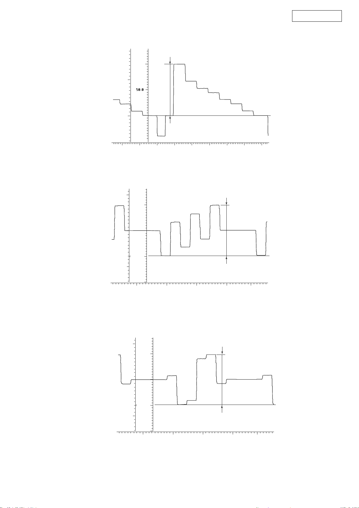
AVR-2106/886
Volts
IRE:FLT
100.0
0.5
0.0
0.5
-20.0 -10.0 0.0
Volts
0.5
IRE:FLT
50.0
Y-Signal
714±50mV
p-p
10.0
20.0 30.0
Fig.1 Component Video Y signal
40.0 50.0 60.0
486±50mV (U.S.A. & Canada model)
p-p
0.0
-0.5
Volts
0.5
0.0
0.0
-50.0
0.0
IRE:FLT
50.0
0.0
-50.0
20.0
Fig.2 Cb signal
40.0
60.0
486±50mV (U.S.A. & Canada model)
80.0
p-p
-0.5
0.0
20.0
Fig.3 Cr signal
8
40.0
60.0
80.0
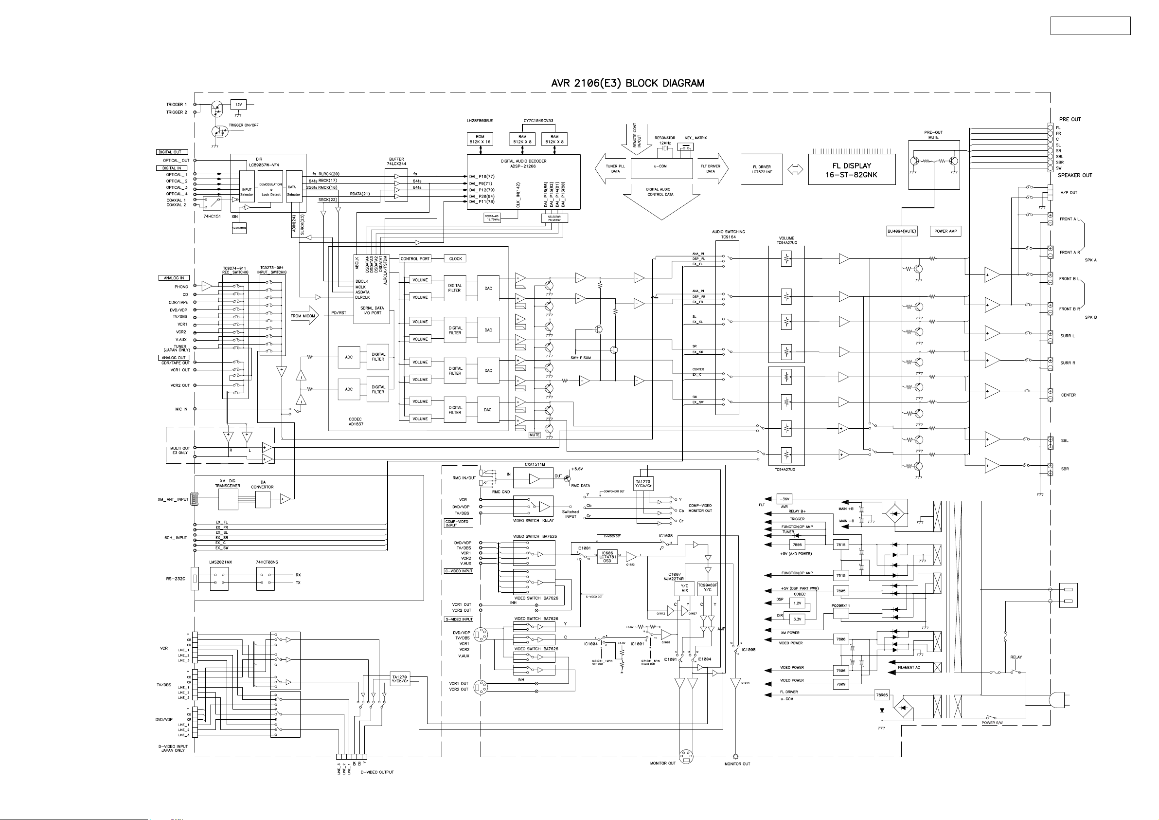
BLOCK DIAGRAM
AVR-2106/886
9
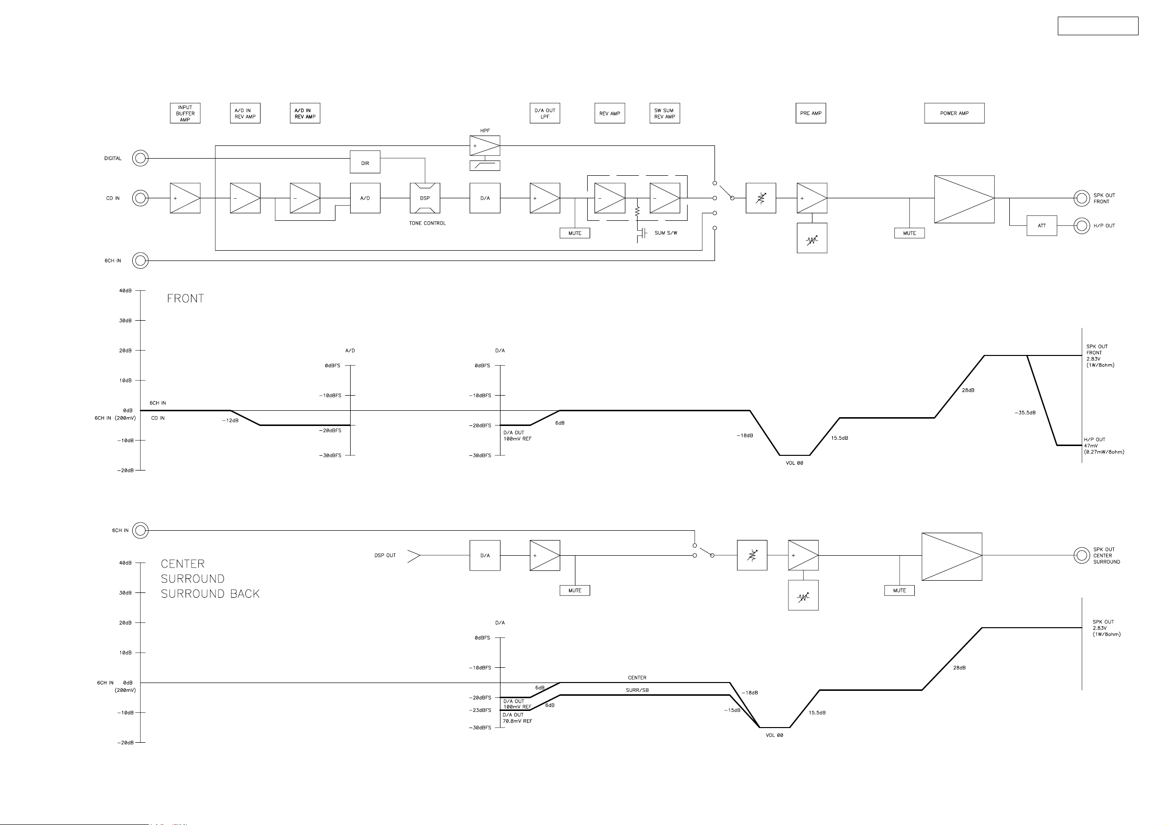
LEVEL DIAGRAMS (1/2)
AVR-2106/886
10
LEVEL DIAGRAMS (2/2)
AVR-2106/886
11
SEMICONDUCTORS
Only major semiconductors are shown, general semiconductors etc. are omitted to list.
主な半導体を記載しています。汎用の半導体は記載を省略しています。
1. IC’s
M30622MGP (IC201)
)
)
)
3
/D
4
(/D
4
/A
4
P2
4
/D
5
(/D
5
/A
5
P2
5
/D
6
(/D
6
/A
6
P2
)
6
/D
7
(/D
7
/A
7
P2
Vss
)
7
(/-/D
8
/A
0
P3
Vcc
9
10
11
12
/A
/A
/A
/A
1
2
3
4
P3
P3
P3
P3
)
)
)
0
1
2
/D
/D
/D
/-)
1
2
3
0
/INT5
/INT4
/INT3
10
8
11
12
9
/D
/D
0
1
P1
P1
13
/D
/D
/D
/D
2
3
4
5
P1
P1
P1
P1
(/D
(/D
(/D
(/D
15
14
1
2
3
0
/D
/D
/A
/A
/A
/A
7
6
1
2
3
0
P1
P1
P2
P2
P2
P2
AVR-2106/886
15
16
17
18
13
14
/A
/A
/A
7
5
6
P3
P3
P3
19
/A
/A
/A
/A
0
1
2
3
P4
P4
P4
P4
P107/AN7/KI
P106/AN6/KI
P105/AN5/KI
P104/AN4/KI
P103/AN
P102/AN
P101/AN
P100/AN
P97/AD
P07/D
P06/D
P05/D
P04/D
P03/D
P02/D
P01/D
P00/D
AV
V
AVcc
TRG/SIN
REF
/W
OUT
/TA2
4
P7
/V
IN
/TA1
2
/RTS
2
/CTS
3
P7
515253545556575859606162636465666768697071727374757677787980
IN
/V
OUT
/TB5
IN
/TA1
2
/CLK
2
/SCL/TA0
2
P7
/RxD
1
P7
50
49
48
47
46
45
44
43
42
41
40
39
38
37
36
35
34
33
32
31
OUT
/SDA/TA0
2
D
X
/T
0
P7
7
81
6
82
5
83
4
84
3
85
2
86
1
87
0
88
3
89
2
90
1
91
92
0
93
3
94
2
95
1
SS
96
97
0
98
99
00
1
4
1 2 3 4 5 6 7 8 9 101112131415161718192021222324252627282930
0
2
4
IN
OUT
/TB4
1
/DA
4
/ANEX0/CLK4
P9
/ANEX1/S
5
6
P9
P9
IN
/TB3
0
/DA
3
P9
3
OUT
/S
IN
/TB2
2
P9
3
IN
/S
IN
/TB1
1
P9
BYTE
/CLK3
IN
/TB0
0
P9
CIN
/X
7
CNVss
P8
COUT
/X
6
P8
OUT
X
RESET
IN
SS
X
V
1
CC
V
/NMI
/INT
/INT
5
4
3
P8
P8
P8
/INT
2
P8
/U
IN
/TA4
1
P8
/U
OUT
/TA4
0
P8
IN
/TA3
7
P7
OUT
/TA3
6
P7
/W
IN
/TA2
5
P7
P44/CS0
P45/CS1
P46/CS2
P47/CS3
P50/WRL/WR
P51/WRH/BHE
2
/RD
P5
P53/BCLK
P54/HLDA
P55/HOLD
P56/ALE
P57/RDY/CLK
P60/CTS0/RTS
P61/CLK
P62/RxD
P6
3/TXD0
P64/CTS1/RTS1/CTS0/CLKS
P65/CLK
P66/RxD
P67/TXD
OUT
0
0
0
1
1
1
1
M30622MGP Terminal Function
PIN
No.
1 SW_SUM O SW SUMMING CONTROL
2 4094CLK O BU4094(IC551~3) CLOCK
3 2090_CLK(VIDEO)/F O BU2090F(IC1003,1005) CLOCK
4 2090_DATA/LC74781_DATA/G O BU2090F(IC1003) DATA/LC74781(IC1006) DATA
5 2090_DATA2/LC74781_CLK/VIDEO_MUTE O BU2090F(IC1005) DATA/LC74781(IC1006) SCLK
6 REMOCON I REMOCON SIGNAL DATA INPUT
7 1837_SDIN I AD1837(IC808) SERIAL DATA INPUT
8 BYTE GND —
9 CNVSS — UP GRADE PIN
10 2090_DATA/4094_DATA O BU4094(IC551~3) DATA /BU2090F(IC302) DATA
11 FLD_RST/4094_EN O LC75721NE(IC301) RESET CONTROL/BU4094(IC551~3) OUTPUT ENABLE
12 RESET I u-COM RESET SIGNAL INPUT
13 XOUT O OSILATOR CONNECTION
14 Vss GND GND
15 XIN I OSILATOR CONNECTION
16 Vcc1(+5V) 5V POWER 5V
17 PWR_DOWN I POWER DOWN CONTROL INPUT
18 FLAG0 I EPROM chip select control for DSP
19 89057_INT I LC89057(IC807) INT SIGNAL INPUT
PIN NAME I/O FUNCTION
12
AVR-2106/886
PIN
No.
20 PROTECTION I PROTECTION SIGNAL INPUT
21 FLD/2090_CLK O BU2090F(IC302) CLOCK/ LC75721NE(IC301) CLOCK
22 FLD_DATA O LC75721NE(IC301) DATA
23 FLD_CE O LC75721NE(IC301) CHIP ENABLE
24 9273_STB O TC9273-004(IC705) STB
25 9273/9162_DATA O TC9273-004(IC705) DATA/TC9164(IC203T) DATA
26 9273/9164_CLK O TC9273-004(IC705)CLOCK /TC9164(IC203T) CLOCK
27 9164_STB O TC9164(IC203T) STB
28 9274_STB O TC9274-011(IC701) STB
29 90A69/1270_CKL O TC90A69(IC1009) SCL/TA1270BF(IC1154) SCL
30 90A69/1270_DATA I/O TC90A69(IC1009) SDA/TA1270BF(IC1154) SDA
31 RS232C_TX O RS232C SIGNAL OUTPUT
32 RS232C_RX I RS232C SIGNAL INPUT
33 XM-COMMAND O XM-COMMAND SIGNAL
34 XM-REQ O XM-REQ SIGNAL
35 XM-MIXMO I XM-MIXMO SIGNAL
36 XM-MIXMI O MX-MIXMI SIGNAL
37 PLL_CLK O TUNER PLL CLOCK
38 PLL_CE O TUNER PLL CHIP ENABEL
39 TUNED I TUNED SIGNAL INPUT
40 STEREO I STEREO SIGNAL INPUT
41 RS232C_UP I CONNECT TO RESET
42 VOL_UP I MASTER VOLUME ENCODER(VEC301)
43 VOL_DOWN I MASTER VOLUME ENCODER(VEC301)
44 SEL_UP I SELECT ENCONDER(VEC302)
45 SEL_DOWN I SELECT ENCONDER(VEC302)
46 RS232C_UP I UP GRADE PIN
47 POWER_D/W I POWER DOWN CONTROL INPUT
48 PLL_DATA_OUT O TUNER PLL_DATA OUTPUT
49 ERR_MUTE O ERROR MUTE
50 BSE O DIGITAL SIGNAL MUTE
51 89057_EMPHA I LC89057(IC807) EMPHA SIGNAL INPUT
52 SHARC_SDIN I SHARC(IC804) SD INPUT
53 89057_SDIN I LC89057(IC807) D0 SIGNAL INPUT
54 EPPROM_RST O FLASH ROM(IC805) RESET
55 89057_RST O LC89057(IC807) RESET
56 SHARC_CE O SHARC(IC804) CHIP ENABEL
57 SHARC_SDOUT O CHARC(IC804) SD OUT
58 89057_CE O LC89057(IC807) CHIP ENABLE
59 89057/1837_SDOUT O LC89057(IC807) D1 SIGNAL / AD1837(IC808) CIN SIGNAL
60 89057/1837_SCLK O LC89057(IC807) CL / AD1837(IC808) CCLK
61 1837_RST O AD1837(IC808) RESET SIGNAL OUT (TO IC821)
62 Vcc2(+5V) 5V POWER 5V
63 SHARC_SCLK O SHARC(IC804) SPICLK
64 Vss GND —
65 SHARC_RST O SHARC(IC804) RESET SIGNAL
66 1837_CE O AD1837(IC808) CLATCH
67 FLAG3 I Special flag for ROM updata
68 FLAG2 I DSP operation check flag
69 FLAG1 I NON USE
70 H/P_DET I HEAD PHONE DETECT
71 FUNC_UP I FUNCTION ENCODER (VEC303)
72 FUNC_DOWN I FUNCTION ENCODER (VEC303)
73 PLL_DATA_IN I TUNER PLL DATA INPUT
74 XM-4094STB O BU4094(IC208X) STB
PIN NAME I/O FUNCTION
13
AVR-2106/886
PIN
No.
75 MIC_DET I MIC DETECT INPUT
76 POWER_RELAY O POWER RELAY CONTROL
77 STBY_LED(RED) O STBY LED RED CONTROL
78 VCR_MUTE/94A27_STB O TA94A27(IC201T,202T) STB
79 3811/94A27_CLK O TA94A27(IC201T,202T) CLK/BD3811 CLK
80 3811/94A27_DATA O TA94A27(IC201T,202T) DATA/DB3811 DATA
81 MUTE_POWER O MUTE CONTROL
82 4094_STB(RLY) O BU4094(IC551) STB
83 4094_STB(RLY_MUTE) O BU4094(IC553) STB
84 4094_STB(MUTE) O BU4094(IC552) STB
85 S-MON_DET I S-MONITOR DETECT
86 COMP_VIDEO_DET I COMPONENT SIGNAL INPUT DETECT
87 C_VIDEO_DET I CONPOSIT SIGNAL INPUT DETECT
88 S_VIDEO_DET I S VIDEO SIGNAL INPUT DETECT
89 RS232C_SW O
90 KEY_IN1 I KEY1 SIGNAL INPUT
91 KEY_IN2 I KEY2 SIGNAL INPUT
92 KEY_IN3 I KEY3 SIGNAL INPUT
93 XM-DACMDI I PCM1791ADBR(IC205X) MDI SIGNAL
94 STEP_OPTION I AREA OPTION SELECT
95 XM-DACMC O PCM1791ADBR(IC205X) MC SIGNAL
96 AVss GND GND
97 XM-DACMS O PCM1791ADBR(IC205X) MS SIGNAL
98 VREF 5V VREF
99 AVcc 5V POWER 5V
100 74781_CE/J I LC74781(IC1006) CS
PIN NAME I/O FUNCTION
SN74HAHCT08(IC203) POWER CONTROL/ LMS202IMX(IC202) POWER
CONTROL
PQ20RX11J00H (IC103X)
14
ADSP-21266SKSTZ-2B (IC804)
AVR-2106/886
144
1
PIN 1 INDICATOR
109
108
TOP VIEW
36
37
73
72
ADSP-21266SKSTZ-2B Terminal Function
LQFP
Pin Name
V
DDINT
Pin # Pin Name
1V
DDINT
CLKCFG0 2 GND 38 GND 74 V
CLKCFG1 3 RD 39 V
BOOTCFG0 4 ALE 40 GND 76 V
LQFP
Pin # Pin Name
37 V
DDEXT
DDINT
LQFP
Pin # Pin Name
73 GND 109
DDINT
75 GND 111
DDINT
BOOTCFG1 5 AD15 41 DAI_P10 (SD2B) 77 GND 113
GND 6 AD14 42 DAI_P11 (SD3A) 78 V
V
DDEXT
7 AD13 43 DAI_P12 (SD3B) 79 GND 115
GND 8 GND 44 DAI_P13 (SCLK23) 80 V
V
DDINT
9V
DDEXT
45 DAI_P14 (SFS23) 81 GND 117
GND 10 AD12 46 DAI_P15 (SD4A) 82 V
V
DDINT
11 V
DDINT
47 V
DDINT
83 GND 119
GND 12 GND 48 GND 84 V
V
DDINT
13 AD11 49 GND 85 RESET 121
DDINT
DDEXT
DDINT
DDINT
GND 14 AD10 50 DAI_P16 (SD4B) 86 SPIDS 122
FLAG0 15 AD9 51 DAI_P17 (SD5A) 87 GND 123
FLAG1 16 AD8 52 DAI_P18 (SD5B) 88 V
DDINT
AD7 17 DAI_P1 (SD0A) 53 DAI_P19 (SCLK45) 89 SPICLK 125
GND 18 V
V
DDINT
19 GND 55 GND 91 MOSI 127
DDINT
54 V
DDINT
90 MISO 126
GND 20 DAI_P2 (SD0B) 56 GND 92 GND 128
V
DDEXT
GND 22 GND 58 DAI_P20 (SFS45) 94 V
V
DDINT
AD6 24 V
21 DAI_P3 (SCLK0) 57 V
23 V
DDEXT
DDINT
59 GND 95 A
60 V
DDEXT
DDINT
93 V
96 A
DDINT
DDEXT
VDD
VSS
AD5 25 GND 61 FLAG2 97 GND 133
AD4 26 DAI_P4 (SFS0) 62 FLAG3 98 CLKOUT 134
V
DDINT
27 DAI_P5 (SD1A) 63 V
DDINT
99 EMU 135
GND 28 DAI_P6 (SD1B) 64 GND 100 TDO 136
AD3 29 DAI_P7 (SCLK1) 65 V
AD2 30 V
V
DDEXT
31 GND 67 V
GND 32 V
DDINT
DDINT
66 GND 102 TRST 138
68 GND 104 TMS 140
AD1 33 GND 69 V
DDINT
DDINT
DDINT
101 TDI 137
103 TCK 139
105 GND 141
AD0 34 DAI_P8 (SFS1) 70 GND 106 CLKIN 142
WR 35 DAI_P9 (SD2A) 71 V
V
DDINT
36 V
DDINT
72 V
DDINT
DDINT
107 XTAL 143
108 V
DDEXT
LQFP
Pin #
110
112
114
116
118
120
124
129
130
131
132
144
15
AD1837 (IC808)
AVR-2106/886
DSDATA3
DSDATA2
AGND
DGND
DSDATA1
39
38
37
36
35
34
33
32
31
30
29
28
27
NC
OUTL3
MCLKASDATAABCLKALRCLKODVDDDVDD DVDD
PD/RST M/S AVDD AVDD
CLOCK
DIGITAL
FILTER
DIGITAL
FILTER
DIGITAL
FILTER
DIGITAL
FILTER
DescriptionPin No.
DVDD
DBCLK
DLRCLK
M/S
AGND
OUTR4
NC
OUTL4
NC
AGND
AVDD
OUTR3
NC
V
Σ—∆
DAC
Σ—∆
DAC
Σ—∆
DAC
Σ—∆
DAC
REF
OUTL1
OUTR1
OUTL2
OUTR2
OUTL3
OUTR3
OUTL4
OUTR4
FILTD
FILTR
DLRCLK
DBCLK
DSDATA1
DSDATA2
DSDATA3
DSDATA4
ADCLP
ADCLN
ADCRP
ADCRN
AD1837 Terminal Function
Pin Name
CLATCH
PD/RST
OUTR1
Σ—∆
ADC
Σ—∆
ADC
AD1837
Input/
Output
DVDD
CIN
AGND
NC
OUTL1
NC
AGND
AVDD
NC
OUTL2
DGND
CCLK
COUT
ASDATA
ODVDD
MCLK
ALRCLK
ABCLK
50 494847 46 45 44 43 42 41 40
51
52
1
2
3
4
5
6
7
8
9
10
11
12
13
14 15 16 17 18 19 20 21 22 23 24 25 26
NC
SERIAL DATA
I/O PORT
DIGITAL
FILTER
DIGITAL
FILTER
AGND
OUTR2
TOP VIEW
AVDD
FILTD
FILTR
DGND AGND AGND AGND AGNDDGND
DSDATA4
ADCLP
ADCLN
ADCRN
CINCLATCHCCLK COUT
CONTROL PORT
VOLUME
VOLUME
VOLUME
VOLUME
VOLUME
VOLUME
VOLUME
VOLUME
ADCRP
1,39 DVDD Digital Power Supply. Connect to digital 5V supply.
2 CLATCH I Latch Input for Control Data
33 CIN I Serial Control Input
4 PD/RST I Power-Down/Reset
5,10,16,24,30,35 AGND Analog Ground
6,12,25,31 NC Not connected
7,13,26,32 OUTLx O DACx Left Channel Output
8,14,27,33 NC Not connected
9,15,28,34 OUTRx O DACx Right Channel Output
11,19,29 AVDD Analog Power Supply. Connect to analog 5V supply.
17 FILTD Filter Capacitor Connection. Recommend 10µF/100nF.
18 FILTR Reference Filter Capacitor Connection. Recommended 10µF/100nF.
20 ADCLN I ADC Left Channel Negative Input
21 ADCLP I ADC Left Channel Positive Input
22 ADCRN I ADC Right Channel Negative Input
23 ADCRP I ADC Right Channel Positive Input
36 M/S I ADC Master/Slave Select
37 DLRCLK I/O DAC LR Clock
38 DBCLK I/O DAC Bit Clock
40,52 DGND Digital Ground
41-44 DSDATAx I DACx Input Data (Left and Right Supply)
45 ABCLK I/O ADC Bit Clock
46 ALRCLK I/O ADC LR Clock
47 MCLK I Master Clock Input
48 ADVDD Digital Output Driver Power Supply
49 ASDATA O ADC Serial Data Output
50 COUT O Output for Control Data
51 CCLK I Control Clock Input for Control Data
16
LC89057W (IC807)
AVR-2106/886
RXOUT
RX0
RX1
RX2
RX3
RX4
RX5/VI
RX6/UI
LPF
TMCK/PIO0
TBCK/PIO1
TLRCK/PIO2
TDATA/PIO3
TXO/PIOEN
10
13
44
45
46
47
48
1
2
3
4
5
8
9
EMPHA/UO33AUDIO/VO35INT40CL39CE38DI
32
Clock
Selector
27
Microcontroller
Input
Selector
Modulation
or
Parallel Port
29
XIN
C bit, U bit
Demodulation
&
Lock Detect
PLL
28
XOUT
XMCK34CKST
I/F
Data
Selector
I/N
XMODE
41
37
36
21
24
16
17
20
22
23
DO
RERR
RD ATA
SDIN
RMCK
RBCK
RLRCK
SBCK
SLRCK
36 RERR1RXOUT
35 INT2RX0
34 CKST3RX1
TOP VIEW
33 AUDIO/VO4RX2
32 EMPHA/UO5RX3
31 DGND6DGND
30 DVDD7DVDD
29 XIN8RX4
28 XOUT9RX5/VI
27 XMCK10RX6/UI
26 DVDD11DVDD
25 DGND12DGND
24 SDIN37DO
23 SLRCK38DI
22 SBCK39CE
21 RDATA40CL
20 RLRCK41XMODE
19 DVDD42DGND
18 DGND43DVDD
17 RBCK44TMCK/PIO0
16 RMCK45TBCK/PIO1
15 AGND46TLRCK/PIO2
14 AVDD47TDATA/PIO3
13 LPF48TXO/PIOEN
LC89057W Terminal Function
Pin
No.
1 RXOUT O Input bi-phase select data output terminal
2 RX0 I TTL compatible digital data input terminal
3 RX1 I Coaxial compatible amp built-in digital data input terminal
4 RX2 I TTL compatible digital data input terminal
5 RX3 I TTL compatible digital data input terminal
6 DGND — Digital GND
7 DVDD — Digital power
8 RX4 I TTL compatible digital data input terminal
9 RX5/VI I TTL compatible digital data/Validity flag input terminal for modulation
10 RX6/UI I TTL compatible digital data/User data input terminal for modulation
11 DVDD — Digital power for PLL
12 DGND — Digital GND for PLL
13 LPF O PLL loop filter connecting terminal
14 AVDD — Analog power for PLL
15 AGND — Analog GND for PLL
16 RMCK O RMCK clock output terminal (256fs, 512fs, XIN, VCO)
17 RBCK O/I RBCK clock in/output terminal (64fs)
18 DGND — Digital GND
19 DVDD — Digital power
20 RLRCK O/I RLRCK clock in/output terminal (fs)
21 RDATA O Serial audio data output terminal
22 SBCK O SBCK clock output terminal (32fs, 64fs, 128fs)
23 SLRCK O SLRCK clock output terminal (fs/2, fs, 2fs)
24 SDIN I Serial audio data input terminal
25 DGND — Digital GND
26 DVDD — Digital power
27 XMCK O Osc. amp output terminal
Pin Name
I/O
Function
17
AVR-2106/886
Pin
No.
Pin Name I/O
Function
28 XOUT O X’tal osc. connecting output terminal
29 XIN I X’tal osc. connection, external clock input terminal (24.576MHz or 12.288MHz)
30 DVDD — Digital power
31 DGND — Digital GND
32 EMPHA/UO I/O Emphasis information/U-data output/Chip address setting terminal
33 AUDIO/VO I/O Non-PCM detect/V-flag output/ Chip address setting terminal
34 CKST I/O Clock switch transition period output/Demodulation master or slave function switching terminal
35 INT I/O Interrupt output for µcom (Interrupt factor selectable)/Modulation or general I/O switching terminal
36 RERR O PLL lock error, data error flag output
37 DO O µcom I/F, read out data output terminal (3-state)
38 DI I µcom I/F, write data input terminal
39 CE I µcom I/F, chip enable input terminal
40 CL I µcom I/F, clock input terminal
41 XMODE I System reset input terminal
42 DGND — Digital GND
43 DVDD — Digital power
44 TMCK/PIO0 I/O 256fs system clock input for modulation/General I/O in/output terminal
45 TBCK/PIO1 I/O 64fs bit clock input for modulation/General I/O in/output terminal
46 TLRCK/PIO2 I/O fs clock input for modulation/General I/O in/output terminal
47 TDATA/PIO3 I/O Serial audio data input for modulation/General I/O in/output terminal
48 TXO/PIOEN O/I Modulation data output/ General I/O enable input terminal
* For latch-up countermeasure, perform each power supply ON/OFF in the same timing.
TC94A27UG (IC201T,202T)
L‑MVR‑AGNDA2
NC
34
L‑MVR‑AGNDARE
35
L‑MVR‑AGNDARE
36
L‑MVR‑AGNDB1
37
L‑MVR‑AGNDB2
38
L‑MVR‑OUTB
39
L‑TVR‑OUTB
40
L‑TVR‑1NB
41
L‑TVR‑REFB
42
L‑MVR‑1NB
43
NC
44
L‑TVR‑OUTA
L‑TVR‑REPA
31
3233
L‑TVR‑INA
Latch
Latch
Latch
Latch Latch
Test&
autoclearcircuit
30
29
L‑MVR‑INA
Decodercircuit
Timing
generating
circuit
NC
26
27
28
R‑MVR‑INA
LatchLatch
Decodercircuit
24bitshiftregister
Levelshiftcircuit
25
R‑TVR‑REF
24
R‑TVR‑INA
Latch
LatchLatch Latch
R‑MVR‑OUTA
23
R‑TVR‑OUTA
Latch
NC
22
R‑MVR‑AGNDA2
21
R‑MVR‑AGNDA1
20
R‑MVR‑AGNDB1
19
R‑MVR‑AGNDB2
18
R‑MVR‑OUTB
17
R‑TVR‑OUTB
16
R‑TVR‑1NB
15
R‑TVR‑REFB
14
R‑MVR‑1NB
13
NC
12
TEST
VDD
CS1
CS2
MUTEM
18
GND
MUTE
CK
87654321
9
STB
DATA
VSS
1110
AS7C34096A-10TCN (IC806,817)
Top View
1
44
NC
43
2
3
4
5
6
7
8
9
10
11
12
13
14
15
16
17
18
19
20
21
22
NC
42
NC
A
41
18
A
40
17
A
39
16
A
38
15
37
OE
I/O
36
7
I/O
35
6
V
34
SS
V
33
CC
I/O
32
5
I/O
31
4
A
30
14
A
29
13
A
28
12
A
27
11
A
26
10
25
NC
24
NC
23
NC
I/O
I/O
V
V
I/O
I/O
WE
NC
NC
CE
NC
NC
A
0
A
1
A
2
A
3
A
4
0
1
CC
SS
2
3
A
5
A
6
A
7
A
8
A
9
WE
OE
AVR-2106/886
I/O
I/O
I/O
I/O
I/O
I/O
I/O
I/O
0
1
2
3
4
5
6
7
INPUT BUFFER
A
0
A
1
A
2
A
3
A
4
A
5
A
6
A
7
A
A
A
ROW DECODER
8
9
10
512K x 8
ARRAY
COLUMN
DECODER
11
12
A
A13A
14
ACEA
SENSE AMPS
POWER
DOWN
15
16
17
18
A
A
A
TC90A69F (IC1009) NJM2274R (IC1007)
COUT
27
28
DAC
INTERPOLATION
1
2
VRT
BIAS VB1
26
(8fsc)
3
VSS1
25
DAC
CORING
PEAKING
4
VDD1
YOUT
VB2
24
LPF
5
VSS2
TESTI1
PD
23
22
PLL DET 1/2VCO
1/8
Ped.
CLIP
ADC
6
7
VRB
FIL
21
8fsc 4fsc
KILLER
Sync. Clamp
8
YCIN
VSS4
20
TEST
VDD4
DELAY
CNR
C-N.C
9
KILLER
19
10
FSC
TESTOUT
MODE1
18
17
16
CORING V-ENHANCER
LINE
LINE
MEMORY
MEMORY
DYNAMIC COMB FILTER
11
12
13
VSS3
VDD3
TESTI2
SDA
15
IIC BUS
14
VDD2
SCL
TESTI3
1Yin
Disc.
Cin
8 Bias
1
2
3
4
Power Save CTL
Clamp
TOP
VIEW
C Mute CTL
8
7
6
5
Vref
Vcc
GND
2
+
+
2
750
ohm
7
7
LC75721 (IC301) BU2090 (IC302,1003,1005)
G7 G8G9
G10
48 33
49
DI
CL
CE
RES
DD
V
OSCI
OSCO
Vss
TEST
FL
V
G1
G2
G3
G4
G5
G6
64
AM 1
AM 2
AM 3
AM 4
G11
AA8/G12
AA7/G13
AA6/G14
AA5/G15
AA4/G16
AA3
AA2
AA1
AM35
AM34
AM33
161
AM 5
AM 6
AM 7
AM 8
AM 9
AM 10
AM 11
AM 12
AM 13
AM 14
AM 15
AM 16
LC75721E Terminal Function
Symbol
32
17
AM 17
AM 18
AM 19
AM 20
AM 21
AM 22
AM 23
AM 24
AM 25
AM 26
AM 27
AM 28
AM 29
AM 30
AM 31
AM 32
V
DD
Vss
V
FL
DI
CL
CE
OSCI
OSCO
RES
AM1~AM35
AA1~AA3
AA4/G16
AA5/G15
AA6/G14
AA7/G13
AA8/G12
Power terminal +5V
Power terminal GND
Power terminal FL drive
Serial data transfer terminal
DI: Data
CL: Clock
CE: Chip enable
External CR connecting terminal
System reset terminal
Anode output terminal
Anode/Grid output terminal
Function
VSS
DATA
CLOCK
LCK
1
CONTROL CIRCUIT
2
12-bi t SHIFT REGI STER
3
4
5
6
7
8
9
12- bit STRAGE REGI STER
OUTPUT BUFF ER (OPE N DRAI N)
Q0
Q1
Q2
Q4
G1~G11 Grid output terminal
TEST LSI test terminal
18
VDD
OE
17
16
Q11
Q10
15
Q9
14
Q8
13
12
Q7
Q6
11Q3
Q5
10
3 Vout
Vsag4
19
TA1270BF (IC1154) TC9274N-011 (IC701)
C
DAC1
Y INPUT
DAC Vcc (5V)
C Vcc (5V)
UV/CbCr SW
fsc OUTPUT
1HDL CONT
SECAM CONT
B-Y/Cb OUTPUT
R-Y/Cr OUTPUT
DAC2
39
40
41
42
43
44
45
46
47
48
DAC237Y OUTPUT36GND35DAC
38
Y OFFSETSWDAC
DAC1
PEDESTAL
CLAMP
Y DL
fsc
1H DL
CONTROL
SECAM
CONTROL
CbCr / UV
SW
VCXO
1
2
X’tal
4.43MHz
TEST34SDA33SCL32Ys
TEST
SUB-
Y DL
CONTRAST
SW
fsc
TRAP
SYSTEM
LPF / fsc
TRAP
BPF H. AFC H C / D
APC
SUB-COLOR
3
4
X’tal
APC
M-X’tal
3.58MHz
I2C BUS
CONTROL
5
C GND
CW
MATRIX
P / N ID
SW
TOF
ACC
6
OUTPUT
CHROMA
(TH=0.7V
HI; 1IN/LOW; 2IN)31R-Y1
Ys
TINT
DEMO
CHROMA
BLK
V SEP
7
V-SE P
SYNC
SEP
OFFSET
SW
8
INPUT
SYNC.
INPUT30B-Y1
PEDESTAL
CLAMP
9
SYNC.
OUTPUT
INPUT29Y1
YUV RGB
NOSE
DET
10
AFC
MATRIX
FILTER
INPUT28I
2
11
SYNC.
GND
GND
R-Y2
27
SW
32fH
VCO
12
32fh VCO
INPUT26B-Y2
PEDESTAL
CLAMP
13
VD
V C / D
INPUT25Y2
INPUT
HI: 20h/LOW: 24h
SW
CP / HP
IN
SCP
14
HD
OUTPUT
OUTPUT
24
23
22
21
20
19
18
17
16
15
SW GND
ADRS SW
R-Y/R
OUTPUT
B-Y/B
OUTPUT
Y/G
OUTPUT
SW
Vcc (9V)
SYNC
Vcc (9V)
CP/HP
INPUT
Dig GND
SCP
OUTPUT
S1S2S3S4S5S6S7S8S9
41
40
V
DD
42
V
SS
1
2
345678 9 10 111213 14
S1S2S3S4S5S6S7S8S9
36
3839
37
35
18 bit Latch Circuit (Rch)
S10
32
34
33
(Lch) Same as Rch
S10
AVR-2106/886
S11
S12
S13
S14
S15
S16
S17
S18
26
27
16 171819
S14
S15
S16
24
25
23
STB
22
DATA
21
CK
Level Shift + Shift Register Circuit
20
GND
S17
S18
29
28
3031
15
S11
S12
S13
TC9273N-004 (IC705)
Vss
1
S1
2
S2
3
4
S3
S4
5
6
S5
7
S6
S7
8
9
S8
10
S9
11
S10
S1
S2
S3
S4
S5
S6
S7
S8
S9
S10
12
13
GND
14
CK
DATA
TC9164 (IC203T)
V
SS
1
2
L-S
1
3
L-S
2
L-S
3
4
L-S
4
5
6
L-COM
1
L-S
5
7
L-S
6
8
L-COM
2
9
10
L-S
7
L-S
11
8
12
L-COM
3
13
ST
GND
14 15
STB
TC9273N Terminal Function
V
DD
28
27
26
25
24
23
22
21
Symbol Name
Pin No
1
13
28
2~12
S1~S10
12~27
14
15
DATA
16
Vss
GND
V
DD
CK
STB
+Power Terminal
Digital Ground
+Power Terminal
I/O Terminal
Clock Input
Data Input
Dual Power Use:VDD = 8.0~17 V Single Power Use:VDD = 8.0~18V
Input terminal of analog switch.
Clock input for data transfer.
Serial input for switch setting.
Strobe InputStrobe input for data writing.Strobe Input
20
19
18
17
16
15
GND
V
DD
14
28
Latch Circuit
28
27
26
25
24
23
22
21
20
19
18
17
16
V
DD
R-S
1
R-S
2
R-S
3
R-S
4
R-COM1
R-S
5
R-S
6
R-COM2
R-S
7
R-S
8
R-COM3
DATA
CK
L-S
L-S
L-S
L-S
L-COM
L-S
L-S
L-COM
L-S
L-S
L-COM
ST
V
SS
1
1
2
3
2
3
4
4
5
1
6
5
7
8
6
2
9
10
7
11
8
12
3
Level Shifter
Latch Circuit
13
Shift Register
Function
GND=0V
Vss=-8.0~-17V
Level Shifter
27
26
25
24
23
22
21
20
19
18
17
16
15
R-S
1
R-S
2
R-S
3
R-S
4
R-COM
R-S
5
R-S
6
R-COM
R-COM
R-S
7
R-S
8
DATA
CK
GND=0V
Low level
Border Input
Terminal
1
2
3
20
LC74781 (IC1006)
1
V
SS1
2
Xtal
IN
3
Xtal
OUT
4
CTRL1
5
BLANK
6
OSC
IN
7
OSC
OUT
8
CHARA
9
CS
10
SCLK
11
SIN
12
V
DD2
AVR-2106/886
LC74781 Trminal Function
24
V
DD1
23
RST
22
CTRL3
21
CTRL2
20
SEP
IN
19
SEP
OUT
18
SEP
C
17
SYN
IN
16
V
DD1
15
CV
IN
14
NC
13
CV
OUT
Pin No. Symbol Name
1 VSS1 GND
2 Xtal IN Xtal oscillation
3 Xtal OUT Xtal oscillation
4 CTRL1 Xtal oscillation input switching
5 BLANK Blank output
6 OSC IN LC oscillation
7 OSC OUT LC oscillation
8 CHARA Character output
9 CS Enable input
10 SCLK Clock input
11 SIN Data input
12 VDD2 Power
13 CV OUT VIDEO signal output
14 NC
15 CV IN VIDEO signal input
16 VDD1 Power
17 SYN IN Sync. separate circuit input
18 SEP C Sync. separate circuit bias voltage
19 SEP OUT Complex sync. signal output
20 SEP IN Vertical sync. signal input
21 CTRL2 NTSC/PAL-M switching input
22 CTRL3 SEP IN input control
23 RST Reset input
24 VDD1 Power (+5V)
CS
SIN
SCLK
RST
VDD1
VSS1
VDD2
CHARA
OSCIN
OSCOUT
SYNIN
SEPC
SEPOUT
SEPIN
CTRL3
9
Serial
11
parallel
converter
10
23
24
1
12
8
Horizontal
6
character
7
register
17
Horizontal
character
18
register
19
20
22
size
size
8-bits
latch
+
command
decoder
Horizontal
character
Horizontal
character
size
register
size
register
Horizontal
character
size
register
Horizontal
size
counter
Vertical
character
size
register
Vertical
size
counter
Timing generator
4
CTRL1
Horizontal
display
position
register
Horizontal
dot
counter
Blinking
and inversion
control
register
Character
control
counter
Vertical
display
position
register
Vertical
dot
counter
Blinking
and inversion
control
register
Line
control
counter
Synchronization
signal generator
21 2 3 5 15 13
XtalIN XtalOUT BLANK CVIN CVOUTCTRL2
Blinking
and inversion
control
register
Blinking
and inversion
control
circuit
Character output control
Background control
Video output control
Display
control
register
RAM
write
adress
counter
Decoder
Display
RAM
Decoder
Font
RAM
Shift
register
21
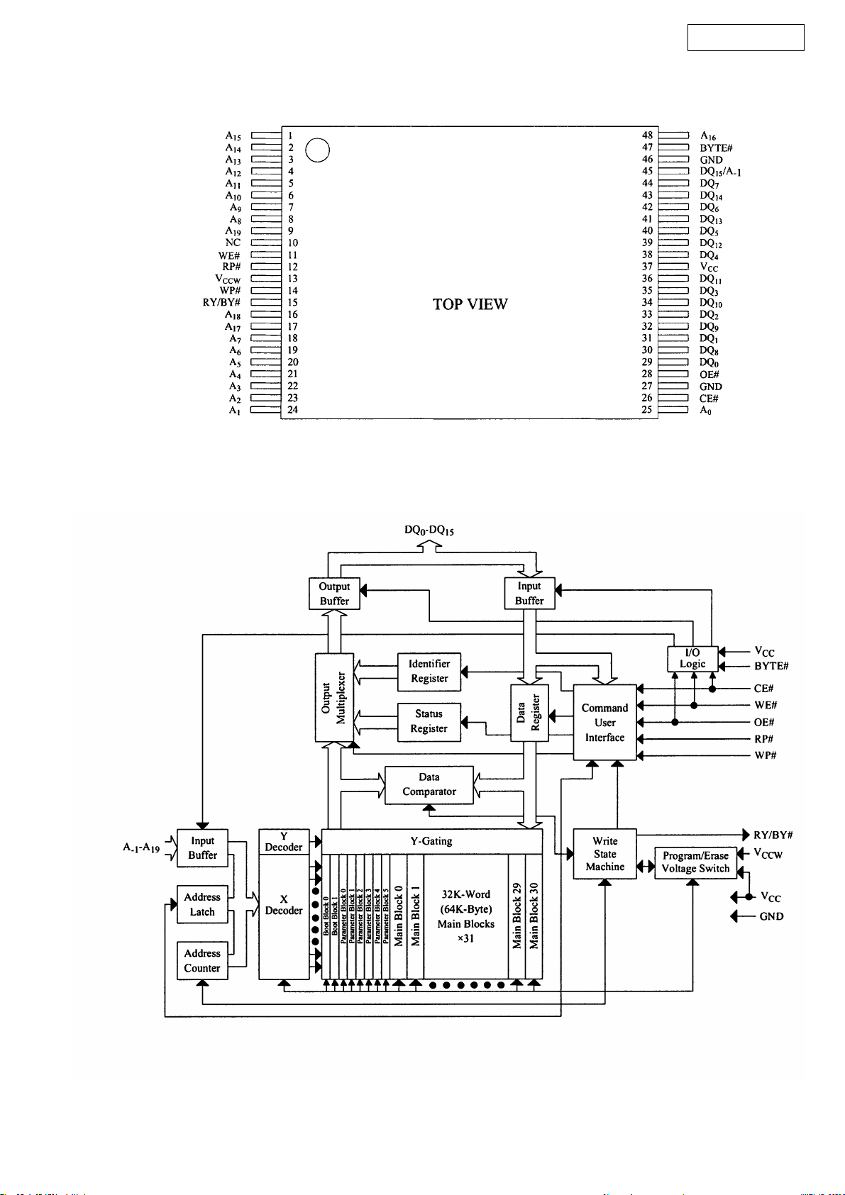
LH28F800BJE (IC805)
LH28F160BJE (IC805)
AVR-2106/886
LH28F160BJE Block Diagram
22
BA7626 (IC1000,1002,1150~1153)
AVR-2106/886
Monitor OUT
ABE
MONITOR OUT
LL* IN 1 LL*
H L * IN 2 H L * IN 2 H L *
GND
IN5
GND
IN4
CTL E
IN3
CTL D
1
2
3
6dB
LOGIC
4
5
6
7
6dB
LOGIC
8
16
15
14
13
11
10
12
9
IN1
CTL A
V OUT1
Vcc
IN2
CTL B
V OUT2
CTL C
C D E V OUT 1 C D E V OUT 2
LL* IN 1
L H * IN 3 L H * IN 3 L H * IN 3
H H L IN 4 H H L IN 4 H H L IN 4
HHH IN 5 HHH IN 5 HHH IN 5
Note 1: * mark means that feasible for either H or L.
Note 2: Each input terminal is provided with sink chip clamp (BA7625).
Each input terminal takes 20kohm at the end (BA7626).
BU4052BCF (IC601D,602D) MM74HC4053MX (IC1001,1004,1008)
Common
Y
INH
V
Vss
Y
Y
Y
Y
EE
4
2
3
1
1
2
3
4
5
6
7
8
TOP VIEW
Y
0
X
Y
2
Y
X
OUT/IN
Y
3
OUT/IN
X
Y
1
X
INH
V
EE
B
V
DD
16
2
X
2
15
X
14
1
1
Common
X
13
0
3
A
X
X
0
12
X
3
11
10
A
9
B
X:Don’t Care
FUNCTION TABLE
INH
A B ON SWITCH
L
LLX
L
HL
L
LH
L
HH
H
XX
Y
00
XY
11
XY
22
XY
33
NONE
Y1
Y0
Z1
Z0
Enable
EE
V
GND
Truth Table
1
2
3
4
Z
5
6
7
8
16
Vcc
15
Y
14
X1
13
X
12
X0
11
C
10
A
9
B
Control Inputs
Select
Enable C B A
L L L L Z0 Y0 X0
L L L H Z0 Y0 X1
L L H L Z0 Y1 X0
L L H H Z0 Y1 X1
L H L L Z1 Y0 X0
L H L H Z1 Y0 X1
L H H L Z1 Y1 X0
L H H H Z1 Y1 X1
H X X X None
X = Don’t Care
ONSwitches
SN74LVC139A (IC820) 74LVX157 (IC816)
FUNCTION TABLE
1G
1A
1B
1Y0
1Y1
1Y2
1Y3
GND
(each decoder/demultiplexer)
1
16
V
2
3
4
5
6
7
8
CC
15
2G
14
2A
13
2B
12
2Y0
11
2Y1
10
2Y2
9
2Y3
INPUTS
SELECT
G
G
B A Y3 Y2 Y1 Y0
L L L H H H L
L L HHHLH
L H LHLHH
L H HLHHH
H X X H H H H
OUTPUTS
OUTPUTS
SE
LECT
1A
2A
2Y
GND
1B
1Y
2B
SEL
16
15
14
13
12
11
10
Vcc
ST
4A
4B
4Y
3A
3B
9
3Y
1
2
3
4
5
5
6
7
8
SN74LV573APW (IC818,819) SN74LV14APW (IC829)
Vcc
OE
D0
D1
D2
D3
D4
D5
D6
D7
GND
1
2
3
4
5
6
7
8
9
10
20
Q0
19
Q1
18
Q2
17
Q3
16
Q4
15
Q5
14
13
Q6
12
Q7
11
LE
OE
11
E
1
D1 D2
D0
234
D
D
D
Q
L
Q0 Q1
L
Q
Q
L
L
1819
17
Q2
D3 D4 D5 D6
567
D
D
Q
Q
L
L
16
Q3
89
D
Q
L
Q4 Q5 Q6 Q7
D7
D
D
Q
Q
L
L
12131415
GND
1
1A
2
1Y
2A
3
4
2Y
5
3A
3Y
6
7
Vcc
14
13
6A
6Y
12
5A
11
5Y
10
9
4A
4Y
8
23
PCM1791ADBR (IC205X)
AVR-2106/886
LRCK
BCK
DATA
MUTE
SCKI
RST
V
DD
DGND
AGNDF
V R
CC
AGNDR
V R-
OUT
V R+
OUT
V
COM
1
2
3
4
5
6
7
8
9
10
11
12
13
14
28
27
26
25
24
23
22
21
20
19
18
17
16
15
MS
MC
MDI
MDO
RSV
ZEROL
ZEROR
V F
CC
V L
CC
AGNDL
V L-
OUT
V L+
OUT
AGNDC
V C
CC
PCM1791 Terminal Function
Pin
No.
1 LRCK I
2 BCK I Bit clock input. Connected GND for DSD mode*
3DATA I
4 MUTE I
5 SCKI I System Clock Input. BCK (64fs) clock input for DSD mode*
6 RST I Reset*
7V
8 DGND — Digital ground
9 AGNDF — Analog ground (DACFF)
10 VCCR — Analog power supply (R-channel DAC), +5.0 V
11 AGNDR — Analog ground (R-channel DAC)
12 V
13 V
14 V
15 VCCC — Analog power supply (internal bias), +5.0 V
16 AGNDC — Analog ground (internal bias)
17 V
18 V
19 AGNDL — Analog ground (L-channel DAC)
20 VCCL — Analog power supply (L-channel DAC), +5.0 V
21 VCCF — Analog power supply ( DACFF), +5.0 V
22 ZEROR O Zero flag for R-channel
23 ZEROL O Zero flag for L-channel
24 RSV — Reserved pin. It must be open.
25 MDO O Serial data output for function control register**
26 MDI I Serial data input for function control register*
27 MC I Shift clock for function control register*
28 MS I Mode control chip select and latch signal*
* Schmitt trigger input, 5V tolerant.
** Tristate output.
Pin Name
I/O
Left and right clock (f
s
) input for normal operation. WDCK clock input in external DF mode.
Connected to GND in DSD mode*
Serial audio data input for normal operation. L-channel audio data input for external DF and DSD
modes*
Analog output mute control for normal operation. R-channel audio data input for external DF and
DSD modes*
DD
OUT
R- O R-channel analog voltage output-
OUT
R+ O R-channel analog voltage output+
COM
OUT
L+ O L-channel analog voltage output+
OUT
L- O L-channel analog voltage output-
— Digital power supply, +3.3 V
— Internal bias de-coupling pin
DESCRIPTIONS
24
2. FL DISPLAY
16-ST-82GNK (FL301)
AVR-2106/886
59
TUNED
STEREO
RDS
CH
G16
TUNED
RDS
CH
G15 G13
STEREO
AUTO
Pin Assignment
AUTO
G14
REC
ZONE2
REC
ZONE2
PHONO
VCR
G12
PHONO
VCR
G11
CD
—
1
G10
CD
—
TUNER
-2-
TUNER
-2-
1
AUX
3 V.AUX
G9
3
G8
DVD /
CDR
G7
AUX
V.AUX
VDP TV
TAPE
/
G6
DVD /
CDR
G5
/
-1-
G4
VDP
TAPE
/
2
DBS
DIGITAL
G3
TV
-1-
PRO LOGICII
DIGITAL
ANALOG
G2
DBS
/
2
DIGITAL
1
G1
PRO LOGIC
DIGITAL
ANALOG
G1
S38
S14
S13
S15
S12
S9
S10
S11
S1
S6
S2
S7
S5
S3
S4
G2~G16
S3
S8
S13
S18
S23
S28
S33
S4
S9
S14
S19
S24
S29
S34
S5
S10
S15
S20
S25
S30
S35
S2
S1
S7
S6
S12
S11
S17
S16
S22
II
S21
S26
S31
S27
S32
PIN NO.
CONNECTION
PIN NO.
CONNECTION
PIN NO.
CONNECTION
12345
F1 F1
21 22
S18
NP
23 24 25
S19 S20 S21 S22 S23 S24 S25 S26 S27 S28 S29 S30 S31 S32 S33 S34 S35 S36 S37
41 42 43 44 45
S38
G16 G15 G14 G13 G12 G11 G10 G9 G8 G7 G6 G5 G4 G3 G2 G1 F2 F2
Anode & Grid Assignment
G1
G2~G16
S1
S2
S3
S4
S5
S6
S7
S8
S9
S1
S2
S3
S4
S5
S6
S7
S9
S1
S2
S3
S4
S5
S6
S7
S8
S9
6
S1 S2 S3
26
46
S10
S11
S12
S13
S14
S15
S10
S11
S12
S13
S14
S15
S16
S17
S18
DIGITAL
PRO LOGIC
7 8 9 10 11 12 13 14 15 16 17 18 19
S5 S6 S7 S8 S9 S10 S11 S12 S13 S14 S15
S4
27 28 29 30 31 32 33 34
35 36 37 38
47 48 49 50 51 52 53 54 55 56 57
G1
G2~G16
S10
S11
S12
S13
S14
S15
S16
S17
II
S18
S19
S20
S21
S22
S23
S24
S25
S26
S27
G1
G2~G16
S19
S20
S21
S22
S23
S24
S25
S26
S27
S28
S29
S30
S31
S32
S33
S34
S35
20
S16 S17
39 40
58 59
F1, F2 : Filament
G1~G16 : Grid
S1~S38 : Anode
G1
G2~G16
S28
S29
S30
S31
S32
S33
S34
S35
S36
S37
S38
G1 G2 G3 G4 G5 G6 G7 G8 G9 G10 G11 G12 G13 G14 G15
STEREO
AUTO
S38
/
—
2
DBS
TV
—
/(DVD)
VDP
TAPE
/(CDR)
1
CDR
AUXDVD
V.AUX
TUNER
—
2
—
3
CD
—
PHONO
1
VCR
REC
ZONE2
25
G16
TUNED
RDS
CH
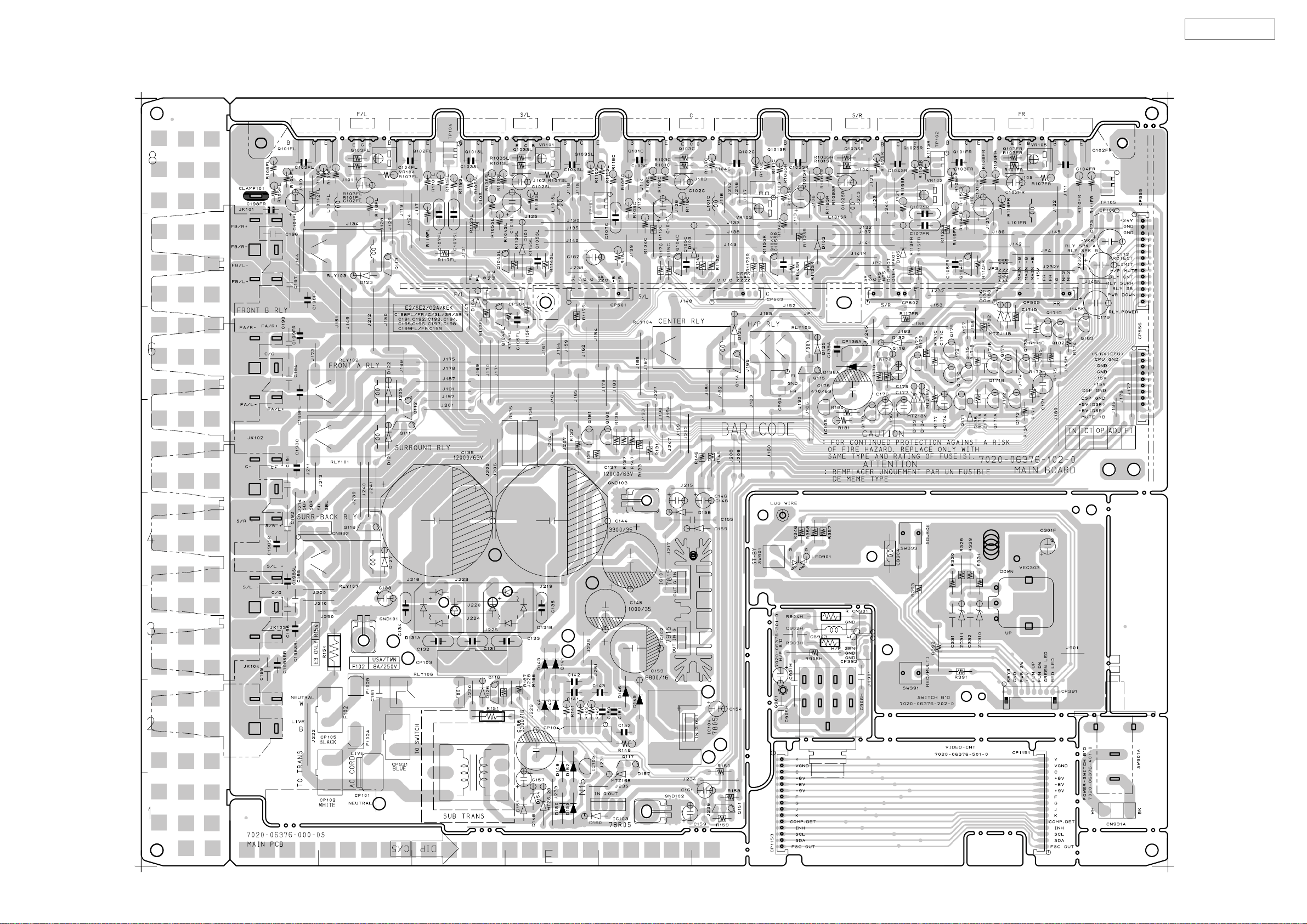
PRINTED WIRING BOARDS
MAIN P.W.B. UNIT
AVR-2106/886
26
COMPONENT SIDE
CPU P.W.B. UNIT
AVR-2106/886
27
COMPONENT SIDE
AVR-2106/886
28
FOIL SIDE
Loading…
Denon AVR-2106
AV SURROUND RECEIVER
OPERATING INSTRUCTIONS
Manual
View the manual for the Denon AVR-2106 here, for free. This user manual comes under the category receivers and has been rated by 8 people with an average of a 8.3. This manual is available in the following languages: English. Do you have a question about the Denon AVR-2106?
Ask your question here
Product Images (2)

Denon AVR-2106 specifications
Below you will find the product specifications and the manual specifications of the Denon AVR-2106.
The Denon AVR-2106 is a receiver that is designed to provide high-quality audio output for home theatre systems. With a maximum power output of 100W per channel, it is capable of delivering strong and clear sound for movies, music, and other audio content. It supports a range of audio formats, including Dolby Digital, DTS, and Dolby Pro Logic IIx, which enhances the sound quality of different types of media.
The receiver has multiple HDMI inputs, allowing users to connect a range of devices, including Blu-ray players, game consoles, and media streaming devices. It also has component video inputs, S-Video inputs, and composite video inputs to ensure compatibility with a wide range of devices. Additionally, it has a built-in AM/FM tuner, allowing users to listen to their favorite radio stations.
The Denon AVR-2106 features a user-friendly interface, with an on-screen display that can be controlled via the included remote or the front panel. It also has an auto-setup function, which calibrates the system for optimal performance based on the room size and speaker placement.
Overall, the Denon AVR-2106 is a reliable and high-performing receiver that can enhance the audio quality of any home theatre system.
General
| Brand | Denon |
| Model | AVR-2106 | AVR-2106 |
| Product | receiver |
| Language | English |
| Filetype | User manual (PDF) |
Frequently asked questions
Can’t find the answer to your question in the manual? You may find the answer to your question in the FAQs about the Denon AVR-2106 below.
Can bluetooth devices of different brands be connected to each other?
Yes, bluetooth is a universal method that allows different devices equipped with bluetooth to connect to each other.
What is bluetooth?
Bluetooth is a way of exchanging data wirelessly between electronic devices via radio waves. The distance between the two devices that exchange data can in most cases be no more than ten metres.
What is HDMI?
HDMI stands for High-Definition Multimedia Interface. An HDMI cable is used to transport audio and video signals between devices.
When is my volume too loud?
A volume above 80 decibels can be harmful to hearing. When the volume exceeds 120 decibels, direct damage can even occur. The chance of hearing damage depends on the listening frequency and duration.
How can I best clean my receiver?
A slightly damp cleaning cloth or soft, dust-free cloth works best to remove fingerprints. Dust in hard-to-reach places is best removed with compressed air.
Wat is Dolby Atmos?
Dolby Atmos is a technology that ensures that the sound is reflected from the ceiling to where you are listening. This makes it possible to create a 5.1 effect with only 1 speaker.
Is the manual of the Denon AVR-2106 available in English?
Yes, the manual of the Denon AVR-2106 is available in English .
Is your question not listed? Ask your question here
Страницы и текст этой инструкции
Инструкция — AVR-2106
Информация отображена на картинке
Информация отображена на картинке
Информация отображена на картинке
Информация отображена на картинке
Как использовать наш сайт инструкций OnlineManuals.ru
Наша цель состоит в том, чтобы предоставить вам быстрый доступ к содержанию инструкции для — AVR-2106.
С помощью онлайн просмотра, Вы можете быстро просмотреть содержимое инструкции и найти решение проблемы с — AVR-2106.
Для Вашего удобства
Если листать руководство пользователя — AVR-2106 прямо на сайте, не очень удобно для Вас, есть два возможных решения:
• Просмотр в полноэкранном режиме — легко просмотреть руководство пользователя (без загрузки его на свой компьютер), Вы можете использовать режим полноэкранного просмотра.
Для просмотра инструкции пользователя — AVR-2106 на полном экране, используйте кнопку «Открыть в Pdf-viewer».
• Загрузка на компьютер — Вы можете также скачать Инструкция — AVR-2106 на свой компьютер и сохранить его в файлах.
Многие люди предпочитают читать документы не на экране, а в печатной версии.
Возможность печати руководства пользователя также была предусмотрена на нашем сайте,
и вы можете использовать ее, нажав на иконку «печать» в Pdf-viewer.
Нет необходимости печатать все руководство — AVR-2106, можно выбрать только нужные страницы инструкции.
Русский
- Bedienungsanleitung Denon AVR-2106
- Denon AVR-2106 User Manual
- Manual Usuario Denon AVR-2106
- Mode d’emploi Denon AVR-2106
- Istruzioni Denon AVR-2106
- инструкция Denon AVR-2106
- Denon AVR-2106の取扱説明書
- Handleiding Denon AVR-2106
- Manual de uso Denon AVR-2106
Вам нужна инструкция? Мы поможем Вам ее найти и сэкономить Ваше время.
- 63 stron
- 4.39 mb
Изделие Denon AVR-2106, а также другие, которыми Вы пользуетесь ежедневно, наверняка вы получили в комплекте с инструкцией обслуживания. Из опыта наших пользователей мы знаем, что большинство из Вас не уделили этому особого внимания. Большая часть инструкций, сразу же после покупки попадает в корзину для мусора вместе с коробкой — это ошибка. Ознакомьтесь с информацией, касающейся инструкции Denon AVR-2106, которая поможет Вам в будущем сэкономить нервы и избежать головной боли.
Важная подсказка — не забывайте хотя бы раз прочитать инструкцию Denon AVR-2106
Если вы не хотите каждый раз читать информационные брошюры, касающиеся, тех или Denon AVR-2106 иных изделий, достаточно, прочитать их раз — сразу же после покупки устройства. Вы получите основное знания, касающиеся поддержания изделия Denon AVR-2106 в хорошем эксплуатационном состоянии, так, чтобы без проблем достигнуть его планируемого цикла работы. Затем инструкцию можно отложить на полку и вернуться к ней только в случае, если вы не уверены, правильно ли проводится техобслуживание изделия. Правильный уход является необходимым элементом Вашего удовольствия Denon AVR-2106.
Раз в году пересмотрите шкафчик, в котором держите инструкции для всех устройств, — выбросите те, которыми вы уже не пользуетесься. Это поможет Вам сохранять порядок в своей домашней базе инструкций обслуживания.
Summary of Contents for Denon AVR-2106
Что находится в инструкции Denon AVR-2106? Почему стоит ее прочитать?
- Гарантия и подробности, касающиеся техобслуживания изделия
Хорошей идеей будет прикрепить чек к странице инструкции. Если что-то плохое случится во время использования Denon AVR-2106, у вас будет комплект документов, необходимый для гарантийного ремонта. В этой части инструкции вы найдете информацию об авторизованных сервисных центрахDenon AVR-2106 а также, как самостоятельно правильно ухаживать за оборудованием — так, чтобы не потерять гарантийных прав. - Указания по монтажу и Setup
Не терять нервов и времени на самостоятельную попытку установки и первого запуска изделия. Воспользуйтесь рекомендациями производителя Denon AVR-2106 чтобы правильно запустить изделие, без лишнего риска повреждения оборудования. - Информация, касающаяся дополнительных запчастей (входящих в комплект а также являющихся опцией)
Пересматривая эту часть документа вы сможете проверить, доставлен ли ваш Denon AVR-2106 с полним комплектом аксессуаров. Вы также сможете узнать, какие дополнительные запчасти или аксессуары для Denon AVR-2106 Вы сможете найти и докупить к своему устройству. - Troubleshooting
Самые частые проблемы, касающиеся Denon AVR-2106 и методы их решения. Это очень полезная часть руководства по обслуживанию — она позволит Вам сэкономить много времени на поиск решений. 90% проблем с Denon AVR-2106 повторяется у многих пользователей. - Требования, касающиеся питания и энергетический класс
Информация, касающаяся количества потребляемой энергии, а также рекомендации, касающиеся установки и питания Denon AVR-2106. Прочитайте, чтобы оптимально пользоваться Denon AVR-2106 и не использовать большего количества ресурсов, нежели это необходимо для правильной работы изделия. - Специальные функции Denon AVR-2106
Здесь вы можешь узнать, как персонализировать изделие Denon AVR-2106. Вы узнаете, какие дополнительные функции могут помочь Вам удобно использовать продукт Denon AVR-2106 а также, какие функции Вашего устройства оптимальны для выполнения конкретной деятельности.
Как видите в инструкции вы найдете информацию, которая реально поможет Вам в использовании Вашего изделия. Стоит с ней ознакомиться, чтобы избежать разочарований, возникающих из более короткого, нежели предусматривалось, периода исправности изделия Denon AVR-2106. Если все же вы не хотите копить инструкции в своем доме, наш сайт поможет Вам в этом — вы должны найти у нас руководство по обслуживанию большинства из своих устройств, а также Denon AVR-2106.
Комментарии (0)
-
Страница 1
AV SURROUND RECEIVER A VR-2106 OPERA TING INSTRUCTIONS[…]
-
Страница 2
• DECLARA TION OF CONFORMITY We declare under our sole responsibility that this product, to which this declaration relates, is in conformity with the following standards: EN60065, EN55013, EN55020, EN61000-3-2 and EN61000-3-3. Following the provisions of 73/23/EEC, 89/336/EEC and 93/68/EEC Directive. CAUTION RISK OF ELECTRIC SHOCK DO NOT OPEN CAU[…]
-
Страница 3
2 System setup menu page 36 page 36 page 36 page 37 page 37 page 38 page 41 page 41, 42 page 42, 43 page 43 page 43, 44 page 8 ~11 page 38 page 38, 39 page 39 page 39 page 40 page 40[…]
-
Страница 4
1 Getting Started Contents Getting Started Accessories ··············································································2 Before using ······························································[…]
-
Страница 5
2 Getting Started Getting Started Accessories Check that the following parts are included in addition to the main unit: q Operating instructions ……………………….1 w Service station list …………………………….1 e Remote control unit (RC-1016) ……………1 r R6P/AA batteries ………………………………2 e rt u y t[…]
-
Страница 6
3 Getting Started Getting Started Operating range of the remote control unit 30° 30° Approx. 7 m • Point the remote control unit at the remote sensor on the main unit as shown in the diagram. • The remote control unit can be used from a straight distance of approximately 7 meters from the main unit, but this distance will be shorter if there […]
-
Страница 7
4 Getting Started Remote control unit For details on the functions of these parts, refer to the pages given in parentheses ( ). SURROUND buttons ·····························(17, 25) Indicator ··············(31, 33) Input source selector buttons ···············(17, 31) System buttons ···?[…]
-
Страница 8
5 Easy Setup and Operation Easy Setup and Operation Speaker connections • Connect the speaker terminals with the speakers making sure that like polarities are matched ( < with < , > with > ). Mismatching of polarities will result in weak central sound, unclear orientation of the various instruments, and the stereo image being impaired[…]
-
Страница 9
>< <> >< <> >< >< >< >< >< IN ( L ) ( R ) ( L ) ( R ) ( L ) ( R ) ( L ) ( R ) 6 Easy Setup and Operation Easy Setup and Operation 2 Connections When making connections, also refer to the operating instructions of the other components. Connection terminal for a subwoofer with built-in amplifier .[…]
-
Страница 10
7 Easy Setup and Operation Easy Setup and Operation Connecting a DVD player and monitor TV S VIDEO IN VIDEO IN Monitor TV COMPONENT VIDEO IN Y P B P R F H G •T o connect the video output from the DVD player to the A VR-2106, you only need to choose one connection type. Component video connection offers the best quality (and is required for progre[…]
-
Страница 11
8 Easy Setup and Operation Easy Setup and Operation The Auto Setup function of this unit performs an analysis of the speaker system to permit an appropriate automatic setting. Auto Setup 2 Measurement and setting details q : This sets the speaker connection, polarity , and bass reproduction ability . w : This sets the delay time from each speaker c[…]
-
Страница 12
9 Easy Setup and Operation Easy Setup and Operation Starting Auto Setup 2 Press the CURSOR D D or H H button to select “Auto Setup”, then press the ENTER button. • The “Auto Setup” screen appears. 1 Press the SETUP button. • The “System Setup” menu appears. When “S. Back” is selected, the test tone during Auto Setup will be outp[…]
-
Страница 13
Easy Setup and Operation Easy Setup and Operation 10 About error messages • These error screens may be displayed when performing Auto Setup measurement and the automatic measurements can not be completed because of the speaker arrangement, measurement environment, or other factors. Please check the following matters, reset the pertinent items, an[…]
-
Страница 14
11 Easy Setup and Operation Playing a DVD with surround sound 1 Disconnect the microphone fr om the unit. 2 Select the input source to be played. 3 Select the play (surround) mode. 4 5 Adjust the volume. Start DVD playback. Store: Store the checked measurement values. All parameters are stored. Retry: Perform the measurement again. Measurement is r[…]
-
Страница 15
12 Connecting Other Sources Connecting Other Sources With the A VR-2106, the Video signal and the S-V ideo signal which were inputted are mutually converted. The flow of the video signals. This unit’ s input terminals This unit’ s output terminals (S-Video terminal) (Video terminal) The video conversion function (Component video terminals) (Com[…]
-
Страница 16
Connecting Other Sources Connecting Other Sources 13 Connecting a TV/DBS tuner F G A TV S VIDEO OUT R L AUDIO OUT VIDEO OUT COMPONENT VIDEO OUT Y P B P R OPTICAL OUT R L R L H D • For best picture quality choose the component video connection to your TV or DBS tuner . S-Video and composite video inputs are also provided if your TV or DBS tuner do[…]
-
Страница 17
Connecting Other Sources Connecting Other Sources 14 Connecting a DVD recorder DVD recorder S VIDEO OUT S VIDEO IN R L AUDIO IN R L AUDIO OUT VIDEO OUT VIDEO IN COAXIAL OUT OPTICAL IN OPTICAL OUT R L R L F F G G A R L R L A COMPONENT VIDEO OUT Y P B P R H C D D • If you wish to perform analog dubbing from a digital source, such as a DVD recorder […]
-
Страница 18
Connecting Other Sources Connecting Other Sources 15 Connecting a turntable AUDIO OUT GND Turntable (MM cartridge) R L A If humming or other noise is generated when the ground wire is connected, disconnect the ground wire. NOTE: • The phono input can accept signals from moving magnet (MM) and high output moving coil (MC) phono cartridges. If your[…]
-
Страница 19
Connecting Other Sources 16 Connecting the power supply cord AC 230 V , 50 Hz AC outlet (wall) NOTE: • Only use the AC OUTLET for connecting audio equipment. Never use it for hair driers, TVs or other electrical appliances. AC OUTLET • SWITCHED (total capacity – 100 W) The power to this outlet is turned on and off in conjunction with the POWE[…]
-
Страница 20
17 Basic Operation SOURCE PHONES SELECT SURROUND MODE EXT. IN FUNCTION MASTER VOLUME SPEAKER ANALOG INPUT MODE VOLUME EXT. IN SPEAKER DIMMER MUTING SURROUND MODE ANALOG FUNCTION INPUT MODE VIDEO SELECT ON SCREEN Playing the input source 1 Select the input source to be played. (Main unit) (Remote control unit) To select the input source when REC OUT[…]
-
Страница 21
Basic Operation Basic Operation 18 Connect the headphones to the PHONES jack. • The pre-out output (including the speaker output) is automatically turned off when headphones are connected. NOTE: •T o prevent hearing loss, do not raise the volume level excessively when using headphones. Listening over headphones 2 On-screen display Press the VID[…]
-
Страница 22
19 Basic Operation Basic Operation 2 Input mode display • In the AUTO mode • In the DIGIT AL PCM mode • In the DIGIT AL DTS mode • In the ANALOG mode Depending on the input signal. 2 Input signal display • DOLBY DIGIT AL • DTS • PCM The “DIGIT AL” indicator lights when digital signals are being input properly . If the “DIGIT AL?[…]
-
Страница 23
20 Basic Operation Basic Operation Dolby Pro Logic II x (Pro Logic II ) mode •T o play in the PL II x mode, set “S. BackSp” at the “Speaker Configuration” setting to “1sp” or “2sp”. •T o play in the PL PL II x mode, set “Surround Back” at the “Power Amp Assign” setting. 1 Press the ST ANDARD button to select the Dolby Pr[…]
-
Страница 24
21 Basic Operation Basic Operation DTS NEO:6 mode 1 Press the ST ANDARD button to select the DTS NEO:6 mode. DTS NEO:6 DOLBY PL II x Play a program sour ce. 3 Press the SURROUND P ARAMETER button to select the surround parameter mode. 5 Press the SURROUND P ARAMETER button, and press the CURSOR D D or H H button to select the various parameters. 4 […]
-
Страница 25
22 Basic Operation Basic Operation 3 Press the ST ANDARD button to select the ST ANDARD (Dolby/DTS Surround) mode. When performing this operation from the main unit’ s panel, press the SURROUND MODE button, then turn the SELECT knob and select Dolby Pro Logic II x or DTS NEO:6. 5 Press the SURROUND P ARAMETER button. • The surround parameter me[…]
-
Страница 26
23 Basic Operation Basic Operation • In addition, screen information is displayed in the following order when the ON SCREEN button is pressed repeatedly: OSD-1 Input signal OSD-2 Input/output OSD-3 Auto surround mode OSD-4~10 T uner preset stations NOTE: • OSD-3: This is displayed when the auto surround mode is set to “ON” and the input mod[…]
-
Страница 27
VIRTUAL 5CH/7CH STEREO 24 Basic Operation Basic Operation DENON original surround modes This unit is equipped with a high performance DSP (Digital Signal Processor) which uses digital signal processing to synthetica lly recreate the sound field. One of 7 preset surround modes can be selected according to the program source and the parameters can be[…]
-
Страница 28
25 Basic Operation Basic Operation • When making parameter settings, the display will return to the regular condition several seconds after the last button was pressed and the setting will be completed. 2 Press and hold in the SURROUND P ARAMETER button to select the parameter you want to set. 3 Display the parameter you want to adjust, then turn[…]
-
Страница 29
26 Basic Operation Basic Operation T one control setting 2 Adjusting the sound quality (tone) The tone control function will not work in the PURE DIRECT or DIRECT mode. 1 Press the TONE CONTROL button. TREBLE BASS 2 T urn the SELECT knob to adjust the level of the bass or treble. The tone switches as follows each time the TONE CONTROL button is pre[…]
-
Страница 30
27 Basic Operation Basic Operation Auto tuner presets Listening to the radio Auto preset memory Hold the PRESET • button and press the POWER switch on the main unit. • The unit automatically begins searching for FM broadcast stations. • This unit is equipped with a function for automatically searching for FM broadcast stations and storing the[…]
-
Страница 31
28 Basic Operation Basic Operation Preset stations 1 Use the “Auto tuning” or “Manual tuning” operation to tune in the station to be preset in the memory . 3 Press the SHIFT button and select the desir ed memory block (A to G). 2 Press the MEMOR Y button. 4 Press the PRESET (+) or (–) button to select the desired pr eset channel (1 to 8).[…]
-
Страница 32
29 Basic Operation Basic Operation 1 Set the input source to “TUNER”. 2 Press the RDS button until “RDS SEARCH” appears on the display . 3 Press the PRESET • (+) or ª ª (–) button. • The search for RDS stations begins automatically . If no RDS stations are found with the above operation, all the reception bands are searched. When a […]
-
Страница 33
30 Basic Operation RT (Radio T ext) “RT” appears on the display when radio text data is received. Remote control unit Operating DENON audio components Advanced Operation 1 Set the MODE 1 switch to “AUDIO”. 2 Set the MODE 2 switch to the position for the component to be operated (CD, CDR/MD or T APE). 3 Operate the audio component. For detai[…]
-
Страница 34
31 Advanced Operation Preset memory 1 Set the MODE 1 switch to “AUDIO” or “VIDEO”. 2 Set the MODE 2 switch to the component to be r egister ed. Advanced Operation • DENON and other makes of components can be operated by setting the preset memory . • This remote control unit can be used to operate components of other manufacturers withou[…]
-
Страница 35
32 Advanced Operation Advanced Operation 2. Video disc player (VDP) system buttons ON/SOURCE : Power on/standby 6 , 7 : Manual search (forward and reverse) 2 : Stop 1 : Play 8 , 9 : Auto search (cue) 3 : Pause 0 ~ 9, +10 : Number 3. Video deck (VCR) system buttons ON/SOURCE : Power on/standby 6 , 7 : Manual search (forward and reverse) 2 : Stop 1 :[…]
-
Страница 36
33 Advanced Operation Advanced Operation 5. Monitor TV (TV) system buttons ON/SOURCE : Power on/standby MENU :M enu RETURN : Return • , ª , 0 , 1 : Cursor up, down, left and right ENTER : Enter CHANNEL +, – : Channel up/down 0 ~ 9, +10 : Number DISPLA Y : Switch display TV/VCR : Switch between TV and video player VOL +, – :V olume up/down Pu[…]
-
Страница 37
34 Advanced Operation Advanced Operation FUNCTION REC SELECT POWER SPEAKER Other functions Playing one source while recording another (REC OUT mode) 1 Press the REC SELECT button to display the “RECOUT SOURCE” on the display . 2 T urn the FUNCTION knob to select the source you wish to record. For operating instructions, refer to the manual of t[…]
-
Страница 38
Advanced Setup – Part 1 35 Use System Setup to customize a variety of settings to suit your listening environment. For the contents of a system menu and the initial setting of this unit ( page 45, 46). *Input Setup Y ou can change the settings using the buttons on the remote control unit. [ On-screen display ] [ Display ] 2 3 4 6 *Digital In *COA[…]
-
Страница 39
36 Advanced Setup – Part 1 Advanced Setup – Part 1 • The OPTICAL 3 terminal on the A VR-2106’ s rear panel is equipped with an optical digital output terminal for recording digital signals on a CD recorder , MD recorder or other digital recorder . Use this for digital recording between a digital audio source (stereo – 2 channels) and a di[…]
-
Страница 40
37 Advanced Setup – Part 1 Advanced Setup – Part 1 Example: When the name has been changed to “DENON” 2 Press the CURSOR D D or H H button to select the input source whose name you want to change, then press the CURSOR F F or G G button. • The screen switches to the character input screen. 3 Press the CURSOR F F or G G button to move the […]
-
Страница 41
38 Advanced Setup – Part 1 Advanced Setup – Part 1 Use this to automatically search for FM broadcasts and store up to 56 stations at preset channels A1 to 8, B1 to 8, C1 to 8, D1 to 8, E1 to 8, F1 to 8 and G1 to 8. Setting the Auto T uner Preset 1 Press the CURSOR D D or H H button to select “Auto T uner Preset” at the “Input Setup” men[…]
-
Страница 42
39 Advanced Setup – Part 1 Advanced Setup – Part 1 3 Press the CURSOR F F or G G button to select the desired setting. 4 Press the ENTER button to enter the setting. • The “Option Setup” menu appears. This sets the amount of attenuation applied for audio output muting. Option Setup Setting the Muting Level 2 Press the CURSOR D D or H H bu[…]
-
Страница 43
40 Advanced Setup – Part 1 Advanced Setup – Part 1 Make this setting to switch the power amplifier for the surround back channel to Bi-Amp. Setting the Power Amp Assign. 1 Press the CURSOR D D or H H button to select “Power Amp Assign.” at the “Option Setup” menu, then press the ENTER button. • The “Power Amp Assign.” screen appea[…]
-
Страница 44
41 Advanced Setup – Part 2 This Speaker Setup section describes the procedures to make speaker settings manually (without using the Auto Setup function), as well as to make manual changes to settings that have already been made by the Auto Setup function. CURSOR ENTER Advanced Setup – Part 2 1 Press the CURSOR D D or H H button to select “Spe[…]
-
Страница 45
42 Advanced Setup – Part 2 Advanced Setup – Part 2 2 Press the CURSOR D D or H H button to select the speaker to be set. 3 Press the CURSOR F F or G G button to set the distance between the speaker and the listening position. The distance changes in units of 0.1 meters each time the button is pressed. Select the value closest to the measured di[…]
-
Страница 46
43 Advanced Setup – Part 2 Advanced Setup – Part 2 •T o cancel the settings, press the CURSOR H H button to select “Level Clear” on the “Channel Level” screen, then make the settings again. • When adjusting the level of an active subwoofer system, you may also need to adjust the subwoofer’ s own volume control. • When you adjust[…]
-
Страница 47
44 Advanced Setup – Part 2 Advanced Setup – Part 2 2 Assignment of low frequency signal range The only signals produced from the subwoofer channel are LFE signals (during playback of Dolby Digital or DTS signals) and the low frequency signal range of channels set to “Small” in the setup menu. The low frequency signal range of channels set t[…]
-
Страница 48
Page Default setting Speaker Setup Page Default setting Auto Setup 45 Advanced Setup – Part 2 Advanced Setup – Part 2 System setup items and default values (set upon shipment from the factory) 1. Auto Setup 1 Auto Setup Set this to switch the surround back channel’ s power amplifier for Bi-amp use. SURROUND BACK 8 ~ 11 2. Speaker Setup 1 3 Sp[…]
-
Страница 49
Page Default setting Option Setup Page Default setting Advanced Playback 46 Advanced Setup – Part 2 Advanced Setup – Part 2 4. Advanced Playback 1 Audio Delay Auto Surround Mode 2 Sets the audio delay to delay the sound and synchronize it with the picture. Sets the Auto surround mode function. 0 ms Auto Surround Mode = ON 38 38, 39 5. Option Se[…]
-
Страница 50
Page Measures Cause Symptom T roubleshooting Page Measures Cause Symptom 47 Tr oubleshooting If a problem should arise, first check the following. 1. Are the connections correct? 2. Have you operated the receiver according to the operating instructions? 3. Are the speakers, turntable and other components operating properly? If this unit is not oper[…]
-
Страница 51
48 Additional Information •O ther types of audio: These signals are designed to recreate a 360° sound field using three to five speakers. In this case the speakers should surround the listener from all sides to create a uniform sound field from 360°. Ideally the surround speakers should function as “point” sound sources in the same way as t[…]
-
Страница 52
49 Additional Information Additional Information Speaker setting examples Here we describe a number of speaker settings for different purposes. Use these examples as guides to set up your system according to the type of speakers used and the main usage purpose. [1] DTS-ES compatible system (using surround back speakers) q Basic setting for primaril[…]
-
Страница 53
Playback method (reference page) Dolby Digital output terminals Media Dolby Pro Logic Dolby Digital Comparison of home surround systems 50 Additional Information Additional Information [2] When not using surround back speakers • Set the front speakers with their front surfaces as flush with the TV or monitor screen as possible. Set the center spe[…]
-
Страница 54
51 Additional Information Additional Information [2] DTS Digital Surround Digital Theater Surround (also called simply DTS) is a multi- channel digital signal format developed by Digital Theater Systems. DTS offers the same “5.1” playback channels as Dolby Digital (front left, front right, center , surround left and surround right) as well as t[…]
-
Страница 55
52 Additional Information Additional Information When DTS-ES Discrete 6.1 or Matrix 6.1 encoded sources are decoded with a DTS-ES decoder , the format is automatically detected upon decoding and the optimum playing mode is selected. However , some Matrix 6.1 sources may be detected as having a 5.1-channel format, so the DTS-ES Matrix 6.1 mode must […]
-
Страница 56
Mode 53 Additional Information Additional Information C (0 dB) C (0 dB) E C (0 dB) C (0 dB) C (0 dB) C (0 dB) C (0 dB) C (0 dB) C (0 dB) C (0 dB) C (0 dB) C (0 dB) C (0 dB) C (0 dB) C (OFF) C (OFF) E C (OFF) C (OFF) C (OFF) C (OFF) C (OFF) C (OFF) C (OFF) C (OFF) C (OFF) C (OFF) C (OFF) C (OFF) C C C C C C E E C C C C C C C C C E C C C E E C C C C […]
-
Страница 57
54 Specifications 2 Audio section • Power amplifier Rated output: Front: 90 W + 90 W (8 Ω /ohms, 20 Hz ~ 20 kHz with 0.08% T .H.D.) 125 W + 125 W (6 Ω /ohms, 1 kHz with 0.7% T .H.D.) Center: 90 W (8 Ω /ohms, 20 Hz ~ 20 kHz with 0.08% T .H.D.) 125 W (6 Ω /ohms, 1 kHz with 0.7% T .H.D.) Surround: 90 W + 90 W (8 Ω /ohms, 20 Hz ~ 20 kHz wit[…]
-
Страница 58
2 List of preset codes JC Penny 004, 005, 007, 023, 028, 049, 062, 085, 087, 088 Jensen 013, 026 JVC 004, 005, 006, 026, 029, 043, 044, 045, 046, 085 Kenwood 004, 005, 006, 026, 029, 033, 045, 085, 090 Kodak 088 Lloyd 009, 094 LXI 088 Magnavox 015, 016, 042, 049, 063, 106 Magnin 087 Marantz 004, 005, 006, 015, 042, 049, 085, 090 Marta 088 MEI 049 M[…]
-
Страница 59
Optonica 021 Panasonic 024, 049, 064, 066, 067, 068, 069, 107 Perdio 009 Pentax 009, 013, 023, 058, 090 Philco 015, 016, 049 Philips 015, 021, 042, 049, 105 Pilot 088 Pioneer 005, 013, 029, 036, 037, 038, 045, 085 Portland 025, 055, 090 Proscan 063, 080 Pulsar 060 Quartz 033 Quasar 034, 035, 049 Radio Shack 001, 002, 021, 081, 087, 088, 091, 094, 0[…]
-
Страница 60
Futuretech 004 GE 020, 036, 037, 040, 044, 058, 066, 088, 119, 120, 125, 147 Goldstar 000, 015, 029, 031, 039, 048, 051, 056, 057, 067, 068, 069, 116 Grundy 062 Hitachi 029, 031, 051, 052, 070, 111, 112, 113, 124, *[134] Hitachi Pay TV 151 Infinity 017, 071 Janeil 122 JBL 017, 071 JC Penny 020, 034, 039, 040, 041, 044, 048, 050, 058, 066, 069, 076,[…]
-
Страница 61
CABLE ABC 006, *[007] , 008, 009 Archer 010, 011 Century 011 Citizen 011 Colour V oice 012, 013 Comtronic 014 Eastern 015 Garrard 011 Gemini 030, 033, 034 General Instrument 030, 031, 032 Hytex 006 Jasco 011 Jerrold 009, 016, 017, 026, 032 Magnavox 018 Movie T ime 019 NSC 019 Oak 000, 006, 020 Panasonic 001, 005 Philips 011, 012, 013, 018, 021 Pion[…]
-
Страница 62
Magnavox 002 Marantz 002 Onkyo 016, 018 Optimus 007, 008 Panasonic 012 Philips 002 Pioneer 007, 008, 009 Sony 013, 014, 015 T echnics 012 V ictor 004 War ds 007 Y amaha 010, 011 *[ ]
 reset codes set upon shipment from the factory . DVD preset codes 111 014 B Model No. DVD-550 DVD-700 DVD-900 DVD-1000 DVD-1400 DVD-1500 DVD-1710 DVD-1910 DVD-2200 […]
 -
Страница 63
Denon Brand Company , D&M Holdings Inc. Printed in China 00D 511 4361 009 TOKYO, JAP AN www .denon.com[…]
 reset codes set upon shipment from the factory . DVD preset codes 111 014 B Model No. DVD-550 DVD-700 DVD-900 DVD-1000 DVD-1400 DVD-1500 DVD-1710 DVD-1910 DVD-2200 […]