
DVD
START LEARNED/TX
SPEAKER
TUNING
BAND
TITLE
MENU/GUIDE
MODE
MEMORY
USE/LEARN T.TONE MULTI OUTPUT SET UP
RETURN
STATUS
DISPLAY
ON SCREEN
DOLBY / DTS
SURROUND
DIRECT
DSP SIMULATION
5CH STEREO STEREO
INPUT MODE
ANALOG EXT.IN
MUTING
MASTER VOL.
VOLUME DISC SKIP+
SYSTEM CALL POWER
VDP TUNER SHIFT
TV/DBS PHONO
VCR-1 CD
MD / TAPE
CHANNEL
VCR-2/V.AUX
TV/VCR
AVR/AVC VIDEO DVD TV
AUDIO
VDP VCR
CDMDMULTI
DECK
SYSTEM
SETUP
SURROUND
PARAMETER
CH SELECT
SELECT
RC-860
123
4
SET
A / B
CALL OFF
ENTER
ON / SOURCE
56
789
+10
0
MASTER VOLUME
FUNCTION
TUNING
PRESET
REC/
MULTI
SOURCE
AVR-3300
PRECISION AUDIO COMPONENT / AV SURROUND RECEIVER
MD/TAPE MON
VOLUME LEVEL
AUTO
LOCK
ON / STANDBY
PCM
DTS
SIGNAL
DIGITAL
INPUT
REMOTE
SENSOR
SURROUND
SPEAKER
AB
PHONES
CH. VOL
SURROUND
MODE
SURROUND
PARAMETER
TONE
CONTROL
SELECT
INPUT
DIMMER
EXT. IN
ANALOG
DTS
AUTO
PCM
STATUS
VIDEO SELECT
B
AV SURROUND RECEIVER
RÉCEPTEUR AUDIO-VIDÉO
AVR-3300
OPERATING INSTRUCTIONS
MODE D’EMPLOI
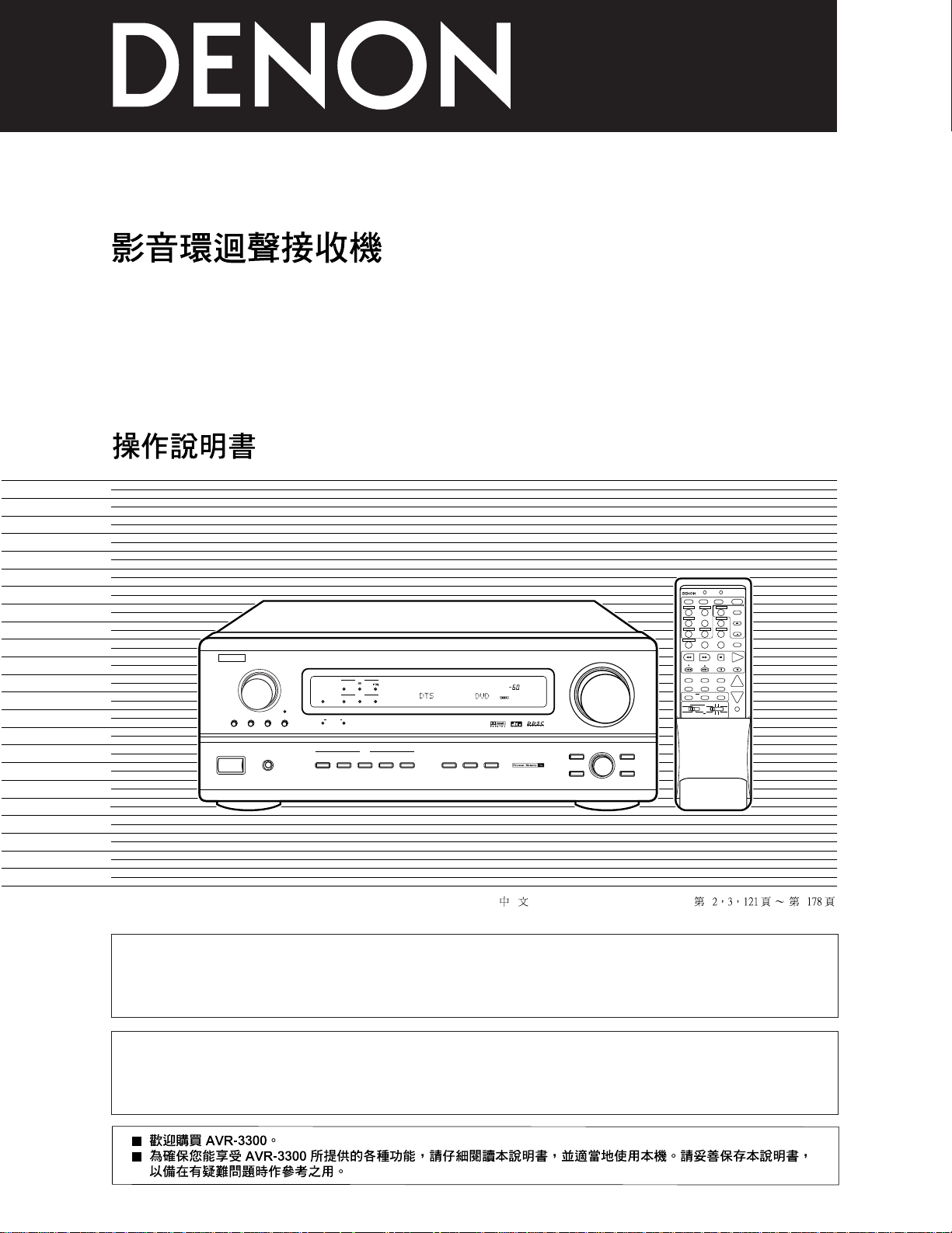
2 We greatly appreciate your purchase of the AVR-3300.
2 To be sure you take maximum advantage of all the features the AVR-3300 has to offer, read these instructions
carefully and use the set properly. Be sure to keep this manual for future reference should any questions or
problems arise.
2 Nous vous remercions de l’achat de l’AVR-3300.
2 Pour être sûr de profiter au maximum de toutes les caractéristiques qu’a à offrir l’AVR-3300, lire avec soin ces
instructions et bien utiliser l’appareil. Toujours conserver ce mode d’emploi pour s’y référer ultérieurement en
cas de question ou de problème.
FOR ENGLISH READERS PAGE 02 ~ PAGE 062
POUR LES LECTEURS FRANCAIS PAGE 2, 3, 63 ~ PAGE 120
2
2
SAFETY PRECAUTIONS
CAUTION:
TO REDUCE THE RISK OF ELECTRIC SHOCK, DO
NOT REMOVE COVER (OR BACK). NO USERSERVICEABLE PARTS INSIDE. REFER SERVICING
TO QUALIFIED SERVICE PERSONNEL.
The lightning flash with arrowhead symbol, within an
equilateral triangle, is intended to alert the user to the
presence of uninsulated “dangerous voltage” within
the product’s enclosure that may be of sufficient
magnitude to constitute a risk of electric shock to
persons.
The exclamation point within an equilateral triangle is
intended to alert the user to the presence of important
operating and maintenance (servicing) instructions in
the literature accompanying the appliance.
CAUTION
TO PREVENT ELECTRIC SHOCK DO NOT USE THIS (POLARIZED)
PLUG WITH AN EXTENSION CORD, RECEPTACLE OR OTHER
OUTLET UNLESS THE BLADES CAN BE FULLY INSERTED TO
PREVENT BLADE EXPOSURE.
ATTENTION
POUR PREVENIR LES CHOCS ELECTRIQUES NE PAS UTILISER
CETTE FICHE POLARISEE AVEC UN PROLONGATEUR UNE
PRISE DE COURANT OU UNE AUTRE SORTIE DE COURANT,
SAUF SI LES LAMES PEUVENT ETRE INSEREES A FOND SANS
EN LAISSER AUCUNE PARTIE A DECOUVERT.
This device complies with Part 15 of the FCC Rules. Operation is subject to
the following two conditions: (1) This device may not cause harmful
interference, and (2) this device must accept any interference received,
including interference that may cause undesired operation.
This Class B digital apparatus meets all requirements of the Canadian
Interference-Causing Equipment Regulations.
Cet appareil numérique de la classe B respecte toutes les exigences du
Règlement sur le matériel brouilleur du Canada.
“SERIAL NO.
PLEASE RECORD UNIT SERIAL NUMBER ATTACHED TO THE REAR OF THE
CABINET FOR FUTURE REFERENCE”
“NO. DE SERIE
PRIERE DE NOTER LE NUMERO DE SERIE DE L’APPAREIL INSCRIT A L’ARRIERE
DU COFFRET DE FAÇON A POUVOIR LE CONSULTER EN CAS DE PROBLEME.”
WARNING:
TO PREVENT FIRE OR SHOCK HAZARD, DO NOT EXPOSE
THIS APPLIANCE TO RAIN OR MOISTURE.
•
FOR U.S.A. & CANADA MODEL ONLY
•
POUR LES MODELE CANADIEN UNIQUEMENT
3
2
NOTE ON USE / OBSERVATIONS RELATIVES A L’UTILISATION
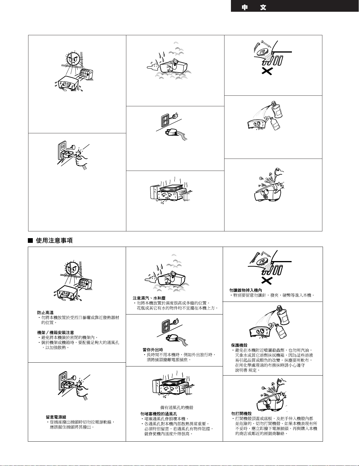
• Avoid high temperatures.
Allow for sufficient heat dispersion when
installed on a rack.
• Eviter des températures élevées
Tenir compte d’une dispersion de chaleur
suffisante lors de l’installation sur une étagère.
• Handle the power cord carefully.
Hold the plug when unplugging the cord.
• Manipuler le cordon d’alimentation avec
précaution.
Tenir la prise lors du débranchement du cordon.
• Keep the set free from moisture, water, and
dust.
• Protéger l’appareil contre l’humidité, l’eau et
lapoussière.
• Unplug the power cord when not using the set
for long periods of time.
• Débrancher le cordon d’alimentation lorsque
l’appareil n’est pas utilisé pendant de longues
périodes.
* (For sets with ventilation holes)
• Do not obstruct the ventilation holes.
• Ne pas obstruer les trous d’aération.
• Do not let foreign objects in the set.
• Ne pas laisser des objets étrangers dans
l’appareil.
• Do not let insecticides, benzene, and thinner
come in contact with the set.
• Ne pas mettre en contact des insecticides, du
benzène et un diluant avec l’appareil.
• Never disassemble or modify the set in any
way.
• Ne jamais démonter ou modifier l’appareil
d’une manière ou d’une autre.
ENGLISHFRANCAIS
4
SAFETY INSTRUCTIONS
1. Read Instructions – All the safety and operating instructions
should be read before the appliance is operated.
2. Retain Instructions – The safety and operating instructions
should be retained for future reference.
3. Heed Warnings – All warnings on the appliance and in the
operating instructions should be adhered to.
4. Follow Instructions – All operating and use instructions
should be followed.
5. Water and Moisture – The appliance should not be used
near water – for example, near a bathtub, washbowl,
kitchen sink, laundry tub, in a wet basement, or near a
swimming pool, and the like.
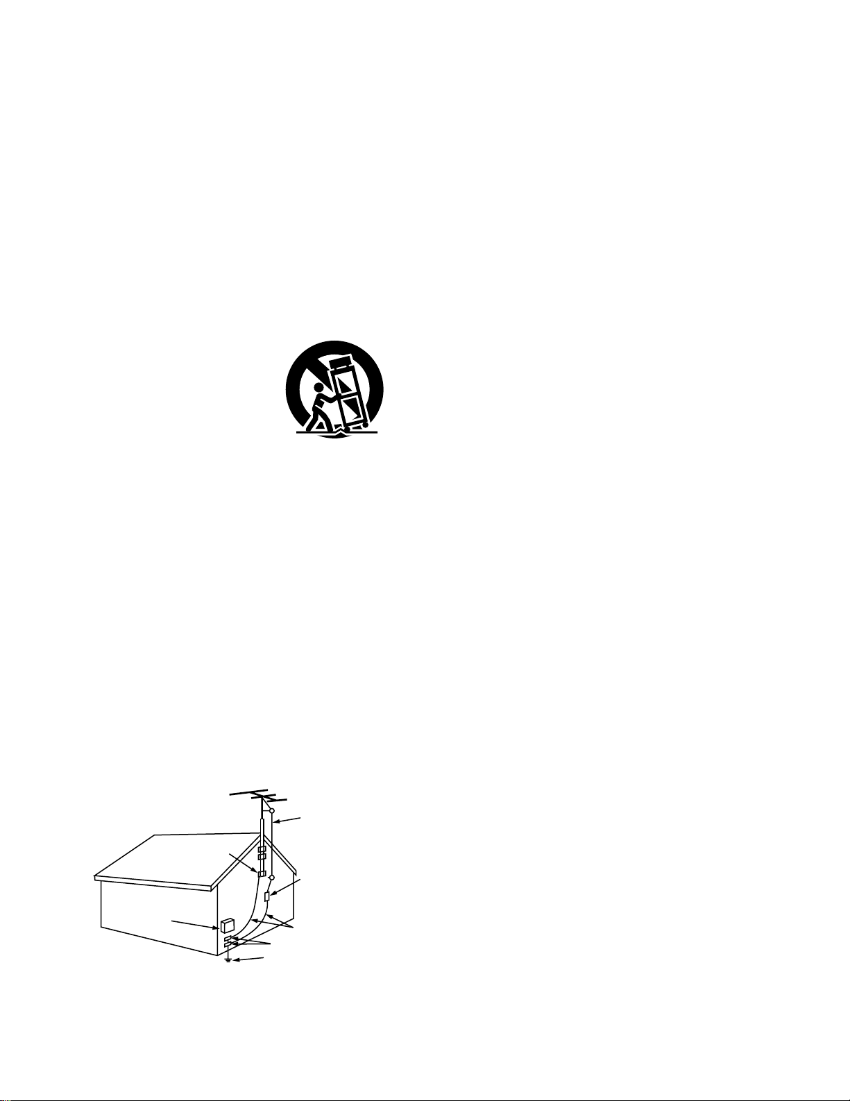
6. Carts and Stands – The appliance should be used only with
a cart or stand that is recommended by the manufacturer.
6A. An appliance and cart
combination should be
moved with care.
Quick stops, excessive
force, and uneven
surfaces may cause
the appliance and cart
combination to overturn.
7. Wall or Ceiling Mounting – The appliance should be
mounted to a wall or ceiling only as recommended by the
manufacturer.
8. Ventilation – The appliance should be situated so that its
location or position does not interfere with its proper
ventilation. For example, the appliance should not be
situated on a bed, sofa, rug, or similar surface that may
block the ventilation openings; or, placed in a built-in
installation, such as a bookcase or cabinet that may impede
the flow of air through the ventilation openings.
9. Heat – The appliance should be situated away from heat
sources such as radiators, heat registers, stoves, or other
appliances (including amplifiers) that produce heat.
10. Power Sources – The appliance should be connected to a
power supply only of the type described in the operating
instructions or as marked on the appliance.
11. Grounding or Polarization – Precautions should be taken so
that the grounding or polarization means of an appliance is
not defeated.
12. Power-Cord Protection – Power-supply cords should be
routed so that they are not likely to be walked on or pinched
by items placed upon or against them, paying particular
attention to cords at plugs, convenience receptacles, and
the point where they exit from the appliance.
14. Cleaning – The appliance should be cleaned only as
recommended by the manufacturer.
15. Power Lines – An outdoor antenna should be located away
from power lines.
16. Outdoor Antenna Grounding – If an outside antenna is
connected to the receiver, be sure the antenna system is
grounded so as to provide some protection against voltage
surges and built-up static charges. Article 810 of the
National Electrical Code, ANSI/NFPA 70, provides
information with regard to proper grounding of the mast and
supporting structure, grounding of the lead-in wire to an
antenna-discharge unit, size of grounding conductors,
location of antenna-discharge unit, connection to grounding
electrodes, and requirements for the grounding electrode.
See Figure A.
17. Nonuse Periods – The power cord of the appliance should
be unplugged from the outlet when left unused for a long
period of time.
18. Object and Liquid Entry – Care should be taken so that
objects do not fall and liquids are not spilled into the
enclosure through openings.
19. Damage Requiring Service – The appliance should be
serviced by qualified service personnel when:
A. The power-supply cord or the plug has been damaged; or
B. Objects have fallen, or liquid has been spilled into the
appliance; or
C. The appliance has been exposed to rain; or
D. The appliance does not appear to operate normally or
exhibits a marked change in performance; or
E. The appliance has been dropped, or the enclosure
damaged.
20. Servicing – The user should not attempt to service the
appliance beyond that described in the operating
instructions. All other servicing should be referred to
qualified service personnel.
FIGURE A
EXAMPLE OF ANTENNA GROUNDING
AS PER NATIONAL
ELECTRICAL CODE
ANTENNA
LEAD IN
WIRE
GROUND
CLAMP
ELECTRIC
SERVICE
EQUIPMENT
ANTENNA
DISCHARGE UNIT
(NEC SECTION 810-20)
GROUNDING CONDUCTORS
(NEC SECTION 810-21)
GROUND CLAMPS
POWER SERVICE GROUNDING
ELECTRODE SYSTEM
(NEC ART 250, PART H)
NEC — NATIONAL ELECTRICAL CODE
5
ENGLISH
2
INTRODUCTION
2
ACCESSORIES
Thank you for choosing the DENON AVR-3300 Digital Surround A / V receiver. This remarkable component has been engineered to provide superb
surround sound listening with AV theater sources such as DVD, as well as providing outstanding high fidelity reproduction of your favorite music
sources.
As this product is provided with an immense array of features, we recommend that before you begin hookup and operation that you review the
contents of this manual before proceeding.
TABLE OF CONTENTS
z Before Using ……………………………………………………………………5
x Cautions on Installation ………………………………………………………5
c Cautions on Handling …………………………………………………………6
v Features …………………………………………………………………………6
b Connections …………………………………………………………………7~14
n Part Names and Functions ………………………………………………15, 16
m Setting up the system ……………………………………………………17~28
, Remote Control Unit………………………………………………………29~37
. Operation …………………………………………………………………37~43
⁄0 Surround ……………………………………………………………………44~47
⁄1 DSP Surround Simulation…………………………………………………48~52
⁄2 Listening to the Radio ……………………………………………………52~55
⁄3 Last Function Memory ………………………………………………………55
⁄4 Initialization of the Microprocessor …………………………………………55
⁄5 Troubleshooting…………………………………………………………………56
⁄6 Additional Information ……………………………………………………57~61
⁄7 Specifications …………………………………………………………………62
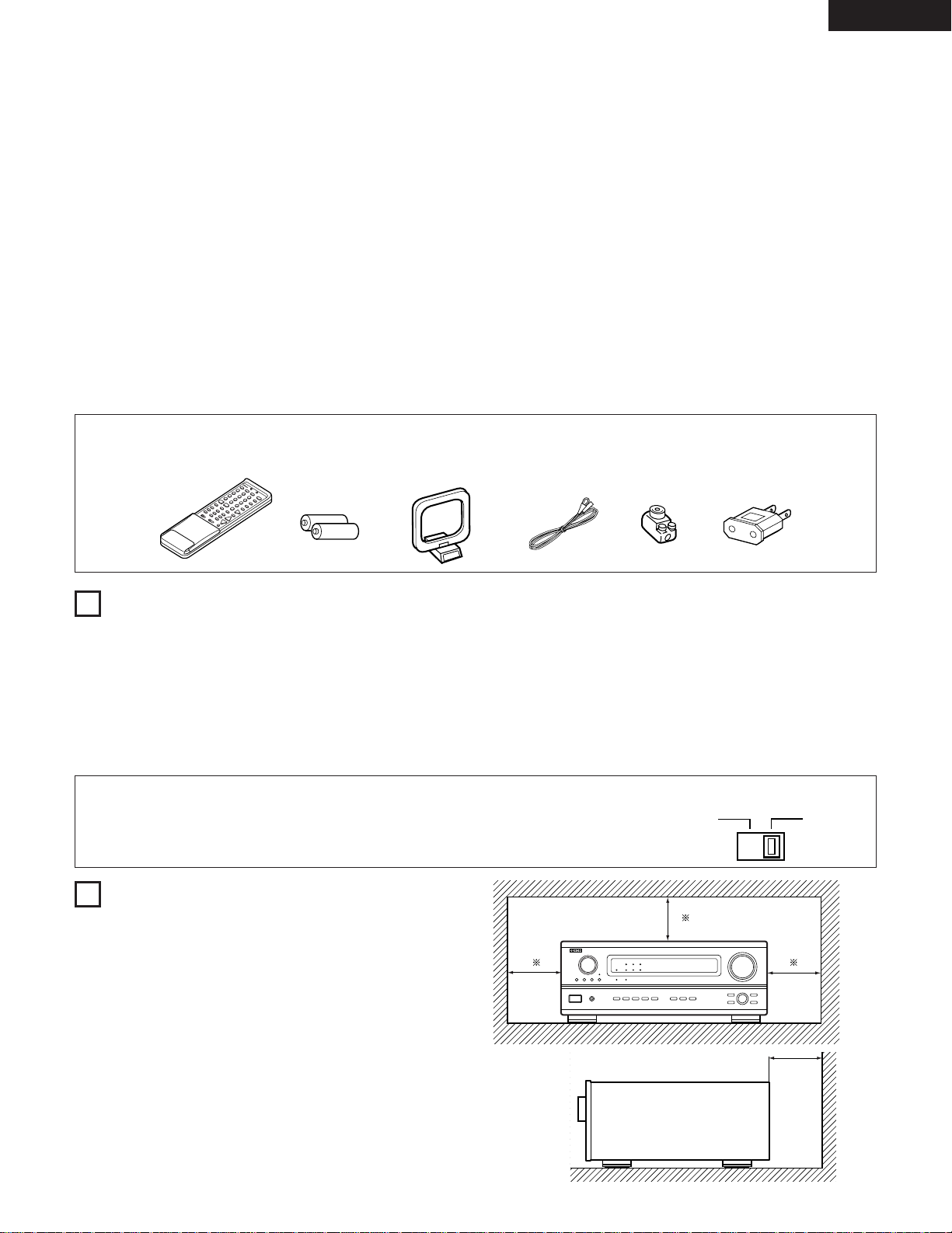
Check that the following parts are included in addition to the main unit:
① Operating instructions…..1 ② Warranty ( for North America model only )………………..1 ➂ Service station list………..1 ➃ Remote control unit
➄ R6P/AA batteries……..….2 ➅AM loop antenna………………1 ➆ FM indoor antenna…1 ⑧ FM antenna adaptor……..1 (RC-860)…………………1
⑨ AC plug adapter (for Multiple voltage model only)………………1
1
2
BEFORE USING
CAUTIONS ON INSTALLATION
Pay attention to the following before using this unit:
• Moving the set
To prevent short circuits or damaged wires in the connection cords, always
unplug the power cord and disconnect the connection cords between all
other audio components when moving the set.
• Before turning the power switch on
Check once again that all connections are proper and that there are not
problems with the connection cords. Always set the power switch to the
standby position before connecting and disconnecting connection cords.
Noise or disturbance of the picture may be generated if this unit or any other
electronic equipment using microprocessors is used near a tuner or TV.
If this happens, take the following steps:
• Install this unit as far as possible from the tuner or TV.
• Set the antenna wires from the tuner or TV away from this unit’s power cord
and input/output connection cords.
• Noise or disturbance tends to occur particularly when using indoor antennas
or 300 Ω/ohms feeder wires. We recommend using outdoor antennas and
75 Ω/ohms coaxial cables.
For heat dispersal, leave at least 10 cm/4 inch of space between the top,
back and sides of this unit and the wall or other components.
• Store this instructions in a safe place.
After reading, store this instructions along with the warranty in a safe place.
• Note that the illustrations in this instructions may differ from the actual
set for explanation purposes.
10 cm/4 inch or more
10 cm/4 inch or more
Wall
• Line Voltage Selection (for multiple voltage model only)
*
The desired voltage may be set with the VOLTAGE SELECTOR knob on the rear panel, using a screwdriver.
*
If the VOLTAGE SELECTOR knob does not move smoothly, please contact a qualified serviceman.
VOLTAGE SELECTOR
115V 230V

6
ENGLISH
3
CAUTIONS ON HANDLING
4
FEATURES
• Switching the input function when input jacks are not
connected
A clicking noise may be produced if the input function is switched
when nothing is connected to the input jacks. If this happens, either
turn down the MASTER VOLUME control or connect components
to the input jacks.
• Muting of PRE OUT jacks, HEADPHONE jack and SPEAKER
terminals
The PRE OUT jacks, HEADPHONE jacks and SPEAKER terminals
include a muting circuit. Because of this, the output signals are
greatly reduced for several seconds after the power switch is
turned on or input function, surround mode or any other-set-up is
changed. If the volume is turned up during this time, the output will
be very high after the muting circuit stops functioning. Always wait
until the muting circuit turns off before adjusting the volume.
• Whenever the power switch is in the £ OFF or STANDBY
state, the apparatus is still connected on AC line voltage.
Please be sure to unplug the cord when you leave home for,
say, a vacation.
1. Digital Surround Sound Decoding
Featuring 32 bit high speed DSP, operating entirely in digital
domain, surround sound from digital sources such as DVD, LD,
DTV and satellite are faithfully re-created.
2. Dolby Digital
Using advanced digital processing algorithms, Dolby Digital
provides up to 5.1 channels of wide-range, high fidelity surround
sound. Dolby Digital is the default digital audio delivery system for
North American DVD and DTV.
3. DTS (Digital Theater Systems)
DTS provides up to 5.1 channels of wide-range, high fidelity
surround sound, from sources such as laser disc, DVD and
specially-encoded music discs.
4. 24 bit D/A Conversion
All six channels, including the five main channels and the low
frequency effects (LFE) channel benefit from reference, for
optimum high fidelity reproduction of music and movie
soundtracks.
5. Dual Surround Speaker Mode
Provides for the first time the ability to optimize surround sound
reproduction using two different types of surround sound speakers
as well as two different surround speaker positions:
(1) Movie Surround
Motion picture soundtracks use the surround channel(s) to
provide the ambient elements of the acoustic environment they
want the audience to realize. This is best accomplished by the
use of specially-designed surround speakers that offer a wide
diffusion pattern (bipolar dispersion) or by using surround
speakers that provide broad dispersion with a minimum of onaxis localization (dipolar dispersion). Side wall mounting (closer
to the ceiling) of the surround speakers provides the greatest
envelopment, minimizing localization of direct sound from the
speakers.
(2) Music Surround
With full range discrete surround channels, as well as three
discrete full range front channels, digital formats such as Dolby
and DTS offer thrilling surround sound music listening.
Producers of multi-channel discrete digital music recordings
almost always favor the use of direct radiating (monopolar)
surround speakers, placed in the rear corners of the room,
since that is how they configure their studios during the
mixing/creation process.
The DENON AVR-3300 provides the ability to connect two
different sets of surround speakers, and place them in the
appropriate locations in your AV theater room, so that you can
enjoy both movie soundtracks and music listening, with
optimum results and no compromise.
6. Component Video Switching
In addition to composite video and “S” video switching, the AVR3300 provides 2 sets of component video (Y, R-Y, B-Y) inputs for
the DVD and TV/DBS inputs, and one set of component video
outputs to the television, for superior picture quality.
7. Video Select Function
Allow you to watch one source (visual) while listening to another
source (audio).
8. Future Sound Format Upgrade Capability via Eight Channel
Inputs & Outputs
For future multi-channel audio format(s), the AVR-3300 is provided
with 7.1 channel (seven main channels, plus one low frequency
effects channel) inputs, along with a full set of 7.1 channel pre-amp
outputs, controlled by the 8 channel master volume control. This
assures future upgrade possibilities for any future multi-channel
sound format.
RLR
L
R
INPUT OUTPUT
LRL
R
OUTPUT
L
R
L
SWITCHED
TOTAL 120W(1A.)MAX.
AC 120V 60HZ
AC OUTLETS
SAME AS LINE-VOLTAGE
SWITCHED 100W MAX.
AC OUTLET
OUTPUT
OPTICAL COAXIAL
OUTPUT
OPTICAL
IN
IN
OUT
IN IN OUT
SIGNAL
GND
DVD
EXT. INFREQ. STEP
VDP
TV
/
DBS
VCR-2/
V.AUX
COAXIAL
VCR-2/
V.AUX
MD/
TAPE
MD/
TAPE
VCR-1
VCR-1OPT.-1
OPT.-2
OPT.-3
FR
LOOP
ANT.
AM
SW
SR
ER
CD
PHONO
FL
C
SL
EL
DVD TV/DBS MONITOR
YYC
BCB CRCRYCB CR
COMPONENT VIDEO
SPEAKER SYSTEMS
AUDIO
DIGITAL
C-VIDEO
MONITOR
S-VIDEO
PRE OUT
L L
R
R L
R L
R L
R L
R L
R
FM
COAX.
75
B
R L
A
FRONT
FRONT CENTER SURROUND SURROUND
SUB
WOOFER
CENTER
SURROUNDEFFECT
MULTI/
ANTENNA
9kHz
10kHz
VOLTAGE SELECTOR
115V 230V
AC OUTLET
SAME AS LINE-VOLTAGE
SWITCHED 100W MAX.
L
R
L
R
L
R
L
R
DIGITAL AUDIODIGITAL AUDIO
DIGITAL AUDIODIGITAL AUDIO
7
ENGLISH
5
CONNECTIONS
• Do not plug in the AC cord until all connections have been completed.
• Be sure to connect the left and right channels properly (left with left, right
with right).
• Insert the plugs securely. Incomplete connections will result in the
generation of noise.
• Use the AC OUTLETS for audio equipment only. Do not use them for
hair driers, etc.
• Note that binding pin plug cords together with AC cords or placing them
near a power transformer will result in generating hum or other noise.
• Noise or humming may be generated if a connected audio equipment is
used independently without turning the power of this unit on. If this
happens, turn on the power of the this unit.
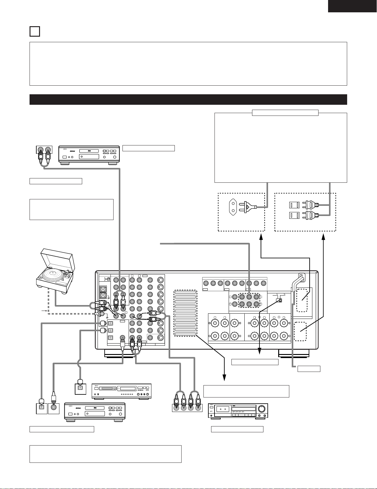
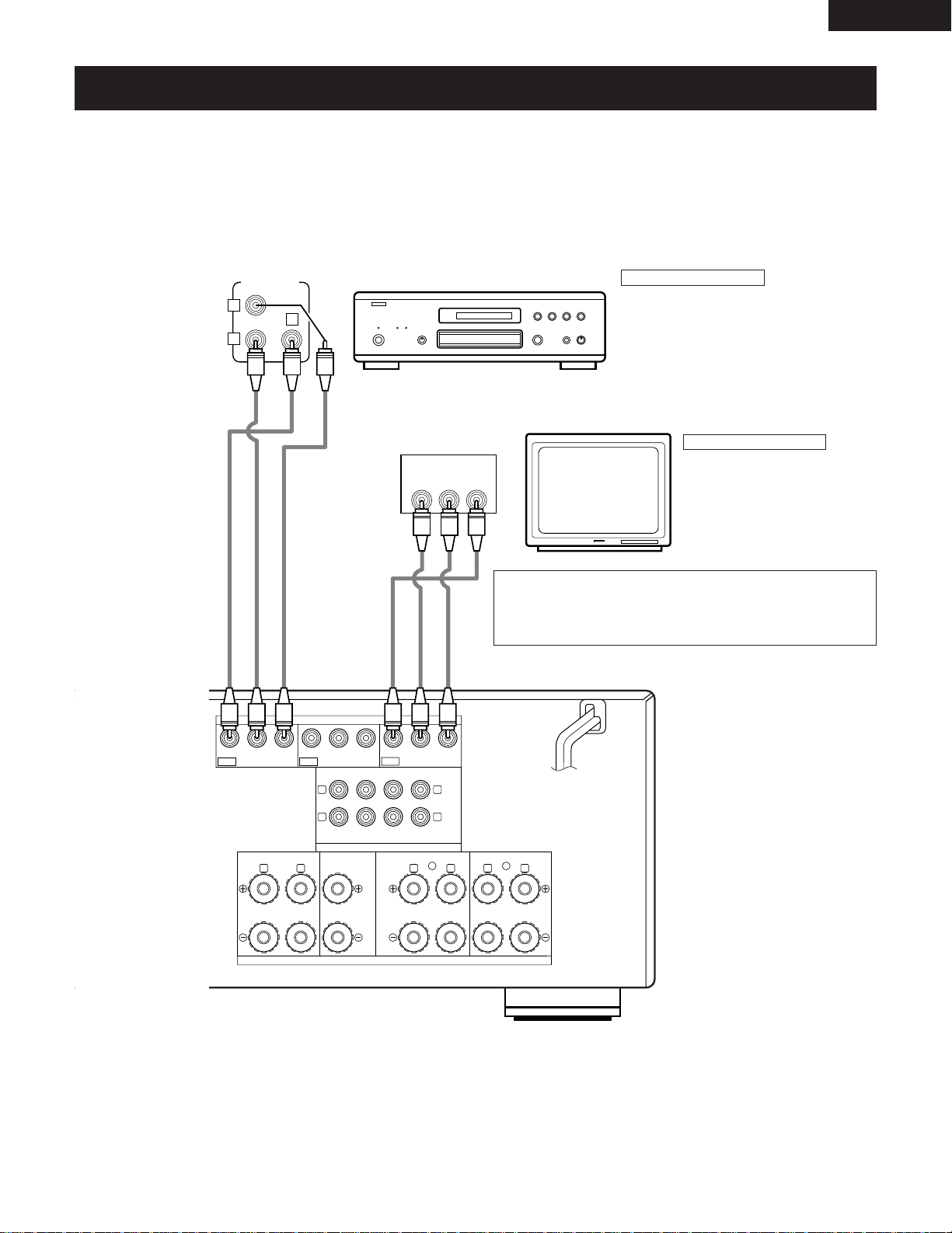
Connecting the audio components
• When making connections, also refer to the operating instructions of the other
components.
The power to these outlets is turned on and off when the power is switched between on
and standby from the remote control unit or power switch.
CD player
Connecting a CD player
Connect the CD player’s analog output
jacks (ANALOG OUTPUT) to this unit’s CD
jacks using pin plug cords.
Connecting a turntable
Connect the turntable’s output cord to the AVR3300’s PHONO jacks, the L (left) plug to the L jack,
the R (right) plug to the right jack.
NOTE:
This unit cannot be used with MC cartridges
directly. Use a separate head amplifier or step-up
transformer.
If humming or other noise is generated
when the ground wire is connected,
disconnect the ground wire.
Turntable
(MM cartridge)
Ground
wire
Connecting the pre-out jacks
Use these jacks if you wish to connect external power amplifier(s) to
increase the power of the front, center and surround sound channels, or for
connection to powered loudspeakers.
AC OUTLETS
• SWITCHED
(total capacity – 120 W (1 A.) – for North America model)
(total capacity – 100 W – for multiple voltage model)
The power to these outlets is turned on and off in conjunction with the
POWER operation switch on the main unit, and when the power is switched
between on and standby from the remote control unit. (Multiple voltage
model only)
No power is supplied from these outlets when this unit’s power is at standby.
Never connect equipment whose total capacity is above 120 W (1 A.) for
North America model (100 W for multiple voltage model).
NOTE:
Only use the AC OUTLETS for audio equipment. Never use them for hair
driers, TVs or other electrical appliances.
Connecting the AC OUTLTETS
VOLTAGE SELECTOR
For multiple voltage
model only
(Refer to page 5.)
AC CORD
AC 120 V, 60 Hz
(North America model)
AC 115/230 V, 50/60 Hz
(Multiple voltage model)
Connecting a tape deck
Connections for recording:
Connect the tape deck’s recording input jacks (LINE IN or REC) to this unit’s tape
recording (MD/TAPE OUT) jacks using pin plug cords.
Connections for playback:
Connect the tape deck’s playback output jacks (LINE OUT or PB) to this unit’s tape
playback (MD/TAPE IN) jacks using pin plug cords.
Tape deck or MD recorder
Route the connection cords, etc., in such a way
that they do not obstruct the ventilation holes.
MD recorder, DAT deck or other component
equipped with digital output jacks
CD player or other
component equipped
with digital output jacks
Connecting the DIGITAL jacks
Use these for connections to audio equipment with digital output. Refer to page 25 for
instructions on setting this terminal.
NOTES:
• Use 75 Ω/ohms cable pin cords for coaxial connections.
• Use optical cables for optical connections, removing the cap before connecting.
for Multiple voltage model for North America model
IN
IN
OUT
IN IN OUT
SIGNAL
GND
DVD
EXT. INFREQ. STEP
VDP
TV
/
DBS
VCR-2/
V.AUX
COAXIAL
VCR-2/
V.AUX
MD/
TAPE
MD/
TAPE
VCR-1
VCR-1OPT.-1
OPT.-2
OPT.-3
FR
LOOP
ANT.
AM
SW
SR
ER
CD
PHONO
FL
C
SL
EL
DVD TV/DBS MONITOR
YYC
BCB CRCRYCB CR
COMPONENT VIDEO
SPEAKER SYSTEMS
AUDIO
DIGITAL
C-VIDEO
MONITOR
S-VIDEO
PRE OUT
L L
R
R L
R L
R L
R L
R L
R
FM
COAX.
75
B
R L
A
FRONT
FRONT CENTER SURROUND SURROUND
SUB
WOOFER
CENTER
SURROUNDEFFECT
MULTI/
ANTENNA
9kHz
10kHz
IN
VIDEO
R
L
R OUT IN
AUDIO
VIDEO
OUT IN
LRL
RLR
L
R OUT IN
AUDIO
VIDEO
OUT IN
LRL
R
L
R
L
R OUT
VIDEO
OUT
L
AUDIO
L
R
R OUT
VIDEO
OUT
L
AUDIO
L
R
R
L
R
L
R
L
R
L
R
L
8
ENGLISH
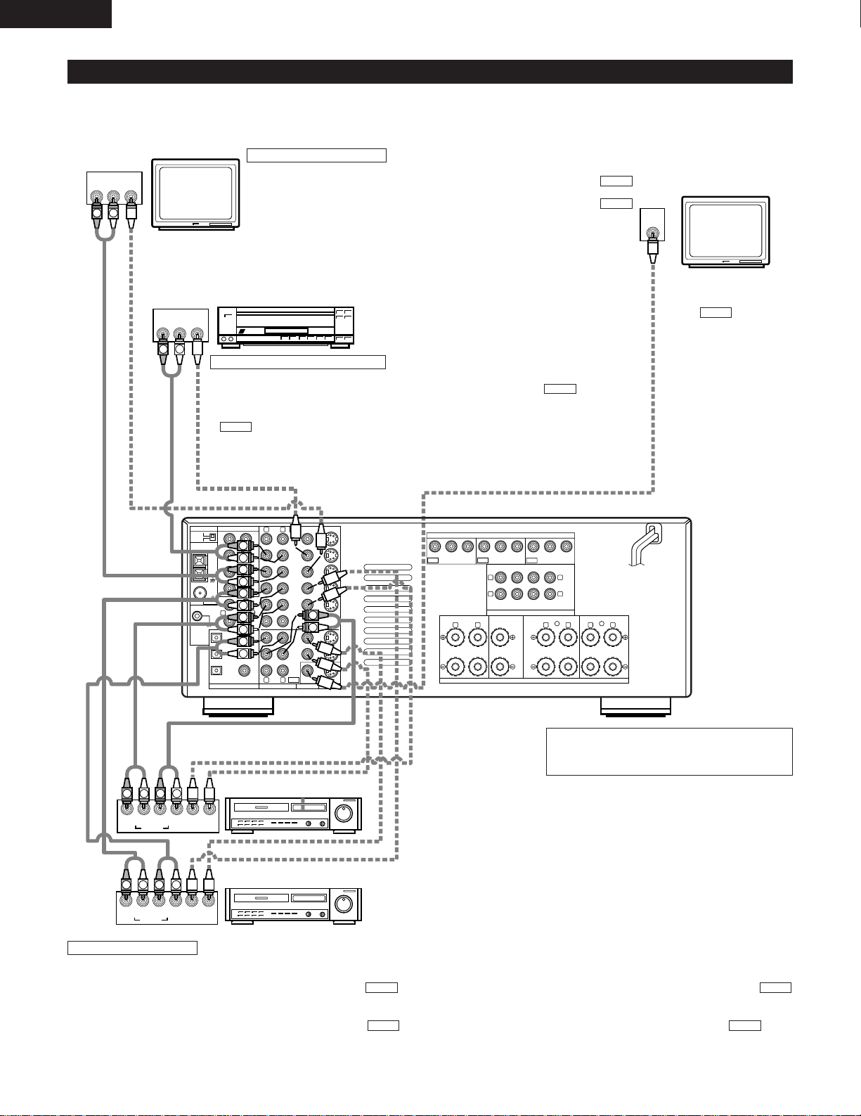
Connecting video components
• To connect the video signal, connect using a 75 Ω/ohms video signal cable cord. Using an improper cable can result in a drop in video quality.
• When making connections, also refer to the operating instructions of the other components.
TV or DBS tuner
Connecting a TV/DBS tuner
TV/DBS
• Connect the TV’s or DBS tuner’s video output jack (VIDEO OUTPUT) to the
(yellow) TV/DBS IN jack using a 75 Ω/ohms video coaxial pin plug cord.
• Connect the TV’s or DBS tuner’s audio output jacks (AUDIO OUTPUT) to the
TV/DBS IN jacks using pin plug cords.
AUDIO
VIDEO
LD player, CDV player, etc.
Connecting a video disc player VDP
VDP
• Connect the video disc player’s video output jack (VIDEO OUTPUT) to the (yellow) VDP IN
jack using a 75 Ω/ohms video coaxial pin plug cord.
• Connect the video disc player’s analog audio output jacks (ANALOG AUDIO OUTPUT) to the
VDP IN jacks using pin plug cords.
• A DVD player can be connected to the DVD jacks in the same way.
• It is also possible to connect a video disc player, DVD player, video camcorder, game machine, etc.,
to the VCR-2/V.AUX jacks.
AUDIO
VIDEO
Monitor TV
MONITOR OUT
• Connect the TV’s video
input jack (VIDEO INPUT) to
the MONITOR
OUT jack using a 75
Ω/ohms video coaxial pin
plug cord.
VIDEO
Note on connecting the digital input jacks
• Only audio signals are input to the digital input jacks.
For details, see page 7.
Video deck 2
Video deck 1
Connecting a video decks
• There are two sets of video deck (VCR) jacks, so two video decks can be connected for simultaneous recording or video copying.
Video input/output connections:
• Connect the video deck’s video output jack (VIDEO OUT) to the (yellow) VCR-1 IN jack, and the video deck’s video input jack (VIDEO IN) to the
(yellow) VCR-1 OUT jack using 75 Ω/ohms video coaxial pin plug cords.
Connecting the audio output jacks
• Connect the video deck’s audio output jacks (AUDIO OUT) to the VCR-1 IN jacks, and the video deck’s audio input jacks (AUDIO IN) to the VCR-1
OUT jacks using pin plug cords.
*
Connect the second video deck to the VCR-2/V.AUX jacks in the same way.
AUDIOAUDIO
VIDEOVIDEO
IN
IN
OUT
IN IN OUT
SIGNAL
GND
DVD
EXT. INFREQ. STEP
VDP
TV
/
DBS
VCR-2/
V.AUX
COAXIAL
VCR-2/
V.AUX
MD/
TAPE
MD/
TAPE
VCR-1
VCR-1OPT.-1
OPT.-2
OPT.-3
FR
LOOP
ANT.
AM
SW
SR
ER
CD
PHONO
FL
C
SL
EL
DVD TV/DBS MONITOR
YYC
BCB CRCRYCB CR
COMPONENT VIDEO
SPEAKER SYSTEMS
AUDIO
DIGITAL
C-VIDEO
MONITOR
S-VIDEO
PRE OUT
L L
R
R L
R L
R L
R L
R L
R
FM
COAX.
75
B
R L
A
FRONT
FRONT CENTER SURROUND SURROUND
SUB
WOOFER
CENTER
SURROUNDEFFECT
MULTI/
ANTENNA
9kHz
10kHz
VOLTAGE SELECTOR
115V 230V
AC OUTLET
SAME AS LINE-VOLTAGE
SWITCHED 100W MAX.
IN
S-VIDEO
OUT
S-VIDEO
OUT
S-VIDEO
OUT IN
S-VIDEO
OUT IN
S-VIDEO
9
ENGLISH
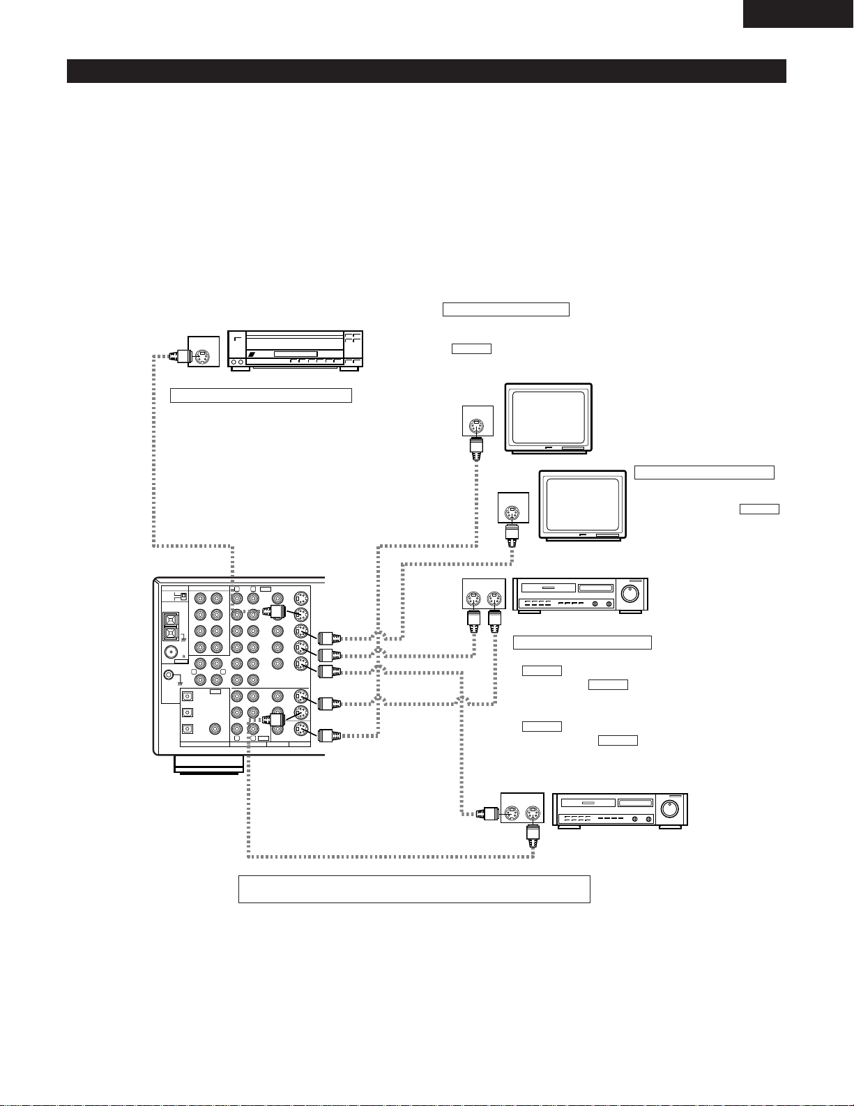
Connecting a video component equipped with S-Video jacks
• When making connections, also refer to the operating instructions of the other components.
• A note on the S input jacks
The input selectors for the S inputs and pin jack inputs work in conjunction with each other.
• Precaution when using S-jacks
This unit’s S-jacks (input and output) and video pin jacks (input and output) have independent circuit structures, so that video signals input from
the S-jacks are only output from the S-jack outputs and video signals input from the pin jacks are only output from the pin jack outputs.
When connecting this unit with equipment that is equipped with S-jacks, keep the above point in mind and make connections according to the
equipment’s instruction manuals.
LD player, CDV player, etc.
Connecting a video disc player (VDP)
VDP
• Connect the video disc player’s S-Video output jack to the SVIDEO VDP IN jack using an S-Video connection cord.
• A DVD player can be connected to the DVD jacks in the same
way.
• It is also possible to connect a video disc player, DVD player,
video camcorder, game machine, etc., to the VCR-2/V.AUX
jacks.
Connecting a monitor TV
MONITOR OUT
• Connect the TV’s or DBS tuner’s S video input (S-VIDEO INPUT) to the
MONITOR OUT jack using a S jack connection cord.
S-VIDEO
Monitor TV
Connecting a TV/DBS tuner
• Connect the TV’s or DBS tuner’s
S video output jack (S-VIDEO
OUTPUT) to the
TV/DBS IN jack using an S jack
connection cord.
S-VIDEO
TV or satellite broadcast tuner
Video deck 1
Connecting the video decks
• Connect the video deck’s S output jack (S-OUT) to the
VCR-1 IN jack and the video deck’s S input jack
(S-IN) to the VCR-1 OUT jack using S jack
connection cords.
• Connect the video deck’s S output jack (S-OUT) to the
VCR-2/V.AUX IN jack and the video deck’s S input
jack (S-IN) to the VCR-2/V.AUX OUT jack using S
jack connection cords.
S-VIDEO
S-VIDEO
S-VIDEO
S-VIDEO
Video deck 2
Connect the components’ audio inputs and outputs as described on page 7.
IN
IN
OUT
IN IN OUT
SIGNAL
GND
DVD
EXT. INFREQ. STEP
VDP
TV
/
DBS
VCR-2/
V.AUX
COAXIAL
VCR-2/
V.AUX
MD/
TAPE
MD/
TAPE
VCR-1
VCR-1OPT.-1
OPT.-2
OPT.-3
FR
LOOP
ANT.
AM
SW
SR
ER
CD
PHONO
FL
C
SL
EL
DVD TV/DBS
YY C
B CRYCB CR
COMPONENT VIDEO
SPEAKER S
AUDIO
DIGITAL
C-VIDEO
MONITOR
S-VIDEO
PRE OU
L
R
R L
R L
R L
R L
FM
COAX.
75
FRONT CENTER
SU
WOO
CENT
SURROUNDEFFECT
MULTI/
ANTENNA
9kHz
10kHz
10
ENGLISH
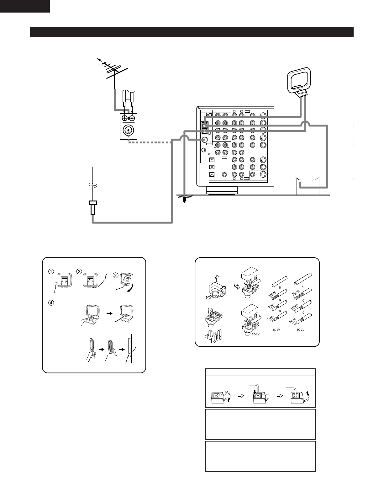
Connecting the antenna terminals
DIRECTION OF
BROADCASTING
STATION
75 Ω/ohms
COAXIAL
CABLE
FM ANTENNA
300 Ω/ohms
FEEDER
CABLE
FM INDOOR
ANTENNA
(An Accessory)
300 Ω/ohms
AM LOOP
ANTENNA
(An Accessory)
AM OUTDOOR
ANTENNA
GROUND
AM loop antenna assembly FM antenna adopter assembly
Connect to the AM
antenna terminals.
Remove the vinyl tie
and take out the
connection line.
Bend in the reverse
direction.
a. With the antenna
on top any stable
surface.
b. With the antenna
attached to a wall.
Mount
Installation hole
Mount on wall, etc.
75 Ω/ohms COAXIAL CABLE
Open the cover
ANTENNA ADAPTER
REMOVE
CLAMP
CLAMP
CLAMP
CLAMP
PULL
PULL
SHUT
SHUT
Connection of AM antennas
1. Push the lever. 2. Insert the conductor. 3. Return the lever.
Note to CATV system installer:
This reminder is provided to call the CATV system installer’s
attention to Article 820-40 of the NEC which provides guidelines
for proper grounding and, in particular, specifies that the cable
ground shall be connected to the grounding system of the
building, as close to the point of cable entry as practical.
Notes:
• Do not connect two FM antennas simultaneously.
• Even if an external AM antenna is used, do not disconnect the
AM loop antenna.
• Make sure AM loop antenna lead terminals do not touch metal
parts of the panel.
FM ANTENNA
ADAPTER
(An Accessory)
IN IN OUT
DVD TV/DBS MONITOR
YYC
BCB CRCRYCB CR
COMPONENT VIDEO
SPEAKER SYSTEMS
PRE OUT
L L
R
R L R L
R
B
R L
A
FRONT
FRONT CENTER SURROUND SURROUND
SUB
WOOFER
CENTER
SURROUNDEFFECT
MULTI/
YPrPb
B
B
VIDEO OUT
Pr
Y
Pb
COMPONENT
VIDEO IN
COMPONENT
11
ENGLISH
Connecting a Video Component Equipped with Color Difference (Component — Y, R-Y, B-Y) Video
Jacks (DVD Player)
• When making connections, also refer to the operating instructions of the other components.
• The signals input to the color difference (component) video jacks are not output from the VIDEO output jack (yellow) or the S-Video output jack.
In addition, the video signals input to the VIDEO input (yellow) and S-Video input jacks are not output to the color difference (component) video
jacks.
• The AVR-3300’s on-screen display signals are not output from the color difference (component) video output jacks (MONITOR OUT).
• Some video sources with component video outputs are labeled Y, Pb, Pr, or Y, Cb, Cr, or Y, R-Y, B-Y. These terms all refer to component video
color difference output.
DVD player
Connecting a DVD player
DVD IN jacks
• Connect the DVD player’s color difference
(component) video output jacks (COMPONENT
VIDEO OUTPUT) to the COMPONENT DVD IN jack
using 75 Ω/ohms coaxial video pin-plug cords.
• In the same way, another video source with
component video outputs such as a DTV/DBS
tuner, etc., can be connected to the TV/DBS color
difference (component) video jacks.
Monitor TV
Connecting a monitor TV
MONITOR OUT jack
• Connect the TV’s color difference
(component) video input jacks
(COMPONENT VIDEO INPUT) to the
COMPONENT MONITOR OUT jack
using 75 Ω/ohms coaxial video pinplug cords.
• The color difference input jacks may be indicated differently on
some TVs, monitors or video components (“Pr, Pb and Y”, “R-Y,
B-Y and Y”, “Cr, Cb and Y”, etc.). For details, carefully read the
operating instructions included with the TV or other component.
12
ENGLISH
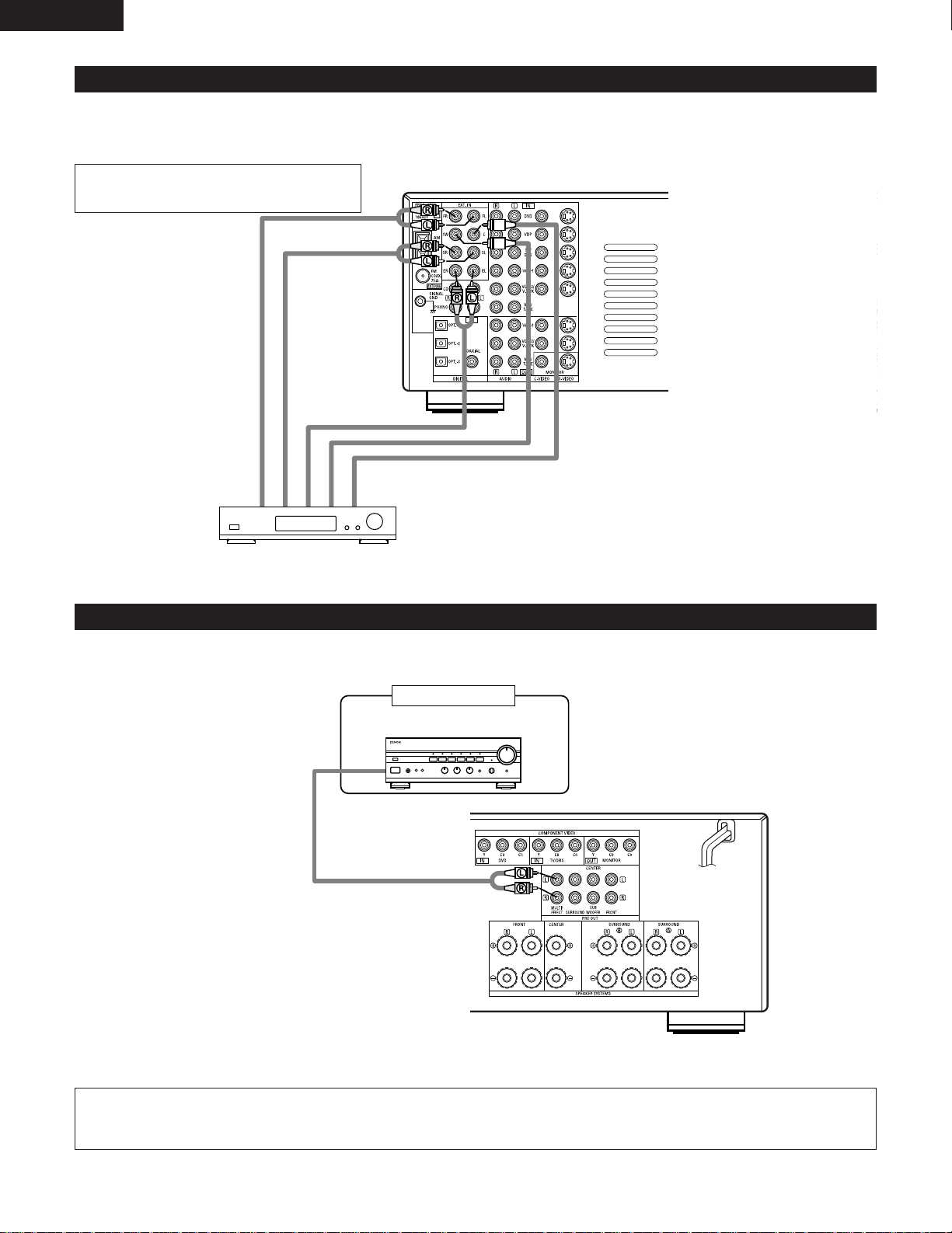
Connecting the external input (EXT. IN) jacks
• These input jacks are for inputting multi-channel audio signals in high definition MUSE 3-1 format, multi-channel audio signals from an MPEG
multi-channel decoder, or future multi-channel sound format, etc.
• When making connections, also refer to the operating instructions of the other components.
When connecting a high definition (MUSE 3-1 format)
component, use a separately sold mono/stereo cable if
the surround channel output is monaural.
Decoder with 8- or 6-channel
analog output
Front
Surround
Effect, etc.
Subwoofer
Center
*
For instructions on playback using the external input (EXT. IN) jacks, see page 43.
Connecting the MULTI SOURCE jacks
• If another pre-main (integrated) amplifier is connected, the multi-source jacks can be used to play a different program source in another room
at the same time. (See page 41.)
Another room
Integrated pre-main amplifier
*
For instructions on operations using the MULTI SOURCE jacks, see page 41 or page 43.
NOTE: EFFECT CH and MULTI cannot be used at the same time.
When making the setting, refer to “EXT. IN & MULTI” on page 26.
13
ENGLISH
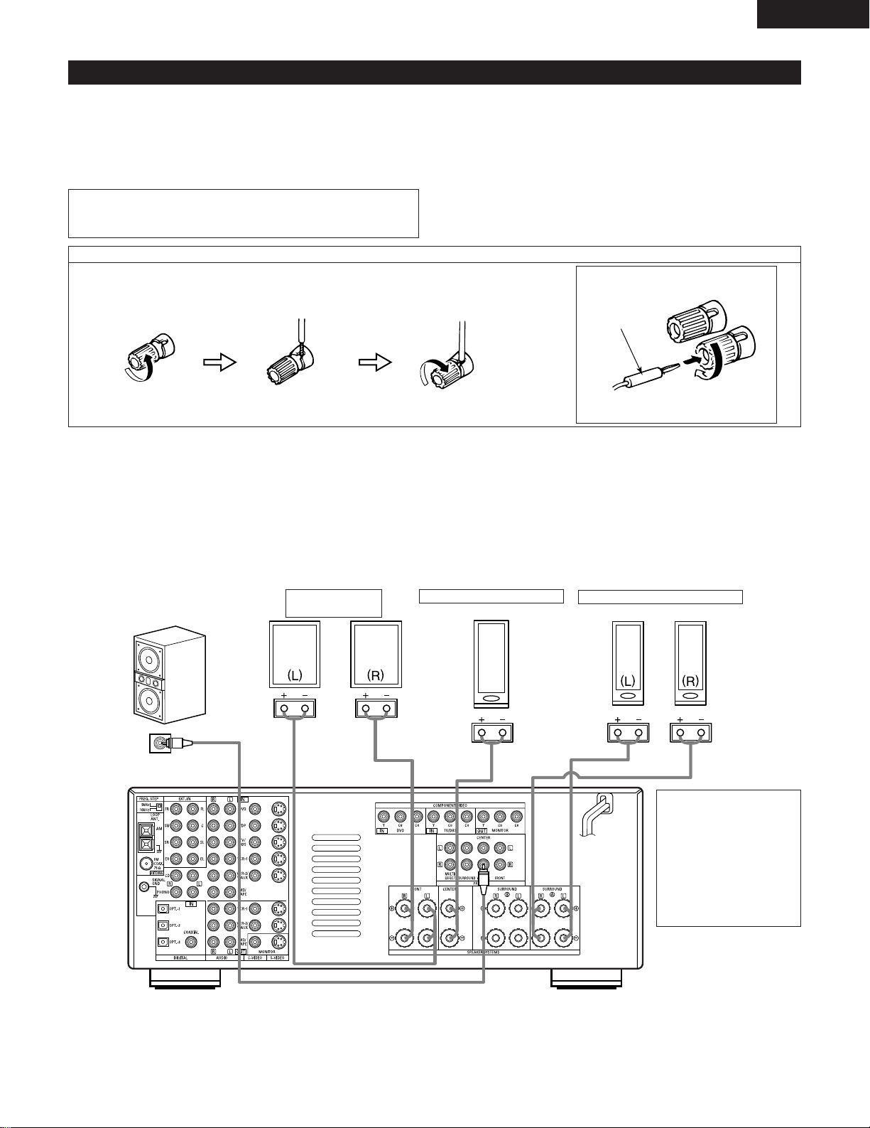
Speaker system connections
• Connect the speaker terminals with the speakers making sure that like
polarities are matched (≈ with ≈ , √ with √ ). Mismatching of polarities will
result in weak central sound, unclear orientation of the various instruments,
and the sense of direction of the stereo being impaired.
• When making connections, take care that none of the individual conductors
of the speaker cord come in contact with adjacent terminals, with other
speaker cord conductors, or with the rear panel.
NOTE:
NEVER touch the speaker terminals when the power is on.
Doing so could result in electric shocks.
Speaker Impedance
• Speakers with an impedance of from 6 to 16 Ω/ohms can be connected for
use as front and center speakers.
• Speakers with an impedance of 6 to 16 Ω/ohms can be connected for use as
surround speakers.
• Be careful when using two pairs of surround speakers (A + B) at the same
time, since use of speakers with an impedance of less than 8 Ω/ohms will
lead to damage.
• The protector circuit may be activated if the set is played for long periods of
time at high volumes when speakers with an impedance lower than the
specified impedance are connected.
Connection the speaker terminals
1. Loosen by turning
counterclockwise
2. Insert the cord. 3. Tighten by turning
clockwise.
Connecting banana plugs
(North America model only)
banana plug
Turn clockwise to tighten, then insert the
banana plug.
Connections
• When making connections, also refer to the operating instructions of the other components.
Connection jack for
subwoofer with built-in
amplifier (super woofer),
etc.
FRONT SPEAKER
SYSTEMS
CENTER SPEAKER SYSTEM
SURROUND SPEAKER SYSTEMS
• Precautions when
connecting speakers
If a speaker is placed near a
TV or video monitor, the
colors on the screen may
be disturbed by the
speaker’s magnetism. If
this should happen, move
the speaker away to a
position where it does not
have this effect.

14
ENGLISH
• This unit is equipped with a high-speed protection circuit. The purpose of this circuit is to protect the speakers under
circumstances such as when the output of the power amplifier is inadvertently short-circuited and a large current flows, when
the temperature surrounding the unit becomes unusually high, or when the unit is used at high output over a long period
which results in an extreme temperature rise.
When the protection circuit is activated, the speaker output is cut off and the power supply indicator LED flashes. Should
this occur, please follow these steps: be sure to switch off the power of this unit, check whether there are any faults with
the wiring of the speaker cables or input cables, and wait for the unit to cool down if it is very hot. Improve the ventilation
condition around the unit and switch the power back on.
If the protection circuit is activated again even though there are no problems with the wiring or the ventilation around the
unit, switch off the power and contact a DENON service center.
Protector circuit
• The protector circuit may be activated if the set is played for long periods of time at high volumes when speakers with an
impedance lower than the specified impedance (for example speakers with an impedance of lower than 4 Ω/ohms) are
connected. If the protector circuit is activated, the speaker output is cut off. Turn off the set’s power, wait for the set to cool
down, improve the ventilation around the set, then turn the power back on.
Note on speaker impedance
15
ENGLISH
6
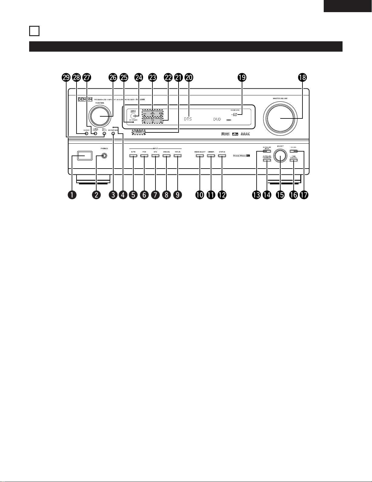
PART NAMES AND FUNCTIONS
Front Panel
• For details on the functions of these parts, refer to the pages given in parentheses ( ).
q
•
Power operation switch (for multiple voltage model) ………(37)
•
Power ON/STANDBY switch (for North America model)
w
Headphones jack (PHONES) ……………………………………(40)
e
MD/Tape monitor button (MD/TAPE MON) ……………………(38)
r
MD/Tape monitor indicator ………………………………………(38)
t
AUTO button ………………………………………………………(38)
y
PCM button ………………………………………………………(38)
u
DTS button …………………………………………………………(38)
i
ANALOG button……………………………………………………(38)
o
EXT. IN button ……………………………………………………(43)
!0
VIDEO SELECT button ……………………………………………(40)
!1
DIMMER button……………………………………………………(41)
!2
STATUS button ……………………………………………………(41)
!3
SURROUND MODE button ………………………………………(45)
!4
SURROUND PARAMETER button ………………………………(50)
!5
SELECT knob ………………………………………………………(40)
!6
TONE CONTROL button …………………………………………(40)
!7
CH. VOL button ……………………………………………………(44)
!8
MASTER VOLUME control ………………………………………(39)
!9
Master volume indicator (VOLUME LEVEL) ……………………(39)
@0
Display
@1
Surround speaker system indicators
(SURROUND SPEAKER A/B)
@2
INPUT indicators …………………………………………………(39)
@3
SIGNAL indicator …………………………………………………(39)
@4
Remote control sensor (REMOTE SENSOR) …………………(29)
@5
Power indicator ……………………………………………………(37)
@6
FUNCTION knob …………………………………………………(38)
@7
TUNING/PRESET button …………………………………………(55)
@8
SOURCE selector button …………………………………………(38)
@9
REC/MULTI selector button ………………………………………(41)
DVD
START LEARNED/TX
SPEAKER
TUNING
BAND
TITLE
MENU/GUIDE
MODE
MEMORY
USE/LEARN T.TONE MULTI DVD
SET UP
RETURN
STATUS
DISPLAY
ON SCREEN
DOLBY / DTS
SURROUND
DIRECT
DSP SIMULATION
5CH STEREO STEREO
INPUT MODE
ANALOG EXT.IN
MUTING
MASTER VOL.
VOLUME DISC SKIP+
SYSTEM CALL POWER
VDP TUNER SHIFT
TV/DBS PHONO
VCR-1 CD
MD / TAPE
CHANNEL
VCR-2/V.AUX
TV/VCR
AVR/AVC VIDEO DVD TV
AUDIO
VDP VCR
CD
MD
MULTI
DECK
SYSTEM
SETUP
SURROUND
PARAMETER
CH SELECT
SELECT
RC-860
123
4
SET
A / B
CALL OFF
ENTER
ON / SOURCE
56
789
+10
0
OUTPUT
16
ENGLISH
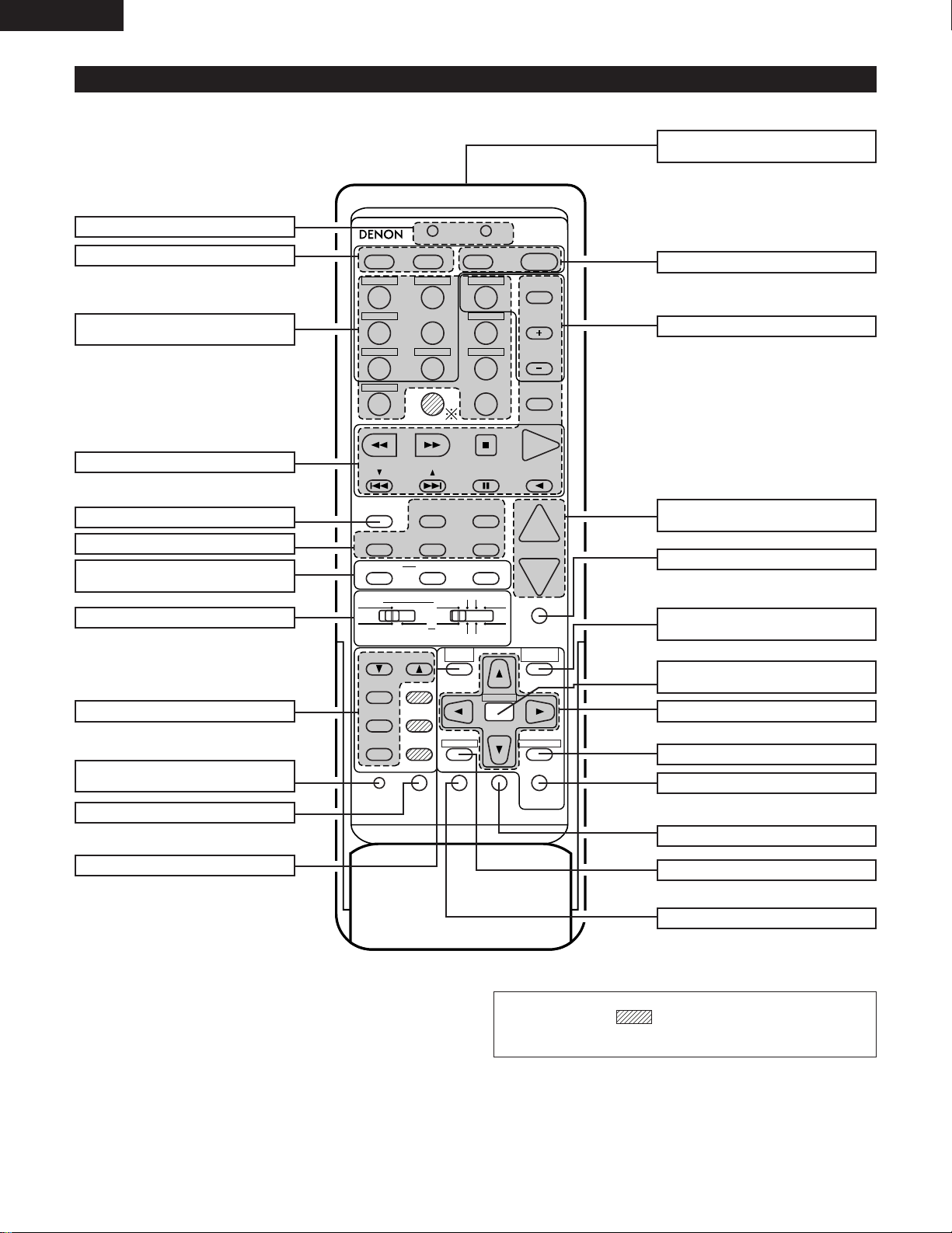
Remote control unit
• For details on the functions of these parts, refer to the pages given in parentheses ( ).
LEDs (indicators) …………………………….(34)
SYSTEM CALL buttons ……………………..(35)
Input source selector
buttons …………………………………………..(38)
System buttons ………………………………(30)
SURR. SP SETTING button…………………(49)
Surround buttons …………………………..(49)
INPUT MODE selector
buttons …………………………………………..(38)
Mode selector switches…………………….(30)
Tuner system buttons ………………………(30)
USE/LEARN selector
button …………………………………………..(34)
Test tone button ………………………………(44)
SYSTEM SETUP button …………………….(17)
Remote control signal
transmitter ……………………………………..(29)
Power button ………………………………..(37)
Tuner buttons ………………………………..(53)
Master volume control
buttons …………………………………………..(39)
MUTING button………………………………..(40)
SURROUND PARAMETER
button …………………………………………..(49)
Channel select/enter
button …………………………………………..(17)
Cursor buttons ………………………………..(17)
ON SCREEN button …………………………(40)
DVD SETUP button …………………………(33)
STATUS button …………………………………(41)
Multi source button…………………………..(42)
OUTPUT button ………………………………(40)
NOTE
• The shaded buttons do not function with the AVR-3300. (Nothing
happens when they are pressed.)
The button indicated
*
, however, can be used with the learning function.
TUNING
BAND
TITLE
MENU/GUIDE
MODE
MEMORY
USE/LEARN T.TONE MULTI
RETURN
DVD
SET UP
STATUS
DISPLAY
ON SCREEN
MUTING
AVR/AVC VIDEO DVD TV
AUDIO
VDP VCR
CDMDMULTI
DECK
SYSTEM
SETUP
SURROUND
PARAMETER
CH SELECT
SELECT
ENTER
OUTPUT
17
ENGLISH
7
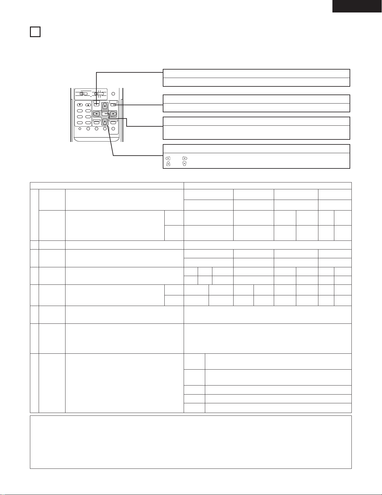
SETTING UP THE SYSTEM
• Once all connections with other AV components have been completed as described in “CONNECTIONS” (see pages 7 to 14), make the various
settings described below on the monitor screen using the AVR-3300’s on-screen display function.
These settings are required to set up the listening room’s AV system centered around the AVR-3300.
• Use the following buttons to set up the system:
SYSTEM SETUP button
Press this to display the system setup menu.
SURROUND PARAMETER button
Press this to display the surround parameter menu.
ENTER button
Press this to switch the display on the screen.
Also use this button to complete the setting on the screen.
CURSOR buttons
and : Use these to move the cursors (0 and 1) to the left and right on the screen.
and : Use these to move the cursors (• and ª) up and down on the screen.
• System setup items and default values (set upon shipment from the factory)
System setup Default settings
q
w
e
r
t
y
u
i
Speaker
Configuration
(Surround
Speaker
Setting)
Bass Output
Delay Time
Channel
Level
Digital Inputs
On Screen
Display
EXT. IN &
MULTI
Auto Tuner
Presets
Input the combination of speakers in your system and their
corresponding sizes (SMALL for regular speakers, LARGE for full-size,
full-range) to automatically set the composition of the signals output
from the speakers and the frequency response.
Use this function when using multiple surround speaker
combinations for more ideal surround sound. Once the
combinations of surround speakers to be used for the
different surround modes are preset, the surround
speakers are selected automatically according to the
surround mode.
This selects the subwoofer speaker for playing deep bass signals.
This parameter is for optimizing the timing with which the audio
signals are produced from the speakers and subwoofer according to
the listening position.
This adjusts the volume of the signals output from the speakers and
subwoofer for the different channels in order to obtain optimum
effects.
This assigns the digital input jacks for the different input
sources.
This sets whether or not to display the on-screen display that appears
on the monitor screen when the controls on the remote control unit or
main unit are operated (from MONITOR 1 outputs only).
Select one of these to use the external input terminals with 6- or 8channel inputs.
Multi-room output is not possible when the 8-channel input is
selected.
When the 6-channel input is selected, set the multi-room output’s
volume level.
FM stations are received automatically and stored in the memory.
Surround
mode
Input
source
Digital
Inputs
Surround
speaker
Front Sp. Center Sp. Surround Sp. Subwoofer
Small
5CH
STEREO
AA
Center
3.6 m (12 ft)
A—
Surround L & R —
3.0 m (10 ft) —
—
Small
DSP
SIMULA-
TION
6CH/8CH
EXT. IN
——
Ye sLarge
DOLBY/DTS
SURROUND
A
Bass Out = Subwoofer Only
Front & Subwoofer
3.6 m (12 ft)
Front L
0 dB
CD
COAXIAL
On Screen Display = ON
EXT. IN & MULTI = 6 CH IN & MULTI
MULTI VOL. LEVEL = 0 dB
A1 ~ A8
B1 ~ B8
C1 ~ C8
D1 ~ D8
E1 ~ E8
87.5/89.1/98.1/107.9/90.1/90.1/90.1/90.1 MHz (for North America model)
87.5/89.1/98.1/108.0/90.1/90.1/90.1/90.1 MHz
(for Multiple voltage and Taiwan R.O.C. models)
520/600/1000/1400/1500/1710 kHz/90.1/90.1 MHz (for North America mode)
522/603/999/1404/1611 kHz/90.1/90.1/90.1 MHz
(for Multiple voltage and Taiwan R.O.C. models)
90.1 MHz
90.1 MHz
90.1 MHz
Front R
0 dB
DVD
OPTICAL 1
Subwoofer
0 dB
VDP
OPTICAL 2
TV/DBS
OPTICAL 3
VCR-1
OFF
VCR-2/
V. AUX
——
OFF — —
Center
0 dB
Surround L
0 dB
Surround R
——
0 dB — —
NOTES:
• The on-screen display signals are not output from the color difference (component) video signal (MONITOR OUT) jacks.
• The on-screen display signals are output with priority to the S-VIDEO MONITOR OUT jack during playback of a video component. For example, if the TV monitor
is connected to both the AVR-3300’s S-Video and video monitor output jacks and signals are input to the AVR-3300 from a video source (VDP, etc.) connected to
both the S-Video and video input jacks, the on-screen display signals are output with priority to the S-Video monitor output. If you wish to output the signals to
the video monitor output jack, do not connect a cord to the S-VIDEO MONITOR OUT jack. (For details, see page 28.)
• The AVR-3300’s on-screen display function is designed for use with high resolution monitor TVs, so it may be difficult to read small characters on TVs with small
screens or low resolutions.
• The setup menu is not displayed when “HEADPHONE ONLY” is selected.
18
ENGLISH
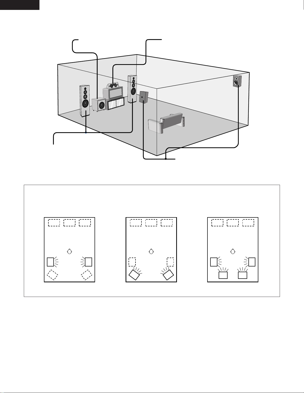
• Speaker system layout
Basic system layout
• The following is an example of the basic layout for a system consisting of six speaker systems and a television monitor:
Subwoofer
Center speaker system
Front speaker systems
Set these at the sides of the TV or screen with
their front surfaces as flush with the front of the
screen as possible.
Surround speaker systems
With the AVR-3300 it is also possible to use the surround speaker selector function to choose the best layout for a variety of sources and surround
modes.
• Surround speaker selector function
This function uses either or both of two systems of surround speakers (A and B) to achieve the optimum sound field for different sources.
The speaker settings (on or off for A only, B only or A+B) are stored in the memory for the different surround modes and are recalled
automatically when that surround mode is set.
Using A only
Using B only
Using both A and B (A+B)
Multi surround speaker mode
AA
BB
AABBAA
BB
19
ENGLISH
Before setting up the system
1
2
Check that all the connections are correct, then turn on the main unit’s power.
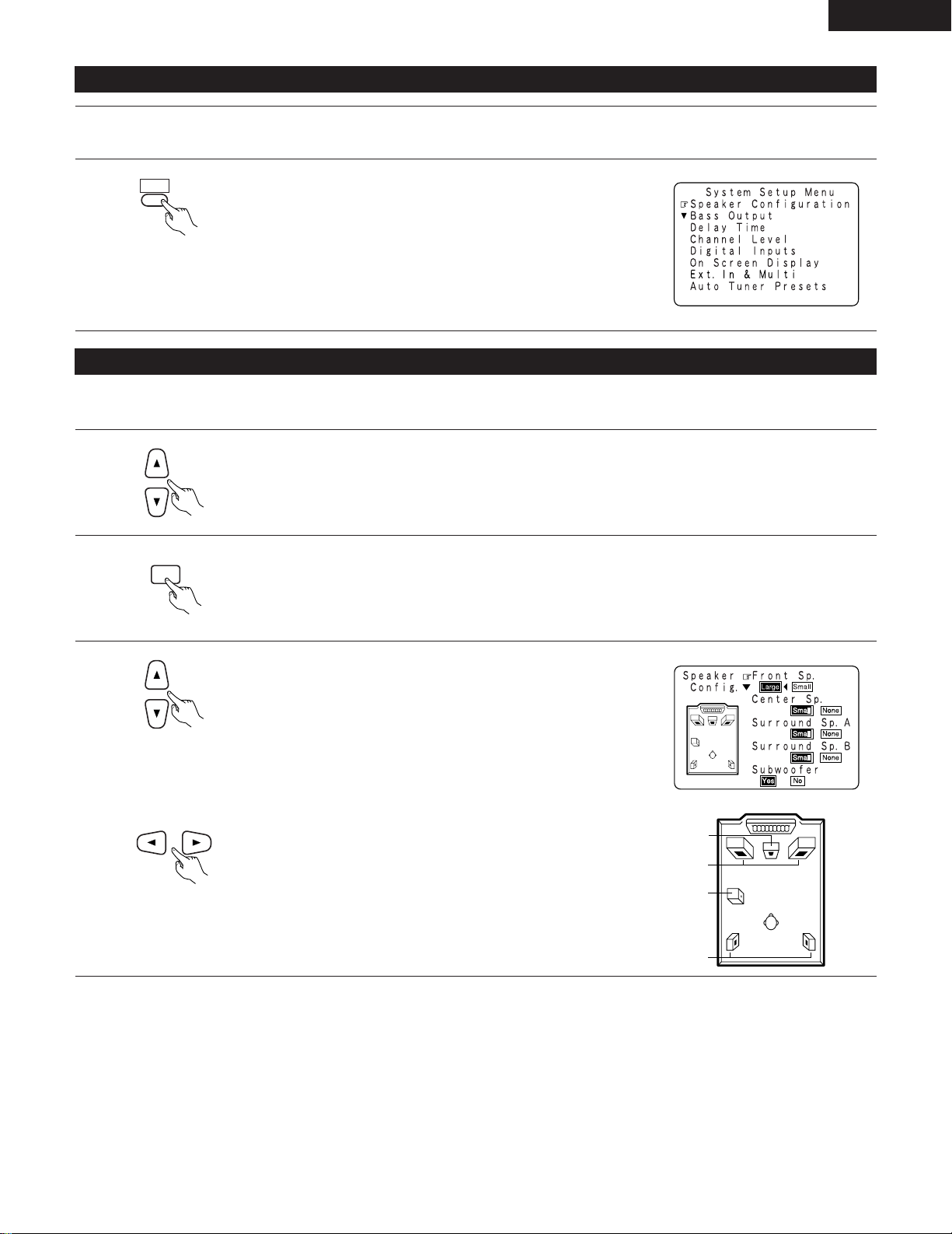
Display the System Setup Menu.
Setting the type of speakers
• The composition of the signals output from the different channels and the frequency response are adjusted automatically according to the
combination of speakers actually being used.
1
2
3
At the System Setup Menu select “Speaker Configuration”.
Switch to the speaker configuration screen.
Set whether or not speakers are connected and, if so, their size
parameters.
• To select the speaker
• To select the parameter
Center Sp.
Front Sp.
Subwoofer
Surround Sp.
Loading…
AV SURROUND RECEIVER
RÉCEPTEUR AUDIO-VIDÉO
AVR-3300
OPERATING INSTRUCTIONS
MODE D’EMPLOI
2 We greatly appreciate your purchase of the AVR-3300.
2 To be sure you take maximum advantage of all the features the AVR-3300 has to offer, read these instructions
carefully and use the set properly. Be sure to keep this manual for future reference should any questions or
problems arise.
2 Nous vous remercions de l’achat de l’AVR-3300.
2 Pour être sûr de profiter au maximum de toutes les caractéristiques qu’a à offrir l’AVR-3300, lire avec soin ces
instructions et bien utiliser l’appareil. Toujours conserver ce mode d’emploi pour s’y référer ultérieurement en
cas de question ou de problème.
FOR ENGLISH READERS PAGE 02 ~ PAGE 062
POUR LES LECTEURS FRANCAIS PAGE 2, 3, 63 ~ PAGE 120
-
Страница 1
DVD START LEARNED/TX SPEAKER TUNING BAND TITLE MENU/GUIDE MODE MEMORY USE/LEARN T.TONE MULTI OUTPUT SET UP RETURN STATUS DISPLAY ON SCREEN DOLBY / DTS SURROUND DIRECT DSP SIMULATION 5CH STEREO STEREO INPUT MODE ANALOG EXT.IN MUTING MASTER VOL. VOLUME DISC SKIP+ SYSTEM CALL POWER VDP TUNER SHIFT TV/DBS PHONO VCR-1 CD MD / TAPE CHANNEL VCR-2/V.AUX TV[…]
-
Страница 2
2 2 SAFETY PRECAUTIONS CAUTION: TO REDUCE THE RISK OF ELECTRIC SHOCK, DO NOT REMOVE COVER (OR BACK). NO USER- SERVICEABLE P ARTS INSIDE. REFER SER VICING TO QUALIFIED SERVICE PERSONNEL. The lightning flash with arrowhead symbol, within an equilateral triangle, is intended to alert the user to the presence of uninsulated “dangerous voltage” with[…]
-
Страница 3
3 2 NOTE ON USE / OBSERV A TIONS RELA TIVES A L ’UTILISA TION • Avoid high temperatures. Allow for sufficient heat dispersion when installed on a rack. • Eviter des températures élevées T enir compte d’une dispersion de chaleur suffisante lors de l’installation sur une étagère. • Handle the power cord carefully . Hold the plug when[…]
-
Страница 4
4 SAFETY INSTRUCTIONS 1. Read Instructions – All the safety and operating instructions should be read before the appliance is operated. 2. Retain Instructions – The safety and operating instructions should be retained for future reference. 3. Heed Warnings – All warnings on the appliance and in the operating instructions should be adhered to.[…]
-
Страница 5
5 ENGLISH 2 INTRODUCTION 2 ACCESSORIES Thank you for choosing the DENON A VR-3300 Digital Surround A / V receiver . This remarkable component has been engineered to provide superb surround sound listening with A V theater sources such as DVD, as well as providing outstanding high fidelity reproduction of your favorite music sources. As this product[…]
-
Страница 6
6 ENGLISH 3 CAUTIONS ON HANDLING 4 FEA TURES • Switching the input function when input jacks are not connected A clicking noise may be produced if the input function is switched when nothing is connected to the input jacks. If this happens, either turn down the MASTER VOLUME control or connect components to the input jacks. • Muting of PRE OUT […]
-
Страница 7
R L R L R INPUT OUTPUT LR L R OUTPUT L R L SWITCHED TOTAL 120W(1A.)MAX. AC 120V 60HZ AC OUTLETS SAME AS LINE-VOLTAGE SWITCHED 100W MAX. AC OUTLET OUTPUT OPTICAL COAXIAL OUTPUT OPTICAL IN IN OUT IN IN OUT SIGNAL GND DVD EXT. IN FREQ. STEP VDP TV / DBS VCR — 2/ V.AUX COAXIAL VCR — 2/ V.AUX MD/ TAPE MD/ TAPE VCR — 1 VCR — 1 OPT.-1 OPT.-2 OPT.-3 FR LOO[…]
-
Страница 8
IN IN OUT IN IN OUT SIGNAL GND DVD EXT. IN FREQ. STEP VDP TV / DBS VCR — 2/ V.AUX COAXIAL VCR — 2/ V.AUX MD/ TAPE MD/ TAPE VCR — 1 VCR — 1 OPT.-1 OPT.-2 OPT.-3 FR LOOP ANT. AM SW SR ER CD PHONO FL C SL EL DVD TV/DBS MONITOR Y YC B C B C R C R YC B C R COMPONENT VIDEO SPEAKER SY STEMS AUDIO DIGITAL C-VIDEO MONITOR S-VIDEO PRE OUT L L R R L R L R L R[…]
-
Страница 9
IN IN OUT IN IN OUT SIGNAL GND DVD EXT. IN FREQ. STEP VDP TV / DBS VCR — 2/ V.AUX COAXIAL VCR — 2/ V.AUX MD/ TAPE MD/ TAPE VCR — 1 VCR — 1 OPT.-1 OPT.-2 OPT.-3 FR LOOP ANT. AM SW SR ER CD PHONO FL C SL EL DVD TV/DBS MONITOR Y YC B C B C R C R YC B C R COMPONENT VIDEO SPEAKER SY STEMS AUDIO DIGITAL C-VIDEO MONITOR S-VIDEO PRE OUT L L R R L R L R L R[…]
-
Страница 10
IN IN OUT IN IN OUT SIGNAL GND DVD EXT. IN FREQ. STEP VDP TV / DBS VCR — 2/ V.AUX COAXIAL VCR — 2/ V.AUX MD/ TAPE MD/ TAPE VCR — 1 VCR — 1 OPT.-1 OPT.-2 OPT.-3 FR LOOP ANT. AM SW SR ER CD PHONO FL C SL EL DVD TV/DBS Y Y C B C R YC B C R COMPONENT VIDEO SPEAKER S AUDIO DIGITAL C-VIDEO MONITOR S-VIDEO PRE OU L R R L R L R L R L FM COAX. 75 FRONT CENT[…]
-
Страница 11
IN IN OUT DVD TV/DBS MONITOR Y YC B C B C R C R YC B C R COMPONENT VIDEO SPEAKER S YSTEMS PRE OUT L L R R L R L R B R L A FRONT FRONT CENTER SURROUND SURROUND SUB WOOFER CENTER SURROUND EFFECT MULTI/ Y Pr Pb B B VIDEO OUT Pr Y Pb COMPONENT VIDEO IN COMPONENT 11 ENGLISH Connecting a Video Component Equipped with Color Difference (Component — Y , R-Y[…]
-
Страница 12
12 ENGLISH Connecting the external input (EXT . IN) jacks • These input jacks are for inputting multi-channel audio signals in high definition MUSE 3-1 format, multi-channel audio signal s from an MPEG multi-channel decoder , or future multi-channel sound format, etc. • When making connections, also refer to the operating instructions of the ot[…]
-
Страница 13
13 ENGLISH Speaker system connections • Connect the speaker terminals with the speakers making sure that like polarities are matched ( ≈ with ≈ , √ with √ ). Mismatching of polarities will result in weak central sound, unclear orientation of the various instruments, and the sense of direction of the stereo being impaired. • When making […]
-
Страница 14
14 ENGLISH • This unit is equipped with a high-speed protection circuit. The purpose of this circuit is to protect the speakers under circumstances such as when the output of the power amplifier is inadvertently short-circuited and a large current flows, when the temperature surrounding the unit becomes unusually high, or when the unit is used at[…]
-
Страница 15
15 ENGLISH 6 P ART NAMES AND FUNCTIONS Front Panel • For details on the functions of these parts, refer to the pages given in parentheses ( ). q • Power operation switch (for multiple voltage model) ………(37) • Power ON/ST ANDBY switch (for North America model) w Headphones jack (PHONES) ……………………………………(40) e MD[…]
-
Страница 16
DVD START LEARNED/TX SPEAKER TUNING BAND TITLE MENU/GUIDE MODE MEMORY USE/LEARN T.TONE MULTI DVD SET UP RETURN STATUS DISPLAY ON SCREEN DOLBY / DTS SURROUND DIRECT DSP SIMULATION 5CH STEREO STEREO INPUT MODE ANALOG EXT.IN MUTING MASTER VOL. VOLUME DISC SKIP+ SYSTEM CALL POWER VDP TUNER SHIFT TV/DBS PHONO VCR-1 CD MD / TAPE CHANNEL VCR-2/V.AUX TV/VC[…]
-
Страница 17
TUNING BAND TITLE MENU/GUIDE MODE MEMORY USE/LEARN T.TONE MULTI RETURN DVD SET UP STATUS DISPLAY ON SCREEN MUTING AVR/AVC VIDEO DVD TV AUDIO VDP VCR CD MD MULTI DECK SYSTEM SETUP SURROUND PARAMETER CH SELECT SELECT ENTER OUTPUT 17 ENGLISH 7 SETTING UP THE SYSTEM • Once all connections with other A V components have been completed as described in […]
-
Страница 18
AA B B AA B B AA B B 18 ENGLISH • Speaker system layout Basic system layout • The following is an example of the basic layout for a system consisting of six speaker systems and a television monitor: Subwoofer Center speaker system Front speaker systems Set these at the sides of the TV or screen with their front surfaces as flush with the front […]
-
Страница 19
19 ENGLISH Before setting up the system 1 2 Check that all the connections are correct, then turn on the main unit’ s power . TITLE SYSTEM SETUP Display the System Setup Menu. Setting the type of speakers • The composition of the signals output from the different channels and the frequency response are adjusted automatically according to the co[…]
-
Страница 20
20 ENGLISH 4 ENTER Enter the setting. a) If no surround speakers are used (if “None” is set for both A and B): The System Setup Menu reappears. b) If both surround speakers A and B are used (if either “Large” or “Small” is set for both A and B): The surround speaker setting screen appears. c) If “None” is set for surround speakers A[…]
-
Страница 21
L 1 L 2 L 3 21 ENGLISH 2 3 4 ENTER ENTER Switch to the Bass Output screen. Select the bass signal playback mode. Enter the setting. The System Setup Menu reappears. NOTES: • In the Bass Output screen, you have the flexibility to choose how bass information is distributed to your speakers if you have large front left and right speakers and a subwo[…]
-
Страница 22
22 ENGLISH 2 3 4 5 6 ENTER Switch to the Delay T ime screen. Select the desired unit, meters or feet. Select (darken) the desired units, “Meters” or “Feet”. Once “Meters” or “Feet” is selected in step 3, the Delay T ime screen appears automatically . Select the speaker to be set. Set the distance between the center speaker and liste[…]
-
Страница 23
23 ENGLISH 7 ENTER Enter the setting. The System Setup Menu reappears. The A VR-3300 automatically sets the optimum surround delay time for the listening room. NOTE: • If the distance unit is changed after the delay time is set, the settings are reset to the factory default values (see page 17). Setting the channel level • Use this setting to a[…]
-
Страница 24
24 ENGLISH 6 7 8 Select “T est T one Start”. Select “Y es”. a. If the “Auto” mode is selected: T est tones are automatically emitted from the different speakers. The test tones are emitted from the different speakers in the following order , at 4-second intervals the first time and second time around, 2- second intervals the third time […]
-
Страница 25
25 ENGLISH Setting the digital inputs • This setting assigns the digital input jacks of the A VR-3300 for the different input sources. 1 2 3 4 ENTER ENTER At the System Setup Menu select “Digital Inputs”. Switch to the Digital Inputs screen. Select the digital input jack to be assigned to the input source. • T o select the input source • […]
-
Страница 26
26 ENGLISH 2 3 4 ENTER ENTER Switch to the On Screen Display screen. Select “ON” or “OFF”. Enter the setting. The System Setup Menu reappears. EXT . IN & MUL TI Set the number of input channels for the EXT . IN input. NOTES: • For multi-source playback, select the 6-channel input. • The multi-source function cannot be used when the […]
-
Страница 27
27 ENGLISH 4 5 6 7 ENTER ENTER Enter the setting. When “8CH IN” is selected, the “System Setup Menu” screen reappears. Select “V ol. Level”. Enter the setting. The “System Setup Menu” reappears. When “6CH IN & MUL TI” is selected, the screen switches to the “Multi V ol. Level” screen. NOTES: • When “0dB and “–40d[…]
-
Страница 28
28 ENGLISH ENTER 2 3 Press the ENTER button. The “Auto Preset Memory” screen appears. Use the CURSOR button to select “Y es”. “Search” flashes on the screen and searching begins. “Completed” appears once searching is completed. The display automatically switches to screen. * This completes system setup. Once these settings are made,[…]
-
Страница 29
29 ENGLISH 8 REMOTE CONTROL UNIT • The included remote control unit (RC-860) can be used to operate not only the A VR-3300 but other remote control compatible DENON components as well. Furthermore, it is equipped with a function for learning the control signals of remote control units of oth er manufacturers, so it can also be used to operate non[…]
-
Страница 30
30 ENGLISH Operating DENON audio components • T urn on the power of the different components before operating them. 1 2 3 Set mode switch 1 to “AUDIO (A VR/A VC)”. Set mode switch 2 to the position for the component to be operated. Operate the audio component. • For details, refer to the component’ s operating instructions. * While this r[…]
-
Страница 31
DENON A 31 ENGLISH Preset memory • DENON and other makes of components can be operated by setting the preset memory for your make of video component. Operation is not possible for some models, however . In this case use the learning function (see page 34) to store the remote control signals. • For instructions on clearing the presettings stored[…]
-
Страница 32
HIT ACHI A — — 32 ENGLISH “VCR” (DIRECT) MITSUBISHI A P ANASONIC A JVC (VICTOR) A SONY A PIONEER TOSHIBA A SANYO A SHARP A NEC A PHILIPS A RCA A GENERAL ELECTRIC A NAGNA VOX A (STEREO) — HIT ACHI B MITSUBISHI B P ANASONIC B JVC (VICTOR) B SONY B — TOSHIBA B SANYO B SHARP B NEC B PHILIPS B RCA B GENERAL ELECTRIC B NAGNA VOX B (EXT . IN) […]
-
Страница 33
33 ENGLISH Operating a video component stored in the preset memory 1 Set the slide switch to “VIDEO”. AVR/AVC VIDEO AUDIO 2 Set the slide switch to the component to be registered (VDP , VCR or TV). DVD TV VDP VCR CD MD MULTI DECK DVD START LEARNED/TX SPEAKER TUNING BAND TITLE MENU/GUIDE MODE MEMORY USE/LEARN T.TONE MULTI OUTPUT DVD SET UP RETUR[…]
-
Страница 34
34 ENGLISH Learning function • If your A V component is not a DENON product or it cannot be operated with the preset memory codesets, you can “teach” the A VR-3300’ s remote control to “learn” the codes from the component’ s original remote control. • The buttons that can be “learned” are the CD, DECK and MD system buttons (see […]
-
Страница 35
35 ENGLISH System call function • The included remote control unit is equipped with a system call function for transmitting multiple remote control signals when a single button is pressed (this is often referred to as a “macro” function). This function can be used to turn on the amplifier’ s power , select the input source, turn on the moni[…]
-
Страница 36
36 ENGLISH (3) Storing signals (4) Clearing system call settings DVD START LEARNED/TX SPEAKER TUNING BAND TITLE MENU/GUIDE MODE MEMORY USE/LEARN T.TONE MULTI DVD SET UP RETURN STATUS DISPLAY ON SCREEN DOLBY / DTS SURROUND DIRECT DSP SIMULATION 5CH STEREO STEREO INPUT MODE ANALOG EXT.IN MUTING MASTER VOL. VOLUME DISC SKIP+ SYSTEM CALL POWER VDP TUNE[…]
-
Страница 37
37 ENGLISH Clearing “learned” remote control signals and resetting the preset memory 1 Press the USE/LEARN selector button with the tip of a pen, etc., to set the learn mode. 2 T o clear “learned” remote control signals, set the slide switch to the position at which the signals were “learned”. T o clear the preset memory settings, set t[…]
-
Страница 38
38 ENGLISH Playing the input source 1 Select the input source to be played. FUNCTION Example: CD CD 8 (Main unit) (Remote control unit) * When the tape input (MD/T APE MON) is selected, the input indicator lights. * T o select the input source when REC MUL TI OUT or TUNING PRESET is selected, press the SOURCE button then operate the input function […]
-
Страница 39
LOCK SIGNAL DIGITAL LOCK SIGNAL DIGITAL LOCK SIGNAL DIGITAL ANALOG DIGIT AL DIGIT AL DIGIT AL ANALOG AUTO INPUT PCM DTS AUTO INPUT PCM DTS AUTO INPUT PCM DTS AUTO INPUT PCM DTS 39 ENGLISH PCM • Selecting the PCM mode Press the PCM button to switch to the PCM signal input. DTS • Selecting the DTS mode Press the DTS button to switch to the DTS si[…]
-
Страница 40
40 ENGLISH After starting playback [1] Adjusting the sound quality (TONE) The tone control function will not work in the direct mode. 1 The tone switches as follows each time the TONE CONTROL button is pressed. TONE CONTROL (Main unit) 2 With the name of the volume to be adjusted selected, turn the SELECT knob to adjust the level. NOTE: T o prevent[…]
-
Страница 41
41 ENGLISH Multi-source recording/playback [1] Playing one source while recording another (REC OUT mode) 1 Press the REC/MUL TI button. The display switches as follows each time the button is pressed. REC/ MULTI 2 With “RECOUT SOURCE” displayed, turn the FUNCTION knob to select the source you wish to record. • The “REC” indicator and the […]
-
Страница 42
The remote control unit’ s MUL TI button canbe operated at positions other than “MUL TI”. The multi source switches in order each time the multi button is pressed. 42 ENGLISH [3] Remote control unit operations during multi-source playback (selecting the input source) This operation is possible when “6CH IN & MUL TI” is selected at the[…]
-
Страница 43
RC-617 AVR-3300 RC-616 43 ENGLISH Multi-source and multi-zone playback MUL TI ROOM MUSIC ENTERT AINMENT SYSTEM • When the outputs of the MUL TI SOURCE AUDIO OUT terminals are wired and connected to integrated amplifiers installed in other rooms, different sources can be played in rooms other than the main room in which this unit and the playback […]
-
Страница 44
44 ENGLISH 10 SURROUND Before playing with the surround function • Before playing with the surround function, be sure to use the test tones to adjust the playback level from the different speakers. This adjustment can be performed with the system setup (see page 23) or from the remote control unit, as described below . • Adjusting with the remo[…]
-
Страница 45
45 ENGLISH Fader function • This function makes it possible to lower the volume of the front channels (FL, C and FR) or the rear channels (SL and SR) toge ther . Use it for example to adjust the balance of the sound from the different positions when playing multi-channel music sources. 1 Select “F ADER”. CH.VOL CH SELECT ENTER (Main unit) (Re[…]
-
Страница 46
46 ENGLISH Dolby Digital mode (only with digital input) and DTS Surround mode (only with digital input) 1 Select the input source. Playback with a digital input q Select an input source set to digital (COAXIAL/OPTICAL) (see page 25). FUNCTION VDP 2 (Main unit) (Remote control unit) w Set the input mode to “AUTO” or “DTS”. AUTO DTS INPUT MOD[…]
-
Страница 47
Surround parameters q CINEMA EQ. (Cinema Equalizer): The Cinema EQ function gently decreases the level of the extreme high frequencies, compensating for overly-bright sounding moti on picture soundtracks. Select this function if the sound from the front speakers is too bright. This function only works in the Dolby Pro Logic, Dolby Digital and DTS S[…]
-
Страница 48
48 ENGLISH 11 DSP SURROUND SIMULA TION • The A VR-3300 is equipped with a high performance DSP (Digital Signal Processor) which uses digital signal processing to synthetically recreate the sound field. One of six preset surround modes can be selected according to the program source and the parameters can be adjusted according to the conditions in[…]
-
Страница 49
49 ENGLISH DSP surround simulation 1 Select the surround mode for the input channel. • T o operate the surround mode and surround parameters from the remote control unit. The surround mode switches in the following order each time the DSP SIMULA TION button is pressed: 1 MONO MOVIE 1 ROCK ARENA 1 JAZZ CLUB 0 MA TRIX 0 VIDEO GAME 2 Display the sur[…]
-
Страница 50
50 ENGLISH • Operating the surround mode and surround parameters from the main unit‘s panel. 1 T urn the SELECT knob to select the surround mode. • When turned clockwise 1 DIRECT 1 STEREO 1 DOLBY/DTS 1 5CH STEREO 1 MONO MOVIE 0 MA TRIX 0 VIDEO GAME 0 JAZZ CLUB 0 ROCK ARENA • When turned counterclockwise 0 DIRECT 0 STEREO 0 DOLBY/DTS 0 5CH S[…]
-
Страница 51
51 ENGLISH T one control setting • Use the tone control setting to adjust the bass and treble as desired. • T o operate the tone control from the remote control unit. 1 Display the surround parameter screen on the monitor . * The screen for the selected surround mode appears. “TONE” cannot be selected in the Direct mode. DVD START LEARNED/T[…]
-
Страница 52
52 ENGLISH Surround parameters w ROOM SIZE: This sets the size of the sound field. There are five settings: “small”, “med.s” (medium-small), “medium”, “med.l” (medium-large) and “large”. “small” recreates a small sound field, “large” a large sound field. EFFECT LEVEL: This sets the strength of the surround effect. The le[…]
-
Страница 53
53 ENGLISH If tuning does not stop at the desired station, use to the “Manual tuning” operation. 1 Set the input function to “TUNER”. 2 Watching the display , press the BAND button to select the desired band (AM or FM). 3 Press the MODE button to set the auto tuning mode. 4 Press the TUNING UP or DOWN button. Auto tuning “Auto” appears […]
-
Страница 54
54 ENGLISH Checking the preset stations 1 Use the “Auto tuning” or “Manual tuning” operation to tune in the station to be preset in the memory . 2 Press the MEMORY button. 3 Press the SHIFT button and select the desired memory block (A to E). 4 Press the PRESET UP or DOWN button to select the desired preset channel (1 to 8). 5 Press the MEM[…]
-
Страница 55
55 ENGLISH Recalling preset stations • T o call out out preset stations from the remote control unit. 1 Watching the display , press the SHIFT button to select the preset memory block. (Remote control unit) 2 Watching the display , press the PRESET UP or DOWN button to select the desired preset channel. (Remote control unit) 13 LAST FUNCTION MEMO[…]
-
Страница 56
56 ENGLISH 15 TROUBLESHOOTING If a problem should arise,first check the following. 1. Are the connections correct ? 2. Have you operated the receiver according to the Operating Instructions ? 3. Are the speakers, turntable and other components operating property ? If this unit is not operating properly , check the items listed in the table below . […]
-
Страница 57
57 ENGLISH 16 ADDITIONAL INFORMA TION There are currently various types of multi-channel signals (signals or formats with more than two channels). 2 T ypes of multi-channel signals Dolby Digital, Dolby Pro Logic, DTS, high definition 3-1 signals (Japan MUSE Hi-Vision audio), DVD-Audio, SACD (Super Audio CD), MPEG multi- channel audio, etc. “Sourc[…]
-
Страница 58
58 ENGLISH Speaker setting examples Here we describe a number of speaker settings for different purposes. Use these examples as guides to set up your system accord ing to the type of speakers used and the main usage purpose. (1) Basic setting for primarily watching movies Use this setting if your main purpose is to listen to movie music and when us[…]
-
Страница 59
59 ENGLISH Surround The A VR-3300 is equipped with a digital signal processing circuit that lets you play program sources in the surround mode to ac hieve the same sense of presence as in a movie theater . Dolby Surround (1) Dolby Digital (Dolby Surround AC-3) Dolby Digital is the multi-channel digital signal format developed by Dolby Laboratories.[…]
-
Страница 60
60 ENGLISH (2) Dolby Pro Logic Dolby Pro Logic is a multi-channel signal playback system developed by Dolby Laboratories which decodes sources recorded in Dolby Surround into four channels: front left, center , front right and surround (the surround channel is monaural, but is played thro ugh two surround speakers). Here, “sources recorded in Dol[…]
-
Страница 61
61 ENGLISH System setup items and default values (set upon shipment from the factory) Surround modes and parameters C : Signal/adjustable D : Selected by speaker configuration setting B : T urned on or off by speaker configuration setting E : No signal/not adjustable (Note) When playing Dolby Digital Signal : –1 0 dB When playing DTS Digital Sign[…]
-
Страница 62
62 ENGLISH 17 SPECIFICA TIONS 2 Audio section • Power amplifier Rated output: Front: 105 W + 105 W (8 Ω /ohms, 20 Hz ~ 20 kHz with 0.05% T .H.D.) 140 W + 140 W (6 Ω /ohms, 1 kHz with 0.7% T .H.D.) Center: 105 W (8 Ω /ohms, 20 Hz ~ 20 kHz with 0.05% T .H.D.) 140 W (6 Ω /ohms, 1 kHz with 0.7% T .H.D.) Surround: 105 W + 105 W (8 Ω /ohms, 2[…]
DVD
START
LEARNED/TX
SPEAKER
TUNING
BAND
TITLE
MENU/GUIDE
MODE
MEMORY
USE/LEARN T.TONE
MULTI
OUTPUT
SET UP
RETURN
STATUS
DISPLAY
ON SCREEN
DOLBY / DTS
SURROUND
DIRECT
DSP SIMULATION
5CH STEREO
STEREO
INPUT MODE
ANALOG
EXT.IN
MUTING
MASTER VOL.
VOLUME
DISC SKIP+
SYSTEM CALL
POWER
VDP
TUNER
SHIFT
TV/DBS
PHONO
VCR-1
CD
MD / TAPE
CHANNEL
VCR-2/V.AUX
TV/VCR
AVR/AVC
VIDEO
DVD
TV
AUDIO
VDP
VCR
CD
MD
MULTI
DECK
SYSTEM
SETUP
SURROUND
PARAMETER
CH SELECT
SELECT
RC-860
1
2
3
4
SET
A / B
CALL
OFF
ENTER
ON / SOURCE
5
6
7
8
9
+10
0
MASTER VOLUME
FUNCTION
TUNING
PRESET
REC/
MULTI
SOURCE
AVR-3300
PRECISION AUDIO COMPONENT / AV SURROUND RECEIVER
MD/TAPE MON
VOLUME LEVEL
AUTO
LOCK
ON / STANDBY
PCM
DTS
SIGNAL
DIGITAL
INPUT
REMOTE
SENSOR
SURROUND
SPEAKER
A
B
PHONES
CH. VOL
SURROUND
MODE
SURROUND
PARAMETER
TONE
CONTROL
SELECT
INPUT
DIMMER
EXT. IN
ANALOG
DTS
AUTO
PCM
STATUS
VIDEO SELECT
B
AV SURROUND RECEIVER
RÉCEPTEUR AUDIO-VIDÉO
AVR-3300
OPERATING INSTRUCTIONS
MODE D’EMPLOI
2
We greatly appreciate your purchase of the AVR-3300.
2
To be sure you take maximum advantage of all the features the AVR-3300 has to offer, read these instructions
carefully and use the set properly. Be sure to keep this manual for future reference should any questions or
problems arise.
2
Nous vous remercions de l’achat de l’AVR-3300.
2
Pour être sûr de profiter au maximum de toutes les caractéristiques qu’a à offrir l’AVR-3300, lire avec soin ces
instructions et bien utiliser l’appareil. Toujours conserver ce mode d’emploi pour s’y référer ultérieurement en
cas de question ou de problème.
FOR ENGLISH READERS
PAGE
0
2 ~
PAGE
0
62
POUR LES LECTEURS FRANCAIS
PAGE
2, 3, 63 ~ PAGE 120