
AVR-3802
PRECISION AUDIO COMPONENT / AV SURROUND RECEIVER
OUTPUT
SIGNAL
DETECT
SURROUND
BACK CH
TUNING
PRESET
REC /
MULTI
6.1 / 7.1
SURROUND
SOURCE
ON / STANDBY
REMOTE
SENSOR
FUNCTION
SURROUND
SPEAKER
A
B
AUTO
PCM
DTS
SIGNAL
DIGITAL
INPUT
VOLUME LEVEL
MASTER VOLUME
SURROUND
MODE
SURROUND
PARAMETER
TONE
CONTROL
SELECT CH VOL
DIMMER
STATUS TONE DEFEAT
VIDEO SELECT
INPUT
EXT. IN
ANALOG
AUTO PCM DTS
PHONES
ON / STANDBY
1
2
3
456
789
+10
0
TV/
VCR
OFF
TV
CD
CDR/MD/TAPE RECEIVER
VCR DBS/CABLE
SKIP
SKIP
ENTER
MEMORY
VOLUME
CHANNEL
+
—
+
—
VDP DVD
POWER
REMOTE CONTROL UNIT
RC-883
ON /
SOURCE
TUNER
VDP
VCR-1 VCR-2/V.AUX
DVD
TV/DBS
CDR/TAPE
PHONO
CD
SURROUND
INPUT
OUTPUT
TEST
TONE
SPEAKER
6.1 / 7.1
SURROUND
5CH / 7CH
ANALOG
EXT.INMODE
CALL 2
BACKLIGHT
CALL 1
STEREO
STEREO
DOLBY/DTS
SURROUND
DSP
SIMU.
DISPLAY
SYSTEM CALL
DIRECT
RETURN
SETUP
MENU
SHIFT
SURR.
PARA.
OSD
A/B
MUTING
BAND MODE
TUNING
TUNING
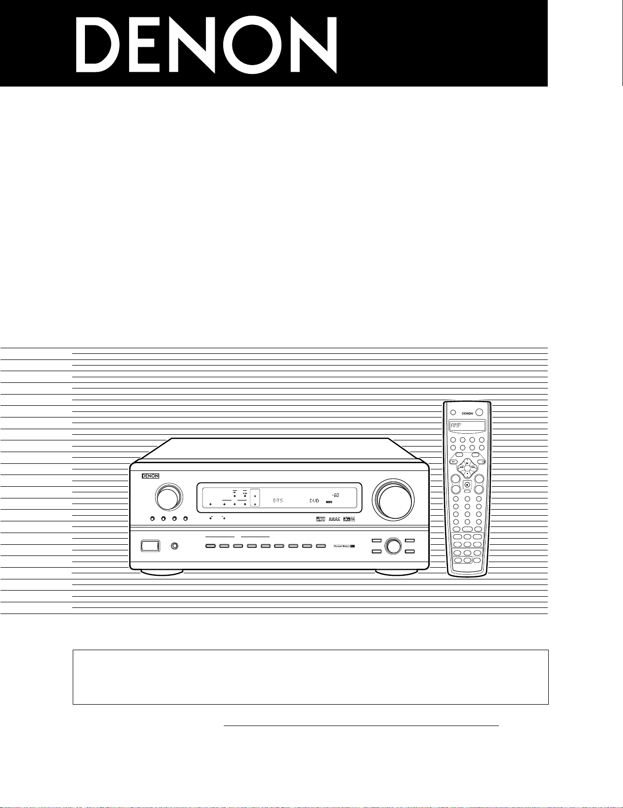
AV SURROUND RECEIVER
AVR-3802
OPERATING INSTRUCTIONS
2 We greatly appreciate your purchase of the AVR-3802.
2 To be sure you take maximum advantage of all the features the AVR-3802 has to offer, read these instructions
carefully and use the set properly. Be sure to keep this manual for future reference, should any questions or
problems arise.
“SERIAL NO.
PLEASE RECORD UNIT SERIAL NUMBER ATTACHED TO THE REAR OF THE
CABINET FOR FUTURE REFERENCE”
CAUTION:
TO REDUCE THE RISK OF ELECTRIC SHOCK, DO
NOT REMOVE COVER (OR BACK). NO USERSERVICEABLE PARTS INSIDE. REFER SERVICING
TO QUALIFIED SERVICE PERSONNEL.
The lightning flash with arrowhead symbol, within an
equilateral triangle, is intended to alert the user to the
presence of uninsulated “dangerous voltage” within
the product’s enclosure that may be of sufficient
magnitude to constitute a risk of electric shock to
persons.
The exclamation point within an equilateral triangle is
intended to alert the user to the presence of important
operating and maintenance (servicing) instructions in
the literature accompanying the appliance.
CAUTION
TO PREVENT ELECTRIC SHOCK, MATCH WIDE BLADE OF PLUG
TO WIDE SLOT, FULLY INSERT.
ATTENTION
POUR ÉVITER LES CHOCS ÉLECTRIQUES, INTERODUIRE LA
LAME LA PLUS LARGE DE LA FICHE DANS LA BORNE
CORRESPONDANTE DE LA PRISE ET POUSSER JUSQU’ AU
FOND.
This device complies with Part 15 of the FCC Rules. Operation is subject to
the following two conditions: (1) This device may not cause harmful
interference, and (2) this device must accept any interference received,
including interference that may cause undesired operation.
This Class B digital apparatus meets all requirements of the Canadian
Interference-Causing Equipment Regulations.
Cet appareil numérique de la classe B respecte toutes les exigences du
Règlement sur le matériel brouilleur du Canada.
WARNING:
TO PREVENT FIRE OR SHOCK HAZARD, DO NOT EXPOSE
THIS APPLIANCE TO RAIN OR MOISTURE.
2
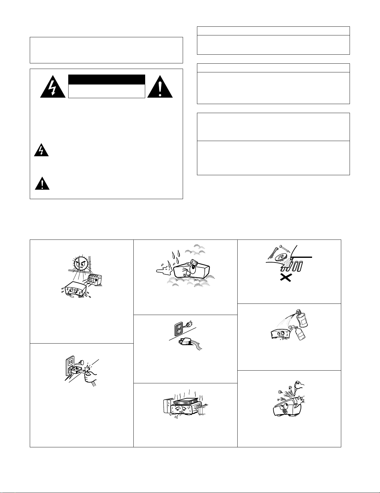
NOTE ON USE / OBSERVATIONS RELATIVES A L’UTILISATION
• Avoid high temperatures.
Allow for sufficient heat dispersion when
installed on a rack.
• Eviter des températures élevées
Tenir compte d’une dispersion de chaleur
suffisante lors de l’installation sur une étagère.
• Handle the power cord carefully.
Hold the plug when unplugging the cord.
• Manipuler le cordon d’alimentation avec
précaution.
Tenir la prise lors du débranchement du cordon.
• Keep the set free from moisture, water, and
dust.
• Protéger l’appareil contre l’humidité, l’eau et
lapoussière.
• Unplug the power cord when not using the set
for long periods of time.
• Débrancher le cordon d’alimentation lorsque
l’appareil n’est pas utilisé pendant de longues
périodes.
* (For sets with ventilation holes)
• Do not obstruct the ventilation holes.
• Ne pas obstruer les trous d’aération.
• Do not let foreign objects in the set.
• Ne pas laisser des objets étrangers dans
l’appareil.
• Do not let insecticides, benzene, and thinner
come in contact with the set.
• Ne pas mettre en contact des insecticides, du
benzène et un diluant avec l’appareil.
• Never disassemble or modify the set in any
way.
• Ne jamais démonter ou modifier l’appareil
d’une manière ou d’une autre.
CAUTION
RISK OF ELECTRIC SHOCK
DO NOT OPEN
3
SAFETY INSTRUCTIONS
1. Read Instructions – All the safety and operating instructions
should be read before the appliance is operated.
2. Retain Instructions – The safety and operating instructions
should be retained for future reference.
3. Heed Warnings – All warnings on the appliance and in the
operating instructions should be adhered to.
4. Follow Instructions – All operating and use instructions
should be followed.
5. Water and Moisture – The appliance should not be used
near water – for example, near a bathtub, washbowl,
kitchen sink, laundry tub, in a wet basement, or near a
swimming pool, and the like.
6. Carts and Stands – The appliance should be used only with
a cart or stand that is recommended by the manufacturer.
6A. An appliance and cart
combination should be
moved with care.
Quick stops, excessive
force, and uneven
surfaces may cause
the appliance and cart
combination to overturn.
7. Wall or Ceiling Mounting – The appliance should be
mounted to a wall or ceiling only as recommended by the
manufacturer.
8. Ventilation – The appliance should be situated so that its
location or position does not interfere with its proper
ventilation. For example, the appliance should not be
situated on a bed, sofa, rug, or similar surface that may
block the ventilation openings; or, placed in a built-in
installation, such as a bookcase or cabinet that may impede
the flow of air through the ventilation openings.
9. Heat – The appliance should be situated away from heat
sources such as radiators, heat registers, stoves, or other
appliances (including amplifiers) that produce heat.
10. Power Sources – The appliance should be connected to a
power supply only of the type described in the operating
instructions or as marked on the appliance.
11. Grounding or Polarization – Precautions should be taken so
that the grounding or polarization means of an appliance is
not defeated.
12. Power-Cord Protection – Power-supply cords should be
routed so that they are not likely to be walked on or pinched
by items placed upon or against them, paying particular
attention to cords at plugs, convenience receptacles, and
the point where they exit from the appliance.
14. Cleaning – The appliance should be cleaned only as
recommended by the manufacturer.
15. Power Lines – An outdoor antenna should be located away
from power lines.
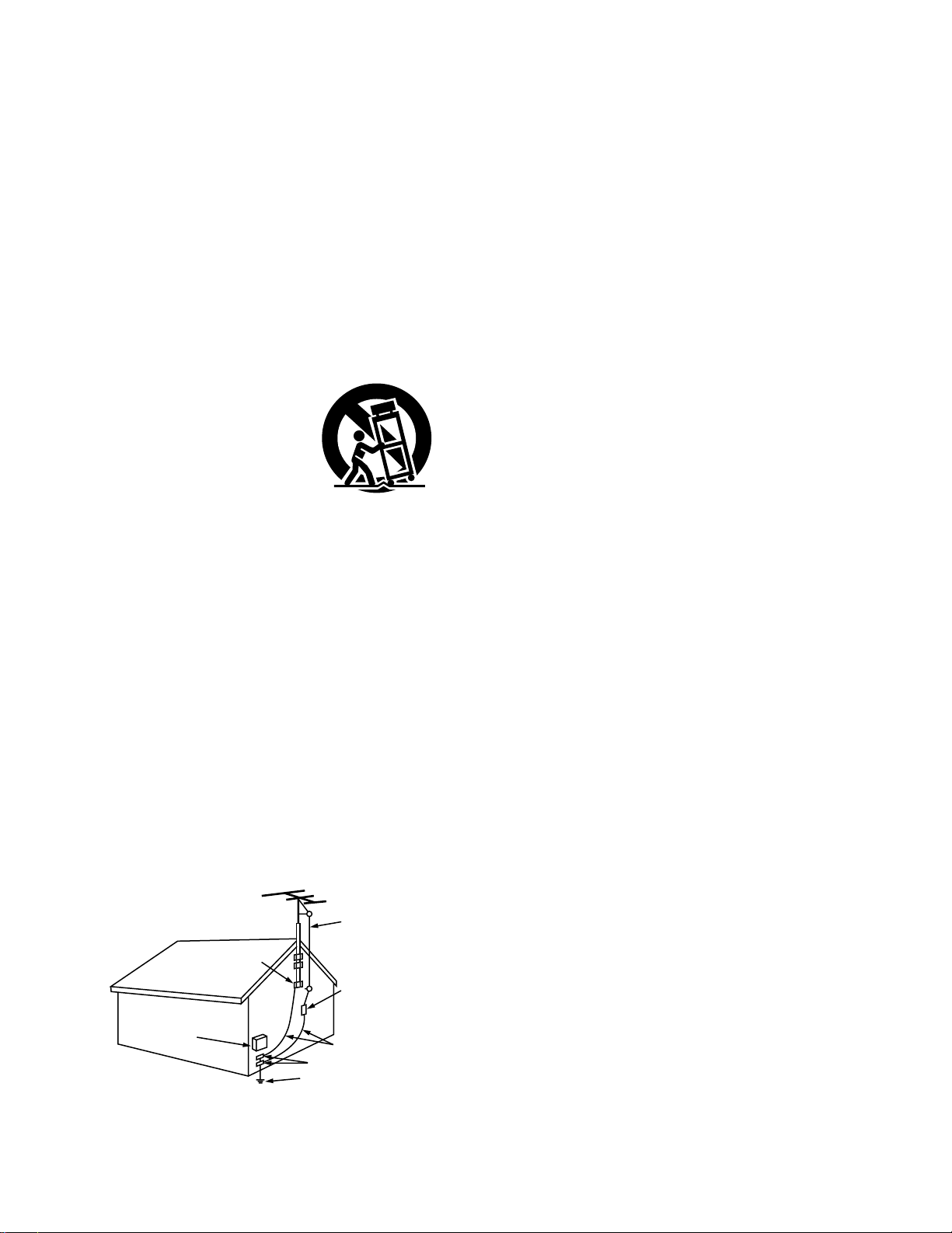
16. Outdoor Antenna Grounding – If an outside antenna is
connected to the receiver, be sure the antenna system is
grounded so as to provide some protection against voltage
surges and built-up static charges. Article 810 of the
National Electrical Code, ANSI/NFPA 70, provides
information with regard to proper grounding of the mast and
supporting structure, grounding of the lead-in wire to an
antenna-discharge unit, size of grounding conductors,
location of antenna-discharge unit, connection to grounding
electrodes, and requirements for the grounding electrode.
See Figure A.
17. Nonuse Periods – The power cord of the appliance should
be unplugged from the outlet when left unused for a long
period of time.
18. Object and Liquid Entry – Care should be taken so that
objects do not fall and liquids are not spilled into the
enclosure through openings.
19. Damage Requiring Service – The appliance should be
serviced by qualified service personnel when:
A. The power-supply cord or the plug has been damaged; or
B. Objects have fallen, or liquid has been spilled into the
appliance; or
C. The appliance has been exposed to rain; or
D. The appliance does not appear to operate normally or
exhibits a marked change in performance; or
E. The appliance has been dropped, or the enclosure
damaged.
20. Servicing – The user should not attempt to service the
appliance beyond that described in the operating
instructions. All other servicing should be referred to
qualified service personnel.
FIGURE A
EXAMPLE OF ANTENNA GROUNDING
AS PER NATIONAL
ELECTRICAL CODE
ANTENNA
LEAD IN
WIRE
GROUND
CLAMP
ELECTRIC
SERVICE
EQUIPMENT
ANTENNA
DISCHARGE UNIT
(NEC SECTION 810-20)
GROUNDING CONDUCTORS
(NEC SECTION 810-21)
GROUND CLAMPS
POWER SERVICE GROUNDING
ELECTRODE SYSTEM
(NEC ART 250, PART H)
NEC — NATIONAL ELECTRICAL CODE
4
2
INTRODUCTION
2
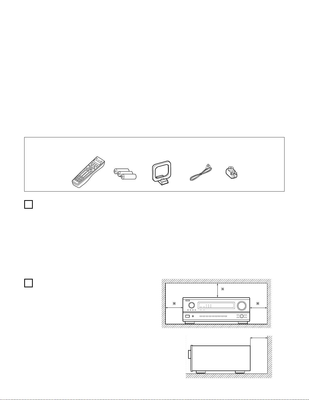
ACCESSORIES
Thank you for choosing the DENON Digital Surround A / V receiver. This remarkable component has been engineered to provide superb surround
sound listening with home theater sources such as DVD, as well as providing outstanding high fidelity reproduction of your favorite music sources.
As this product is provided with an immense array of features, we recommend that before you begin hookup and operation that you review the
contents of this manual before proceeding.
TABLE OF CONTENTS
z Before Using …………………………………………………………………………………..4
x Cautions on Installation …………………………………………………………………….4
c Cautions on Handling ……………………………………………………………………….5
v Features …………………………………………………………………………………………5
b Connections ………………………………………………………………………………6~13
n Part Names and Functions…………………………………………………………14, 15
m Setting up the system ………………………………………………………………16~28
, Remote Control Unit…………………………………………………………………29~40
. Operation ………………………………………………………………………………..41~48
⁄0 Surround …………………………………………………………………………………49~53
⁄1 DSP Surround Simulation ………………………………………………………….54~59
⁄2 Listening to the Radio……………………………………………………………….60~62
⁄3 Last Function Memory ……………………………………………………………………62
⁄4 Initialization of the Microprocessor …………………………………………………..62
⁄5 Troubleshooting……………………………………………………………………………..63
⁄6 Additional Information……………………………………………………………….64~72
⁄7 Specifications ………………………………………………………………………………..73
Check that the following parts are included in addition to the main unit:
q Operating instructions…..1 w Warranty ( for North America model only )………………..1 e Service station list………..1 r Remote control unit
t R6P/AA batteries ………….3 y AM loop antenna………………1 u FM indoor antenna…1 i FM antenna adaptor……..1 (RC-883)…………………1
1
2
BEFORE USING
CAUTIONS ON INSTALLATION
Pay attention to the following before using this unit:
• Moving the set
To prevent short circuits or damaged wires in the connection cords,
always unplug the power cord and disconnect the connection cords
between all other audio components when moving the set.
• Before turning the power switch on
Check once again that all connections are proper and that there are
not problems with the connection cords. Always set the power
switch to the standby position before connecting and disconnecting
connection cords.
Noise or disturbance of the picture may be generated if this unit or
any other electronic equipment using microprocessors is used near a
tuner or TV.
If this happens, take the following steps:
• Install this unit as far as possible from the tuner or TV.
• Set the antenna wires from the tuner or TV away from this unit’s
power cord and input/output connection cords.
• Noise or disturbance tends to occur particularly when using indoor
antennas or 300 Ω/ohms feeder wires. We recommend using
outdoor antennas and 75 Ω/ohms coaxial cables.
For heat dispersal, leave at least 4 inch/10 cm of space between
the top, back and sides of this unit and the wall or other
components.
• Store this instructions in a safe place.
After reading, store this instructions along with the warranty in a
safe place.
• Note that the illustrations in this instructions may differ from
the actual set for explanation purposes.
4 inch/10 cm or more
4 inch/10 cm or more
Wall
B

5
3
CAUTIONS ON HANDLING
4
FEATURES
• Switching the input function when input jacks are not
connected
A clicking noise may be produced if the input function is switched
when nothing is connected to the input jacks. If this happens, either
turn down the MASTER VOLUME control or connect components
to the input jacks.
• Muting of PRE OUT jacks, HEADPHONE jack and SPEAKER
terminals
The PRE OUT jacks, HEADPHONE jacks and SPEAKER terminals
include a muting circuit. Because of this, the output signals are
greatly reduced for several seconds after the power switch is
turned on or input function, surround mode or any other-set-up is
changed. If the volume is turned up during this time, the output will
be very high after the muting circuit stops functioning. Always wait
until the muting circuit turns off before adjusting the volume.
• Whenever the power switch is in the STANDBY state, the
apparatus is still connected on AC line voltage.
Please be sure to unplug the cord when you leave home for,
say, a vacation.
1. Digital Surround Sound Decoding
Featuring 32 bit high speed DSP, operating entirely in digital
domain, surround sound from digital sources such as DVD, LD,
DTV and satellite are faithfully re-created.
2. Dolby Pro Logic II decoder
Dolby Pro Logic II is a new format for playing multichannel audio
signals that offers improvements over conventional Dolby Pro
Logic. It can be used to decode not only sources recorded in Dolby
Surround but also regular stereo sources into five channels (front
left/right, center and surround left/right). In addition, various
parameters can be set according to the type of source and the
contents, so you can adjust the sound field with greater precision.
3. Dolby Digital
Using advanced digital processing algorithms, Dolby Digital
provides up to 5.1 channels of wide-range, high fidelity surround
sound. Dolby Digital is the default digital audio delivery system for
North American DVD and DTV.
4. DTS (Digital Theater Systems)
DTS provides up to 5.1 channels of wide-range, high fidelity
surround sound, from sources such as laser disc, DVD and
specially-encoded music discs.
5. DTS-ES Extended Surround and DTS Neo:6
The AVR-3802 is compatible with DTS-ES Extended Surround, a new
multi-channel format developed by Digital Theater Systems Inc.
The AVR-3802 is also compatible with DTS Neo:6, a surround mode
allowing 6.1-channel playback of regular stereo sources.
6. Wide screen mode for a 7.1-channel sound even with
5.1-channel sources
DENON has developed a wide screen mode with a new design
which recreates the effects of the multi surround speakers in
movie theaters. The result is 7.1-channel sound taking full
advantage of surround back speakers, even with Dolby Pro Logic
or Dolby Digital/DTS 5.1-channel signals.
7. 24 bit D/A Conversion
All six channels, including the five main channels and the low
frequency effects (LFE) channel benefit from reference, for
optimum high fidelity reproduction of music and movie
soundtracks.
8. Dual Surround Speaker Mode
Provides for the first time the ability to optimize surround sound
reproduction using two different types of surround sound speakers
as well as two different surround speaker positions:
(1) Movie Surround
Motion picture soundtracks use the surround channel(s) to
provide the ambient elements of the acoustic environment they
want the audience to realize. This is best accomplished by the
use of specially-designed surround speakers that offer a wide
diffusion pattern (bipolar dispersion) or by using surround
speakers that provide broad dispersion with a minimum of onaxis localization (dipolar dispersion). Side wall mounting (closer
to the ceiling) of the surround speakers provides the greatest
envelopment, minimizing localization of direct sound from the
speakers.
(2) Music Surround
With full range discrete surround channels, as well as three
discrete full range front channels, digital formats such as Dolby
and DTS offer thrilling surround sound music listening.
Producers of multi-channel discrete digital music recordings
almost always favor the use of direct radiating (monopolar)
surround speakers, placed in the rear corners of the room,
since that is how they configure their studios during the
mixing/creation process.
The DENON AVR-3802 provides the ability to connect two
different sets of surround speakers, and place them in the
appropriate locations in your AV theater room, so that you can
enjoy both movie soundtracks and music listening, with
optimum results and no compromise.
9. Component Video Switching
In addition to composite video and “S” video switching, the AVR3802 provides 2 sets of component video (Y, P
B/CB, PR/CR) inputs
for the DVD and TV/DBS inputs, and one set of component video
outputs to the television, for superior picture quality.
10.Video Select Function
Allow you to watch one source (visual) while listening to another
source (audio).
11.Future Sound Format Upgrade Capability via Eight Channel
Inputs & Outputs
For future multi-channel audio format(s), the AVR-3802 is provided
with 7.1 channel (seven main channels, plus one low frequency
effects channel) inputs, along with a full set of 7.1 channel pre-amp
outputs, controlled by the 8 channel master volume control. This
assures future upgrade possibilities for any future multi-channel
sound format.
RLR
L
R
INPUT OUTPUT
LRL
R
OUTPUT
L
R
L
INPUT
OPTICAL COAXIAL
OUTPUT
OPTICAL
L
R
L
R
L
R
L
R
OUTPUT
DIGITAL AUDIODIGITAL AUDIO
DIGITAL AUDIODIGITAL AUDIO
B
B
5
CONNECTIONS
• Do not plug in the AC cord until all connections have been
completed.
• Be sure to connect the left and right channels properly (left with
left, right with right).
• Insert the plugs securely. Incomplete connections will result in the
generation of noise.
• Use the AC OUTLETS for audio equipment only. Do not use
them for hair driers, etc.
• Note that binding pin plug cords together with AC cords or placing
them near a power transformer will result in generating hum or
other noise.
• Noise or humming may be generated if a connected audio
equipment is used independently without turning the power of this
unit on. If this happens, turn on the power of the this unit.
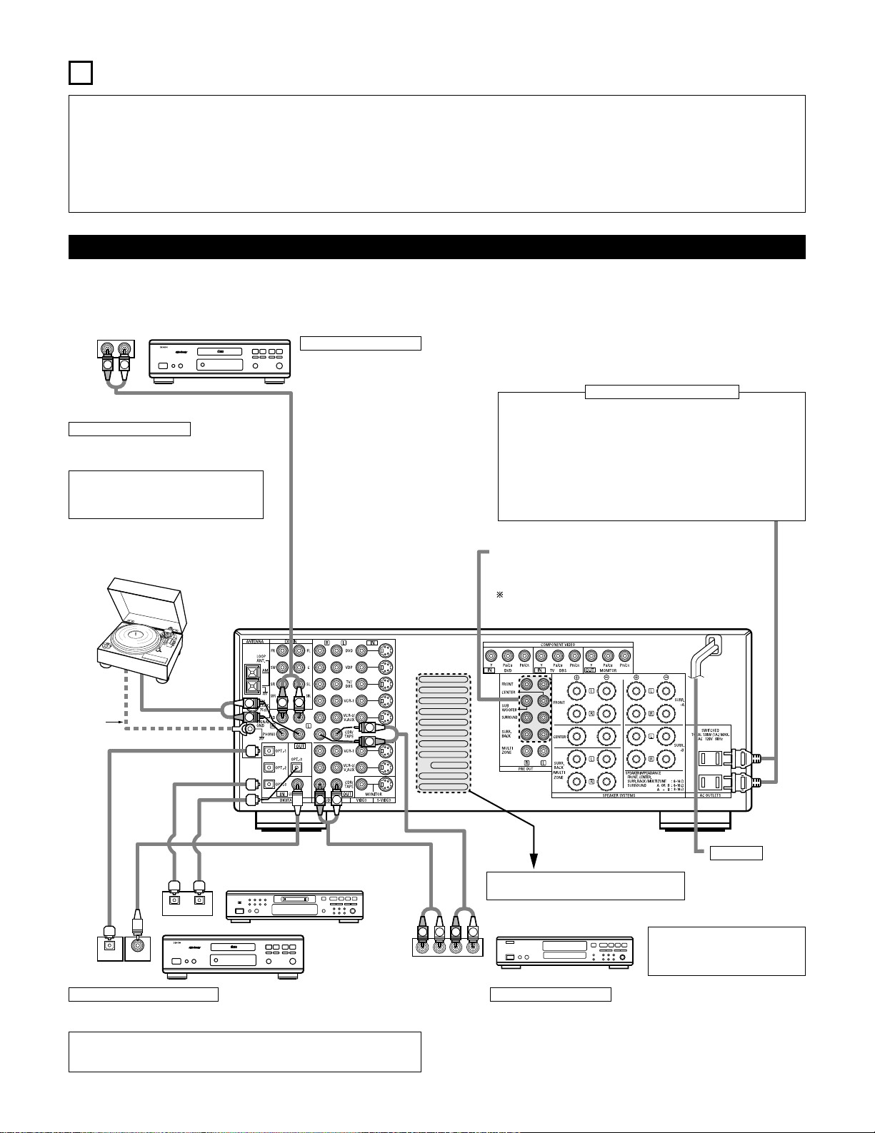
Connecting the audio components
• When making connections, also refer to the operating instructions of the other components.
The power to these outlets is turned on and off when the power is switched between on and standby from the remote control unit or power
switch.
CD player
Connecting a CD player
Connect the CD player’s analog output
jacks (ANALOG OUTPUT) to this unit’s CD
jacks using pin plug cords.
Connecting a turntable
Connect the turntable’s output cord to the AVR3802’s PHONO jacks, the L (left) plug to the L jack,
the R (right) plug to the right jack.
NOTE:
This unit cannot be used with MC cartridges
directly. Use a separate head amplifier or step-up
transformer.
If humming or other noise is generated when the
ground wire is connected, disconnect the ground
wire.
Turntable
(MM cartridge)
Ground
wire
Connecting the pre-out jacks
Use these jacks if you wish to connect external power amplifier(s) to
increase the power of the front, center and surround sound channels, or
for connection to powered loudspeakers.
To use Surround back with one speaker, connect the speaker to
SURR. BACK L CH.
AC OUTLETS
• SWITCHED
(total capacity – 120 W (1 A.))
The power to these outlets is turned on and off in conjunction with the
POWER operation switch on the main unit, and when the power is switched
between on and standby from the remote control unit.
No power is supplied from these outlets when this unit’s power is at standby.
Never connect equipment whose total capacity is above 120 W (1 A.).
NOTE:
Only use the AC OUTLETS for audio equipment. Never use them for hair
driers, TVs or other electrical appliances.
Connecting the AC OUTLETS
AC CORD
AC 120 V, 60 Hz
Connecting a tape deck
Connections for recording:
Connect the tape deck’s recording input jacks (LINE IN or REC) to this unit’s tape
recording (CDR/TAPE OUT) jacks using pin plug cords.
Connections for playback:
Connect the tape deck’s playback output jacks (LINE OUT or PB) to this unit’s tape
playback (CDR/TAPE IN) jacks using pin plug cords.
CD recorder or Tape deck
Route the connection cords, etc., in such a way
that they do not obstruct the ventilation holes.
MD recorder, CD recorder or other component
equipped with digital input/output jacks
CD player or other
component equipped
with digital output jacks
Connecting the DIGITAL jacks
Use these for connections to audio equipment with digital output. Refer to page 25 for
instructions on setting this terminal.
NOTES:
• Use 75 Ω/ohms cable pin cords for coaxial connections.
• Use optical cables for optical connections, removing the cap before connecting.
NOTE:
If humming noise is generated by a
tape deck, etc., move the tape deck
away.
IN
VIDEO
R
L
R OUT IN
AUDIO
VIDEO
OUT IN
LRL
RLR
L
R OUT IN
AUDIO
VIDEO
OUT IN
LRL
R
L
R
L
R OUT
VIDEO
OUT
L
AUDIO
L
R
R OUT
VIDEO
OUT
L
AUDIO
L
R
R
L
R
L
R
L
R
L
RL
B
B
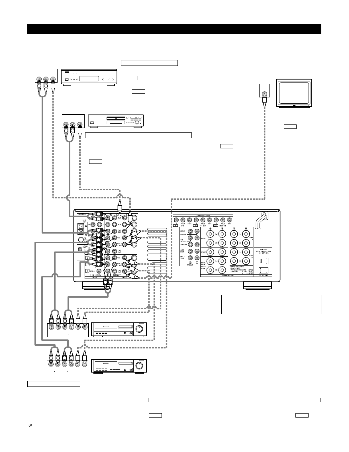
Connecting video components
• To connect the video signal, connect using a 75 Ω/ohms video signal cable cord. Using an improper cable can result in a drop in video quality.
• When making connections, also refer to the operating instructions of the other components.
TV or DBS tuner
Connecting a TV/DBS tuner
TV/DBS
• Connect the TV’s or DBS tuner’s video output jack (VIDEO OUTPUT) to the
(yellow) TV/DBS IN jack using a 75 Ω/ohms video coaxial pin plug
cord.
• Connect the TV’s or DBS tuner’s audio output jacks (AUDIO OUTPUT) to
the TV/DBS IN jacks using pin plug cords.
AUDIO
VIDEO
DVD player or video disc player (VDP), etc.
Connecting a DVD player or a video disc player (VDP)
DVD
• Connect the video disc player’s video output jack (VIDEO OUTPUT) to the (yellow) DVD IN
jack using a 75 Ω/ohms video coaxial pin plug cord.
• Connect the video disc player’s analog audio output jacks (ANALOG AUDIO OUTPUT) to the
DVD IN jacks using pin plug cords.
• A VDP can be connected to the VDP jacks in the same way.
• It is also possible to connect a video disc player, DVD player, video camcorder, game machine, etc.,
to the VCR-2/V.AUX jacks.
AUDIO
VIDEO
Monitor TV
MONITOR OUT
• Connect the TV’s video
input jack (VIDEO INPUT) to
the MONITOR
OUT jack using a 75
Ω/ohms video coaxial pin
plug cord.
VIDEO
Note on connecting the digital input jacks
• Only audio signals are input to the digital input jacks.
For details, see page 6.
Video deck 2
Video deck 1
Connecting a video decks
• There are two sets of video deck (VCR) jacks, so two video decks can be connected for simultaneous recording or video copying.
Video input/output connections:
• Connect the video deck’s video output jack (VIDEO OUT) to the (yellow) VCR-1 IN jack, and the video deck’s video input jack (VIDEO IN) to the
(yellow) VCR-1 OUT jack using 75 Ω/ohms video coaxial pin plug cords.
Connecting the audio output jacks
• Connect the video deck’s audio output jacks (AUDIO OUT) to the VCR-1 IN jacks, and the video deck’s audio input jacks (AUDIO IN) to the VCR-1
OUT jacks using pin plug cords.
Connect the second video deck to the VCR-2/V.AUX jacks in the same way.
AUDIOAUDIO
VIDEOVIDEO
IN
S-VIDEO
OUT
S-VIDEO
OUT
S-VIDEO
OUT IN
S-VIDEO
OUT IN
S-VIDEO
B
B
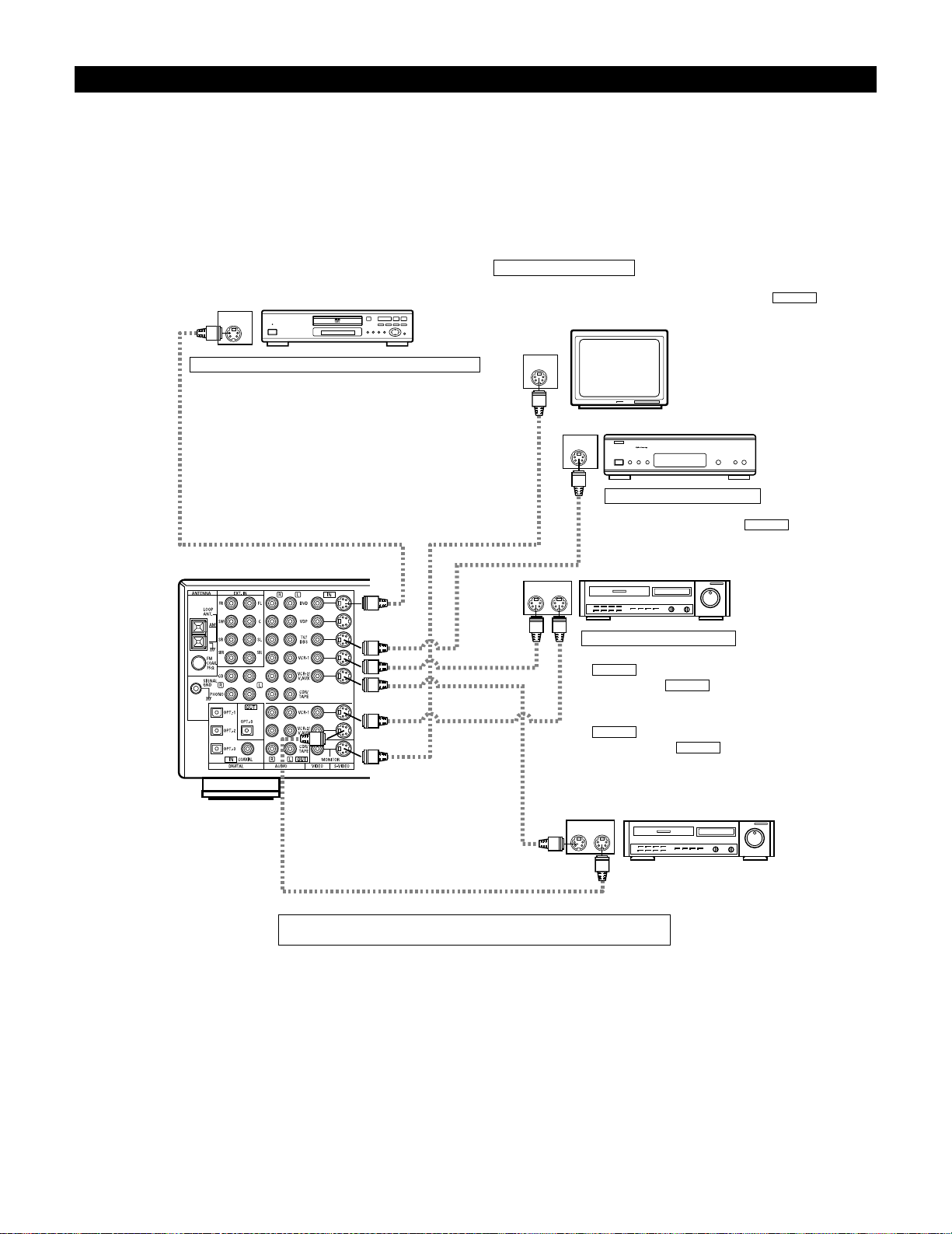
Connecting a video component equipped with S-Video jacks
• When making connections, also refer to the operating instructions of the other components.
• A note on the S input jacks
The input selectors for the S inputs and pin jack inputs work in conjunction with each other.
• Precaution when using S-jacks
This unit’s S-jacks (input and output) and video pin jacks (input and output) have independent circuit structures, so that video signals input from
the S-jacks are only output from the S-jack outputs and video signals input from the pin jacks are only output from the pin jack outputs.
When connecting this unit with equipment that is equipped with S-jacks, keep the above point in mind and make connections according to the
equipment’s instruction manuals.
DVD player or video disc player (VDP)
Connecting a DVD player or a video disc player (VDP)
DVD
• Connect the DVD player’s S-Video output jack to the S-VIDEO
DVD IN jack using an S-Video connection cord.
• A VDP can be connected to the VDP jacks in the same way.
• It is also possible to connect a video disc player, DVD player,
video camcorder, game machine, etc., to the VCR-2/V.AUX
jacks.
Connecting a monitor TV
MONITOR OUT
• Connect the TV’s S video input (S-VIDEO INPUT) to the MONITOR
OUT jack using a S jack connection cord.
S-VIDEO
Monitor TV
Connecting a TV/DBS tuner
• Connect the TV’s or DBS tuner’s S video output jack (SVIDEO OUTPUT) to the TV/DBS IN jack
using an S jack connection cord.
S-VIDEO
TV or satellite broadcast tuner
Video deck 1
Connecting the video decks
• Connect the video deck’s S output jack (S-OUT) to the
VCR-1 IN jack and the video deck’s S input jack
(S-IN) to the VCR-1 OUT jack using S jack
connection cords.
• Connect the video deck’s S output jack (S-OUT) to the
VCR-2/V.AUX IN jack and the video deck’s S input
jack (S-IN) to the VCR-2/V.AUX OUT jack using S
jack connection cords.
S-VIDEO
S-VIDEO
S-VIDEO
S-VIDEO
Video deck 2
Connect the components’ audio inputs and outputs as described on page 7.
YCRCB
VIDEO OUT
Y
CR CB
COMPONENT
VIDEO IN
COMPONENT
B
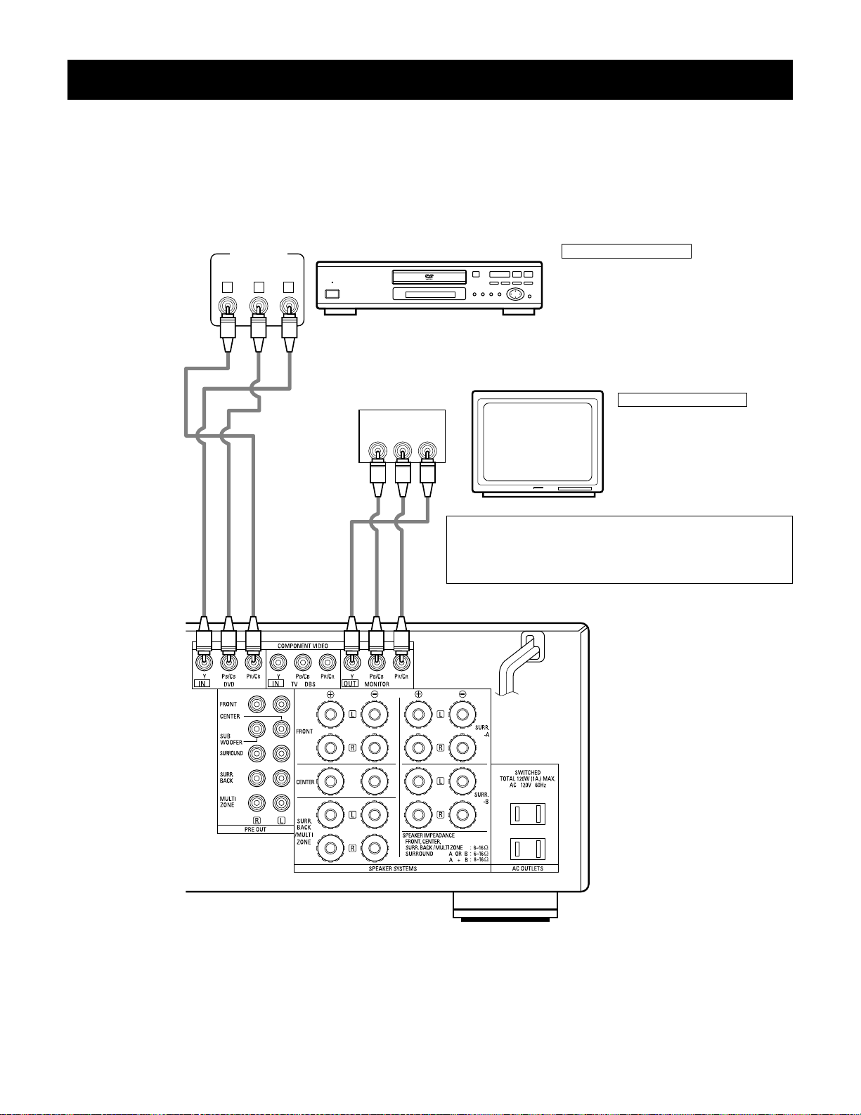
Connecting a Video Component Equipped with Color Difference (Component — Y, PR/CR, PB/CB) Video
Jacks (DVD Player)
• When making connections, also refer to the operating instructions of the other components.
• The signals input to the color difference (component) video jacks are not output from the VIDEO output jack (yellow) or the S-Video output jack.
In addition, the video signals input to the VIDEO input (yellow) and S-Video input jacks are not output to the color difference (component) video
jacks.
• The AVR-3802’s on-screen display signals are not output from the color difference (component) video output jacks (MONITOR OUT).
• Some video sources with component video outputs are labeled Y, CB, CR, or Y, Pb, Pr, or Y, R-Y, B-Y. These terms all refer to component video
color difference output.
DVD player
Connecting a DVD player
DVD IN jacks
• Connect the DVD player’s color difference
(component) video output jacks (COMPONENT
VIDEO OUTPUT) to the COMPONENT DVD IN jack
using 75 Ω/ohms coaxial video pin-plug cords.
• In the same way, another video source with
component video outputs such as a TV/DBS tuner,
etc., can be connected to the TV/DBS color
difference (component) video jacks.
Monitor TV
Connecting a monitor TV
MONITOR OUT jack
• Connect the TV’s color difference
(component) video input jacks
(COMPONENT VIDEO INPUT) to the
COMPONENT MONITOR OUT jack
using 75 Ω/ohms coaxial video pinplug cords.
• The color difference input jacks may be indicated differently on
some TVs, monitors or video components (“CR, CB and Y”, “R-Y,
B-Y and Y”, “Pr, Pb and Y”, etc.). For details, carefully read the
operating instructions included with the TV or other component.
14mm
9mm
14mm
19mm
5mm
5mm
5C-2V3C-2V
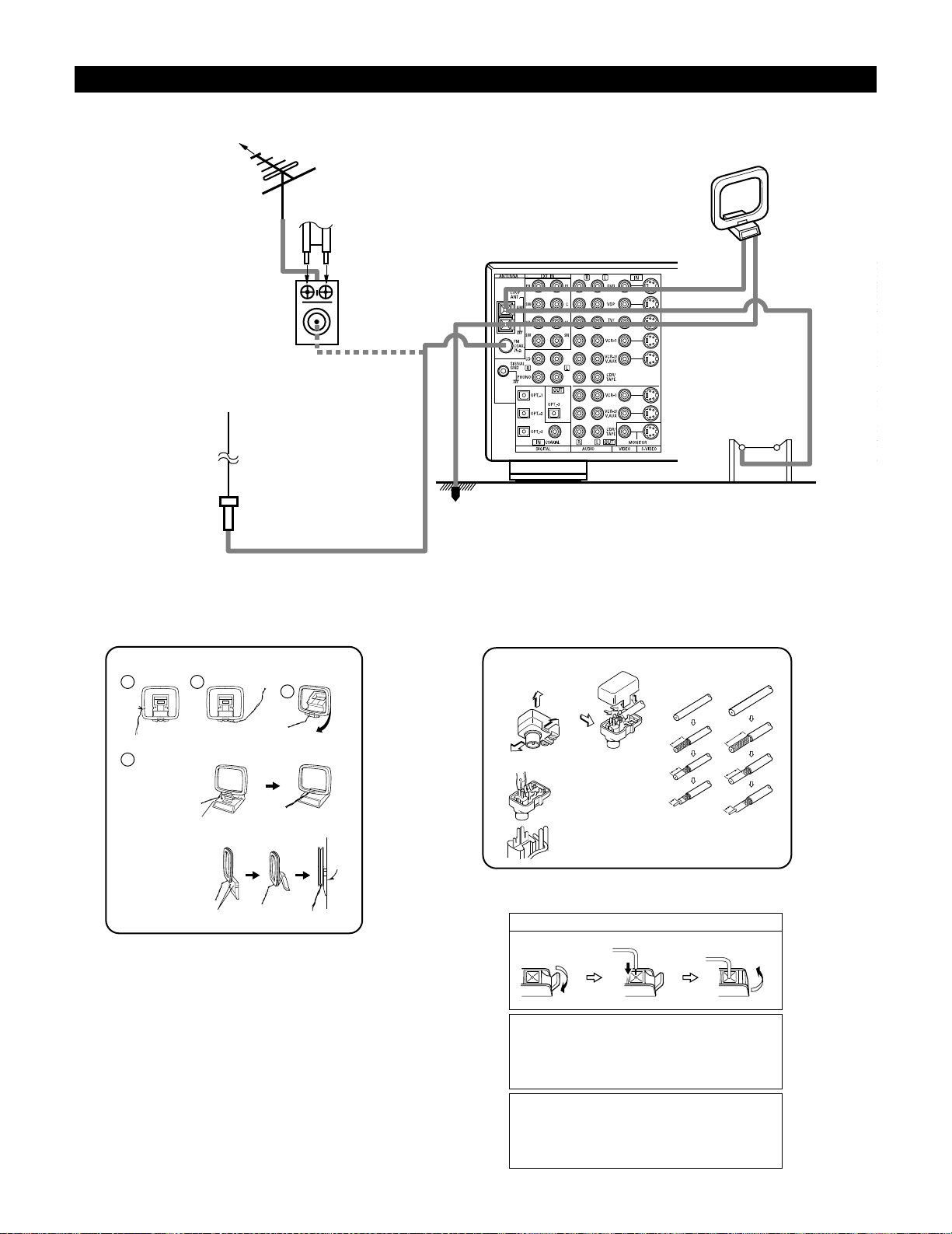
Connecting the antenna terminals
DIRECTION OF
BROADCASTING
STATION
75 Ω/ohms
COAXIAL
CABLE
FM ANTENNA
300 Ω/ohms
FEEDER
CABLE
FM INDOOR
ANTENNA
(Supplied)
300 Ω/ohms
AM LOOP
ANTENNA
(Supplied)
AM OUTDOOR
ANTENNA
GROUND
AM loop antenna assembly FM antenna adapter assembly
Connect to the AM
antenna terminals.
Remove the vinyl tie
and take out the
connection line.
Bend in the reverse
direction.
a. With the antenna
on top any stable
surface.
b. With the antenna
attached to a wall.
Mount
Installation hole
Mount on wall, etc.
75 Ω/ohms COAXIAL CABLE
Open the cover
ANTENNA ADAPTER
REMOVE
CLAMP
CLAMP
CLAMP
PULL
PULL
SHUT
Connection of AM antennas
1. Push the lever. 2. Insert the conductor. 3. Return the lever.
Note to CATV system installer:
This reminder is provided to call the CATV system installer’s
attention to Article 820-40 of the NEC which provides guidelines
for proper grounding and, in particular, specifies that the cable
ground shall be connected to the grounding system of the
building, as close to the point of cable entry as practical.
Notes:
• Do not connect two FM antennas simultaneously.
• Even if an external AM antenna is used, do not disconnect the
AM loop antenna.
• Make sure AM loop antenna lead terminals do not touch metal
parts of the panel.
FM ANTENNA
ADAPTER
(Supplied)
• An F-type FM antenna cable plug can be connected directly.
• If the FM antenna cable’s plug is not of the F-type, connect using the included antenna adapter.
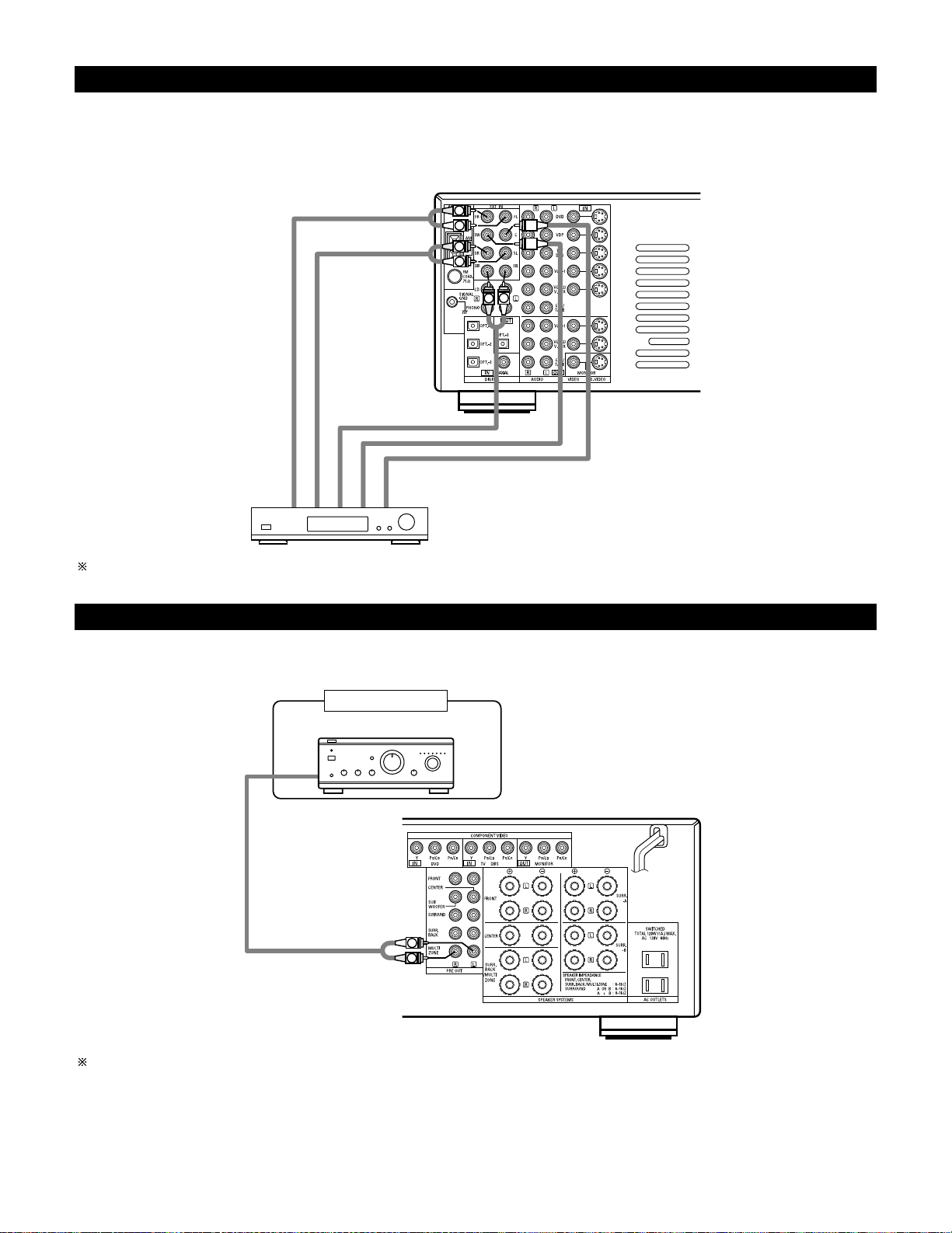
Connecting the external input (EXT. IN) jacks
• These jacks are for inputting multi-channel audio signals from an outboard decoder, or a component with a different type of multi-channel
decoder, such as a Super Audio DVD player, or a multi-channel SACD player, or other future multi-channel sound format decoder.
• When making connections, also refer to the operating instructions of the other components.
Decoder with 8- or 6-channel analog
output
Front
Surround
Surround back
Subwoofer
Center
For instructions on playback using the external input (EXT. IN) jacks, see page 44.
Connecting the MULTI ZONE jacks
• If another pre-main (integrated) amplifier or power amplifier is connected, the multi-source jacks can be used to play a different program source
in another room at the same time.
Another room
Integrated pre-main amplifier or power amplifier
For instructions on operations using the MULTI ZONE jacks, see page 46 ~ 48.
(L) (
R
)
(L) (
R
) (L) (
R
)
(L) (
R
)
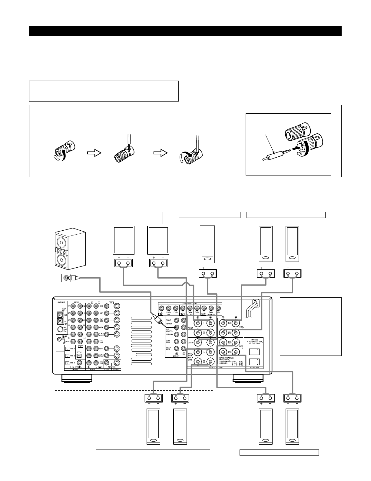
Speaker system connections
• Connect the speaker terminals with the speakers making sure that like
polarities are matched (
≈ with ≈ , √ with √ ). Mismatching of polarities will
result in weak central sound, unclear orientation of the various instruments,
and the sense of direction of the stereo being impaired.
• When making connections, take care that none of the individual conductors
of the speaker cord come in contact with adjacent terminals, with other
speaker cord conductors, or with the rear panel.
NOTE:
NEVER touch the speaker terminals when the power is on.
Doing so could result in electric shocks.
Speaker Impedance
• Speakers with an impedance of from 6 to 16 Ω/ohms can be connected for
use as front and center speakers.
• Speakers with an impedance of 6 to 16 Ω/ohms can be connected for use as
surround speakers.
• Be careful when using two pairs of surround speakers (A + B) at the same
time, since use of speakers with an impedance of less than 8 Ω/ohms will
lead to damage.
• The protector circuit may be activated if the set is played for long periods of
time at high volumes when speakers with an impedance lower than the
specified impedance are connected.
Connection the speaker terminals
1. Loosen by turning
counterclockwise
2. Insert the cord. 3. Tighten by turning
clockwise.
Connecting banana plugs
banana plug
Turn clockwise to tighten, then insert the
banana plug.
Connections
• When making connections, also refer to the operating instructions of the other components.
Connection jack for subwoofer
with built-in amplifier (super
woofer), etc.
FRONT SPEAKER
SYSTEMS
CENTER SPEAKER SYSTEM
SURROUND SPEAKER SYSTEMS (A)
• Precautions when
connecting speakers
If a speaker is placed near a
TV or video monitor, the
colors on the screen may
be disturbed by the
speaker’s magnetism. If
this should happen, move
the speaker away to a
position where it does not
have this effect.
SURROUND BACK/MULTI ZONE SPEAKER SYSTEMS
SURROUND SPEAKER SYSTEMS (B)
NOTES:
• To use Surround back with one
speaker, connect the speaker to
SURR. BACK L CH.
• The settings must be changed to use
this speaker for MULTI ZONE.
See page 18.
13
• This unit is equipped with a high-speed protection circuit. The purpose of this circuit is to protect the speakers under
circumstances such as when the output of the power amplifier is inadvertently short-circuited and a large current flows, when
the temperature surrounding the unit becomes unusually high, or when the unit is used at high output over a long period
which results in an extreme temperature rise.
When the protection circuit is activated, the speaker output is cut off and the power supply indicator LED flashes. Should
this occur, please follow these steps: be sure to switch off the power of this unit, check whether there are any faults with
the wiring of the speaker cables or input cables, and wait for the unit to cool down if it is very hot. Improve the ventilation
condition around the unit and switch the power back on.
If the protection circuit is activated again even though there are no problems with the wiring or the ventilation around the
unit, switch off the power and contact a DENON service center.
Protector circuit
• The protector circuit may be activated if the set is played for long periods of time at high volumes when speakers with an
impedance lower than the specified impedance (for example speakers with an impedance of lower than 4 Ω/ohms) are
connected. If the protector circuit is activated, the speaker output is cut off. Turn off the set’s power, wait for the set to cool
down, improve the ventilation around the set, then turn the power back on.
Note on speaker impedance
14
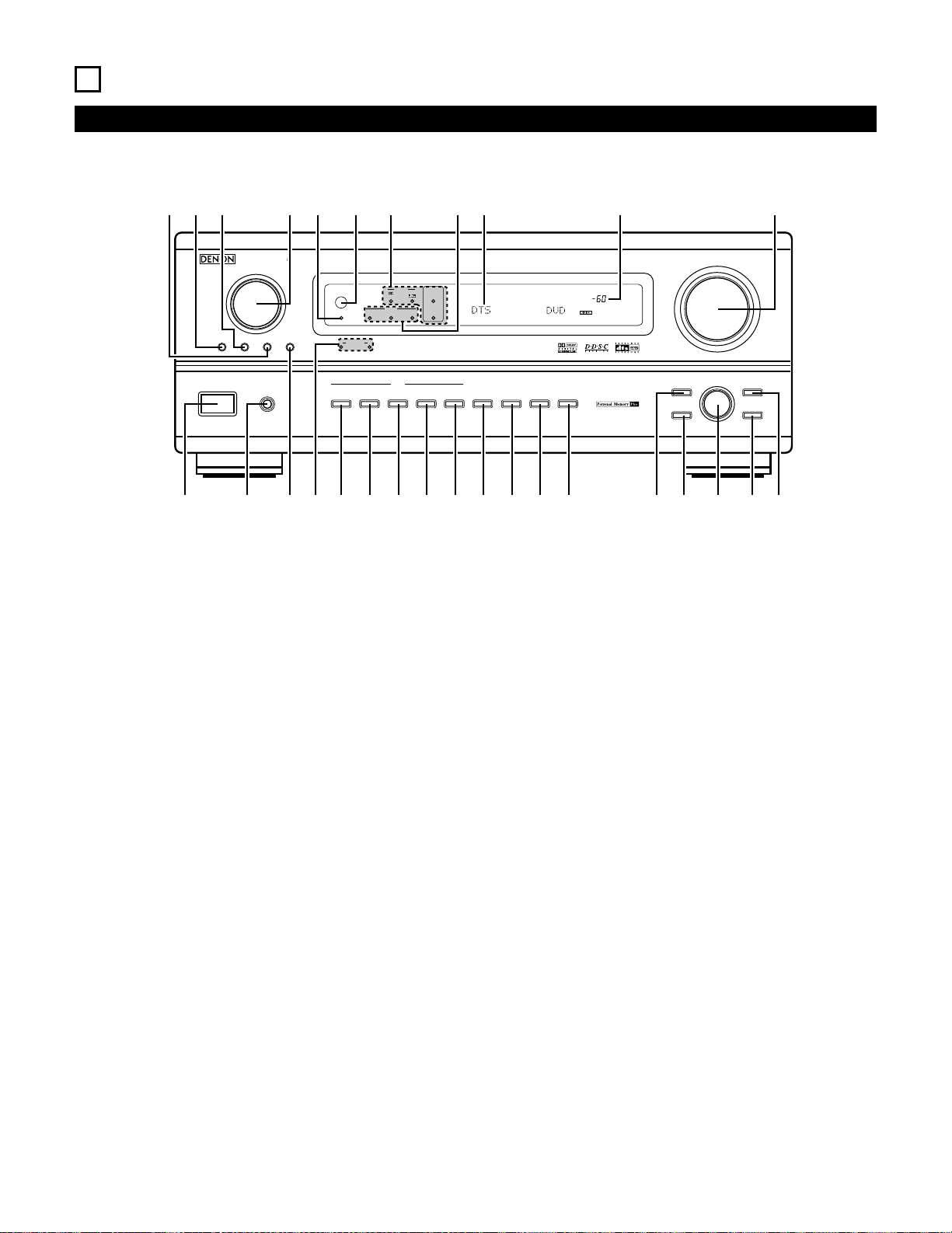
6
PART NAMES AND FUNCTIONS
Front Panel
• For details on the functions of these parts, refer to the pages given in parentheses ( ).
AVR-3802
PRECISION AUDIO COMPONENT / AV SURROUND RECEIVER
OUTPUT
SIGNAL
DETECT
SURROUND
BACK CH
TUNING
PRESET
REC /
MULTI
6.1 / 7.1
SURROUND
SOURCE
ON / STANDBY
REMOTE
SENSOR
FUNCTION
SURROUND
SPEAKER
A
B
AUTO
PCM
DTS
SIGNAL
DIGITAL
INPUT
VOLUME LEVEL
MASTER VOLUME
SURROUND
MODE
SURROUND
PARAMETER
TONE
CONTROL
SELECT CH VOL
DIMMER
STATUS TONE DEFEAT
VIDEO SELECT
INPUT
EXT. IN
ANALOG
AUTO PCM DTS
PHONES
ON / STANDBY
!8
!9@0@1@2@3@4@5@6@7@8@9
q w ter y u i o
!0 !1 !2 !3 !4 !5 !6 !7
q
Power ON/STANDBY switch…………………………………………….(41)
w
Headphones jack (PHONES) …………………………………………….(45)
e
6.1/7.1 SURROUND button………………………………………………(52)
r
Surround speaker system indicators
(SURROUND SPEAKER A/B)
t
AUTO button ………………………………………………………………….(42)
y
PCM button……………………………………………………………………(43)
u
DTS button …………………………………………………………………….(43)
i
ANALOG button ……………………………………………………………..(42)
o
EXT. IN button …………………………………………………………..(42, 44)
!0
VIDEO SELECT button …………………………………………………….(46)
!1
DIMMER button……………………………………………………………..(46)
!2
STATUS button ……………………………………………………………….(46)
!3
TONE DEFEAT button……………………………………………………..(45)
!4
SURROUND MODE button…………………………………………(43, 50)
!5
SURROUND PARAMETER button …………………………………….(51)
!6
SELECT knob………………………………………………………………….(43)
!7
TONE CONTROL button ………………………………………………….(45)
!8
CH VOL button……………………………………………………………….(49)
!9
MASTER VOLUME control ………………………………………………(43)
@0
Master volume indicator (VOLUME LEVEL) ……………………….(43)
@1
Display
@2
INPUT mode indicators ……………………………………………………(43)
@3
SIGNAL indicators …………………………………………………………..(43)
@4
Remote control sensor (REMOTE SENSOR) ………………………(29)
@5
Power indicator ………………………………………………………………(41)
@6
FUNCTION knob……………………………………………………………..(42)
@7
TUNING PRESET button ………………………………………………….(62)
@8
SOURCE selector button …………………………………………………(42)
@9
REC/MULTI button …………………………………………………….(46, 47)
1
2
3
456
789
+10
0
TV/
VCR
OFF
TV
CD
CDR/MD/TAPE RECEIVER
VCR DBS/CABLE
SKIP
SKIP
ENTER
MEMORY
VOLUME
CHANNEL
+
—
+
—
VDP DVD
POWER
REMOTE CONTROL UNIT
RC-883
ON /
SOURCE
TUNER
VDP
VCR-1 VCR-2/V.AUX
DVD
TV/DBS
CDR/TAPE
PHONO
CD
SURROUND
INPUT
OUTPUT
TEST
TONE
SPEAKER
6.1 / 7.1
SURROUND
5CH / 7CH
ANALOG
EXT.INMODE
CALL 2
BACKLIGHT
CALL 1
STEREO
STEREO
DOLBY/DTS
SURROUND
DSP
SIMU.
DISPLAY
SYSTEM CALL
DIRECT
RETURN
SETUP
MENU
SHIFT
SURR.
PARA.
OSD
A/B
MUTING
BAND MODE
TUNING
TUNING
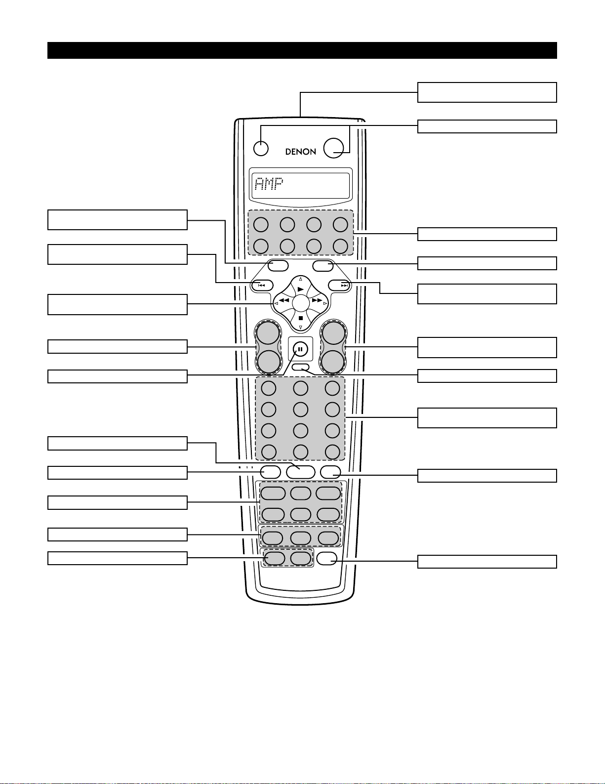
Remote control unit
• For details on the functions of these parts, refer to the pages given in parentheses ( ).
Master volume control
buttons ……………………………………………(43)
Mode selector buttons………………………(32)
Power button……………………………………(41)
MENU/OSD button……………………………(46)
RETURN/MEMORY/system
buttons ……………………………………………(61)
MUTING button………………………………..(45)
Input source selector
buttons ……………………………………………(42)
OUTPUT button………………………………..(45)
BACKLIGHT button
SYSTEM CALL buttons ……………………..(35)
Input mode selector buttons………………(42)
Surround mode buttons …………………….(55)
TEST TONE button……………………………(49)
Speaker selector button …………………….(55)
System buttons………………………………..(61)
ENTER/system button……………………….(16)
Tuner system/
system button ………………………………….(16)
System setup/
system buttons ………………………………..(16)
DISPLAY/SURR. PARA
button ……………………………………………..(51)
Remote control signal
transmitter……………………………………….(29)
7
SETTING UP THE SYSTEM
• Once all connections with other AV components have been completed as described in “CONNECTIONS” (see pages 6 to 13), make the various
settings described below on the monitor screen using the AVR-3802’s on-screen display function.
These settings are required to set up the listening room’s AV system centered around the AVR-3802.
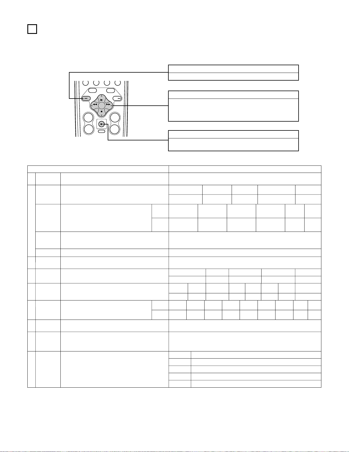
• Use the following buttons to set up the system:
SYSTEM SETUP button
Press this to display the system setup menu.
ENTER button
Press this to switch the display.
Also use this button to complete the setting.
CURSOR buttons
F and G: Use these to move the cursors (F and G) to the
left and right on the screen.
D and H: Use these to move the cursors (D and H) to the
up and down on the screen.
• System setup items and default values (set upon shipment from the factory)
System setup Default settings
q
w
t
y
u
i
o
Speaker
Configuration
Surround
Speaker
Setting
Subwoofer mode
SB CH Auto
Flag Detect
Channel
Level
Digital In
Assignment
On Screen
Display
Auto Tuner
Presets
Input the combination of speakers in your system and their
corresponding sizes (SMALL for regular speakers, LARGE for fullsize, full-range) to automatically set the composition of the signals
output from the speakers and the frequency response.
Use this function when using multiple surround speaker
combinations for more ideal surround sound. Once the
combinations of surround speakers to be used for the
different surround modes are preset, the surround
speakers are selected automatically according to the
surround mode.
This selects the subwoofer speaker for playing deep bass signals.
Set the method of playing the surround back channel for digital
signals.
This adjusts the volume of the signals output from the speakers and
subwoofer for the different channels in order to obtain optimum
effects.
This assigns the digital input jacks for the different input
sources.
This sets whether or not to display the on-screen display that
appears on the monitor screen when the controls on the remote
control unit or main unit are operated.
FM stations are received automatically and stored in the memory.
Surround
mode
Surround
speaker
Input
source
Digital
Inputs
Front Sp.
Large
Center Sp.
Surround Sp.
A / B
Sub Woofer
Small Small Yes
DOLBY/
DTS
SURROUND
5CH/7CH
STEREO
DSP
SIMULATION
EXT. IN
——
AAAA——
LFE
Front L & R Center Surround L & R Sub Woofer
12 ft (3.6 m) 12 ft (3.6 m) 10 ft (3.0 m) 12 ft (3.6 m)
Front L
Front R Center
Surround
R
Surround
Back R
Subwoofer
0 dB 0 dB 0 dB 0 dB 0 dB 0 dB
CD DVD TV/DBS
CDR/TAPE
VDP VCR-1 VCR-2 —
COAXIAL OPTICAL 1 OPTICAL 2 OPTICAL 3 OFF OFF OFF
—
On Screen Display = ON
A1 ~ A8
B1 ~B8
C1 ~C8
D1 ~D8
E1 ~E8
87.5/89.1/98.1/107.9/90.1/90.1/90.1/90.1 MHz
520/600/1000/1400/1500/1710 kHz, 90.1/90.1 MHz
90.1 MHz
90.1 MHz
90.1 MHz
Surround Back Sp.
Small / 2spkrs
DTS-ES / 6.1 Source Auto = OFF
e
Delay Time
This parameter is for optimizing the timing with which the audio
signals are produced from the speakers and subwoofer according to
the listening position.
SBL & SBR
10 ft (3.0 m)
r
This sets the output level for the multi output jacks. 0 dB
Surround
Back L
0 dB
Surround
L
0 dB
Multi
vol. Level
Power AMP
Assignment
Set this to switch the surround back channel’s power amplifier for
use for multi-zone.
Surround Back
—
—
Crossover
Frequency
Set the frequency (Hz) below which the bass sound of the various
speakers is to be output from the subwoofer.
80 Hz
TUNING
BAND MODE
TUNING
ENTER
SHIFT
MUTING
PH
MENU
OSD
RETURN
A/B
MEMORY
VOLUME
+
—
CD
SETUP
CHANNEL
+
SKIP
—
SKIP
TUNER
DISPLAY
SURR.
PARA.
17
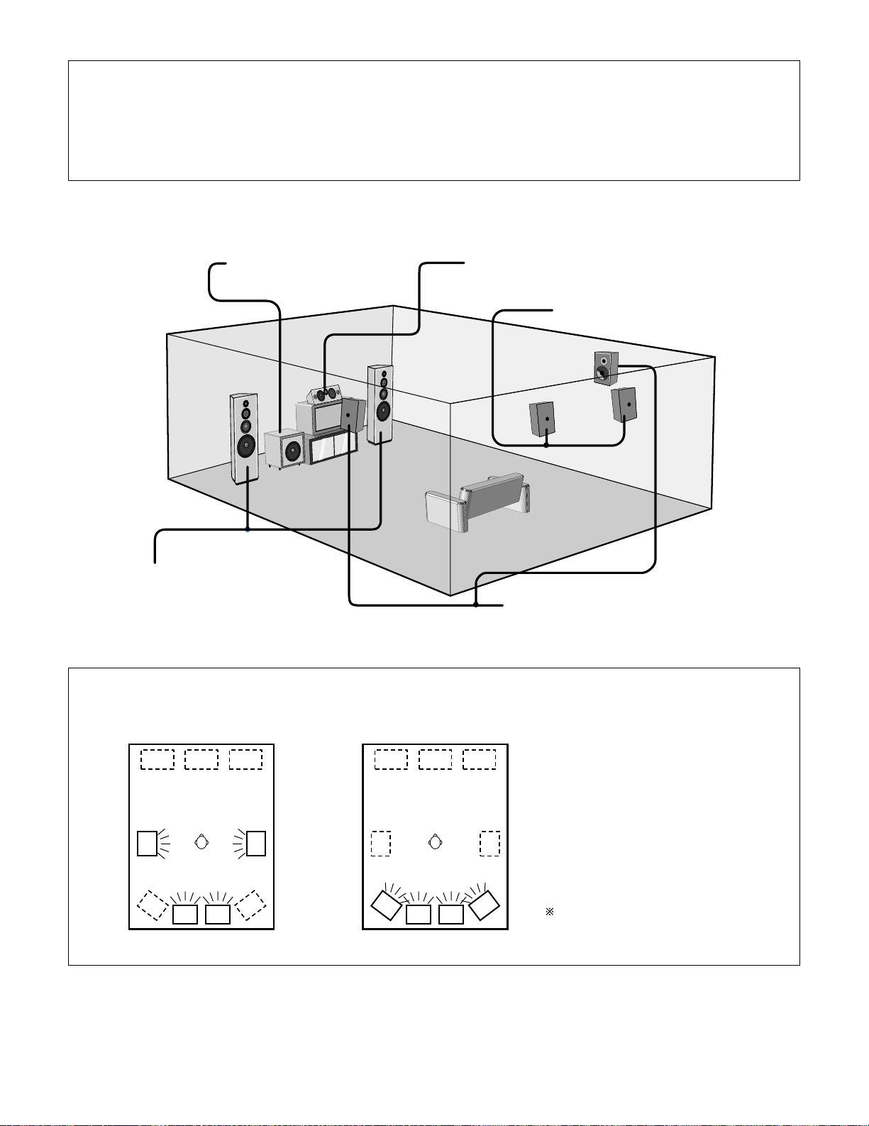
• Speaker system layout
Basic system layout
• The following is an example of the basic layout for a system consisting of eight speaker systems and a television monitor:
With the AVR-3802 it is also possible to use the surround speaker selector function to choose the best layout for a variety of sources and surround
modes.
Subwoofer Center speaker system
Surround speaker systems
Surround back speaker systems
Front speaker systems
Set these at the sides of the TV or screen with
their front surfaces as flush with the front of the
screen as possible.
• Surround speaker selector function
This function makes it possible to achieve the optimum sound fields for different sources by switching between two systems of surround
speakers (A and B).
Using A only Using B only
SB: SURROUND BACK SPEAKER
NOTES:
• The on-screen display signals are not output from the color difference (component) video signal (MONITOR OUT) jacks.
• The on-screen display signals are output with priority to the S-VIDEO MONITOR OUT jack during playback of a video component. For example, if the TV monitor
is connected to both the AVR-3802’s S-Video and video monitor output jacks and signals are input to the AVR-3802 from a video source (VDP, etc.) connected to
both the S-Video and video input jacks, the on-screen display signals are output with priority to the S-Video monitor output. If you wish to output the signals to
the video monitor output jack, do not connect a cord to the S-VIDEO MONITOR OUT jack. (For details, see page 28.)
• The AVR-3802’s on-screen display function is designed for use with high resolution monitor TVs, so it may be difficult to read small characters on TVs with small
screens or low resolutions.
• The setup menu is not displayed when “HEADPHONE ONLY” is selected.
18
Before setting up the system
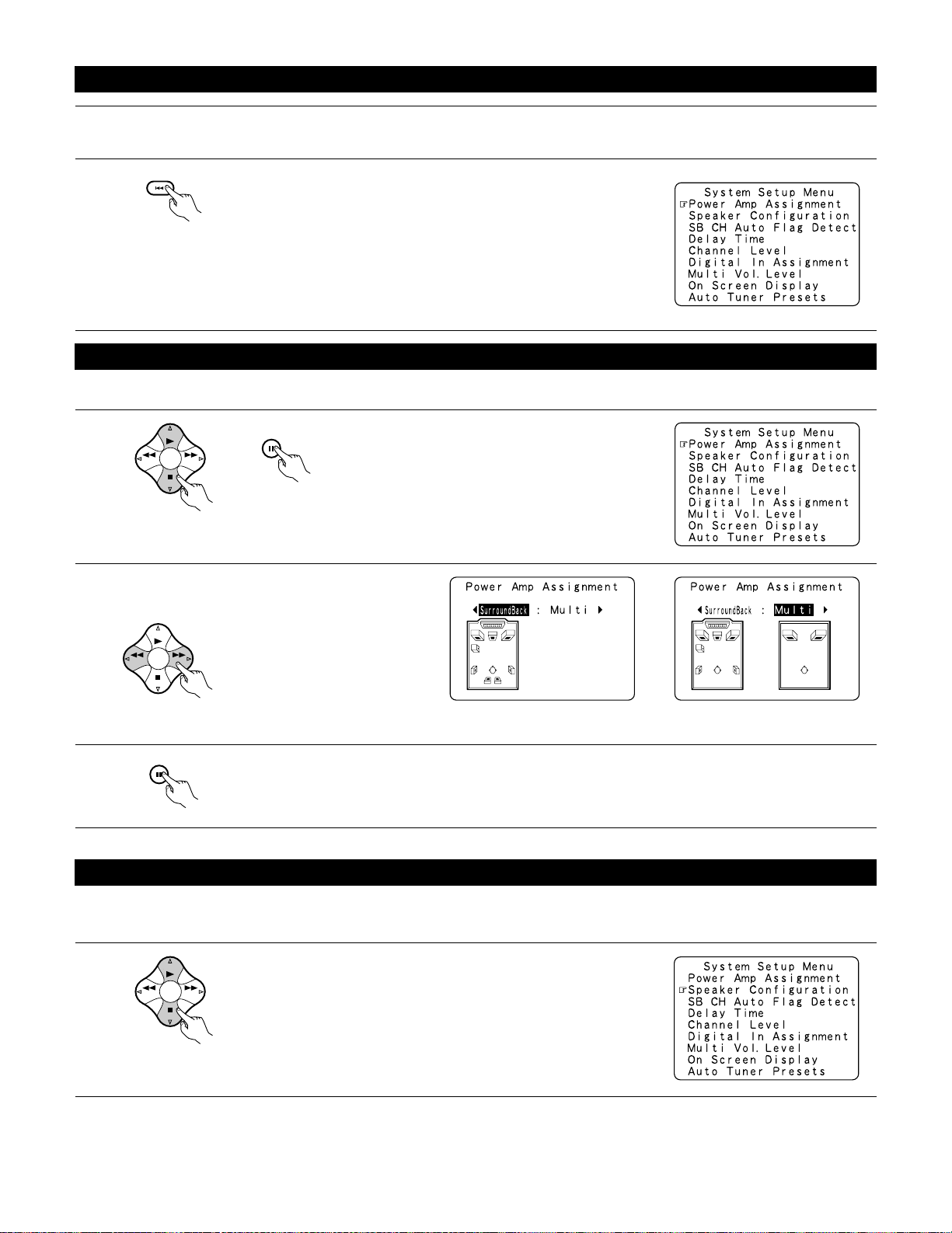
1
2
Check that all the connections are correct, then turn on the main unit’s power.
Display the System Setup Menu.
Make this setting to switch the power amplifier for the surround back channel to Multi.
1
At the System Setup Menu, select “Power Amp
Assignment” and press the ENTER button
3
Enter the setting.
The System Setup Menu reappears.
2
Select “Surround Back” to use as the surround back
channel, “Multi” to use as multi zone out.
When “Surround Back” is selected When “Multi” is selected
Setting the power amplifier assignment
Setting the type of speakers
• The composition of the signals output from the different channels and the frequency response are adjusted automatically according to the
combination of speakers actually being used.
1
At the System Setup Menu select “Speaker Configuration”.
Switch to the speaker configuration screen.
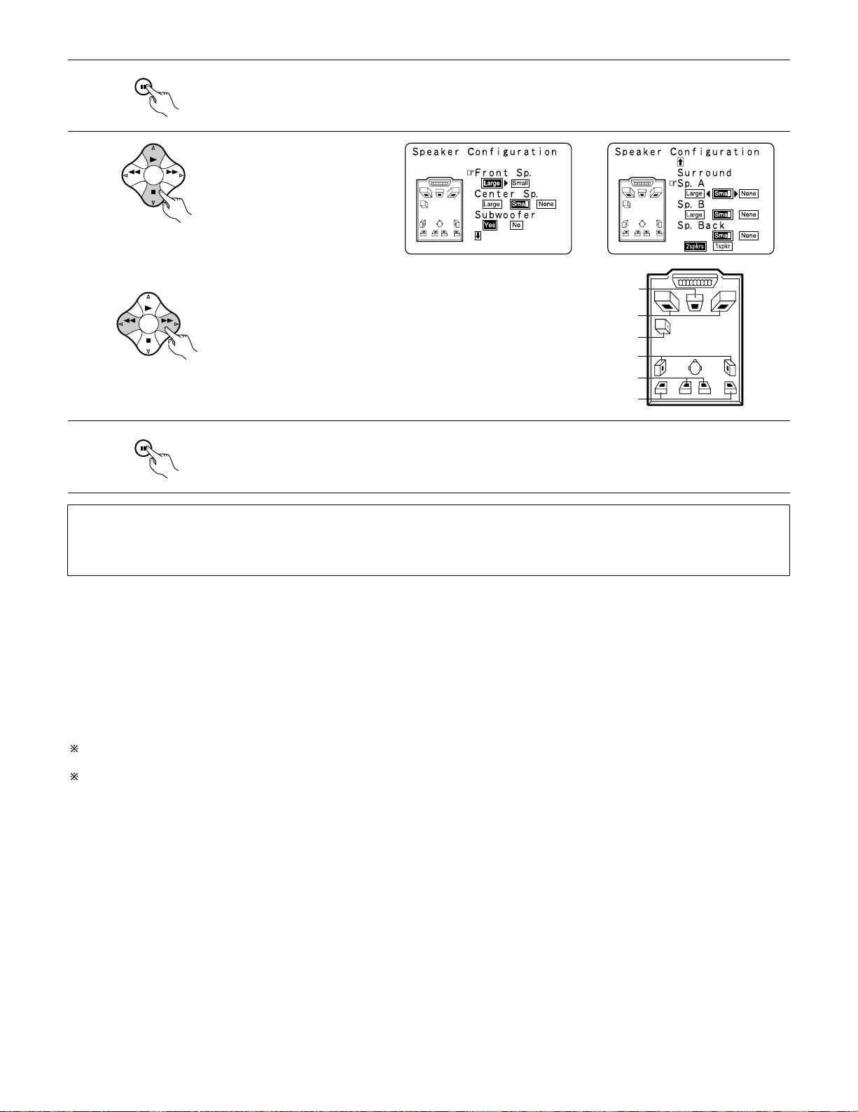
Set whether or not speakers are
connected and, if so, their size
parameters.
• To select the speaker
• To select the parameter
4
Press the ENTER button to finalize the setting.
NOTE:
• Select “Large” or “Small” not according to the actual size of the speaker but according to the speaker’s capacity for playing low frequency
(bass sound below frequency set for the Crossover Frequency mode and below) signals. If you do not know, try comparing the sound at both
settings (setting the volume to a level low enough so as not to damage the speakers) to determine the proper setting.
• Parameters
Large……………….Select this when using speakers that have sufficient performance for reproducing bass sound below the frequency set for the
Crossover Frequency mode.
Small……………….Select this when using speakers that do not have sufficient performance for reproducing bass sound below the frequency set
for the Crossover Frequency mode. When this is set, bass sound with a frequency below the frequency set for the Crossover
Frequency mode is sent to the subwoofer.
When this setting is selected, low frequencies of below the frequency set for the Crossover Frequency mode are assigned
to the subwoofer.
None………………Select this when no speakers are installed.
Yes/No…………….Select “Ye s” when a subwoofer is installed, “No” when a subwoofer is not installed.
2spkrs/1spkr …….Set the number of speakers to be used for the surround back channel.
If the subwoofer has sufficient low frequency playback capacity, good sound can be achieved even when “Small” is set for the front, center
and surround speakers.
For the majority of speaker system configurations, using the SMALL setting for all five main speakers and Subwooofer On with a connected
subwoofer will yield the best results.
Center Sp.
Front Sp.
Subwoofer
Surround Sp. A
Surround back Sp.
Surround Sp. B
Enter the setting.
When “Front” is set to “Large” and “Subwoofer” is set to “Ye s”, the set switches to the subwoofer mode.
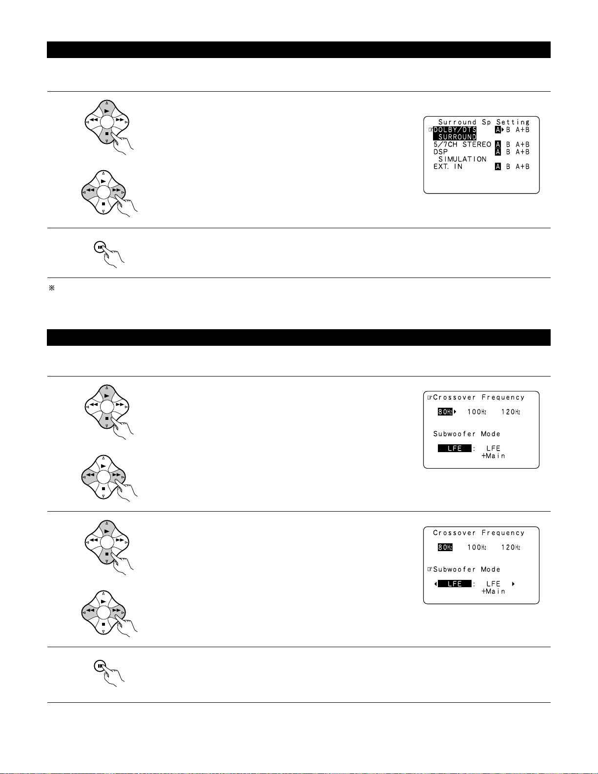
Speaker type setting when using both surround speakers A and B
If “Small” is set for either surround speakers A or B, the output is the same as when “Small” is set for both A and B.
Setting the Crossover Frequency and Subwoofer mode
1
3
Select the “Crossover Frequency” mode.
Enter the setting.
The System Setup Menu reappears.
This screen is not displayed when not using a subwoofer.
• Set the crossover frequency and subwoofer mode according to the speaker system being used.
Select the “Subwoofer Mode”.
Select the setting.
Selecting the surround speakers for the different surround modes
This screen is displayed when using both surround speakers A and B.
• At this screen preset the surround speakers to be used in the different surround modes.
1
When either “Large” or “Small” has been set for both speakers A and B
on the System Setup Menu (when using both A and B surround speakers),
the surround speaker setting screen appears.
Select the surround speakers to be used in the different surround modes.
• To select the surround mode
• To select the surround speaker
A: When using surround speakers A
B: When using surround speakers B
A+B: When using both surround speakers A and B
21
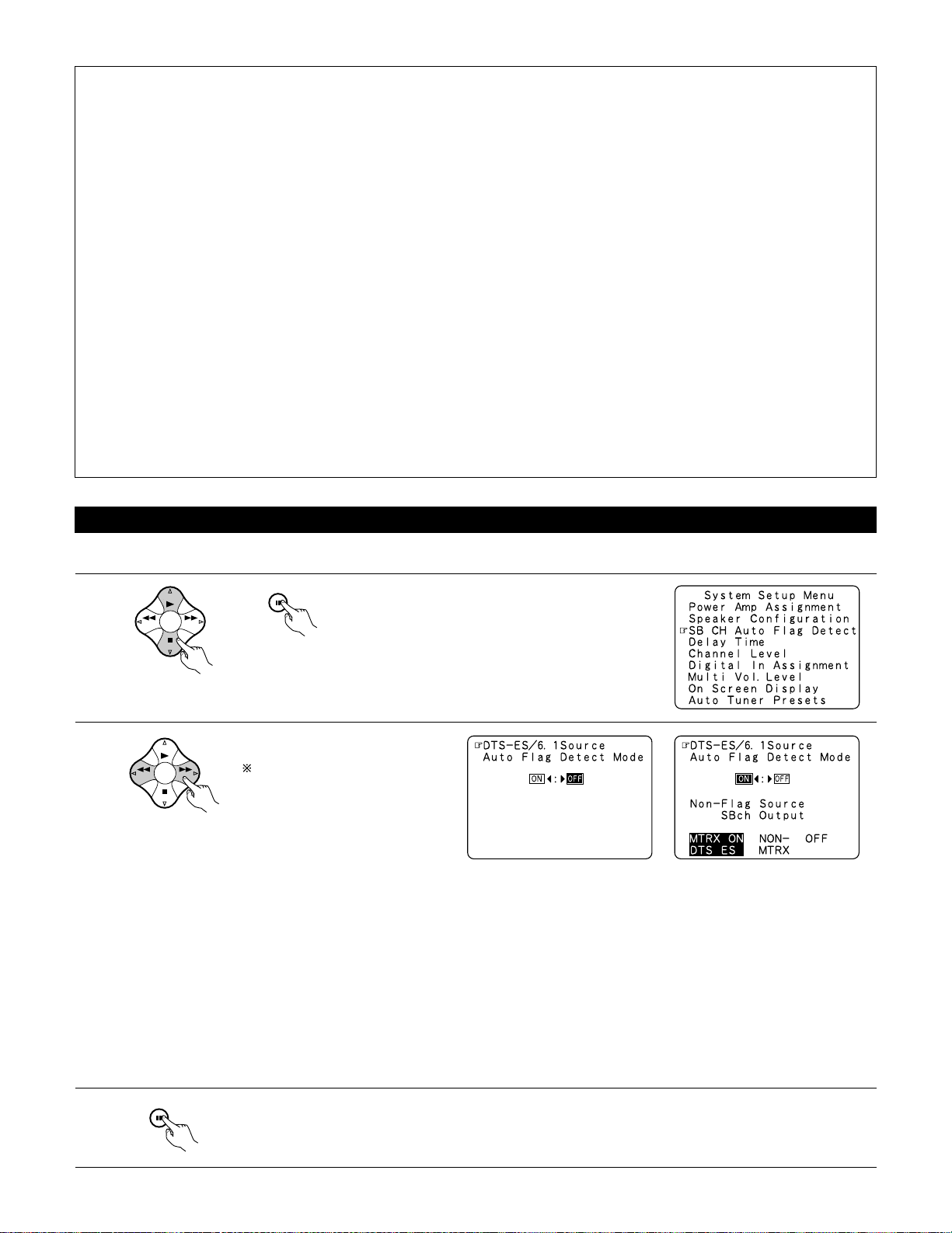
Setting the SB CH Auto Flag Detect
Set the operation for the digital signals when playing in the 6.1 SURROUND and DTS-ES surround modes.
1
At the System Setup Menu select “SB CH Auto Flag
Detect” and press the ENTER button.
2
Select the desired setting.
We recommend setting this to
“OFF”.
When set to “ON”, the
operation for software for which
no identification signals are
recorded is set.
3
Enter the setting.
The System Setup Menu reappears.
Setting
q Auto Flag Detect Mode (AFDM)
ON: This function only works for sources containing DTS-ES or 6.1-channel surround identification signals.
When this function is used, sources that have been recorded in 6.1-channel surround or DTS-ES are automatically played in the 6.1channel surround mode using the surround back speaker(s). (Refer to w for the method of playback of the surround back speaker in
this case.)
OFF: Set this mode if you wish to play normal 5.1-channel sources or sources not containing the identification signals described below in
the 6.1-channel mode.
w Non-Flag Source SBch Output
MTRX ON: Sources are played using the surround back speaker(s). The surround back channel is played with digital matrix processing.
NON-MTRX: Sources are played using the surround back speaker(s). The same signals as those of the surround channel are output from
the surround back speaker(s).
OFF: Sources are played without using the surround back speaker(s).
NOTES:
— Assignment of low frequency signal range —
• The only signals produced from the subwoofer channel are LFE signals (during playback of Dolby Digital or DTS signals) and the low
frequency signal range of channels set to “SMALL” in the setup menu. The low frequency signal range of channels set to “LARGE” are
produced from those channels.
— Crossover Frequency —
• When “Subwoofer” is set to “Ye s” at the “Speaker Configuration Setting”, set the frequency (Hz) below which the bass sound of the
various speakers is to be output from the subwoofer (the crossover frequency).
• For speakers set to “Small”, sound with a frequency below the crossover frequency is cut, and the cut bass sound is output from the
subwoofer instead.
NOTE:For ordinary speaker systems, we recommend setting the crossover frequency to 80 Hz. When using small speakers, however,
setting the crossover frequency to a high frequency may improve frequency response for frequencies near the crossover frequency.
— Subwoofer mode —
• The subwoofer mode setting is only valid when “LARGE” is set for the front speakers and “YES” is set for the subwoofer in the “Speaker
Configuration” settings (see page 18).
• When the “LFE+MAIN” playback mode is selected, the low frequency signal range of channels set to “LARGE” are produced
simultaneously from those channels and the subwoofer channel.
In this playback mode, the low frequency range expand more uniformly through the room, but depending on the size and shape of the room,
interference may result in a decrease of the actual volume of the low frequency range.
• Selection of the “LFE ” play mode will play the low frequency signal range of the channel selected with “LARGE” from that channel only.
Therefore, the low frequency signal range that are played from the subwoofer channel are only the low frequency signal range of LFE (only
during Dolby Digital or DTS signal playback) and the channel specified as “SMALL” in the setup menu.
• Select the play mode that provides bass reproduction with body.
• When the subwoofer is set to “Ye s”, bass sound is output from the subwoofer regardless of the subwoofer mode setting in surround modes
other than Dolby/DTS.
22
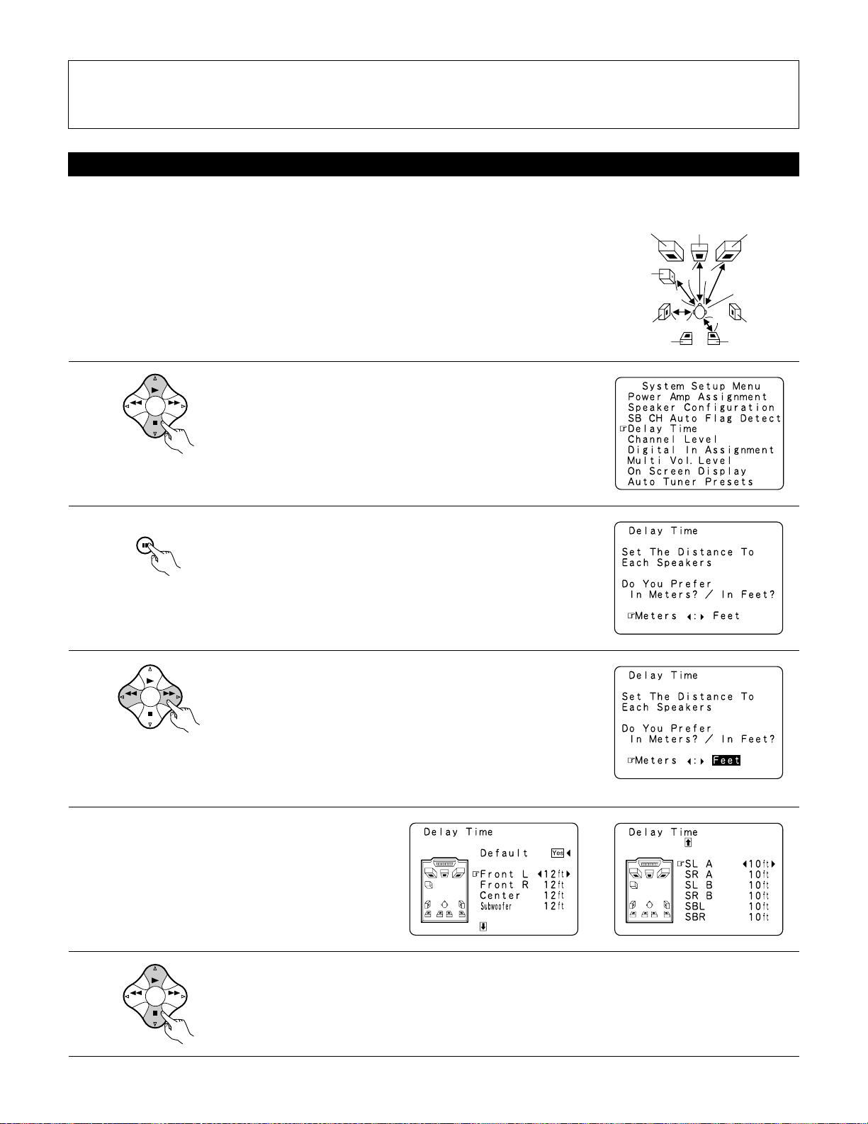
Setting the delay time
1
At the System Setup Menu select “Delay Time”.
• Input the distance between the listening position and the different speakers to set the delay time for the surround mode.
• The delay time can be set separately for surround speakers A and B.
Preparations:
Measure the distances between the listening position and the speakers (L1 to L5 on the diagram at
the right).
L1: Distance between center speaker and listening position
L2: Distance between front speakers and listening position
L3: Distance between surround speakers and listening position
L4: Distance between surround back speakers and listening position
L5: Distance between subwoofer and listening position
Center FRFL
Subwoofer
SL
Listening position
SR
SBRSBL
2
3
4
5
Switch to the Delay Time screen.
Select the desired unit, meters or feet.
Select (darken) the desired units, “Meters” or “Feet”.
Once “Meters” or “Feet” is selected in step 3, the
Delay Time screen appears automatically.
Select the speaker to be set.
Example: When “Feet” is selected
NOTES:
• The SB CH Auto Flag Detect setting screen is displayed when the surround back speaker(s) is/are set to “Large” or “Small” at the “Speaker
Configuration” screen.
• The surround back speaker(s) can also be turned on and off with the 6.1/7.1 SURROUND button on the main unit. (See page 52.)
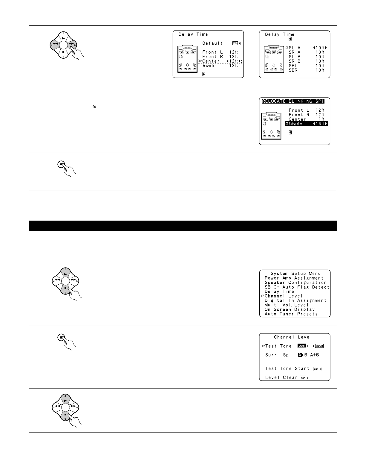
Set the distance between the
center speaker and listening
position.
The distance changes in units of 1
foot (0.1 meters) each time the
button is pressed. Select the value
closest to the measured distance.
If “Ye s ” is selected for “Default”, the settings are automatically reset
to the default values.
Please note that the difference of distance for every speaker should be 15
ft (4.5 m) or less. If you set an invalid distance, a CAUTION notice, such as
screen right will appear. In this case, please relocate the blinking speaker(s)
so that its distance is no larger than the value shown in highlighted line.
Example: When the distance is set to 12 feet
for the center speaker
7
Enter the setting.
The System Setup Menu reappears.
The AVR-3802 automatically sets the optimum surround delay time for the listening room.
NOTE:
• If the distance unit is changed after the delay time is set, the settings are reset to the factory default values (see page 16).
Setting the channel level
• Use this setting to adjust so that the playback level between the different channels is equal.
• From the listening position, listen to the test tones produced from the speakers to adjust the level.
• The level can also be adjusted directly from the remote control unit. (For details, see page 49.)
• When using both surround speakers A and B, their playback levels can be adjusted separately.
1
2
3
At the System Setup Menu select “Channel Level”.
Switch to the Channel Level screen.
Select “Test Tone Mode”.
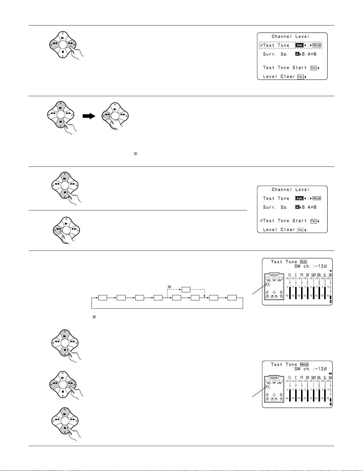
Select the mode.
Select “Auto” or “Manual”.
• Auto:
Adjust the level while listening to the test tones produced automatically
from the different speakers.
• Manual:
Select the speaker from which you want to produce the test tone to
adjust the level.
Select “Surr. Sp.”, then select the surround speaker(s) from which you want to produce the test tone (A, B or
A+B).
• Surr. Sp.: A
Adjusts the balance of the playback level between the channels when using surround speaker A.
• Surr. Sp.: B
Adjusts the balance of the playback level between the channels when using surround speaker B.
• Surr. Sp.: A+B
Adjusts the balance of the playback level between the channels when using surround speakers A and B at
the same time.
The “Surr. Sp.” can only be selected when both surround speakers A and B have been selected at the
System Setup Menu (when both A and B have been set to “Large” or “Small”).
Example: When the “Auto” mode is selected
6
7
8
Select “Test Tone Start”.
Select “Ye s ”.
a. If the “Auto” mode is selected:
Test tones are automatically emitted from the different speakers.
The test tones are emitted from the different speakers in the
following order, at 4-second intervals the first time and second time
around, 2-second intervals the third time around and on:
Use the CURSOR buttons to adjust all the speakers to the same
volume.
The volume can be adjusted between –12 dB and +12 dB in units of
1 dB.
b. When the “Manual” mode is selected
Use the CURSOR left and right to select the speaker for which you
want to output test tones, then use the CURSOR up and down to
adjust so that the volume of the test tones from the various speakers
is the same.
Example: When the volume is set to –12 dB
while the test tone is being
produced from the subwoofer
Example: When the volume is set to –12 dB
while the subwoofer is selected
Flashing
Flashing
FL C FR SR SBR SBL SL SW
SB
1spkr
2spkrs
When the surround back speaker setting is set to “1spkr” for
“Speaker Configuration”, this is set to “SB”.
After the above settings are completed, press the ENTER button.
The “Channel Level” screen reappears.
To cancel the settings, select “Level Clear” and “Ye s” on the “Channel Level” screen, then make the settings again.
The level of each channel should be adjusted to 75 dB (C-weighted, slow meter mode) on a sound level meter at the listening position.
If a sound level meter is not available adjust the channels by ear so the sound levels are the same. Because adjusting the subwoofer level test
tone by ear is difficult, use a well known music selection and adjust for natural balance.
NOTE: When adjusting the level of an active subwoofer system, you may also need to adjust the subwoofer’s own volume control.
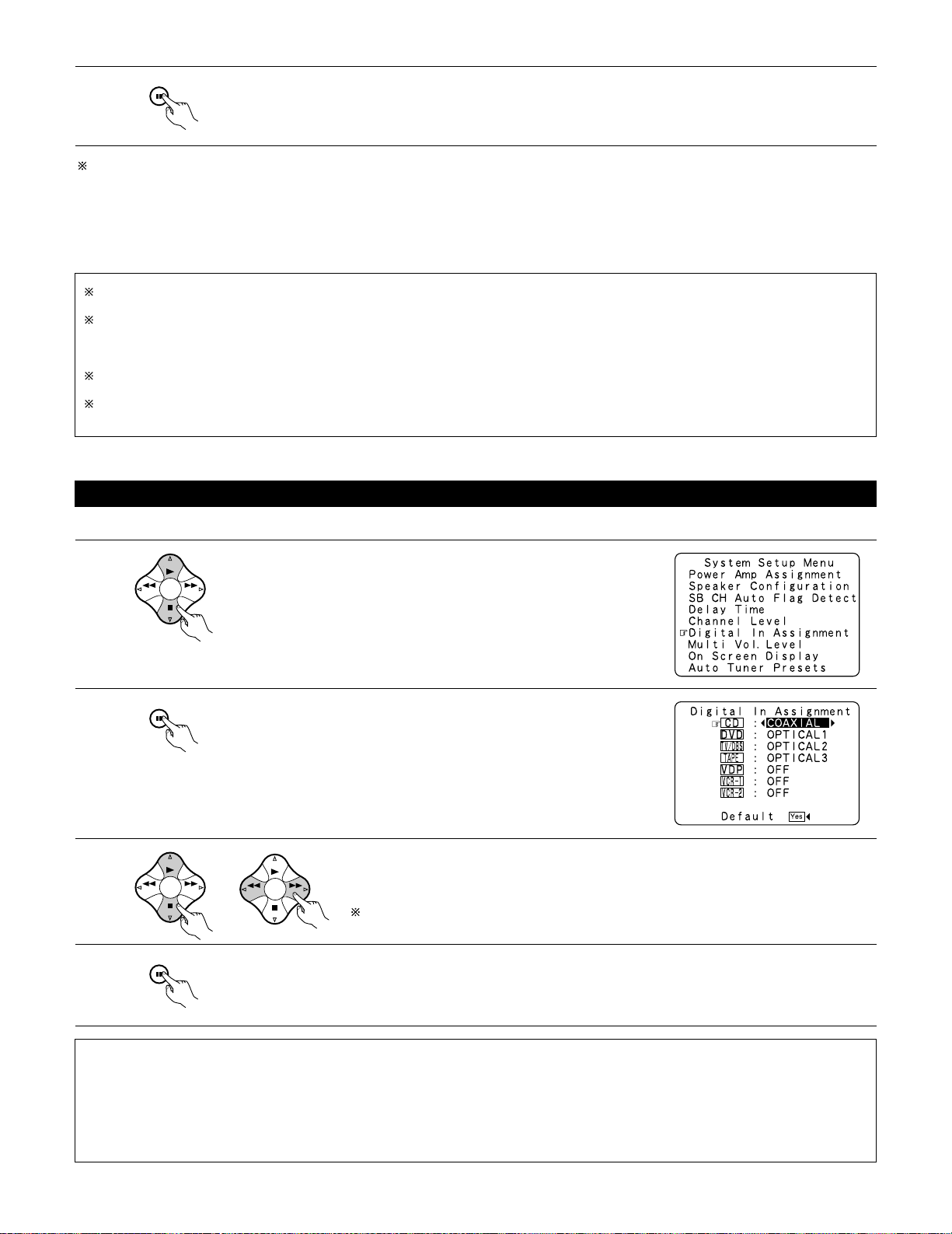
Setting the Digital In Assignment
• This setting assigns the digital input jacks of the AVR-3802 for the different input sources.
1
2
3
4
At the System Setup Menu select “Digital In Assignment”.
Switch to the Digital Inputs screen.
Select the digital input jack to be assigned to the input source.
• To select the input source
• To select the digital input jack
Select “OFF” for input sources for which no digital input jacks are used.
If “Ye s” is selected for “Default”, the settings are automatically reset to the default values.
Enter the setting.
The System Setup Menu reappears.
NOTES:
• The OPTICAL 3 jacks on the AVR-3802’s rear panel are equipped with an optical digital output jack for recording digital signals on a CD
recorder, MD recorder or other digital recorder. Use this for digital recording between a digital audio source (stereo — 2 channel) and a digital
audio recorder.
• Do not connect the output of the component connected to the OPTICAL 3 OUT jack on the AVR-3802’s rear panel to any jack other than the
OPTICAL 3 IN jack.
•“PHONO” and “TUNER” cannot be selected on the Digital In Assignment screen.
When you adjust the channel levels while in the SYSTEM SETUP CHANNEL LEVEL mode, the channel level adjustments made will affect
all surround modes. Consider this mode a Master Channel Level adjustment mode.
After you have completed the SYSTEM SETUP CHANNEL LEVEL adjustments, you can then activate the individual surround modes and
adjust channel levels that will be remembered for each of those modes. Then, whenever you activate a particular surround sound mode,
your preferred channel level adjustments for just that mode will be recalled. Check the instructions for adjusting channel levels within each
surround mode on page 49.
You can adjust the channel levels for each of the following surround modes: DIRECT, STEREO, 5/7 CH STEREO, DOLBY/DTS SURROUND,
WIDE SCREEN, ROCK ARENA, JAZZ CLUB, VIDEO GAME, MONO MOVIE, and MATRIX.
When using either surround speakers A or B, or when using surround speakers A and B at the same time, be sure to adjust the balance of
playback levels between each channel for the various selections of “A or B” and “A and B”.
26
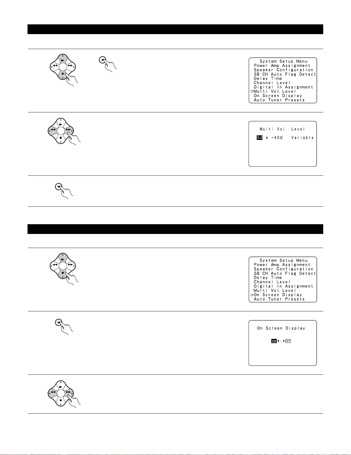
Setting the multi vol. level
Set the multi pre-out output level adjustment.
1
At the “System Setup Menu” screen, select “Multi
Vol. Level” and press the ENTER button.
2
3
Enter the setting.
The “System Setup Menu” reappears.
Select the desired settimg.
0 dB, -40 dB:
The output level is fixed at the set level and the volume can no longer be
adjusted.
Variable:
The level can be adjusted freely using the buttons on the remote control
unit.
Setting the on-screen display (OSD)
• Use this to turn the on-screen display (messages other than the menu screens) on or off.
1
At the System Setup Menu select “On Screen Display”.
2
3
Switch to the On Screen Display screen.
Select “ON” or “OFF”.
Enter the setting.
The System Setup Menu reappears.
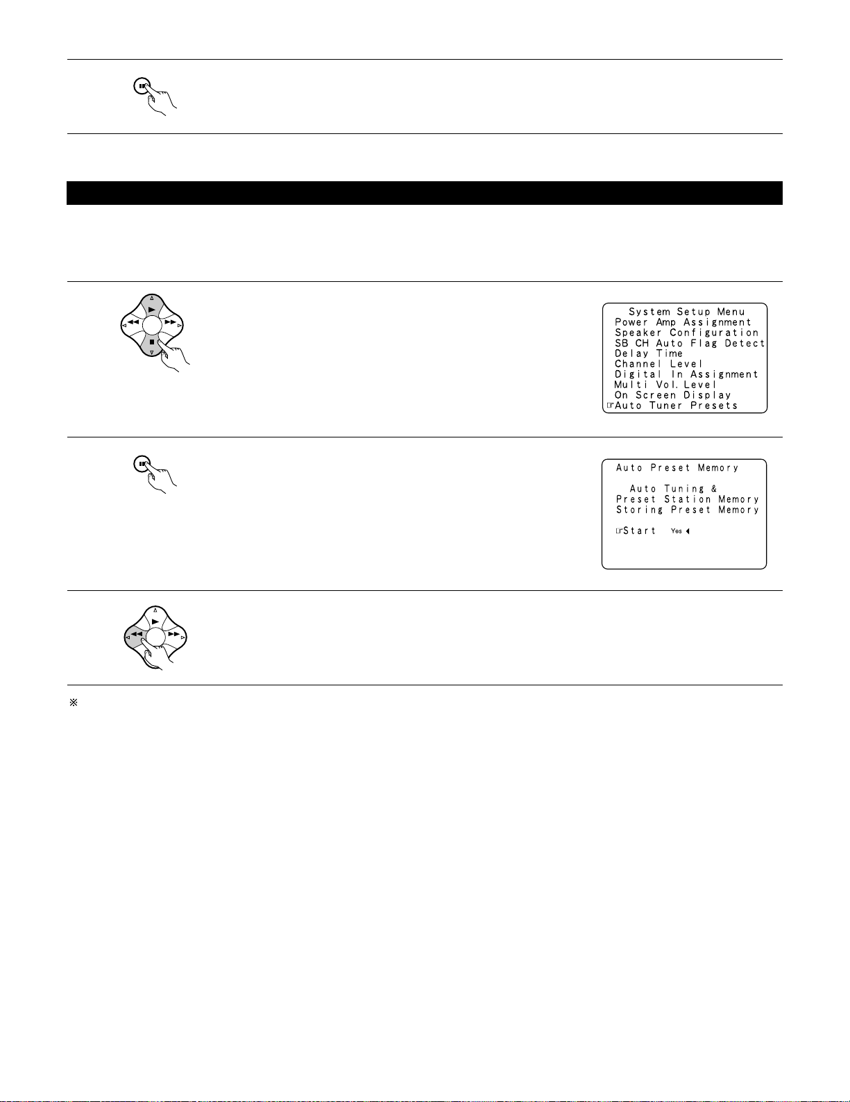
Auto tuner presets
Use this to automatically search for FM broadcasts and store up to 40 stations at preset channels A1 to 8, B1 to 8, C1 to 8, D1 to 8 and E1 to 8.
NOTE:
• If an FM station cannot be preset automatically due to poor reception, use the “Manual tuning” operation to tune in the station, then preset it
using the manual “Preset memory” operation.
1
Use the CURSOR buttons to specify “Auto Tuner Presets” from the
“System Setup Menu” screen.
2
3
Press the ENTER button.
The “Auto Preset Memory” screen appears.
Use the CURSOR button to select “Ye s”.
“Search” flashes on the screen and searching begins.
“Completed” appears once searching is completed.
The display automatically switches to screen.
This completes system setup. Once these settings are made, there is no need to change them unless different AV components are connected
or the speakers are repositioned.
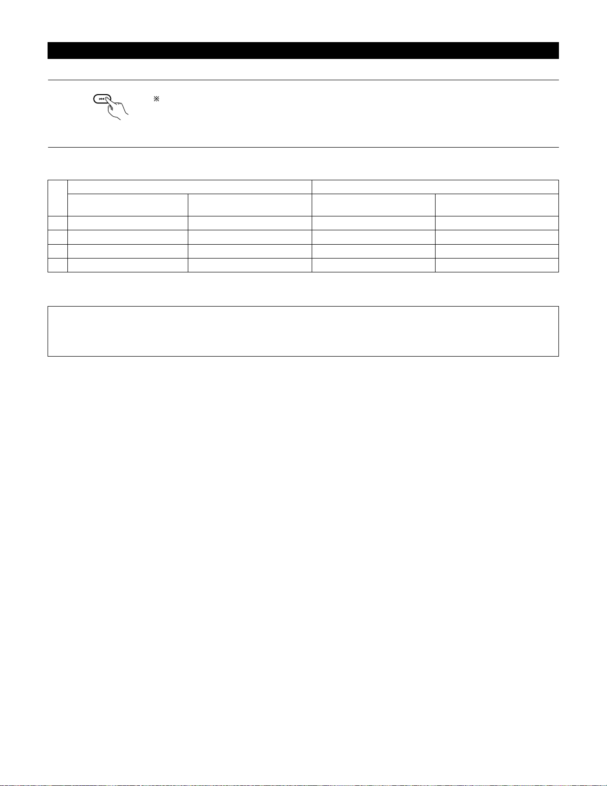
28
After completing system setup
This button can be pressed at any time during the system setup process to complete the process.
1
At the System Setup Menu, press the SYSTEM SETUP button.
The changed settings are entered and the on-screen display turns off.
• On-screen display signals
Signals input to the AVR-3802
VIDEO signal input jack (yellow)
E
C
E
C
1
2
3
4
S-video signal input jack
E
E
C
C
VIDEO MONITOR OUT video
signal output jack (yellow)
C
C
E
E
S-video MONITOR OUT video
signal output jack
C
E
C
C
On-screen display signal output
(C: Signal E: No signal) (C: On-screen signals output E: On-screen signals not output)
NOTES:
• The on-screen display signals are not output from the color difference (component) video signal MONITOR OUT jacks.
• For 4 above, the on-screen display signals are output to the VIDEO MONITOR OUT video signal output jack (yellow) if the monitor TV is not
connected to the S-video MONITOR OUT video signal output jack.
Loading…
Найди любой мануал:
Например: Sony VGN-FW460J/T
Вы можете бесплатно скачать Инструкция по эксплуатации для Denon AVR-3802.
Также вы сможете прочесть онлайн этот документ без скачивания.
Скачать Инструкция по эксплуатации для Denon AVR-3802
Тип файла
PDF
Размер
2.87 Mb
Кол-во страниц
74
Просмотров
6758
Читать онлайн Инструкция по эксплуатации для Denon AVR-3802 (Страница 1)

Другие Стереосистемы Denon AVR-3802
Топ Denon Стереосистемы
Ранее вы смотрели
Эта страница полезна для вас? Поделитесь ссылкой:
AVR-3802
PRECISION AUDIO COMPONENT / AV SURROUND RECEIVER
OUTPUT
SIGNAL
DETECT
SURROUND
BACK CH
TUNING
PRESET
REC /
MULTI
6.1 / 7.1
SURROUND
SOURCE
ON / STANDBY
REMOTE
SENSOR
FUNCTION
SURROUND
SPEAKER
A
B
AUTO
PCM
DTS
SIGNAL
DIGITAL
INPUT
VOLUME LEVEL
MASTER VOLUME
SURROUND
MODE
SURROUND
PARAMETER
TONE
CONTROL
SELECT
CH VOL
DIMMER
STATUS
TONE DEFEAT
VIDEO SELECT
INPUT
EXT. IN
ANALOG
AUTO
PCM
DTS
PHONES
ON / STANDBY
1
2
3
4
5
6
7
8
9
+10
0
TV/
VCR
OFF
TV
CD
CDR/MD/ TAPE RECEIVER
VCR
DBS/CABLE
SKIP
SKIP
ENTER
MEMORY
VOLUME
CHANNEL
+
—
+
—
VDP
DVD
POWER
REMOTE CONTROL UNIT
RC-883
ON /
SOURCE
TUNER
VDP
VCR-1
VCR-2 /V.AUX
DVD
TV/DBS
CDR/ TAPE
PHONO
CD
SURROUND
INPUT
OUTPUT
TEST
TONE
SPEAKER
6.1 / 7.1
SURROUND
5CH / 7CH
ANALOG
EXT.IN
MODE
CALL 2
BACKLIGHT
CALL 1
STEREO
STEREO
DOLBY/DTS
SURROUND
DSP
SIMU.
DISPLAY
SYSTEM CALL
DIRECT
RETURN
SETUP
MENU
SHIFT
SURR.
PARA.
OSD
A/B
MUTING
BAND
MODE
TUNING
TUNING
AV SURROUND RECEIVER
AVR-3802
OPERATING INSTRUCTIONS
2
We greatly appreciate your purchase of the AVR-3802.
2
To be sure you take maximum advantage of all the features the AVR-3802 has to offer, read these instructions
carefully and use the set properly. Be sure to keep this manual for future reference, should any questions or
problems arise.
“SERIAL NO.
PLEASE RECORD UNIT SERIAL NUMBER ATTACHED TO THE REAR OF THE
CABINET FOR FUTURE REFERENCE”
-
Page 1: Denon AVR-3802
AVR-3802 PRECISION AUDIO COMPONENT / AV SURROUND RECEIVER OUTPUT SIGNAL DETECT SURROUND BACK CH TUNING PRESET REC / MULTI 6.1 / 7.1 SURROUND SOURCE ON / STANDBY REMOTE SENSOR FUNCTION SURROUND SPEAKER A B AUTO PCM DTS SIGNAL DIGITAL INPUT VOLUME LEVEL MASTER VOLUME SURROUND MODE SURROUND PARAMETER TONE CONTROL SELECT CH VOL DIMMER STATUS TONE DEFEA[…]
-
Page 2: Denon AVR-3802
2 2 SAFETY PRECAUTIONS CAUTION RISK OF ELECTRIC SHOCK DO NOT OPEN CAUTION: TO REDUCE THE RISK OF ELECTRIC SHOCK, DO NOT REMOVE COVER (OR BACK). NO USER- SERVICEABLE P ARTS INSIDE. REFER SER VICING TO QUALIFIED SERVICE PERSONNEL. The lightning flash with arrowhead symbol, within an equilateral triangle, is intended to alert the user to the presence […]
-
Page 3: Denon AVR-3802
3 SAFETY INSTRUCTIONS 1. Read Instructions – All the safety and operating instructions should be read before the appliance is operated. 2. Retain Instructions – The safety and operating instructions should be retained for future reference. 3. Heed Warnings – All warnings on the appliance and in the operating instructions should be adhered to.[…]
-
Page 4: Denon AVR-3802
4 2 INTRODUCTION 2 ACCESSORIES Thank you for choosing the DENON Digital Surround A / V receiver . This remarkable component has been engineered to provide supe rb surround sound listening with home theater sources such as DVD, as well as providing outstanding high fidelity reproduction of your favorite music sources. As this product is provided wit[…]
-
Page 5: Denon AVR-3802
5 3 CAUTIONS ON HANDLING 4 FEA TURES • Switching the input function when input jacks are not connected A clicking noise may be produced if the input function is switched when nothing is connected to the input jacks. If this happens, either turn down the MASTER VOLUME control or connect components to the input jacks. • Muting of PRE OUT jacks, H[…]
-
Page 6: Denon AVR-3802
6 R L R L R INPUT OUTPUT LR L R OUTPUT L R L INPUT OPTICAL COAXIAL OUTPUT OPTICAL L R L R L R L R OUTPUT DIGITAL AUDIO DIGITAL AUDIO DIGITAL AUDIO DIGITAL AUDIO B B 5 CONNECTIONS • Do not plug in the AC cord until all connections have been completed. • Be sure to connect the left and right channels properly (left with left, right with right). ?[…]
-
Page 7: Denon AVR-3802
7 IN VIDEO R L R OUT IN AUDIO VIDEO OUT IN LRL R L R L R OUT IN AUDIO VIDEO OUT IN LRL R L R L R OUT VIDEO OUT L AUDIO L R R OUT VIDEO OUT L AUDIO L R R L R L R L R L RL B B Connecting video components • T o connect the video signal, connect using a 75 Ω /ohms video signal cable cord. Using an improper cable can result in a drop in video qualit[…]
-
Page 8: Denon AVR-3802
8 IN S-VIDEO OUT S-VIDEO OUT S-VIDEO OUT IN S-VIDEO OUT IN S-VIDEO B B Connecting a video component equipped with S-Video jacks • When making connections, also refer to the operating instructions of the other components. • A note on the S input jacks The input selectors for the S inputs and pin jack inputs work in conjunction with each other . […]
-
Page 9: Denon AVR-3802
9 Y C R C B VIDEO OUT Y C R C B COMPONENT VIDEO IN COMPONENT B Connecting a Video Component Equipped with Color Difference (Component — Y , P R /C R , P B /C B ) Video Jacks (DVD Player) • When making connections, also refer to the operating instructions of the other components. • The signals input to the color difference (component) video jack[…]
-
Page 10: Denon AVR-3802
10 14mm 9mm 14mm 19mm 5mm 5mm 5C-2V 3C-2V 1 4 2 3 Connecting the antenna terminals DIRECTION OF BROADCASTING ST A TION 75 Ω /ohms COAXIAL CABLE FM ANTENNA 300 Ω /ohms FEEDER CABLE FM INDOOR ANTENNA (Supplied) 300 Ω /ohms AM LOOP ANTENNA (Supplied) AM OUTDOOR ANTENNA GROUND AM loop antenna assembly FM antenna adapter assembly Connect to the AM[…]
-
Page 11: Denon AVR-3802
11 R L B L R L R RL Connecting the external input (EXT . IN) jacks • These jacks are for inputting multi-channel audio signals from an outboard decoder , or a component with a different type of multi-channel decoder , such as a Super Audio DVD player , or a multi-channel SACD player , or other future multi-channel sound format decoder . • When […]
-
Page 12: Denon AVR-3802
12 ( L ) ( R ) ( L ) ( R ) ( L ) ( R ) ( L ) ( R ) Speaker system connections • Connect the speaker terminals with the speakers making sure that like polarities are matched ( ≈ with ≈ , √ with √ ). Mismatching of polarities will result in weak central sound, unclear orientation of the various instruments, and the sense of direction of the[…]
-
Page 13: Denon AVR-3802
13 • This unit is equipped with a high-speed protection circuit. The purpose of this circuit is to protect the speakers under circumstances such as when the output of the power amplifier is inadvertently short-circuited and a large current flows, when the temperature surrounding the unit becomes unusually high, or when the unit is used at high ou[…]
-
Page 14: Denon AVR-3802
14 6 P ART NAMES AND FUNCTIONS Front Panel • For details on the functions of these parts, refer to the pages given in parentheses ( ). AVR-3802 PRECISION AUDIO COMPONENT / AV SURROUND RECEIVER OUTPUT SIGNAL DETECT SURROUND BACK CH TUNING PRESET REC / MULTI 6.1 / 7.1 SURROUND SOURCE ON / STANDBY REMOTE SENSOR FUNCTION SURROUND SPEAKER A B AUTO PCM[…]
-
Page 15: Denon AVR-3802
15 1 2 3 45 6 789 +1 0 0 TV/ VCR OFF TV CD CDR/MD / TAPE RECEIVER VCR DBS/ CABLE SKIP SKIP ENTER MEMORY VOLUME CHANNEL + — + — VDP DVD POWER REMOTE CONTROL UNIT RC-883 ON / SOURCE TUNER VDP VCR-1 VCR-2 / V.AUX DVD TV/DBS CDR/ TAPE PHONO CD SURROUND INPUT OUTPUT TEST TONE SPEAKER 6.1 / 7.1 SURROUND 5CH / 7CH ANALOG EXT.IN MODE CALL 2 BACKLIGHT CALL […]
-
Page 16: Denon AVR-3802
16 SKIP SKIP ENTER MEMORY VOLUME CHANNEL + — + — TUNER PH O N O CD DISPLAY RETURN SETUP MENU SHIFT SURR. PARA. OSD A/B MUTING BAND MODE TUNING TUNING 7 SETTING UP THE SYSTEM • Once all connections with other A V components have been completed as described in “ CONNECTIONS ” (see pages 6 to 13), make the various settings described below on the[…]
-
Page 17: Denon AVR-3802
17 • Speaker system layout Basic system layout • The following is an example of the basic layout for a system consisting of eight speaker systems and a television monitor: With the A VR-3802 it is also possible to use the surround speaker selector function to choose the best layout for a variety of sources and surround modes. Subwoofer Center s[…]
-
Page 18: Denon AVR-3802
18 Before setting up the system 1 2 Check that all the connections are correct, then turn on the main unit ’ s power . SETUP Display the System Setup Menu. Make this setting to switch the power amplifier for the surround back channel to Multi. 1 At the System Setup Menu, select “ Power Amp Assignment ” and press the ENTER button BAND MODE TUN[…]
-
Page 19: Denon AVR-3802
19 2 3 ENTER SHIFT BAND MODE TUNING TUNING BAND MODE TUNING TUNING Switch to the speaker configuration screen. Set whether or not speakers are connected and, if so, their size parameters. • T o select the speaker • T o select the parameter 4 ENTER SHIFT Press the ENTER button to finalize the setting. NOTE: • Select “ Large ” or “ Small […]
-
Page 20: Denon AVR-3802
20 2 ENTER SHIFT Enter the setting. When “ Front ” is set to “ Large ” and “ Subwoofer ” is set to “ Ye s ” , the set switches to the subwoofer mode. Speaker type setting when using both surround speakers A and B If “ Small ” is set for either surround speakers A or B, the output is the same as when “ Small ” is set for both[…]
-
Page 21: Denon AVR-3802
21 Setting the SB CH Auto Flag Detect Set the operation for the digital signals when playing in the 6.1 SURROUND and DTS-ES surround modes. 1 At the System Setup Menu select “ SB CH Auto Flag Detect ” and press the ENTER button. ENTER SHIFT BAND MODE TUNING TUNING 2 Select the desired setting. We recommend setting this to “ OFF ” . When set[…]
-
Page 22: Denon AVR-3802
22 Setting the delay time 1 BAND MODE TUNING TUNING At the System Setup Menu select “ Delay T ime ” . • Input the distance between the listening position and the different speakers to set the delay time for the surround mode. • The delay time can be set separately for surround speakers A and B. Preparations: Measure the distances between th[…]
-
Page 23: Denon AVR-3802
23 6 BAND MODE TUNING TUNING Set the distance between the center speaker and listening position. The distance changes in units of 1 foot (0.1 meters) each time the button is pressed. Select the value closest to the measured distance. If “ Ye s ” is selected for “ Default ” , the settings are automatically reset to the default values. Please[…]
-
Page 24: Denon AVR-3802
24 4 5 BAND MODE TUNING TUNING BAND MODE TUNING TUNING BAND MODE TUNING TUNING Select the mode. Select “ Auto ” or “ Manual ” . • Auto: Adjust the level while listening to the test tones produced automatically from the different speakers. • Manual: Select the speaker from which you want to produce the test tone to adjust the level. Sele[…]
-
Page 25: Denon AVR-3802
25 9 ENTER SHIFT After the above settings are completed, press the ENTER button. The “ Channel Level ” screen reappears. T o cancel the settings, select “ Level Clear ” and “ Ye s ” on the “ Channel Level ” screen, then make the settings again. The level of each channel should be adjusted to 75 dB (C-weighted, slow meter mode) on a […]
-
Page 26: Denon AVR-3802
26 Setting the multi vol. level Set the multi pre-out output level adjustment. 1 BAND MODE TUNING TUNING At the “ System Setup Menu ” screen, select “ Multi V ol. Level ” and press the ENTER button. 2 3 BAND MODE TUNING TUNING ENTER SHIFT Enter the setting. The “ System Setup Menu ” reappears. Select the desired settimg. 0 dB, -40 dB: T[…]
-
Page 27: Denon AVR-3802
27 4 ENTER SHIFT Enter the setting. The System Setup Menu reappears. BAND MODE TUNING TUNING Auto tuner presets Use this to automatically search for FM broadcasts and store up to 40 stations at preset channels A1 to 8, B1 to 8, C1 to 8, D1 to 8 and E1 to 8. NOTE: • If an FM station cannot be preset automatically due to poor reception, use the “[…]
-
Page 28: Denon AVR-3802
28 After completing system setup This button can be pressed at any time during the system setup process to complete the process. SETUP 1 At the System Setup Menu, press the SYSTEM SETUP button. The changed settings are entered and the on-screen display turns off. • On-screen display signals Signals input to the A VR-3802 VIDEO signal input jack ([…]
-
Page 29: Denon AVR-3802
29 8 REMOTE CONTROL UNIT • The included remote control unit (RC-883) can be used to operate not only the A VR-3802 but other remote control compatible DENO N components as well. In addition, the memory contains the control signals for other remote control units, so it can be used to operate non-Denon remote control compatible products. Inserting […]
-
Page 30: Denon AVR-3802
30 Operating DENON audio components 1 2 Use the mode selector buttons to select the component you want to operate. The mode switches between “ AMP ” , “ TUNER ” and “ MUL TI ” each time the RECEIVER button is pressed, between “ CDR ” , “ MD ” and “ T APE ” each time the CDR/MD/T APE button is pressed, between “ DBS ” and[…]
-
Page 31: Denon AVR-3802
31 Preset memory 1 2 3 45 6 789 +10 0 TV/ VCR OFF TV CD CDR/MD/ TAPE RECEIVER VCR DBS/CABLE SKIP SKIP ENTER MEMORY VOLUME CHANNEL + — + — VDP DVD POWER REMOTE CONTROL UNIT RC-883 ON / SOURCE TUNER VDP VCR-1 VCR-2/ V.AUX DVD TV/DBS CDR/TAPE PHONO CD SURROUND INPUT OUTPUT TEST TONE SPEAKER 6.1 / 7.1 SURROUND 5CH / 7CH ANALOG EXT.IN MODE CALL 2 BACKLI[…]
-
Page 32: Denon AVR-3802
32 Checking the preset memory settings 1 2 3 ON / SOURCE OFF ENTER SHIFT BAND MODE TUNING TUNING ENTER SHIFT Press the power ON/SOURCE button and the OFF button at the same time. •“ SET UP ” appears on the remote control unit ’ s display . Press the ENTER button. Use the D and H cursor buttons to display “ CODE NO ” on the remote contro[…]
-
Page 33: Denon AVR-3802
33 1 2 3 45 6 789 +10 0 TV/ VCR OFF TV CD CDR/MD/ TAPE RECEIVER VCR DBS/CABLE SKIP SKIP ENTER MEMORY VOLUME CHANNEL + — + — VDP DVD POWER REMOTE CONTROL UNIT RC-883 ON / SOURCE TUNER VDP VCR-1 VCR-2 /V.AUX DVD TV/DBS CDR/ TAPE PHONO CD SURROUND INPUT OUTPUT TEST TONE SPEAKER 6.1 / 7.1 SURROUND 5CH / 7CH ANALOG EXT.IN MODE CALL 2 BACKLIGHT CALL 1 ST[…]
-
Page 34: Denon AVR-3802
34 Learning function If your A V component is not a Denon product or if it cannot be operated using the preset memory , it can be controlled with the included remote control unit by storing its remote control signals in the remote control unit. 1 2 3 45 6 789 +10 0 TV/ VCR OFF TV CD CDR/MD/ TAPE RECEIVER VCR DBS/CABLE SKIP SKIP ENTER MEMORY VOLUME […]
-
Page 35: Denon AVR-3802
35 System call (1) System call buttons The buttons that can be used for the system call function are shown on the diagram at the right. System call signals can be stored at different buttons according to the mode. System call signals can be stored at a maximum of 6 buttons other than the CALL 1 and CALL 2 buttons. 29 successive operations can be se[…]
-
Page 36: Denon AVR-3802
36 5 6 Use the D and H cursor buttons to select the mode for the button at which the system call signals are to be registered, then press the ENTER button. “ SELECT KEY ” is displayed. Press the button at which the system call signals are to be registered, then press the ENTER button. •“ ENTER KEYS ” is displayed, then the mode display ap[…]
-
Page 37: Denon AVR-3802
37 4 Use the D and H cursor buttons to display “ RESET SYS ” on the remote control unit, then press the ENTER button. •“ SYS SEL ” appears on the remote control unit ’ s display . The remote control unit ’ s display switches as shown below each time the D and H cursor buttons are pressed. q T o reset CALL 1 or CALL 2, select “ SYS C[…]
-
Page 38: Denon AVR-3802
38 4 5 6 7 BAND MODE TUNING TUNING ENTER SHIFT BAND MODE TUNING TUNING ENTER SHIFT ENTER SHIFT Use the D and H cursor buttons to display “ RESET PRE ” on the remote control unit, then press the ENTER button. • After “ SEL PRE ” is displayed on the remote control unit ’ s display , the registered preset memory is displayed on the remote […]
-
Page 39: Denon AVR-3802
39 • This function is for resetting all the settings to the factory defaults. 1 2 3 45 6 789 +10 0 TV/ VCR OFF TV CD CDR/MD/ TAPE RECEIVER VCR DBS/CABLE SKIP SKIP ENTER MEMORY VOLUME CHANNEL + — + — VDP DVD POWER REMOTE CONTROL UNIT RC-883 ON / SOURCE TUNER VDP VCR-1 VCR-2/ V.AUX DVD TV/DBS CDR/TAPE PHONO CD SURROUND INPUT OUTPUT TEST TONE SPEAKE[…]
-
Page 40: Denon AVR-3802
40 Auto search function • The set is equipped with a function for searching for the registration number if you do not know the preset code (a 4-digit number) when setting the preset memory . 1 2 For TV , DBS or CABLE components, turn on the component ’ s power . For CD, MD, T APE, DVD, VCR and VDP component ’ s, turn on the component ’ s po[…]
-
Page 41: Denon AVR-3802
41 9 OPERA TION Before operating 1 Refer to “ CONNECTIONS ” (pages 6 to 13) and check that all connections are correct. 2 Select “ AMP ” using the RECEIVER button. (only when operating with the remote control unit) 3 T urn on the power . Press the POWER switch (button). RECEIVER ON / STANDBY (Main unit) (Remote control unit) Light B 3 ON / […]
-
Page 42: Denon AVR-3802
42 B 15 2 3 Playing the input source 1 Select the input source to be played. FUNCTION Example: CD 3 CD (Main unit) (Remote control unit) T o select the input source when REC MUL TI OUT or TUNING PRESET is selected, press the SOURCE button then operate the input function selector . 2 Select the input mode. • Selecting the analog mode Press the ANA[…]
-
Page 43: Denon AVR-3802
43 SIGNAL DIGITAL DIGITAL DIGITAL SIGNAL SIGNAL ANALOG DIGIT AL DIGIT AL DIGIT AL ANALOG AUTO INPUT PCM DTS AUTO INPUT PCM DTS AUTO INPUT PCM DTS AUTO INPUT PCM DTS PCM • Selecting the PCM mode Press the PCM button to switch to the PCM signal input. DTS • Selecting the DTS mode Press the DTS button to switch to the DTS signal input. 3 Example: […]
-
Page 44: Denon AVR-3802
44 Playback using the external input (EXT . IN) jacks 1 Set the external input (EXT . IN) mode. Press the EXT . IN to switch the external input. EXT.IN EXT.IN (Main unit) (Remote control unit) Once this is selected, the input signals connected to the FL (front left), FR (front right), C (center), SL (surround left), SR (surround right), SBL (surrou[…]
-
Page 45: Denon AVR-3802
45 After starting playback [1] Adjusting the sound quality (TONE) The tone control function will not work in the direct mode. 1 The tone switches as follows each time the TONE CONTROL button is pressed. TONE CONTROL (Main unit) 2 With the name of the volume to be adjusted selected, turn the SELECT knob to adjust the level. SELECT NOTE: T o prevent […]
-
Page 46: Denon AVR-3802
46 Multi-source recording/playback [1] Playing one source while recording another (REC OUT mode) 1 Press the REC/MUL TI button. REC / MULTI 2 With “ RECOUT SOURCE ” displayed, turn the FUNCTION knob to select the source you wish to record. • The “ REC ” indicator and the indicator of the selected source light. FUNCTION 3 Set the recording[…]
-
Page 47: Denon AVR-3802
47 [3] Remote control unit operations during multi-source playback (selecting the input source) This operation is possible when Multi mode is selected. This operation is not possible in the REC OUT mode. 1 Select “ MUL TI ” using the RECEIVER button. (Remote control unit) 2 Press the input source button. The multi source switches directly . [4][…]
-
Page 48: Denon AVR-3802
48 RC-617 AVR-3802 RC-616 B 2 MUL TI ZONE MUSIC ENTERT AINMENT SYSTEM (When using SPEAKER OUT) ANOTHER ROOM MAIN ROOM PROGRAMMABLE REMOTE CONTROL UNIT SYSTEM REMOTE CONTROL UNIT RC-883 ROOM-TO-ROOM REMOTE CONTROL SYSTEM (separately sold) control line MUL TI SOURCE SPEAKER cable SPEAKER cable * Refer to CONNECTIONS on pages 6 to 13. RC-617 AVR-3802 […]
-
Page 49: Denon AVR-3802
49 10 SURROUND Before playing with the surround function • Before playing with the surround function, be sure to use the test tones to adjust the playback level from the different speakers. This adjustment can be performed with the system setup (see page 23) or from the remote control unit, as described below . • Adjusting with the remote contr[…]
-
Page 50: Denon AVR-3802
50 Fader function • This function makes it possible to lower the volume of the front channels (FL, C and FR) or the rear channels (SL, SR, SBL and SBR) together . Use it for example to adjust the balance of the sound from the different positions when playing multi-channel music sources. 1 Select “ FADER ” . CH VOL ENTER SHIFT (Main unit) (Rem[…]
-
Page 51: Denon AVR-3802
51 NOTE: • There are four Dolby Surround Pro Logic modes (NORMAL, PHANTOM, WIDE and 3CH. LOGIC). The A VR-3802 sets the mode automatically according to the types of speakers set during the system setup process (page 18). 3 Set the surround parameter mode. SURROUND PARAMETER SURR. PARA. (Main unit) (Remote control unit) MODE CINEMA Display The on-[…]
-
Page 52: Denon AVR-3802
52 Dolby Digital mode (only with digital input) and DTS Surround mode (only with digital input) 1 Select the input source. Playback with a digital input q Select an input source set to digital (COAXIAL/OPTICAL) (see page 25). FUNCTION 5 VDP (Main unit) (Remote control unit) w Set the input mode to “ AUTO ” or “ DTS ” . AUTO DTS MODE (Main u[…]
-
Page 53: Denon AVR-3802
53 4 Display the surround parameter menu. SURR. PARA. (Remote control unit) SURROUND PARAMETER (Main unit) 5 Select the various parameters. SURROUND PARAMETER 6 BAND MODE TUNING TUNING (Remote control unit) (Main unit) SELECT BAND MODE TUNING TUNING (Remote control unit) (Main unit) Adjust the parameter settings. Surround parameters w CINEMA EQ. (C[…]
-
Page 54: Denon AVR-3802
54 11 DSP SURROUND SIMULA TION • The A VR-3802 is equipped with a high performance DSP (Digital Signal Processor) which uses digital signal processing to synthetically recreate the sound field. One of seven preset surround modes can be selected according to the program source and the parameters can be a djusted according to the conditions in the […]
-
Page 55: Denon AVR-3802
55 DSP surround simulation 1 Select the surround mode for the input channel. • T o operate the surround mode and surround parameters from the remote control unit. The surround mode switches in the following order each time the DSP SIMULA TION button is pressed: SURROUND 6.1 / 7.1 SURROUND 5CH / 7CH STEREO STEREO DOLBY/DTS SURROUND DSP SIMU. DIREC[…]
-
Page 56: Denon AVR-3802
56 • Operating the surround mode and surround parameters from the main unit ‘ s panel. 1 T urn the SELECT knob to select the surround mode. SELECT • When turned clockwise • When turned counterclockwise 2 Press the SURROUND P ARAMETER button. Press and hold in the surround parameter button to select the parameter you want to set. • The par[…]
-
Page 57: Denon AVR-3802
57 T one control setting • Use the tone control setting to adjust the bass and treble as desired. • T o operate the tone control from the remote control unit. 1 Display the surround parameter screen on the monitor . The screen for the selected surround mode appears. “ TONE ” cannot be selected in the Direct mode. SURR. PARA. 1 2 3 45 6 789 […]
-
Page 58: Denon AVR-3802
58 Surround parameters e MODE: (DTS NEO:6) • Cinema This mode is optimum for playing movies. Decoding is performed with emphasis on separation performance to achieve the same atmosphere with 2-channel sources as with 6.1-channel sources. This mode is effective for playing sources recorded in conventional surround formats as well, because the in-p[…]
-
Page 59: Denon AVR-3802
C C E E E E C C C C C C C C 59 2 Surround modes and parameters C : Signal E : No signal B : T urned on or off by speaker configuration setting C : Adjustable E : Not adjustable C : Able E : Unable Channel output FRONT L/R CENTER SURROUND L/R SUB- WOOFER SURROUND BACK L/R DIRECT STEREO EXTERNAL INPUT DOLBY PRO LOGIC II DTS NEO:6 DOLBY DIGIT AL (6.1 […]
-
Page 60: Denon AVR-3802
60 12 LISTENING TO THE RADIO If tuning does not stop at the desired station, use to the “ Manual tuning ” operation. 1 Set the input function to “ TUNER ” . FUNCTION 3 Watching the display , press the BAND button to select the desired band (AM or FM). BAND MODE TUNING TUNING 4 Press the MODE button to set the auto tuning mode. BAND MODE TUN[…]
-
Page 61: Denon AVR-3802
61 Checking the preset stations 1 Use the “ Auto tuning ” or “ Manual tuning ” operation to tune in the station to be preset in the memory . 2 Press the MEMORY button. MEMORY RETURN A/B 3 ENTER SHIFT Press the SHIFT button and select the desired memory block (A to E). 4 SKIP SKIP CHANNEL + — Press the CHANNEL + (UP) or – (DOWN) button to […]
-
Page 62: Denon AVR-3802
62 Recalling preset stations • T o call out preset stations from the remote control unit. 1 Watching the display , press the SHIFT button to select the preset memory block. ENTER SHIFT SKIP SKIP CHANNEL + — (Remote control unit) 2 Watching the display , press the CHANNEL + (UP) or – (DOWN) button to select the desired preset channel. (Remote co[…]
-
Page 63: Denon AVR-3802
63 15 TROUBLESHOOTING If a problem should arise,first check the following. 1. Are the connections correct ? 2. Have you operated the receiver according to the Operating Instructions ? 3. Are the speakers, turntable and other components operating proper ty ? If this unit is not operating properly , check the items listed in the table below . Should […]
-
Page 64: Denon AVR-3802
64 16 ADDITIONAL INFORMA TION Optimum surround sound for different sources There are currently various types of multi-channel signals (signals or formats with more than two channels). 2 T ypes of multi-channel signals Dolby Digital, Dolby Pro Logic, DTS, high definition 3-1 signals (Japan MUSE Hi-Vision audio), DVD-Audio, SACD (Super Audio CD), MPE[…]
-
Page 65: Denon AVR-3802
65 Surround back speakers A 6.1-channel system is a conventional 5.1-channel system to which the “ surround back ” (SB) channel has been added. This makes it easy to achieve sound positioned directly behind the listener , something that was previously difficult with sources designed for conven tional multi surround speakers. In addition, the ac[…]
-
Page 66: Denon AVR-3802
66 • Set the front speakers, center speaker and subwoofer in the same positions as in example (1). • It is best to place the surround speakers directly at the side or slightly to the front of the viewing position, and 60 to 90 cm above the ears. • Same as surround back speaker installation method (1). Using dipolar speakers for the surround b[…]
-
Page 67: Denon AVR-3802
67 • Set the front speakers slightly wider apart than the setup for watching movies only and point them toward the listening position in order assure clear positioning of the sound. • Set the center speaker in the same positions as in example (1). • Set surround speakers A for watching movies in the positions described in example (1) or (2), […]
-
Page 68: Denon AVR-3802
68 Surround The A VR-3802 is equipped with a digital signal processing circuit that lets you play program sources in the surround mode to ac hieve the same sense of presence as in a movie theater . Dolby Surround (1) Dolby Digital (Dolby Surround AC-3) Dolby Digital is the multi-channel digital signal format developed by Dolby Laboratories. Dolby D[…]
-
Page 69: Denon AVR-3802
69 DTS Digital Surround Digital Theater Surround (also called simply DTS) is a multi-channel digital signal format developed by Digital Theater Systems . DTS offers the same “ 5.1 ” playback channels as Dolby Digital (front left, front right and center , surround left and surround right) as well as the stereo 2-channel mode. The signals for the[…]
-
Page 70: Denon AVR-3802
70 DTS-ES Extended Surround TM DTS-ES Extended Surround is a new multi-channel digital signal format developed by Digital Theater Systems Inc. While offering high compatibility with the conventional DTS Digital Surround format, DTS-ES Extended Surround greatly improves the 360-degree surround impression and space expression thanks to further expand[…]
-
Page 71: Denon AVR-3802
71 System setup items and default values (set upon shipment from the factory) System setup Default settings q w t y u i o Speaker Configuration Surround Speaker Setting Subwoofer mode SB CH Auto Flag Detect Channel Level Digital In Assignment On Screen Display Auto T uner Presets Input the combination of speakers in your system and their correspond[…]
-
Page 72: Denon AVR-3802
72 C : Adjustable E : Not adjustable Surround modes and parameters Parameter (default values are shown in parentheses) TONE CONTROL CINEMA EQ. ROOM SIZE EFFECT LEVEL DELA Y TIME When playing Dolby Digital/DTS signals D. COMP LFE DIRECT STEREO EXTERNAL INPUT DOLBY PRO LOGIC II DTS NEO:6 DOLBY DIGIT AL (6.1 SURROUND) DTS SURROUND (DTS ES MTRX 6.1) 5/[…]
-
Page 73: Denon AVR-3802
73 17 SPECIFICA TIONS 2 Audio section • Power amplifier Rated output: Front: 110 W + 110 W (8 Ω /ohms, 20 Hz ~ 20 kHz with 0.05% T .H.D.) 150 W + 150 W (6 Ω /ohms, 1 kHz with 0.7% T .H.D.) Center: 110 W (8 Ω /ohms, 20 Hz ~ 20 kHz with 0.05% T .H.D.) 150 W (6 Ω /ohms, 1 kHz with 0.7% T .H.D.) Surround: 110 W + 110 W (8 Ω /ohms, 20 Hz ~ 2[…]
-
Page 74: Denon AVR-3802
14-14, AKASAKA 4-CHOME, MINA TO-KU, TOKYO 107-8011, JAP AN T elephone: (03) 3584-8111 Printed in Japan 511 3785 000[…]
Avr-3802, Av surround receiver, Output signal detect surround back ch
Table of contents
Document Outline
- ENGLISH
- 1. BEFORE USING
- 2. CAUTIONS ON INSTALLATION
- 3. CAUTIONS ON HANDLING
- 4. FEATURES
- 5. CONNECTIONS
- 6. When making connections, also refer to the operating instructions of the other components. PART NAMES AND FUNCTIONS 5
- 7. SETTING UP THE SYSTEM
- 8. REMOTE CONTROL UNIT
- 9. OPERATION
- 10. SURROUND
- 11. DSP SURROUND SIMULATION
- 12. LISTENING TO THE RADIO
- 13. LAST FUNCTION MEMORY
- 14. INITIALIZATION OF THE MICROPROCESSOR
- 15. TROUBLESHOOTING
- 16. ADDITIONAL INFORMATION
- 17. SPECIFICATIONS
- DEUTSCH
- 1. VOR INBETRIEBNAHME
- 2. VORSICHTSMASSNAHMEN ZUR INSTALLATION
- 3. VORSICHTSMASSNAHMEN ZUR HANDHABUNG
- 4. AUSSTATTUNGSMERKMALE
- 5. ANSCHLÜSSE
- 6. BEZEICHNUNG DER TEILE UND
- 7. SYSTEM-EINRICHTUNG
- 8. FERNBEDIENUNGSGERÄT
- 9. BETRIEB
- 10. SURROUND
- 11. DSP-SURROUND-SIMULATION
- 12. RADIOHÖREN
- 13. LETZTFUNKTIONSSPEICHER
- 14. INITIALISIERUNG DES MIKROPROZESSORS
- 15. FEHLERSUCHE
- 16. WISSENSWERTE ZUSATZINFORMATIONEN
- 17. TECHNISCHE DATEN
- FRANCAIS
- 1. AVANT L’UTILISATION
- 2. PRECAUTIONS D’INSTALLATION
- 3. PRECAUTIONS DE MANIPULATION
- 4. CARACTERISTIQUES
- 5. CONNEXIONS
- 6. NOMENCLATURE ET FONCTIONS
- 7. INSTALLATION DU SYSTEME
- 8. UNITE DE TELECOMMANDE
- 9. OPERATION
- 10. AMBIANCE
- 11. SIMULATION D’AMBIANCE DSP
- 12. ECOUTE DE LA RADIO
- 13. MEMOIRE DE DERNIERE FONCTION
- 14. INITIALISATION DU MICROPROCESSEUR
- 15. DEPISTAGE DES PANNES
- 16. INFORMATIONS SUPPLEMENTAIRES
- 17. SPECIFICATIONS
- ITALIANO
- 1. PRIMA DELL’USO
- 2. PRECAUZIONI SULL’INSTALLAZIONE
- 3. PRECAUZIONI SUL MANEGGIO
- 4. CARATTERISTICHE
- 5. COLLEGAMENTI
- 6. NOMENCLATURA E FUNZIONI
- 7. IMPOSTAZIONE DEL SISTEMA
- 8. TELECOMANDO
- 9. FUNZIONAMENTO
- 10. SURROUND
- 11. SIMULAZIONE SURROUND DSP
- 12. MEMORIA DELL’ULTIMA FUNZIONE
- 13. MEMORIA DELL’ULTIMA FUNZIONE
- 14. INIZIALIZZAZIONE DEL MICROPROCESSORE
- 15. LOCALIZZAZIONE DEI GUASTI
- 16. INFORMAZIONI ADDIZIONALI
- 17. SPECIFICHE
- ESPAÑOL
- 1. ANTES DE UTILIZAR EL APALATO
- 2. PRECAUCIONES EN LA INSTALACIÓN
- 3. PRECAUCIONES EN EL MANEJO
- 4. CARACTERÍSTICAS
- 5. CONEXIONES
- 6. NOMBRES Y FUNCIONES DE LAS PIEZAS
- 7. CONFIGURACIÓN DEL SISTEMA
- 8. MANDO A DISTANCIA
- 9. FUNCIONAMIENTO
- 10. SURROUND
- 11. SIMULACIÓN SURROUND DSP
- 12. RECEPCIÓN DE RADIO
- 13. MEMORIA DE LA ÚLTIMA FUNCIÓN
- 14. INICIARIZACIÓN DEL MICROPROCESADOR
- 15. RESOLUCIÓN DE PROBLEMAS
- 16. INFORMACIÓN ADICIONAL
- 17. ESPECIFICACIONES
- NEDERLANDS
- 1. VOOR GEBRUIK
- 2. VOORZORGSMAATREGELEN BIJ DE INSTALLATIE
- 3. VOORZORGSMAATREGELEN BIJ DE BEDIENING
- 4. KENMERKEN
- 5. AANSLUITINGEN
- 6. BENAMING VAN ONDERDELEN EN FUNCTIES
- 7. INSTELLING VAN HET SYSTEEM
- 8. AFSTANDSBEDIENING
- 9. BEDIENING
- 10. SURROUND
- 11. DSP SURROUND SIMULATIE
- 12. LUISTEREN NAAR DE RADIO
- 13. LAATSTE-FUNCTIEGEHEUGEN
- 14. INITIALISATIE VAN DE MICROPROCESSOR
- 15. OPLOSSING VAN PROBLEMEN
- 16. BIJKOMENDE INFORMATIE
- 17. TECHNISCHE GEGEVENS
- SVENSKA
- 1. INNAN DU BÖRJAR
- 2. VIKTIGA PUNKTER VID INSTALLATIONEN
- 3. VIKTIGT VID ANVÄNDNINGEN
- 4. EGENSKAPER
- 5. ANSLUTNING
- 6. DE OLIKA DELARNA OCH DERAS FUNKTIONER
- 7. SYSTEMINSTÄLLNINGAR
- 8. FJÄRRKONTROLL
- 9. ANVÄNDNING
- 10. SURROUND
- 11. SIMULERING MED DSP SURROUND
- 12. NÄR DU VILL LYSSNA PÅ RADIO
- 13. MINNE FÖR SENAST ANVÄNDA FUNKTION
- 14. NOLLSTÄLLA MIKROPROCESSORN
- 15. FELSÖKNING
- 16. ÖVRIG INFORMATION
- 17. TEKNISKA DATA