
14
SECTION 3 — EFFECTS AND PARAMETERS
ABOUT MODULES AND THE EFFECT CHARTS
The Studio Quad V2’s diverse selection of effect Modules allows you to achieve nearly endless combinations of
effects and routings. To accomplish that goal, we’ve supplied you with several different module types in an effects
configuration. The processing resources are divided one of four ways. Fig. 3-1 below uses pies to represent the pos-
sible resource division combination of the S-DISC.
Figure 3-1 The Resource Pies
Each section of the pies represents a different size Module in an effects configuration. In the diagram, there are three
different slice sizes: quarter, half, and whole. Likewise, the Module sizes available in the Studio Quad V2 are Quarter
(module type = 4th), Half (module type = HLF), and Whole (module type = FUL). A FUL module type offers
effects with more flexibility and power than the HLF modules, and so on, but all sizes of FX Modules feature very
high quality effects, so you don’t have to worry if you need to divide the Studio Quad V2 pie four ways. For a com-
plete list of these FX Types, see pg. 36. For a complete list of effect configurations, see pg. 37.
There are three basic types of FX Modules: Mono, Dual, and Stereo. Fig 3-2 illustrates what the signals do as they
enter the Module. Although all three Modules are shown with stereo inputs, they can still be used with a mono
source (such as input one of the Studio Quad V2). The mono source would just be routed to both sides of the
Module’s inputs. Notice how the Dual FX Module maintains stereo compatibility while the mono FX Module always
sums the signals together.
Figure 3-2 FX Module Types
DIGITAL AND ANALOG EFFECT LIST
A vast palette of Digital and Analog effects lies within the Studio Quad V2, all of which are Studio quality. The fol-
lowing are the Effects available: Reverbs, Choruses, Flangers, Phasers, Rotary Speaker Simulator, Tremolo, Auto-
Panner, Pitch Shifters, Detuners, Delays (Digital and Analog), Equalizers, Noise Gate, and Compressor.
ABOUT THE CHARTS
All the effects and Parameters found in the Studio Quad V2 are described in detail in the following group of charts.
Each chart is preceded by brief descriptions of the effects functions and description. Module names appear in the top
left corner of the chart with a vertical column of check boxes extending directly below. If the box is checked, the
Parameter appears in the Module.
Two Effect Types will be missing from these charts: Mute and Thru. These two Effect Types have no parameters and
simply function as their names imply. The Mute type keeps all signals from passing through an Effect module while
the Thru type allows only the dry signals to pass through a module.
Mono FX Module
Effect
Processing
Dual FX Module
Effect
Processing
Effect
Processing
Stereo FX Module
Section 3 — Effects and Parameters
Studio Quad V2 User’s Manual
Studio Quad V2
4 IN-4 OUT
Studio Effects Processor
A Harman International Company
1
2
FX Edit
Program
CompareCompare
4 IN 4 OUT MULTI-EFFECTS PROCESSOR
S-DISC
™
PROCESSING
1:Hall 2:Rm 3:Dly 4:Dtn
S-DISC
™
PROCESSING
IMPORTANT!
FOR YOUR PROTECTION, PLEASE READ THE FOLLOWING:
WATER AND MOISTURE: Appliance should not be used near water (e.g. near a bath-
tub, washbowl, kitchen sink, laundry tub, in a wet basement, or near a swimming pool, etc).
Care should be taken so that objects do not fall and liquids are not spilled into the enclosure
through openings.
POWER SOURCES: The appliance should be connected to a power supply only of the
type described in the operating instructions or as marked on the appliance.
GROUNDING OR POLARIZATION: Precautions should be taken so that the grounding
or polarization means of an appliance is not defeated.
POWER CORD PROTECTION: Power supply cords should be routed so that they are
not likely to be walked on or pinched by items placed upon or against them, paying particular
attention to cords at plugs, convenience receptacles, and the point where they exit from the
appliance.
SERVICING: The user should not attempt to service the appliance beyond that described
in the operating instructions. All other servicing should be referred to qualified service personnel.
FUSING: If your unit is equipped with a fuse receptacle, replace with only same type fuse.
Refer to replacement text on the unit for correct fuse type.
The symbols shown above are internationally accepted symbols that warn of potential
hazards with electrical products. The lightning flash with arrowpoint in an equilateral
triangle means that there are dangerous voltages present within the unit. The exclamation point in an equilateral triangle indicates that it is necessary for the user to refer
to the owner’s manual.
These symbols warn that there are no user serviceable parts inside the unit. Do not
open the unit. Do not attempt to service the unit yourself. Refer all servicing to qualified personnel. Opening the chassis for any reason will void the manufacturer’s warranty. Do not get the unit wet. If liquid is spilled on the unit, shut it off immediately
and take it to a dealer for service. Disconnect the unit during storms to prevent damage.
CAUTION
LITHIUM BATTERY WARNING
CAUTION!
This product contains a lithium battery. There is danger of explosion if battery is incorrectly replaced. Replace only with an Eveready CR 2032 or equivalent. Make sure the
battery is installed with the correct polarity. Discard used batteries according to manufacturer’s instructions.
ADVARSEL!
Lithiumbatteri — Eksplosjonsfare. Ved utskifting benyttes kun batteri som anbefalt av
apparatfabrikanten. Brukt batteri returneres apparatleverandøren.
ADVARSEL!
Lithiumbatteri — Eksplosionsfare ved fejlagtig håndtering. Udskiftning må kun ske med
batteri av samme fabrikat og type. Levér det brugte batteri tilbage til leverandøren.
VAROITUS!
Paristo voi räjähtää, jos se on virheellisesti asennettu. Vaihda paristo ainoastaan laitevalmistajan suosittelemaan tyyppin. Hävitä käytetty paristo valmistajan ohjeiden
mukaisesti.
VARNING!
Explosionsfara vid felaktigt batteribyte. Använd samma batterityp eller en ekvivalent typ
som rekommenderas av apparattillverkaren. Kassera använt batteri enligt fabrikantens
instruktion.
DECLARATION OF CONFORMITY
Manufacturer’s Name: Harman Music Group Incorporated
Manufacturer’s Address: 8760 S. Sandy Parkway
Sandy, Utah 84070, USA
declares that the product:
Product Name Studio Quad V2
Product Options: All
conform to the following Product Specifications:
Safety: EN 60065 (1993)
IEC 65 (1987) with Amendments 1, 2 & 3
EMC: EN 55013 (1990)
EN 55020 (1991)
Supplementary Information:
The product herewith complies with the requirements of the Low Voltage Directive 73/23/EEC and the EMC Directive 89/336/EEC as amended by
Directive 93/68/EEC.
Digitech Electronics
President of DigiTech
8760 S. Sandy Parkway
Sandy, Utah 84070, USA
Effective October 2, 1996
European Contact: Your Local DigiTech Sales and Service Office
or International Sales Office
3 Overlook Drive #4
Amherst, New Hampshire 03031, USA
Tel (603) 672-4244
Fax (603) 672-4246
RISK OF ELECTRIC SHOCK
DO NOT OPEN
ATTENTION: RISQUE DE CHOC ELECTRIQUE — NE PAS OUVRIR
WARNING: TO REDUCE THE RISK OF FIRE OR ELECTRIC
SHOCK DO NOT EXPOSE THIS EQUIPMENT TO RAIN OR MOISTURE

1
Table of Contents
Studio Quad V2 User’s Manual
Table Of Contents . . . . . . . . . . . . . . . . . . . . . . . . . . . . . . . . . . . . . . . . . . . . . . . . . . . . . . . . . . . . . . . . . . . . . . . . . . . . . . . 1
Introduction . . . . . . . . . . . . . . . . . . . . . . . . . . . . . . . . . . . . . . . . . . . . . . . . . . . . . . . . . . . . . . . . . . . . . . . . . . . . . . . . . . . . 2
Warranty . . . . . . . . . . . . . . . . . . . . . . . . . . . . . . . . . . . . . . . . . . . . . . . . . . . . . . . . . . . . . . . . . . . . . . . . . . . . . . . . . . . . . . 2
SECTION 1 — SETTING UP
Unpacking the Studio Quad V2. . . . . . . . . . . . . . . . . . . . . . . . . . . . . . . . . . . . . . . . . . . . . . . . . . . . . . . . . . . . . . . . . . . . . . 3
Suppling Power . . . . . . . . . . . . . . . . . . . . . . . . . . . . . . . . . . . . . . . . . . . . . . . . . . . . . . . . . . . . . . . . . . . . . . . . . . . . . . . . . . 3
Front Panel Controls . . . . . . . . . . . . . . . . . . . . . . . . . . . . . . . . . . . . . . . . . . . . . . . . . . . . . . . . . . . . . . . . . . . . . . . . . . . . . 3
Rear Panel Connectors . . . . . . . . . . . . . . . . . . . . . . . . . . . . . . . . . . . . . . . . . . . . . . . . . . . . . . . . . . . . . . . . . . . . . . . . . . . . 5
Making Connections . . . . . . . . . . . . . . . . . . . . . . . . . . . . . . . . . . . . . . . . . . . . . . . . . . . . . . . . . . . . . . . . . . . . . . . . . . . . . . 5
A Word About Bypass . . . . . . . . . . . . . . . . . . . . . . . . . . . . . . . . . . . . . . . . . . . . . . . . . . . . . . . . . . . . . . . . . . . . . . . . . . . . 7
SECTION 2 — BASIC FUNCTIONS OF THE STUDIO QUAD V2
Getting Around the Operating System . . . . . . . . . . . . . . . . . . . . . . . . . . . . . . . . . . . . . . . . . . . . . . . . . . . . . . . . . . . . . . . . 8
Program Mode . . . . . . . . . . . . . . . . . . . . . . . . . . . . . . . . . . . . . . . . . . . . . . . . . . . . . . . . . . . . . . . . . . . . . . . . . . . . . . 8
FX Edit Mode . . . . . . . . . . . . . . . . . . . . . . . . . . . . . . . . . . . . . . . . . . . . . . . . . . . . . . . . . . . . . . . . . . . . . . . . . . . . . . . 8
Selecting FX Types and Defaults . . . . . . . . . . . . . . . . . . . . . . . . . . . . . . . . . . . . . . . . . . . . . . . . . . . . . . . . . . . . . . . . . . . . . 8
Modifying FX Module Parameters Example . . . . . . . . . . . . . . . . . . . . . . . . . . . . . . . . . . . . . . . . . . . . . . . . . . . . . . . . . . . . . 9
Input/Output Configurations . . . . . . . . . . . . . . . . . . . . . . . . . . . . . . . . . . . . . . . . . . . . . . . . . . . . . . . . . . . . . . . . . . . . . . . 10
Using Modifiers . . . . . . . . . . . . . . . . . . . . . . . . . . . . . . . . . . . . . . . . . . . . . . . . . . . . . . . . . . . . . . . . . . . . . . . . . . . . . . . . . 10
Linking a Parameter to a Modifier . . . . . . . . . . . . . . . . . . . . . . . . . . . . . . . . . . . . . . . . . . . . . . . . . . . . . . . . . . . . . . . . . . . 11
Setting up an LFO or Dynamic . . . . . . . . . . . . . . . . . . . . . . . . . . . . . . . . . . . . . . . . . . . . . . . . . . . . . . . . . . . . . . . . . . . . . 12
Comparing Programs . . . . . . . . . . . . . . . . . . . . . . . . . . . . . . . . . . . . . . . . . . . . . . . . . . . . . . . . . . . . . . . . . . . . . . . . . . . . 13
Storing Programs . . . . . . . . . . . . . . . . . . . . . . . . . . . . . . . . . . . . . . . . . . . . . . . . . . . . . . . . . . . . . . . . . . . . . . . . . . . . . . . 13
SECTION 3 — EFFECTS AND PARAMETERS
About Modules and the Effect Charts . . . . . . . . . . . . . . . . . . . . . . . . . . . . . . . . . . . . . . . . . . . . . . . . . . . . . . . . . . . . . . . . 14
Digital and Analog Effects List . . . . . . . . . . . . . . . . . . . . . . . . . . . . . . . . . . . . . . . . . . . . . . . . . . . . . . . . . . . . . . . . . . . . . . 14
Reverbs . . . . . . . . . . . . . . . . . . . . . . . . . . . . . . . . . . . . . . . . . . . . . . . . . . . . . . . . . . . . . . . . . . . . . . . . . . . . . . . . . . . 15
Chorus and Flange. . . . . . . . . . . . . . . . . . . . . . . . . . . . . . . . . . . . . . . . . . . . . . . . . . . . . . . . . . . . . . . . . . . . . . . . . . . 18
Phasers . . . . . . . . . . . . . . . . . . . . . . . . . . . . . . . . . . . . . . . . . . . . . . . . . . . . . . . . . . . . . . . . . . . . . . . . . . . . . . . . . . . 21
Rotary Speaker Simluator, Tremolos, and Auto Panners . . . . . . . . . . . . . . . . . . . . . . . . . . . . . . . . . . . . . . . . . . . . . 22
Detuners and Pitch Shifters . . . . . . . . . . . . . . . . . . . . . . . . . . . . . . . . . . . . . . . . . . . . . . . . . . . . . . . . . . . . . . . . . . . . 23
Delays . . . . . . . . . . . . . . . . . . . . . . . . . . . . . . . . . . . . . . . . . . . . . . . . . . . . . . . . . . . . . . . . . . . . . . . . . . . . . . . . . . . . 25
EQs. . . . . . . . . . . . . . . . . . . . . . . . . . . . . . . . . . . . . . . . . . . . . . . . . . . . . . . . . . . . . . . . . . . . . . . . . . . . . . . . . . . . . . 26
Noise Gate and Compressor . . . . . . . . . . . . . . . . . . . . . . . . . . . . . . . . . . . . . . . . . . . . . . . . . . . . . . . . . . . . . . . . . . 27
Multi Effects . . . . . . . . . . . . . . . . . . . . . . . . . . . . . . . . . . . . . . . . . . . . . . . . . . . . . . . . . . . . . . . . . . . . . . . . . . . . . . 28
SECTION 4-IN LEVELS AND UTILITIES
Auto Input Leveling. . . . . . . . . . . . . . . . . . . . . . . . . . . . . . . . . . . . . . . . . . . . . . . . . . . . . . . . . . . . . . . . . . . . . . . . . . . . . . 29
Manual Input Leveling . . . . . . . . . . . . . . . . . . . . . . . . . . . . . . . . . . . . . . . . . . . . . . . . . . . . . . . . . . . . . . . . . . . . . . . . . . . . 29
Utility . . . . . . . . . . . . . . . . . . . . . . . . . . . . . . . . . . . . . . . . . . . . . . . . . . . . . . . . . . . . . . . . . . . . . . . . . . . . . . . . . . . . . . . . 29
Adjusting the Screen Contrast. . . . . . . . . . . . . . . . . . . . . . . . . . . . . . . . . . . . . . . . . . . . . . . . . . . . . . . . . . . . . . . . . . 29
MIDI Channel. . . . . . . . . . . . . . . . . . . . . . . . . . . . . . . . . . . . . . . . . . . . . . . . . . . . . . . . . . . . . . . . . . . . . . . . . . . . . . . 30
Program Map. . . . . . . . . . . . . . . . . . . . . . . . . . . . . . . . . . . . . . . . . . . . . . . . . . . . . . . . . . . . . . . . . . . . . . . . . . . . . . . 30
System Exclusive device channel / MIDI Merge . . . . . . . . . . . . . . . . . . . . . . . . . . . . . . . . . . . . . . . . . . . . . . . . . . . . . 31
Program Dump. .. . . . . . . . . . . . . . . . . . . . . . . . . . . . . . . . . . . . . . . . . . . . . . . . . . . . . . . . . . . . . . . . . . . . . . . . . . . . 31
System Dump. . . . . . . . . . . . . . . . . . . . . . . . . . . . . . . . . . . . . . . . . . . . . . . . . . . . . . . . . . . . . . . . . . . . . . . . . . . . . . . 32
Program Autoload. . . . . . . . . . . . . . . . . . . . . . . . . . . . . . . . . . . . . . . . . . . . . . . . . . . . . . . . . . . . . . . . . . . . . . . . . . . 33
Harmony Tuning Reference. . . . . . . . . . . . . . . . . . . . . . . . . . . . . . . . . . . . . . . . . . . . . . . . . . . . . . . . . . . . . . . . . . . . 33
Factory Reset . . . . . . . . . . . . . . . . . . . . . . . . . . . . . . . . . . . . . . . . . . . . . . . . . . . . . . . . . . . . . . . . . . . . . . . . . . . . . . 33
SECTION 5- APPENDIX
MIDI Implementation Chart . . . . . . . . . . . . . . . . . . . . . . . . . . . . . . . . . . . . . . . . . . . . . . . . . . . . . . . . . . . . . . . . . . . . . . . 35
Effects and Defaults List . . . . . . . . . . . . . . . . . . . . . . . . . . . . . . . . . . . . . . . . . . . . . . . . . . . . . . . . . . . . . . . . . . . . . . . . . . 36
Effect Configuration Chart . . . . . . . . . . . . . . . . . . . . . . . . . . . . . . . . . . . . . . . . . . . . . . . . . . . . . . . . . . . . . . . . . . . . . . . . 37
Studio Quad V2 Specifications. . . . . . . . . . . . . . . . . . . . . . . . . . . . . . . . . . . . . . . . . . . . . . . . . . . . . . . . . . . . . . . . . . . . . . 38
Factory Program List. . . . . . . . . . . . . . . . . . . . . . . . . . . . . . . . . . . . . . . . . . . . . . . . . . . . . . . . . . . . . . . . . . . . . . . . . . . . . 39
Harmony Interval Charts . . . . . . . . . . . . . . . . . . . . . . . . . . . . . . . . . . . . . . . . . . . . . . . . . . . . . . . . . . . . . . . . . . . . . . . . . 41

2
Introduction
Studio Quad V2 User’s Manual
INTRODUCTION
Congratulations, and thank you for your purchase of the DigiTech Studio Quad V2.
The Studio Quad V2 gives you four completely independent inputs and outputs driven by proven S-DISC™ technology. The results are obvious: sparkling clean sound and endless combinations of effects and signal path routings.
Features include:
• Four independent 1/4” Inputs and Outputs
• 4 Effects at once
• 24 bit data path
• 180(Factory) 100(User) Programs
• Effects include: Reverbs, Choruses, Flangers, Auto-Panners, Tremolo, Intelligent Pitch Shifting, Delays (Analog
and Digital), Rotary Speaker Simulator, Compressor, and Noise Gate.
WARRANTY
1. The warranty registration card must be mailed within ten days after purchase date to validate the warranty.
2. DigiTech warrants this product, when used solely within the U.S., to be free from defects in materials and
workmanship under normal use and service.
3. DigiTech liability under this warranty is limited to repairing or replacing defective materials that show evidence
of defect, provided the product is returned to DigiTech WITH RETURN AUTHORIZATION, where all parts
and labor will be covered up to a period of one year. A Return Authorization number may be obtained from
DigiTech by telephone. The company shall not be liable for any consequential damage as a result of the product’s use in any circuit or assembly.
4. Proof-of-purchase is considered to be the burden of the consumer.
5. DigiTech reserves the right to make changes in design, and make additions or improvements to this product
without incurring any obligation to install the same on products previously manufactured.
6. The foregoing is in lieu of all other warranties, expressed or implied, and DigiTech neither assumes nor authorizes any person to assume any obligation or liability in connection with the sale of this product. In no event shall
DigiTech or its dealers be liable for special or consequential damages, or from any delay in the performance of
this warranty due to causes beyond their control.
DigiTech™, Studio Quad V2™, and S-DISC™ are registered trademarks of DOD Electronics Corporation.
IMPORTANT! The information contained in this manual is subject to change at any time without notification. Some
information in this manual may also be inaccurate due to undocumented changes in the product or operating system
since this version of the manual was completed. The information contained in this version of the manual supersedes all
previous versions.
3
Section 1 — Setting Up
Studio Quad V2 User’s Manual
SECTION 1 — SETTING UP
UNPACKING THE STUDIO QUAD V2
Your Studio Quad V2 was carefully assembled and packaged at the factory. Before you proceed any further, make sure the
following items are included:
• (1) Owner’s manual
• (1) DigiTech Studio Quad V2 Studio Effects Processor
• (1) PS0920 Power Supply
• (4) Rack screws
• (1) DigiTech warranty card
Please save all packaging materials. They were designed to protect the unit from damage during shipping. In the unlikely event that the unit requires service, use only the factory supplied carton to return the unit.
SUPPLYING POWER
The Studio Quad V2, like any piece of computer hardware, is sensitive to voltage drops, spikes and surges.
Interference such as lightning or power «brownouts» can seriously, and in extreme cases, permanently damage the
circuitry inside the unit. Always be sure to connect your Studio Quad V2 to well grounded AC outlets. You may
wish to use a Spike/Surge Suppressor or AC LIne Conditioner to further protect your investment.
FRONT PANEL CONTROLS
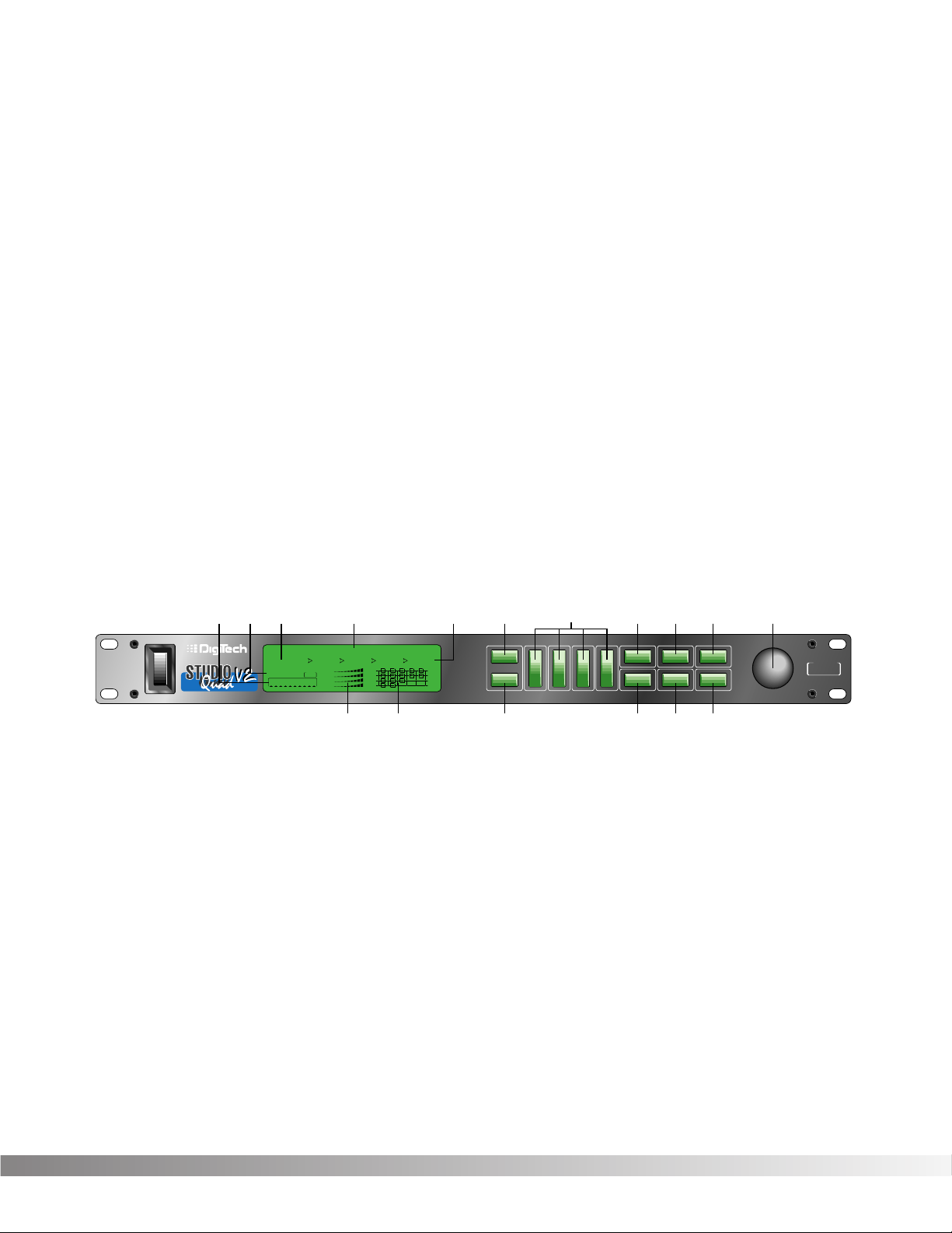
The layout of the Studio Quad V2’s front panel is simple and straightforward. Figure 1-1 shows the various parts of
the Studio Quad V2.
Figure 1-1 Front Panel
1) DISPLAY — The Studio Quad V2’s large custom display is where you get most of the information you need to
move around the operating system. The display has several important sections that you need to understand when
you use the Studio Quad V2. They are:
1a) Program Number Indicator — These three large digits in the upper left corner of the display indicate
which Program is currently selected.
1b) Factory / User Indicators — Directly below the Program number are the Factory and User Program indica-
tors. These indicators also include a CHANGED icon to tell you whether the Program has been modified but
not stored in memory. Factory Programs can be modified but must be stored in a User Program location since
Factory Programs cannot be overwritten.
1c) Page Indicators — The bottom left corner of the display is occupied by the Page indicators. They display
the number of Pages available and the Page which is currently selected. These icons only appear in the FX
Edit and Utilities modes.
1d) Information Line — This row of 24 characters (top line of the display) is the Information line. It gives
more detailed information about specific functions and items, and contains things like Program names,
Parameter names, and Utility or auxiliary information.
*(24)5x8PixelCharacters*
IN 4
IN 3
IN 2
IN 1
%kHz
mSec
FACTORY PRG MODIFIED
MIDI
CHANGED
LEVEL 4
LEVEL 3
LEVEL 2
LEVEL 1
OUT 4
OUT 3
OUT 2
OUT 1
CLIP
CLIP
CLIP
CLIP
USER PRG MODIFIED
FX EDIT PAGE
12345678910
188
••8
%kHz
mSec
CHANGED
%kHz
mSec
CHANGED
%kHz
mSec
CHANGED
1
UTILITY PAGE
MODIFIERS
••8 ••8 ••8
2 3 4
Next Page
Utility
In Levels
Bypass
Prev Page
Store
1
234
FX Edit
Program
CompareCompareCompare
Auto LevelsAuto LevelsAuto Levels
4 IN 4 OUT MULTI-EFFECTS PROCESSOR
S-DISC
™
PROCESSING
1a 1d 1e1b1c 2 4 579 11
3
1f 1g 6810
S-DISC
™
PROCESSING

4
Section 1 — Setting Up
Studio Quad V2 User’s Manual
1e) Parameter Data Sections — There are four Parameter Data sections in the display. They are immediately
below the Information line, and correspond with the <1> through <4> buttons on the front panel. Each
section displays the current value of the indicated Parameter. Each section also has an arrow that shows
which Parameter in the display is selected.
A CC indicator in each group tells whether the indicated Parameter is set up to be continuously controlled
( «continuous control» includes internal LFOs, dynamic modifiers, and MIDI continuous controller data).
Directly below each section is a CHANGED indicator that lights to indicate that the Parameter has been
changed but not stored.
1f) Input Level / Clip Meters — The bottom center of the display is occupied by the Input Level and Clip
meters. These meters show the input level of each channel, and use a peak detector action to display the
highest levels at the inputs. The Clip indicator at the end of each meter shows whether the input signal is
being clipped at the analog input section (pre-digital).
1g) Effect Routing Matrix — The Effect Routing Matrix shows the signal flow of the currently selected
Program. This matrix includes boxes that represent each effect module along with lines that indicate how
those effects are connected to inputs, outputs and each other. If an effect module is bypassed, a line
appears through that module’s box in the Matrix.
When in FX Edit mode, the box that represents the currently selected effect module will flash. Likewise the
Modifier module flashes the MODIFIER indicator, the Input Mode module flashes the Input Routing indicators and the Output Mode module flashes the Output Routing indicators.
2) PROGRAM BUTTON — Selects Program mode for Program selection. The Data Wheel is used to select a
program for loading. The Program button can also be used to toggle between the User or Factory Program
Banks. The active Program Bank is shown in the display by the Factory / User indicators (see item 1b).
This button is also used to access the Compare mode. See pg. 13 for more information.
3) FX EDIT BUTTON — Selects FX Edit mode for Program modification. If you continue to press this button, you
will scroll through each individual effect module, the Modifiers module and the Input/Output modules.
4) PARAMETER BUTTONS — The Parameter buttons <1> through <4> are used to select the Parameter or
Utility item you want to edit. In Program mode, they can also be used to enter the FX Edit mode’s 1st through
4th module.
5) PREV PAGE BUTTON — Scrolls to the previous Page in the Parameter list. Note that the Page indicators
change to reflect the currently selected Page number in the Parameter list.
6) STORE BUTTON — The <STORE> button is used to store user Programs in memory for later recall.
7) NEXT PAGE BUTTON — Scrolls to the next Page in the Parameter list. Note that the Page indicators change
to reflect the currently selected Page number in the Parameter list.
 UTILITY — Selects the Utility mode where global functions such as Screen Contrast, MIDI Channel, Program
Maps, SysEx Channel, SysEx Dumps, Program AutoLoad and Reset can be accessed.
9) IN LEVELS — This button is used to access both the automatic and manual input leveling controls. For more on setting
input levels, see pg. 29.
10) BYPASS — Bypasses all the effects in the Studio Quad V2.
11) DATA WHEEL — The Data Wheel lets you scroll through Programs and change Parameters values.
5
Section 1 — Setting Up
Studio Quad V2 User’s Manual
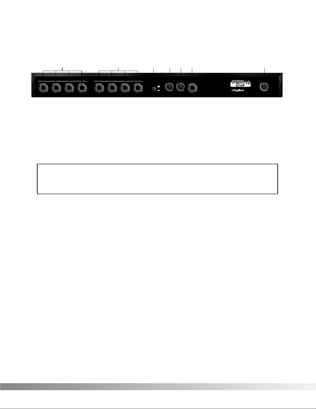
REAR PANEL CONNECTIONS
The layout of the Studio Quad V2’s simple and straightforward rear panel is illustrated in Figure 1-2.
Figure 1-2 Rear Panel
1) AUDIO INPUTS — These four 1/4” inputs can be used for several different combinations of input configura-
tions. The Input Configuration module of each Program defines how each Input is used. See pg. 11 for more info.
2) AUDIO OUTPUTS — The Studio Quad V2’s outputs can also be configured in many different ways. These settings are found in the Output Configuration module of each Program. See pg. 11 for more info.
3) OUTPUT LEVEL SWITCH — Selects whether the signal is nominally output at line level (-10 dB) or at professional level (+4).
4) MIDI IN — MIDI data is received at this port. When MIDI data is received, the MIDI indicator in the display flashes on and off.
5) MIDI OUT / THRU — Merges MIDI data generated by the Studio Quad V2 with MIDI data received at the input.
Please see pg. 31 for more information.
6) FOOTSWITCH — This jack allows connection of the DigiTech FS300 3-button footswitch or any shorting-type
footswitch. If using the DigiTech FS300, button 1 increments through Programs, button 2 decrements through
Programs, and button 3 bypasses the Studio Quad V2’s effects. When using any other single momentary switch
device, the switch acts as a Bypass.
NOTE: The footswitch must be plugged in on power up in order for the Studio Quad V2 to detect which type
of switch is being used.
7) POWER INPUT — Connect the included power supply to this jack. It is a 4-pin DIN connector. Use only the
DigiTech PS0920 power supply with the Studio Quad V2.
MAKING CONNECTIONS
Because of its flexibility, the Studio Quad V2 can be connected in several different ways to meet the requirements of
specific applications. The following diagrams offer some ways the Studio Quad V2 can be connected.
IN LINE
The Studio Quad V2 can be connected between a line level instrument output (such as keyboards, recording decks,
etc.) and a line level input (such as mixing console inputs). This method is called the «in-line» method because the
Studio Quad V2 is connected directly in the audio path of the source. When you use the in-line method, the master
wet-to-dry effects mix is controlled from the Studio Quad V2 operating system. Cable routings for this method look
like Figure 1-3:
WARNING: Make sure the Studio Quad V2’s audio levels are all down before changing the setting of this switch.
Also, be sure you know which setting is best for your particular equipment setup, as setting this switch to +4 can
overload the inputs of some line-level equipment. DigiTech is not responsible for any
damage to speakers or components due to misuse of this switch.
MANUFACTURED IN THE USA BY
SALT LAKE CITY, UTAH
INPUTS
1234
OUTPUTS
1234OUTPUT LEVEL
FOOTSWITCH
POWER
9VAC 2.2A
MIDIINMIDI OUT/
THRU
-10
+4
3 456 712
6
Section 1 — Setting Up
Studio Quad V2 User’s Manual
Figure 1-3 In-Line Connection
EFFECTS LOOP
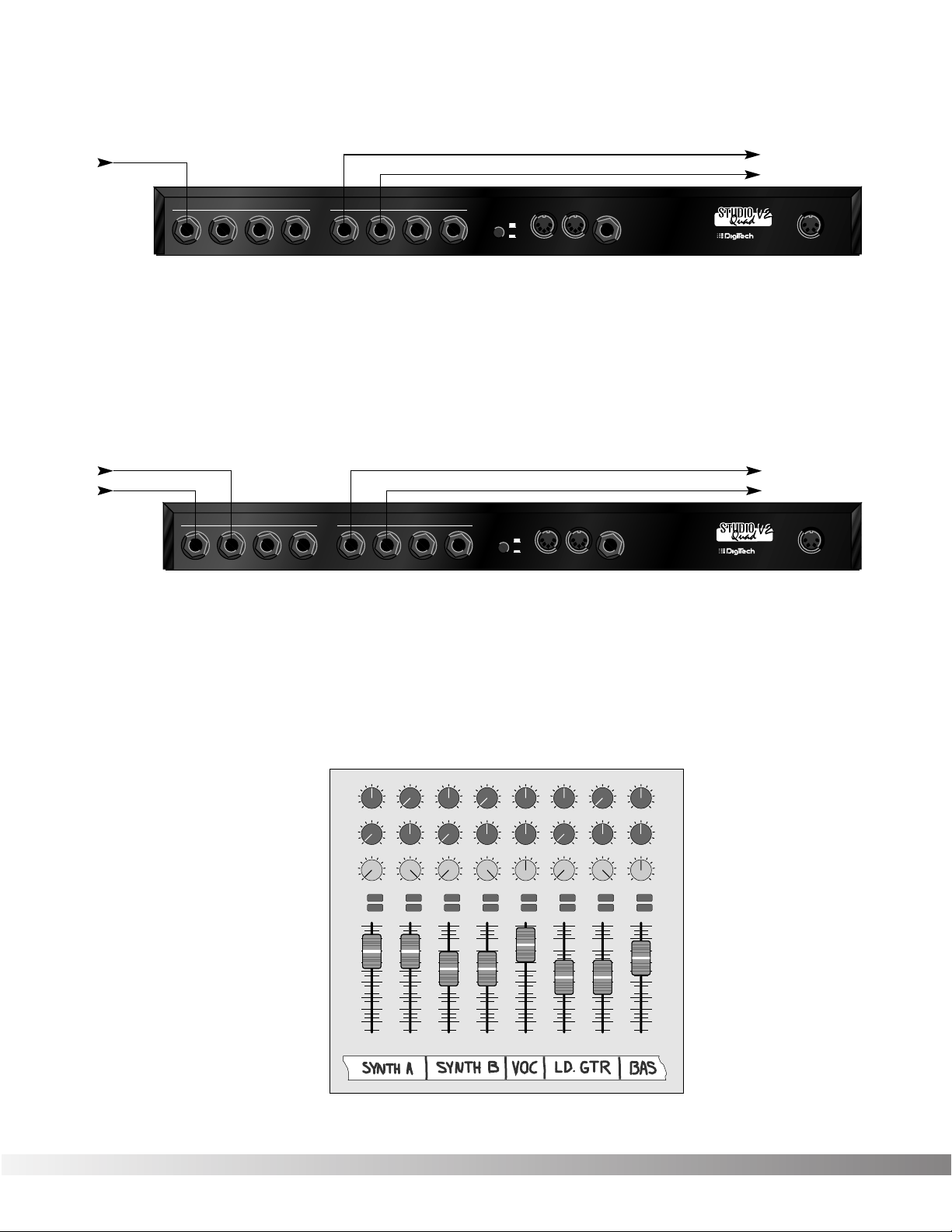
This application uses the Studio Quad V2 in an effects loop of a mixing console. In this application, the source is
routed directly to the mixer channel input(s). From there, the Studio Quad V2 gets its source audio from the console’s auxiliary send, and mix levels are controlled directly from the console. Figure 1-4 shows a common recording
studio or live sound reinforcement setup for effects processing with a console.
Figure 1-4 Effects Loop Configuration
Figure 1-5 shows an example of a typical stereo effect setup as seen from the console, and shows how to handle
both true stereo and mono input signals using two auxiliary sends.
This is the method of choice in many recording applications because of the impressive realism and depth of texture
that it produces. While it is slightly more complicated to set up and requires twice as many auxiliary sends, stereo
effects (particularly reverbs) improve dramatically in imaging and spaciousness.
Figure 1-5 Setting up a mixer’s aux sends for true stereo operation
Pan
Mute
-10
0
+5
+10
-20
-30
—∞
-5
L / R
Mute
L / R
Mute
L / R
Mute
L / R
-5
-4
-3
-2
-1
0
+1
+2
+3
+4
+5
Pan
-5
-4
-3
-2
-1
0
+1
+2
+3
+4
+5
Pan
-5
-4
-3
-2
-1
0
+1
+2
+3
+4
+5
Pan
-5
-4
-3
-2
-1
0
+1
+2
+3
+4
+5
Pan
-5
-4
-3
-2
-1
0
+1
+2
+3
+4
+5
Pan
-5
-4
-3
-2
-1
0
+1
+2
+3
+4
+5
Pan
-5
-4
-3
-2
-1
0
+1
+2
+3
+4
+5
Pan
-5
-4
-3
-2
-1
0
+1
+2
+3
+4
+5
1234
-10
0
+5
+10
-20
-30
—∞
-5
-10
0
+5
+10
-20
-30
—∞
-5
-10
0
+5
+10
-20
-30
—∞
-5
Mute
L / R
5
-10
0
+5
+10
-20
-30
—∞
-5
Mute
L / R
6
-10
0
+5
+10
-20
-30
—∞
-5
Mute
L / R
7
-10
0
+5
+10
-20
-30
—∞
-5
Aux 1
0
2
46
8
10
Aux 2
0
2
46
8
10
Aux 1
0
2
46
8
10
Aux 2
0
2
46
8
10
Aux 1
0
2
46
8
10
Aux 2
0
2
46
8
10
Aux 1
0
2
46
8
10
Aux 2
0
2
46
8
10
Aux 1
0
2
46
8
10
Aux 2
0
2
46
8
10
Aux 1
0
2
46
8
10
Aux 2
0
2
46
8
10
Aux 1
0
2
46
8
10
Aux 2
0
2
46
8
10
Aux 1
0
2
46
8
10
Aux 2
0
2
46
8
10
Mute
L / R
8
-10
0
+5
+10
-20
-30
—∞
-5
Aux Send 1
Aux Send 2
Pan Control
MANUFACTURED IN THE USA BY
SALT LAKE CITY, UTAH
INPUTS
1234
OUTPUTS
1234OUTPUT LEVEL
FOOTSWITCH
POWER
9VAC 2.2A
MIDIINMIDI OUT/
THRU
-10
+4
To Mixer Stereo Aux Return (L)
To Mixer Stereo Aux Return (R)From Mixer Aux Send 1
From Mixer Aux Send 2
MANUFACTURED IN THE USA BY
SALT LAKE CITY, UTAH
INPUTS
1234
OUTPUTS
1234OUTPUT LEVEL
FOOTSWITCH
POWER
9VAC 2.2A
MIDIINMIDI OUT/
THRU
-10
+4
To Amplifier or Mixer
From Instrument or Direct Source
To Amplifier or Mixer
7
Section 1 — Setting Up
Studio Quad V2 User’s Manual
REMEMBER: When you use this method to process stereo sources such as keyboards, the auxiliary sends on
your console should be set up exactly opposite one another, as shown on channels 1 and 2 of Figure 1-5. Note
that the left channel is sent to Aux 1, while the right channel is sent to Aux 2. When using mono sources like
vocals and bass guitar, send equal levels from both Aux 1 and Aux 2 to maintain proper soundfield balance of
the effects, as shown on channels 5 and 8.
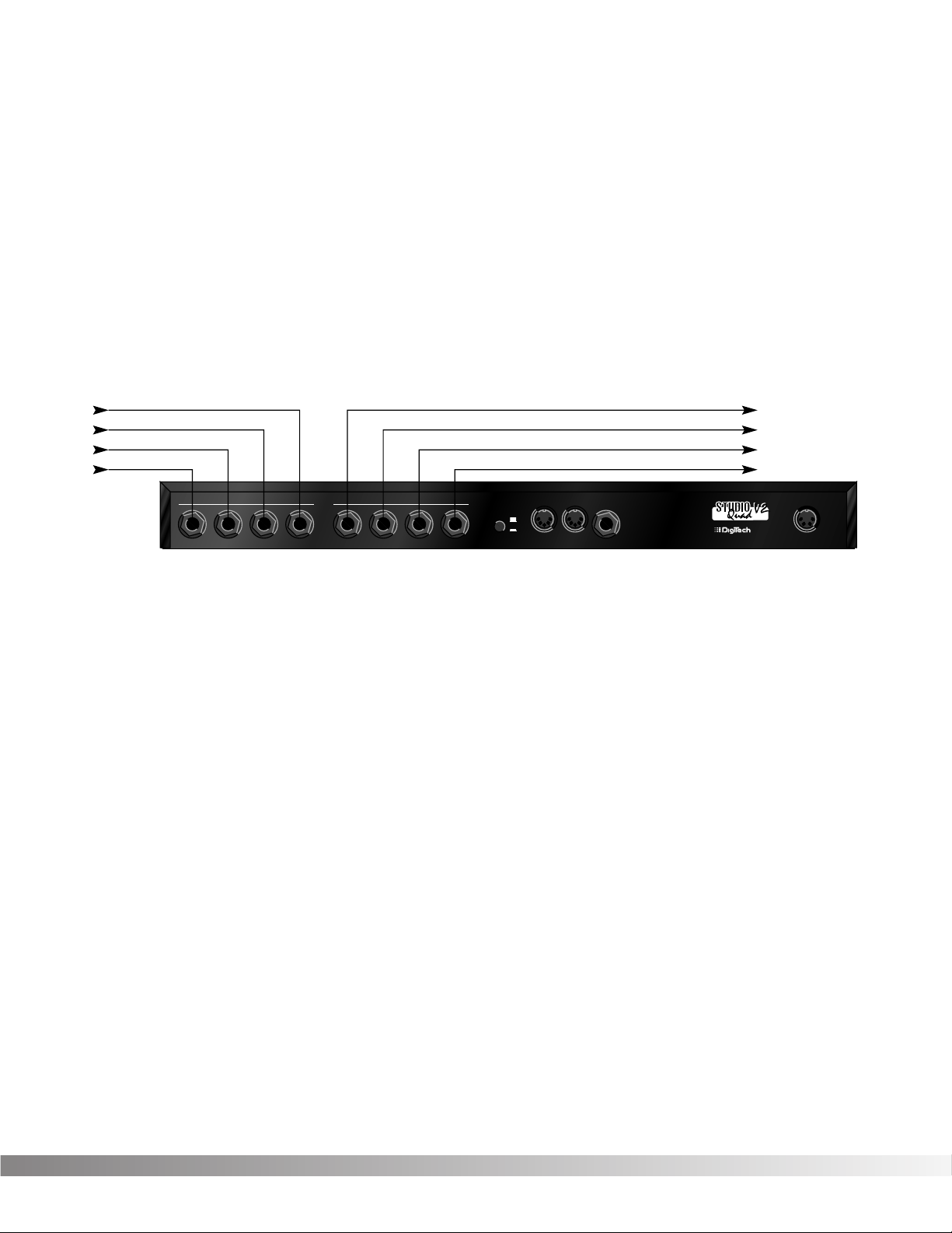
PARALLEL EFFECTS
Another application for the Studio Quad V2 allows you to independently process four discrete signals simultaneously. This method also utilizes the effects loops of your console, and since each effect has a mono input, the auxiliary
sends can be set up in a much more straightforward way. Figure 1-6 shows how to connect the Studio Quad V2 for
this application.
Figure 1-6 Quad Mono Input / Dual Stereo Output Configuration
Using this method, you could use channel 1 for a long vocal reverb, channel 2 for a short gated snare drum reverb,
channel 3 for lead guitar delay, and channel 4 to thicken keyboard instruments with a detuner. This method also
offers the flexibility of running different channels in-line or in an effects loop.
REMEMBER: Outputs can be configured any way you like, so don’t let any of this input / output stuff scare
you.
A WORD ABOUT BYPASS
Because of its flexibility, the Studio Quad V2 can be connected in several different ways to meet the requirements of
many specific applications. However, the definition of Bypass may change, depending on the application. The Studio
Quad V2 features Application Specific Bypassing so that the Studio Quad V2 functions appropriately in nearly every
application. When Bypassed, the Studio Quad V2 simply switches the Effects in that Program OFF, but the Dry
Levels defined in that Program remain untouched. If the effects are all wet (no Dry Level), the Bypass function effectively Mutes the Studio Quad V2. If the Dry Level is up, then the Studio Quad V2 passes the original signals through
without processing. A line through the modules in a Effect Configuration Matrix indicate that the module is
Bypassed.
MANUFACTURED IN THE USA BY
SALT LAKE CITY, UTAH
INPUTS
1234
OUTPUTS
1234OUTPUT LEVEL
FOOTSWITCH
POWER
9VAC 2.2A
MIDIINMIDI OUT/
THRU
-10
+4
To Mixer Stereo Aux Return 2 (L)
To Mixer Stereo Aux Return 2 (R)
To Mixer Stereo Aux Return 1 (L)
To Mixer Stereo Aux Return 1 (R)
From Mixer Aux Send 3
From Mixer Aux Send 4
From Mixer Aux Send 1
From Mixer Aux Send 2

8
SECTION 2 — BASIC FUNCTIONS OF THE STUDIO QUAD V2
GETTING AROUND THE OPERATING SYSTEM
The menu structure of the Studio Quad V2 has been specially designed to be easy to use. The display shows the
information you need, but to make things even easier for you, illumination of the front panel buttons offers additional operating information.
The front panel buttons give you information in one of two ways:
1) If the button is DIMLY lit, its function is INACTIVE. Pressing a dimly lit button causes it to light brightly and
its function becomes the active item in the display. If the DIMLY lit button doesn’t light after you press it,
the button is unavailable.
2) If the button is BRIGHTLY lit, its function is ACTIVE. Pressing an active button (other than the
<PROGRAM> button) reselects the already active item in the display.
PROGRAM MODE — Program mode allows you to scroll through the Factory and User Programs using the Data
Wheel. When the Studio Quad V2 is turned on, it sets itself to Program mode. Program mode is active when the
<PROGRAM> button is lit and a Program name is present on the Information line (top line) of the display. You can
toggle between Factory or User Programs by pressing the <PROGRAM> button when it is lit. The FACTORY PRG
or USER PRG indicator will be displayed according to which bank is selected. In this mode, all other buttons on the
front panel are dim or off.
To select a Program, do the following:
• Make sure Program mode is selected. If the <PROGRAM> button is dim, press <PROGRAM> once to return
to Program mode.
• Use the <PROGRAM> button to select the Program bank (Factory or User). Each successive press of the
<PROGRAM> button toggles between the Factory and User bank of Programs.
• Using the Data wheel, scroll to the Program you want to hear.
The selected program is immediately autoloaded. The AutoLoad feature can be turned off, allowing you to view a
program before actually loading it. See pg. 33 for further details.
FX EDIT MODE — This mode allows you to edit:
1) FX Modules,
2) the Modifier Module,
3) the Input Mode Module, and
4) the Output Mode Module of your Programs.
Use the <FX Edit> button to enter the FX Edit mode and then to select the next module for editing.
HINT: If you look at the Effect Routing Matrix while you press the FX Edit button, the currently selected module will flash. The Studio Quad V2 uses Pages to navigate within an effect. A Page is a group of up to four effect
Parameters that appear on the screen at one time. To move through the Pages in a Program, use the <NEXT
PAGE> and <PREV PAGE> buttons. Note that as you scroll through the Pages, the Page indicator in the lower
left corner of the display changes to show the currently displayed Page.
SELECTING FX TYPES AND DEFAULTS
The Studio Quad V2 has made custom digital signal processing easier than ever by giving you access to a complete
library of professionally developed effects settings. Page one of every FX Module allows you to:
1) Bypass that effect module
2) Select an effect Type (Chorus, Reverb, Delay, etc.)
3) Select a Default for the selected effect Type
Section 2 — Basic Function of the Studio Quad V2
Studio Quad V2 User’s Manual
9
The Default parameter allows you to select one of several effect settings stored in the Studio Quad V2’s library. For
example, there are 8 Dual Delay defaults to choose from. All Factory Programs use these Default settings. So, if you
like the Delay that is being used in Factory Program 62, simply locate page one of the FX Module, then use the <4>
button and the Data Wheel to recall the default (which happens to be A1-Pingpong1) in your new program. This
eliminates the need to copy all those parameters from one location to the other. It also gives you several starting
places so you can get as close as possible to the custom sound you are trying to create. Once you edit one of the
parameters in the FX Module, the default name is replaced with the word «Custom». This means that a default setting has been customized by the user or changed by real-time Modifiers for that program.
NOTE: There are two Banks available for the defaults, Bank A and Bank B. Effects stored in bank A contain the dry
signal for typical in-line applications. Effects in bank B do not contain the dry signal, and boosts the effect
level so it can be used with a mixing console’s effect loops . EQ, Panner, Noise Gate, and Tremolo do not
contain Dry level controls and therefore do not have a bank B available.
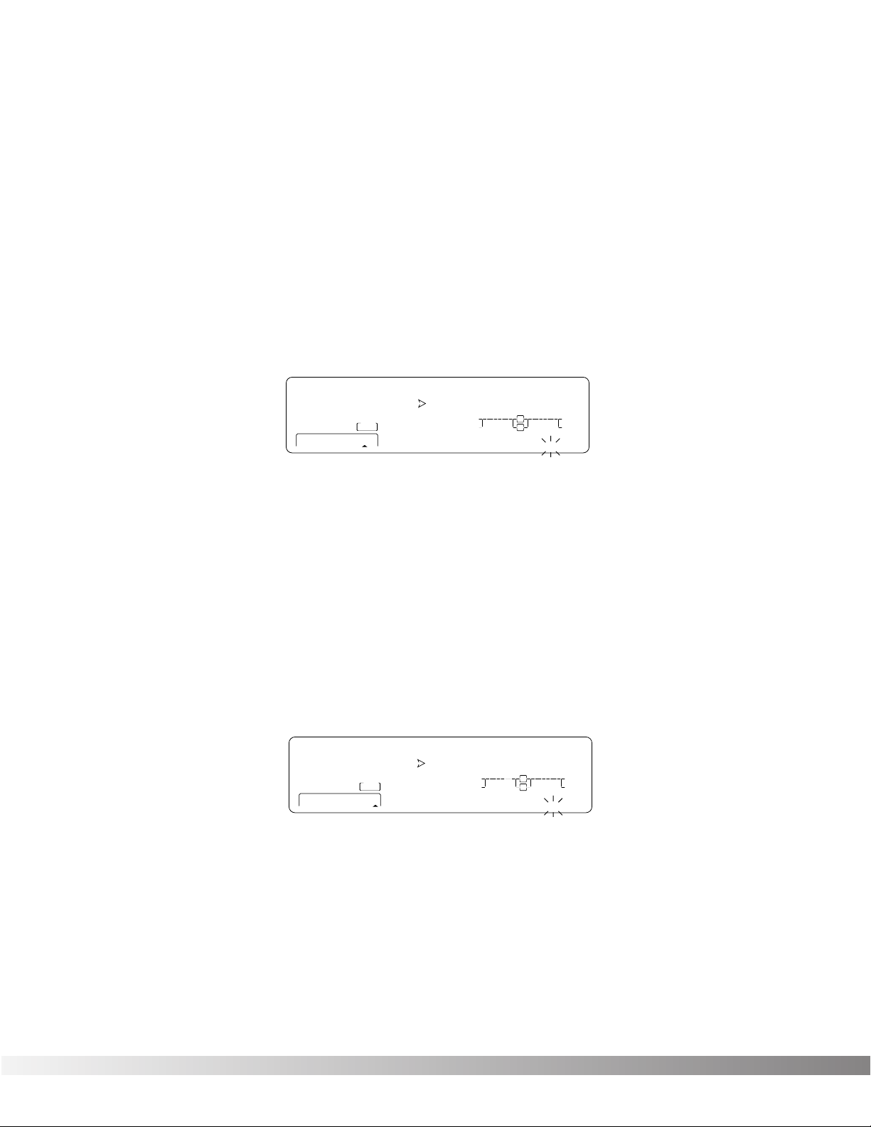
MODIFYING FX MODULE PARAMETERS EXAMPLE
Let’s modify an effect Parameter. Factory Program 139 uses a quad delay with a delay time of 700 milliseconds. The
tap percentages are set to DlyA = 25%, Dly B =50%, Dly C =75%, and Dly D =100%, which gives you evenly spaced
delay taps. But suppose they’re too slow to fit the tempo of a piece of music you’re composing. With most effects
units, you’d have to recalculate each delay tap individually, but the Studio Quad V2 makes it simple:
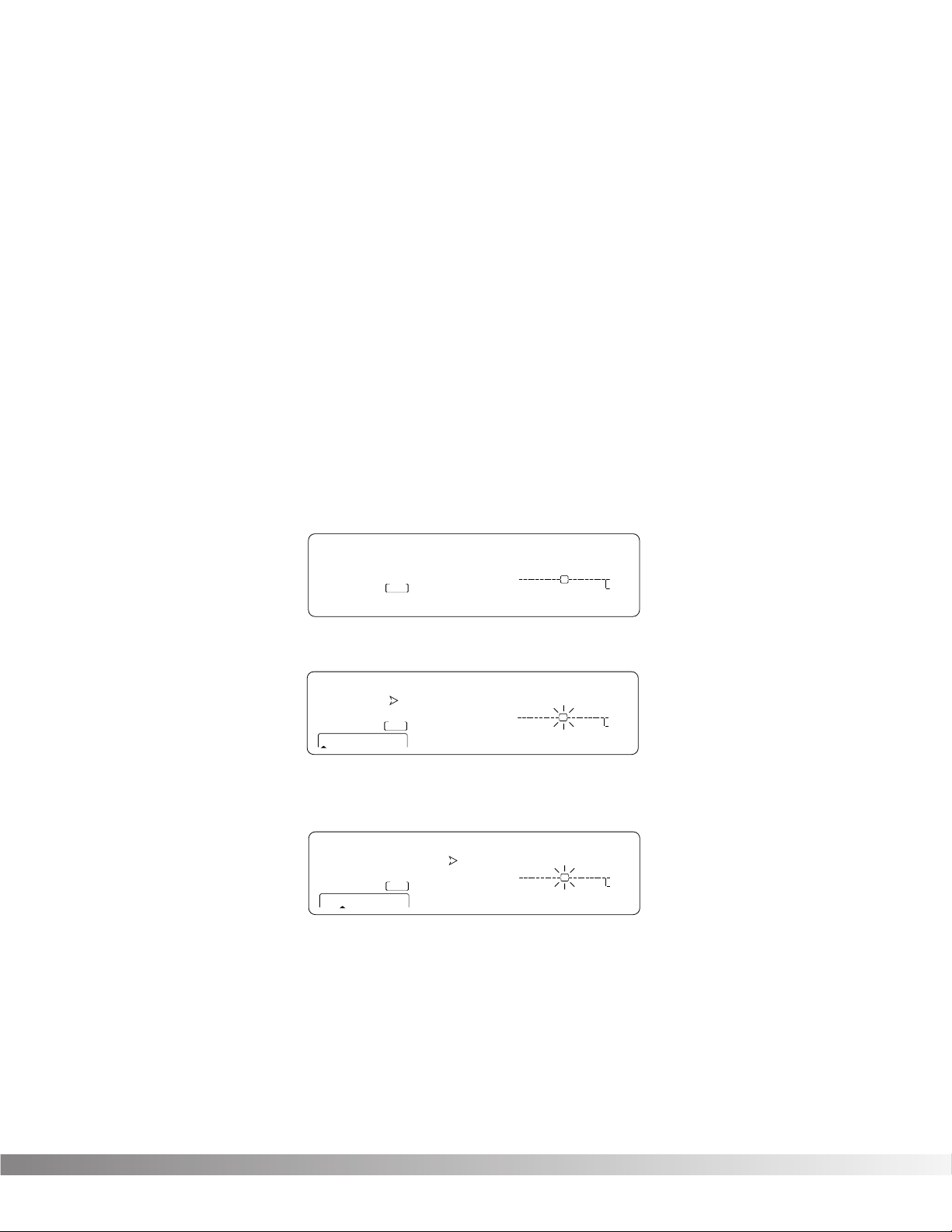
• If you’re not already there, switch to Program mode and use the Data wheel to scroll to Factory Program 139.
The display reads:
• Press <FX EDIT>. Note the current module being edited is flashing in the Effect Routing Matrix. The display
reads:
• Press <NEXT PAGE> twice. Position 2 of the Information line shows that the current delay time setting is 700
milliseconds. Remember that the total delay time shown in the display is divided among the delay taps in the
Module. The display reads:
• Use the Data Wheel to decrease the delay time. Both the Store button illuminates and the CHANGED icons
turn on indicating that the Program has been modified.
• Press the <Program> button to return to Program Mode, or continue in Edit Mode by continuing to press the
<FX EDIT> button.
NOTE: Make sure you store any changes you want to save before exiting the edit mode. See pg. 13 for more infor-
mation.
Section 2 — Basic Function of the Studio Quad V2
Studio Quad V2 User’s Manual
Quad Delay
139
FACTORY PRG
— CHANGED
USER PRG
— CHANGED
FX EDIT PAGE
1 2 3 4
%kHz
1 34
On Off 2
m
LEVEL 1
™
S-DISC
PROCESSING
LEVEL 2
LEVEL 3
LEVEL 4
%kHz
m
IN 1
IN 2
IN 3
IN 4
MODIFIERS
%kHz
m
SecSecSec
OUT 1
OUT 2
OUT 3
OUT 4
139
FACTORY PRG
— CHANGED
USER PRGUSER PRG
— CHANGED
FX EDIT PAGE
UTILITY PAGE
12 5678910
34
Fx:Quad Dly PingPong
C
C
1 2 3 4
On
MIDI
™
S-DISC
PROCESSING
C
C
%kHz
FUL 888 b 1
m Sec
CHANGED CHANGED
LEVEL 1
LEVEL 2
LEVEL 3
LEVEL 4
C
C
%kHz %kHz
CLIP
IN 1
CLIP
IN 2
CLIP
IN 3
CLIP
IN 4
m
C
C
DIGITAL CLIP
MODIFIERS
%kHz
m
SecSecmSec
OUT 1
OUT 2
OUT 3
OUT 4
139
FACTORY PRG
— CHANGED
USER PRGUSER PRG
— CHANGED
FX EDIT PAGE
UTILITY PAGE
12 5678910
34
Delay Time FdBck TapIt
C
C
1 234
On
MIDI
™
S-DISC
PROCESSING
C
C
%kHz
700 35 __
m Sec
CHANGED CHANGED
LEVEL 1
LEVEL 2
LEVEL 3
LEVEL 4
C
C
%kHz %kHz
CLIP
IN 1
CLIP
IN 2
CLIP
IN 3
CLIP
IN 4
m
C
C
DIGITAL CLIP
MODIFIERS
%kHz
SecSecmSec
m
OUT 1
OUT 2
OUT 3
OUT 4
10
EFFECT & INPUT / OUTPUT CONFIGURATIONS
The Studio Quad V2’s ability to accommodate a number of different input and output routing configurations makes it
an extremely useful and flexible tool for many different applications.
Programs 101 through 112 in the Factory Program bank are all the FX module configurations available in the Studio
Quad V2. For diagrams of these 12 Effect Configurations, see pg. 38. When you find one that you like, you can save
it to a new User Program location for later use.
NOTE: Choosing an Effect Configuration does not define the input / output routing schemes or the actual effects
used within the configuration. This means that even one configuration can be used thousands of different
ways.
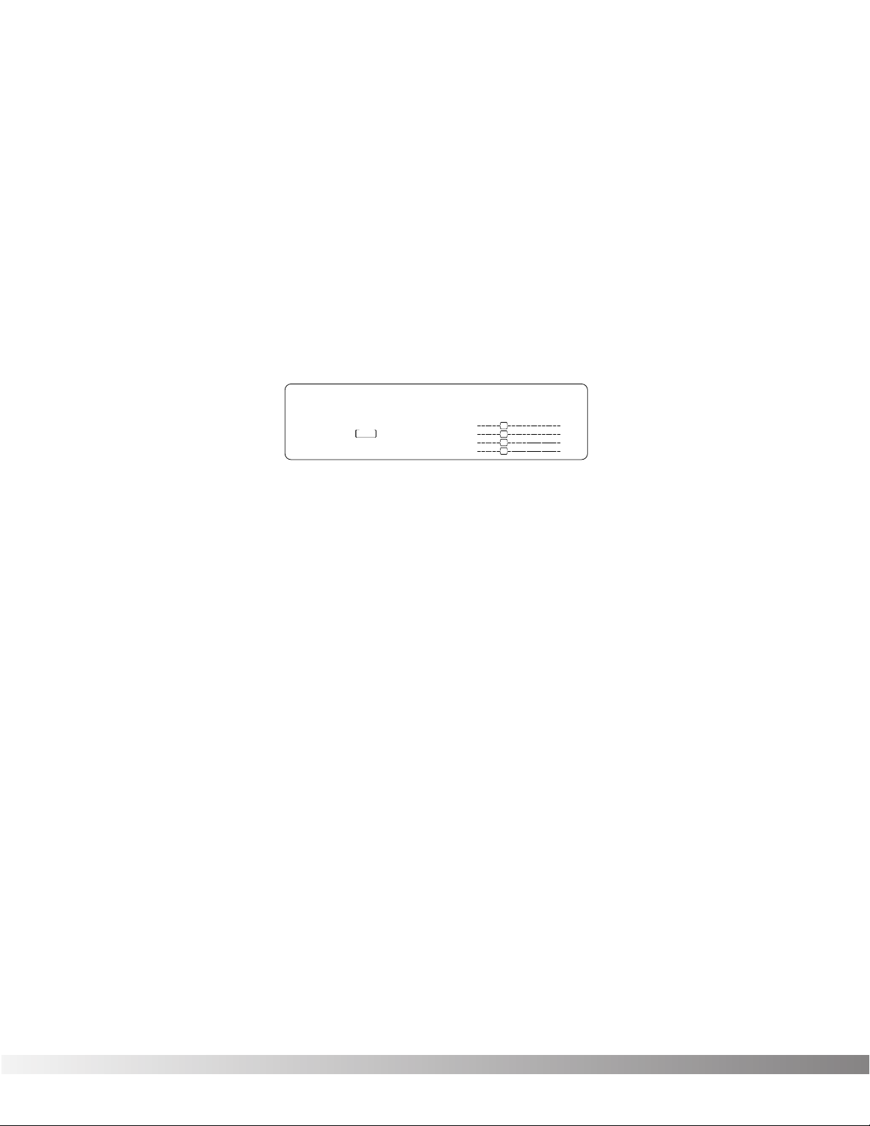
To select a new Effect Configuration, do the following:
• Scroll through Factory Programs 101 — 112 until you find a configuration you want to use. Let’s use Pgm. 101;
the display looks like this:
Next, select the input/output configuration you want to use:
• Press the FX Edit button 6 times. The input section of the Effect Routing Matrix begins flashing and the information line reads:
Input Mode: Quad Mono
• Use the Data Wheel to scroll through the 9 available input configurations.
• Press the FX Edit button one more time. The output section of the Effect Routing Matrix begins flashing and
the the information line reads:
Output Mode: Quad Mono
• Press parameter button <1>, then use the Data Wheel to scroll through the 9 available output configurations.
• Press parameter button <4>, then use the Data Wheel to to set the output level for the program.
NOTE: Make sure you store any changes you want to save before exiting the edit mode. See pg.13 for more
information.
USING MODIFIERS
Modifiers are unique tools that can be used to dramatically alter your sound based on information from signal amplitude,
the settings of a Low Frequency Oscillator (LFO) or MIDI Continuous Controller information.
Every Program in the Studio Quad V2 has a set of Modifiers. Up to 8 Modifier links can be assigned to control parameters. There are three types of Modifiers that can be linked to a parameter: MIDI CCs, LFOs, and Dynamic (signal
level dependent).
MIDI CCs — When you use MIDI CCs, the Studio Quad V2 responds to CC numbers 0-127 and CHP (channel
pressure or aftertouch). This means that you could assign your keyboard’s modulation or pitch bend wheel (or any
other MIDI CC device) to control effect Parameters.
For example, you can have a synth’s modulation wheel (usually MIDI CC#1) control the in level of a reverb and chorus in one program while the delay feedback is controlled in another.
Section 2 — Basic Function of the Studio Quad V2
Studio Quad V2 User’s Manual
101
FACTORY PRG
— CHANGED
USER PRG
— CHANGED
FX EDIT PAGEFX EDIT PAGE
UTILITY PAGEUTILITY PAGE
1 2 5 6 7 8 9 10
3 4
Cfg: 1 (4,4,4,4)
C
C
1 234
Off
CHANGED
MIDI
™
S-DISC
PROCESSING
C
C
%kHz
888 888 888
m Sec
CHANGED CHANGED CHANGED
LEVEL 1
LEVEL 2
LEVEL 3
LEVEL 4
C
C
%kHz %kHz
CLIP
IN 1
CLIP
IN 2
CLIP
IN 3
CLIP
IN 4
m
C
C
DIGITAL CLIPDIGITAL CLIP
MODIFIERS
%kHz
m
SecSecmSec
OUT 1
OUT 2
OUT 3
OUT 4

11
LFOs — When you use LFOs, Parameter values can be controlled automatically between a defined minimum and
maximum setting at a rate set by the user. The Studio Quad V2 has 2 user definable LFOs in each program that can
be assigned to any Parameter.
For example, you can create an auto panner without using an auto panner module. Simply link an effect’s output pan
parameter to the LFO modifier and the LFO will move that parameter back and forth. This modifier can be a very
useful weapon in the ongoing battle of new sound creation. There are two LFOs available in each program that can
use unique speeds and waveforms.
Dynamic Modifiers — When you use Dynamic Modifiers, the Parameter values are controlled in relation to the
dynamics of the input signal. The possibilities are nearly endless, and they cannot be duplicated using any other
method.
For example, you could link the Dynamic Modifier of a Program to control a chorus level. It doesn’t sound like much
on paper, but imagine the expressiveness of this type of effect on a vocal part. As the dynamics of the music
increase, the chorus becomes less apparent. Ease up on the vocal a little and the chorus increases. ALL IN REAL
TIME!
NOTE: Linking a Modifier to a Parameter causes the Parameter to change as if you were changing it using the Data
Wheel. The only difference is that the <Store> button and PROGRAM CHANGED indicators do not light.
Therefore, the Default name may display ‘Custom’ if a Parameter is consistently being changed by a
Modifier. Storing the Program will store these new Parameter values.
LINKING A PARAMETER TO A MODIFIER
To link a Parameter to a Modifier, do the following:
• Press <FX EDIT> until you readh the Modifiers Edit Mode. The display looks something like:
Notice that the modifiers icon in the bottom right corner of the display begins flashing.
• Pressing the <NEXT PAGE> and <PREV PAGE> keys will scroll through Pages 1-8 to select which of the 8
Modifier Links you want to use.
• Use the Data wheel to scroll to the Parameter you want assigned to Modifier link #1. As you scroll, the MIN
and MAX values for each Parameter show in the display.
NOTE: The MUTE and THRU effect types do not have any Parameters to connect to, so they will not appear
in the parameter list.
• Press <3> to select the Minimum Value Parameter.
• Use the Data wheel to set the minimum Parameter to the value you want when the controller is in the minimum position. These values vary because different Parameters have different value units, such as milliseconds
or percent.
• Press <4> to select the Maximum Value Parameter.
• Use the Data wheel to set the maximum Parameter to the value you want when the controller is in the maximum position.
Section 2 — Basic Function of the Studio Quad V2
Studio Quad V2 User’s Manual
Mod-1: Select parameter
C
C
1 234
1
FACTORY PRG
— CHANGED
— CHANGED
PROCESSING
UTILITY PAGE
S-DISC
USER PRG
FX EDIT PAGE
12 5678910
34
%kHz
Off
m Sec
MIDI
LEVEL 1
™
LEVEL 2
LEVEL 3
LEVEL 4
m
C
C
DIGITAL CLIPDIGITAL CLIP
C
C
888 888 888
CHANGED CHANGED CHANGED
C
C
%kHz %kHz
CLIP
IN 1
CLIP
IN 2
CLIP
IN 3
CLIP
IN 4
MODIFIERS
%kHz
m
SecSecmSec
OUT 1
OUT 2
OUT 3
OUT 4
12
• Press <2> to select the Modifier Type Parameter.
• Using the Data wheel to scroll through the Modifier types: MIDI CC number 0 -127 and CHP (Channel
Pressure or Aftertouch), L — 1 (LFO1), L — 2 (LFO2), or DYN (Dynamic).
NOTE: Make sure you store any changes you don’t want to lose. See pg. 13 for more information
SETTING UP AN LFO OR DYNAMIC MODIFIER
To link an LFO to a parameter, do the following:
• Press <FX Edit> until you reach the modifiers edit mode. The modifiers icon begins to flash in the bottom
right corner of the screen.
• Use the <NEXT PAGE> and <PREV PAGE> keys to scroll to Page 9. The display reads:
• Press <1> and use the Data wheel to select which LFO you want to adjust.
• Press <2> and use the Data wheel to change the selected LFO’s waveform. You can select SINe, TRIangle,
SPecial1, SPecial2 or SPecial3. Refer to pg. 19 for Waveform information.
• Press <3> and use the Data wheel to adjust the speed of the LFO cycle.
The assigned Parameter now follows the modulating waveform of the LFO you selected. See pg. 19 for waveform
diagrams.
To link a Dynamic Modifier to a parameter, do the following:
• Press <FX Edit> until you reach the modifiers edit mode. The modifiers icon begins to flash in the bottom
right corner of the screen.
• To adjust the settings of the Dynamic Modifier, use the <NEXT PAGE> and <PREV PAGE> keys to scroll to
Page 10. The display reads:
• Press <2> and use the Data wheel to adjust LoThrs. This control sets the threshold above which dynamic
modification of the Parameter begins.
• Press <3> and use the Data wheel to adjust HiThrs. The HiThrs control sets the point at which maximum
Parameter modification occurs.
• Press <4> and use the Data wheel to select which input (1 — 4) you want the modifier to «listen» to, or follow.
Section 2 — Basic Function of the Studio Quad V2
Studio Quad V2 User’s Manual
1
FACTORY PRG
USER PRG
— CHANGED
FX EDIT PAGE
UTILITY PAGE
12 5678910
34
LFO WvFrm Speed
C
C
1 23
L-1
CHANGED
MIDIMIDI
™
S-DISC
PROCESSING
C
C
%kHz
5in ¡00 100
m Sec
CHANGED CHANGED
LEVEL 1
LEVEL 2
LEVEL 3
LEVEL 4
C
C
%kHz %
CLIPCLIP
IN 1
CLIPCLIP
IN 2
CLIPCLIP
IN 3
CLIPCLIP
IN 4
m
Hz
DIGITAL CLIPDIGITAL CLIP
MODIFIERS
%kHz
m
SecSecmSec
OUT 1
OUT 2
OUT 3
OUT 4
1
FACTORY PRG
USER PRG
— CHANGED
FX EDIT PAGE
UTILITY PAGE
12 5678910
34
Dyn LoThrs HiThrs In-Src
C
C
1 234
-12
CHANGED
MIDI
™
S-DISC
PROCESSING
C
C
%kHz
0 100 1
m Sec
CHANGED CHANGED
LEVEL 1
LEVEL 2
LEVEL 3
LEVEL 4
C
C
%kHz %kHz
CLIPCLIP
IN 1
CLIPCLIP
IN 2
CLIPCLIP
IN 3
CLIPCLIP
IN 4
C
C
DIGITAL CLIPDIGITAL CLIP
MODIFIERS
%kHz
m
SecSecmSec
OUT 1
OUT 2
OUT 3
OUT 4
m
Loading…
FAQ: Types of Manuals and Their Contents
DigiTech STUDIO QUAD V2 Manuals come in various types, each serving a specific purpose to help users effectively operate and maintain their devices. Here are the common types of DigiTech STUDIO QUAD V2 User Guides and the information they typically include:
- User Manuals: Provide comprehensive instructions on how to use the device, including setup, features, and operation. They often include troubleshooting tips, safety information, and maintenance guidelines.
- Service Instructions: Designed for technicians and repair professionals, these manuals offer detailed information on diagnosing and repairing issues with the device. They include schematics, parts lists, and step-by-step repair procedures.
- Installation Guides: Focus on the installation process of the device, providing detailed instructions and diagrams for proper setup. They are essential for ensuring the device is installed correctly and safely.
- Maintenance Manuals: Provide guidance on routine maintenance tasks to keep the device in optimal condition. They cover cleaning procedures, part replacements, and regular servicing tips.
- Quick Start Guides: Offer a concise overview of the essential steps needed to get the device up and running quickly. They are ideal for users who need immediate assistance with basic setup and operation.
Each type of DigiTech STUDIO QUAD V2 instruction is designed to address specific needs, ensuring users have the necessary information to use, maintain, and repair their devices effectively.
Related Instructions for DigiTech STUDIO QUAD V2:
1
LEGENDII
Manual User Guide: DigiTech LEGENDII (4X29YK, Upd.05.12.2024)
73
1020
235
2
GE4134
Operation & user’s manual DigiTech Turntable Operation & user’s manual (File: digitech-ge4134-operation-user-s-manual-5, 13.01.2025)
5
1443
217
4
WEAPON
Manual WEAPON (Other ePDF User Manual, #XS3P4A)
20
1154
185
6
CabDryVR
Owner’s manual DigiTech Music Pedal Owner’s manual (File: digitech-cabdryvr-owner-s-manual-17, 25th Jan 2025)
17
186
47
7
Hardwire SC-2
Owner’s manual User Guide: DigiTech Hardwire SC-2 (6CI85B, Upd.Sun 03.2025)
20
725
131
8
Scott Ian Black-13
Owner’s manual Scott Ian Black-13 (Other ePDF Guide, #7CUJ7D)
11
1426
286
Processor Devices by Other Brands:
|
TYAN TAHOE PLUS ATX Manual TAHOE PLUS ATX (Processor ePDF Manual, #92R79O) 1 31 Dec 2024 | 28 |
|
|
Crest Audio CV301 Specifications Processor #9W7882 Product Information 12 Apr 2025 | 2 |
|
|
Rane PI 14 Datasheet Rane Processor Datasheet (File: rane-pi-14-processor-4, Thursday 24-10-2024) Professional Audio Products Data Sheet 24 Oct 2024 | 4 |
|
|
HP D7171A — NetServer — LPr Using #8H6K47: D7171A — NetServer — LPr Desktop Using Using Ultra SCSI in your HP NetServer 03 Dec 2024 | 5 |
Categories:
DJ Equipment
Computer Hardware
Ultrasonic Jewelry Cleaner
Microphone
Computer Accessories
Extender
-
-
#1
Копался сегодня во всяких комнатахи шкафах на студии и на шел эти девайсы Genelec 1029,Digitech StudioQuad,покупал лет 7 назад …всё обновлялось и забыл про них,а тут попались на глаза. Включил мониторы послушал …надо менять подвесы явно всё старое, один драйвер не пашет.
Можно ли где то это востановить?(жалко выбрасывать на контроль то они ещё бы потрудились.)
Включил этот 4 канальный тревожный реверок Digitech StudioQuad и не увидел пресетов и выход его в раб режим не случился,заменил батарейку внутри ,не помогло..встаёт в ступор,поискал сегодня описание на него в инете может какието комбинации клавишь есть .чтобы вывести его из «Комы» нету….
Может ктонибудь сталкивался или знает чего делать?(выкидывать жалко):help:
-
-
#2
<div class=’quotetop’>QUOTE(\»СобакаНах\»)</div>
Включил этот 4 канальный тревожный реверок Дигитеч СтудиоQуад и не увидел пресетов и выход его в раб режим не случился,заменил батарейку внутри ,не помогло..[/b]
Я,конечно, не спец по сабжу, но он часом не на 127 вольт?
-
-
#3
попробуй по инету связаться с сервисом http://www.attrade.ru
хотябы по Digitech StudioQuad думаю, консультацию окажут. Во всяком случае наши киевские по телефону такие консультации дают…
А ремонт Genelec 1029…, был бы ты в Киеве,… но думаю если поискать, то и в Томске должны быть мастера по Hi- End акустике, эти и чёрта отремонтируют, правда могут и в «Таной» переделать, но это уже от энузиазма зависит.
Но,блин,сначала ник потом автар!!!!!!!!!!! Круто !!! Да и я тут попрыгаю…
-
-
#4
Originally posted by presly
Я,конечно, не спец по сабжу, но он часом не на 127 вольт?
Нет тут явно не с вольтажём дело,я его помню он работал от стандартной сети. Тут что то с заводскими пресетами,он грузится до определённого момента(по дисплею бегают фсяки фсяки),потом как компьютер зависает и не регагирует не на какие кнопки….:frown:
-
-
#5
Originally posted by presly
Я,конечно, не спец по сабжу, но он часом не на 127 вольт?
Нет тут явно не с вольтажём дело,я его помню он работал от стандартной сети. Тут что то с заводскими пресетами,он грузится до определённого момента(по дисплею бегают фсяки фсяки),потом как компьютер зависает и не регагирует не на какие кнопки….:frown:
-
-
#6
Originally posted by presly
Я,конечно, не спец по сабжу, но он часом не на 127 вольт?
Нет тут явно не с вольтажём дело,я его помню он работал от стандартной сети. Тут что то с заводскими пресетами,он грузится до определённого момента(по дисплею бегают фсяки фсяки),потом как компьютер зависает и не регагирует не на какие кнопки….:frown:
-
-
#7
<div class=’quotetop’>QUOTE(\»СобакаНах\»)</div>
он грузится до определённого момента(по дисплею бегают фсяки фсяки),потом как компьютер зависает и не регагирует не на какие кнопки….[/b]
Да тут, похоже, что-то сдохло, микросхема какя-нить. У меня подобная хрень была с Proteus 2000, в Америку отправляли плату менять. Хорошо, что на гарантии был. У товарища когда-то таким же макаром сдох ART SGE Mach 2, в своё время дороже «Жигулей» стоил, меняли какую-то микруху.
-
-
#8
Эх не хотелось бы конечно(( У меня ещё Apex эксайтер со сгоревшим операционником лежит,ваще аналогов найти ни кто не может (у нас в Мухосранске)
-
-
#9
Наконец процессор Digitech StudioQuad V2заработал,разобрался я с прблеммой Вот чего выискал
StudioQuad4
• How do I reset the Studio Quad 4 to factory settings?
To reset the Studio Quad 4, turn the power off, press and hold the #1 button while turning the power back on. After about 2 seconds, release the #1 button, and press the «program» button once. This will reset the entire unit.
Это правда для другого девайса,но сработало,всё запахало и отдал я его гитаристам(для голоса он слаб) ротари лесли хорусы и фленжера там очень даже ничего.:super2:
Спасибо всем кто проявил участие.
-
-
#10
<div class=’quotetop’>QUOTE(\»СобакаНах\»)</div>
Наконец процессор Digitech StudioQuad V2заработал,разобрался я с прблеммой[/b]
Ну слава Богу, что ничего не сдохло. Прими мои поздравления, чуваг! :beer:
-
-
#11
Originally posted by Alex_HS
Ну слава Богу, что ничего не сдохло. Прими мои поздравления, чуваг! :beer:
Спасибо:beer:
Теперь буду думать чего С Дженлюками делат и Апфексом.
-
-
#12
Продам Aphex C2 в отличном состоянии на запчасти СобакеНах 
-
-
#13
Бритый-Aphex 104 Aural Exciter Type C2-ентот?)))
-
-
#14
Ага rinka:
With Big Bottom 
-
-
#15
Да ну ладно))) Мне внего операционник (связно с питанием) в паяют и думаю он где нибудь будет дальше пылица)))
leonardovich683 — 20.02.2021
Процессор DigiTech Studio Quad (546$) имеет четыре входа и
четыре выхода. Может производить четыре эффекта одновременно из 12
имеющихся алгоритмов (ревербератор, задержка, хорус, фленджер,
фейзер, тремоло, смещение высоты тона, графический и
параметрический эквалайзер, гейт, имитатор вращения динамика,
компрессор). Максимальное время задержки 1,4 секунды. Есть 180
пресетных и 100 пользовательских пэтчей. АЦП 18-разрядные со
128-кратной передискретизацией, частота дискретизации 44,1 кГц,
внутренняя обработка 24-разрядная. Частотный диапазон от 20 Гц до
20 кГц, динамический диапазон 95 дБ. Истинная стереообработка и
независимая обработка каждого входа отдельным эффектом. Некоторые
алгоритмы требуют всей мощности процессора. Входы-выходы
симметричные, на джеках, переключаются между +4/-10 дБ. Возможна
автоматическая установка входного уровня. Есть разъем для педали и
два MIDI-разъема (In и Out/Thru). Восемь параметров модулируются:
по MIDI, LFO или в зависимости от уровня входного сигнала. Возможен
ввод темпа с передней панели. Устройство не имеет возможности
глобального (для всех пэтчей) отключения прямого сигнала. При
переключении пэтчей происходит пауза около четверти секунды, во
время которой не слышен в том числе и прямой звук.
Симптомы-При включении рандомная засветка сегментов дисплея.На
вращение валкодера и нажатие кнопок реакции,нет.Полное отсутствие
выходного сигнала.Напряжения и фильтрация +5V+15-15в норме.Причина
неработоспособности-разрядка литиевой батареи CR2032 питающей
микросхему EPROM ( Erasable Programmable Read Only Memory)
При отсутствии+3V с неё при включении не происходит загрузка
базового ПО в оперативную память процессора.Вооружаемся отвёрткой
Филипс (крестовая)и снимаем крышку.В левом переднем углу находим
батарею в стандартном зажиме.Меняем.Всё,кожух можно ставить на
место.Включаем девайс.На дислее снова мусор и цены на дрова в
Зимбабве..Это нормально.Теперь надо сделать аппаратный сброс
процессора..
1-Нажимаем и удерживаем кнопку выбора пресетов(1).
2-Включаем и выключаем кнопку Power.
3-После примерно 2 секунд отпускаем кнопку(1) и нажимаем кнопку
Program-Один раз!!
Это сбросит весь блок.
Благодарность за подсказку-Matty Dread из студии»King B Sound
System»из Hastings on the UK.И Дэйву Брауну(Dave Brown.).
Хотя в руководстве и на этикетке устройства указано, что в нем
нет деталей, обслуживаемых пользователем, мне было нечего терять
… так что …
Да..Ссылка на руководство пользователя..
Digitech Studio Quad V2
Посмотреть и скачать с Яндекс.Диска
disk.yandex.ru
Оставить комментарий
Популярные посты:
- Архив
Архив записей в блогах:
Очень, очень удобно, когда пенсионный возраст выше средней продолжительности жизни. Гадкие старики всю жизнь выплачивают взносы, а потом уходят по радуге, оставляя бабло уважаемым людям. То и дело натыкаюсь то в сети, то в коментах на примеры вида «а вот у меня деду 102 года и до сих …
Известная грантососка Чирикова подняла вой об арестах сососателей грантов. А как дела в Уфе? У нас не Москва. Уфа — деревня маленькая. Проверить вопли будет несложно… Что скажут местные грантососы? Активистов арестовали или нет? …
МОСКВА, 8 декабря. /ТАСС/. Рейс авиакомпании «Россия» Минеральные Воды — Санкт-Петербург совершил экстренную посадку в аэропорту Минвод из-за технических неполадок. Об этом ТАСС сообщили в оперативных службах.
Очень часто стали появляться сообщения о самолетных неисправностях… …
Всемирное антидопинговое агентство — WADA, не скрывая своего недовольства заявило, что организация поддерживает связь с Россией с целью получения ежегодного взноса в размере $ 1,26 млн., однако продолжающиеся ограничения в мировой банковской системе усложняют этот процесс. При этом в …
Не знаю кому как, а мне грузинская кухня пришлась по душе. Я, конечно, не очень экспериментировал с выбором блюд в общепитах (особенно в сравнении с Андреем bortnikau ), но различных хачапури и хинкали за время грузинского импровизированного теста шин Viatti умял немало. …