
Последние материалы для загрузки
В следующем списке представлены последние совместимые с E-MU 1616M PCIe материалы для загрузки.
Просмотр: Драйвер | Бета-версия драйвера | Приложение | Все
Все материалы для загрузки
Для получения полного списка загрузочных файлов, Вы можете вручную найти их в нашей базе данных.
Драйвер
E-MU PCIe Digital Audio System drivers
This download contains the original drivers and applications found on the E-MU PCIe Digital Audio System series of audio devices installation CD. For more details, read the rest of this web release note.
Показать сведения »
Дата выпуска:
14 Jul 11
Размер файла:
33.32 MB
Загрузка
Приложение
E-MU PCIe Digital Audio System Application
This download contains the original drivers and applications found on the E-MU PCIe Digital Audio System series of audio devices installation CD. For more details, read the rest of this web release note.
Показать сведения »
Дата выпуска:
14 Jul 11
Размер файла:
9.47 MB
Загрузка
Просмотреть все материалы для загрузки >
Digital Audio System
Owner’s Manual
E-MU 1616/1616M CardBus Digital Audio System 1

E-MU 1616/1616m CardBus
Digital Audio System
Owner’s Manual
© 2003 E-MU Systems
All Rights Reserved
Software Version: 1.81
E-MU World Headquarters
E-MU Systems
1500 Green Hills Road
Scotts Valley, CA
95066
USA
Europe, Africa, Middle East
Creative Labs
Ballycoolin Business Park
Blanchardstown
Dublin 15
IRELAND
E-MU Japan
Creative Media K K
Kanda Eight Bldg., 3F
4-6-7 Soto-Kanda
Chiyoda-ku, Tokyo 101-0021
JAPAN
2 Creative Professional

Table of Contents
1- Introduction ……………………………………………………….. 7
Welcome!……………………………………………………………………………………………………………… 7
The E-MU 02 CardBus Card ……………………………………………………………………………….. 7
E-MU MicroDock ………………………………………………………………………………………………. 7
E-MU 1616M System …………………………………………………………………………………………. 8
PatchMIx DSP …………………………………………………………………………………………………….8
Notes, Tips and Warnings ……………………………………………………………………………….. 8
2 — Installation ………………………………………………………… 9
Setting up the 1616 or 1616m system…………………………………………………………………….. 9
Notes for Installation ……………………………………………………………………………………… 9
Installing the CardBus Card and Software……………………………………………………………… 10
Plug in the E-MU 02 CardBus Card …………………………………………………………………… 10
Software Installation ……………………………………………………………………………………………. 10
Installing the E-MU 02 Drivers ………………………………………………………………………. 10
Windows 2000 or Windows XP ……………………………………………………………………..10
Uninstalling all Audio Drivers and Applications …………………………………………….. 10
Note About Windows Logo Testing ……………………………………………………………….. 11
Connecting the MicroDock …………………………………………………………………………………..11
Connector Types ……………………………………………………………………………………………… 11
3 — CardBus Card & MicroDock ………………………………….. 13
The E-MU 02 CardBus Card ………………………………………………………………………………….13
Connections ……………………………………………………………………………………………………. 13
CardBus Connector ………………………………………………………………………………………. 13
Removing the CardBus Card ………………………………………………………………………….13
EDI Connector ……………………………………………………………………………………………… 13
Monitor Output ……………………………………………………………………………………………. 13
The MicroDock…………………………………………………………………………………………………….14
Front Panel Connections ………………………………………………………………………………….. 15
Preamp Section …………………………………………………………………………………………….. 15
S/PDIF Digital Audio Input & Output ……………………………………………………………. 15
ADAT Optical Digital Input & Output ……………………………………………………………. 16
Headphone Output & Volume Control ………………………………………………………….. 16
Rear Panel Connections ……………………………………………………………………………………. 18
Line Level Analog Inputs ……………………………………………………………………………….18
Turntable Inputs & Ground Lug …………………………………………………………………….. 18
Line Level Analog Outputs …………………………………………………………………………….18
Computer Speaker Analog Outputs ……………………………………………………………….. 19
MIDI 1 & 2 In/Outs ………………………………………………………………………………………. 19
EDI Connector (Card) …………………………………………………………………………………..19
E-MU 1616/1616M CardBus Digital Audio System 3

4 — The PatchMix DSP Mixer ……………………………………… 21
PatchMix DSP……………………………………………………………………………………………………… 21
Overview of the Mixer………………………………………………………………………………………….. 21
Mixer Window …………………………………………………………………………………………………. 22
Mixer Block Diagram ……………………………………………………………………………………….. 22
Pre Fader or Post Fader ………………………………………………………………………………….22
E-MU Icon in the Windows Taskbar ……………………………………………………………………… 23
The Toolbar ………………………………………………………………………………………………………… 23
The Session …………………………………………………………………………………………………………. 24
New Session ……………………………………………………………………………………………………..24
Open Session …………………………………………………………………………………………………… 25
Save Session …………………………………………………………………………………………………….. 25
Session Settings ……………………………………………………………………………………………….. 25
System Settings …………………………………………………………………………………………….. 25
Using External Clock …………………………………………………………………………………….. 26
I/O Settings ………………………………………………………………………………………………….. 26
Input Mixer Strips………………………………………………………………………………………………… 28
Input Type ……………………………………………………………………………………………………. 28
Mixer Strip Creation…………………………………………………………………………………………….. 29
Multichannel WAVE Files …………………………………………………………………………………. 30
Windows Media Player/DVD/Surround Sound Playback ………………………………… 30
Insert Section …………………………………………………………………………………………………… 31
Working with Inserts …………………………………………………………………………………….. 31
The Insert Menu …………………………………………………………………………………………… 32
ASIO Direct Monitor Send/Return …………………………………………………………………. 33
Meter Inserts ………………………………………………………………………………………………… 34
To Set the Input Levels of a Strip ……………………………………………………………………….. 35
Making the Best Possible Recording ………………………………………………………………. 35
Trim Pot Insert ……………………………………………………………………………………………… 36
Test Tone/Signal Generator Insert ………………………………………………………………….. 37
Managing Your Inserts ……………………………………………………………………………………… 38
Aux Section ……………………………………………………………………………………………………… 39
Sidechain Diagram ……………………………………………………………………………………….. 39
Pre or Post Fader Aux Sends …………………………………………………………………………..40
Level, Pan, Solo & Mute Controls ……………………………………………………………………… 41
Main Section……………………………………………………………………………………………………….. 42
TV Screen & Selectors ……………………………………………………………………………………….. 43
Effect …………………………………………………………………………………………………………… 43
Input …………………………………………………………………………………………………………… 44
Output ………………………………………………………………………………………………………… 44
Auxiliary Effects & Returns ……………………………………………………………………………….. 45
Sidechain Diagram ……………………………………………………………………………………….. 45
Sync/Sample Rate Indicators …………………………………………………………………………….. 45
Output Section ………………………………………………………………………………………………… 46
Main Inserts …………………………………………………………………………………………………. 46
Main Output Fader ……………………………………………………………………………………….. 46
Output Level Meters ……………………………………………………………………………………… 46
Monitor Output Level …………………………………………………………………………………… 46
Monitor Balance Control ………………………………………………………………………………. 46
Monitor Output Mute …………………………………………………………………………………… 46
4 Creative Professional

5 — Effects …………………………………………………………….. 47
Overview…………………………………………………………………………………………………………….. 47
The Effects Palette………………………………………………………………………………………………… 47
FX Insert Chains ………………………………………………………………………………………………. 48
Creating, Renaming & Deleting Categories or Presets ……………………………………… 49
Importing and Exporting Core FX Presets and FX Insert Chains ……………………….. 50
FX Edit Screen……………………………………………………………………………………………………… 51
User Preset Section …………………………………………………………………………………………… 52
Core Effects and Effects Presets ………………………………………………………………………….53
List of Core Effects……………………………………………………………………………………………….. 54
DSP Resource Usage …………………………………………………………………………………………. 54
Core Effects Descriptions……………………………………………………………………………………… 55
1-Band Para EQ ……………………………………………………………………………………………….. 55
1-Band Shelf EQ ………………………………………………………………………………………………. 55
3-Band EQ ……………………………………………………………………………………………………….56
4-Band EQ ……………………………………………………………………………………………………….57
Auto-Wah ………………………………………………………………………………………………………… 58
Chorus ……………………………………………………………………………………………………………. 59
Compressor …………………………………………………………………………………………………….. 59
Basic Controls ………………………………………………………………………………………………. 60
Distortion ……………………………………………………………………………………………………….. 61
Flanger ……………………………………………………………………………………………………………. 62
Freq Shifter ………………………………………………………………………………………………………63
Leveling Amp …………………………………………………………………………………………………… 64
Lite Reverb ………………………………………………………………………………………………………. 65
Mono Delays — 100, 250, 500, 750, 1500, 3000 …………………………………………………. 66
Phase Shifter ……………………………………………………………………………………………………. 67
Rotary ……………………………………………………………………………………………………………… 67
Speaker Simulator ……………………………………………………………………………………………. 68
Stereo Delays — 100, 250, 500, 750, 1500 ………………………………………………………….. 69
Vocal Morpher …………………………………………………………………………………………………. 71
E-MU PowerFX ……………………………………………………………………………………………………. 72
Automating E-MU PowerFX ……………………………………………………………………………… 74
E-MU PowerFX Resource Availability ………………………………………………………………… 74
Rendering Audio with E-MU PowerFX …………………………………………………………………..76
General Tips for Rendering using PowerFX …………………………………………………….. 76
Tips for using Freeze Mode on Cubase LE ………………………………………………………. 76
Using E-MU PowerFX with WaveLab and SoundForge ………………………………………..76
E-MU VST E-Wire …………………………………………………………………………………………………77
E-Delay Compensator ………………………………………………………………………………………. 78
E-Delay Compensator Use …………………………………………………………………………….. 79
E-Delay Units Parameter ……………………………………………………………………………….. 79
Grouping Tracks …………………………………………………………………………………………… 80
6 — Appendix …………………………………………………………. 81
Using High Sample Rates …………………………………………………………………………………….. 81
Overview …………………………………………………………………………………………………………. 81
WDM Recording and Playback Behavior ……………………………………………………………. 83
Useful Information ………………………………………………………………………………………………84
Cables — balanced or unbalanced? …………………………………………………………………….. 84
Balanced Cables …………………………………………………………………………………………… 84
Unbalanced Cables ……………………………………………………………………………………….84
Adapter Cables …………………………………………………………………………………………………84
1/8” Mini-phone to 1/4” Adapters …………………………………………………………………. 85
E-MU 1616/1616M CardBus Digital Audio System 5

Cinch (RCA) to 1/4” Adapters ……………………………………………………………………….. 85
Digital Cables …………………………………………………………………………………………………..85
AES/EBU to S/PDIF Cable Adapter …………………………………………………………………….85
Grounding ……………………………………………………………………………………………………….86
Phantom Power ……………………………………………………………………………………………….. 86
Appearance Settings in Windows ………………………………………………………………………. 86
Technical Specifications……………………………………………………………………………………….. 87
Internet References……………………………………………………………………………………………….94
Forums ………………………………………………………………………………………………………… 94
Index …………………………………………………………………… 97
6 Creative Professional

1- Introduction
Welcome!
Thank you for purchasing the E-MU 1616 or E-MU 1616m CardBus Digital Audio
System. Your computer is about to be transformed into a powerful audio processing
workstation. We’ve designed this E-MU digital audio system to be logical, intuitive and
above all, to provide you with pristine sound quality. These systems offer unprecedented
quality and value by providing studio-class, 24-bit/192kHz multi-channel recording
and playback to any CardBus equipped PC.
1616 & 1616M System Components
E-MU 1616 & 1616m
• E-MU 02 CardBus Card
• E-MU MicroDock
• EDI (E-MU Digital Interface Cable)
• E-MU Digital Audio System Software/Driver Installation CD-ROM
• Production Tools Software Bundle CD-ROM
• Quick Start Guide
Inputs & Outputs
(8) Channel ADAT Digital Optical Input
(8) Channel ADAT Digital Optical Output
(2) Channel S/PDIF Digital Input
(2) Channel S/PDIF Digital Output
(2) MIDI Inputs & Outputs
(4) 24-bit Balanced Line Inputs
(6) 24-bit Balanced Line Outputs
(2) Microphone/Line Preamp Inputs
(2) Turntable Preamp Inputs
(1) Stereo Headphone Output
(3) Stereo Computer Speaker Outputs
(allows 32 MIDI channels)
(with +48V phantom power)
(with RIAA equalized preamplifier)
(with volume control)
(with 1/8” jacks to connect powered speakers)
1- Introduction
Welcome!
The E-MU 02 CardBus Card
The E-MU 02 CardBus Card is the heart of both systems. Its powerful hardware DSP
processor allows you to use over 16 simultaneous hardware-based effects, which place
minimal load on your computer’s CPU. The 02 CardBus Card has its own 24-bit stereo
output and can be used without the E-MU MicroDock to drive headphones or line level
inputs.
E-MU MicroDock
Both systems include the E-MU MicroDock, which is a half rack-space, audio interface.
The MicroDock adds the following input and output capabilities: two mic/line inputs
with pro studio-class microphone preamps, 4 balanced line level analog inputs, an RIAA
stereo turntable preamp, 6 balanced line level outputs, a headphone output with front
panel volume control , two sets of MIDI I/O ports, eight-channels of ADAT® optical
digital input and output, as well as a S/PDIF stereo digital input and output. In
addition, three stereo mini phone jacks allow easy connection to powered speaker
systems. You have a total of 16 inputs and 16 outputs! High-quality, 24-bit A/D and
D/A converters are used throughout.
E-MU 1616/1616m CardBus Digital Audio System 7

1- Introduction
Welcome!
E-MU 1616M System
The E-MU 1616m system includes the MicroDockM, and is a no compromise,
mastering-grade system, which includes all the features of the 1616 system. The 1616M
system is distinguished by the addition of ultra-high performance 24-bit/192kHz
A/D — D/A converters which deliver an unbelievable 120dB dynamic range.
PatchMIx DSP
PatchMix DSP offers unmatched flexibility in routing your audio between physical
inputs/outputs, virtual (ASIO/WAVE) inputs/outputs, internal hardware effects and
buses. No external mixer is needed. You can add digital effects, EQs, meters, level
controls and ASIO/WAVE sends anywhere you like in the signal chain.
Because the effects and mixing are hardware-based, you can record using effects with
near zero-latency. You can even record a dry signal while monitoring yourself with
effects! Mixer setups can be saved and instantly recalled for specific purposes such as
recording, mixdown, jamming, special effect setups, playing games, watching DVDs, or
general computer use.
You’ll want to keep up with the latest software and options for your E-MU digital audio
system. You can find all of this, plus other helpful information, at the E-MU Website:
http://www.emu.com.
Notes, Tips and Warnings
Items of special interest are presented in this document as notes, tips and warnings.
f Notes provide additional information related to the topic being discussed. Often,
notes describe the interaction between the topic and some other aspect of the
system.
E Tips describe applications for the topic under discussion.
Warnings are especially important, since they help you avoid activities that can
cause damage to your files, your computer or yourself.
8 Creative Professional

2 — Installation
2 — Installation
Setting up the 1616 or 1616m system
Setting up the 1616 or 1616
There are four basic steps to installing your E-MU system:
1.
Install the E-MU 02 CardBus card in your computer. Go there.
2.
Install the PatchMix DSP software and drivers onto your computer.
Connect the MicroDock to the 02 CardBus Card using the supplied EDI cable.
3.
Connect audio, MIDI and synchronization cables between the E-MU system and
4.
your other gear.
m
system
Notes for Installation
• IF AT ANY TIME DURING THIS INSTALLATION YOU SEE NO RESPONSE:
Use the Alt-Tab feature to select other applications. One of them may be the
Microsoft Digital Signature warning. It is possible for this warning to appear
behind the installation screen.
•Make sure you have the latest Windows Service Packs from Microsoft
(Windows 2000 — SP 4, Windows XP — SP 1 or higher).
• Disable onboard sound and uninstall all other sound cards. (If you wish to try
using multiple sound cards in your system, do so after you have confirmed that
your E-MU Digital Audio System is operating normally.)
• InstallShield “IKernel Application Error” on Windows XP: When installing this
software on Windows XP, you may be confronted with a “kernel error” at the very
end of installation. This is an issue with the InstallShield program, which is what
we use to install software on your computer. Please do not be alarmed by this, as
the error is innocuous.
To read more about this error, and obtain instructions on how to avoid getting
the message, please visit this website:
http://support.installshield.com/kb/view.asp?articleid=q108020
•Multiple Digital Audio System sound cards are not supported.
Please read the following sections as they apply to your system as you install the E-MU
02, paying special attention to the various warnings they include.
Prior to installing the hardware, take a few moments to write down the 18-digit serial
number, which is located on the back of the box and on the 02 CardBus Card. This
number can help EMU Customer Service troubleshoot any problems you may
encounter.
E-MU 1616/1616M CardBus Digital Audio System 9

2 — Installation
Installing the CardBus Card and Software
Installing the CardBus Card and Software
Plug in the E-MU 02 CardBus Card
To plug the 02 CardBus Card into your computer
Turn on your computer and wait for it to finish loading Windows.
1.
2.
Insert the E-MU 02 CardBus card into the CardBus slot on your PC with the
symbol up. The CardBus card cannot be incorrectly inserted.
3.
With CardBus card connected, continue to the software installation.
Software Installation
Installing the E-MU 02 Drivers
After installing the E-MU 02 CardBus card, you need to install the PatchMix DSP
software and E-MU 02 CardBus card drivers.
Windows 2000 or Windows XP
The software is not compatible with other versions of Windows.
1.
As soon as you insert the CardBus card, Windows automatically detects it and
searches for device drivers.
2.
When prompted for the audio drivers, click the Cancel button.
3.
Insert the E-MU software Installation CD into your CD-ROM drive. If Windows
AutoPlay mode is enabled for your CD-ROM drive, the CD starts running automatically. If not, from your Windows desktop, click Start -> Run and type d:\setup.exe
(replace d:\ with the drive letter of your CD-ROM drive). You can also open the CD
and double-click Setup.exe .
4.
The installation splash screen appears. Follow the instructions on the screen to
complete the installation.
5.
Choose “Continue Anyway” when you encounter the “Windows Logo Testing”
warning screen. See the note on the following page for more information.
6.
When prompted, restart your computer.
Uninstalling all Audio Drivers and Applications
At times you may need to uninstall or reinstall some or all of the applications and
device drivers to correct problems, change configurations, or upgrade outdated drivers
or applications. Before you begin, close all audio card applications. Applications still
running during the uninstallation will not be removed.
1.
Click Start -> Settings -> Control Panel .
2.
Double-click the Add/Remove Programs icon.
Click the Install/Uninstall tab (or Change or Remove Programs button).
3.
Select the E-MU driver/application entries and then click the Add/Remove (or
4.
Change/Remove) button.
In the InstallShield Wizard dialog box, select the Remove option.
5.
Click the Yes button. Restart your computer when prompted.
6.
7.
You may now re-install existing or updated E-MU 02 CardBus card device drivers or
applications.
Serial Number —
E
During the registration
process, you will be asked
to enter your 18-digit
serial number. The serial
number is located on the
back of the box and on
bottom of the 02 CardBus
Card.
10 Creative Professional
Note About Windows Logo Testing
When you install the Digital Audio System drivers, you will see a dialog box that
informs you that the driver has not passed Windows Logo testing.
The Digital Audio System drivers are not signed because the driver does not support
some of the consumer audio features that the Microsoft driver signing program requires,
most notably Digital Rights Management.
However, the Digital Audio System drivers have been rigorously tested using the same
test procedures that a signed driver requires, and it passes in all important categories,
including those that measure the relative stability of the driver. So, it is perfectly safe to
install these drivers on your computer.
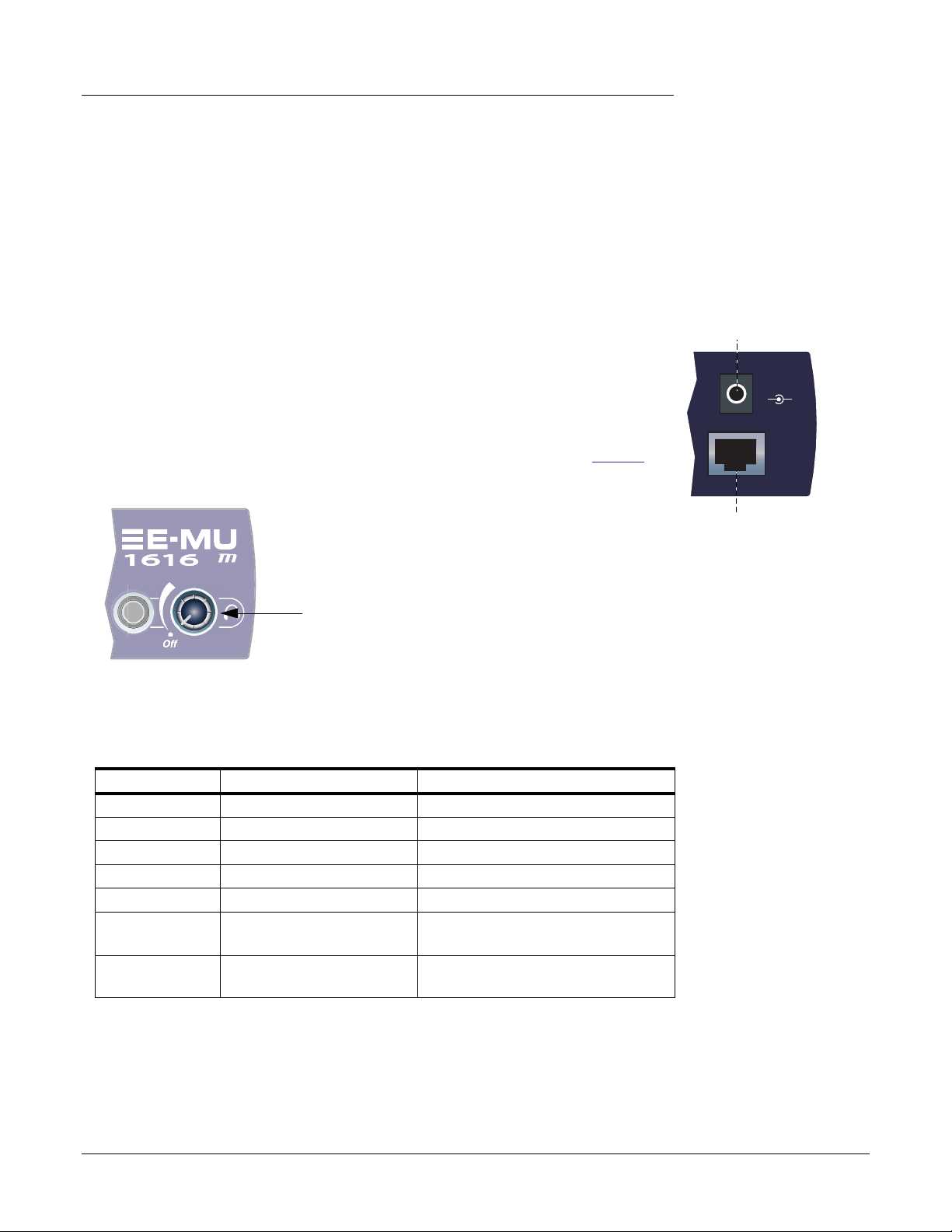
Connecting the MicroDock
Connect the supplied EDI cable between the 02 CardBus Card and the MicroDock.
1.
Connect the supplied +48 volt DC adapter to the+48VDC jack on the rear of the
2.
Microdock. See the diagram at right.
Connect your audio inputs and outputs to the MicroDock as shown on page 18.
3.
Turn the MicroDock on by turning the Headphone Volume control.
4.
2 — Installation
Connecting the MicroDock
+48V DC Adapter
VDC
48
+
EDI
—
The Headphone
Volume Control is
the Power Switch.
Connector Types
These connector types are used to connect the E-MU MicroDock hardware components.
They will be referred to by the name shown in the first column of the following chart:
Name
EDI CAT5 Connector 02 CardBus card and MicroDock
S/PDIF In RCA Connector S/PDIF digital audio devices
S/PDIF Out RCA Connector S/PDIF digital audio devices
ADAT Optical In TOSLINK Optical Connector ADAT digital audio devices (or S/PDIF)
ADAT Optical Out TOSLINK Optical Connector ADAT digital audio devices (or S/PDIF)
Mic/Line Inputs XLR Jacks or 1/4” jacks
Line In/Out 1/4” connectors Connect to balanced or unbalanced
Description Connects
XLR: connect to microphone
(balanced or unbalanced)
1/4”: instrument inputs or line inputs
inputs and outputs.
02 CardBus Card
Warning: The E-MU 02 CardBus card has been designed to use readily available
and inexpensive standard computer system cables. This makes it easy for you to find
replacement cables if your original cable becomes damaged or lost. However, because
these standard cables types are used for other purposes, you must use caution to avoid
connecting the cables incorrectly. DO NOT connect the supplied EDI cable to the
Ethernet or network connector on your computer. Doing so may result in permanent
damage to either your computer, the E-MU 02 CardBus card, or the MicroDock.
E-MU 1616/1616M CardBus Digital Audio System 11

2 — Installation
Connecting the MicroDock
12 Creative Professional
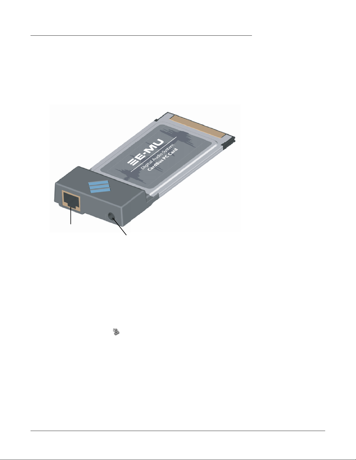
3 — CardBus Card & MicroDock
The E-MU 02 CardBus Card
The E-MU 02 CardBus card is the heart of the system and contains E-MU’s powerful
E-DSP chip. The powerful hardware DSP on this little card leaves more CPU power free
on your computer for additional software plug-ins and other tasks.
CardBus Connector
E-MU 02 CardBus Card
Connect to Computer
3 — CardBus Card & MicroDock
The E-MU 02 CardBus Card
Digital Audio System
EDI Connector
Connect to MicroDock
Monitor Output
Line Level or Headphones
Connections
CardBus Connector
Connects the E-MU 02 CardBus card to your computer.
Removing the CardBus Card
Before removing the CardBus card, you need to select “Safely Remove Hardware” from
the Taskbar. Otherwise ASIO channels will remain allocated to the Digital Audio System
and your other audio applications may develop problems or hang.
1.
From the Taskbar, select the icon. The “Safely Remove Hardware” pop-up
window appears.
Choose OK , then press the Eject button on the CardBus slot to eject the card.
2.
EDI Connector
Connects to the MicroDock using the supplied EDI cable. This cable provides a two-way
data link between the E-MU 02 and the MicroDock.
Monitor Output
This output is designed to drive stereo headphones or any line-level input. Adjust the
monitor output level in the PatchMix DSP application to control the volume of this
output.
E-MU 1616/1616M CardBus Digital Audio System 13
3 — CardBus Card & MicroDock
The MicroDock
The MicroDock
The MicroDock connects to the E-MU 02 CardBus card via the EDI cable.
The MicroDock provides (4) balanced analog inputs, (2) microphone preamp inputs,
(6) balanced line-level analog outputs, (3) stereo 1/8” outputs for connecting powered
computer speakers, (2) MIDI inputs, (2) MIDI outputs, a stereo headphone output, and
a RIAA equalized turntable preamp section which is “normalled” into line input 2L and
2R, 8 channels of ADAT digital input/output, and stereo S/PDIF digital input/output.
The MicroDock is
f
completely “hot
pluggable”— It’s OK to
plug or unplug the
MicroDock while the
computer is turned on.
Out
Line
A
In
1L
Mic
Clip
SL
-15
Line —
0
Mic —
1L
1R
1R
Line
B
-3
-6
-12
-20
+50
+65
2L
2L
Mic
Clip
-3
-6
SL
-12
-20
-15
0
Phono
2R
2R
2L
3L
48V
+50
+65
2R
Gnd
3R
S/PDIF
In
MIDI Cable
Out
2
1
The inputs are configured as follows:
mono microphone/line inputs (2 inputs)
(2)
(2) stereo pairs of line level inputs (4 inputs)
(1) stereo pair of S/PDIF/AES digital inputs (2 inputs)
(4) stereo pairs of ADAT channels on the ADAT optical input (8 inputs)
Out
It’s a good idea to
mute MicroDock inputs 2
in the PatchMix DSP
Off
mixer when nothing is
plugged in, since the
turntable preamp has a
very high gain (60dB)
and could contribute
48
VDC
+
—
3
EDI
extra noise to your mix/
monitor bus.
(1) RIAA equalized turntable preamp input allows you to connect a turntable without using
an expensive external preamp.
Note: These inputs are automatically disconnected
when plugs are inserted into inputs 2L & 2R.
MIDI input ports using the supplied breakout cable
(2)
The outputs are configured as:
(3) stereo pairs of line level outputs
(1) stereo pair driving a stereo headphone jack
(1)
stereo pair of S/PDIF/AES digital outputs
(4) stereo pairs of ADAT channels on the ADAT optical output
(3) stereo 1/8” computer speaker outputs. These outputs carry the same signals as the 3
stereo line level outputs and are provided as a convenience for connecting computer or
powered speaker systems.
(2) MIDI output ports using the supplied breakout cable
14 Creative Professional
(Share the same routing as Line Outs 1L/1R)
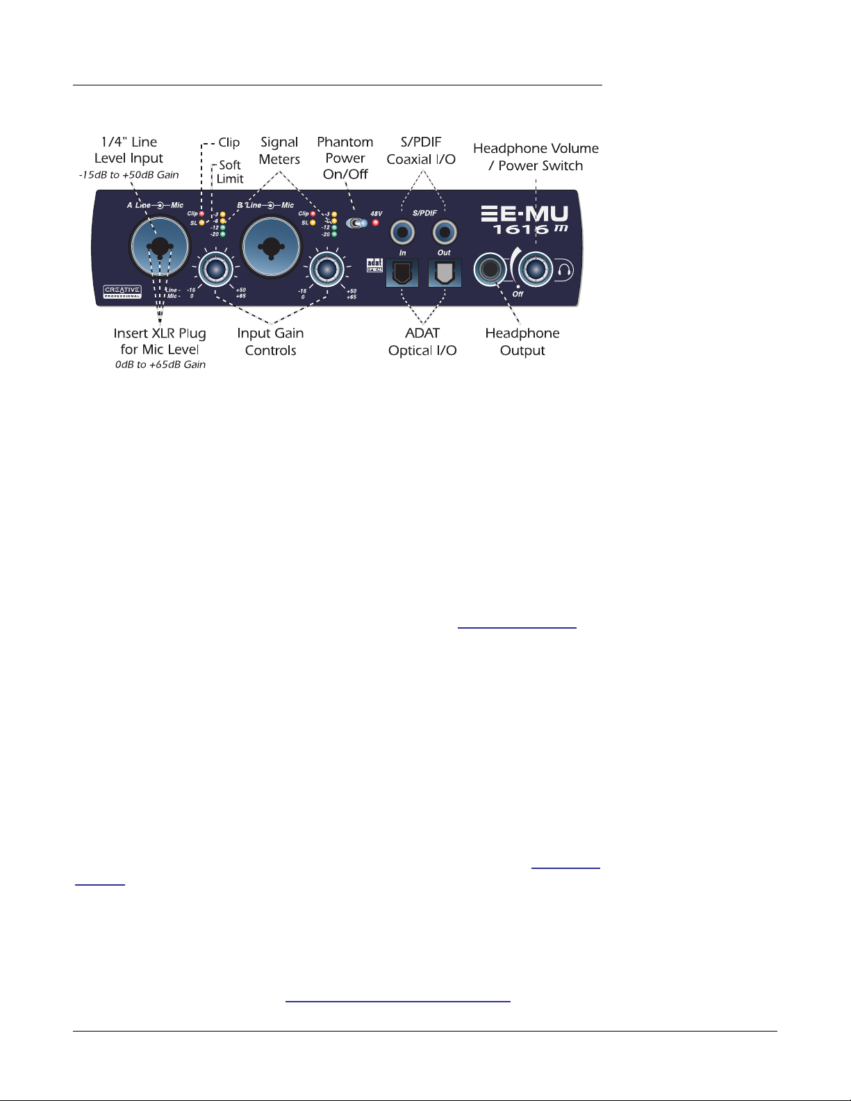
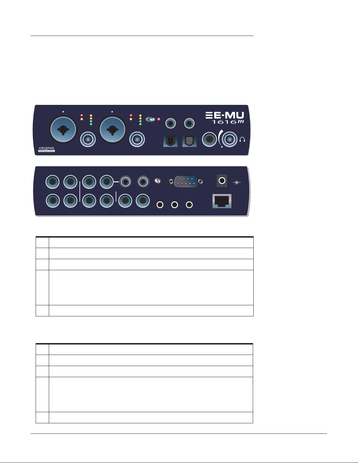
Front Panel Connections
Preamp Section
The front panel mono Mic/Line inputs A & B can be used as balanced microphone
inputs, hi-Z guitar pickup inputs, or line level inputs. The Neutrik combination jack
accepts microphones using a standard XLR connector or line level/hi-Z inputs (such as
an electric guitar) using a standard 1/4 inch TRS/TS connector.
Each preamp has a level control which sets the preamp gain from 0dB to +65dB for the
XLR input and from -15dB to +50dB for the Hi-Z line input. The line markings around
the knobs are calibrated in 10dB increments. The heavy hash marks on the gain controls
indicate unity analog gain to the converter inputs (~5dBV input = 0dBFS output).
A phantom power switch enables +48 volt phantom power supplied to both microphones. A red LED illuminates to indicate phantom power is enabled. The audio mutes
for a second when phantom power is turned on. After turning phantom power off, wait
two full minutes before recording to allow the DC bias to drain. See Phantom Power for
additional information.
Each microphone input has its own input level meters and clipping indicators. The LED
meters indicate signal presence. Adjust the input gain so that the yellow LEDs are illuminated. The red Clip LED indicates that the gain is set too high and the signal is clipping
the input. These LEDs monitor the signal directly at the analog-to-digital converters and
before any processing by the rest of the system. When setting the levels for signals being
sent into the MicroDock, the red clip indicator should never flash.
3 — CardBus Card & MicroDock
The MicroDock
Phantom Power
Caution:
microphones (notably
ribbon types) cannot
tolerate phantom power
and may be damaged.
Check the specifications
and requirements of
your microphone before
using phantom power.
Some
S/PDIF Digital Audio Input & Output
RCA phono jacks are standard connectors used for coaxial S/PDIF (Sony/Philips Digital
InterFace) connections. Each jack carries two channels of digital audio. The MicroDock
sends or receives digital audio data at 44.1k , 48k, 88.2k, 96k, 176.4k or 192k sample
rates. Data is always transmitted at 24-bits, but lower word widths can be read. The word
clock contained in the input data stream can be used as a word clock source. See System
Settings.
S/PDIF digital I/O can be used for the reception and/ or transmission of digital data
from external digital devices such as a DAT external analog-to-digital converter or an
external signal processor equipped with digital inputs and outputs.
The S/PDIF out can be configured in either Professional or Consumer mode in the
Session Settings menu. The MicroDock can also send and receive AES/EBU digital audio
through the use of a cable adapter. See Cables — balanced or unbalanced? for details.
E-MU 1616/1616M CardBus Digital Audio System 15
3 — CardBus Card & MicroDock
The MicroDock
ADAT Optical Digital Input & Output
The ADAT optical connectors transmit and receive 8 channels of 24-bit audio using the
ADAT type 1 & 2 formats. The word clock contained in the input data stream can be
used as a word clock source. See System Settings. Optical connections have certain
advantages such as immunity to electrical interference and ground loops. Make sure to
use high quality glass fiber light pipes for connections longer than 1.5 meters.
At the 88.2k, 96k, 176.4k or 192k sample rates, the industry standard S/MUX interleaving scheme is used for ADAT input and output. S/MUX uses additional ADAT
channels to gain additional bandwidth on the existing interface. See the chart below or
go here for additional information.
Important:
using any type of digital
I/O such as S/PDIF or
ADAT, you MUST sample
sync the two devices or
clicks and pops in the
audio will result.
When
Sample Rate
44kHz/48kHz
88kHz or 96kHz 4 channels of 24-bit audio, using S/MUX standard interleaving
176kHz or 192kHz 2 channels of 24-bit audio, using S/MUX standard interleaving
Number of Audio Channels
8 channels of 24-bit audio
The ADAT intputs and outputs can be configured in the System Settings (page 25) to
send and receive S./PDIF optical data at 44.1k , 48k, 88.2k, or 96k sample rates.
S/PDIF Optical is not supported at 176.4k or 196k due to the bandwidth limitations of
the optical components.
Headphone Output & Volume Control
The headphone output drives standard stereo headphones and the adjacent volume
control sets the listening level. The headphone amplifier can drive headphones with
impedance as low as 24 ohms. The headphone output uses a high-current version of
thehigh-quality output amplifiers used on the other channels. For this reason it has a
very clean signal that can be used as another stereo output if you need it.
Note:
E
does not support AC3
passthrough at this time.
PatchMix DSP
16 Creative Professional
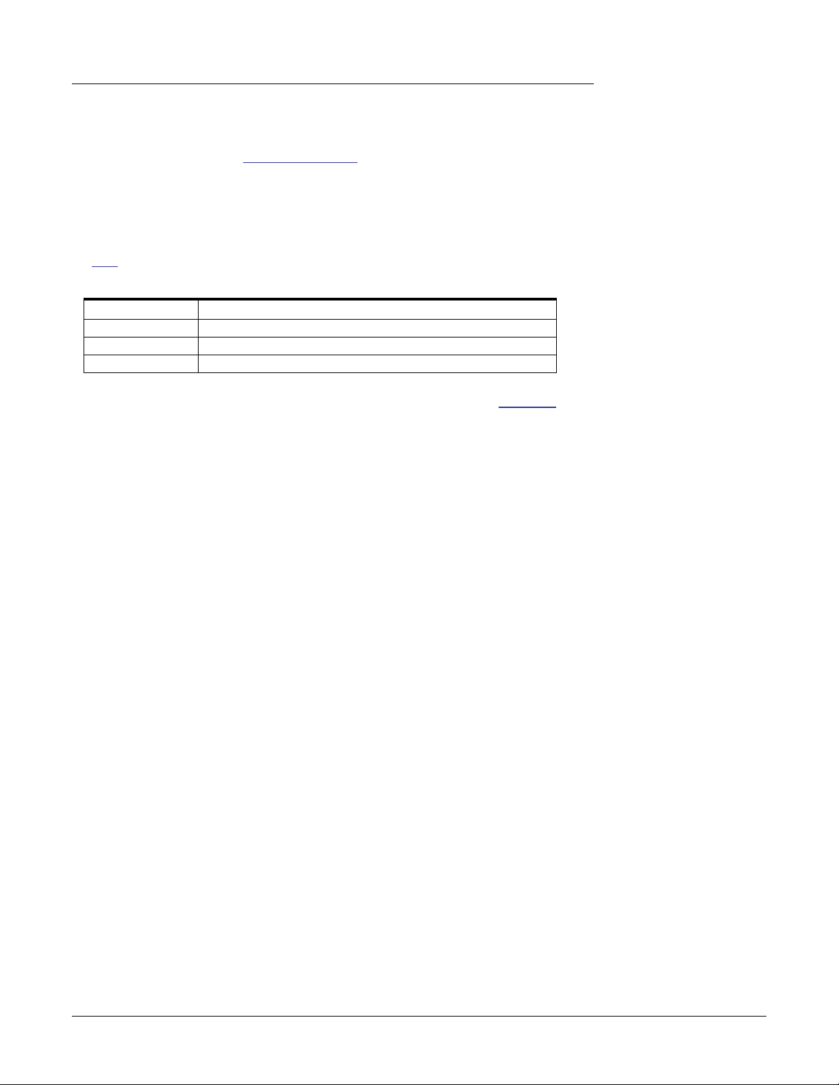
Front Panel
Analog Connections
Use the 3-pin XLR jack
for Low Impedance
microphones.
3 — CardBus Card & MicroDock
The MicroDock
Mic
Line
Line —
Mic —
Mic
Clip
-3
-6
SL
-12
-20
-15
0
A
Use the center
Phone Jack for
High Impedance
Instrument
instruments such
as electric guitar
or bass.
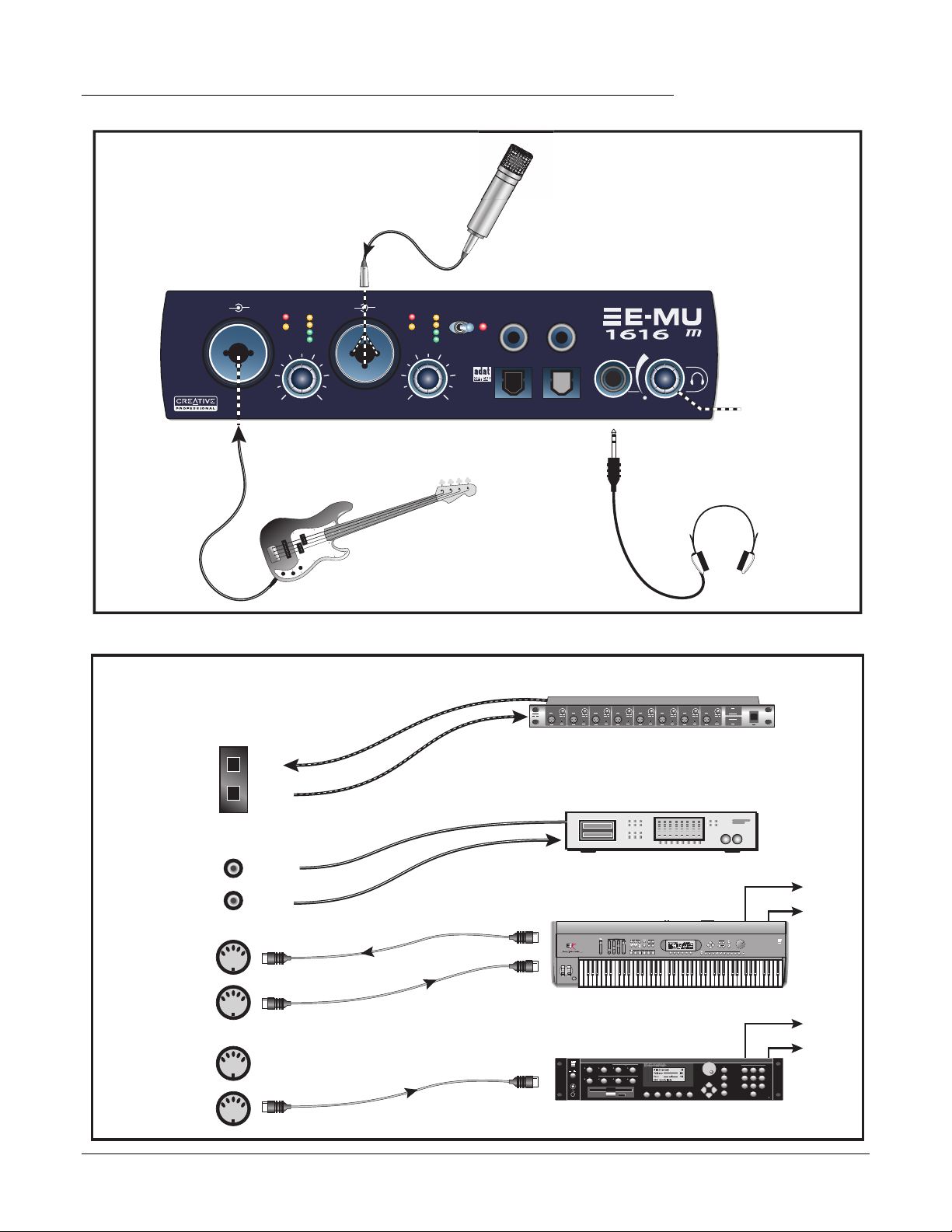
Digital Connections
ADAT
(Optical)
In
Out
Line
B
+50
+65
Mic
Clip
-3
-6
SL
-12
-20
-15
0
+50
+65
48V
In
S/PDIF
Out
Off
On/Off
& Phone Volume
Stereo
Headphones
External A/D — D/A Converter
Out
Optical
1 2 3 4 5 6 7 8
In
(8 more analog inputs & outputs)
DAT or CD
Digital Audio Device with S/PDIF
Out
In
MIDI Keyboard
REAL TIME CONTROLLERS
ASSIGNABLE KEYS
SEQUENCER
Audio Outs
PRESET
SAMPLE
LEVEL
EXIT
ENTER
PAGE
PRESET SELECT
RETURN
EMULATOR
0.987654321
S/PDIF
(Coax)
In
MIDI 1
In
Out
Coaxial
MIDI Out
MIDI In
Out
INC/YES
DEC/NO
ENTER
ESCAPE
Audio Outs
TRIGGERS
ABC
DEF
123
JKL
MNO
GHI
456
TUV
WXY
PRS
789
QZ
0
MIDI
MIDI Sound Module
In
MIDI 2
Out
MIDI In
I
O
VOLUME
E-MU 1616/1616M CardBus Digital Audio System 17
MASTER/GLOBAL
TRANSPOSE DIGITAL PROCESSINGSAMPLE MANAGEMENT
MULTIMODE
PRESET MANAGEMENT DYNAMIC PROCESINGPRESET DEFINITION
SAMPLE
PRESET
DRIVE SELECT LOAD SAVE AUDITION TRIGGER MODE
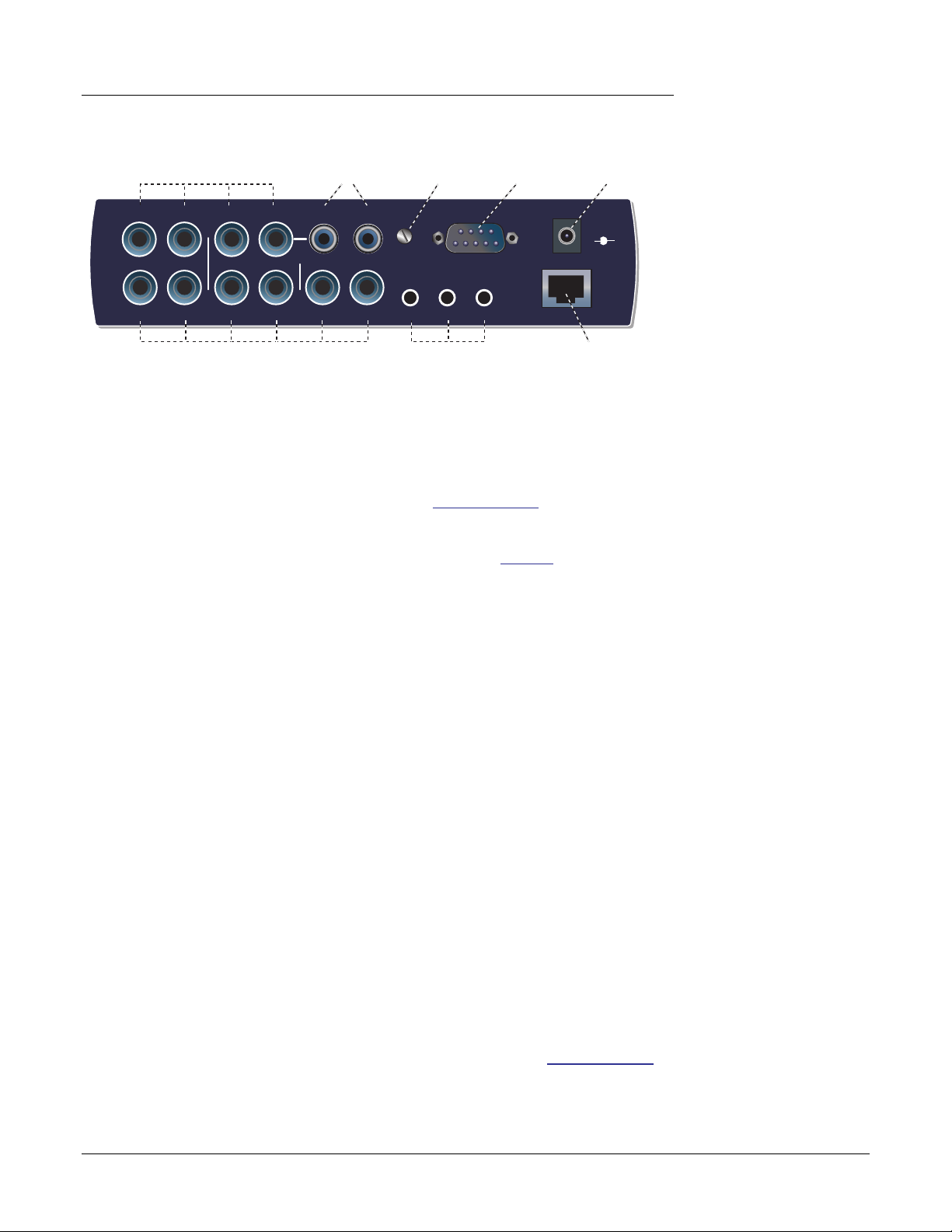
3 — CardBus Card & MicroDock
The MicroDock
Rear Panel Connections
4 Balanced Line Level Inputs
(configured as 2 stereo pairs)
1L
1R
In
Out
1L
1R
(configured as 3 stereo pairs)
Turntable Inputs
(tied to line input 2)
Phono
2L
2R
2L
2L
2R
2R
3R
3L
Turntable
Ground
Gnd
Out
2
1
Alternate Outputs6 Balanced Line Level Outputs
(same as outputs 1-3)
MIDI Cable
MIDI Port
Connector
3
48 Volt DC
Power Input
48
VDC
+
—
EDI
Connect to
E-MU 02 CardBus Card
Line Level Analog Inputs
4 balanced 24-bit, line-level, analog inputs are provided (1-2). These can be used to
input any line level signal from keyboards, CD-players, cassette decks, etc. The analog
inputs are assigned to mixer strips in the mixer application. The line level inputs can be
set to accommodate the consumer -10dBV standard, or the pro audio +4 dBu standard
in the I/O screen of the Session Settings dialog box. See I/O Settings.
The maximum input level is 18dBV (=20.2dBu).
Either TRS balanced or TS unbalanced cables can be used. See page 84 for additional
information about unbalanced cables and connectors. The line-level inputs are all
servo-balanced, enabling them to convert unbalanced signals to balanced signals
internally to reduce noise.
Turntable Inputs & Ground Lug
The RCA turntable inputs feed an RIAA equalized preamp designed for moving magnet
type phono cartridges with 60 dB of gain. Connect the ground lead from your turntable
to the ground lug to prevent hum.
The turntable inputs share line level inputs 2L and 2R. Inserting a plug into Line Input 2
disconnects the turntable preamp from that channel. Do NOT leave your turntable
connected when using inputs 2L and 2R, since this can cause a ground loop.
Important: Do NOT plug in line level signals to the turntable inputs. The turntable
inputs are designed to accept the extremely low-level signal from a phonograph
cartridge. Use RCA to 1/4” adapters to connect line level signals to the line level analog
inputs.
Line Level Analog Outputs
Six balanced 24-bit, line-level, analog outputs are provided (1-3). Output pair 1 is designated as the Monitor Output and is fed by the monitor bus of the PatchMix DSP mixer
application. We suggest that you plug your speakers in here. Special anti-pop circuitry
mutes the analog outputs when power is turned on or off.
Like the analog line inputs, either TRS balanced or TS unbalanced cables can be used.
Balanced cables provide better noise immunity and +6dB higher signal level. The output
line level can be set to accommodate the consumer -10dBV standard, or the pro audio
+4 dBu standard in the I/O screen of the Session Settings dialog box. See I/O Settings.
The maximum input and output line levels are matched when the input and output
settings are set to the same mode (pro or consumer) in the I/O preferences screen.
It’s also a good idea
to mute the Dock In strip
2L/2R in the PatchMix
DSP mixer when nothing
is plugged in, since the
turntable preamp has a
very high gain (60dB)
and could contribute
extra noise to your mix/
monitor bus.
Balanced Cables:
You should ONLY use
balanced (TRS) cables if
BOTH pieces of
equipment use balanced
connections. Connecting
balanced cables between
balanced outputs and
unbalanced inputs can
actually increase noise
and introduce hum.
18 Creative Professional
Computer Speaker Analog Outputs
These stereo mini-phone (3.5mm) jacks duplicate line level outputs 1-3 with a lower
output level to accommodate consumer speakers. These line level outputs are designed
to interface easily with powered speakers.
Computer Speaker Output Duplicates Line Level Output
1 L/R Tip = 1L Ring = 1R
2 L/R Tip = 2L Ring = 2R
3 L/R Tip = 3L Ring = 3R
MIDI 1 & 2 In/Outs
MIDI input and output ports allow you to interface any type of MIDI equipment such as
keyboards, effect units, drum or guitar controllers (anything with MIDI). The MIDI
drivers were installed when you installed your PatchMix DSP software and the MIDI
ports will appear in your system control panel under “Sounds and Audio Devices”.
There are two completely independent sets of MIDI input and output ports on the
MicroDock, which can be assigned in your specific MIDI applications.
Connect the MIDI breakout cable to the D-connector on the MicroDock. Connect MIDI
Out to the MIDI In port of your synthesizer and MIDI Out of your synth to MIDI In of
the MicroDock MIDI cable.
3 — CardBus Card & MicroDock
The MicroDock
EDI Connector (Card)
Connects the MicroDock to the E-MU 02 CardBus card using a CAT5-type computer
cable. The cable supplied with the MicroDock is specially shielded to prevent unwanted
RF emissions.
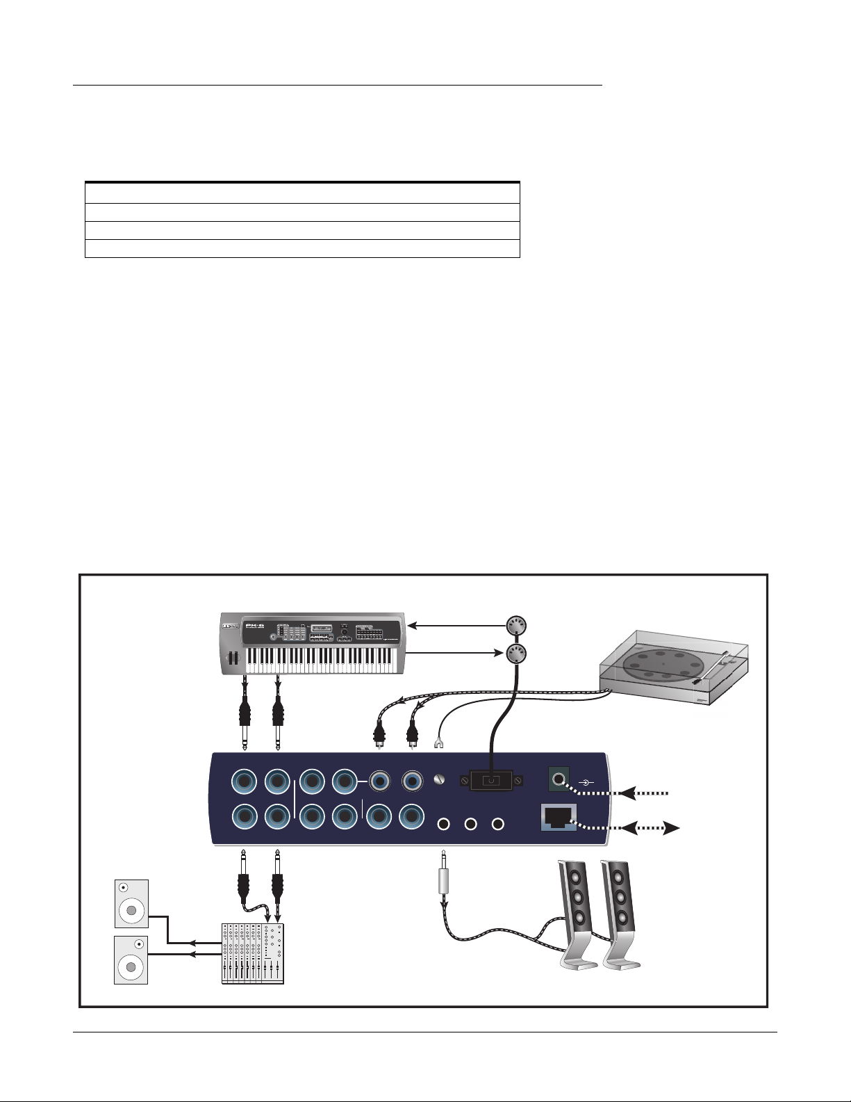
Basic
Connections
Audio
from
Synthesizer
In
Out
Audio
to
Monitors
MIDI Synthesizer
1L
1R
1L
1R
Mixer
Speakers
**
2R
2L
2L
2R
&
MIDI In
Out
MIDI 1
MIDI Out
Phono
2L
2R
Gnd
3R
3L
MIDI Cable
Out
2
1
In
48
VDC
+
3
EDI
Connect
Desktop
Speakers to
1/8″ jacks
e
r
o
e
t
S
Turn
—
AC Adapter
CardBus
Card
Powered
Desktop
Speakers
* Note: Line Inputs 2L/2R and Phono 2L/2R cannot be used at the same time.
E-MU 1616/1616M CardBus Digital Audio System 19
3 — CardBus Card & MicroDock
The MicroDock
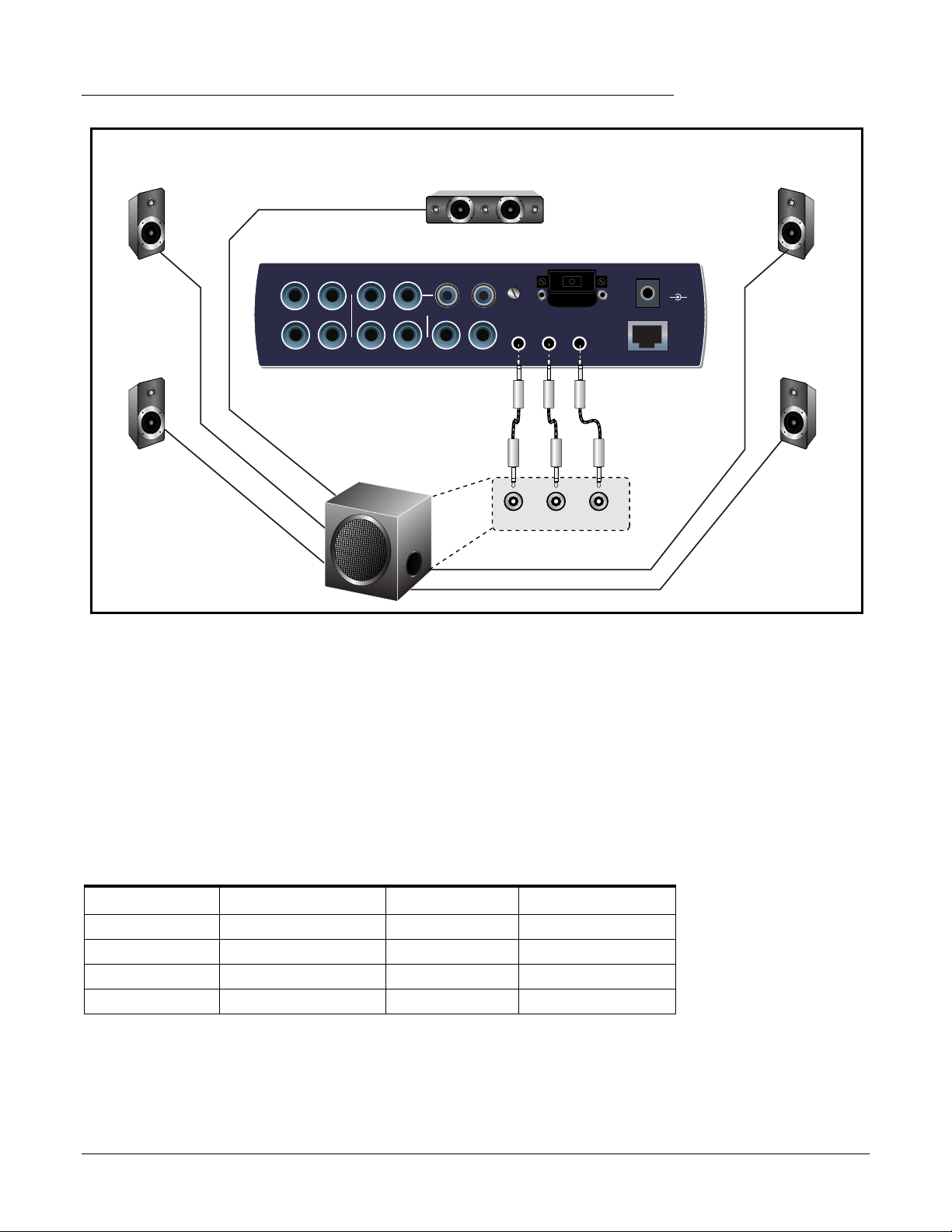
5.1 Surround Speaker Connections
Center
Left
Front
Phono
2L
2R
1L
In
Out
1L
2L
1R
1R
2L
2R
2R
Gnd
3R
3L
MIDI Cable
Out
2
1
3
Left
Rear
Front Rear Ctr/Sub
Sub-Woofer
(with built-in power amps)
The 1/8” stereo jacks make it easy to connect to powered surround sound speakers.
Only three stereo cables are necessary with many speaker systems (see above). The 1/8”
jacks duplicate the 1/4” outputs.
48
VDC
+
—
EDI
Right
Front
Right
Rear
You can connect the 1/8” stereo jacks to your surround speakers and connect the 1/4”
outputs to your other gear for music creation. When you want to monitor in surround,
simply open the 5.1 Session and turn on your surround speakers.
The chart below shows how to connect the outputs for 5.1 surround sound playback.
Multichannel WAVE to Surround Sound Speaker Channels
(using the factory 5.1 DVD Playback Session)
WAVE Strip Surround Channels 1/4” Outputs 1/8” Outputs
E-DSP WAVE 1/2 Front Left / Front Right 1L = FL 1R = FR 1 (Tip = FL Ring = FR)
E-DSP WAVE 3/4 Center / Subwoofer 3L = C 3R = Sub 3 (Tip = C Ring = Sub)
E-DSP WAVE 5/6 Rear Left / Rear Right 2L = RL 2R = RR 2 (Tip = RL Ring = RR)
E-DSP WAVE 7/8 Side Left / Side Right N/A N/A
20 Creative Professional
4 — The PatchMix DSP Mixer
PatchMix DSP
The PatchMix DSP Mixer is a virtual console which performs all of the functions of a
typical hardware mixer and a multi-point patch bay. With PatchMix, you may not even
need a hardware mixer. PatchMix DSP performs many audio operations such as ASIO/
WAVE routing, volume control, stereo panning, equalization, effect processing, effect
send/return routing, main mix and monitor control and allows you to store and recall
these “Sessions” at will.
To Invoke the PatchMix DSP Mixer
1.
Left-click once on the E-MU icon on the Windows System Tray. The PatchMix
DSP mixer window appears.
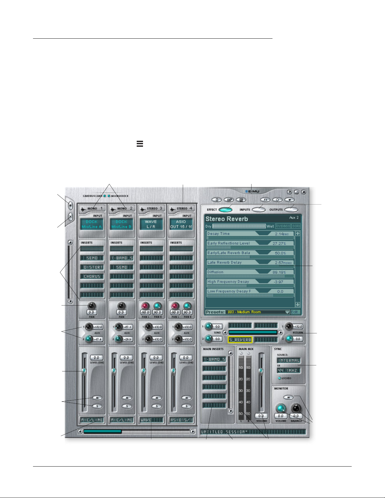
Overview of the Mixer
Add New
Strip
Physical Input Strips
ASIO Input Strip
Toolbar
4 — The PatchMix DSP Mixer
PatchMix DSP
f Click on the buttons
and knobs in the mixer
screen below to jump to
the description of the
control.
Display
Select
Buttons
Delete
Strip
Channel
Insert
Section
Pan
Controls
Aux
Sends
Volume
Fader
Solo/Mute
Buttons
“TV”
Screen
Aux
Effects
Section
Sync/
Sample
Rate
Indicators
Monitor
User
Definable
Scribble Strip
E-MU 1616/1616M CardBus Digital Audio System 21
Controls Windows Source Audio
(Direct Sound, Windows Media, etc.)
WAVE Strip
Main
Inserts
Current
Session
Name
Main Mix
Output Volume
& Meters
Volume/Balance
/Mute Controls
4 — The PatchMix DSP Mixer
Overview of the Mixer
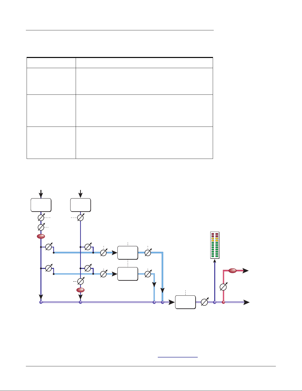
Mixer Window
The Mixer consists of four main sections.
Application Toolbar Lets you manage sessions and show/hide the various views.
Main Section Controls all the main levels, aux buses, and their inserts. This section
also has a “TV” which shows parameters for the currently selected
effect and the input/output patching. It also shows the session’s
current sample rate and whether it’s set to internal or external clock.
Mixer Strips This section is located to the left of the Main Section and shows all
the currently instantiated mixer strips. Mixer strips can represent
Physical analog/digital inputs, or Host inputs such as ASIO or
Direct Sound. Mixer strips can be added or deleted as necessary.
This section can be resized by dragging the left edge of the frame.
Effects Palette This popup window is invoked by pressing the FX button in the
toolbar. Iconic representations of all effects presets are shown here,
organized by category. From this window, you can drag and drop
effect presets into the insert slots available on the mixer strips and
main section aux buses and main inserts.
A simplified diagram of the mixer is shown below.
Input
Post-Fader Strip
Insert
Section
Panning
Input
Pre-Fader Strip
Insert
Section
Fader
MUTE
Aux 1
Aux
Bus 1
Aux 1
Send
Amount
Aux
Effects
Insert
Section
Aux 2
Aux
Bus 2
Aux 2
Send
Amount
Insert
Section
Fader
MUTE
Main Bus
Return
Amount
Return
Amount
Mixer Block Diagram
Meter
Main Bus
Effects
Insert
Section
Main
Level
Monitor
Out
MUTE
Monitor
Level
Main
Out
Output 1L/1R
& Headphones
Pre Fader or Post Fader
When creating a new Mixer Strip, you have the option for the Aux Sends to be placed
Post Fader (both Aux Sends come after the channel fader) or Pre Fader (both Aux Sends
come before the channel fader). The Pre-fader option allows you to use either Aux Send
as another mix bus, which is unaffected by the channel fader. More Information.
22 Creative Professional
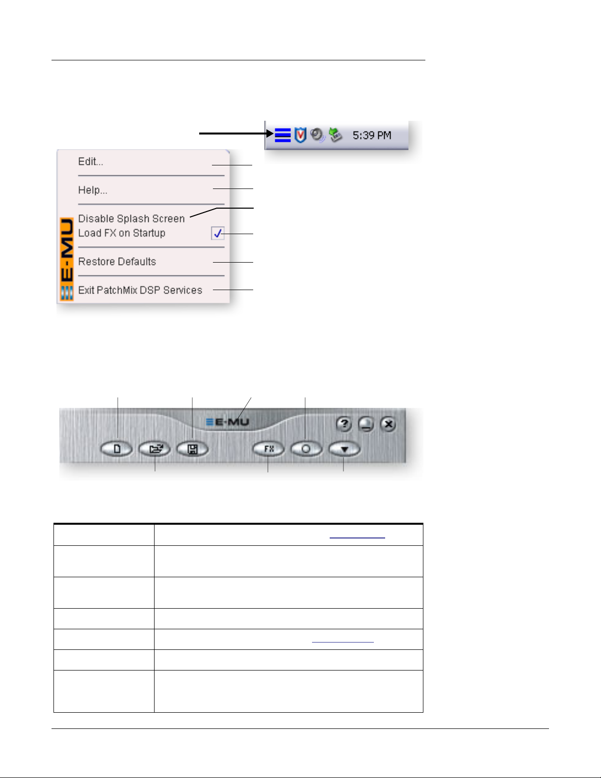
E-MU Icon in the Windows Taskbar
Right-clicking on the E-MU icon in the Windows taskbar calls the following window.
Right-Click Here
Opens the PatchMix DSP Mixer.
Calls the PatchMix DSP help system.
Disables the splash screen that appears at
boot-up.
When unchecked, FX are not loaded until
needed, resulting in faster computer boot.
Restores the default PatchMix DSP and
driver settings.
Closes the PatchMix DSP background
program, disabling use of all audio I/O
from the E-MU hardware. Open the PatchMix DSP application to start audio again.
4 — The PatchMix DSP Mixer
E-MU Icon in the Windows Taskbar
f Restore Defaults:
Always try this option first
if PatchMix is crashing or if
you are having any other
strange audio problems.
The Toolbar
New
Session
Open
Session
New Session
Open Session Calls up the standard “Open” dialog box, allowing you to open a
Save Session Calls up the standard “Save” or “Save As…” dialog boxes, allowing
Show/Hide Effects Toggle button that shows or hides the FX palette.
Session Settings Calls up the Sessions Settings window. Session Settings.
Save
Session
“About”
PatchMix DSP
Show/Hide
Effects
Session
Settings
Global
Prefs
Calls up the “New Session” dialog box. New Session.
saved Session.
you to save the current Session.
f Click the buttons in
the toolbar to learn about
their function.
Global Preferences Calls up the Global Preferences window.
About PatchMix DSP Right-Click on the E-MU logo to view the “About PatchMix DSP”
screen, which provides the software and firmware version
numbers and other information.
E-MU 1616/1616M CardBus Digital Audio System 23
4 — The PatchMix DSP Mixer
The Session
The Session
The current state of the PatchMix DSP mixer (fader settings, effects routings…everything!) can be saved as a Session. Whenever you create or modify a mixer setup, all you
have to do is Save it to be able to recall it at a later time.
Before you begin using PatchMix DSP, you need to set it up to be compatible with the
other software applications you may be running. The most important consideration is
your system sample rate. PatchMix DSP and any applications or other digital gear you
are using must be set to the same sample rate. PatchMix DSP can run at 44.1kHz,
48kHz, 88kHz, 96kHz, 176.4 kHz or 192kHz, but its complete set of features are only
available at 44.1kHz or 48kHz. See Chapter 6 — Using High Sample Rates for details.
Once the sample rate is set, you can only easily switch between 44.1k and 48k. You
cannot switch between 44/48k and 88k/96k/176k/192k. With a change to these high
sample rates, you must start a new session.
You can also set up an external sync source, thereby obtaining the sample rate from
some other device or application. External sync can be obtained from the ADAT input or
S/PDIF input. If the session is set at 44.1kHz or 48kHz and the external source is
coming in at a higher rate (such as 96k), the Sync Indicator will be extinguished (off),
but PatchMix will attempt to receive the external data. The two units are NOT sample
locked however, and you should correct this condition to avoid intermittent clicks in the
audio. Always check for the presence of the LOCKED indicator whenever you are
using a digital interface.
PatchMix DSP comes with several session templates to choose from so when you create
a new session you can either create a “blank” session based around a designated sample
rate, or select from a list of template starting points.
In a PatchMix DSP session the number of strips in the mixer is dynamically configurable. This allows you to create only those strips you need up to a maximum number
determined by available DSP resources and available inputs.
Important: When
using any form of digital
input, you MUST
synchronize the Digital
Audio System to the
external digital device
(S/PDIF/ADAT).
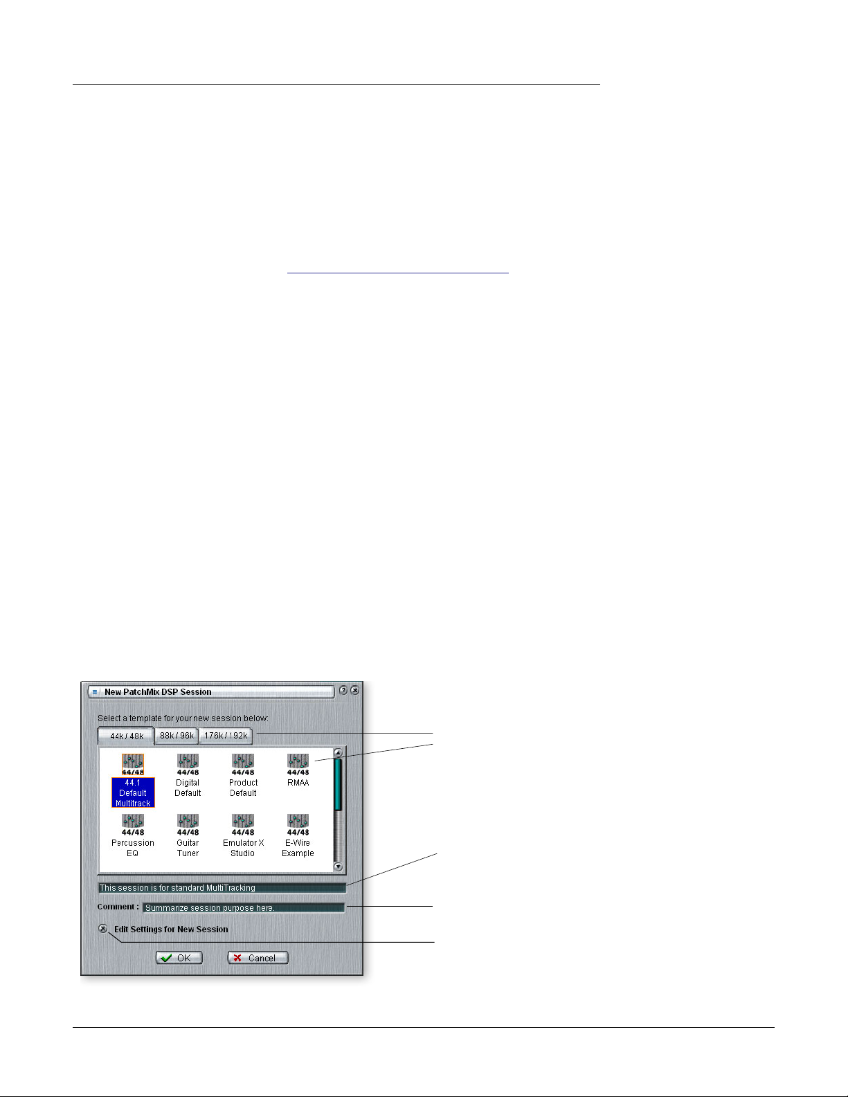
New Session
You create a new session by clicking the “New Session” button in the PatchMix DSP
main Toolbar. The following dialog box appears.
Select a Template or new
Session at the desired
sample rate
Session Description
Add your own comment
or note about the Session
Check this if you want to
edit the New Session.
24 Creative Professional
You can now select one of the factory template sessions. The factory templates are preprogrammed with specific setups such as audio recording or mixing. The selector tabs
categorize Template Sessions into three groups based on sample rate, 44.1k/48k, 88k/
96k, or 176k/192k.
You can create your own templates by simply copying or saving sessions into the
“Session Templates” folder (Program Files\Creative Professional\E-MU PatchMix
DSP\Session Templates).
There is also a Comment area that you can use to give yourself some clue as to what you
were thinking when you created the session.
Selecting a Session at 176.4kHZ or 192kHz
When operating at 176.4k or 192k sample rates, the number of I/O channels are
slightly reduced. At these high sample rates you must select one of three types of
sessions each contianing a different I/O configuration. Please see page
81 for details.
Open Session
To Open a saved session, click on the Open Session button. A dialog box appears
allowing you to choose one of your saved Sessions to open. Choose one of your saved
sessions and click on the Open button.
4 — The PatchMix DSP Mixer
The Session
Save Session
To Save a session, click on the Save Session button. A Save dialog box appears allowing
you to choose a location in which to save the current Session. The “My Sessions” folder
is chosen by default.
Get in the habit of saving the session whenever you have created a special mixer setup.
This will make your life much easier as you can recall a setup for many different audio
modes such as: recording, mixing, special ASIO routings, etc.
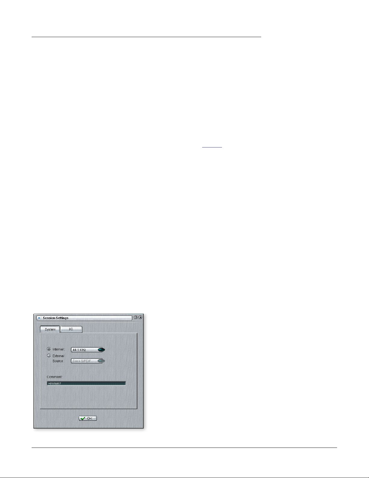
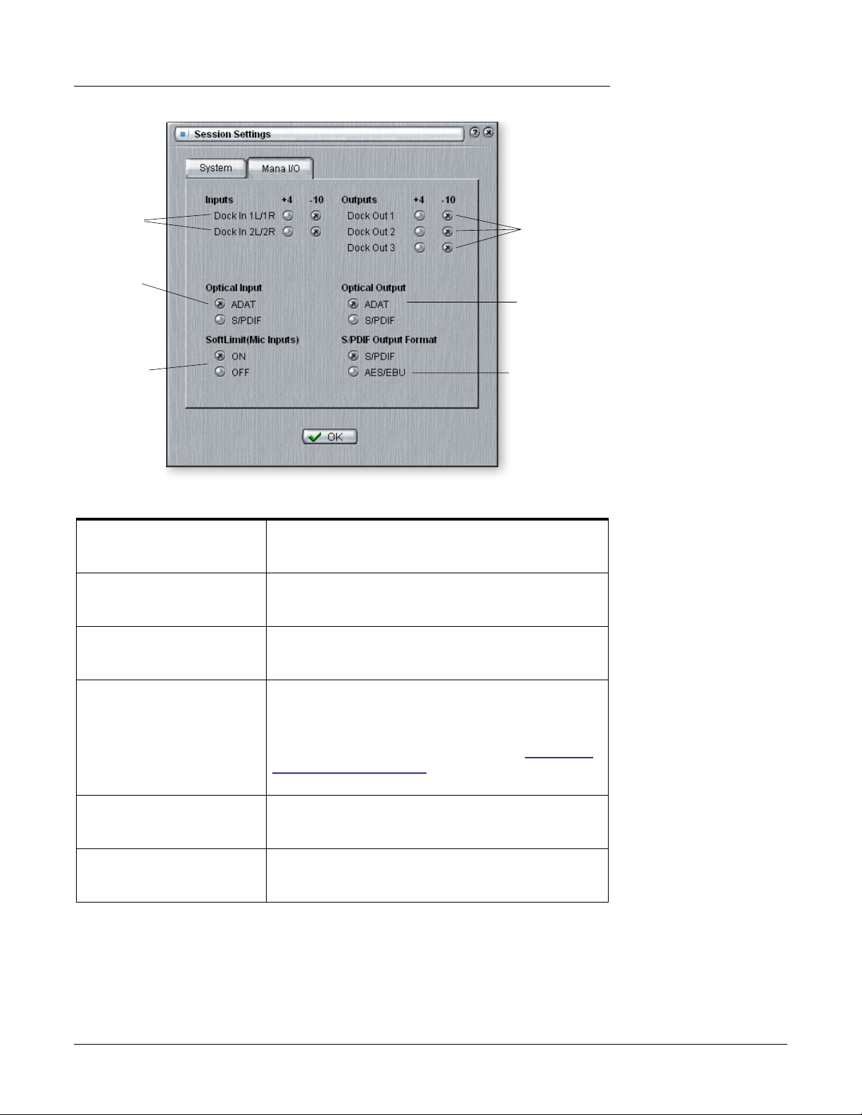
Session Settings
System Settings
Pressing the Session Settings button on the toolbar brings up the System Settings
window shown below. Click the tabs to select System or I/O options.
E-MU 1616/1616M CardBus Digital Audio System 25
4 — The PatchMix DSP Mixer
The Session
The System Settings include the following:
• Internal/External Clock Selects between internal or external word clock source
as the master clock source for the system
• Sample Rate Selects the sample rate when using internal clock.
Your choices are: 44.1kHz, 48kHz, 88.2kHz, 96kHz,
176.4kHz, 192kHz.
• External Clock Source
(ext. clock only)
Select from: ADAT, or S/PDIF as an external sample clock
source.
Using External Clock
Whenever you are using any digital I/O such as ADAT or S/PDIF, one of the digital
devices MUST supply the master clock to the others. This master clock runs at the system
sample rate and can be embedded into a data stream such as S/PDIF or ADAT.
Common symptoms of unsynced digital audio include, random clicks or pops in the
audio or failure of the digital stream to be recognized. Always check for the presence of
the “LOCKED” indicator whenever you are using a digital interface.
If an External Clock is interrupted or switched after the Session has been created (except
between 44.1k <-> 48k), the “LOCKED” indicator will be extinguished and PatchMix
will attempt to receive the external data. The two units are NOT sample locked however,
and you should correct this condition to avoid intermittent clicks in the audio.
I/O Settings
You can set the level (-10dBV or +4 dBu) for each pair of analog outputs and the input
gain setting for each pair of analog inputs.
An output setting of +4 provides the most output and is compatible with professional
audio gear. Balanced output cables provide a +6dB hotter signal than unbalanced cables
when used with balanced inputs. Do NOT use balanced cables unless your other gear
has balanced inputs. See “Cables — balanced or unbalanced?” in the Appendix for more
information.
E Note: if set to
“External” without an
external clock present,
PatchMix DSP defaults to
the internal 48kHz clock
rate.
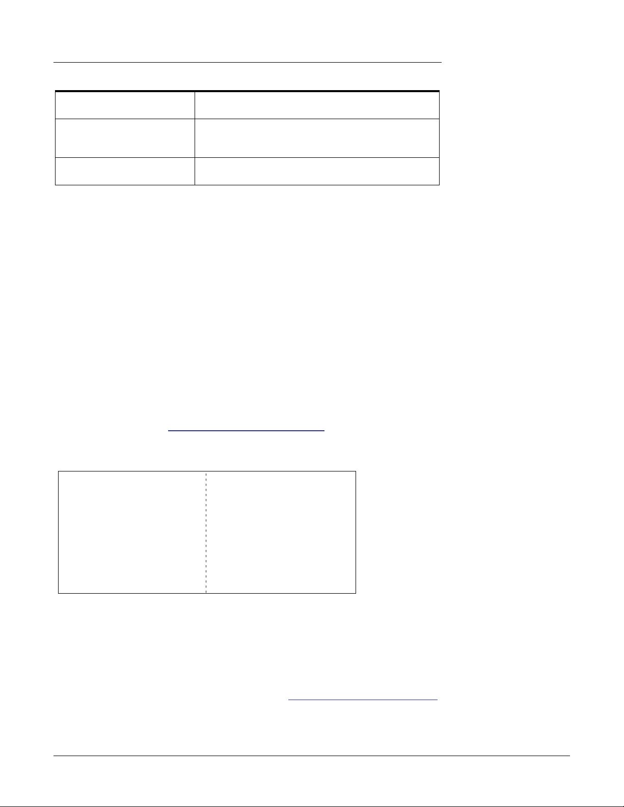
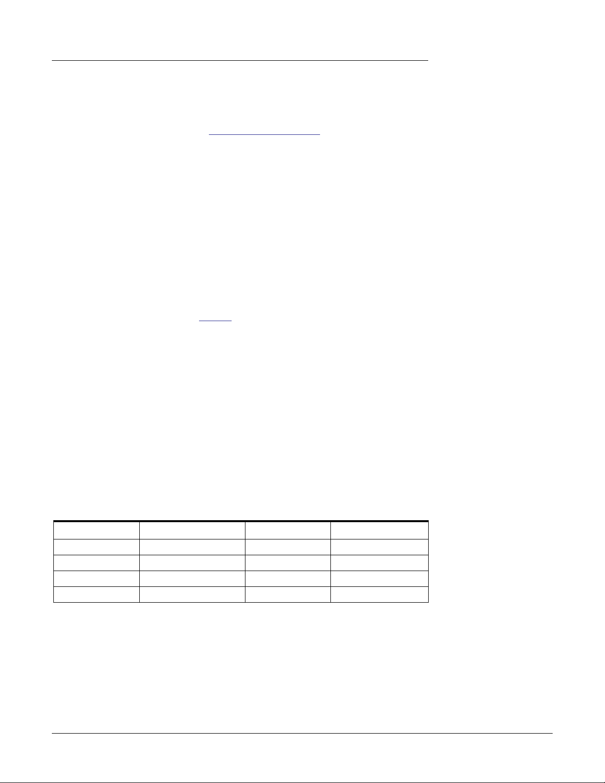
Comparison of -10dBV & +4dBu Signal Levels
Consumer
Clipping —>
Headroom
+ 6 dBV
+ 2 dBV
{
-10 dBV
0 dBV = 1V RMS 0dBu = .777V RMS
An input setting of -10 is compatible with consumer audio gear and works best with low
level signals. (-10dBV is approximately 12dB lower than +4dBu.) Choose the setting that
allows you to send or receive a full scale signal without clipping.
Setting correct input and output levels is important! You can measure the level of an
input by inserting a meter into the first effect location in the strip. Adjust your external
equipment outputs for the optimum signal level. See “To Set the Input Levels of a Strip”
for details.
Professional
(balanced)(unbalanced)
+20 dBu
=
+8 dBu
=
+4 dBu
=
-8 dBu
<— Clipping
Headroom
}
f Input too weak?
Use -10 Input setting.
Output too weak?
Use +4 Output setting
26 Creative Professional
4 — The PatchMix DSP Mixer
The Session
Input Level
Settings
Optical
Input
Select
Mic Soft
Limiting
On/Off
• Inputs +4 or -10 Selects between Consumer level (-10dBV) or
Professional level (+4dBu) inputs.
(Use the -10dBV setting if your input is too weak.)
• Outputs +4 or -10 Selects between Consumer level (-10dBV) or
Professional level (+4dBu) outputs.
(The +4 dBu setting outputs a hotter level.)
• Optical Input Select Selects between ADAT or optical S/PDIF for the MicroDock
ADAT Input. The coaxial S/PDIF input is disabled when
S/PDIF optical is selected.
• Microphone Input
Soft Limiting
• Optical Output Select Selects between ADAT or optical S/PDIF for the MicroDock
• S/PDIF Output Format Selects between S/PDIF or AES/EBU format for S/PDIF. This
The Mic/Hi-Z inputs have built-in “soft limiters” which
automatically turn down the gain before the signal
overloads the A/D converters. The soft limiters allow you to
record a hotter signal without fear of clipping.
This control turns the soft limiters On or Off. See
the Best Possible Recording for additional information
about the soft limiters.
ADAT Output. The coaxial S/PDIF Output is disabled when
S/PDIF optical is selected.
sets the S/PDIF-AES status bit, but does not affect the signal
level.
Output Level
Settings
Optical
Output
Select
S/PDIF
Output
Format
Making
E-MU 1616/1616M CardBus Digital Audio System 27
4 — The PatchMix DSP Mixer
f Physical input strips
are shown with BLUE text.
f Host input strips are
shown with WHITE text.
f The Input Type will
turn RED if the input is not
available. (The MicroDock
may be disconnected.)
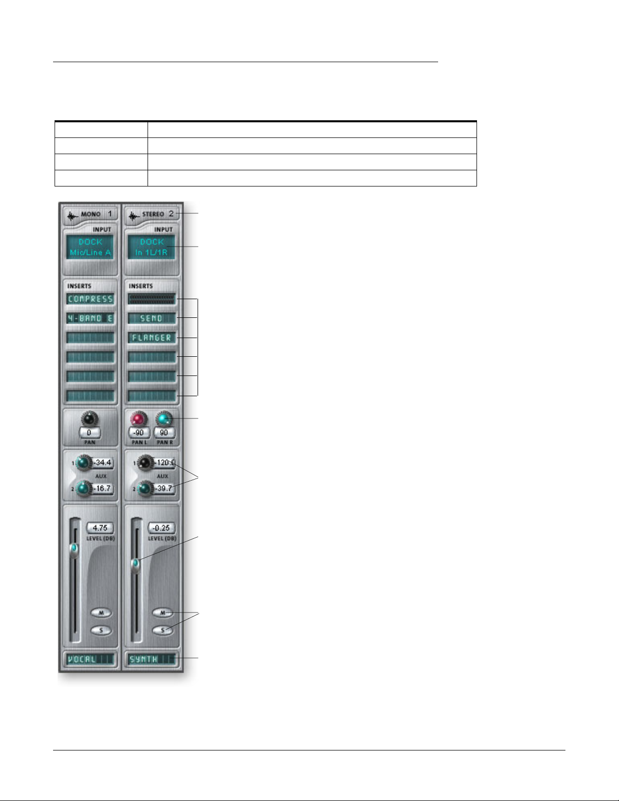
Input Mixer Strips
Input Mixer Strips
PatchMix DSP Input Mixer Strips are stereo except for the MicroDock Mic/Line inputs.
Each input mixer strip can be divided into four basic sections.
• Insert Section Effects, EQ, External/Host Sends & Returns can be inserted into the signal path.
• Pan Controls These controls position the signal in the stereo sound field.
• Aux Sends Used to send the signal to sidechain effects or to create separate mixes.
• Volume Control Controls the output level of the channel.
Mono/Stereo
Input Type
Insert Section
Pan Controls
Aux Sends
Channel
Volume
Control
Input Type
The very top of the strip is labeled
mono or stereo and displays the type
of the assigned input. Input mixer
strips can be added as desired and can
be configured to input the following:
• Physical input = Hardware
(Analog/SPDIF/ADAT).
• Host Input = Software
(Direct Sound, WAV, ASIO source)
Inserts
You can drag and drop effects from the
Effects Palette or Right-click to insert a
Physical or ASIO Send or Send/Return
A Peak Meter, Trim Control or Test
Signal can also be inserted by Rightclicking.
Pan Controls
These controls allow to you position
the channel in the stereo sound field.
Dual controls on stereo strips allow
you to position each side independently.
Aux Sends
These controls send the signal to
sidechain effect processors such as
reverb and delay. They can also be used
to create separate mixes for the artist or
for recording.
This screen shows a mono strip on the left and a
stereo strip on the right.
28 Creative Professional
Mute/Solo
Buttons
Scribble Strip
Vol ume Control
Controls the output level of the strip
into the main/monitor mix bus.
Mute/Solo Buttons
These convenient buttons allow you to
solo or mute selected channels.
Scribble Strips
Click inside the scribble strip and type
a name of up to eight characters.
Mixer Strip Creation
f CDs & MP3s: The
WAVE 1/2 strip is used
to playback CDs,
Windows Media Player,
and Direct Sound.
PatchMix DSP is a dynamically configurable mixer. Each mixer session can contain an
arbitrary number of strips up to a limit set by the number of available input sources and
available DSP resources.
• Host refers to a computer application such as Cubase.
• Physical refers to a hardware input or output such as an output jack.
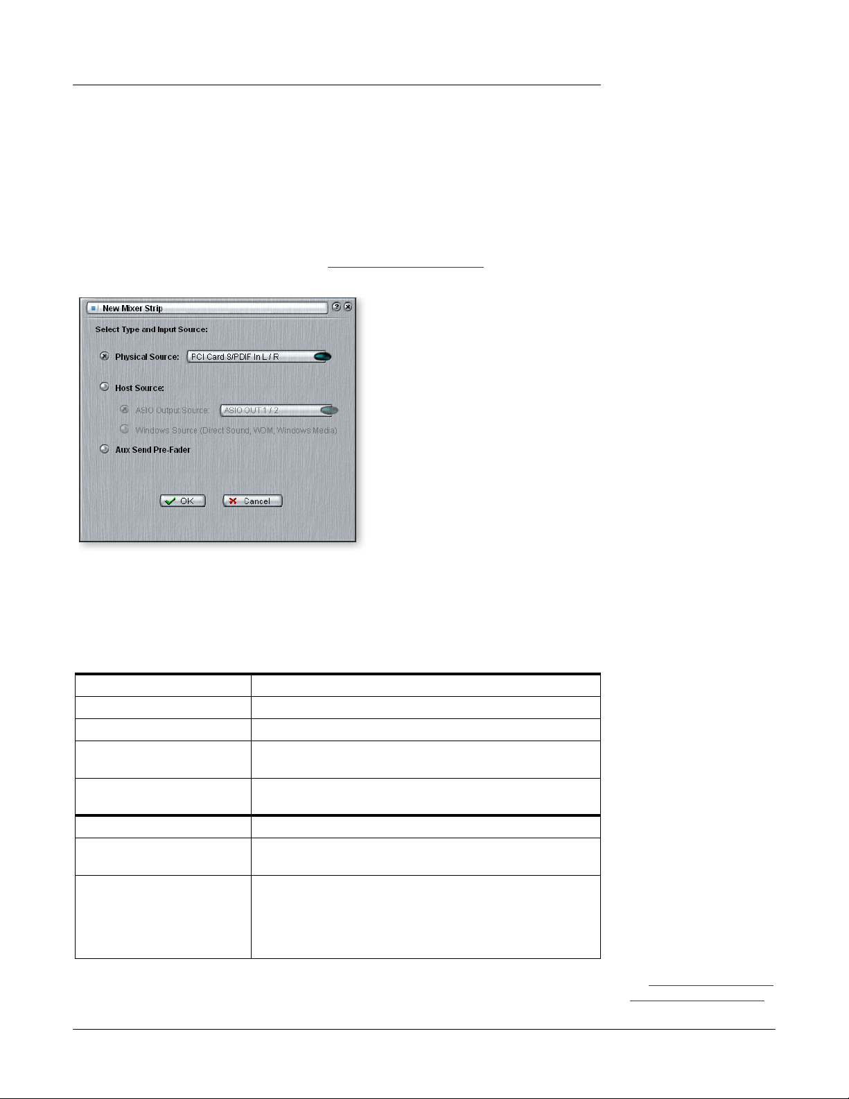
To Add a New Strip:
1. Click on the New Mixer Strip button. See Overview of the Mixer. The New Mixer
Strip Input Dialog appears:
4 — The PatchMix DSP Mixer
Mixer Strip Creation
f Adding or deleting a
strip “defragments” the
effect/DSP resources. If
any effect you wish to
add is unavailable
(greyed-out), try deleting
an unused strip to free up
resources.
2. Select the desired input to the mixer strip from the following choices:
• Physical Source: Analog or digital input (Analog, ADAT, S/PDIF)
• Host — ASIO Source input Streaming audio from an ASIO software application.
• Host — WAVE input Window sound sources — WAVE, WDM, CD
PHYSICAL SOURCE Function
Physical: Dock Mic/Line 24-bit monophonic analog input on the MicroDock.
Physical: Dock In 24-bit stereo analog input on the MicroDock.
Physical: Dock S/PDIF 2 channel digital audio from the S/PDIF input on the
Physical: Dock ADAT 2 channel (x4 strips) digital audio from the ADAT input on
HOST SOURCE Function
Host ASIO Output Source
From software application
Host Windows Source
From Windows
3. Select Pre-Fader Aux Sends or leave the box unchecked for Post-Fader Aux Sends.
4. Click OK to create a new strip or Cancel to cancel the operation.
E-MU 1616/1616M CardBus Digital Audio System 29
MicroDock.
the MicroDock.
2 channel digital audio from an ASIO source (software app).
ASIO: 1/2, 3/4, 5/6, 7/8, 9/10, 11/12, 13/14, 15/16
Direct Sound, WDM, Windows Media
(Sound generated or handled by Windows.)
WAVE 1/2 — Default stereo source such as game sound, CD
player, beep sounds, etc.
WAVE 3/4, WAVE 5/6, WAVE 7/8 — Additional WDM channels
f See “Pre or Post Fader
Aux Sends” on page 40.
4 — The PatchMix DSP Mixer
Mixer Strip Creation
To Delete a Mixer Strip:
1. Click the top of the mixer strip you wish to delete. A red border appears around
the strip, indicating that it is selected.
2. Click on the Delete Mixer Strip button, or right-click and choose Delete, or use the
Delete key on the PC keyboard. See Overview of the Mixer.
Multichannel WAVE Files
The 1616 supports 2 channels of WAVE recording and 8 channels of multichannel
WAVE playback. The WAVE channels are available for the following types of WDM
devices:
• Classic MME
• DirectSound
• Direct WDM / Kernel Streaming (KS)
DirectSound and the WDM/KS interfaces allow up to Eight channels of Wave Out
while the classic MME interface only exposes 2 channels.
The WAVE channels operate at all sample rates. For additional information about WDM
behavior at high sample rates, see page 81.
192kHz/96kHz DVD-Audio disks are protected against digital copying. Most DVDAudio disks contain duplicate 48kHz audio tracks which will play back on the 1616.
Windows Media Player/DVD/Surround Sound Playback
Select DirectSound as the output format when using Windows Media Player and other
DVD player applications.
Eight channel WAVE playback supports either 5.1, 6.1 or 7.1 surround audio. However,
the 1616 is best suited to play 5.1 surround, since it only has 6 analog outputs. (You
could play back 7.1 surround audio by using an external S/PDIF to Analog Converter.
Create a 7/8 WAVE strip and insert a Send to S/PDIF Out.)
The chart below shows how to connect the outputs for 5.1 surround sound playback.
Multichannel WAVE to Surround Sound Speaker Channels
(using the factory 5.1 DVD Playback Session)
WAVE Strip Surround Channels 1/4” Outputs 1/8” Outputs
E-DSP WAVE 1/2 Front Left / Front Right 1L = FL 1R = FR 1 (Tip = FL Ring = FR)
E-DSP WAVE 3/4 Center / Subwoofer 3L = C 3R = Sub 3 (Tip = C Ring = Sub)
E-DSP WAVE 5/6 Rear Left / Rear Right 2L = RL 2R = RR 2 (Tip = RL Ring = RR)
E-DSP WAVE 7/8 Side Left / Side Right N/A N/A
30 Creative Professional
Loading…
-
-
#1
Всем доброго времени суток.
Очень надеюсь на поддержку соображающих людей, подключение ЕМУ оказалось просто казнью.
Что бы не читал в инете и как бы не пытался сам настроить звук, ничего не получаеться (((
Итак начну сначала: в карту 1010 вставлен коаксиальный СПДИФ в out, в микродок он вставлен СПДИФ in на передней части карты, микродок подключен к колонкам через разьем 3.5 мм( временно, потом буду подключать к усилителю с норм мониторами).
Установил драйвера и дсп патчмикс, в диспетчере устройств устройство отображается, отключил драйвер realtek, но, в дсп патчмиксе горит зеленая лампочка только на внутренюю карту (1010), остальные не горят.
Открываю google chrome и на нем включаю музыку для теста, звук отображается как в настройках звука в виндоус (7) , так и в дсп патчмикс (играет WAVE).
А вот что делать дальше не понятно вообще, как сделать сенд , откуда и куда. Может что то и не работает, но это можно узнать только метедом тыка и правильного подключения, которое я не могу сделать самостоятельно.
я уже перетыкал все что можно и результата ноль .
ПОЖАЛУЙСТА ПОМОГИТЕ!
-
Безымяkljj;kljнный.jpg
81,1 KB
· Просмотры: 217
-
Безымяkljнный.jpg
71,6 KB
· Просмотры: 213
-
Безымяннk;klljlkjый.jpg
145,9 KB
· Просмотры: 210
-
Безымяннkljlkjый.jpg
237 KB
· Просмотры: 219
-
-
#2
в карту 1010 вставлен коаксиальный СПДИФ в out, в микродок он вставлен СПДИФ in на передней части карты,
это неверно, микродок и карта соединяются только своим кабелем и работают как одно целое. У вас микродок не подключен, соответственно работать не будет.
-
-
#3
что значит своим кабелем? есть какой то EDI — это он?
-
-
#5
Я купил карту с рук , мануала не было и блока питания тоже( БП купил), есть только МИДИ кабель и EDI.
Подключил 1010 и микродок через EDI , звук отсутствует.
[DOUBLEPOST=1484253521][/DOUBLEPOST]Кстати благодарю за мануал)
-
-
#6
на ваших скринах микродок не подключен
-
-
#7
Подключил EDI, перезалил драйвера, теперь микродок обнаружен. Ура!
Звук появился по данной схеме.
BasbIl благодарю за подсказку, тяжко жить с железобетонными мозгами в наше время))
если можно задам еще вопрос — карая разница в пути к разьему mix и mon ( на скрине стоит mon)
, они работают оба но все же для понимания схем.
-
Безымuytuянный.jpg
143,6 KB
· Просмотры: 223
-
-
#8
@Malahit, в пути — никакой, MON регулируется ручкой Monitor Volume, которая считается системным регулятором громкости (со всеми вытекающими плюшками).
-
-
#9
Еще проблема выявилась.
Одна колонка играет тише другой, баланс везде нормальный, меняю провода от колонок местами в усилителе, левый работает громче правого, подключаю звук без ЕМU к усилителю, все нормально.
-
-
#10
@Malahit, до того, как колонки меняли местами дисбаланс тот же был?
Если выход емушки громче тот же самый, то гляньте, не навставляли ли инсертов и обработки — могут влиять.
Если нет — одинаковые ли провода…
-
-
#11
Еще проблема выявилась.
Одна колонка играет тише другой, баланс везде нормальный, меняю провода от колонок местами в усилителе, левый работает громче правого, подключаю звук без ЕМU к усилителю, все нормально.
Подозреваю что это возможно из за физического устаревания каких то элементов в схеме) прошу прощения за техническую безграмотность, «гуманитарий», ничего тут не поделаешь. Просто у самого лежит 0404 USB, которой пользуюсь раз в года два наверное, когда поехать на долго куда то нужно, ну и чтоб не скучать беру ноут и ее)), и в крайней поездке тоже обнаружил такую проблему — один канал тише другого. Коммутация исключена (брал ту, которую дома использую), остается сама карта. Лично меня нисколько не удивляет такая возможность, картам сто лет в обед, мало ли, кондеры «подсохли», или еще чего)
-
-
#12
@Kosten, там, на выходе аналоговых каналов, стоят так называемые «mute» ключи, это транзисторы, которые замыкают выход на «землю» в момент всяческих перекоммутаций и переходных процессов.
Небольшой офф.
В наших условиях эксплуатации, когда зачастую в сетевой розетке отсутствует заземление, на корпусе компьютера, как и некоторых прочих устройств с встроенными импульсными блоками питания, имеется паразитное напряжение, величиной порядка половины напряжения в электросети. Оно образуется из-за наличия в входном фильтре Y-конденсаторов за «землю», которые должны сливать помехи с питающих линий на заземляющий проводник. Но если «земли» нет — то образуется паразитный делитель напряжения ~U/2, который подключен к металлическому шасси(корпусу).
Собственно немногобукв кончились. Теперь суть.
Если коммутировать устройства подключенные к электросети, но имеющие разные потенциалы, то возможны всяческие приключения со сгоранием всего, чего только можно.
В данном случае — скорее всего выгорели эти «mute»-ключи, как показывает печальная статистика, личная в том числе.
Но трагичного нет ничего — просто выпаиваем(выкусываем) их и вуаля! Да, бывает, что и разделительные конденсаторы вздувает, если таковые имеются. Их менять.
Последнее редактирование:
tmk
Active Member
-
-
#13
@mexap, таки в итоге что с землей то делать, если её нет в проводке, и возможности провести нет?
-
-
#14
@tmk, отключаем от розетки и только после этого осуществляем всю коммутацию. Разве из прошлого моего ответа это не очевидно?
Последнее редактирование:
-
-
#15
Если коммутировать устройства подключенные к электросети, но имеющие разные потенциалы, то возможны всяческие приключения со сгоранием всего, чего только можно. В данном случае — скорее всего выгорели эти «mute»-ключи, как показывает печальная статистика, личная в том числе.
Такое «приключение» тоже было с 1820, я ее отцу отдал, выходов там в избытке, его никак не огорчает что один из них не работает. Я и не знал что это можно вылечить, но в данном случае и не надо это никому.
Но там этот канал он практически не слышен становится, а вот с 0404 там просто слегка тише, точно не замерял, но % на 10 может примерно
-
-
#16
@Kosten, суть приключения скорее всего одна и та же. И рецепт тоже.
Офф: у меня, кстати, на прошлой 1616, из-за сильного перекоса питающих фаз или ещё чего подобного на репетиционной точке(трамвайное депо, ~400Гц вечная наводка), вообще выжгло два развязывающих резистора по питанию ОУ одного канала, до полной неработоспособности одного выхода, думал совсем беда — разобрал/разобрался — подлечил.
Последнее редактирование:
-
-
#17
выходов вагон, воткните в рабочие. Роутинг конфижится.
-
-
#18
@tmk, отключаем от розетки и только после этого осуществляем всю коммутацию. Разве из прошлого моего ответа это не очевидно?
Подключение с отключенными розетками вроде бы помогло.
По крайней мере через подключение микродока джеком 3.5 воткнутым в усилок входом DIM.
Но, проблема видимо в моей попытке подключиться более качественными проводами — microdock out Jack 6.5 mono x 2 => In на уситлителе RSA x 2, при попытке сменить out на микродоке проблема осталась.
Может быть проблема из-за моно проводов? Сигналы то по идее моно идут.
-
-
#19
@Malahit, в вашем случае «поздно пить боржоми» — нужен ремонт неисправных выходов.
-
-
#20
не могут же все выходы быть неисправны. Понаделают блин, а потом себе и всем кому возможно мозг кипятишь…

E-MU 1616/1616M CardBus Digital Audio System
1
Owner’s Manual
Digital Audio System
Аудиоинтерфейс PCI (с внешним конвертором) является ведущей в линейке цифровых аудиосистем от E-MU, обеспечивая вам все необходимое для создания профессионального аудио на вашем ПК: 24-битные/192кГц-конвертеры (те же А/Ц-конвертеры используются в интерфейсе ввода/вывода ProTools Digidesign HD 192 I/O), эффекты и микширование с аппаратным ускорением, полный набор опций синхронизации и идеальная совместимость с вашими любимыми аудио/секвенсерными программами ПК. Ни одно другое аудио решение не может обеспечить характеристики работы, гибкость в сочетании с ценой, как система E-MU 1616M PCI.
Система предельно портативна: для записи, редактирования, микширования и виртуальных инструментов вы можете использовать плату E-MU 02 CardBus автономно для эффектов с аппаратным ускорением и высококачественного выхода стереонаушников/линейного выхода, либо совместно с боксом MicroDock M, получая тем самым полную гибкость аналоговых и цифровых входов и выходов
Эффекты с аппаратным ускорением — свыше 600 автономных и подключаемых эффектов E-MU Power FX VST, не требующих надстройки CPU
PatchMix™ DSP — аппаратное микширование и мониторинг с нулевым временем ожидания при помощи супергибкой панели — внешний микшер не требуется
Сверхпортативный бокс MicroDock M обеспечивает 16 входов/16 выходов плюс входы/выходы MIDI — все, от балансных аналоговых входов и входов проигрывателя до ADAT и S/PDIF (переключаются в AES/EBU)
Два предварительных усилителя E-MU XTC™ студийного класса, сверхнизкого уровня шума (-127дБu EIN) с мягким аналоговым ограничителем — микрофонный/линейный и прямые Hi-Z входы через коннекторы Neutrik, фантомное питание 48В и 60дБ усиления
Совместимость с наиболее распространенными аудио/секвенсерными приложениями — драйверы для 24-бит/192кГц ASIO 2.0 со сверхнизким временем ожидания и стерео-WDM
Пакет программных инструментов E-MU: включает в себя Cakewalk SONAR LE, Steinberg Cubase LE и Wavelab Lite, Ableton Live Lite 4 для E-MU, IK Multimedia AmpliTube LE и T-RackS EQ, Minnetonka diskWelder BRONZE, SFX Machine LT, плюс звуковой модуль рабочего стола Proteus X LE Desktop — все, что вам необходимо для создания, записи, редактирования, мастеринга и программирования сведено в один бокс.
Эффекты с аппаратным ускорением, микширование и мониторинг E-DSP: Цифровые аудиосистемы для ноутбуков от E-MU оснащены мощным чипсетом E-DSP, имеющим процессор эффектов с аппаратным ускорением с более чем 28 подключениями эффектов (более 600 преднастроек). Данная архитектура эффектов полностью расширяемая, она позволяет добавлять по мере необходимости дополнительные подключения эффектов к вашей системе. E-DSP также обеспечивает аппаратное микширование и мониторинг с нулевым временем ожидания через прилагаемый микшер PatchMix DSP, что дает уникальную гибкость в маршрутизации аудио между вашими материальными и виртуальными (ASIO/WDM) входами и выходами без использования внешнего микшера.
Технические характеристики
Кол-во I/O: 16/16
АЦП/ЦАП: конверторы Digidesign
Входы: 2MIC+6 вх. аналоговых (14 TRS балансный), ADAT (TosLink), S-PDIF (RCA)
Выходы: 8 аналоговых вых.(14 TRS балансный), ADAT (TosLink), S-PDIF (RCA)
MIDI: MIDI 2IN/2OUT
Интерфейс: PCI
Синхронизация: ADAT, S-PDIF
Драйверы: Win&MAC
Размеры: 150x265x300
Вес: 2,5