
Терморегуляторы с установкой на DIN-рейку EMKO ESM-1510-N представляют собой простейшие двухпозиционные (ON/OFF) измерители-регуляторы температуры.
Простота настройки, стандартизованный размер корпуса (габариты совпадают с размерами стандартных автоматических выключателей) и невысокая стоимость позволяют применять данную серию регуляторов в самых различных областях.
Наиболее широко терморегуляторы ESM-1510-N на DIN-рейку используются в простейших системах вентиляции, в холодильном оборудовании, в простых печах и сушильных шкафах, а также для контроля температуры в шкафах автоматики и серверных помещениях.
Дополнительно терморегуляторы при работе в режиме «холодильник» имеют расширенный функционал для защиты компрессора и функцию задания состояния выхода при обрыве датчика. Благодаря этой особенности терморегуляторы ESM-1510-N нашли широкое применение в холодильной технике. Данный регулятор, с тем же функционалом, представлен контроллером температуры холодильного оборудования для монтажа в шкафу.
Измерители-регуляторы просты в настройке и дополнительно имеют функцию ограничения доступа от несанкционированного входа в параметры.
- установка терморегулятора на DIN рейку;
- легкий ввод в эксплуатацию;
- 2-х позиционное (ON/OFF) регулирование;
- тип входа определяется при заказе, не требует настройки;
- два режима работы: «нагреватель», «холодильник»;
- защита паролем от несанкционированного доступа к параметрам;
- функции управления и защиты компрессора:
- предохранение компрессора от частых запусков;
- предохранение компрессора при выходе датчика из строя;
- задержка включения компрессора при включении питания.
| Параметр | Значение |
|---|---|
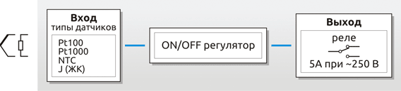
| Измерительный вход (выбирается при заказе) | ТП: J (ЖК); ТС: Pt100 (2-х пров.), Pt1000, NTC (10 кОм) |
| Предел основной приведенной погрешности | ±1% |
| Метод регулирования | ON/OFF (двухпозиционный) |
| Выход | реле (5 А при ∼250 В, активная нагрузка) |
| Напряжение питания | ∼230 В (±15%), 50/60 Гц |
| Потребляемая мощность | 1,5 ВА |
| Окружающая среда | рабочая температура: (0…+50) °C температура хранения: (-40…+85) °C относительная влажность: (0…90)% (без образования конденсата) |
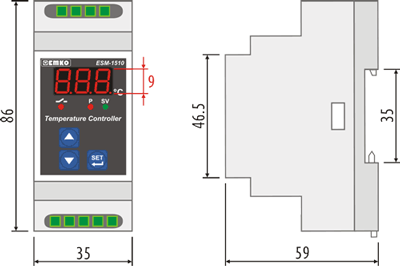
| Индикация | красный 3-х разрядный LED индикатор |
| Габаритные размеры (ШхВхГ) | 35×86×59 мм, пластиковый корпус с установкой на DIN-рейку |
| ESM-1510-N.5. | .0.1/00.00/2.0.0.0 | |
|---|---|---|
| Тип измерительного входа | ||
| J (ЖК) (0…800) °C | 05 | |
| Pt-100 (-19,9…99,9) °C | 09 | |
| Pt-100 (-50…400) °C | 11 | |
| Pt-1000 (-19,9…99,9) °C | 13 | |
| NTC (-19,9…99,9) °C | 18 |
Пример: ESM-1510-N.5.13.0.1/00.00/2.0.0.0
|
ESM 1510 Контроллеры температуры серии ESM-1510 разработаны для измерения и контроля температуры. Могут быть использованы в следующих отраслях промышленности: • Производство стекла контроль нагрева • Пищевая промышленность контроль температуры печей • Производство пластика поддержка темп-ры в инкубаторах • Нефтехимическое производство температура на складах • Текстильная промышленность вентиляция и кондиционирование • Автомобильная промышленность |
Скачать |
Контроллеры Emko предназначены для различных сфер деятельности: коммерческой, промышленной, бытовой. А значит в каждом аппарате с которым будет взаимодействовать данный технический элемент есть свои особенности. Для того, чтобы вникнуть во все тонкости, специалисты рекомендуют скачать инструкцию по эксплуатации, в которой выстроен целый алгоритм действ, позволяющие облегчить понимание работы установки. Инструкция предоставляется на русскому языке в знакомом всем формате pdf-файла. Даже самые продвинутые пользователи, которые ранее встречались с подобной техникой, все равно используют время от времени специальный мануал.
E
S
M
-1
5
1
0
D
IN
R
a
il
M
o
u
n
ti
n
g
T
e
m
p
e
ra
tu
re
C
o
n
tr
o
ll
e
r
— 3 Digits display
— NTC Input or,
PTC Input or,
J type thermocouple Input or,
K type thermocouple Input or,
2-Wire PT 100 Input or,
2-Wire PT 1000 Input (It must be determined in order)
— ON/OFF temperature control
— Selectable heating or cooling function
— Selection of operation with hysteresis
— Adjustable temperature offset
— Set value low limit and set value high limit boundaries
— Relay or SSR driver output
— Operation selection of compressor operates continuously, stops
or operates periodically in case of probe defect
— Compressor protection delays
— Password protection for programming mode
Instruction Manual. ENG ESM-1510 02 V08 08/14
ESM-1510 DIN Rail Mounting Type
Digital, ON / OFF Temperature Controller
ESM-1510-N.5.11.0.1/00.00/2.0.0.0 Измеритель-регулятор температуры, DIN рейка (вход Pt100 (-50…+400 C, 2-х пров.), выход: реле (НО+НЗ, 5А), питание 230 VAC, кл. 1)
Терморегуляторы с установкой на DIN-рейку EMKO ESM-1510-N представляют собой простейшие двухпозиционные (ON/OFF) измерители-регуляторы температуры.
Простота настройки, стандартизованный размер корпуса (габариты совпадают с размерами стандартных автоматических выключателей) и невысокая стоимость позволяют применять данную серию регуляторов в самых различных областях.
Наиболее широко терморегуляторы ESM-1510-N на DIN-рейку используются в простейших системах вентиляции, в холодильном оборудовании, в простых печах и сушильных шкафах, а также для контроля температуры в шкафах автоматики и серверных помещениях.
Дополнительно терморегуляторы при работе в режиме «холодильник» имеют расширенный функционал для защиты компрессора и функцию задания состояния выхода при обрыве датчика. Благодаря этой особенности терморегуляторы ESM-1510-N нашли широкое применение в холодильной технике. Данный регулятор, с тем же функционалом, представлен контроллером температуры холодильного оборудования для монтажа в шкафу.
Измерители-регуляторы просты в настройке и дополнительно имеют функцию ограничения доступа от несанкционированного входа в параметры.
| Параметр | Значение |
|---|---|
| Измерительный вход (выбирается при заказе) | ТП: J (ЖК); ТС: Pt100 (2-х пров.), Pt1000, NTC (10 кОм) |
| Предел основной приведенной погрешности | ±1% |
| Метод регулирования | ON/OFF (двухпозиционный) |
| Выход | реле (5 А при ∼250 В, активная нагрузка) |
| Напряжение питания | ∼230 В (±15%), 50/60 Гц |
| Потребляемая мощность | 1,5 ВА |
| Окружающая среда | рабочая температура: (0…+50) °C температура хранения: (-40…+85) °C относительная влажность: (0…90)% (без образования конденсата) |
| Индикация | красный 3-х разрядный LED индикатор |
| Габаритные размеры (ШхВхГ) | 35×86×59 мм, пластиковый корпус с установкой на DIN-рейку |
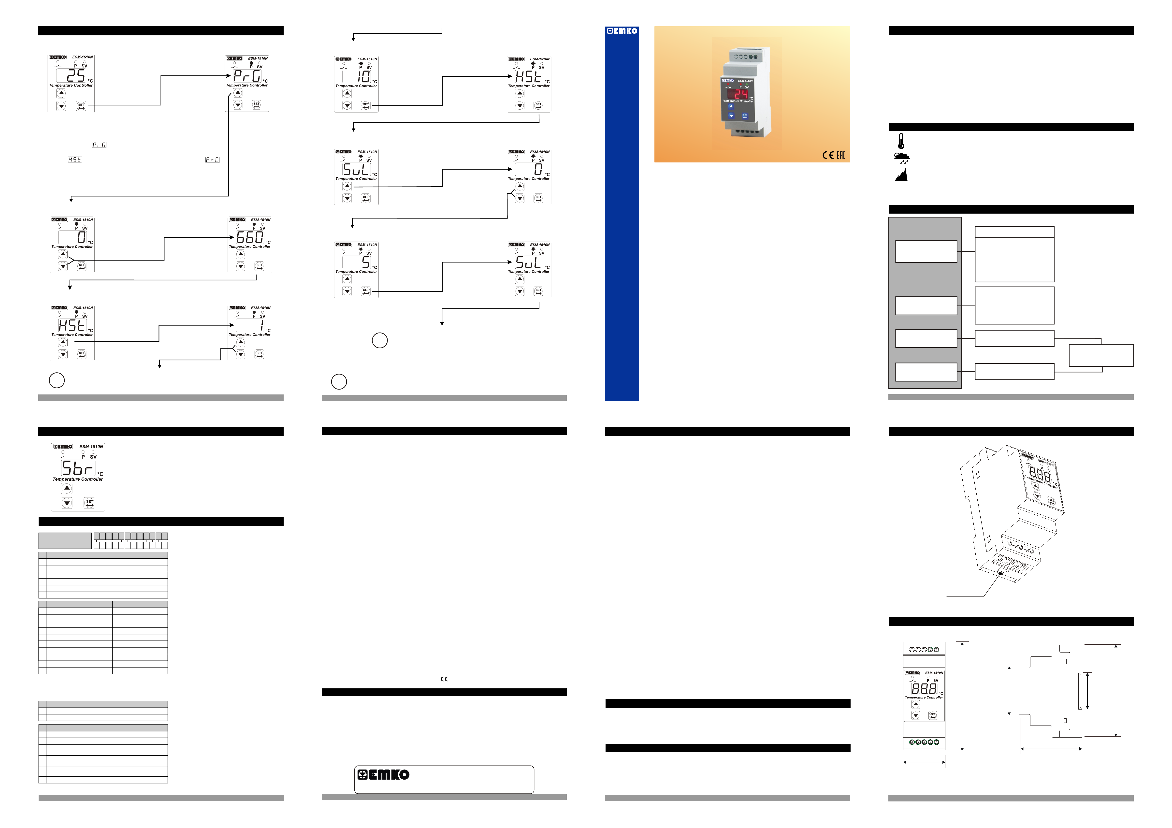
4.6 Entering To The Programming Mode, Changing and Saving Parameters
1.Preface
Operation Screen
Press increment button
for accessing to the
password entering
5 secs
screen.
When SET button is pressed for 5
seconds, “P” led starts to blink. If
programming mode entering password is
different from 0, programming mode
entering screen will be observed.
Note-1: If programming mode accessing password is 0, hysteresis
screen is observed instead of Programming screen
accessing password
Note-2: Parameters can be observed by pressing SET/OK button in
password entering screen without entering the programming mode
entering password. But parameters can not be changed.
Password Entering
Screeen
Enter programming
mode accessing
password with
increment and
decrement buttons
Press SET/OK button
for accessing to the
parameters
Hysteresis Parameter
Parameter is accessed
by pressing increment
button. If set button is
pressed, next
parameter is shown.
Change the
parameter with
increment and
decrement buttons
If no operation is performed in Programming mode for 20 seconds, device turns to
i
operation screen automatically
Programming Mode
Entering Screen
Password Entering
Screeen
Hysteresis Parameter
Value
Hysteresis Parameter
Value
saving the parameter
Minimum Set Value
Parameter
accessed by pressing
set button is pressed,
Minimum Set Value
saving the parameter
i
If no operation is performed in Programming mode for 20 seconds, device turns to
i
operation screen automatically
Hysteresis Parameter
Press Set button for
value
Press Set button for
accessing to the next
parameter
Minimum Set Value
Parameter is
increment button. If
next parameter is
shown.
Change the
parameter with
increment and
decrement buttons
Minimum Set Value
Parameter
Press Set button for
value
Other Programming mode parameters can be accessed
with the same method explained above, observed and
changed.
ESM-1510N DIN Rail Mounting Temperature Controller
ESM-1510N DIN Rail Mounting Type
Digital, ON / OFF Temperature Controller
— 3 Digits display
— NTC Input or,
PTC Input or,
J type thermocouple Input or,
K type thermocouple Input or,
2-Wire PT 100 Input or,
2-Wire PT 1000 Input (It must be determined in order)
— ON/OFF temperature control
— Selectable heating or cooling function
— Selection of operation with hysteresis
— Adjustable temperature offset
— Set value low limit and set value high limit boundaries
— Relay or SSR driver output
— Operation selection of compressor operates continuously, stops
or operates periodically in case of probe defect
— Compressor protection delays
— Password protection for programming mode
ESM-1510N series temperature controllers are designed for measuring and controlling
temperature. They can be used in many applications with their On / Off control form, heating and
cooling control form and easy-use properties. Some application fields which they are used are
below:
Application Fields Applications
Glass Heating
Food Baking Ovens
Plastic Incubators
Petro-Chemistry Storages
Textile, Automative Air Conditioning
Machine Production Industries Etc…
Etc…
1.1 Operating Conditions
Operating Temperature : 0 to 50 °C
Max. Operating Humidity : 90% Rh (non-condensing)
Altitude : Up to 2000 m.
Forbidden Conditions:
Corrosive atmosphere, Explosive atmosphere,
c
Home applications (The unit is only for industrial applications)
1.2 General Specifications
Standard
ESM-1510N
230 V V (±%15) , 50/60Hz
Optional Supply Input
Power Supply
Input
Temperature Sensor
Input
Standard
Output-1
(Relay Output)
Optional
Output-1
(SSr Driver Output)
115 V V (±%15) , 50/60Hz
24 V V (±%15) , 50/60Hz
24 V W (-%15, +%10),
50/60Hz
10…30 V Z
NTC
PTC
J or K Type TC
2-wire PT 100
2-wire PT 1000
Control Output
Alarm Output
Heating or Cooling
Function
ON/OFF Operation
Control Output
Alarm Output
5. Failure Messages in ESM-1510N Temperature Controller
Probe defect in analogue inputs. Sensor connection is wrong or
there is no sensor connection.
6. Ordering Information
U
V W Z/
/
Temperature Controller are given on the
All order information of ESM-1510N
ESM-1510N (77×35 DIN Size)
A BC D E FG HI /
0 00 2 0 0
00
/
table at left. User may form appropriate
Supply VoltageA
24V W ( -15%,+10% ) 50/60Hz
2
24V V ( ± 15% ) 50/60Hz
3
115V V ( ± 15% ) 50/60Hz
4
230V V ( ± 15% ) 50/60Hz
5
10…30 V Z
8
9
Customer
Input Type
BC
J ,Fe CuNi IEC584.1(ITS90)
05
10
K ,NiCr Ni IEC584.1(ITS90)
PT 100 , IEC751(ITS90)
11
PT 100 , IEC751(ITS90)
09
PTC (Note-1)
12
PTC (Note-1)
15
PT 1000 , IEC751(ITS90)
14
PT 1000 , IEC751(ITS90)
13
NTC (Note-1)
18
19
NTC (Note-1)
Note-1 : If input type is selected PTC or NTC (BC = 12, 15, 18, 19 ),
Temperature sensor is given with the device. For this reason,
If input type is selected as PTC, sensor type (V = 0,1 or 2) or
If input type is selected as NTC, sensor type (V = 0,3 or 4) must be
declared in ordering information.
E
Output-1
1
Relay Output ( resistive load 10 A@250 V V , 1 NO + 1NC )
2
SSR Driver Output (Maximum 28 mA, 15 V Z)
Temp. Sensor which is given with ESM 1510
V
None
0
PTC-M6L40.K1.5 (PTC Air Probe with 1.5 m silicon cable)
1
PTCS-M6L30.K1.5.1/8” (PTC Liquid Probe with 1.5 m silicon
2
cable)
NTC-M5L20.K1.5 (NTC Probe, thermoplastic moulded with
3
1.5 m cable for cooling application)
NTC-M6L50.K1.5 (NTC Probe, stainless steel housing with
4
1.5 m cable for cooling application)
Customer
9
Scale(°C)
0°C
0°C
-50°C
-19.9°C
-50°C
-19.9°C
-50°C
-19.9°C
-50°C 100°C
-19.9°C 99.9°C
800°C
999°C
400°C
99.9°C
150°C
99.9°C
400°C
99.9°C
device configuration from information and
codes that at the table and convert it to the
ordering codes.
Firstly, supply voltage then other
specifications must be determined. Please
fill the order code blanks according to your
needs.
Please contact us, if your needs are
out of the standards.
c
V Symbol means Vac,
Z Symbol means Vdc,
Symbol means Vac/dcW
13
15
14
7. Specifications
Device Type : Temperature Controller
Housing&Mounting : 86mm x 35mm x 59mm plastic housing for Rail Mounting.
Protection Class : IP20.
Weight : Approximately 0.14 Kg.
Environmental Ratings : Standard, indoor at an altitude of less than 2000 meters
with none condensing humidity.
Storage / Operating Temperature: -40 C to +85 C / 0 C to +50 C
oooo
Storage / Operating Humidity : 90 % max. (None condensing)
Installation : DIN Rail Mounting
Overvoltage Category : II.
Pollution Degree : II, office or workplace, none conductive pollution
Operating Conditions : Continuous
Supply Voltage and Power : 230 V V (± 15%) 50/60 Hz. 1.5 VA
115 V V (± 15%) 50/60 Hz. 1.5 VA
24 V V (± 15%) 50/60 Hz. 1.5 VA
24 V W (- 15%, + 10%) 50/60 Hz. 1.5 VA
10…30 V Z 1.5 W
Temperature Sensor Inputs : NTC, PTC, TC, RTD
NTC Input Type : NTC (10 kW @.25 °C )
PTC Input Type : PTC (1000 W @.25 °C )
Thermocouple Input Types : J, K (IEC584.1)(ITS90)
Thermoresistance Input Type : PT-100, PT-1000 (IEC751)(ITS90)
Accuracy : ±1% of full scale for thermocouple and thermoresistance
Cold Junction Compensation : Automatically ± 0.1°C/1°C.
Sensor Break Protection : Upscale
Sampling Cycle : 3 samples per second
Control Form : ON / OFF
Relay Output : Resistive Load 5 A@250 V V
(Electrical Life : 100.000 operation (Full Load)
Optional SSR Output : Maximum 28 mA, Maximum 15 V Z
Display : 9 mm Red 3 digits LED Display
Leds : SV (Green) , OUT (Red) , P(Red) 3 mm
Approvals : GOST-R,
8. Other Informations
Manufacturer Information:
Emko Elektronik Sanayi ve Ticaret A.Þ.
Demirtaþ Organize Sanayi Bölgesi Karanfil Sk. No:6 16369 BURSA / TURKEY
Tel : +90 224 261 1900
Fax : +90 224 261 1912
Repair and maintenance service information:
Emko Elektronik Sanayi ve Ticaret A.Þ.
Demirtaþ Organize Sanayi Bölgesi Karanfil Sk. No:6 16369 BURSA / TURKEY
Tel : +90 224 261 1900
Fax : +90 224 261 1912
Thank you very much for your preference to
use Emko Elektronik products, please visit our
Your Technology Partner
web page to download user manual.
www.emkoelektronik.com.tr
16
Instruction Manual. ENG ESM-1510N 01 V00 02/16
1.3 Installation
Before beginning installation of this product, please read the instruction
c
manual and warnings below carefully.
In package ,
— One piece unit
— One piece rail lock apparatus
— One piece instruction manual
A visual inspection of this product for possible damage occured during shipment is
recommended before installation. It is your responsibility to ensure that qualified
mechanical and electrical technicians install this product.
If there is danger of serious accident resulting from a failure or defect in this unit, power
off the system and separate the electrical connection of the device from the system.
The unit is normally supplied without a power supply switch or a fuse. Use power switch
and fuse as required.
Be sure to use the rated power supply voltage to protect the unit against damage and to
prevent failure.
Keep the power off until all of the wiring is completed so that electric shock and trouble
with the unit can be prevented.
Never attempt to disassemble, modify or repair this unit. Tampering with the unit may
results in malfunction, electric shock or fire.
Do not use the unit in combustible or explosive gaseous atmospheres.
During the equipment is putted in hole on the metal panel while mechanical installation
some metal burrs can cause injury on hands, you must be careful.
Montage of the product on a system must be done with it’s fixing clamps. Do not do the
montage of the device with inappropriate fixing clamp. Be sure that device will not fall
while doing the montage.
It is your responsibility if this equipment is used in a manner not specified in this
instruction manual.
1.4 Warranty
EMKO Elektronik warrants that the equipment delivered is free from defects in material and
workmanship. This warranty is provided for a period of two years. The warranty period starts from
the delivery date. This warranty is in force if duty and responsibilities which are determined in
warranty document and instruction manual performs by the customer completely.
1.5 Maintenance
Repairs should only be performed by trained and specialized personnel. Cut power to the device
before accessing internal parts.
Do not clean the case with hydrocarbon-based solvents (Petrol, Trichlorethylene etc.). Use of
these solvents can reduce the mechanical reliability of the device. Use a cloth dampened in ethyl
alcohol or water to clean the external plastic case.
3
2 General Description
Rail Lock Apparatus
2.1 Front View and Dimensions of ESM-1510N Temperature Controller
78910
6
46.5 mm / 1.83 inch
90 mm / 3.54 inch
3
2
5
41
61.2 mm / 2.40 inch
35 mm / 1.38 inch
2
35.7 mm / 1.40 inch
90 mm / 3.54 inch
4
2.2 Installation onto the Rail
The unit is designed for rail mounting.
1- Put into the unit upper side of the
rail properly.
2- Pull down the rail lock apparatus
via a screw driver.
3.-Push the unit from the underside
for mounting to the rail.
During installation onto the rail, care should be taken to avoid injury from
mechanical part of the system. These precautions for the safety of the person
c
2.3 Removing from the Rail
2.5 Panel Mounting
who does the rai mounting.
Before starting to remove the unit from the rail, power off the unit and the
related system.
c
1- Pull down the rail lock apparatus
via a screw driver.
2- Pull the unit from the underside to
seperate the rail lock apparatus from
the rail
3.- Pull up the unit to remove from the
rail.
3. Electrical Wiring Diagram
Temperature Sensor Input
(TC, NTC, PTC, PT-100 or PT-1000)
7
6
TC
NTC, PTC, PT-100, PT1000
1
ÇIKIÞ
5 A@250 V V
aa
3
Supply Voltage Input
2
230 V V ( ± %15 ) 50/60 Hz — 1.5 VA
115 V V ( ± %15 ) 50/60 Hz — 1.5 VA
24 V V ( ± %15 ) 50/60 Hz — 1.5 VA
24 V W ( -%15, +%10 ) 50/60 Hz — 1.5 VA
10…30 V — 1.5 WZ
3.1 Supply Voltage Input Connection of the Device
L(+) N(-)
NONCC
2341
5
(+)
(-)
Relay or SSR Driver Output
For SSr Output
4.2 Changing and Saving Set Value
Operation Screen
When SET button is
pressed, SV LED
lights on and SET
value is shown on the
displays.
SET Value Screen
SET Value Screen
Change the SET value with
increment and decrement buttons.
Operation Screen
Y
a
1
External
Fuse
(1 A T)
3
Supply Voltage
230 V V (± 15%) 50/60 Hz or
115 V V (± 15%) 50/60 Hz or
24 V V (± 15%) 50/60 Hz or
24 V W (-15%,+10%) 50/60 Hz or
10…30 V — 1.5 WZ
Make sure that the power supply voltage is same indicated on the instrument.
Switch on the power supply only after that all the electrical connection have been completed.
Supply voltage range must be determined in order. While installing the unit, supply voltage range must be
controlled and appropriate supply voltage must be applied to the unit. Controlling prevents damages in unit
and system and possible accidents as a result of incorrect supply voltage.
2
1
There is no power supply switch or fuse on the device. So a power supply switch and a fuse must be added
to the supply voltage input. Power supply switch and fuse must be put to a place where user can reach
easily. Power supply switch must be two poled for seperating phase and neutral. On/Off condition of power
supply switch is very important in electrical connection. On/Off condition of power supply switch must be
signed for preventing the wrong connection.
NL
2
Note-2
Note-1
Power
Supply
Switch
c
Note-1:
24V Supply Voltage
Note-2: External Fuse is recommended
Note-3: External fuse must be on phase connection in
Vsupply input.
Note-4: External fuse must be on (+) line connection in
Zsupply input.
“L” is (+), “N” is (-) for 10…30V Z and
W
Press SET button for saving the
SET value
SET value is can be adjusted from minimum set value parameter to maximum set value
parameter , Which can be accessed from programming parameters.
If no operation is performed in Set value mode for 20 seconds, device turns to
i
operation screen automatically.
SV LED lights off and main
operation screen is shown.
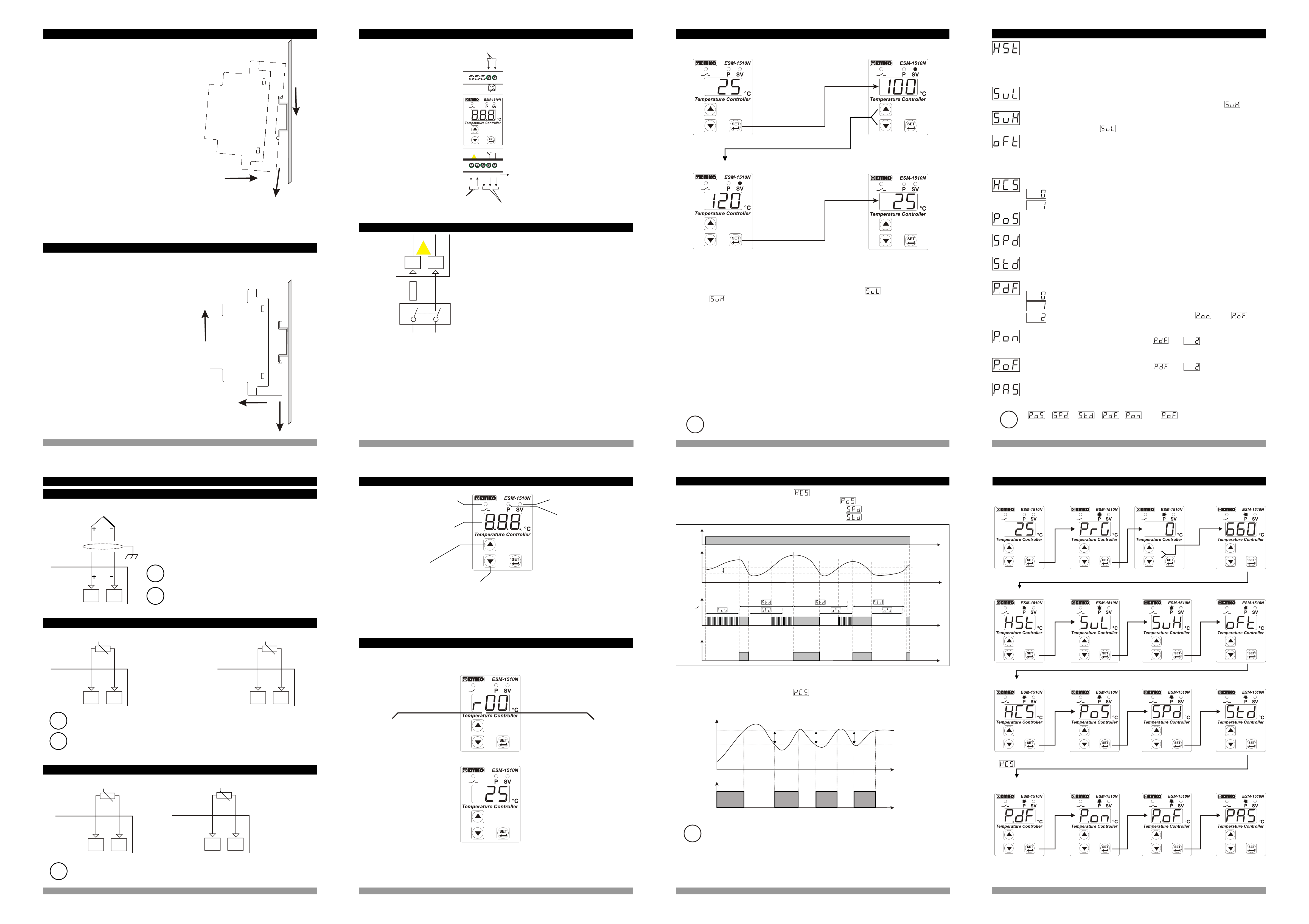
4.3 Program Parameters
Hysteresis Parameter for Output ( Default = 1 )
1 to 100 °C for TC Type Devices,
1 to 100 °C for PT-100 (-50°C, 400°C) and PT-1000 (-50°C, 400°C),
0.1 to 10.0 °C for PT-100 (-19.9°C, 99.9°C) and PT-1000 (-19.9°C, 99.9°C),
1 to 20 °C for PTC (-50°C, 150°C) and NTC (-50°C, 100°C),
0.1 to 10.0 °C for PTC (-19.9°C, 99.9°C) and NTC (-19.9°C, 99.9°C)
Minimum Set Value Parameter ( Default =Minimum value of device scale )
Set value can not be lower than this value. This parameter value can be adjusted
from minimum value of device scale to maximum set value parameter
Maximum Set Value Parameter ( Default = Maximum value of device scale )
Set value can not be greater than this value. This parameter value can be adjusted
from minimum set value to maximum value of the device scale
Process Offset Parameter ( Default = 0 )
-100 to 100 °C for TC Type Devices,
-100 to 100 °C for PT-100 (-50°C , 400°C) and PT-1000 (-50°C , 400°C),
-10.0 to 10.0 °C for PT-100 (-19.9°C, 99.9°C) and PT-1000 (-19.9°C, 99.9°C),
-20 to 20 °C for PTC (-50°C, 150°C) and NTC (-50°C, 100°C),
-10.0 to 10.0 °C for PTC (-19.9°C, 99.9°C) and NTC (-19.9°C, 99.9°C)
Operating Type Parameter ( Default = 0 )
Heating
Cooling
Switch On Delay After Power On Parameter ( Default = 0 )
When power is first applied to the device, this time delay must be expired for
activation of the compressor. It can be adjusted from 0 to 20 minutes
Compressor Stop/Start Time Delay Parameter ( Default =0 )
When compressor is inactive, this time delay must be expired for activation of the
compressor. It can be adjusted from 0 to 20 minutes.
Compressor Start/Start Time Delay Parameter ( Default =0 )
This time delay must be expired between two activation of the compressor.
It can be adjusted from 0 to 20 minutes.
Probe Defect Parameter ( Default = 0 )
Compressor is OFF in case of probe defect
Compressor is ON in case of probe defect
Compressor operates periodically according to and time
periods in case of probe defect.
Compressor is active during this time period in case of probe defect
( Default = 0 ) If Probe Defect Parameter is , then this parameter
can be observed. It can be adjusted from 0 to 99.
Compressor is inactive during this time period in case of probe defect
( Default = 0 ) If Probe Defect Parameter is , then this parameter
can be observed. It can be adjusted from 0 to 99.
Programming Mode Accessing Password ( Default =0 )
It is used for accessing to the programming mode. It can be adjusted from 0 to 999.
If it is selected 0, password is not entered for accessing to the parameters.
, , , , and parameters are observed if
i
Operating type is selected “ Cooling ”. If operating type is selected “ Heating ”
beginning of the parameters list is shown.
3.2 Temperature Sensor Input Connection
3.2.1 TC (Thermocouple) Connection
TC
ii
67
3.2.2 PTC and NTC Connection
ii
5
Connect the wires with the polarity as shown in
the figure left.
Always use compensation wire corresponding
to the thermocouple used. If present, the shield
must be connected to a proper ground.
Input resistance is greater than 10M W.
6
4. Front Panel Definition and Accessing to the Menus
Displays Temperature
Value,Temperature Set
Value and Parameters
Led indication of Output
is active (If blinks, Compressor
protection time is active)
Note-1
It is used to
increase the value
and access to the
parameter in
programming
mode.
Note-1: If increment or decrement button is pressed for 5 seconds continuously, increment and
decrement number become 10, if increment or decrement button is pressed for 10 seconds
continuously, increment and decrement number become 100.
Note-1
Decrement
Button
Led indication of SET value
changing mode
Led indication of
Programming Mode is active
It is used to enter to
the SET value
changing mode,
programming mode
and used as OK
button.
4.4 Working Graphics of ESM-1510N Temperature Controller
1-If Operating Type Parameter Value = 1 (Cooling),
Switch On Delay After Power On Parameter Value ³ 1 ,
Compressor Stop/Start Time Delay Parameter Value ³ 1 and
Compressor Start/Start Time Delay Parameter Value ³ 1;
Power
°C
SET
Output
Led
Hst
Time
Time
Time
9
4.5 Easy Access Diagram Of Programming Mode Parameters
Operation Screen
Hysteresis Parameter
Programming Mode
Entering Screen
5 sn
Minimum Set Value
Parameter
Password Entering
Screen
Enter Password
with increment
and decrement
buttons
Press SET/OK button for accessing parameters
Maximum Set Value
Parameter
Password Entering
Screen
Process Offset
Parameter
10
PTC
WHITERED
67
ii
ii
3.2.3 PT-100 and PT-1000 Connection
Input resistance is greater than 10M W.
Pay attention the cable colours of PTC probe while doing the PTC probe
connection.
PT-100
PT-1000
NTC
4.1 Observation of Software Revision on the Displays
When power is first applied to the temperature controller, software revision number is shown on
the displays.
Output
2-If Operating Type Parameter Value = 0 (Heating),
Time
Operating Type Parameter
Switch On Delay After
Power On Parameter
Compressor Stop/Start
Time Delay Parameter
Compressor Start/Start
Time Delay Parameter
67
Temperature
Value
“ r” ÞRevision
Software
revision
Number
SET
ON
HSt
HSt HSt
Time
If Operating Type Parameter Value
= 1 (Cooling)
Probe Defect
Parameter
Compressor is active
during this time period
In case of probe defect
Compressor is inactive
during this time period
In case of probe defect
Programming Mode
Accessing Password
OFF
Temperature Control Output
In ON/OFF control algorithm, temperature value is tried to keep equal to set
value by opening or closing the last control element. ON/OFF controlled system,
i
67
ii
Input resistance is greater than 10M W.
67
Operation Screen is shown
If there is an unexpected situation while opening the device, power off the
device and inform a qualified personnel.
temperature value oscillates continuously. Temperature value’s oscillation period or
amplitude around set value changes according to controlled system. For reducing
oscillation period of temperature value, a threshold zone is formed below or around
set value and this zone is named hysteresis. Action of control output is described with
figures above.
Time
c
7
8
11
12