
Изображения служат только для ознакомления,
см. техническую документацию
Тип
температурный контроллер
Additional Functionality
ON/OFF
Maximum Operating Temperature
+55°C
Все параметры
Все документы
1 шт.
на сумму 132 800 руб.
Плати частями
от 33 200 руб. × 4 платежа
Описание
The Eurotherm 3216 temperature controller has a supply voltage ranging from 85VAC to 264VAC. This standard controller has a width of 48mm and a height of 48mm and depth of 101mm (1/16 DIN) device.
Технические параметры
| Тип | температурный контроллер | |
| Additional Functionality | ON/OFF | |
| Control Type | ON/OFF | |
| IP Rating | IP65 | |
| Maximum Operating Temperature | +55°C | |
| Minimum Operating Temperature | 0°C | |
| Number of Outputs | 3 | |
| Output Type | Changeover Relay, Relay | |
| Range | Eurotherm 3216 | |
| Series | 3216 | |
| Size | 48×48(1/16 DIN)mm | |
| Supply Voltage | 85 → 264 V ac | |
| Вес, г | 276 |
Техническая документация
Сроки доставки
Доставка в регион Сальск
| ПВЗ СДЭК | ||
| ПВЗ 5Post | ||
| Курьер | 10 июля1 | 378 руб.2 |
| ПВЗ Почта России | 12 июля1 | 426 руб.2 |
Цена и наличие в магазинах
| Ростов-на-Дону, проспект Соколо́ва, 53/182 |
нет в наличии |
* УТОЧНЯЙТЕ ВОЗМОЖНОСТЬ, ЦЕНУ И СРОК ПОСТАВКИ, В СВЯЗИ С ОГРАНИЧЕНИЕМ ЭКСПОРТА ТОВАРОВ ИЗ СТРАН ЕС И ВЕЛИКОБРИТАНИИ
- Описание и тех. спецификация
- Характеристики
- Способы доставки
Eurotherm Temperature Controller
The Eurotherm 3216 temperature controller has a supply voltage ranging from 85VAC to 264VAC. This standard controller has a width of 48mm and a height of 48mm and depth of 101mm (1/16 DIN) device. It has up to 3 outputs where the first output is Logic I/O whereas the second and third outputs are relay. It has quick and easy commissioning. It has quick and easy commissioning. It has clear information about the process of scrolling and custom messages. The custom alarm messages facilitate easy understanding. It also has a provision for recipe selection from the operator interface. It is enabled with an internal timer and setpoint programming. There is an integral ammeter for instant alerts regarding heater faults. Additionally, it has a remote setpoint solution for multi-zone applications.
Features and Benefits
Analogue retransmission
Current monitoring
Custom alarm messages for easy understanding
Expert configuration via PC wizard with online help
Heater failure detection
Modbus SP retransmission
Multi-language support (English, German, French, Italian and Spanish)
Programmable with iTools configuration software when used with configuration clip
Recipe selection from operator interface
Safety Messaging via 4 digit starburst display for simple visual indication of the process status
Universal inputs are B, J, K, L, N, R, S, T, C, PT100, 0mV to 80mV, 0mA to 20mA, 4mA to 20mA
Applications
Heat treatment
Hot runner
Ovens & chillers
Plastics extrusion
Stress relieving
Thermal forming
Certifications
AMS2750D
BS EN61326
CE certified
cUL approved (file E57766)
DIN 3440 (3216 only) suitable for use in Nadcap
EN14597 TR
EN14597 TR
GOST-R
IP65 rated
Техническая спецификация
Model 3200 Series Data Sheet
3200 PID Temperature Controllers User Guide
User Manual — Eurotherm 3200 PID Temperature controllers
Дополнительная функциональность:
ON/OFF
Напряжение питания:
85 → 264 В перем. тока
Рабочая температура — максимальная:
+55°C
Рабочая температура — минимальная:
0°C
Размер:
48 x 48 (1/16 DIN)мм
Тип выхода:
Changeover Relay, Logic, Relay
| Самовывоз со склада поставщика в Екатеринбурге | Забираете сами или вызываете курьера |
| ТК Деловые Линии | от 500 руб |
| Курьером EMS Почта России | от 500 руб |
| Другой транспортной компанией | По согласованию |

Models 3216, 3208 and 3204
Process Controller
User Manual
Part No HA028651_15
Date December 2015

This page is intentionally blank

3200 Series User Manual
3200 Series PID Temperature Controllers
User Manual Part Number HA028651 Issue 15.0 December 15
Includes 3216, 3208, 32h8 and 3204 Controllers.
Contents
2. Installation and Basic Operation …………………………………………………………………………………………. 6
2.1 What Instrument Do I Have? ……………………………………………………………………………………………………………… 6
2.2 Unpacking Your Controller………………………………………………………………………………………………………………… 6
2.3 Dimensions …………………………………………………………………………………………………………………………………….. 6
2.4 Step 1: Installation ………………………………………………………………………………………………………………………….. 7
2.4.1 Panel Mounting the Controller ……………………………………………………………………………………………………………………………………………………. 7
2.4.2 Panel Cut Out Sizes ………………………………………………………………………………………………………………………………………………………………………. 7
2.4.3 Recommended minimum spacing of controllers ………………………………………………………………………………………………………………………. 7
2.4.4 To Remove the Controller from its Sleeve ………………………………………………………………………………………………………………………………… 7
2.5 Order Code …………………………………………………………………………………………………………………………………….. 8
3. Step 2: Wiring …………………………………………………………………………………………………………………. 9
3.1 Terminal Layout 3216 Controller ………………………………………………………………………………………………………… 9
3.2 Terminal Layout 32h8 Controllers……………………………………………………………………………………………………….. 10
3.3 Terminal Layout 3208 and 3204 Controllers ………………………………………………………………………………………….. 11
3.4 Wire Sizes ………………………………………………………………………………………………………………………………………. 12
3.5 Precautions …………………………………………………………………………………………………………………………………….. 12
3.6 Sensor Input (Measuring Input) ………………………………………………………………………………………………………….. 12
3.6.1 Thermocouple Input …………………………………………………………………………………………………………………………………………………………………….. 12
3.6.2 RTD Input ………………………………………………………………………………………………………………………………………………………………………………………. 12
3.6.3 Linear Input (mA or mV) ……………………………………………………………………………………………………………………………………………………………… 12
3.6.4 Two-Wire Transmitter Inputs ………………………………………………………………………………………………………………………………………………………. 12
3.7 Input/Output 1 & Output 2 ………………………………………………………………………………………………………………… 13
3.7.1 Relay Output (Form A, normally open) ……………………………………………………………………………………………………………………………………… 13
3.7.2 Logic (SSR drive) Output ……………………………………………………………………………………………………………………………………………………………… 13
3.7.3 DC Output …………………………………………………………………………………………………………………………………………………………………………………….. 13
3.7.4 Triac Output ………………………………………………………………………………………………………………………………………………………………………………….. 13
3.7.5 Logic Contact Closure Input (I/O 1 only) …………………………………………………………………………………………………………………………………… 13
3.8 Remote Setpoint Input ……………………………………………………………………………………………………………………… 13
3.9 Output 3 ………………………………………………………………………………………………………………………………………… 13
3.10 Summary of DC Outputs …………………………………………………………………………………………………………………… 13
3.11 Output 4 (AA Relay) …………………………………………………………………………………………………………………………. 14
3.12 General Note About Relays and Inductive Loads …………………………………………………………………………………… 14
3.13 Digital Inputs A & B ………………………………………………………………………………………………………………………….. 14
3.14 Current Transformer ………………………………………………………………………………………………………………………… 14
3.15 Transmitter Power Supply …………………………………………………………………………………………………………………. 14
3.16 Digital Communications ……………………………………………………………………………………………………………………. 15
3.17 Controller Power Supply …………………………………………………………………………………………………………………… 16
3.18 Example Heat/Cool Wiring Diagram ……………………………………………………………………………………………………. 16
3.18.1 Example CT Wiring Diagram …………………………………………………………………………………………………………………………………………………… 16
4. Safety and EMC Information ………………………………………………………………………………………………. 17
4.1 Installation Safety Requirements ………………………………………………………………………………………………………… 17
5. Switch On ………………………………………………………………………………………………………………………… 19
5.1 New Controller ……………………………………………………………………………………………………………………………….. 19
5.1.1 Quick Start Code ………………………………………………………………………………………………………………………………………………………………………….. 19
5.2 To Re-Enter Quick Code mode ……………………………………………………………………………………………………………. 20
5.3 Pre-Configured Controller or Subsequent Starts ……………………………………………………………………………………. 20
5.4 Front Panel Layout …………………………………………………………………………………………………………………………… 21
5.4.1 To Set The Target Temperature. …………………………………………………………………………………………………………………………………………………. 21
5.4.2 Alarms ……………………………………………………………………………………………………………………………………………………………………………………………. 21
5.4.3 Alarm Indication …………………………………………………………………………………………………………………………………………………………………………… 21
5.4.4 Auto, Manual and Off Mode ……………………………………………………………………………………………………………………………………………………….. 22
5.4.5 To Select Auto, Manual or Off Mode …………………………………………………………………………………………………………………………………………. 22
5.4.6 Level 1 Operator Parameters ………………………………………………………………………………………………………………………………………………………. 23
1 Part No HA028651 Issue 15.0 CN33995 Dec-15

User Manual 3200 Series
2 Part No HA028651 Issue 15.0 Dec-15
6. Operator Level 2 ……………………………………………………………………………………………………………….. 23
6.1 To Enter Level 2 ………………………………………………………………………………………………………………………………. 23
6.2 To Return to Level 1 …………………………………………………………………………………………………………………………. 23
6.3 Level 2 Parameters …………………………………………………………………………………………………………………………… 23
6.4 Timer Operation………………………………………………………………………………………………………………………………. 27
6.5 Dwell Timer ……………………………………………………………………………………………………………………………………. 27
6.6 Delayed Timer …………………………………………………………………………………………………………………………………. 28
6.7 Soft Start Timer ………………………………………………………………………………………………………………………………. 29
6.8 To Operate a Timer ………………………………………………………………………………………………………………………….. 29
6.9 Programmer ……………………………………………………………………………………………………………………………………. 30
6.9.1 To Set Up a Temperature Profile ……………………………………………………………………………………………………………………………………………….. 31
6.9.2 Programmer Servo Mode and Power Cycling ……………………………………………………………………………………………………………………………. 32
6.9.3 To Operate the Programmer ………………………………………………………………………………………………………………………………………………………. 32
7. Access to Further Parameters ……………………………………………………………………………………………… 33
7.1 Parameter Levels ……………………………………………………………………………………………………………………………… 33
7.1.1 Level 3 …………………………………………………………………………………………………………………………………………………………………………………………… 33
7.1.2 Configuration Level ……………………………………………………………………………………………………………………………………………………………………… 33
7.1.3 To Select Access Level 3 or Configuration Level ………………………………………………………………………………………………………………………. 34
7.2 Parameter lists ………………………………………………………………………………………………………………………………… 35
7.2.1 To Choose Parameter List Headers …………………………………………………………………………………………………………………………………………….. 35
7.2.2 To Locate a Parameter ………………………………………………………………………………………………………………………………………………………………… 35
7.2.3 How Parameters are Displayed …………………………………………………………………………………………………………………………………………………… 35
7.2.4 To Change a Parameter Value ……………………………………………………………………………………………………………………………………………………. 35
7.2.5 To Return to the HOME Display …………………………………………………………………………………………………………………………………………………. 35
7.2.6 Time Out ………………………………………………………………………………………………………………………………………………………………………………………. 35
7.3 Navigation Diagram …………………………………………………………………………………………………………………………. 36
7.4 Access Parameters …………………………………………………………………………………………………………………………… 37
8. Controller Block Diagram …………………………………………………………………………………………………… 39
9. Temperature (or Process) Input…………………………………………………………………………………………… 40
9.1 Process Input Parameters ………………………………………………………………………………………………………………….. 40
9.1.1 Input Types and Ranges ………………………………………………………………………………………………………………………………………………………………. 41
9.1.2 Operation of Sensor Break …………………………………………………………………………………………………………………………………………………………. 42
9.2 PV Offset ……………………………………………………………………………………………………………………………………….. 43
9.2.1 Example: To Apply an Offset:- …………………………………………………………………………………………………………………………………………………… 43
9.3 PV Input Scaling ………………………………………………………………………………………………………………………………. 43
9.3.1 Example: To Scale a Linear Input ………………………………………………………………………………………………………………………………………………. 43
10. Input/Output ……………………………………………………………………………………………………………………. 44
10.1 Input/Output Parameters ………………………………………………………………………………………………………………….. 45
10.1.1 Input/Output 1 List (IO-1)…………………………………………………………………………………………………………………………………………………….. 45
10.1.2 Remote Digital Setpoint Select and Remote Fail…………………………………………………………………………………………………………………. 47
10.1.3 Sense ……………………………………………………………………………………………………………………………………………………………………………………….. 47
10.1.4 Source ……………………………………………………………………………………………………………………………………………………………………………………… 47
10.1.5 Power Fail………………………………………………………………………………………………………………………………………………………………………………… 47
10.1.6 Example: To Configure IO-1 Relay to Operate on Alarms 1 and 2:- …………………………………………………………………………………. 47
10.1.7 Output List 2 (OP-2) ……………………………………………………………………………………………………………………………………………………………… 48
10.1.8 Output List 3 (OP-3) ……………………………………………………………………………………………………………………………………………………………… 49
10.1.9 AA Relay (AA) (Output 4) …………………………………………………………………………………………………………………………………………………….. 50
10.1.10 Digital Input Parameters ………………………………………………………………………………………………………………………………………………………… 51
10.2 Current Transformer Input Parameters ……………………………………………………………………………………………….. 52
10.2.1 Analogue Representation of Current Alarms ………………………………………………………………………………………………………………………. 52
11. Setpoint Generator ……………………………………………………………………………………………………………. 53
11.1 Setpoint Parameters …………………………………………………………………………………………………………………………. 53
11.2 Example: To Adjust Setpoint Rate Limit………………………………………………………………………………………………. 54
12. Control ……………………………………………………………………………………………………………………………. 55
12.1 Types of Control ……………………………………………………………………………………………………………………………… 55
12.1.1 On/Off Control ……………………………………………………………………………………………………………………………………………………………………….. 55
12.1.2 PID Control ……………………………………………………………………………………………………………………………………………………………………………… 55
12.1.3 Motorised Valve Control ……………………………………………………………………………………………………………………………………………………….. 56
12.1.3.1 Motorised Valve Control in Manual mode …………………………………………………………………………………………………………………………… 56
12.2 Control Parameters ………………………………………………………………………………………………………………………….. 57
12.2.1 Proportional Band ‘PB’ …………………………………………………………………………………………………………………………………………………………… 59
12.2.2 Integral Term ‘TI’ ……………………………………………………………………………………………………………………………………………………………………. 59
12.2.3 Derivative Term ‘TD’ ………………………………………………………………………………………………………………………………………………………………. 60

3200 Series User Manual
Part No HA028651 Issue 15.0 Dec-15 3
12.2.4 Relative Cool Gain ‘R2G’ …………………………………………………………………………………………………………………………………………………………. 60
12.2.5 High and Low Cutback ……………………………………………………………………………………………………………………………………………………………. 61
12.2.6 Manual Reset …………………………………………………………………………………………………………………………………………………………………………… 61
12.2.7 Control Action …………………………………………………………………………………………………………………………………………………………………………. 61
12.2.8 Loop Break ………………………………………………………………………………………………………………………………………………………………………………. 61
12.2.9 Cooling Algorithm …………………………………………………………………………………………………………………………………………………………………… 61
12.3 Tuning……………………………………………………………………………………………………………………………………………. 62
12.3.1 Loop Response ………………………………………………………………………………………………………………………………………………………………………… 62
12.3.2 Initial Settings ………………………………………………………………………………………………………………………………………………………………………….. 62
12.3.3 Automatic Tuning ……………………………………………………………………………………………………………………………………………………………………. 64
12.3.4 To Start Autotune …………………………………………………………………………………………………………………………………………………………………… 64
12.3.5 Autotune from Below SP – Heat/Cool ………………………………………………………………………………………………………………………………….. 65
12.3.6 Autotune From Below SP – Heat Only ………………………………………………………………………………………………………………………………….. 66
12.3.7 Autotune at Setpoint – Heat/Cool ………………………………………………………………………………………………………………………………………… 67
12.3.8 Manual Tuning ………………………………………………………………………………………………………………………………………………………………………… 68
12.3.9 Manually Setting Relative Cool Gain ……………………………………………………………………………………………………………………………………… 68
12.3.10 Manually Setting the Cutback Values ……………………………………………………………………………………………………………………………………. 69
12.4 Auto-tune Configures R2G …………………………………………………………………………………………………………………. 70
12.5 Example: To Configure Heating and Cooling ……………………………………………………………………………………….. 71
12.5.1 Effect of Control Action, Hysteresis and Deadband …………………………………………………………………………………………………………….. 72
13. Alarms …………………………………………………………………………………………………………………………….. 73
13.1 Types of Alarm ………………………………………………………………………………………………………………………………… 73
13.1.1 Alarm Relay Output ………………………………………………………………………………………………………………………………………………………………… 75
13.1.2 Alarm Indication ……………………………………………………………………………………………………………………………………………………………………… 75
13.1.3 To Acknowledge An Alarm …………………………………………………………………………………………………………………………………………………….. 75
13.2 Behaviour of Alarms After a Power Cycle …………………………………………………………………………………………….. 76
13.2.1 Example 1 ………………………………………………………………………………………………………………………………………………………………………………… 76
13.2.2 Example 2 ………………………………………………………………………………………………………………………………………………………………………………… 76
13.2.3 Example 3 ………………………………………………………………………………………………………………………………………………………………………………… 76
13.3 Alarm Parameters ……………………………………………………………………………………………………………………………. 77
13.3.1 Example: To Configure Alarm 1 ……………………………………………………………………………………………………………………………………………. 78
13.4 Diagnostic Alarms ……………………………………………………………………………………………………………………………. 79
13.4.1 Out of Range Indication …………………………………………………………………………………………………………………………………………………………. 79
14. Timer/Programmer ……………………………………………………………………………………………………………. 80
14.1 Timer Configuration Parameters ………………………………………………………………………………………………………… 80
14.2 Programmer ……………………………………………………………………………………………………………………………………. 82
14.2.1 Threshold …………………………………………………………………………………………………………………………………………………………………………………. 82
14.2.2 Run/End Digital Outputs…………………………………………………………………………………………………………………………………………………………. 83
14.2.3 Event Output During a Segment ……………………………………………………………………………………………………………………………………………. 83
14.2.4 To Configure the Programmer ………………………………………………………………………………………………………………………………………………. 84
14.3 Example: To Configure a Dwell Timer as a Simple Two Step Programmer ………………………………………………….. 85
15. Recipe …………………………………………………………………………………………………………………………….. 88
15.1 To Save Values in a Recipe ………………………………………………………………………………………………………………… 88
15.2 To Save Values in a Second Recipe ……………………………………………………………………………………………………… 88
15.3 To Select a Recipe to Run …………………………………………………………………………………………………………………. 89
15.3.1 List of Default Recipe Parameters: ………………………………………………………………………………………………………………………………………… 89
16. Digital Communications …………………………………………………………………………………………………….. 90
16.1 Digital Communications Wiring ………………………………………………………………………………………………………….. 90
16.1.1 EIA232 ………………………………………………………………………………………………………………………………………………………………………………………. 90
16.1.2 EIA485 (2-wire)………………………………………………………………………………………………………………………………………………………………………… 90
16.1.3 Wiring EIA422 or 4-wire EIA485 …………………………………………………………………………………………………………………………………………….. 90
16.2 Digital Communications Parameters ……………………………………………………………………………………………………. 91
16.2.1 Broadcast Communications ……………………………………………………………………………………………………………………………………………………. 92
16.2.2 Broadcast Master Communications ………………………………………………………………………………………………………………………………………. 92
16.2.3 Wiring Connections ………………………………………………………………………………………………………………………………………………………………… 92
16.3 EEPROM Write Cycles ……………………………………………………………………………………………………………………….. 93
16.4 Example: To Set Up Instrument Address ………………………………………………………………………………………………. 94
16.5 DATA ENCODING …………………………………………………………………………………………………………………………….. 94
16.6 Parameter Modbus Addresses ……………………………………………………………………………………………………………. 95
17. Calibration ………………………………………………………………………………………………………………………. 105
17.1 To Check Input Calibration ……………………………………………………………………………………………………………….. 105
17.1.1 Precautions ………………………………………………………………………………………………………………………………………………………………………………. 105
17.1.2 To Check mV Input Calibration ……………………………………………………………………………………………………………………………………………… 105

User Manual 3200 Series
4 Part No HA028651 Issue 15.0 Dec-15
17.1.3 To Check Thermocouple Input Calibration ………………………………………………………………………………………………………………………….. 105
17.1.4 To Check RTD Input Calibration ……………………………………………………………………………………………………………………………………………. 106
17.2 Offsets …………………………………………………………………………………………………………………………………………… 106
17.2.1 Two Point Offset …………………………………………………………………………………………………………………………………………………………………….. 106
17.2.2 To Apply a Two Point Offset …………………………………………………………………………………………………………………………………………………. 107
17.2.3 To Remove the Two Point Offset ………………………………………………………………………………………………………………………………………….. 107
17.3 Input Calibration ……………………………………………………………………………………………………………………………… 108
17.3.1 To Calibrate mV Input ……………………………………………………………………………………………………………………………………………………………. 108
17.3.2 To Calibrate Thermocouple Input ………………………………………………………………………………………………………………………………………… 109
17.3.3 To Calibrate RTD Input ………………………………………………………………………………………………………………………………………………………….. 110
17.3.4 To Calibrate mA Outputs ………………………………………………………………………………………………………………………………………………………. 111
17.3.5 To Calibrate Remote Setpoint Input …………………………………………………………………………………………………………………………………….. 112
17.3.6 CT Calibration …………………………………………………………………………………………………………………………………………………………………………. 113
17.3.7 To Return to Factory Calibration ………………………………………………………………………………………………………………………………………….. 113
17.4 Calibration Parameters …………………………………………………………………………………………………………………….. 114
18. Configuration Using iTools …………………………………………………………………………………………………. 115
18.1 Loading an IDM ……………………………………………………………………………………………………………………………….. 115
18.2 Connecting a PC to the Controller ……………………………………………………………………………………………………… 115
18.2.1 Using the H Communications Port ……………………………………………………………………………………………………………………………………….. 115
18.2.2 Configuration Clip ………………………………………………………………………………………………………………………………………………………………….. 115
18.3 Starting iTools …………………………………………………………………………………………………………………………………. 116
18.4 Starting the Wizard ………………………………………………………………………………………………………………………….. 117
18.5 To configure the Input ……………………………………………………………………………………………………………………… 118
18.5.1 Example 1 — Using the Wizard ……………………………………………………………………………………………………………………………………………….. 118
18.5.2 Example 2 – Using the Browser View …………………………………………………………………………………………………………………………………… 118
18.6 To Configure Alarms ………………………………………………………………………………………………………………………… 119
18.6.1 Example 1: Using the Wizard………………………………………………………………………………………………………………………………………………… 119
18.6.2 Example 2: Using the Browser View ……………………………………………………………………………………………………………………………………… 119
18.7 To Customise Messages …………………………………………………………………………………………………………………….. 120
18.7.1 Example 1: Using the Wizard………………………………………………………………………………………………………………………………………………… 120
18.7.2 Example 2: Using the Browser View …………………………………………………………………………………………………………………………………….. 121
18.7.3 Example 3: Inverted Status Word ………………………………………………………………………………………………………………………………………… 122
18.7.4 Example 4: Display the message ‘OUT OF CONTROL’ if both Alarm 1 and Alarm 2 are active. ……………………………………. 123
18.8 To Promote Parameters…………………………………………………………………………………………………………………….. 124
18.8.1 Example 1: Using the Wizard………………………………………………………………………………………………………………………………………………… 124
18.8.2 Example 2: Using the Browser view …………………………………………………………………………………………………………………………………….. 125
18.9 To Load A Special Linearisation Table …………………………………………………………………………………………………. 126
18.9.1 Example: Using the Browser view ………………………………………………………………………………………………………………………………………… 126
18.10 To Set up Recipes ………………………………………………………………………………………………………………………… 127
18.10.1 Example 1: Using the Browser view …………………………………………………………………………………………………………………………………….. 127
18.10.2 Example 2: Using the Wizard………………………………………………………………………………………………………………………………………………… 128
18.10.2.1 Recipe Definition ………………………………………………………………………………………………………………………………………………………………. 128
18.10.2.2 Editing Recipe Values ……………………………………………………………………………………………………………………………………………………….. 129
18.10.2.3 Recipe Names ……………………………………………………………………………………………………………………………………………………………………. 129
18.11 Summary ……………………………………………………………………………………………………………………………………. 130
18.11.1 Example 1: Using the Wizard………………………………………………………………………………………………………………………………………………… 130
18.11.2 Example 2: Using the browser view. ……………………………………………………………………………………………………………………………………. 130
18.12 Cloning ………………………………………………………………………………………………………………………………………. 131
18.12.1 Save to File ……………………………………………………………………………………………………………………………………………………………………………… 131
18.12.2 To Clone a New Controller ……………………………………………………………………………………………………………………………………………………. 131
19. Appendix A TECHNICAL SPECIFICATION ……………………………………………………………………………… 132
20. Parameter Index ……………………………………………………………………………………………………………….. 134
21. Index ……………………………………………………………………………………………………………………………….. 136

3200 Series User Manual
Part No HA028651 Issue 15.0 Dec-15 5
Issue Status of this Manual
Issue 5 of this Handbook applies to software versions 2.09 and above for PID controller and 2.29 and above for Valve
Position controllers and includes:-
• Remote Setpoint Input Option RCL
• Programmer Cycles
• Triac output
• EIA422 4-wire Digital Communications, Option 6XX available in 3216 only
It also applies to firmware versions 2.11 and includes new parameters:Inverted status word, section 17.7.3.
Rate of change alarms, section 12.3.
Setpoint retransmission limits, section 10.1.
Input filter, section 8.1.
Note:The 3116 controller is no longer available. Details may be found in issue 4 of this manual.
Issue 6 includes parameter ‘AT.R2G’, section 11.4.
Issue 7 corrects range limits in section 8.1.1. Change to definition of LOC.T. in section 10.1. Correct description of
enumerations for parameter IM section 15.6.
Issue 8 includes the following changes:
The description of the Programmer in sections 5.9 and 13.2.
A more detailed description of loop tuning.
Updates to Appendix A, Technical Specification.
Issue 9 includes the following changes:
Clarification of order codes for isolated and non- isolated outputs in appropriate sections
Add Tune Hi and Tune Lo limit parameters to the Control table in section 11.2.
Issue 10 applies to software versions 2.13 for PID controllers and 2.32 for Valve Position controllers and includes the
following changes:
Warning added to section 15.1.3. ref number of writes to EEPROM.
Notes column in section 13.2.4. — changes to the resolution of Dwell units and Ramp Rate refers to section 10.1.
Sections 2.8 and 4.4.3. clarify remote setpoint operation.
Issue 11 corrects instruction 3) in section 11.4; adds Certificate of Conformity; adds a new section 15.3 EEPROM Write
Cycles; update DIN3440 to EN14597TR in the Approvals section 18.
Issue 12 corrects the note (2) in section 2.1 to EIA422 and deletes the corresponding statement in section 2.14. Contact
resistance ratings changed in section 2.13.
Issue 13 changes panel sealing ratings in the Specification section. Remove Declaration of Conformity.
Issue 14 update to Safety and EMC section. Add NEMA12 to Specification.
Issue 15 corrects the terminal numbering in section 16.3.5. Timer Status description updated to be the same as the
iTools Help and improves the descrption of the timer when used as a programmer.

User Manual 3200 Series
6 Part No HA028651 Issue 15.0 Dec-15
1. Installation and Basic Operation
1.1 What Instrument Do I Have?
Thank you for choosing this 3200 series Temperature
Controller/Programmer.
The 3200 series provide precise temperature control of
industrial processes and is available in three standard
DIN sizes:-
• 1/16 DIN Model Number 3216
• 1/8 DIN Model Number 3208
• 1/8 DIN Horizontal Model Number 32h8
• 1/4 DIN Model Number 3204
A universal input accepts various thermocouples, RTDs or
process inputs. Up to three (3216) or four (3208, 32h8
and 3204) outputs can be configured for control, alarm
or re-transmission purposes. Digital communications and
a current transformer input are available as options.
The controller may have been ordered to a hardware
code only or pre-configured using an optional ‘Quick
Start’ code.
The label fitted to the side of the sleeve shows the
ordering code that the controller was supplied to.
The last two sets of five digits show the Quick Start Code.
If the Quick Start Code shows *****/***** the controller
was supplied with default parameters and will need to be
configured when it is first switched on.
This Manual takes you through all aspects of installation,
wiring, configuration and use of the controller.
1.2 Unpacking Your Controller
The controller is supplied with:-
• Sleeve (with the controller fitted in the sleeve)
• Two panel retaining clips and IP65 sealing gasket
mounted on the sleeve
• Component packet containing a snubber for each
relay output (see section 2.12) and a 2.49Ω resistor
for current inputs (see section 2.6)
• Installation sheet Part Number HA029714
1.3 Dimensions
General views of the controllers are shown below
together with overall dimensions.
3216
Front View
48mm
48mm
(1.89in)
Top View
3208, 32h8 and 3204
3208
96mm
(3.78in)
48mm
Front Views
Side View
1.25mm
(0.5in)
Latching
ears
IP65 Sealing Gasket
Latching
ears
48mm
Latching
ears
Side View
Panel retaining clips
90mm (3.54in)
Panel retaining clip
3204
96mm (3.78in)
32h8
90mm (3.54in)
Label showing
Order Code
Serial Number
including date of
manufacture
IP65 Sealing Gasket

3200 Series User Manual
Part No HA028651 Issue 15.0 Dec-15 7
1.4 Step 1: Installation
This instrument is intended for permanent installation,
for indoor use only, and enclosed in an electrical panel
Select a location which is subject to minimum vibrations
the ambient temperature is within 0 and 55
o
131
F) and humidity 5 to 95% RH non condensing.
The instrument can be mounted on a panel up to 15mm
thick.
To ensure IP65 front protection, mount on a nontextured surface using the gasket provided.
Please read the safety information in section 3 before
proceeding. The EMC Booklet part number HA025464
gives further installation information.
1.4.1 Panel Mounting the Controller
1. Prepare a cut-out in the mounting panel to the size
shown. If a number of controllers are to be mounted
in the same panel observe the minimum spacing
shown.
2. Fit the panel sealing gasket behind the front bezel of
the controller
3. Insert the controller through the cut-out
4. Spring the panel retaining clips into place. Secure
the controller in position by holding it level and
pushing both retaining clips forward.
5. Peel off the protective cover from the display.
o
C (32 —
1.4.2 Panel Cut Out Sizes
Model 3216
45 mm
— 0.0 + 0.6
1.77 in
-0.00, +0.02
Model 32h8
— 0.0 + 0.6
45 mm
1.77 in -0.00, +0.02
92 mm — 0.0 + 0.8
0.00, +0.03
3.62 in —
92 mm
— 0.0 + 0.8
3.62 in
0.00, +0.03
—
1.4.3 Recommended minimum spacing of
controllers
Applies to all models.
10mm (0.4 in)
38mm (1.5 in)
1.4.4 To Remove the Controller from its
Sleeve
The controller can be unplugged from its sleeve by
easing the latching ears outwards and pulling it forward
out of the sleeve. When plugging it back into its sleeve,
ensure that the latching ears click back into place to
maintain the IP65 sealing

User Manual 3200 Series
8 Part No HA028651 Issue 15.0 Dec-15
1.5 Order Code
1 2 3 4 5 6 7 8 9 10 11 12 13 14
1. Model No.
1/16 DIN size 3216
1/8 DIN size vertical 3208
1/8 DIN horizontal 32h8
1/4 DIN size 3204
2. Function
Controller CC
Programmer CP
valve controller VC
Valve programmer VP
3. Power Supply
24Vac/dc VL
100–230Vac VH
4. Output 1 & 2 3216
OP1 OP2
L X X X
L R X X
R R X X
L L X X
L D X X
D D X X
D R X X
R C X X
L C X X
D C X X
Not available with low voltage
supply option.
L T X X
T T X X
L = Logic
R = Relay
T = Triac
D = 0-20mA non-isolated
C = 0-20mA isolated
4. Outputs 1, 2 and 3 3208/H8/04
OP1 OP2 OP3
L R R X
R R R X
L L R X
L R D X
R R D X
D D D X
L L D X
L D D X
D R D X
Not available with low voltage
supply option.
L T R X
T T R X
L T D X
T D D X
T T D X
L = Logic
R = Relay
T = Triac
D = 0-20mA non-isolated outputs 1
and 2
D = 0-20mA isolated output 3
5. AA Relay (OP4)
Disabled X
Relay (Form C) R
6. Options
Not fitted XXX
EIA485 & Digital input A 4XL*
EIA232 & Digital input A 2XL*
EIA485, CT & Dig in A 4CL
EIA232, CT & Dig in A 2CL
Digital input A XXL*
CT & Digital input A XCL
Remote SP and Logic IP RCL
4-wire EIA485 (EIA422)
6XX
Comms (3216 only)
* 3216 only
7. Fascia colour/type
Green G
Silver S
Wash down fascia
W
(not 32h8/04)
8/9 Product/Manual Language
English ENG
French FRA
German GER
Italian ITA
Spanish SPA
10. Extended Warranty
Standard XXXXX
Extended WL005
11. Certificates
XXXXX None
Cert of conformity CERT1
Factory calibration CERT2
12. Custom Label
None XXXXX
13. Specials Number
None XXXXXX
250Ω ; 0-5Vdc OP RES250
500Ω ; 0-10Vdc OP RES500
3200 Series User Manual
Part No HA028651 Issue 15.0 Dec-15 9
2. Step 2: Wiring
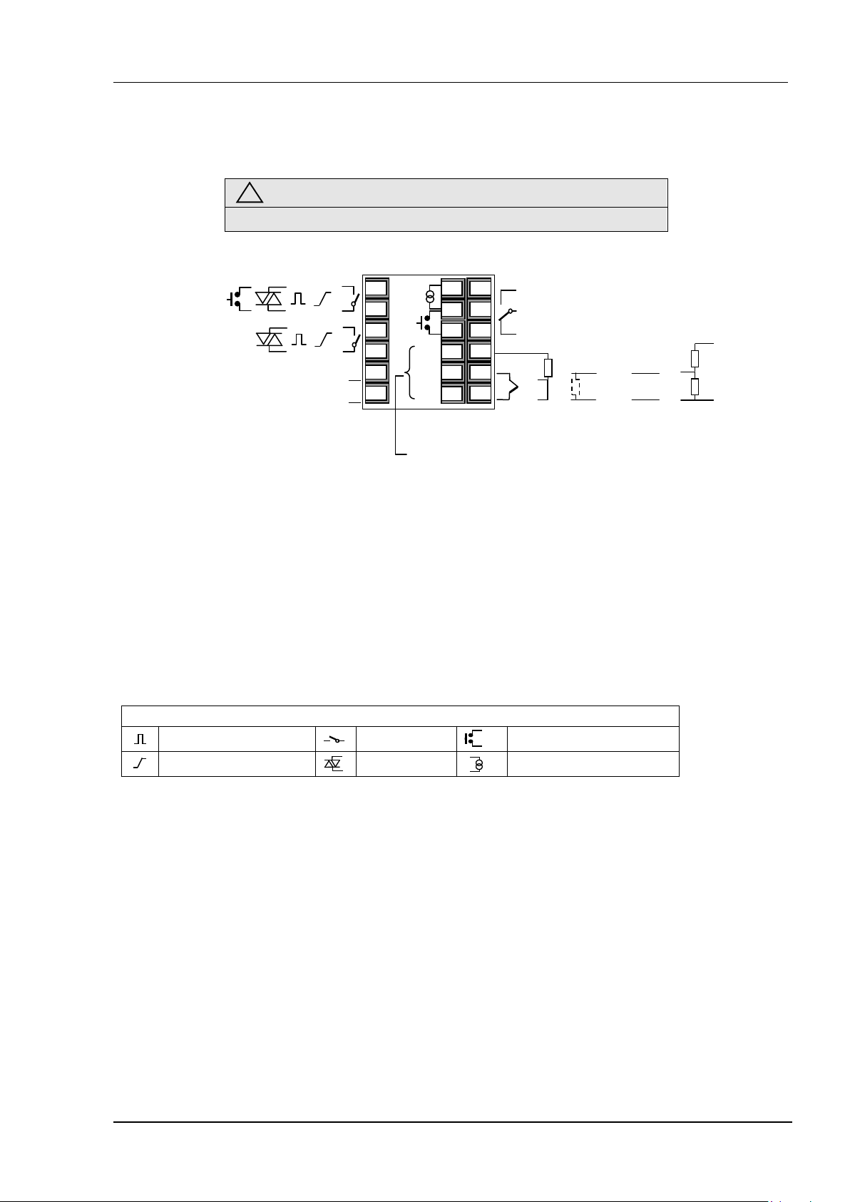
2.1 Terminal Layout 3216 Controller
(1)
Line Supply 100 to 230Vac +/-15%
48 — 62Hz
OR
Low Voltage Supply 24Vac/dc
24Vac -15%, +10%. 48 – 62Hz
24Vdc -15%, +20%
(1) If I/O 1 is fitted with a 0-20mA analogue output then this output is always non-isolated (order code D). Output 2 may
be fitted with an isolated 0-20mA output, order code C, or a non-isolated 0-20mA output, order code D.
(2) Option 6XX – EIA422 digital communications uses terminals C to HF. This means that the Current Transformer and
Digital Input A are not available if this option is fitted.
Logic (SSR drive) output
Ensure that you have the correct supply for your controller
Check order code of the instrument supplied
+ +
— —
+ +
— —
1A
1B
2A
2B
L
N
COM
A(+)
B(-)
CT
C
LA
HD
HE
HF
AA
AB
AC
VI
V+
V-
Output 4 (AA Relay)
+
T/C
Digital Communications
EIA232, EIA485, or EIA422
(2)
Or
Remote Setpoint IP
See section 2.8
Key to symbols used in the wiring diagrams
Relay output
Contact input
+ +
Input
—
Potential divider
module
Part No SUB21/IV10
mA analogue output
Triac output
Current transformer input

User Manual 3200 Series
10 Part No HA028651 Issue 15.0 Dec-15
2.2 Terminal Layout 32h8 Controllers
48 — 62Hz
OR
Low Voltage Supply 24Vac/dc
24Vac -15%, +10%. 48 – 62Hz
24Vdc -15%, +20%
module
Part No SUB21/IV10
—
Key to symbols used in the wiring diagrams
Logic (SSR drive) output
Ensure that you have the correct supply for your controller
Check order code of the instrument supplied
+
Relay output
2
Output 1
+
—
3D 3C 3B 3A LC LB 2B 2A 1B 1A
N L
3
— +
C NO
in B
— + — +
— + — +
C NO C NO Line Supply 100 to 230Vac +/-15%
32h8 Controller
V- V+ VI LA C CT HF HE HD AC AB AA
— +
B(-) A(+) COM
Digital Comms
+ —
Dig in A
Sensor Input
Or
Remote Setpoint
Input
CT input
See section 2.8
Contact input
AA Relay
(OP4)
mA analogue output
Triac output
Current transformer input

3200 Series User Manual
Part No HA028651 Issue 15.0 Dec-15 11
Current transformer input
2.3 Terminal Layout 3208 and 3204 Controllers
(1)
(1)
Line Supply 100 to 230Vac +/-15%
48 — 62Hz
OR
Low Voltage Supply 24Vac/dc
24Vac -15%, +10%. 48 – 62Hz
24Vdc -15%, +20%
(1) If I/0 1 or OP2 are fitted with a 0-20mA analogue output then these outputs are always non-isolated. If OP 2 is
fitted with a 0-20mA analogue output this output is isolated 240Vac. The order code D applies to isolated or
non-isolated outputs in 3208, 32h8 and 3204 instruments.
Logic (SSR drive) output
Ensure that you have the correct supply for your controller
Check order code of the instrument supplied
T/C
COM
A(+)
B(-)
Output 4 (AA Relay)
Digital Communications
EIA232 or EIA485
Or
Remote Setpoint Input See section 2.8
CT input
Digital input A
PV Input
+
+ +
— —
+ +
— —
+
—
24V
—
1B
2A
2B
LB
LC
3B
3C
3D
AB
AC
HD
HE
HF
C
LA
VI
L
N
V+
V-
Key to symbols used in the wiring diagrams
Relay output
Contact input
+
Input
Potential divider
module
Part No
SUB21/IV10

User Manual 3200 Series
12 Part No HA028651 Issue 15.0 Dec-15
2.4 Wire Sizes
Using internal 24V power supply (3208, 32h8 and 3204 only)
The screw terminals accept wire sizes from 0.5 to 1.5 mm
(16 to 22AWG). Hinged covers prevent hands or metal
making accidental contact with live wires. The rear
terminal screws should be tightened to 0.4Nm (3.5lb in).
2.5 Precautions
• Do not run input wires together with power cables
• When shielded cable is used, it should be grounded
at one point only
• Any external components (such as zener barriers,
etc) connected between sensor and input terminals
may cause errors in measurement due to excessive
and/or un-balanced line resistance or possible
leakage currents
• Not isolated from the logic outputs & digital inputs
• Pay attention to line resistance; a high line resistance
may cause measurement errors
2.6 Sensor Input (Measuring Input)
2.6.1 Thermocouple Input
+
Positive
—
Negative
V-
• Use the correct compensating cable preferably
shielded
2.6.2 RTD Input
PRT
V+
PRT
V-
Lead compensation
• The resistance of the three wires must be the same.
The line resistance may cause errors if it is greater
than 22Ω
2.6.3 Linear Input (mA or mV)
V-
+
mA / mV input
—
• If shielded cable is used it should be grounded in
one place only as shown
• For a mA input connect the 2.49Ω burden resistor
supplied between the V+ and V- terminals as shown
• For a 0-10Vdc input an external input adapter is
required (not supplied). Part number: SUB21/IV10
+
806Ω
+
0-10V
Input
Sensor break alarm does not operate with this adaptor
fitted.
2.6.4 Two-Wire Transmitter Inputs
+
—
V-
+
3D
—
Using external power supply
+
—
V-
—
supply
+
+
+
Transmitter
Transmitter

3200 Series User Manual
Part No HA028651 Issue 15.0 Dec-15 13
2.7 Input/Output 1 & Output 2
These outputs can be logic (SSR drive), or relay, or mA
dc. In addition the logic output 1 can be used as a
contact closure input.
For input/output functions, see Quick Start Code in
section 4.1.1.
2.7.1 Relay Output (Form A, normally open)
• Isolated output 240Vac CAT II
• Contact rating: 2A 264Vac
1B
2B
2.7.2 Logic (SSR drive) Output
1B
2B
• The output switching rate must be set to prevent
damage to the output device in use. See
parameter 1.PLS or 2.PLS in section 5.3.
2.7.3 DC Output
1B
• Order code C (OP2 only) isolated 240Vac
• Order code D not isolated from the sensor input
• Software configurable: 0-20mA or 4-20mA.
• Max load resistance: 500Ω
• Calibration accuracy: +(<1% of reading + <100µA)
2.7.4 Triac Output
• Isolated output 240Vac CATII
1(2)B
• Rating: 0.75A rms, 30 to 264Vac resistive
2.7.5 Logic Contact Closure Input (I/O 1
only)
• Not isolated from the sensor input
• Switching: 12Vdc at 40mA max
1B
• Contact open > 500Ω. Contact closed <
150Ω
resistive
• Not isolated from the sensor
input
• Output ON state: 12Vdc at
40mA max
• Output OFF state: <300mV,
<100µA
2B
2.8 Remote Setpoint Input
• There are two inputs; 4-20mA and
0-10 Volts which can be fitted in
HE
HF
4-20 mA
Common
place of digital communications
• It is not necessary to fit an external
burden resistor to the 4-20mA
input
• If the 4-20mA remote setpoint input is connected and
valid (>3.5mA; < 22mA) it will be used as the main
setpoint. If it is not valid or not connected the
controller will try to use the Volts input. Volts sensor
break occurs at <-1; >+11V. The two inputs are not
isolated from each other
• If neither remote input is valid the controller will fall
back to the internal setpoint, SP1 or SP2 and flash the
alarm beacon. The alarm can also be configured to
activate a relay (see section 12.1.1) or read over digital
communications.
• To calibrate the remote setpoint, if required, see
section 16.3.5
• A local SP trim value is available in access level 3 (see
section 10.1).
Note: If remote setpoint is configured ensure that the
remote input is connected or the relevant rear terminals
are linked. If the remote setpoint input is left open
circuit the alarm beacon will light.
2.9 Output 3
Output 3 is available only in the models 3208,
32h8 and 3204. It will be either a relay or a
mA output.
3B
For output functions, see Quick Start Code in
section 4.1.1.
Relay Output (Form A, normally open)
Isolated output 240Vac CAT II
• Contact rating: 2A 264Vac resistive
DC Output
• Isolated output 240Vac CAT II
• Software configurable: 0-20mA or 4-
3B
20mA
• Max load resistance: 500Ω
• Calibration accuracy: 0.5%, +100µA
2.10 Summary of DC Outputs
3216 3208 32h8 3204 Order
OP1 Non-isolated in all instruments D
OP2 Non-
isolated
Isolated C
OP3 Not
available
Non-
isolated
Isolated Isolated Isolated D
Non-
isolated
Non-
isolated
code
D

User Manual 3200 Series
14 Part No HA028651 Issue 15.0 Dec-15
2.11 Output 4 (AA Relay)
Output 4 is a relay and optionally available in all models.
For output functions, see Quick Start Code in section
4.1.1.
Relay Output (Form C)
• Isolated output 240Vac CAT II
AB
AC
• Contact rating: 2A 264Vac resistive
2.12 General Note About Relays and
Inductive Loads
High voltage transients may occur when switching
inductive loads such as some contactors or solenoid
valves. Through the internal contacts, these transients
may introduce disturbances which could affect the
performance of the instrument.
For this type of load it is recommended that a ‘snubber’
is connected across the normally open contact of the
relay switching the load. The snubber recommended
consists of a series connected resistor/capacitor (typically
15nF/100Ω). A snubber will also prolong the life of the
relay contacts.
A snubber should also be connected across the output
terminal of a triac output to prevent false triggering
under line transient conditions.
WARNING
When the relay contact is open or it is connected to
a high impedance load, the snubber passes a current
(typically 0.6mA at 110Vac and 1.2mA at 240Vac).
You must ensure that this current will not hold on
low power electrical loads. If the load is of this type
the snubber should not be connected.
2.13 Digital Inputs A & B
Digital input A is an optional input in all 3200 series
controllers. Digital input B is always fitted in models
3208, 32h8 and 3204, but is not available in 3216.
LA
LC
• Not isolated from the current transformer input or
the sensor input
• Switching: 12Vdc at 40mA max
• Contact open > 600Ω. Contact closed < 300Ω
• Input functions: Please refer to the list in the quick
codes.
If EIA232 digital communications is fitted (3216
only), Digital Input A is not available.
2.14 Current Transformer
The current transformer input is an optional input in all
3200 series controllers.
It can be connected to monitor the rms current in an
electrical load and to provide load diagnostics. The
following fault conditions can be detected: SSR (solid
state relay) short circuit, heater open circuit and partial
load failure. These faults are displayed as alarm
messages on the controller front panel.
C
Note: C terminal is common to both the CT input and
Digital input A. They are, therefore, not isolated from
each other or the PV input.
• CT input current: 0-50mA rms (sine wave, calibrated)
50/60Hz
• A burden resistor, value 10Ω, is fitted inside the
controller.
• It is recommended that the current
transformer is fitted with a voltage
limiting device to prevent high voltage
transients if the controller is unplugged.
For example, two back to back zener diodes. The
zener voltage should be between 3 and 10V, rated
at 50mA.
• CT input resolution: 0.1A for scale up to 10A, 1A for
scale 11 to 100A
• CT input accuracy: +4% of reading.
2.15 Transmitter Power Supply
The Transmitter Supply is not available in the Model
3216. It is fitted as standard in the Models 3208, 32h8
and 3204.
Supply
3D
• Isolated output 240Vac CAT II
• Output: 24Vdc, +/- 10%. 28mA max.
• inside the controller

3200 Series User Manual
Part No HA028651 Issue 15.0 Dec-15 15
2.16 Digital Communications
Optional.
Digital communications uses the Modbus protocol. The
interface may be ordered as EIA232 or EIA485 (2-wire).
In 3216 controllers only, EIA422 (4-wire) is available as
option 6XX.
Digital communications is not available if Remote
Setpoint is fitted
Cable screen should be grounded at one point only
to prevent earth loops.
• Isolated 240Vac CAT II.
EIA232 Connections
EIA485 Connections
Tx Rx Com
RxB/
TxB
*
RxA/
TxA
Com
220Ω termination
resistor
* EIA232/EIA485 2-wire
communications converter
eg Type KD485
Com
Rx
Tx
Screen
Screen
Local ground
220Ω termination
resistor on last
controller in the line
Twisted pair
HD
Common
HE
Rx A(+)
HF
Tx B(-)
Daisy Chain to
further
controllers
HD
Common
HE
Rx A(+)
HF
Tx B(-)
EIA422 Connections (3216 only)
Com Rx Tx
Screen
Com Tx Rx
RxA TxB
EIA232 to EIA422/EIA485 4wire communications
converter
Eg Type KD485
220Ω termination
resistor
220Ω termination
resistor on last
controller in the line
Twised
pairs
Screen
to further
controllers
CT
C
LA
HD
HE
HF
Rx+
Rx-
Common
Tx+
Tx-
If EIA422 serial communications is fitted, the CT and
LA digital input option is not possible since EIA422 shares
the same terminals as the CT and LA.
The KD485 communications converter is
recommended for:
• Interfacing 4-wire to 2-wire connections.
• To buffer an EIA422/485 network when more than
32 instruments on the same bus are required
• To bridge 2-wire EIA485 to 4-wire EIA422.
User Manual 3200 Series
16 Part No HA028651 Issue 15.0 Dec-15
2.17 Controller Power Supply
Heater fuse
Controller fuse
Heater
recommended that the current transformer
1. Before connecting the instrument to the power line,
make sure that the line voltage corresponds to the
description on the identification label.
2. Use copper conductors only.
3. For 24V the polarity is not important
4. The power supply input is not fuse protected. This
should be provided externally
L
• High voltage supply: 100 to 230Vac, +/-15%,
48 to 62 Hz
• Low voltage supply: 24Vac/dc
24Vac -15%, +10%. 48 – 62Hz
24Vdc -15%, +20%
• Recommended external fuse ratings are as follows:-
Neutral
24
24V
For 24 V ac/dc, fuse type: T rated 2A 250V
For 100-240Vac, fuse type: T rated 2A 250V.
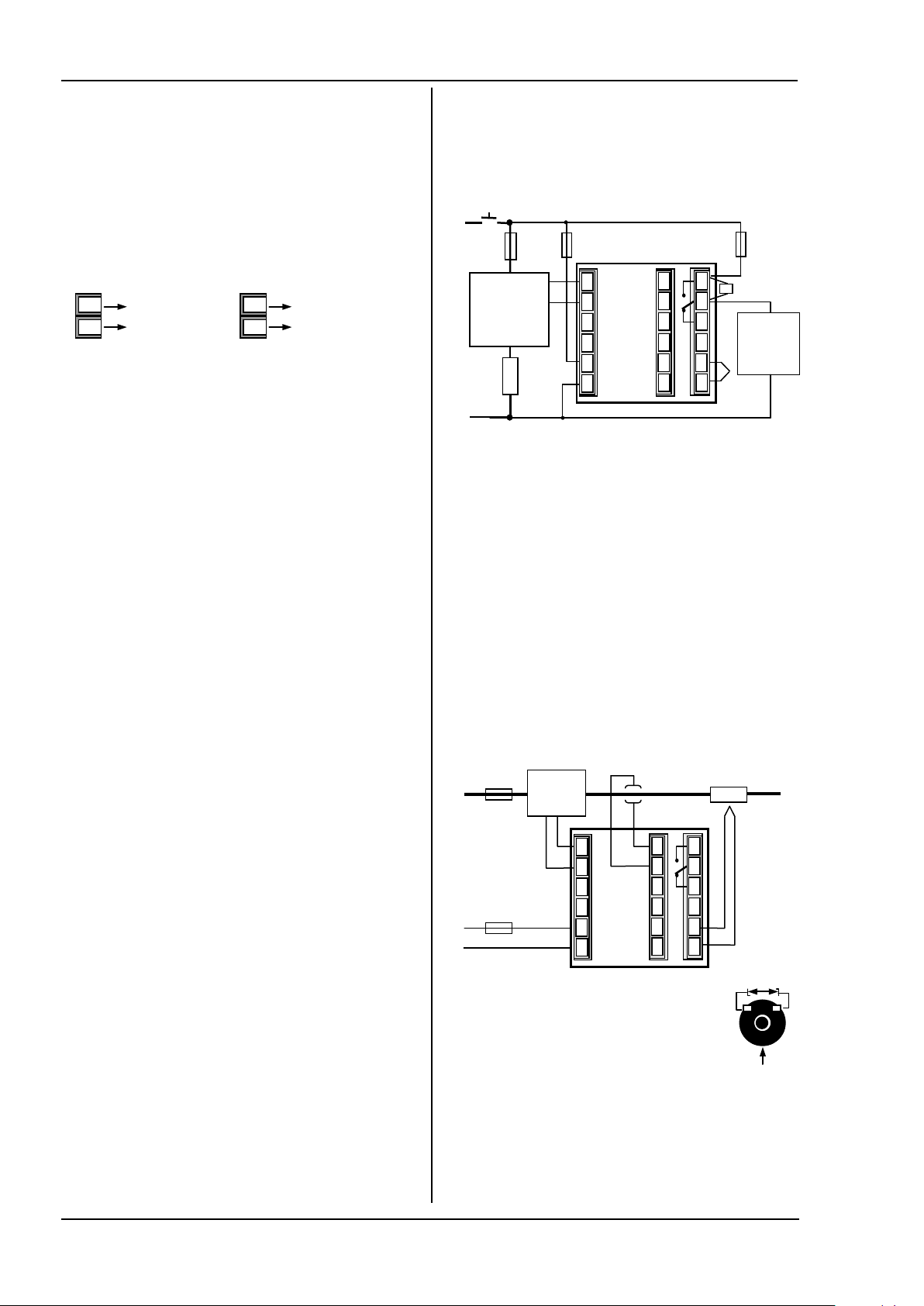
2.18 Example Heat/Cool Wiring
Diagram
This example shows a heat/cool temperature controller
where the heater control uses a SSR and the cooling
control uses a relay.
fuse
Solid State
Relay
(e.g. TE10)
AB
HD
HE
HF
C
AC
LA
VI
V+
V-
1B
2A
2B
L
N
Safety requirements for permanently connected
equipment state:
• A switch or circuit breaker shall be included in the
building installation
• It shall be in close proximity to the equipment and
within easy reach of the operator
• It shall be marked as the disconnecting device for
the equipment
A single switch or circuit breaker can drive more
than one instrument
2.18.1 Example CT Wiring Diagram
This diagram shows an example of wiring for a CT input.
Relay
(e.g. TE10)
C
LA
HD
HE
HF
AB
AC
VI
V+
V-
1B
2A
2B
L
N
Note: the burden resistor value 10Ω is
mounted inside the controller. It is
is fitted with a voltage limiting device such
as two back to back zener diodes between
3 and 10V and rated for 50mA.
output
fuse
alarm relay

3200 Series User Manual
Part No HA028651 Issue 15.0 Dec-15 17
3. Safety and EMC Information
This controller is intended for industrial temperature and
process control applications when it will meet the
requirements of the European Directives on Safety and
EMC. Use in other applications, or failure to observe the
installation instructions of this handbook may impair
safety or EMC. The installer must ensure the safety and
EMC of any particular installation.
Safety
This controller complies with the European Low Voltage
Directive 2006/95/EC by the application of the safety
standard EN 61010.
Electromagnetic compatibility
This controller conforms with the essential protection
requirements of the EMC Directive 2004/108/EC, by the
application of a Technical Construction File. This
instrument satisfies the general requirements of the
industrial environment defined in EN 61326. For more
information on product compliance refer to the
Technical Construction File.
GENERAL
The information contained in this manual is subject to
change without notice. While every effort has been
made to ensure the accuracy of the information, your
supplier shall not be held liable for errors contained
herein.
Unpacking and storage
The packaging should contain an instrument mounted in
its sleeve, two mounting brackets for panel installation
and an Installation & Operating guide. Certain ranges are
supplied with an input adapter.
If on receipt, the packaging or the instrument are
damaged, do not install the product but contact your
supplier. If the instrument is to be stored before use,
protect from humidity and dust in an ambient
temperature range of -30
SERVICE AND REPAIR
This controller has no user serviceable parts. Contact
your supplier for repair.
Caution: Charged capacitors
Before removing an instrument from its sleeve,
disconnect the supply and wait at least two minutes to
allow capacitors to discharge. It may be convenient to
partially withdraw the instrument from the sleeve, then
pause before completing the removal. In any case, avoid
touching the exposed electronics of an instrument when
withdrawing it from the sleeve.
Failure to observe these precautions may cause damage
to components of the instrument or some discomfort to
the user.
o
C to +75oC.
Electrostatic discharge precautions
When the controller is removed from its sleeve, some of
the exposed electronic components are vulnerable to
damage by electrostatic discharge from someone
handling the controller. To avoid this, before handling
the unplugged controller discharge yourself to ground.
Cleaning
Do not use water or water based products to clean labels
or they will become illegible. Isopropyl alcohol may be
used to clean labels. A mild soap solution may be used
to clean other exterior surfaces of the product.
3.1 Installation Safety Requirements
Symbols. If any of the symbols shown below are used
on the instrument they have the following meaning:
C CE Mark. W Refer to manual.
D Risk of electric shock.
O Take precautions against static ESD symbol.
4 5 Earth symbols.
P TCA-tick Australia (ACA) and New Zealand (RSM).
J Dispose of properly
* China RoSH (Wheel) Logo.
s Complies with the RoHS2 (2011/65/EU) directive.
r Earlier RoHS symbol (RoSH1).
— Protected by DOUBLE INSULATION.
(LX cUL Mark.
Helpful hints in this manual
Personnel
Installation must only be carried out by suitably qualified
personnel in accordance with the instructions in this
handbook.
Enclosure of Live Parts
To prevent hands or metal tools touching parts that may
be electrically live, the controller must be enclosed in an
enclosure.
Caution: Live sensors
The controller is designed to operate if the temperature
sensor is connected directly to an electrical heating
element. However you must ensure that service
personnel do not touch connections to these inputs
while they are live. With a live sensor, all cables,
connectors and switches for connecting the sensor must
be mains rated.
Wiring
It is important to connect the controller in accordance
with the wiring data given in this guide. Take particular
care not to connect AC supplies to the low voltage
sensor input or other low level inputs and outputs. Only
use copper conductors for connections (except
thermocouple inputs) and ensure that the wiring of
installations comply with all local wiring regulations. For
example in the UK use the latest version of the IEE wiring
regulations, (BS7671). In the USA use NEC Class 1 wiring
methods.

User Manual 3200 Series
18 Part No HA028651 Issue 15.0 Dec-15
Power Isolation
The installation must include a power isolating switch or
circuit breaker. This device should be in close proximity to
the controller, within easy reach of the operator and marked
as the disconnecting device for the instrument.
Overcurrent protection
The power supply to the system should be fused
appropriately to protect the cabling to the units.
Voltage rating
The maximum continuous voltage applied between any
of the following terminals must not exceed 240Vac:
• relay output to logic, dc or sensor connections;
• any connection to ground.
The controller must not be wired to a three phase supply
with an unearthed star connection. Under fault
conditions such a supply could rise above 240Vac with
respect to ground and the product would not be safe.
Conductive pollution
Electrically conductive pollution must be excluded from
the cabinet in which the controller is mounted. For
example, carbon dust is a form of electrically conductive
pollution. To secure a suitable atmosphere in conditions
of conductive pollution, fit an air filter to the air intake
of the cabinet. Where condensation is likely, for
example at low temperatures, include a thermostatically
controlled heater in the cabinet.
This product has been designed to conform to BSEN61010
installation category II, pollution degree 2. These are
defined as follows:-
Installation Category II (CAT II)
The rated impulse voltage for equipment on nominal 230V
supply is 2500V.
Pollution Degree 2
Normally only non conductive pollution occurs.
Occasionally, however, a temporary conductivity caused by
condensation shall be expected.
Grounding of the temperature sensor shield
In some installations it is common practice to replace the
temperature sensor while the controller is still powered
up. Under these conditions, as additional protection
against electric shock, we recommend that the shield of
the temperature sensor is grounded. Do not rely on
grounding through the framework of the machine.
Over-temperature protection
When designing any control system it is essential to
consider what will happen if any part of the system
should fail. In temperature control applications the
primary danger is that the heating will remain constantly
on. Apart from spoiling the product, this could damage
any process machinery being controlled, or even cause a
fire.
Reasons why the heating might remain constantly on
include:
• the temperature sensor becoming detached from the
process
• thermocouple wiring becoming short circuit;
• the controller failing with its heating output
constantly on
• an external valve or contactor sticking in the heating
condition
• the controller setpoint set too high.
Where damage or injury is possible, we recommend
fitting a separate over-temperature protection unit, with
an independent temperature sensor, which will isolate
the heating circuit.
Please note that the alarm relays within the controller
will not give protection under all failure conditions.
Installation requirements for EMC
To ensure compliance with the European EMC directive
certain installation precautions are necessary as follows:
• For general guidance refer to Eurotherm Controls
EMC Installation Guide, HA025464.
• When using relay outputs it may be necessary to fit a
filter suitable for suppressing the emissions. The
filter requirements will depend on the type of load.
• If the unit is used in table top equipment which is
plugged into a standard power socket, then it is likely
that compliance to the commercial and light
industrial emissions standard is required. In this case
to meet the conducted emissions requirement, a
suitable mains filter should be installed.
Routing of wires
To minimise the pick-up of electrical noise, the low
voltage DC connections and the sensor input wiring
should be routed away from high-current power cables.
Where it is impractical to do this, use shielded cables
with the shield grounded at both ends. In general keep
cable lengths to a minimum.

3200 Series User Manual
Part No HA028651 Issue 15.0 Dec-15 19
4. Switch On
The way in which the controller starts up depends on
factors described below in sections 4.1, 4.2 and 4.3.
4.1 New Controller
If the controller is new AND has not previously been
configured it will start up showing the ‘Quick
Configuration’ codes. This is a built in tool which
enables you to configure the input type and range, the
output functions and the display format.
Incorrect configuration can result in damage to
the process and/or personal injury and must be carried
out by a competent person authorised to do so. It is the
responsibility of the person commissioning the controller
Adjust these as follows:-.
1. Press any button
. The characters will change to ‘-‘,
the first one flashing.
2. Press
or
to change the flashing character to
the required code shown in the quick code tables –
see below. Note: An
x indicates that the option is
not fitted.
3. Press
to scroll to the next character.
You cannot scroll to the next character until the
current character is configured.
To return to the first character press
4. When all five characters have been configured the
display will go to Set 2.
5. When the last digit has been entered press
to ensure the configuration is correct
again, the display will show
4.1.1 Quick Start Code
The quick start code consists of two ‘SETS’
of five characters. The upper section of the
display shows the set selected, the lower
Press
The controller will then automatically go to the operator
level, section 4.3.
section shows the five digits which make up the set.
SET 1
Input type Range Input/Output 1 Output 2 Output 4
Thermocouple Full range X Unconfigured
B Type B C oC H PID Heating [logic, relay (1) or 4-20mA] or motor valve open [VC and VP only] Note (1) O/P4 is
J Type J F oF C PID Cooling [logic, relay (1) or 4-20mA] or motor valve close [VC and VP only]
K Type K Centigrade J ON/OFF Heating [logic or relay (1)], or PID 0-20mA heating
L Type L 0 0-100 K ON/OFF Cooling [logic or relay (1)], or PID 0-20mA cooling
N Type N 1 0-200 Alarm (2): energised in alarm Alarm (2): de-energised in alarm
R Type R 2 0-400 0 High alarm 5 High alarm Note (2)
S Type S 3 0-600 1 Low alarm 6 Low alarm
T Type T 4 0-800 2 Deviation high 7 Deviation high
C Custom 5 0-1000 3 Deviation low 8 Deviation low
RTD 6 0-1200 4 Deviation band 9 Deviation band
P Pt100 7 0-1400
Linear 8 0-1600 D 4-20mA Setpoint N 0-20mA Setpoint
M 0-80mV 9 0-1800 E 4-20mA Temperature Y 0-20mA Temperature
2 0-20mA Fahrenheit F 4-20mA output Z 0-20mA output
4 4-20mA G 32-212 Logic input functions (Input/Output 1 only)
H 32-392 W Alarm acknowledge V Recipe 2/1 select
J 32-752 M Manual select A Remote UP button
K 32-1112 R Timer/program run B Remote DOWN button
L 32-1472 L Keylock G Timer/Prog Run/Reset
M 32-1832 P Setpoint 2 select I Timer/Program Hold
N 32-2192 T Timer/program Reset Q Standby select
P 32-2552 U Remote SP enable
R 32-2912
T 32-3272
DC Retransmission (not O/P4)
or
to .
relay only.
OP1 = alarm 1
OP2 = alarm 2
OP3 = alarm 3
OP4 = alarm 4

User Manual 3200 Series
20 Part No HA028651 Issue 15.0 Dec-15
SET 2
Measured Temperature
Target Temperature
Input CT Scaling Digital Input A Digital Input B (2) Output 3 (2) Lower Display
X
1
2
5
6
Note (1)
OP1 = alarm 1 (I/O1)
OP2 = alarm 2
OP3 = alarm 3
OP4 = alarm 4 (AA)
3208 & 3204 only
VP, VC only
4.2 To Re-Enter Quick Code mode
If you need to re-enter the ‘Quick Configuration’ mode
this can always be done as follows:-
1. Power down the controller
2. Hold down the
controller again.
3. Keep the button pressed until code is displayed.
4. Enter the configuration code (this is defaulted to 4
in a new controller)
5. The quick start codes may then be set as described
previously
Parameters may also be configured using a deeper
level of access. This is described in later chapters of this
handbook.
If the controller is started with the
down, as described above, and the quick start codes are
shown with dots (e.g. J.C.X.X.X), this indicates that the
controller has been re-configured in a deeper level of
access and, therefore, the quick start codes may not be
valid. If the quick start codes are accepted by scrolling
to
X
W Alarm acknowledge H PID heating or motor valve open (3) P Output
M Manual select C PID cooling or motor valve close (3) R Time remaining
R Timer/Program Run J ON/OFF heating (not shown if VC or VP) E Elapsed time
L Keylock K ON/OFF cooling (not shown if VC or VP) 1 Alarm setpoint
P Setpoint 2 select Alarm Outputs (1) A Load Amps
T Timer/Program reset Energised in alarm De-energised in alarm D Dwell/Ramp
U Remote SP enable 0 High alarm 5 High alarm Time/Target
V Recipe 2/1 select 1 Low alarm 6 Low alarm N None
A Remote UP button 2 Dev High 7 Dev High C Setpoint with
B Remote DOWN button 3 Dev Low 8 Dev Low Output meter (2)
G Timer/Prog Run/Reset 4 Dev Band 9 Dev Band M Setpoint with
I Timer/Program Hold DC outputs Ammeter (2)
Q Standby select H 4-20mA heating
C 4-20mA cooling
K 0-20mA cooling
Retransmission output
D 4-20 Setpoint
E 4-20 Measured Temperature
F 4-20mA output
N 0-20 Setpoint
Y 0-20 Measured Temperature
Z 0-20mA output
button, and power up the
button held
then the quick start codes are reinstated.
X Unconfigured T Setpoint (std)
J 0-20mA heating
4.3 Pre-Configured Controller or
Subsequent Starts
A brief start up sequence consists of a self test during
which the software version number is shown followed
briefly by the quick start codes.
It will then proceed to Operator Level 1..
You will see the display shown below. It is called the
HOME display.
will show red if an
alarm is present.
The OP4 beacon
will be on if output
4 is active
(or Process Value ‘PV’)
(Setpoint ‘SP’)
If the quick start codes do not appear during this
start up, it means that the controller has been configured
in a deeper level of access, see the note in section 4.2.
The quick start codes may then not be valid and are
therefore not shown.

3200 Series User Manual
Part No HA028651 Issue 15.0 Dec-15 21
4.4 Front Panel Layout
Measured Temperature
Target Temperature
Meter (3208 and 3204 only) –configurable as:
ALM Alarm active (Red)
OP1 lit when output 1 is ON (normally heating)
OP2 lit when output 2 is ON (normally cooling )
OP3 lit when output 3 is ON
OP4 lit when output 4 relay is ON (normally alarm)
SPX Alternative setpoint in use (e.g. setpoint 2)
REM Remote digital setpoint. Also flashes when digital
communications active
RUN Timer/programmer running
RUN (flashing) Timer/programmer in hold
MAN Manual mode selected
Operator Buttons:-
From any view — press to return to the HOME
display
Press to select a new parameter. If held down it
will continuously scroll through parameters.
Press to decrease a value
Press to increase a value
4.4.2 Alarms
Process alarms may be configured using the Quick Start
Codes section 4.1.1. Each alarm can be configured for:-
Full Scale Low The alarm is shown if the process value falls
Full Scale High The alarm is shown if the process value rises
Deviation Low The alarm is shown if the process value deviates
Deviation High The alarm is shown if the process value deviates
Deviation Band The alarm is shown if the process value deviates
If an alarm is not configured it is not shown in the list of
level 2 parameters, section 5.3.
Additional alarm messages may be shown such as
CONTROL LOOP BROKEN. This occurs if the controller
does not detect a change in process value following a
change in output demand after a suitable delay time.
Another alarm message may be INPUT SENSOR BROKEN
(SBr). This occurs if the sensor becomes open circuit;
the output level will adopt a ‘SAFE’ value which can be
set up in Operator Level 3, see section 11.2.
below a set threshold
above a set threshold
below the setpoint by a set threshold
above the setpoint by a set threshold
above or below the setpoint by a set threshold
From firmware version 2.11 two further alarm types
have been made available. These are:-
Rising rate
of change
Falling rate
of change
These alarms cannot be configured by the Quick Start
Code – they can only be configured in Configuration
Mode, see section 12.3.
An alarm will be detected if the rate of change
(units/minute) in a positive direction exceeds the
alarm threshold
An alarm will be detected if the rate of change
(units/minute) in a negative direction exceeds the
alarm threshold
(or Process Value ‘PV’)
(Setpoint ‘SP’)
— Off
— Heat or cool output
— Output (Centre zero)
— Load Amps from CT
— Error signal
4.4.1 To Set The Target Temperature.
From the HOME display:-
Press
Press
to raise the setpoint
to lower the setpoint
The new setpoint is entered when the button is
released and is indicated by a brief flash of the
display.
4.4.3 Alarm Indication
If an alarm occurs, the red ALM beacon will flash. A
scrolling text message will describe the source of the
alarm. Any output (usually a relay) attached to the alarm
will operate. An alarm relay can be configured using the
Quick Start Codes to be energised or de-energised in the
alarm condition. It is normal to configure the relay to be
de-energised in alarm so that an alarm is indicated if
power to the controller fails.
Press
If the alarm is still present the ALM beacon will light
continuously otherwise it will go off.
The action which takes place depends on the type of
alarm configured:-
Non
latching
Auto
Latching
Manual
Latching
By default alarms are configured as non-latching, deenergised in alarm. To configure latched alarms, refer to
section 12.3.1.
Note: If remote setpoint is configured ensure that the
remote input is connected or the relevant rear terminals
are linked. If the remote setpoint input is left open
circuit the alarm beacon will light.
and
(ACK) together to acknowledge
A non latching alarm will reset itself when the
alarm condition is removed. By default alarms
are configured as non-latching, de-energised in
alarm.
An auto latching alarm requires
acknowledgement before it is reset. The
acknowledgement can occur BEFORE the
condition causing the alarm is removed.
The alarm continues to be active until both the
alarm condition is removed AND the alarm is
acknowledged. The acknowledgement can only
occur AFTER the condition causing the alarm is
removed.

User Manual 3200 Series
22 Part No HA028651 Issue 15.0 Dec-15
4.4.4 Auto, Manual and Off Mode
The controller can be put into Auto, Manual or Off
mode – see next section.
Auto mode is the normal operation where the output is
adjusted automatically by the controller in response to
changes in the measured temperature.
In Auto mode all the alarms and the special functions
(auto tuning, soft start, timer and programmer) are
operative
Manual mode means that the controller output power
is manually set by the operator. The input sensor is still
connected and reading the temperature but the control
loop is ‘open’.
In manual mode the MAN beacon will be lit, Band and
deviation alarm are masked, the auto-tuning timer and
programmer functions are disabled.
The power output can be continuously increased or
decreased using the
or
buttons.
4.4.5 To Select Auto, Manual or Off Mode
Press and hold
more than 1 second.
This can only be accessed from the HOME display.
1. Auto’ is shown in the upper display.
After 5 seconds the lower display will
scroll the longer description of this
parameter. ie ’ lo o p m o d e – a u to
m anua l o ff’
2. Press
to select ‘OFF’. This is shown in the
upper display.
3. When the desired Mode is selected,
do not push any other button. After
2 seconds the controller will return to
the HOME display.
4. If OFF has been selected, OFF will be shown in the
lower display and the heating and cooling outputs
will be off
and
(Mode) together for
to select ‘mAn’. Press again
Manual mode must be used with care. The
power level must not be set and left at a value that
can damage the process or cause over-heating. The
use of a separate ‘over-temperature’ controller is
recommended.
Off mode means that the heating and cooling outputs
are turned off. The process alarm and analogue
retransmission outputs will, however, still be active
while Band and deviation alarm will be OFF.
5. If manual mode has been selected, the MAN beacon
will light. The upper display shows the measured
temperature and the lower display the demanded
output power.
The transfer from Auto to manual mode is ‘bumpless’.
This means the output will remain at the current
value at the point of transfer. Similarly when
transferring from Manual to Auto mode, the current
value will be used. This will then slowly change to
the value demanded automatically by the controller.
6. To manually change the power output, press
to lower or raise the output. The output power
is continuously updated when these buttons are
pressed
7. To return to Auto mode, press
together. Then press
to select ‘Auto’.
and
or

3200 Series User Manual
Part No HA028651 Issue 15.0 Dec-15 23
4.4.6 Level 1 Operator Parameters
A minimal list of parameters are available in operator
Level 1 which is designed for day to day operation.
Access to these parameters is not protected by a pass
code.
Press
mnemonic of the parameter is shown in the lower
display. After five seconds a scrolling text description of
the parameter appears.
The value of the parameter is shown in the upper
display. Press
is pressed for 30 seconds the controller returns to the
HOME display
The parameters that appear depend upon the functions
configured. They are:-
Mnemonic
WRK.OP
WKG.SP WORKING
SP1 SETPOINT 1 Alterable
SP2 SETPOINT 2 Alterable
T.REMN TIME REMAINING
DWELL SET TIME
A1.xxx
A2.xxx ALARM 2 SETPOINT
A3.xxx ALARM 3 SETPOINT
A4.xxx ALARM 3 SETPOINT
LD.AMP LOAD CURRENT Read only. Only shown if
to step through the list of parameters. The
Parameter
or
to adjust this value. If no key
Scrolling Display
and Description
The active output
value
SETPOINT
The active setpoint
value.
Time to end of set
period
DURATION Timer
set time
Alterability
Read only.
Appears when the
controller is in AUTO or
OFF mode.
In a motorised valve
controller (option VC or
VP) this is the ‘inferred’
position of the valve
Read only.
Only shown when the
controller is in MAN or
OFF mode.
Read only
0:00 to 99.59 hh:mm or
mm:ss
Alterable. Only shown if
timer (not programmer)
configured.
Read only.
Only shown if the alarm is
configured.
xxx = alarm type as
follows:-
HI = High alarm
LO = Low alarm
d.HI = Deviation high
d.LO = Deviation low
d.HI = Deviation high
rrc = Rising rate of change
(units/minute)
Frc = Falling rate of
change
(units/minute)
CT is configured
5. Operator Level 2
Level 2 provides access to additional parameters. Access
to these is protected by a security code.
5.1 To Enter Level 2
1. From any display press and hold
2. After a few seconds the display will
show:-
3. Release
.
(If no button is pressed for about 45 seconds the display
returns to the HOME display)
4. Press
or
to
choose Lev 2 (Level 2)
5. After 2 seconds the
display will show:-
or
6. Press
to enter the
pass code. Default = ‘2’
• If an incorrect code is entered the controller reverts
to Level 1.
5.2 To Return to Level 1
1. Press and hold
2. Press
to select LEv 1
The controller will return to the level 1 HOME display.
Note: A security code is not required when going from a
higher level to a lower level.
5.3 Level 2 Parameters
Press
mnemonic of the parameter is shown in the lower display.
After five seconds a scrolling text description of the
parameter appears.
The value of the parameter is shown in the upper display.
Press
for 30 seconds the controller returns to the HOME display
Backscroll is achieved when you are in this list by pressing
The following table shows a list of parameters available in
Level 2.
to step through the list of parameters. The
or
to adjust this value. If no key is pressed
while holding down
.
.

User Manual 3200 Series
24 Part No HA028651 Issue 15.0 Dec-15
Mnemonic Scrolling Display and description Range
WKG.SP
WORKING SETPOINT is the active setpoint value and appears when the
SP.HI to SP.LO
controller is in Manual mode. It may be derived from SP1 or SP2, or, if the
controller is ramping (see SP.RAT), it is the current ramp value.
WRK.OP WORKING OUTPUT is the output from the controller expressed as a percentage
of full output. It appears when the controller is in Auto mode.
In a motorised valve controller (option VC or VP) this is the ‘inferred’ position of
the valve
For a time proportioning output, 50% = relay or logic output on or off for equal
lengths of time.
Read only value
0 to 100% for heating
0 to –100% for cooling
-100 (max cooling) to 100%
(max heating
For On/Off control: OFF = <1%. ON = >1%
T.STAT TIMER STATUS is the current state of the timer: Run, Hold, Reset or End
It is only appears when a timer is configured.
UNITS DISPLAY UNITS Temperature display units. ‘Percentage’ is provided for
linear inputs
rES
run
hoLd
End
O
C
O
F
O
k
nonE
PErc
Reset
Running
Hold
Timed out
Degrees C
Degrees F
Degrees K
None
Percentage
SP.HI SETPOINT HIGH High setpoint limit applied to SP1 and SP2. Alterable between range limits
SP.LO SETPOINT LOW Low setpoint limit applied to SP1 and SP2
By default the remote setpoint is scaled between SP.HI and SP.LO. Two further parameters (REM.HI and REM.LO) are
available in access level 3 to limit the Remote SP range if required. See section 10.1.
SP1 SETPOINT 1 allows control setpoint 1 value to be adjusted Alterable: SP.HI to SP.LO
SP2 SETPOINT 2 allows control setpoint 2 value to be adjusted Alterable: SP.HI to SP.LO
SP.RAT SETPOINT RATE LIMIT Rate of change of setpoint value. OFF to 3000 display units per
minute
The next section applies to the Timer only – see also section 5.4.
TM.CFG TIMER CONFIGURATION Configures the timer type:- Dwell, Delay, Soft Start or
none. The timer type can only be changed when the timer is reset.
The Programmer option only appears if the programmer has been ordered.
TM.RES TIMER RESOLUTION Selects the resolution of the timer. This can only be
changed when the timer is reset.
THRES TIMER START THRESHOLD The timer starts timing when the temperature is
none
Dwel
DeLy
sfst
Prog
Hour
min
None
Dwell
Delayed switch on
Soft start
Programmer
Hours
Minutes
OFF or 1 to 3000
within this threshold of the setpoint. This provides a guaranteed soak
temperature. The threshold can be set to OFF in which case it is ignored and
the timing starts immediately.
If a setpoint ramping is set, then the ramp completes before the timer starts.
END.T TIMER END TYPE This determines the behaviour of the timer when it has timed
out. This value can be changed while the timer is running.
OFF
Dwel
Control OP goes to
zero
Control continues at
SP1
SS.PWR SOFT START POWER LIMIT This parameter only appears if the timer
SP2
res
-100 to 100%
Go to SP2
Reset programmer
configuration is set to sfst (Softstart). It sets a power limit which is applied
until the measured temperature reaches a threshold value (SS.SP) or the set
time (DWELL) has elapsed. The timer starts automatically on power up.

3200 Series User Manual
Part No HA028651 Issue 15.0 Dec-15 25
Mnemonic Scrolling Display and description Range
SS.SP SOFT START SETPOINT This parameter only appears if the timer configuration
Between SP.HI and SP.LO
is set to sfst (Softstart). It sets the threshold value below which the power is
limited
DWELL SET TIME DURATION — Sets the dwell timing period. It can be adjusted while
0:00 to 99.59 hh:mm: or mm:ss
the timer is running.
T.REMN TIME REMAINING Timer time remaining. This value can be increased or
0:00 to 99.59 hh:mm: or mm:ss
decreased while the timer is running
The following parameters are available when the timer is configured as a programmer – see also section 13.2
SERVO SERVO MODE. Sets the starting point for the ramp/dwell programmer and the
action on recovery from power failure.
SP
PV
SP.rb
PV.rb
Setpoint
Process variable
Ramp back to SP
Ramp back to PV
TSP.1 TARGET SETPOINT 1. To set the target value for the first setpoint
RMP.1 RAMP RATE 1. To set the first ramp rate OFF, 0:01 to 3000 units per min
or hour as set by TM.RES
DWEL.1 DWELL 1. To set the period of the first dwell OFF, 0:01 to 99:59 hh:mm or
mm:ss as set by TM.RES
The above three parameters are repeated for the next three program segments, i.e. TSP.2 (3 & 4), RMP.2 (3 & 4), DWEL.2 (3 & 4)
This section applies to Alarms only If an alarm is not configured the parameters do not appear
A1.— — to
A4.—
ALARM 1 (2, 3 or 4) SETPOINT sets the threshold value at which an alarm
occurs. Up to four alarms are available and are only shown if configured.
SP.HI to SP.LO
The last three characters in the mnemonic specify the alarm type:-
Lo
dH i
rr
c
Full Scale Low
Deviation High
Rising rate of
change
Hi
dLo
F rc
Full Scale High
Deviation Low
Falling rate of
change
Bnd
Deviation Band
1 to 9999 units/minute
The following parameter is present if a motorised valve controller has been ordered
MTR.T MOTOR TRAVEL TIME. Set this value to the time that it takes for the motor to
0.0 to 999.9 seconds
travel from its fully closed to its fully open position.
Note: In motorised valve control only the PB and TI parameters are active – see
below. The TD parameter has no effect on the control.
This section applies to control the parameters. A further description of theses parameters is given in section 11
A.TUNE AUTOTUNE automatically sets the control parameters to match the process
characteristics.
PB PROPORTIONAL BAND sets an output which is proportional to the size of the
error signal. Units may be % or display units.
TI INTEGRAL TIME removes steady state control offsets by ramping the output up
or down in proportion to the amplitude and duration of the error signal.
TD DERIVATIVE TIME determines how strongly the controller will react to the rate
of change in the process value. It is used to prevent overshoot and undershoot
and to restore the PV rapidly if there is a sudden change in demand.
MR MANUAL RESET applies to a PD only controller i.e. the integral term is turned
off. Set this to a value of power output (from +100% heat, to -100% cool which
Off
On
Disable
Enable
1 to 9999 display units
Default 20
Off to 9999 seconds
Default 360
Off to 9999 seconds
Default 60 for PID control
Default 0 for VP control
-100 to 100%
Default 0
removes any steady state error between SP and PV.
R2G RELATIVE COOL GAIN adjusts the cooling proportional band relative to the
heating proportional band. Particularly necessary if the rate of heating and rate
0.1 to 10.0
Default 1.0
of cooling are very different. (Heat/Cool only)
HYST.H HEATING HYSTERESIS Sets the difference in temperature units between heating
turning off and turning on when ON’OFF control is used. Only appears if
0.1 to 200.0 display units
0.2 Default 1.0
channel 1(heating) control action is On/Off
HYST.C COOLING HYSTERESIS Sets the difference in temperature units between
cooling turning off and turning on when ON/OFF control is used. Only appears
0.1 to 200.0 display units
Default 1.0

User Manual 3200 Series
26 Part No HA028651 Issue 15.0 Dec-15
Mnemonic Scrolling Display and description Range
if channel 2 (cooling) control action is On/Off
D.BAND CHANNEL 2 DEADBAND adjusts a zone between heating and cooling outputs
when neither output is on. Off = no deadband. 100 = heating and cooling off.
Only appears if On/Off control configured.
OP.HI OUTPUT HIGH limits the maximum heating power applied to the process or a
minimum cooling output.
1. (2, 3 or 4)
PLS.
This section applies to current transformer input only. If the CT option is not configured the parameters do not appear.
LD.AMP LOAD CURRENT is the measured load current when the power demand is on CT Range
LK.AMP LEAK CURRENT is the measured leakage current when the power demand is off. CT Range
LD.ALM LOAD CURRENT THRESHOLD Sets a low alarm on the load current measured
LK.ALM LEAK CURRENT THRESHOLD sets a high alarm on the leakage current
HC.ALM OVERCURRENT THRESHOLD Sets a high alarm on the load current measured
ADDR ADDRESS — communications address of the controller. 1 to 254 1 to 254
HOME HOME DISPLAY Defines the parameter which appears in the lower section of
ID CUSTOMER ID Sets a number from 0 to 9999 used as a custom defined
REC.NO CURRENT RECIPE NUMBER Displays the current recipe number. If this
STORE RECIPE TO SAVE Saves the current parameter values into a selected recipe
OUTPUT 1 (2, 3 or 4) MINIMUM PULSE TIME Sets the minimum on and off
time for the control output.
Ensure this parameter is set to a value that is suitable for the
output switching device in use. For example, if a logic output is used to
switch a small relay, set the value to 5.0 seconds or greater to prevent
damage to the device due to rapid switching.
by the CT. Used to detect partial load failure.
measured by the CT.
by the CT
the HOME display.
identification number for the controller.
number is changed, the parameter values stored under the selected recipe
number will be loaded. See the engineering manual for more information about
recipes.
number. Up to 5 recipes can be saved.
OFF or 0.1 to 100.0% of the
cooling proportional band
+100% to OP.LO
Relay outputs 0.1 to 150.0
seconds – default 5.0.
Logic outputs Auto to 150.0 —
Default Auto = 55ms
CT Range
CT Range
CT Range
STD
OP
Tr
ELAP
AL
CT
CLr
TMr
0 to 9999
none or 1 to 5 or
FaiL if no recipe set stored
none or 1 to 5
done when stored
Standard
Output power
Time remaining
Time elapsed
First alarm setpoint
Load current
Clear (blank)
Combined setpoint
and time display
Press
Hold
at any time to return immediately to the HOME screen at the top of the list.
down to continuously scroll through the above list

3200 Series User Manual
Part No HA028651 Issue 15.0 Dec-15 27
5.4 Timer Operation
An internal timer can be set to operate in one of four different modes. The mode is set in Level 2 by the ‘TM.CFG’
(timer configuration) parameter. Each Timing Mode is described in the pages that follow.
5.5 Dwell Timer
A dwell timer (‘TM.CFG’ = ‘DwEl’) is used to control a process at a fixed temperature for a defined period.
In reset the controller behaviour depends on the configuration of the END state parameter. See opposite.
In run the heating or cooling will come on. Timing starts when the temperature is within the threshold ‘THRES’ of the
setpoint. If the threshold is set to OFF the timing starts immediately.
If setpoint ramping is enabled, then the ramp completes before the timer starts.
In the END state the behaviour is determined by the parameter ‘END.T’ (End type):
OFF The heating and cooling is turned OFF (resets to Off)
Dwel Controls at setpoint1 (resets to Setpoint 1)
SP2 Controls at setpoint 2 (resets to Setpoint 1)
rES Reset reverts to SP1.– (added from version V2.13)
Note: The dwell period can be reduced or increased while the timer is running.
Flashing display message
RUN Digital Output = t.run
END Digital Output = t.End
Temperature
SP1
Run
Timer Duration
t.dUr
rUn
OFF SP2 DLL res
PV
End
rUn
End/OFF
Ramping
Setpoint
SP2
rUn End
rUn
Time

User Manual 3200 Series
28 Part No HA028651 Issue 15.0 Dec-15
5.6 Delayed Timer
‘TM.CFG’ = ‘DELY’. The timer is used to switch on the output power after a set time. The timer starts immediately on
power-up, or when run.
The controller remains in standby with heating and cooling off until the time has elapsed. After the time has elapsed, the
instrument controls at the target setpoint.
Temperature
SP1 (70)
Scrolling Message
TIMER RUNNING
TIMER END
Time
Run
Reset
RESET Digital input
RUN Digital O/P = t.run
END Digital O/P = t.End
Loading…
- About
- Blog
- Projects
- Help
-
Donate
Donate icon
An illustration of a heart shape - Contact
- Jobs
- Volunteer
- People
Bookreader Item Preview
texts
Eurotherm 3216i User guide
- Addeddate
- 2021-02-25 12:40:33
- Identifier
- manualzz-id-1328423
- Identifier-ark
- ark:/13960/t6rz9hg19
- Ocr
- tesseract 5.0.0-alpha-20201231-7-gc75f
- Ocr_autonomous
- true
- Ocr_detected_lang
- en
- Ocr_detected_lang_conf
- 1.0000
- Ocr_detected_script
-
Latin
Cyrillic
- Ocr_detected_script_conf
-
0.9958
0.0042
- Ocr_module_version
- 0.0.11
- Ocr_parameters
- -l lat+kir+eng+kaz+Cyrillic+Latin
- Page_number_confidence
- 97.78
comment
Reviews
There are no reviews yet. Be the first one to
write a review.
51
Views
DOWNLOAD OPTIONS
Temporarily Unavailable
DAISY
For users with print-disabilities
Temporarily Unavailable
EPUB
Uploaded by
chris85
on
SIMILAR ITEMS (based on metadata)
3204, 3216, 3208, 32h8 Temperature / Process Controllers
The innovative range of 3200 series controller offers precision control of temperature and other process variables together with a host of advanced features not normally found in this class of controller.
- Description
- Specification
- Downloads
Description
- QuickStart set-up enabling ‘out of the box’ operation
- Expert configuration via PC wizard with online help
- Quick and easy commissioning – no need for expert knowledge
- Clear information of process with scrolling, custom messages
- Custom alarm messages for easy understanding
- Recipe selection from operator interface
- Internal timer and setpoint programming
- Instant indication of heater faults with integral ammeter
- Remote setpoint – solution for multi-zone applications
The emphasis is on simplicity and ease of use. A simple ‘QuickStart’ code can be used to configure all the functions essential for controlling your process. This includes input sensor type, measurement range, control options and alarms – making ‘Out of the Box’ operation truly achievable. If you prefer, you can specify what you need at point of order and we will ship the unit preconfigured to your requirements.
In operator mode every parameter has a scrolling text message describing its function and is available in English, German, French, Spanish or Italian. More advanced features are configured using Eurotherm iTools, a PC based configuration wizard which is easy to use and an instructive guide to all the functions in the controller.
Ideal for:
- Plastics – extrusion
- Heat treatment
- Hot runner
- Thermal forming
- Ovens & chillers
- Stress relieving
Features:
- 8 Segment programmer
- Heater failure detection
- Current monitoring
- Internal timer
- Scrolling text messages
- Recipes
- Modbus comms
- Modbus SP retransmission
- Analog retransmission
- Remote setpoint
- Help text
Specification
| Input Type |
CT, mA, mV, RTD, TC |
|---|---|
| PV Accuracy |
<0.25% |
| IP Rating |
IP65, NEMA 12 / NEMA 4X (3216 Only) |
| Display Type |
Main: 4 digits Lower: 5 character starburst (3216/08/04) 9 character starburst (32h8) |
| Control Types |
On/Off, PID, VP |
| Alarm Types |
Dev, Event, Heater fail, Hi, Lo, Sensor Break |
| Supply Voltage |
24V dc/ac, 85-264V ac |
| SP Programmer |
4 Ramp + 4 Dwell |
| Real Time Clock |
– |
| Safety-approvals |
EN14597 TR |
| Special Features |
Recipes, Text Messaging |
| Analogue IP/OP In |
2 |
| Analogue IP/OP Out |
3 |
| Digital IP/OP In |
3 |
| Digital IP/OP Out |
4 |
| Digital Comms |
Modbus |
| Maths Equation |
None |
| Combinational Logic |
None |
| Timers/Counters/Totals |
None |
| PC Configuration |
Wizard |
Downloads
All
Brochure
CAD
Case Study
Certificate
Data Sheet
Essential
Note App
Software
Terms & Conditions
User Guide
Whitepaper