
* — Также подходит к моделям Talking Camera, Barbie, One Step и им подобным.

Устройство фотоаппарата
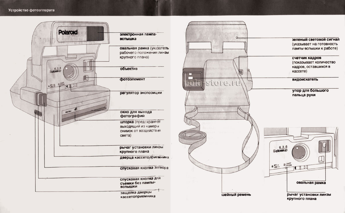
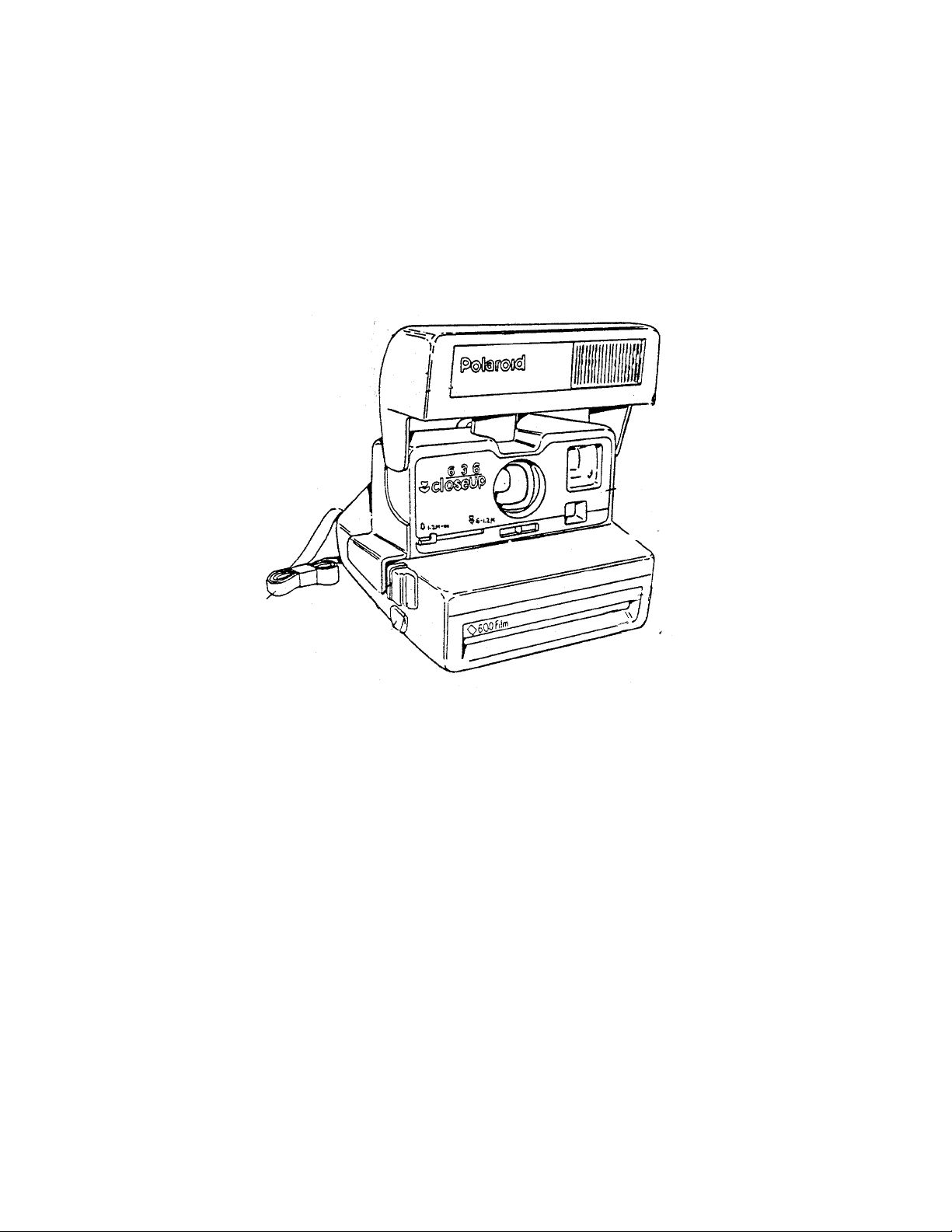
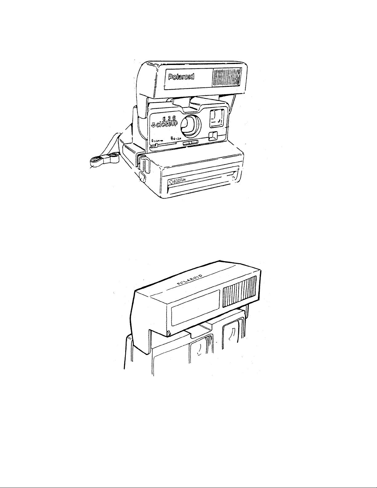
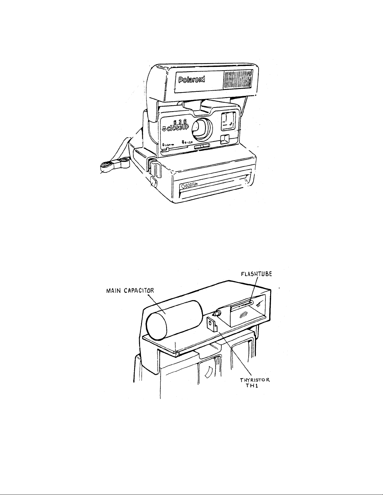
Электронная лампа-вспышка, овальная рамка (указатель рабочего положения линзы крупного плана), объектив, фотоэлемент, регулятор экспозиции, окно для выхода фотографий, шторка (предохраняет выходящий из камера снимок от воздействия света) , рычаг установки линзы, крупного плана, дверца кассетоприемника, спусковая кнопка загвора, спусковая кнопка для съемки без лампы-вспышки, защелка дверцы кассетоприемника, зеленый световой сигнал (указывает на готовность лампы-вспышки к работе), счетчик кадров (показывает количество кадров, оставшихся в кассете), видоискатель, упор для большого пальца руки, шейный ремешок, овальная рамка, рычаг установки линзы крупного плана
Подготовка лампы-вспышки к съемке
Возьмитесь за боковые поверхности лампы-вспышки и поворотом вверх зафиксируйте ее в рабочем положении. Вспышка автоматически перезаряжается в течение 3-х секунд после ее установки в рабочее положение при наличии пленки в фотоаппарате, а также после очередной съемки или при легком нажатии на спусковую кнопку затвора. Применение вспышки при ведении съемки как е помещении, так и на открытом воздухе позволяет получать мгновенные фотографии высокого качества практически при любом освещении. После окончания съемки следует опустить лампу-вспышку в исходное положение для защиты объектива и блокировки спусковой кнопки затвора.
Зарядка фотоаппарата
Пользуйтесь только кассетами Impossible серии 600.
Каждая кассета рассчитана на получение восьми цветных снимков и снабжена встроенной электрической батареей для питания фотоаппарата и лампы-вспышки.
На каждой упаковке с кассетой указана дата выпуска пленки. Срок годности пленки 12 месяцев со дня выпуска. При покупке пленки проверьте эту дату, чтобы убедиться, что Вы приобретаете свежую пленку.
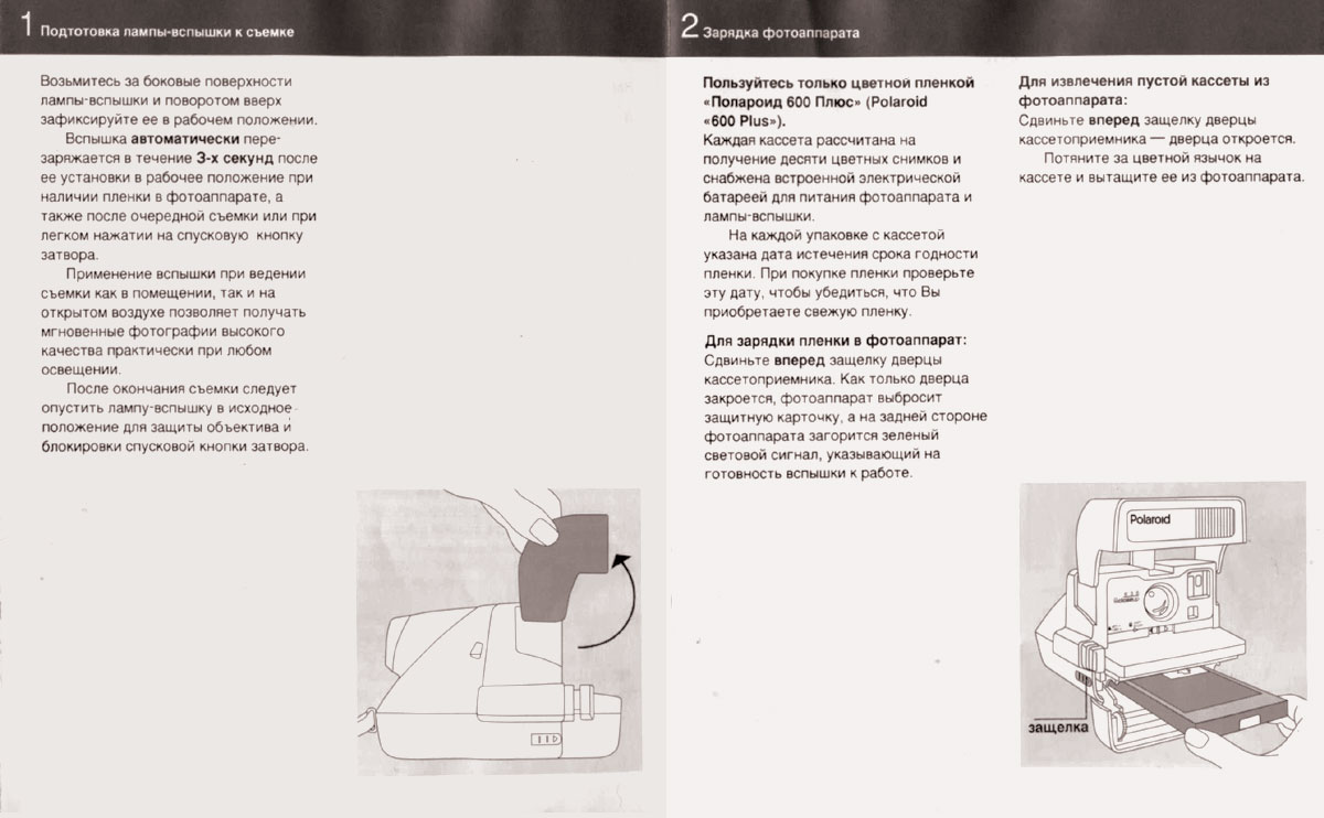
Для зарядки пленки в фотоаппарат: cдвиньте вперед защелку дверцы кассетоприемника. Как только дверца закроется, фотоаппарат выбросит защитную карточку, а на задней стороне фотоаппарата загорится зеленый световой сигнал, указывающий на готовность вспышки к работе.
Для извлечения пустой кассеты из фотоаппарата: cдвиньте вперед защелку дверцы кассетоприемника — дверца откроется. Потяните за цветной язычок на кассете и вытащите ее из фотоаппарата.
Фотосъемка. Подготовка фотоаппарата
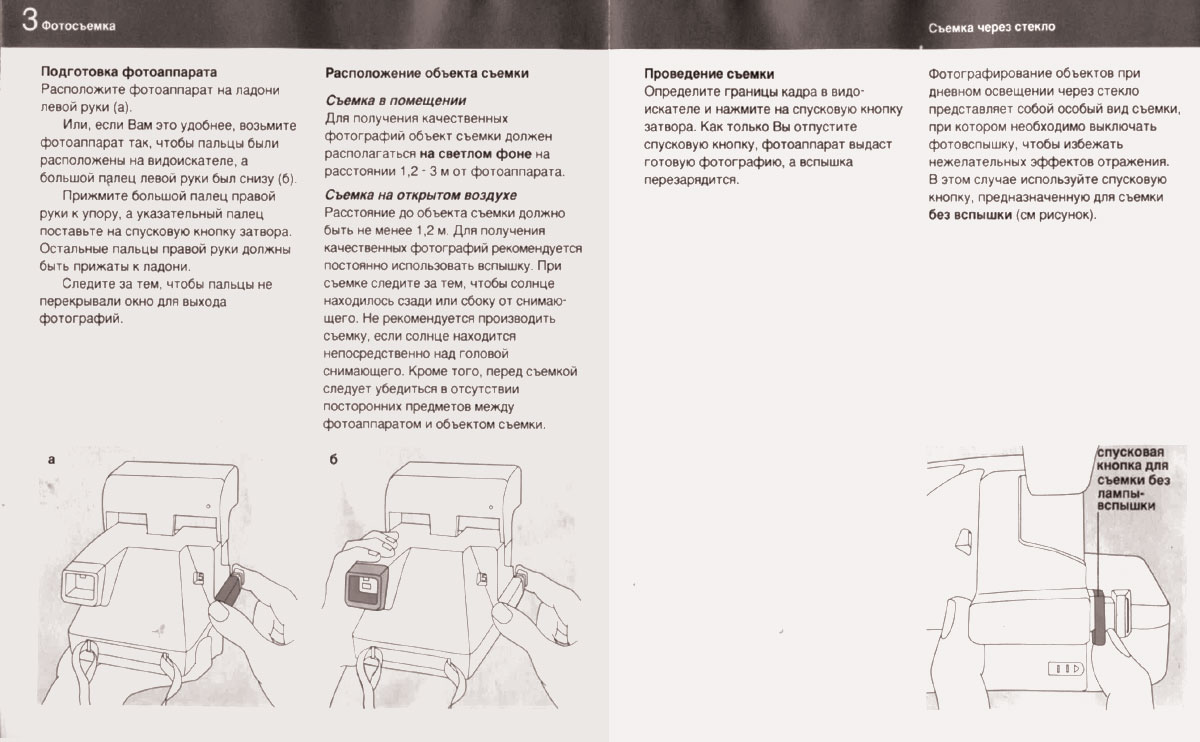
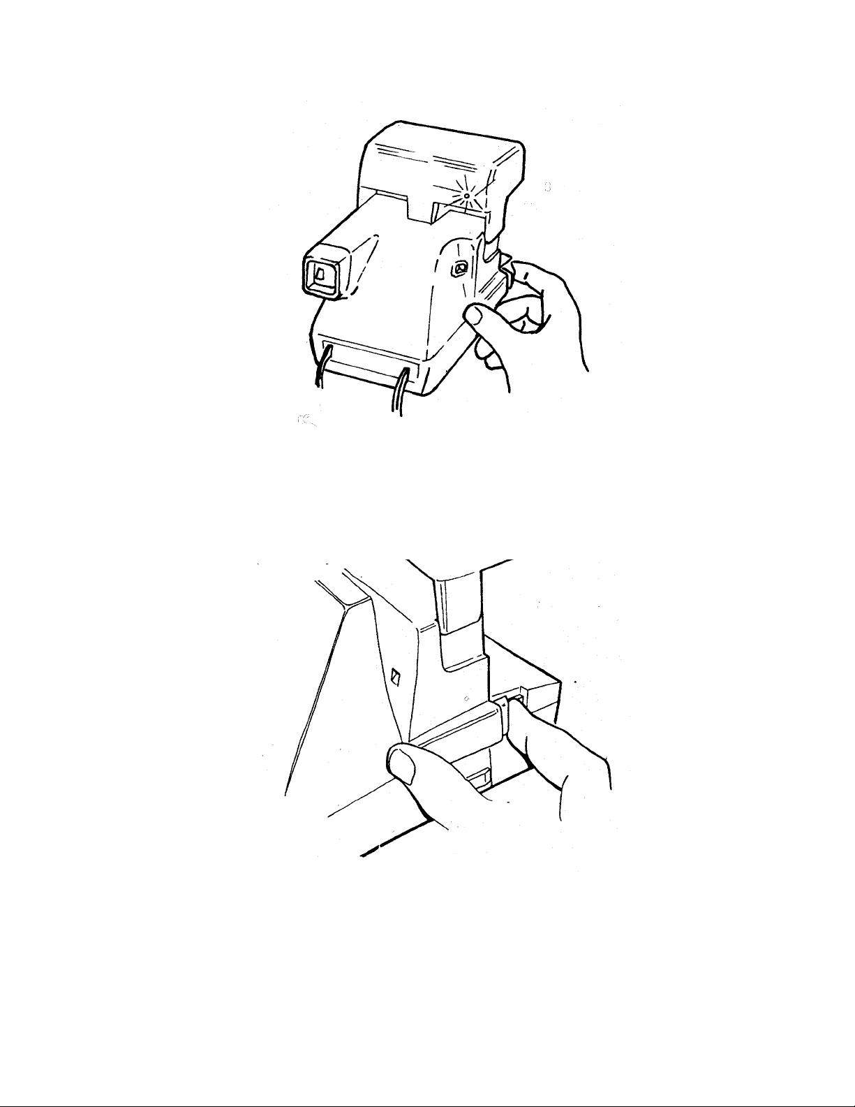
Расположите фотоаппарат на ладони левой руки (а).
Или, если Вам это удобнее, возьмите фотоаппарат так, чтобы пальцы были расположены на видоискателе, а большой палец левой руки был снизу (б).
Прижмите большой палец правой руки к упору, а указательный палец поставьте на спусковую кнопку затвора. Остальные пальцы правой руки должны быть прижаты к ладони.
Следите за тем. чтобы пальцы не перекрывали окно для выхода фотографий.
Расположение объекта съемки
Съемка в помещении: для получения качественных фотографий объект съемки должен располагаться на светлом фоне на расстоянии 1.2 — 3 м от фотоаппарата.
Съемка на открытом воздухе: расстояние до объекта съемки должно быть не менее 1,2 м. Для получения качественных фотографий рекомендуется постоянно использовать вспышку. При съемке следите за тем. чтобы солнце находилось сзади или сбоку от снимающего. Не рекомендуется производить съемку, если солнце находится непосредственно над головой снимающего. Кроме того, перед съемкой следует убедиться в отсутствии посторонних предметов между фотоаппаратом и объектом съемки.
Съемка через стекло: определите границы кадра в видоискателе и нажмите на спусковую кнопку затвора. Как только Вы отпустите спусковую кнопку, фотоаппарат выдаст готовую фотографию, а вспышка перезарядится. Фотографирование объектов при дневном освещении через стекло представляет собой особый вид съемки, при котором необходимо выключать фотовспышку, чтобы избежать нежелательных эффектов отражения. В этом случае используйте спусковую кнопку, предназначенную для съемки без вспышки (см рисунок).
Съемка крупным планом
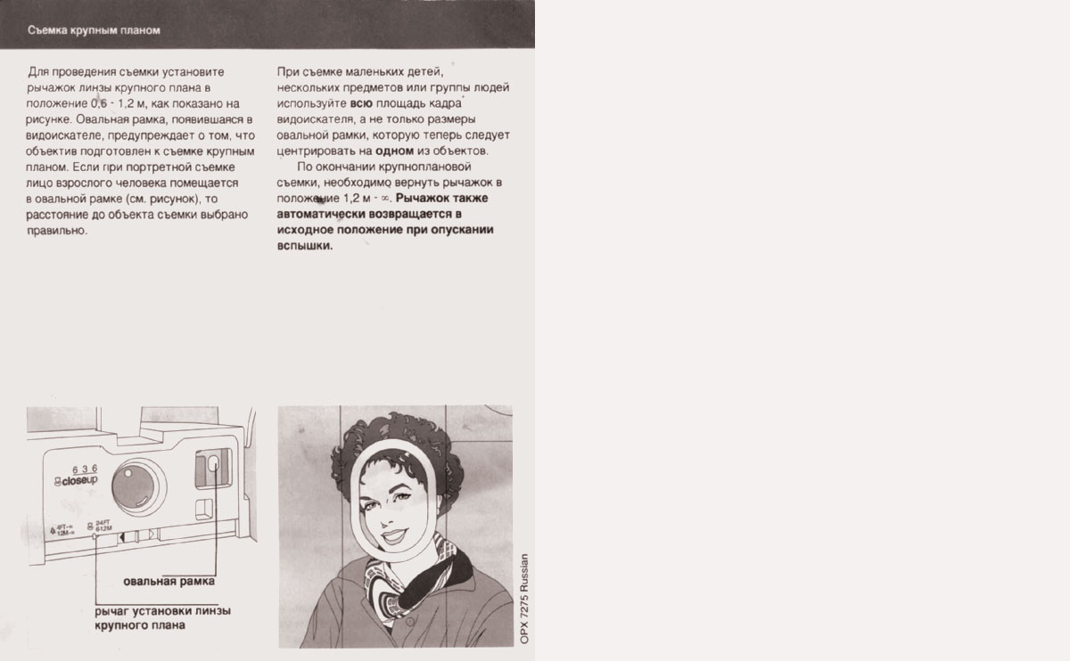
Для проведения съемки установите рычажок линзы крупного плана в положение 0,3 -1.2 м, как показано на рисунке. Овальная рамка, появившаяся в видоискателе, предупреждает о том, что объектив подготовлен к съемке крупным планом. Если при портретной съемке лицо взрослого человека помещается в овальной рамке (см. рисунок), то расстояние до объекта съемки выбрано правильно. При съемке маленьких детей, нескольких предметов или группы людей используйте всю площадь кадра видоискателя, а не только размеры овальной рамки, которую теперь следует центрировать на одном из объектов. По окончании крупноплановой съемки, необходимо вернуть рычажок в положение 1,2 м – 8. Рычажок также автоматически возвращается в исходное положение при опускании вспышки.
Регулятор экспозиции

Этот переключатель используется в случае необходимости проведения повторной съемки с целью корректировки яркости изображения на снимке.
(а) Чтобы получить более светлое изображение на снимке, передвиньте регулятор в сторону белой стрелки
(б) Чтобы получить более темное изображение на снимке, передвиньте регулятор в сторону черной стрелки.
(в) Закончив повторную съемку объекта, верните регулятор в центральное положение
Если регулятор экспозиции не возвращен в центральное положение, в нижней части видоискателя появляется в качестве напоминания двойная белая стрелка
Условия получений качественных фотографии
Во время проявления держите фотографию за широкий край белой рамки и предохраняйте ее от воздействия прямых солнечных лучей.
Температура
При температуре воздуха ниже 13′ С следите за тем. чтобы фотоаппарат и пленка не переохлаждались. Сразу же после съемки уберите проявляющуюся фотографию в теплый карман или другое теплое место и подержите ее там, не сгибая, по крайней мере в течение минуты. Более подробная информация о температуре хранения фотографий содержится на упаковке кассеты.
Объектив
Избегайте прикосновений к объективу. Чтобы удалить пыль и отпечатки пальцев с поверхности объектива, слегка подышите на него и осторожно протрите чистой и мягкой салфеткой. Не допускается использовать жесткие салфетки, предназначенные для протирки стекол очков.
Уход за роликами проявляющего устройства
Загрязнение роликов проявляющего устройства может вызвать появление пятен или полос на фотографиях. Ролики проявляющего устройства находятся за дверцей кассетоприемника. Если необходимо почистить ролики при заряженном аппарате, дверцу следует открывать при неярком освещении. Для чистки роликов применяется влажная неворсистая ткань.
В случае, если фотоаппарат не производит съемку
Проверьте счетчик кадров. При пустой кассете вспышка будет продолжать заряжаться от батареи, но спусковая кнопка работать не будет. Зеленый световой сигнал на задней стороне камеры указывает лишь на то, что вспышка готова к работе.
Рекомендации по качеству фотографии
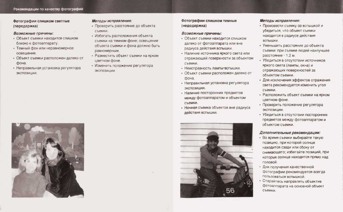
Фотографии слишком светлые (передержка)
Возможные причины:
- Объект съемки находится слишком близко к фотоаппарату.
- Темный фон или неравномерное освещение
- Объект съемки расположен далеко от фона.
- Неправильная установка регулятора экспозиции
Методы исправления:
- Проверить расстояние до объекта съемки.
- Избегать расположения объекта съемки на темном фоне, освещение объекта съемки и фона должно быть равномерным.
- Разместить объект съемки на ярком цветном фоне.
- Изменить положение регулятора экспозиции
Фотографии слишком темные (недодержка)
Возможные причины:
- Объект съемки находится слишком далеко от фотоаппарата или вне радиуса действия вспышки
- Наличие источника яркого света или отражающей поверхности за объектом съемки.
- Неисправность лампы-вспышки.
- Неправильная установка регулятора экспозиции.
- Наличие посторонних предметов между фотоаппаратом и объектом съемки.
- Ночная съемка объектов вне радиуса действия вспышки.
Методы исправления:
- Произвести съемку со вспышкой и убедиться, что объект съемки находится в радиусе действия вспышки.
- Уменьшить расстояние до объекта съемки: при съемке людей наилучшее расстояние 1,2 м.
- Убедиться в отсутствии источников яркого света (лампы, окна) и отражающих поверхностей за объектом съемки
- Для исключения эффектов отражения света рекомендуется изменить угол съемки.
- Расположить объект съемки на ярком цветном фоне.
- Проверить положение регулятора экспозиции.
- Убедиться в отсутствии посторонних предметов между фотоаппаратом и объектом съемки.
Дополнительные рекомендации:
- Во время съемки выбирайте такую позицию, при которой солнце находится сзади или сбоку от снимающего; избегайте позиций, при которых солнце находится прямо над головой.
- Дли получения качественной фотографии рекомендуется всегда пользоваться вспышкой.
- Старайтесь направлять объектив фотоаппарата на основной объект съемки.
Нерезкое (размытое) изображение

Возможные причины:
- Ведение съемки без вспышки в условиях слабой освещенности.
- Недостаточное расстояние до объекта съемки.
- Смещение положения фотоаппарата или объекта съемки во время съемки
Методы исправления:
- При съемке внутри помещения следует всегда применять вспышку. Кроме того, необходимо использовать вспышку при съемке на открытом воздухе в тени, в сумерках и в пасмурную погоду.
- Откорректировать расстояние до объекта съемки в соответствии с рабочим диапазоном вспышки.
- Рекомендуется плавно нажать на спусковую кнопку и держать палец на кнопке до прекращения работы мотора; обеспечить фиксированное положение объекта съемки в момент нажатия спусковой кнопки.
Неполностью проявленное изображение
Возможные причины:
- Повреждение проявляющей капсулы фотографии до зарядки пленки в кассету.
Методы исправления:
- При зарядке аппарата рекомендуется держать кассету аккуратно за края и вводить ее в камеру до отказа.
- Рекомендуется извлекать кассету из упаковочной коробки непосредственно перед использованием
Мастерские по обслуживанию и ремонту
Если вам необходима информация или помощь, а также если ваша камера требует ремонта, обращайтесь, пожалуйста, к поставщику продукции фирмы Попароид или в ближайшее ее представительство.
Гарантийные обязательства
Гарантийный срок эксплуатации фотоаппарата 1 год со дня продажи в розничной торговой сети. При отсутствии даты продажи гарантийный срок исчисляется с даты изготовления по коду, который имеется на каждом фотоаппарате. В течение гарантийного срока бесплатно производится ремонт фотоаппарата или его замена на аналогичный фотоаппарат в установленном порядке.
Настоящая гарантия не распространяется на неисправности фотоаппарата, вызванные небрежным обращением, неправильным хранением или несоблюдением правил эксплуатации. В этих случаях устранение обнаруженных в фотоаппарате неисправностей производится за счет владельца по установленным расценкам. Для производства гарантийного ремонта фотоапларат должен быть возвращен в одну из гарантийных мастерских.
Меры предосторожности
При обращении с фотоаппаратом, как и любым другим устройством с питанием от батарей, необходимо соблюдать меры предосторожности:
1. Выполнять все положения настоящей инструкции
2. Не пользоваться неисправным фотоаппаратом, пока он не будет проверен в специализированной мастерской.
3. Не разбирать фотоаппарат. Во избежание поражения электрическим током обслуживание и ремонт фотоаппарата должны производиться исключительно сотрудниками специализированной мастерской. Неправильная сборка фотоаппарата в случае самостоятельной разборки может вызвать поражение электрическим током при его последующем использовании. Не разрешается погружать фотоаппарат в воду или другие жидкости.
ПРИ ПОЛЬЗОВАНИИ ФОТОАППАРАТОМ POLAROID 636 Close Up СОБЛЮДАЙТЕ, ПОЖАЛУЙСТА, ИНСТРУКЦИИ И РЕКОМЕНДАЦИИ, СОДЕРЖАЩИЕСЯ В НАСТОЯЩЕМ РУКОВОДСТВЕ.
View the manual for the Polaroid 636AF here, for free. This user manual comes under the category photo cameras and has been rated by 1 people with an average of a 7.8. This manual is available in the following languages: English. Do you have a question about the Polaroid 636AF?
Ask your question here
Frequently asked questions
Can’t find the answer to your question in the manual? You may find the answer to your question in the FAQs about the Polaroid 636AF below.
Is the manual of the Polaroid 636AF available in English?
Yes, the manual of the Polaroid 636AF is available in English .
Is your question not listed? Ask your question here
View the manual for the Polaroid 636 here, for free. This manual comes under the category photo cameras and has been rated by 2 people with an average of a 9.1. This manual is available in the following languages: English. Do you have a question about the Polaroid 636 or do you need help?
Ask your question here
Polaroid 636 specifications
Below you will find the product specifications and the manual specifications of the Polaroid 636.
The Polaroid 636 is a compact instant camera that was popular during the 1990s. It features a built-in automatic flash for low-light conditions, making it convenient for indoor or nighttime photography. The camera utilizes Polaroid’s SX-70 film, producing instant prints that develop within minutes. The 636 has a fixed focus lens, which is suitable for capturing subjects at medium distances. The camera also has a simple point-and-shoot design, making it easy for beginners to use.
The Polaroid 636 is known for its iconic square-shaped prints, measuring approximately 3.5 x 4.2 inches. The camera is powered by a built-in battery, eliminating the need for external power sources. The compact size of the 636 makes it ideal for on-the-go photography, allowing users to capture moments instantly without the need for bulky equipment. The camera’s simple operation and instant gratification appeal to those looking for a fun and nostalgic photography experience. Overall, the Polaroid 636 offers a unique and user-friendly way to capture memories in an instant.
General
Frequently Asked Questions
Can’t find the answer to your question in the manual? You may find the answer to your question in the FAQs about the Polaroid 636 below.
Why does the flash not work when I take a photo with my Polaroid 636?
Ensure that the flash is turned on by sliding the flash switch located on the side of the camera to the ‘ON’ position. Also, make sure that the flash ready indicator light on the front of the camera is illuminated before taking a picture.
How can I adjust the focus on my Polaroid 636 camera?
To get the focus right, turn the lens barrel located on the camera’s front until the subject you want is sharp in the viewfinder. The barrel has marks showing the distance range for clear focus.
Why are my pictures coming out too dark or too bright with the Polaroid 636?
Make sure ya have selected the right exposure settin’ based on the lightin’ conditions. The camera offers different exposure options, such as ‘Normal’ for average lightin’, ‘Bright’ for well-lit scenes, and ‘Dark’ for low light situations. Adjust the exposure switch on top of the camera accordin’ly.
How do I load the film into my Polaroid 636?
Open the camera back by pressing the latch located on the side. Insert the film pack into the film compartment, ensuring that the yellow marks on the film align with the yellow marks in the camera. Close the camera back securely until it clicks into place.
What should I do if the film doesn’t eject from my Polaroid 636 after taking a photo?
At times, ya might run into a snag with the film ejecting in the Polaroid 636. Give the darkslide a gentle tug (that’s the black tab on the front) until it extends all the way out. Once it stops, slide it back in and see if the film comes out right. If it’s still playing up, give the camera a reboot by takin’ out and putting back the film pack.
Is the manual of the Polaroid 636 available in English?
Yes, the manual of the Polaroid 636 is available in English .
Is your question not listed? Ask your question here
Repair Manual
636/636AF Instant Camera
December 1995
Americas Business Center
Technical Services
201 Burlington Road
Bedford MA 01730
TEL: 1.781.386.5309
FAX: 1.781.386.5988

[This p age intentio nally blank]

Model 636 Camera Service Manual
CONTENTS
Section Page
1 General Description 1
2 Sequence of Operation 3
3 Theory of Operation 13
4 Disassembly & Reassembly 36
5 Troubleshooting 75
6 Testing with the Star Tester,
Camera Adjustments and Tester
Calibration 85
7 Testing with the B-600 Tester,
Camera Adjustments and Tester
Calibration 106
PARTS CATALOG: Separate document.
See Polaroid Model 636 CAMERA PARTS CATALOG,
January 1994 for part names, numbers and exploded views.
i

LIST OF ILLUSTRATIONS
Figure Description Page
(SECTION 1 Model 636 Description)
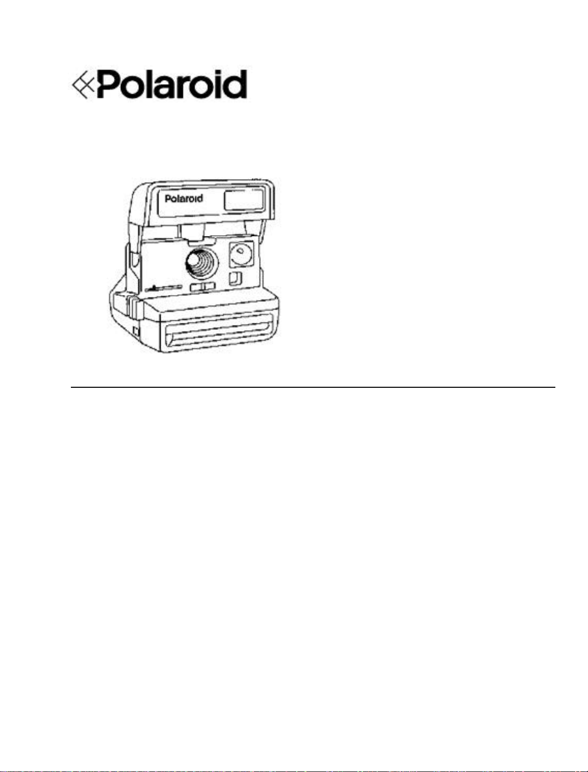
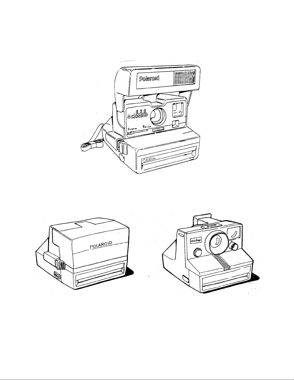
— 636 Camera 1
(SECTION 2 Sequence of Operation)
— Flash charging, fire & exposure switches 3
— Stro be charging 3
— Stro be ready sequence 4
— Exposure sequence 4
— Exposure sequence: clock & photocell 5
— Fill flash sequenc e 5
— Flash qu ench, shutter c losing 6
— Moto r drive of pick, counter, S5 actuat or 6
— Low ambient exposure sequence 7
— Subject near/far determination 7
— “ “ “ 8
— Low light near exposure contr ol 8
— Moto r drive of pick, counter, S5 actuat or 9
— Sub ject far determin atio n 9
— Low light far exposure sequence 10
— Moto r drive of pick, counter, S5 actuat or 10
— Non-flash exposure control 11
— Camera Operating/Exposure Sequence Diagram 12
(SECTION 3 Theory of Operation)
— 636 Camera 13
— 600 film pack 14,15
— 636 Flash 16
— Flash charging 17
— Flash qu enching 18
— Three flash picture conditions 20
— F lash contr ol met ho ds 21
— High ambie nt , fill fla sh mode 22
— Photo cell light measurement 23
— Low ambient flash exposure 24
— Subject near/far determination 25-28
— IR light measurement 28-33
— Exposures without flash 33
— Camera inhibits 34-35
(SECTION 4 Disassembly and Reass embly)
— Strobe components 37
1 Removing S trobe Cover 38
2 Discharging Strobe capacitor 38
3 Removing Lower Housing 39
4 Removing Flex 39
ii

Figure Description Page
5 Removing Flashtube, Flash Shield, Insulator 40
6 Unsoldering Flashtube wire leads 40
7 Removing PC Board & Plunger 41
— Apron Disassembly compon en t s 42
8 Removing Apron from Body 43
9 Removing Pane l/Front P late 43
10 Dis assemb ling Close Up Len s & Tr im Button 44
11 Reassembling Close Up Lens 45
12 Replacing Shuttle 45
— Body Disassemb ly comp o n en t s 46
13 Re moving Cone from Body 47
14 Re mov ing Strap A ssembly 47
15 Removing Pack Spring, Tripod Nut if present 48
16 Removing Eye Cup/Retainer 48
— Shutter Disassemb ly comp o n en t s 49
17 Re moving Viewfinder Hou s ing 50
18 Re mov ing Opening Blade Spr ing & Trim Slide 50
19 Removing Ambient Cal Disc, IR Cal Wedge, IR
Lens Filter & Ambient Lens Filter 51
20 Re moving Lens Mounting Plate 51
21 Removing Inertia, Walking Beam, Shutter
Latch & Shutter Blades 52
22 Dis assemb ling Ine rtia & Walking Beam 52
23 Removing Flex from Contact Support Block,
Motor and Wire Block 53
24 Removing Base Block from Cone 53
25 Removing Flex from Base Block 54
26 Re moving So lenoid from Base Block 54
27 Re placing Solenoid in Base Block 55
28 Replacing Flex on the Base Block 55
29 Remounting Base Block on Co ne 56
30 Reconnecting Flex to Contact Support Block,
Motor and Wire Block Assy 56
31 Replacing Shutter Blades 57
32 Re assemb ling Ine rtia, Walking Beam & S pr ing 57
33 Replacing Walking Beam/Inertia Assy 58
34 Replacing Shutter Latch 58
35 Replacing Lens Mounting Plate 59
36 Re placing Trim Slide 59
37 Replacing Photometrics on Lens Mtg Plate 60
38 Replacing Opening Blade Spring 60
iii

Figure Description Page
— Drive Assembly components 61
39 Re moving par ts from Gear Drive C over 62
40 Releasing Springs and Drive Cover detents 63
41 Re moving Gear Drive C over 64
42 Removing parts from Gear Drive 64
43 Removing Counter, Gears & Pick 65
44 Removing S1 Slider and S5 Actuator 65
45 Replacing Actuator and Slider Assy 66
46 Verifyin g S lider-Switch contact relationship 66
47 Gear placement guide 67
48 Replacing Door Pawl and Spring 67
49 Replacing Counter 68
50 Replacing Pick & Return Spring 68
51 Re placing the Timing Gear 69
52 Setting Counter and Pawl Springs 69
53 Reconnecting wiring to Contacts 70
54 Removing Spread System from Door 71
(SECTION 6 Camera Testing with t h e St a r Tester)
1 Graywall set up 87
2 I n stalling modified Strob e Fixture 12657B 88
3 Aligning Camera on Horn with Tester window 89
4 I nstalling riser s un der le veling le gs 90
5 Test setup and Horn Riser position 91
6 Star Tester Controls & Indicators 94
7 Setup for 636 Graywall Test 98
8 Removing 636 Front Plate 100
9 Adjusting Blade Spring 100
10 Replacing Front Plate w/modified Front Plate 101
11 Adjustin g Ambient Calibration Disc 101
12 Adjusting IR Calibration Wedge 102
(SECTION 7 Camera Testing with the B-600 Tester)
1 B-600 Tester and Model B Light Source 108
2 Camera on Horn, ready for test ing 111
3 Removing Front Plate/Lens Panel 115
4 Adjusting Opening Blade Spring 115
5 Replacing Front Plate w/modified Front Plate 116
6 Adjusting IR Calibration Wedge 116
7 Adjusting Ambient Calibration Disc 117
iv
SECTION 1 — MODEL 636 CAMERA GENERAL DESCRIP T ION
The Model 636 OneStep/CloseUp Camera is an evolutionary, reliable, low-cost design in the
Polaroid “600” family of integr al stro be, fixe d focus har dbod y cameras. I t makes exten sive use o f
the 640 Camera technology and has many derivative characteristics of the 630 and 635 Camera
designs as well. The 636 offers automatic exposure control, fixed focus and rapid strobe recharge.
Model 636 was introduced in worldwide and U.S. markets in 1992 and 1993, and offers users the
following features:
* Close-up lens for subjects 2 — 4 ft. (0.6 — 1.2m) from Camera. An oval frame outline visible in
the Viewfinder helps position subject correctly.
* Depth of field 4 ft. (1.2 m) to infinity.
* Built-in, fold down, integral quench SPAR Strobe with 2 to 10-ft.(0.6 to 3.0 m) range, in
swing-up housing. Strobe charges auto matically in 4 sec. when erected. Green st r obe-ready
LED in re ar of h ousing; remains ON for abo ut 30 sec.
* Electronic logic for fill- flash in o utdoor brightness, in appr ox imate propo rtions of 75% amb ient
light and 25% s trobe fill.
* Uses 10-picture Polaroid 600 (ASA 600) color film.
1

* Non-flash butt on allows pictu res to be taken without strobe firing (e. g., through glass window).
* Lighten/Darken (trim) control for adjusting exposure + or — 3/4 sto p. When in L or D position,
double arrows are visible in Viewfinder as reminder to user .
* Expo sure control utilizin g both ambien t and IR ligh t measurement. Fla sh e xpos ur e con trol via
IR quench full dissipation SPAR strobe.
* Picture counter shows number of exposures remaining (counts down).
* “Talking Camera” version plays pre-record ed message just before shutter opening, to encour-
age s ubjects to s mile.
* Adju stable neck strap and on s ome mo de ls, trip od soc ket.
SPECIAL NOTE: 636 AF AUTOFOCUS CAMERA:
Model 636 AF Autofocus Camera, from a service standpoint, is simila r to the 636 OneStep/Close
Up only in outward appearance.
As an extension of the 636 Camera line, the 636 AF uses a slightly modified version of the Impulse
shutter and a repackaged version of the Joshua electronics and software. It uses wink autofocus
from two feet to infinity, a rapid recharge strobe with a range of 10 feet, and has a maximum
shutter aperture of f/12.
In addition to more t han two dozen unique parts, the 636 AF camera uses a combination of parts
from the 636, the Impulse Shutter and Joshua electronics.
* * * * * *
For more information, please refer to:
NPI 600AM #95-44, dated March 27, 1995
636 AF CAMERA CUSTOMER SERVICE INFORMATION MANUAL
MARCH 1995
MODEL 636 AUTOFOCUS CAMERA PARTS CATALOG
MARCH 1995
2
SECTION 2 — MODEL 636 SEQUENCE OF OPERATION
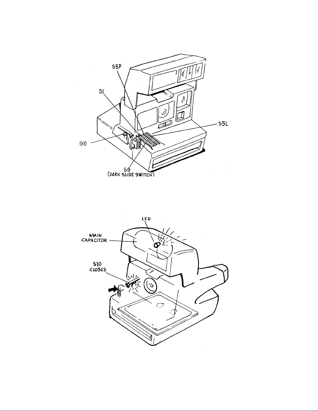
1. Shown here is the location of the switches which regulate flash charging, flash fire and
exposure. We will now run t h rough a flas h exposure sequen ce.
2. Lightly pressing the exposure button closes the S10 contacts, charging the strobe main
capacitor.
3
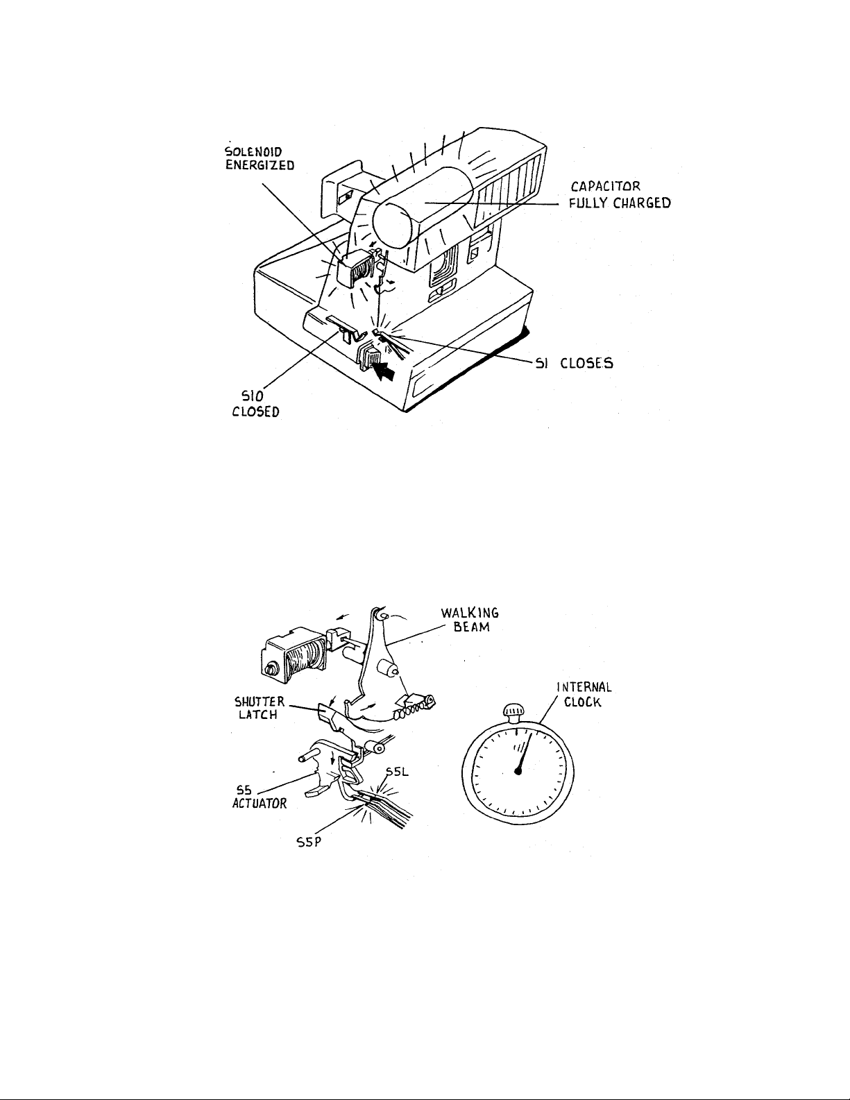
3. Within five seconds the green LED at the rear of the strobe comes on, indicating that the
main capacitor is fully charged. The picture taker may now press in the exposure butto n
fully. This closes S1 and S10 remains closed. Closing S1 energizes the solenoid which
pulls in slight ly.
4. As the solenoid pulls in, it releases the walking beam from the shut ter latch . The springloaded S5 actuato r dr ops down, closing the S5P and S5L contacts. S5L star ts an internal
clock. The camera electronics signal the solenoid to deenergize.
4
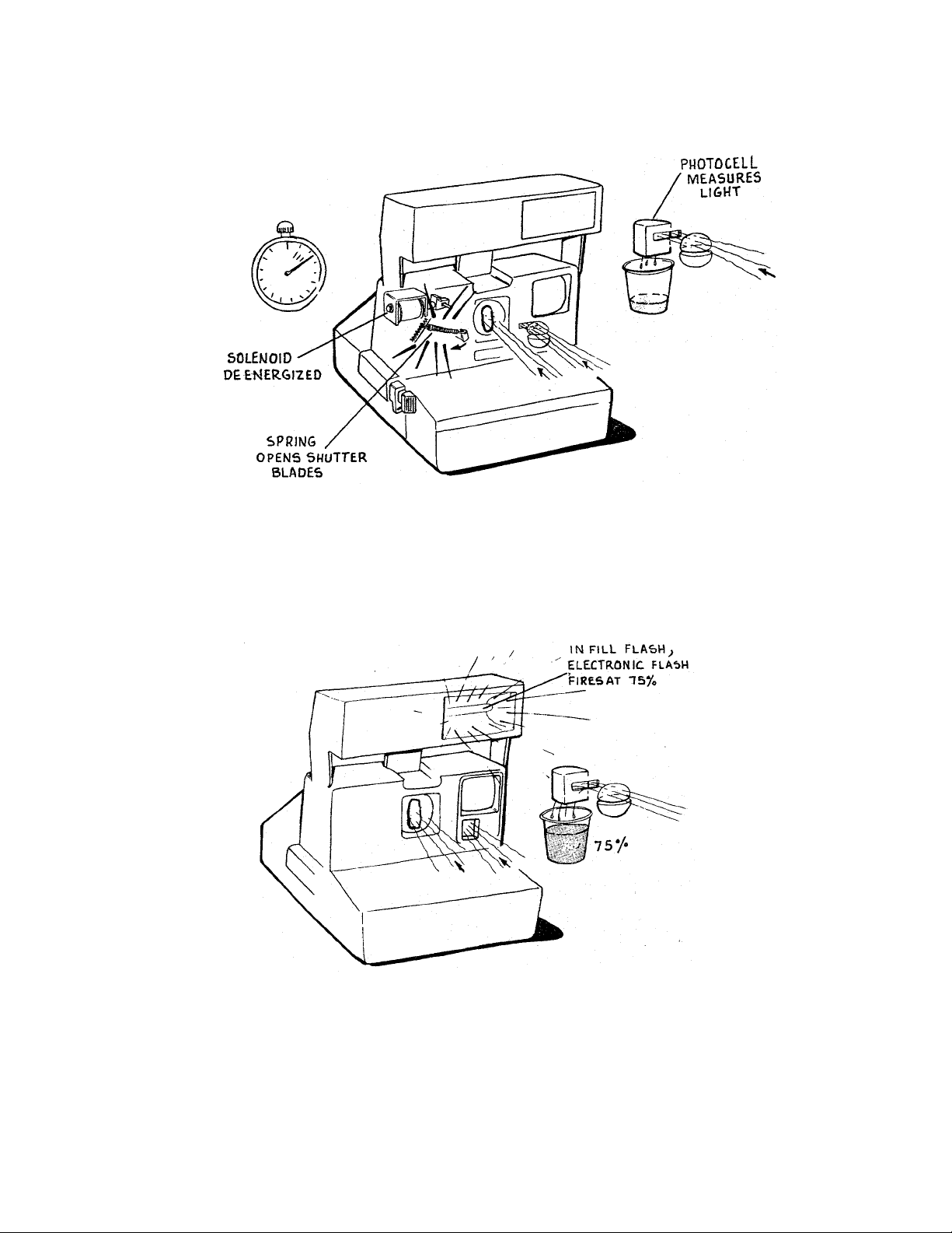
5. With the solenoid deenergized and the walking beam free of the shutter latch, springaction opens the shutter blades. The internal clock is running and the photocell starts to
measure light.
6. In a fill- flash expo sure, when t h e pho toc ell sees 75% of the ligh t n eeded for a proper
exposure, it signals the flash to fire. The flash provides the remaining 25% of the
necessary light. Note that in a fill-fla sh exposure, the ph otocell alwa ys be ats the internal
clock in ordering flash fire.
5
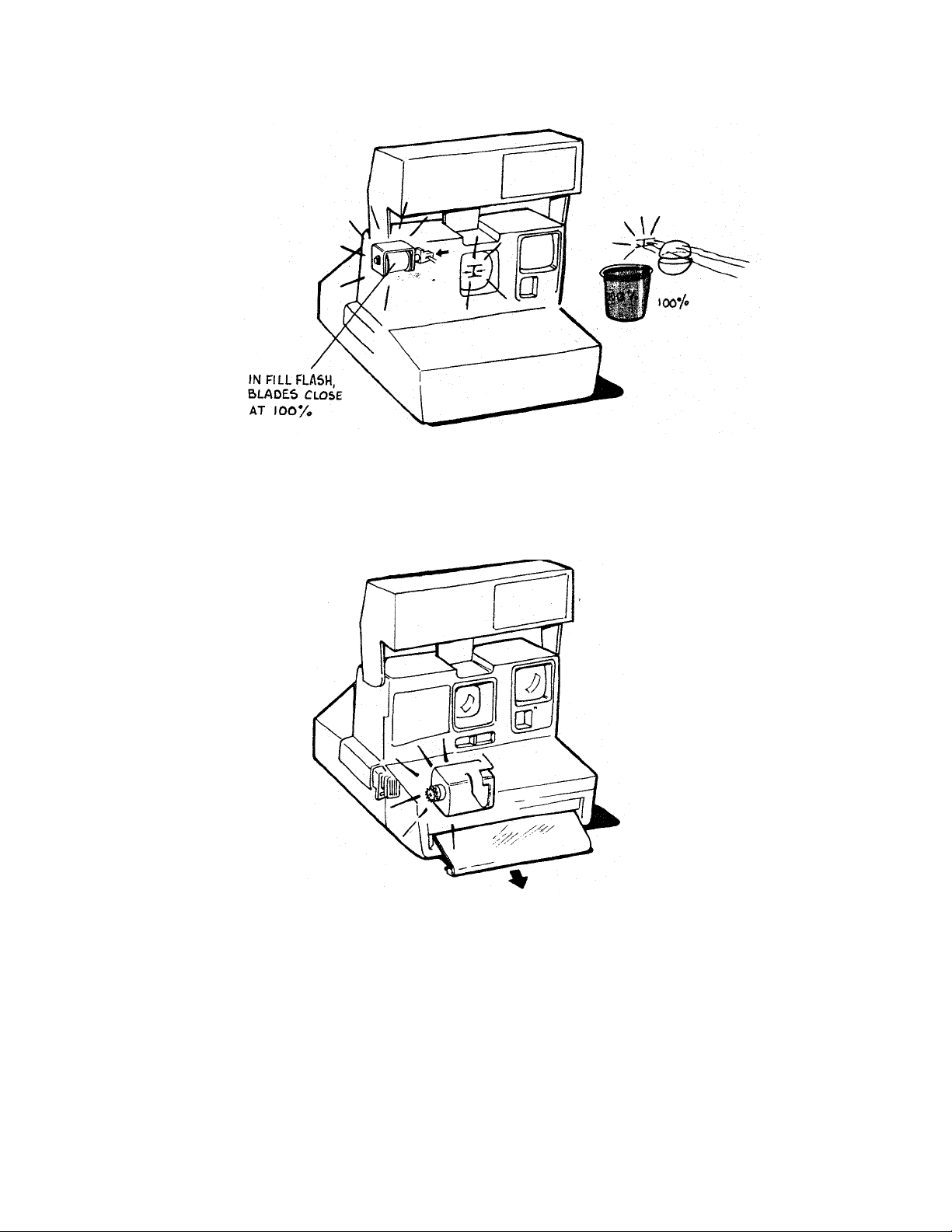
7. When the photocell sees 100% of the light needed for the exposure, the camera electronics
orders t he flash to quench and the solenoid to energize. The solenoid then pulls the blades
closed.
8. After the blades close, t h e moto r is tur ned o n, activ ating a gear d rive syst em similar to the
system in the On eStep. The timin g gear:
advances the pick
indexes the counter
brings the S5 actuator back to its original position.
Th e solenoid deenergizes and th e sh utter syst em is again la tche d c los ed , e nding the fillflash sequence.
6
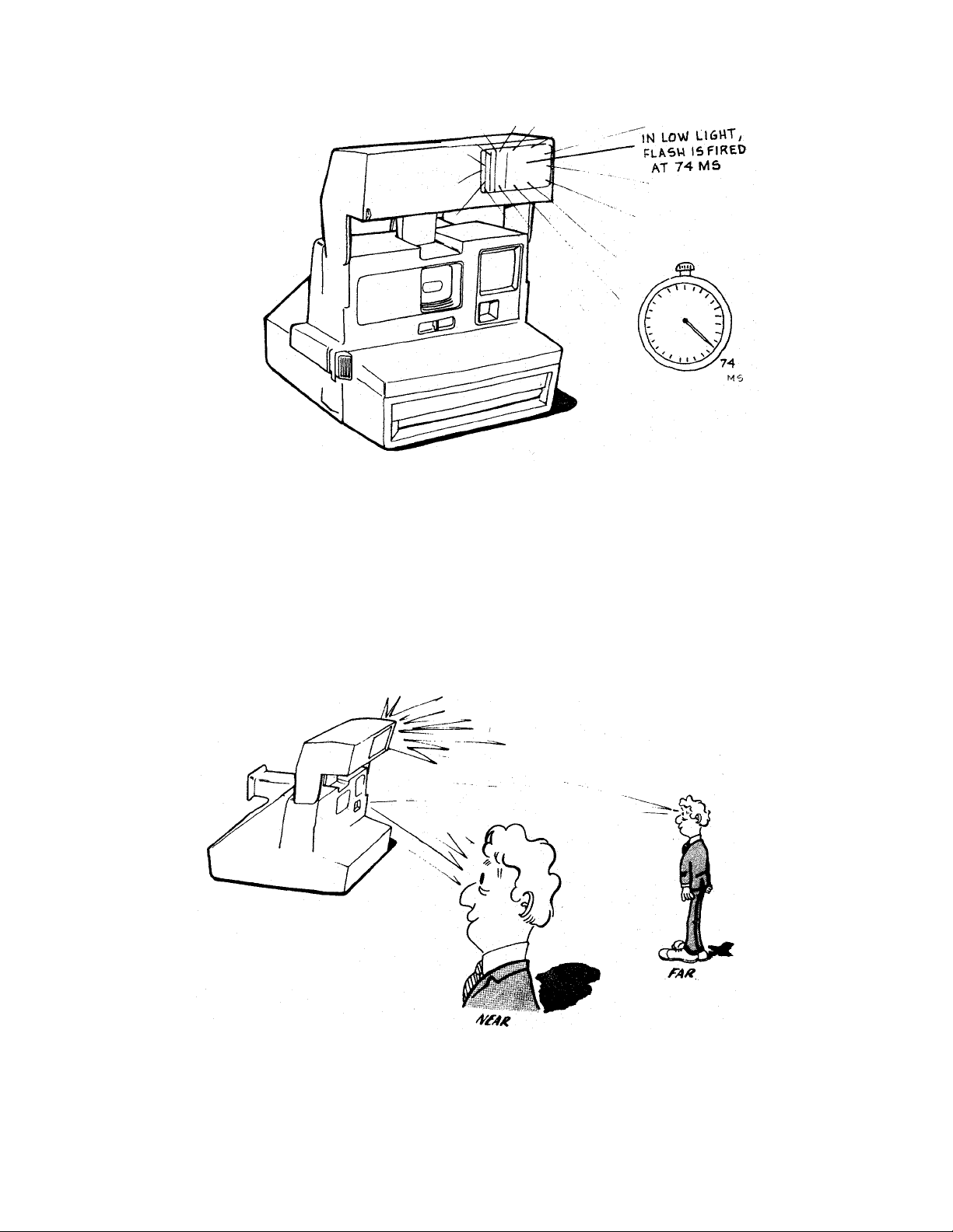
9. Th e sequen ce for low-amb ient conditions b egins id entic ally to th e fill-flash sequenc e. The
flash is charged via S10 and the shutter blades open the same way. However, the flash is
fired by the internal clock reaching 74 ms, rather than by the photocell light measurement.
This happens because there is relatively little light passing through to the photocell.
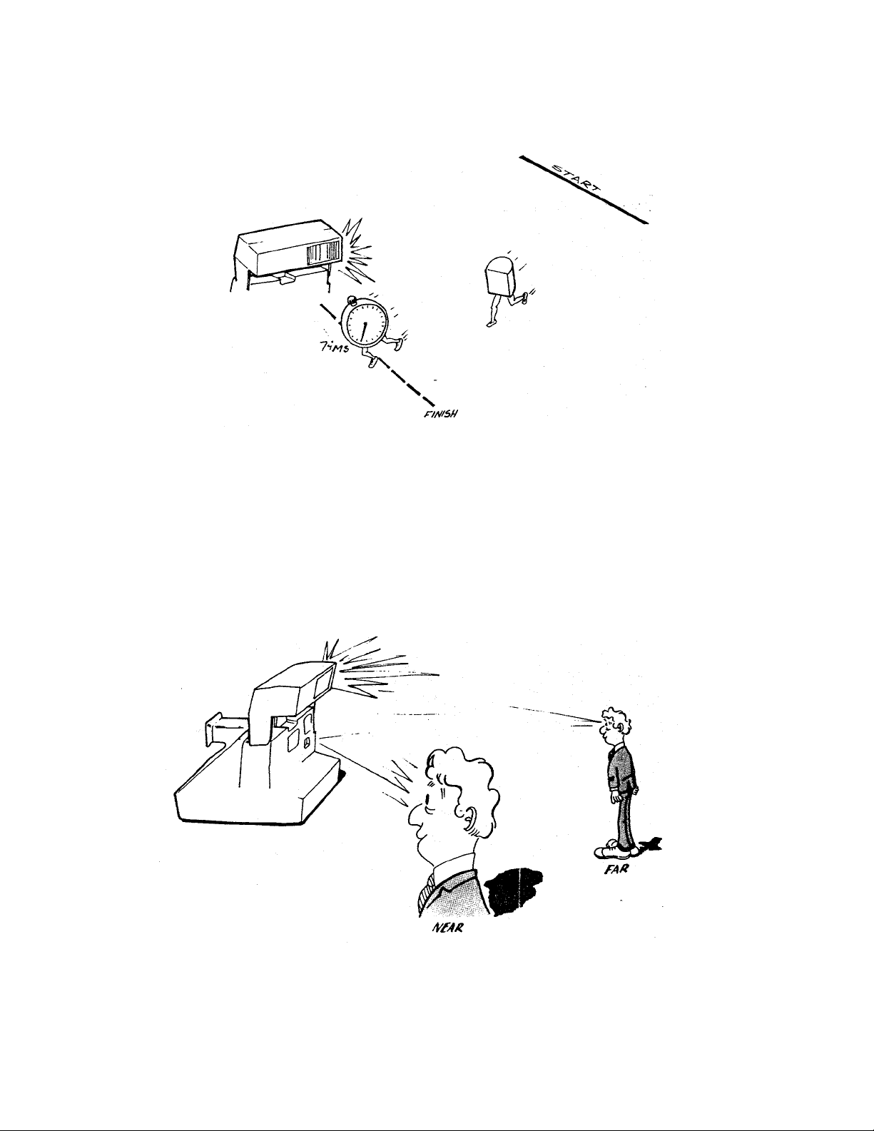
10. Next, the camera logic asks whether the subject is NEAR or FAR. This information is
needed to pro per ly set the electronics for low ambient pictures.
7
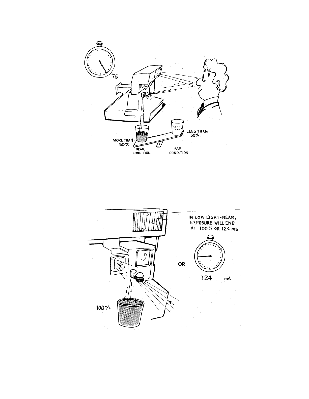
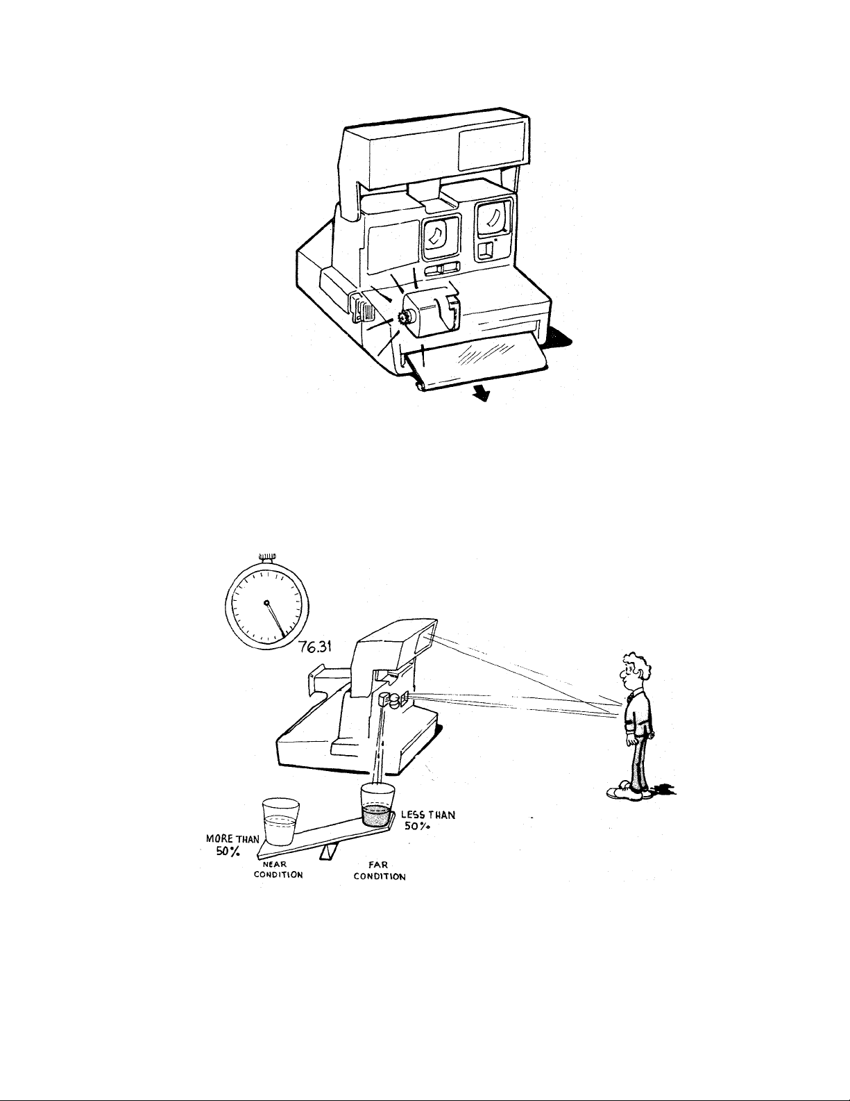
11. The camera determines whether the subject is NEAR or FAR by measuring the amount of
light reflected b ack to th e ph otocell 2 milliseconds after th e flash has fired (76 ms into the
exposure sequence). If the measurement is more than 50% of the tot al needed for a proper
exposure, the camera decides the subject is NEAR. If the subject is NEAR, the electronics
sets the clock to time-out at 124 ms.
12. In a low-light NEAR picture, the blades open partially so that the photocell is measuring
infrared light through the infrared filter. The flash is quenched and the shutter blades
closed either when the photocell sees 100% of the light needed for a proper exposure o r
when the internal clock reaches 124 ms.
8
13. After the blades close, th e moto r is tur n ed on. The timin g g ear a dvances th e pick, indexes
the counter, and brings the S5 actuator back to its o r iginal position. The shutter system
is latched closed, ending the low ambient NEAR sequence.
14. If the light measured 2 milliseconds after the flash has fired is less th an 50% of t he total
needed for a proper exposure, the camera decides the subject is FAR.
9
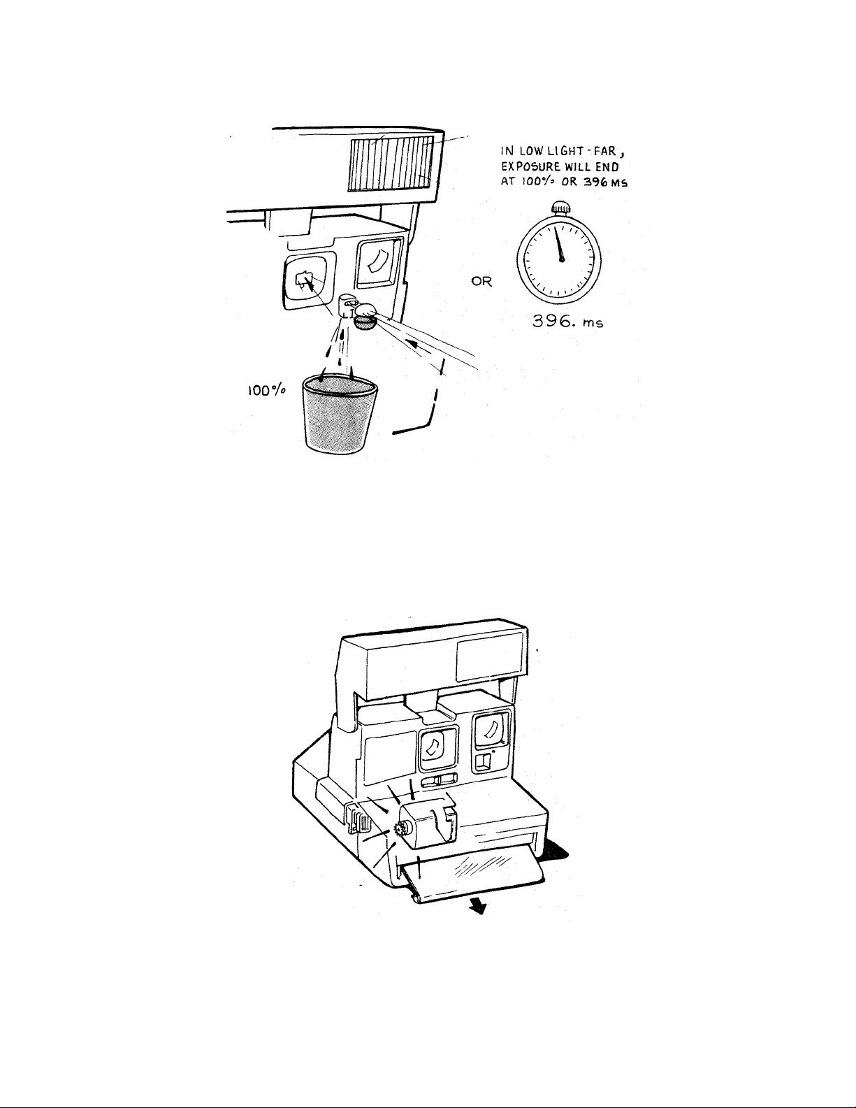
15. In a low-light FAR picture, the blades open fully and the photocell sees scene light
through the photopic filter. When 100% of the necessary light is seen or when the internal
clock reaches 396 ms, the flash is quenched and the shutter blades close.
16. After the blades close, th e moto r is tur n ed on. The timin g g ear a dvances th e pick, indexes
the counter, and brings the S5 actuator back to its o r iginal position. The shutter system is
latched closed, ending the low-ambient FAR sequence.
10
17. For a non-flash picture (through a window), t he exposure is start ed by pressing S1 only.
The end-exposure command is given either when the photocell sees 100% of the necessary
light for a proper exposure or when the internal clock reaches 396 ms.
11
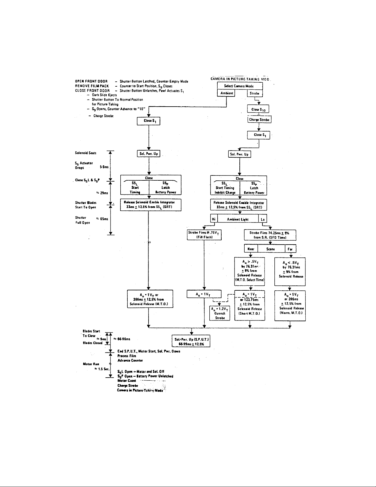
Camera Operating/Exposure Sequence Diagram
12
SECTION 3 — MODEL 636 THEORY OF OPERATION
1. This is the Model 636 Camera which is one of a new line of 600 cameras.
2. The Model 636 shares many of the features of the 635 and 640 Cameras. Among these are:
Fixed Fo cus Lens , Electron ic S h utter, Film Shade , L ighte n/Dark en Co nt rol, Empty Pack
Lockout, Film Co unte r, Carrying Strap and a Fill Flash Capabilit y.
13
3. One of the major differences between the Model 636 and the OneStep is the type of film it
uses. Like all of the 600 line, the 636 uses a new film format. The film has a speed of 6 O0
ASA.
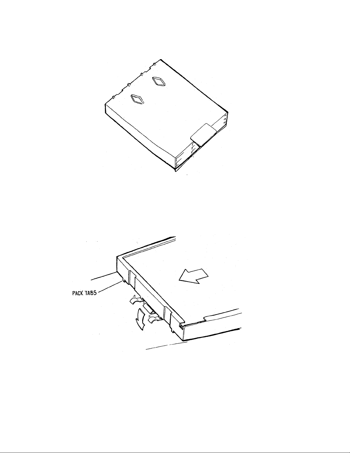
4. On the inner edge of the 600 film pack is a set of molded plastic tabs whic h interface with
the pack spring in the camera. The two middle tabs press down the ramps of the pack
sp ring, allowing the film pack to s lide over th e stop for ins er tion in to the camera. On o lder
style SX-70 packs there are no tabs. As a result, the pack is prevented from being inserted
into a 600 line camera by the pack spring stop.
14
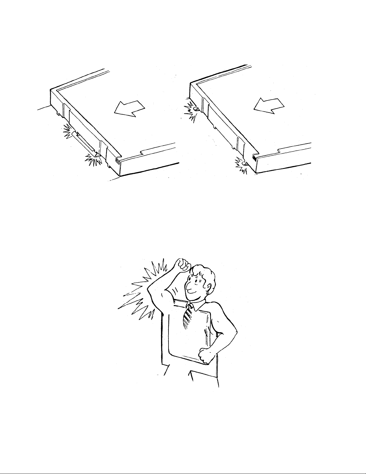
5. On the other hand, a 600 film pack can n ot be ins er ted int o an S X- 70 style camera sin ce th e
tabs on the pack are held back by the older style pack springs.
6. The battery in the 600 film pack h as a hig her capacity than the conv entional SX- 70 battery.
It pro vides power for t he shutt er solenoid, the motor and for t he built-in electronic flash.
15
7. When you open the camera, you can see another o bvious difference between the Model 636
and the One Step — a built-in electronic flash. The flash is designed to be used for all
pictures, both indoors and outdoors.
8. The electronic flash features a rapid charge time of about 5 seconds. For o utdoo r pictures,
t h e flash is used to provide a proportio n al fill- flash to e liminate objectionable sha dows.
Indoors, the flash provides contro lled light for scenes within a 4 to 10-foot range.
16
9. The flash is charged by lightly pressing the camera exposure button. The exposure mode is
electronically inhibited until the flash is fully charged. When the green LED comes on, a
picture can be taken by pressing the exposure button in all the way.
10. An alternate way to charge the flash is to lightly press the exposure butto n. The button can
t h en be r eleased. Afte r the gree n LED h as co me on the flash will stay fully c harged for
approximately one minute. When the exposure is ready to be made, the exposure button is
presse d in fully, in o n e mot ion .
17
11. The built-in flash is an electronic quench-type flash. It can provide a full output of about
340 zonal-lumen seconds (ZLS) to illuminate a scene or it can be shut down early to
provide less light to the scene. The way the camera decides to provide full or part ial light
o utput will b e discussed later.
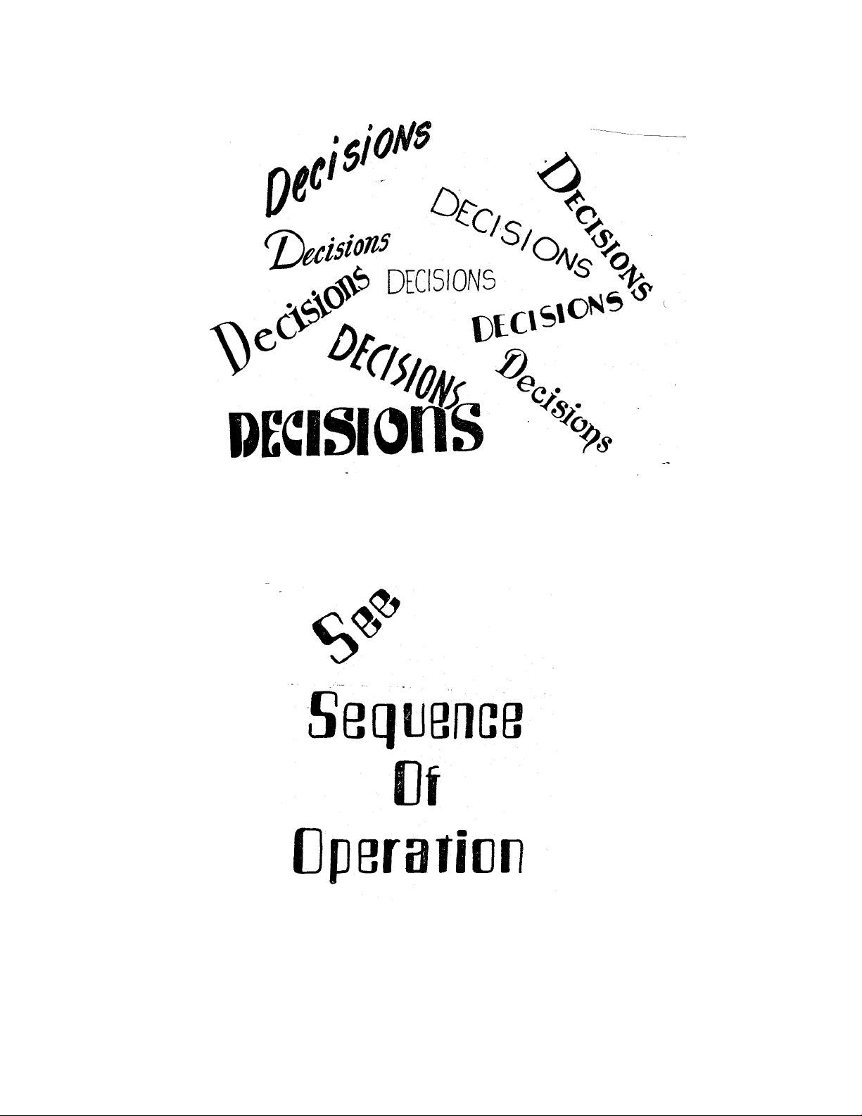
12. Whether or not the flash provides full output , the main capacitor delivers the same amount
of energy. Therefore, if the flash is ordered to shut down early, some means must be found
to dissipate the remaining energy in the circuit. This remaining energy is diverted through a
thyristor (TH1) on the strobe board.
18
13. Now, let’s t alk about the way the camera logic decides when to fire the flash and how much
light it ne e ds fro m the flash before it q uenches it.
14. Refer to the Sequence of Operation section for a description of the order in which all of the
events in an exposure cycle occur. (The operating sequence is also shown in diagram form,
at the end of Section 2.)
19
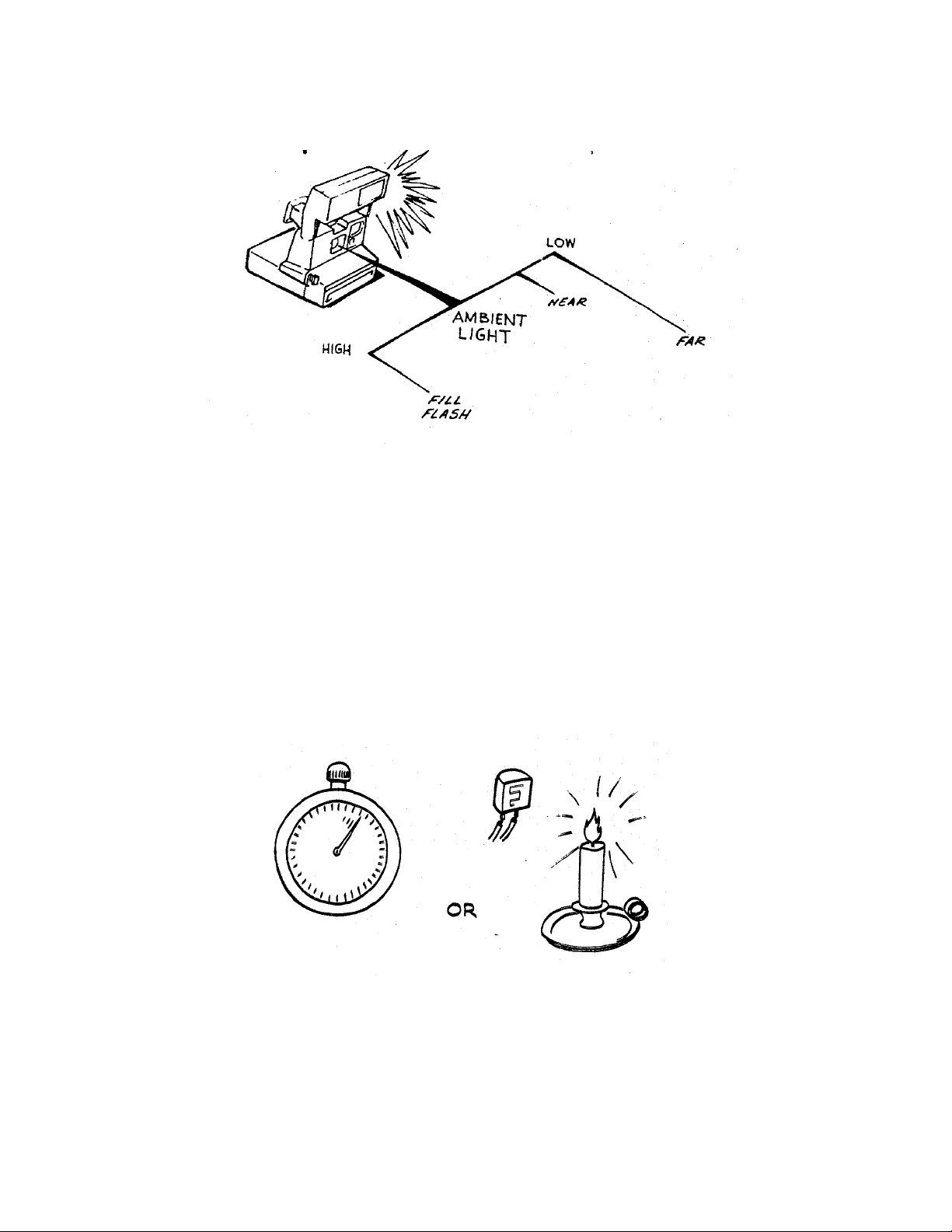
15. There are t hree different conditions in which a flash picture can be taken:
1 — In high ambient light.
2 — In low ambient light with the subject near the camera.
3 — In low ambient light with the subject far from the camera.
16. Basically, the Model 636 uses either a light measurement alone to fire and shut down the
flash, or a combination of light measurement and time measurement to fire and shut down
the flash. The method used depends upon scene brightness.
20
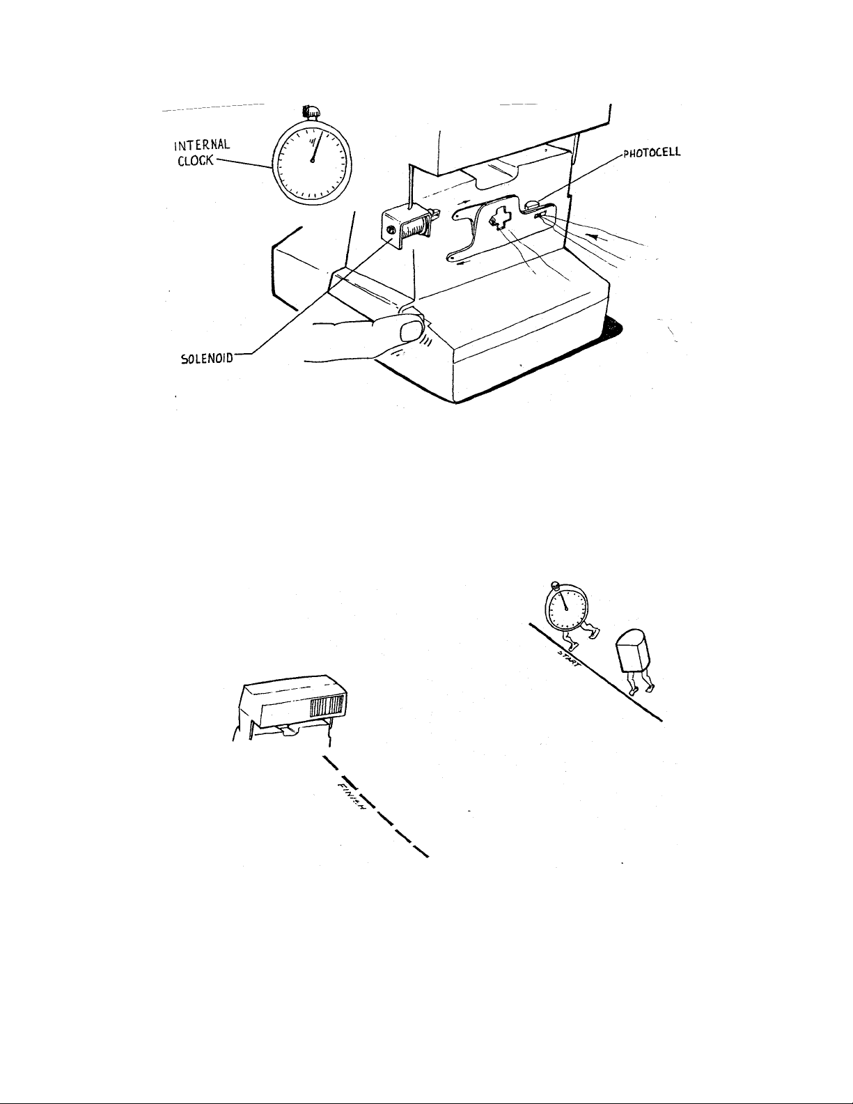
17. After the flash is charged and the exposure button is pressed all the way in, three things
happ en s imultan eously wh ich decide how the flash is going to be con trolled:
1 — The solenoid releases the shutter blades and they start to open;
2 — The photocell starts t o measure scene light;
3 — An internal clock in the camera logic is started.
18. From this point, there is a race between the internal clock and the photocell to decide which
is g oin g to contr ol the flash. Either the internal cloc k will time-out before the p h otocell
mea sure s a pre- determined amount of light or vice versa. W hicheve r occurs firs t will fire the
flas h .
21
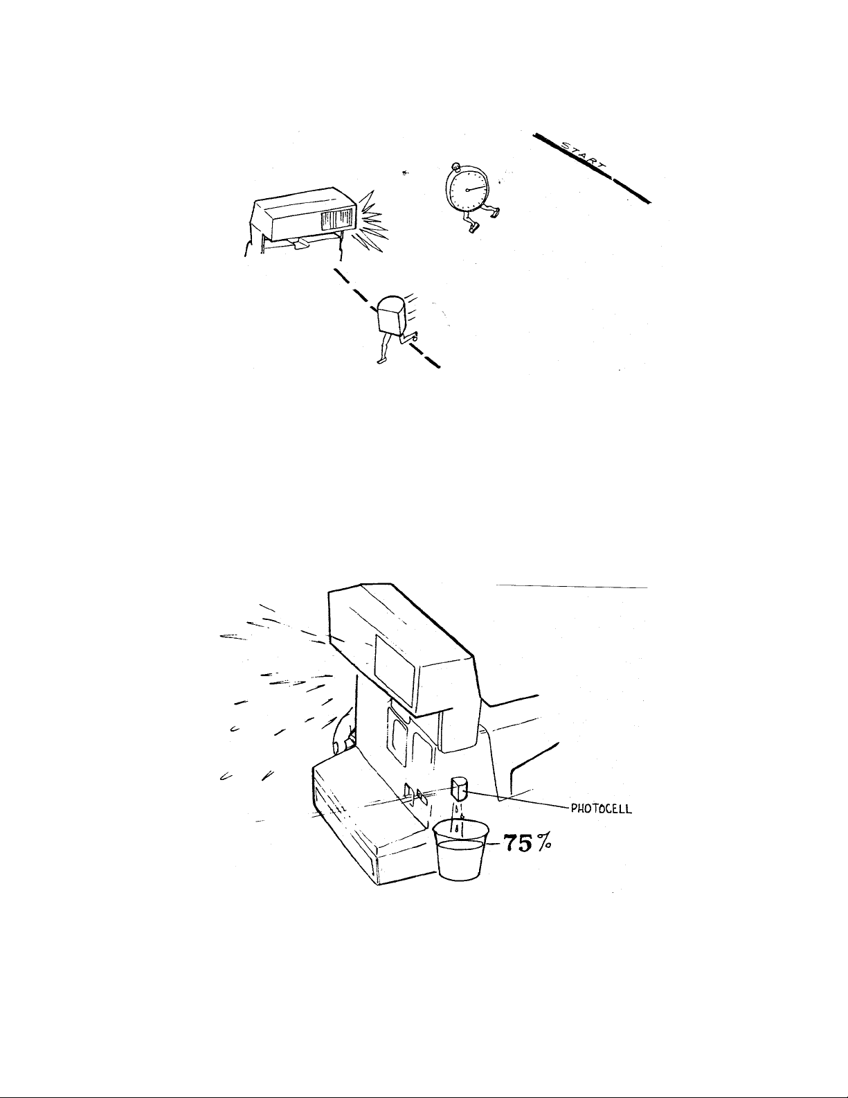
19. Now, let’s go back to the three conditions in which a flash picture can be taken. The first is
in high ambient light. In this condition, there is so much scene light available that the
photocell always wins the race to fire the flash. This is the Fill F lash mode of operation.
20. In th e high ambient or Fill Flash mode, the photoc ell measur es scene light. When it sees
75% of the total light required for a proper exposure, the photocell fires the flash.
22
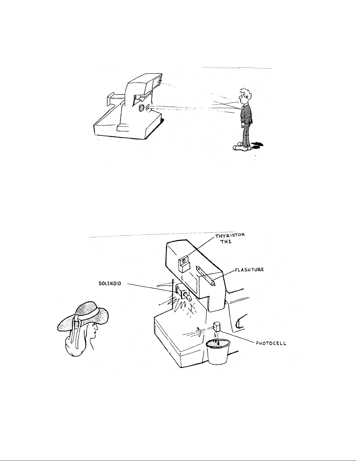
21. At t his po int , the blade s are still o pen an d the expo sure is be in g ma de. The photocell
continues mea s uring light w hich now include s the light bounc ing ba c k fro m the flash. Next,
the camera must decide when to shut down the flash and when to close the shutter blades.
22. In th e high ambient (Fill F lash ) mod e, th e pho toc ell make s the decision to s hut do wn the
flash and close the shutter blades. It do es this when it sees the remaining 25% of the light
required for a proper exposure. (This light is provided by the flash.) The camera logic
signals the flash to quench and commands the solenoid to close the blades.
23
23. The next condition in which a flash exposure can be made is in a low ambient condition
(low light leve l, ou tdoo r scenes and all in doo r s cenes ). In t his c on dition, th er e is so lit tle
light that the clock beats the phot ocell in the race to fire the flash. When the clock reaches
74 millise cond s (ms), the flas h is fired.
24. Two milliseconds after flash fire, a very importan t question is asked by the camer a logic: Is
the subject near or far? The answer is needed to properly set the clock for time-out.
24

25. The question is answered by measuring the amount of light seen by the photocell two
millise conds after flash fire .
26. If the measurement is equal to o r more than 50% of the light needed for a proper exposure,
the camera senses subject is NEAR. If the measurement is less than 50% of the light needed
for a proper exposur e, the camera senses that the subject is FAR.
25

27. For NEAR subjects the logic instructs the clock to stop the exposure at 124 ms after the
blades open. For FAR sub jects t he clo ck will time-out at 396 ms to stop the exposure.
28. However, the ending of the exposure is also subject to the photo cell light measurement. In
oth er words, for a Low Ambie nt NE A R or FAR picture, ther e is st ill a race between the
photocell and the clock to shut down the flash and close the blades.
26

29. In low amb ient N EAR conditio ns, the flash will s hut do wn and th e blades clo se either w hen
the photocell has seen 100% of the light necessary for a proper exposure or when the clock
times-out at 124 ms.
30. In low amb ient FA R conditions, the flash will shut down and t he blad es clo se eithe r w hen
the photocell has seen 100% of the light necessary for a proper exposure or when the clock
times-out at 396 ms.
27

31. The different clock settings for Low Ambient conditions are called the DUAL TIME-OUT
SYSTEM. T hey allow long time-outs for distant, low-light scenes such as a sunset or an
auditor ium shot, or limit the len gth of the expo sure for clos e- in sc ene s to minimize ca mer a
or subject motion.
32. So far we’ve talked about the photo cell measuring scene light to cont rol the exposure, but
we haven’t mentioned the most significant part o f the light measurement system: Infrared
Sensing.
28

33. In earlier cameras where a photocell was used to contr ol the exposure, the photo cell could
be fooled into giving a reading which did not result in a good picture.
34. This was especially true of flash pictures taken of subjects close to the camera. Light-
colored clothing would reflect too much light to t he phot ocell causing it to st op the
exposure too soon.
29

35. On th e other hand , dark clot hing would foo l the p h otoc ell into timing out a long ex posure,
since relatively little light was reflected back. This would result in a washed-out face.
36. To overcome this problem, the Model 636 uses a photocell with a two-part filter in front of
it, called a Dynamic Infrared Photometer system. The top half of the filter passes visible
light which the human eye can see. This light is used to time exposures for non-flash,
fill-flash, a nd low -lig ht , d istant scene flash pictures. T he top filter is a photopic filter.
Th e botto m h alf of the filter passes infra red lig h t whic h is inv isible to the hu man e ye, b ut
which the film can see. This light is used to time exp osures fo r fla sh p ictures in low light
where the subject is near the camera. The bottom filter is called the infrared filter.
30

37. Now you may be wondering why infrared measurements greatly reduce over- or under-
exposures in close-up flash pictures.
38. This chart shows the light spectrum. In the infrared region of the spectrum, a strange
phenomenon occurs. The light reflected off just about all materials is equal. Therefore, the
light passing through the infrared filter is balanced, preventing the photocell from being
fo oled by contr asting le v els of light or dark subject matt er .
31

39. For Fill Fla sh pictu re s, th e sh utter bla de s o pe n as shown here . The blades are set s o only
visible light passes through the firs t photo pic aper ture to th e photocell. T h us, for Fill Flash,
exposure shutdown is based on the measurement of visible light only.
40. In a low light NEAR shot, t he blades travel farther. During blade travel a very small
amount of visible light passes thro ugh t he first photopic aperture. The blades move to the
position shown, the stro be fires and a larger amount of infrared light passes through t he
infrared aperture to the photo cell. Exposure shutdown is dependent upon the combination
o f an extremely limited amount of v isible light a dded to the larger amoun t of infra re d lig ht
(or on the clock time-out).
32

41. For low light FAR pictures, the blades travel even farther. First, there is a very small
amount of light passed through the first photopic aperture. Next, a very small amount of
light passes through the infrared apertu re. Finally, the blades open fully and a large amount
of visible light passes through the second photop ic aperture. The exposure shutdown is
dependent on the measurement of this combination of light (or on clock time-out).
42. The flash may be bypassed on those rare occasions where it is not desired. This is pretty
much limited to takin g p ictures in daylight thro ugh a wind ow. In th is condition, th e flash
can be prevented from firing by pressing only the back part of the exposure button.
Exposure shutdown is determined by the photocell seeing 100% of the light required for a
proper expo sure or by the internal cloc k timing o ut at 396 ms.
33

43. The dark slide cycle is the same as in Pronto! type cameras. When a fresh pack is loaded
and the front door closed, S1 and S9 are closed and the solenoid energized. The S5 actuator
drops, closing S5L and S5P, tur ning on the motor. The dark slide is ejected and the counter
set to 10. The slider is cammed back by the counter, op ening S1 and S9. The rotation of
t h e timing gear lifts t h e S 5 actuator, o pe n ing S5L and S 5P . The camer a is n ow ready for the
exposure cycle.
44. During an exposure cycle, the camera electronics prevents the flash from being recharged.
Also, once the flash is charged, S10 must be closed along with S1 to fire the flash. You
cannot release S10 and press only S1 to fire the flash.
34

NO S1
45. There are two mechanical inhibits. When the counter reaches its blank setting, S1 is
prevented from closing. This is the same as the empty pack lockout feature o n Pronto!
cameras.
46. Finally, when the camera is in the folded position, S10 is mechanically locked open by a tab
on the flash housing. This prevents the flash from being charged.
35

SECTION 4 — MODEL 636 DISASSEM BLY AND REASSEMBLY
Tools needed
Dump Probe P/N 11604
Universal Flex Remover Tool P/N 12601
Strobe Housing Removal Tool P/N 12633-2
Viewfinder Panel Remover P/N 12552-3
Contact Removal Tool P/N 12536
3/32″ diam. dowel pin (for Shutter Blade reassy)
Exacto knife with No. 11 blade
Soldering aid (“greenstick”) P/N 94168
Finger c ots or lintless cotton gloves
Needleno se pli ers
Tweezers and dental pick
Disassembly Note
No screws or t hreaded fasteners are used in the 636 Camera: most housings and piece parts of
sub-assemblies are held in position by detents, spring catches or tangs which engage bosses or
cut out s in c orr espondin g ma ting par ts. Careful “s pr ing apart” t ech niques will fr ee most parts of the
636.
Flex connecting tabs are held in their solderless contacts by internal spring contact pressure. S afe,
easy removal of the flex is done by inserting the appropriate size leg of Universal Tool 12601 into
the connector. T his releases the grip of the internal contacts and allows the flex to be pulled out
together with the removal tool.
Contents of this Section Page
Strobe Disassembly 37
Strobe Reassembly 41
Apron Disassembly 42
Close Up Lens Disassembly 44
Close Up L ens Reassembly 45
Body Disa ssembly 46
Body Reas sembly 48
Shutter Disassembly 49
Shutter Reassembly 55
Drive Disassembly 61
Drive Rea ssembly 66
Door/Spread Sys. Disassembly 71
Reas semb ly co mpletion 72
Note: Reassembly instruct ions are listed in the contents above, only if they include specific,
detailed steps (in contrast to simply replacing parts removed).
36

Strobe Disassembly
37

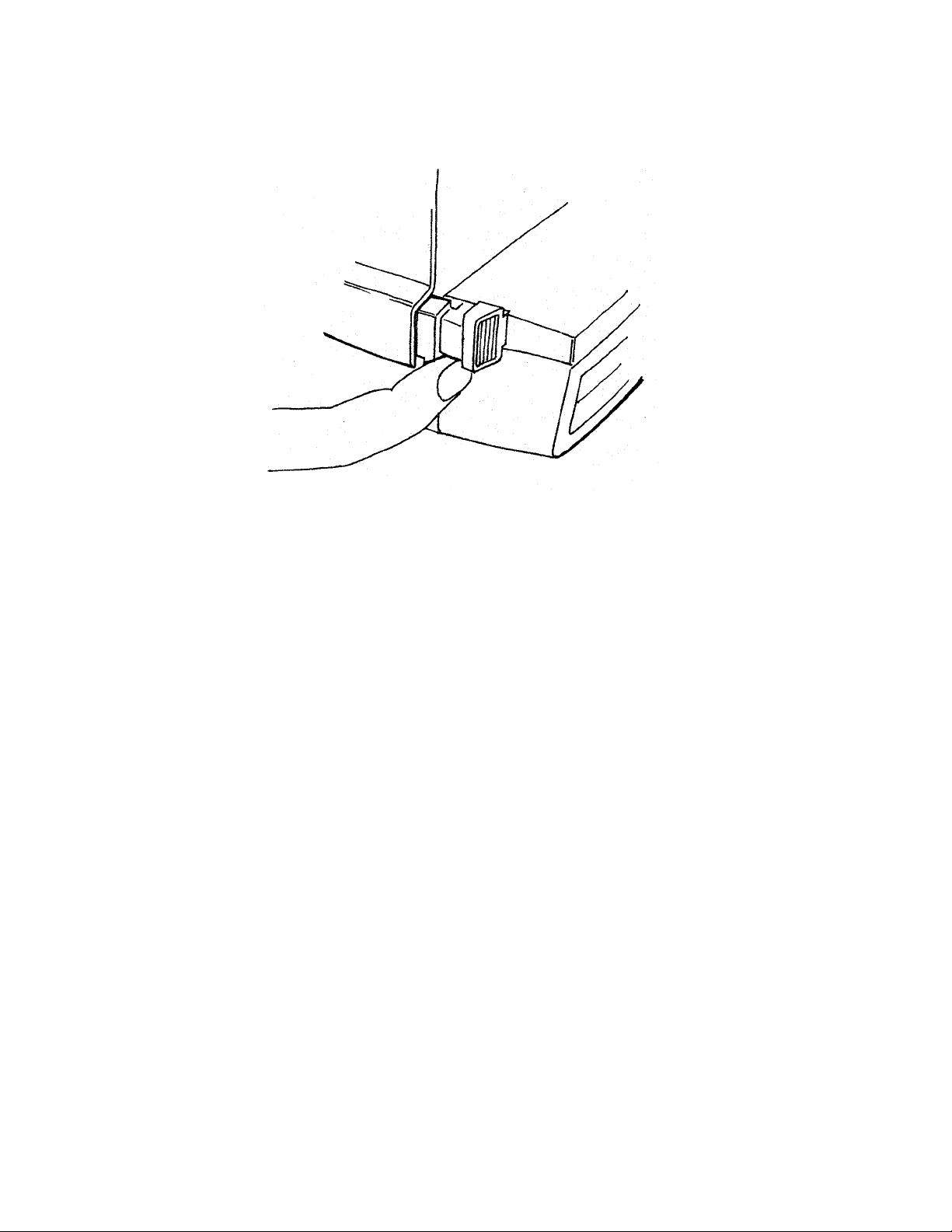
1. Remove Strobe Cover using removal tool 12633. Insert too l in hole on right side
unde rside of Housing and t ilt b ottom of t ool to the rig ht (C CW) t o release molded
catch inside cover (A in Fig. 1). Repeat process on left side, tilting bottom of tool to
the le ft. Lift off Cove r.
Fig. 1 Removing Strobe Co ver
2. Discharge Strobe Capacitor by holding Dump Probe 11604 on Capacitor terminals
for 5 — 10 seconds (Fig. 2).
CAUTION: SHOCK HAZARD! Dump capacitor BEFORE proceeding with disassem-
bly, to avoid painful shock from charged capacitor.
Fig. 2 Discharging Strobe Capacitor with Dump Probe
38

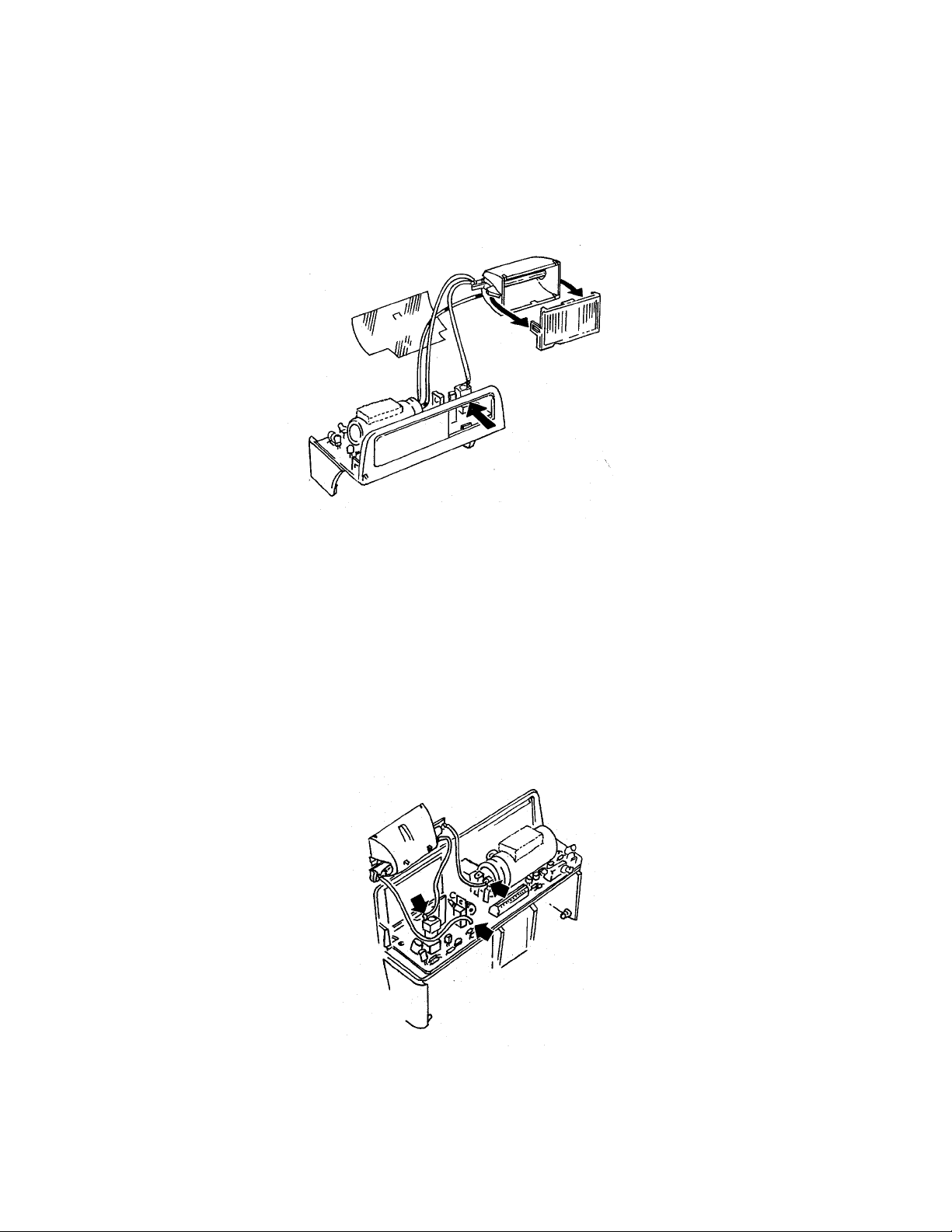
3. With Strobe tilted downward at a 45-degree angle, remove Lower Housing
Assembly using a sold er ing aid tool (greenstick). Care fully spr ing ou t sides as
shown in F ig. 3 (Flex remains c on n ected to L ower Housin g) .
Fig. 3 Removing Lower Housing
4. Remove two Flex leads from PC Board by inserting appropriate-size fingers of
Universal Flex Tool 12601 into Board connecto r s and pulling Flex out (F ig. 4).
Fig. 4 Removing Flex from Lower Housing
39
5. Remove Flashtube Assembly from the Lower Housing by gently pushing in along
top edge of Flash Shield (Fig. 5). Remove Insulator, and unsnap catches on ends of
Flash Shield to re mov e it from Flash tube A ssembly.
Fig . 5 Remov in g Flashtube Assembly, F lash Shield and Insulato r
6. If it is necessary to remove the Flashtube itself, unsolder the three leads from the
Capacitor, PC Board and Trigger Coil (Fig. 6).
Fig. 6 Removing Flashtube by unsoldering wire leads
40
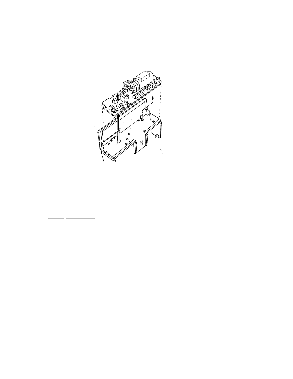
7. Re mov e the PC Board b y lifting it straight up off the molded pos t on the Lower
Housing (Fig. 7), being careful not to lose the small S10 Plunger from the base of
the Lower Housing. Set Plunger aside.
Fig. 7 Removing PC Board & Flashtube Assembly & Plunger
Strobe Reassembly
Replace the parts removed in the preceding Steps 1 — 7, in this order:
Flash Shie ld
Plung er in hole in Lower Housing
PC Board onto two post s in Lower Housing
Insulator
Flashtu be Assembly into Lower Housin g
Insert the Lower Housing pivots into the openings in the Apron.
Reconnect the Flex to the PC Board.
Replace the Cover by inserting the tab and snapping the Cover into place on the Lower
Housing.
41

Apron Disassembly
42

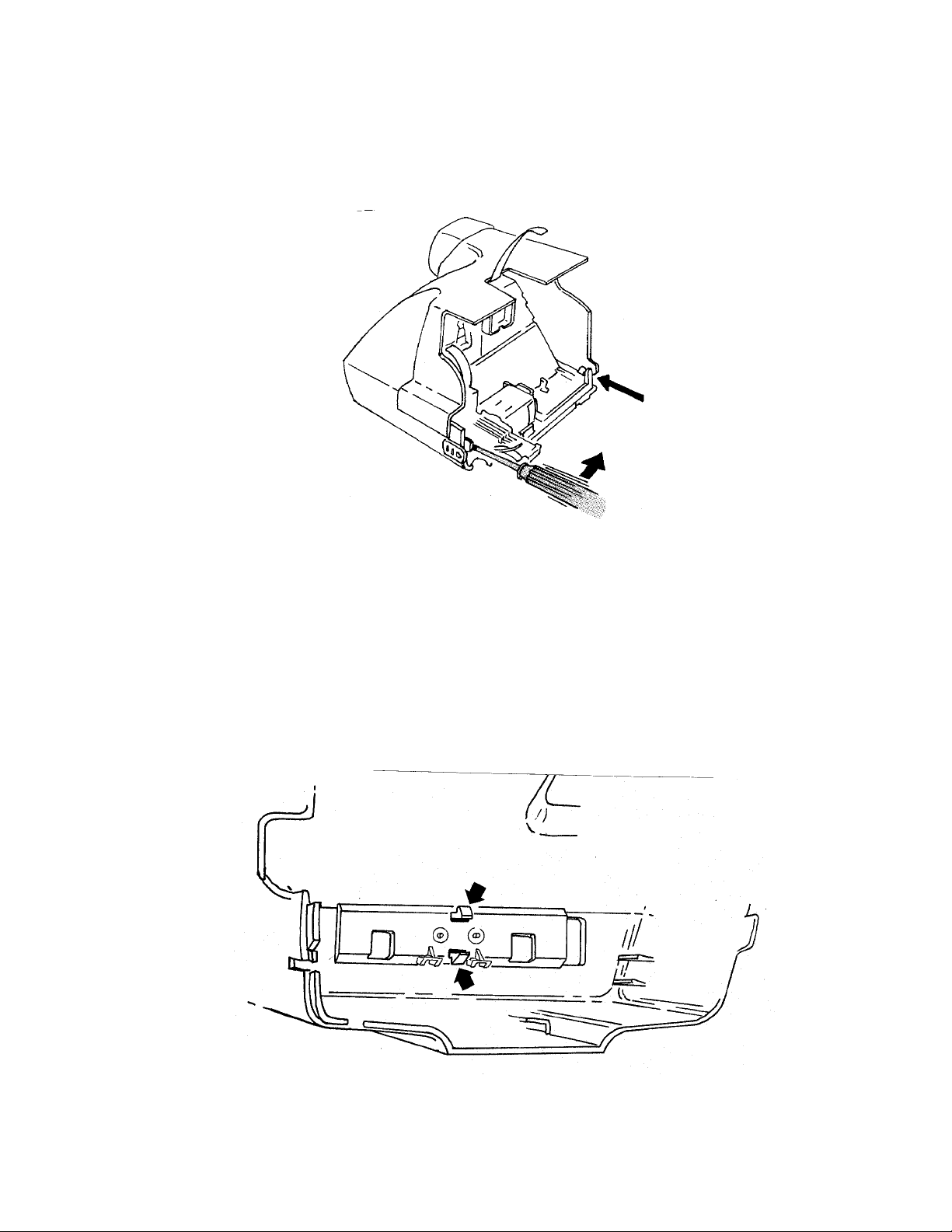
8. Open th e Film Do or to re mov e the A pro n . Ins er t a sold er ing aid, fir st at po sition A
and then B (Fig. 8), to free the Body detent lugs from the Apron. Carefully “lever”
the Apron out of the Body. Repeat the process on the opposite side. The S1
Bu tton and S1 0 Butt on with Return Spring will fall out.
Fig. 8 R e moving the Apro n fr om the C amera Body
9. Dis assemb le the A pro n using a sold er ing aid. First, r emove th e Panel containing t he
Close Up Lens and Trim Button Assemblies. Release the tabs at A and B (Fig. 9)
which hold the Panel to the Apron, then tilt out the top and lift it out, freeing lip
along the bottom edge.
(If it is necessary to remove the adhesive Lens Panel Decal from the Panel, gently
work a greenstick under a corner of the Decal and peel it off.)
Fig. 9 R e moving the Panel (Front Plate) fr om the Apron
43
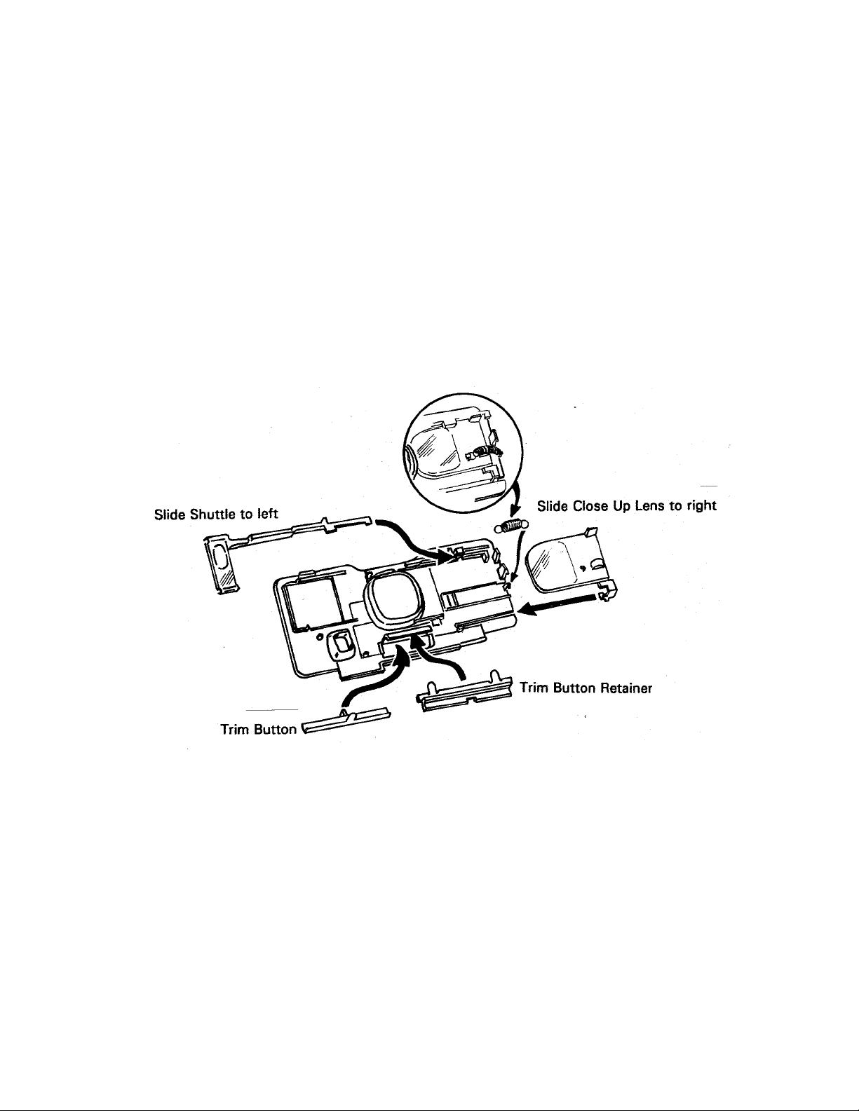
10. Disassemble the Close Up Lens, wearing finger cots o r lintless gloves. First, remove
the Spring with tweezers (Fig. 10).
Next, slide the Shutt le to th e left and lift its left en d to re move.
Now slide the Close Up Lens to the right and with a green-stick under the right end,
carefully lift the Lens until the to p edge clears the detent on the Panel.
Remove the Trim Button and Retainer by lifting each end of the Retainer away from
mo lded pin o n t he back of Panel (Fig. 1 0) .
Fig . 1 0 D isasse mbling Close Up Len s & Trim Button
44

Reassembling the Close Up Lens & Trim Button
11. Wearing finger cots o r lintless gloves to keep the Lens elements free of smudges,
first engage the “foot” at t he bot tom right corner of the Lens with the Panel (see
Fig . 1 1) . The n slide the Lens to the left s lightly a nd gen tly press down u nt il it
engages in its guides. The Lens should slide back and forth freely.
Fig. 11 Reassembling the Close Up Lens
12. Replace Shuttle by first sliding Lens to the left (Fig. 12). Do not r eplace Return
Spring yet. Now slip the right end of the Shuttle under the guide on the Panel. Slide
the Shuttle to the right into place. (The tab on the top of the Lens must be between
the tabs on the Shutt le.) Replace Lens Return Spring; check that Lens operates
smoothly.
Fig. 12 Replacing the Shuttle in the Close Up Lens
45

Body Disassembly
46
13. To r emove the Cone, insert a flat blade screwdriver at the locations shown in Fig. 13,
springing out the sides of the Body slightly. This frees the Cone from the catches
inside the Body. Lever the Cone forward, out of the Camera Body. The freed
Re lease Button will drop out .
Fig. 13 Removing the Cone from the Camera Body
14. Remove the piece parts from the Camera Body, beginning with the Strap Assembly.
From inside the Body, depress and release the tangs at the center of the Strap
Assembly (Fig. 14). From the outside, free the ends of the Strap Assembly from the
Body and remove it.
Fig. 14 Removing the Strap Assembly
47

15. Re mov e the Pa ck Sp ring by d epre ssin g it with your th umb and pu lling it for ward,
out of t he B ody (Fig. 15) . (If th e Camera has a T rip od Nut, it will now fall out.)
Fig. 15 Removing Pack Spring and if present, Tripod Nut
16. To Remove the Eyecup/Retainer (one unit), from inside the Body depress either pair
of the four tabs shown in Fig. 16 and remove the Eyecup/Retainer.
Eye Cup Retainer
Fig. 16 Removing the Eye Cup/Retainer
Body Reassembly
Replace parts removed in Steps 14 — 16. (Pack Sp ring holds Tripod Nut in place.)
48

Shutter Disassembly
49

17. Mount the Cone on a universal swivel fixture.
18. Remove Viewfinder Housing by tilting rear end upward (Fig. 17) and rotating it
forward (not e position of the tab at its left front).
Fig. 17 Removing Viewfinder Housing
19. With tweezers, remove Opening Blade Spring from rack and Base Block (Fig. 18),
first noting which notch on the rack it’s attached to and marking that notch to assure
correct reassembly later.
20. Remove Trim Slide by depressing the tang along its lower edge (Fig. 18).
Fig . 1 8 Removing Opening Blade Sp ring & Tr im Slid e
50

21. Remo ve Ambient Calibration Disk by de press ing tang a t bottom ( Fig. 19).
22. Re mov e I R Calibration Wedge, IR Lens Filte r a nd Ambient Lens ( Photopic) Filt er
from the Lens Mounting Plate (Fig. 19).
Fig. 19 Removing Ambient Calibration Disk, IR Calibration Wedge, IR Lens Filter &
Ambient Lens Filter
23. Remove Lens Mounting Plate by releasing the three tangs along the bottom edge,
which fastens it to the Shutter Base Block (see Fig. 20).
Fig. 20 Removing Lens Mounting Plate from Base Block
51

24. Remove Inertia and Walking Beam as an assembly, keeping Inertia Spring in place
(Fig. 21).
25. Wearing finger cot s or lintless gloves, remove Shutter Latch and Shutter Blades
(keep blades in the same relative positions and order in which they were removed).
See Fig. 21.
Fig. 21 Removing Inertia, Walking Beam, Shutter Latch and Shutter Blades
26. Disassemble Inertia and Walking Beam by removing Inertia Spring and lifting off
Inertia (Fig. 22). To aid in later reassembly, note the trapped position of each leg of
Spr ing before remo ving it.
Fig. 22 Disa ssembling In er tia from Walkin g Beam
52

27. Using Universal Flex Removal Tool, remove Flex from Contact Support Block and
Moto r (Fig . 2 3) . No w lift Wir e Bloc k As semb ly off the Cone an d r emove th e Flex
from the Wire Block (Fig. 23).
Fig. 23 Removing Flex from Contact Support Block, Motor and Wire Block
28. Remove the Base Block from the Cone by releasing the two locking tangs near
Motor and Counter Wheel (see Fig. 24), swinging bottom edge of Base Block out
and lifting it off the two shoulders at the top of the Cone.
Fig. 24 Removing Base Block from Cone
53

29. With Flex Removal Tool, disconnect Flex from the Solenoid connector (Fig. 25),
then lift Flex up and out from under the connector block. With point of soldering
aid, carefully free the Photocell (attached to the Flex) from its mounting on the Base
Block (see Fig. 25).
Fig. 25 Removing Flex from the Base Block
30. Us in g a solderin g aid, remo ve the Solenoid from t he B ase Bloc k by releas ing the
two tangs (see Fig. 26) Carefully pry out the Solenoid, with plunger in place, using
the soldering aid as a lever.
Fig. 26 Removing Solenoid & Plunger from Base Block
54
Shutter Reassembly
31. Replace the Solenoid with its Plunger in place into t he Base Block. The notch and
guide pin on the Plunger yoke must face the rear of the Base Block (see Fig. 27), so
that t he yoke pin rides freely in the Base Block slot.
Fig. 27 Replacing Solenoid with plunger in Base Block
32. Replace the Flex on the Base Block by first slipping the attached photocell up under
it s retain ing fin gers on th e Base Bloc k ( see Fig. 28 ). Now bo w the Flex sligh tly, slip
it under the Solenoid connector and down into position around the lens opening and
guide pin. Fold the Flex leg up and reconnect it to the Solenoid.
Fig. 28 Replacing the Flex on the Base Block
55

33. Remount the Base Block on the Cone by positioning the two openings at the top of
the Base Block over the corresponding projections on the Cone (see Fig. 29), then
rotating the Base Block down into position until the locking tangs near the Counter
Wheel and Motor snap shut.
Fig. 29 Remounting Base Block on Cone
34. Reconnect t he Flex to the Contact Support Block, Mot or and Wire Block Assembly
(see Fig. 30).
Fig. 30 Reconnecting Flex to Contact Support Block, Motor and Wire Block Assembly
56

35. Reassemble the Shutter blades by inserting a dowel pin 3/32″ x 3/4″ (2.4 x 19 mm)
in the ho le in the Base Block shown in Fig. 31. Wear ing finge r c ots or lintless
gloves, install the bottom, middle and top Shutt er Blades over the 3/32″ dowel pin,
and with the molded pin on Base Block projecting up through the slot in Blades
(Fig. 31).
Fig. 31 Replacing the Shutter Blades
36. Mate the Inertia and Walking Beam together and install the Inertia Spring as shown
in Fig. 32. Check that both parts pivot smoothly and are returned by spring action.
Fig . 3 2 Reassembling I n er tia, W alking Beam & S pr ing
57

37. Replace the Inertia and Walking Beam Assembly by engaging the four pins in the
Blades, Solenoid Plunger Yoke and Base Block pivot point (see Fig. 33). Carefully
remove the dowel pin and test Shutter Blade operation by moving the Walking
Beam Assembly to produce an aperture.
Fig . 3 3 Replacing Walk in g Beam/Inertia Ass embly
38. Pivot the Inertia slightly to the right and slip the Shutter Latch down onto the pivot
beneath the Inertia (Fig. 34). It must mate with the S5 Actuato r .
Fig. 34 Replacing the Shutter Latch
58

39. Replace the Lens Mounting Plate by placing the two tabs at the t op into their
correspo nding openings in the Base Block (Fig. 35). Tilt the Plate down- ward into
position, making sure the Inertia pivot post enters its hole in the Base Block. Snap
the three locking tangs closed at the bottom of the Plate.
Fig. 35 Replacing the Lens Mounting Plate
40. Replace the Trim Slide in the Lens Mounting Plate by depressing the tang below it
and sliding it into place (see Fig. 36).
Fig. 36 Replacing Trim Slide
59

41. Replace the photometrics in this order, as shown in Fig. 37: Ambient Lens Filter
(green), Infrared Lens Filter, IR Calibration Wedge over the pivot on the IR Filter
Lens, and the Ambient Calibration Disk with the stops on the bottom.
Fig. 37 Replacing photometrics on Lens Mounting Plate
42. Replace Opening Blade Spring with one end at the original (marked) rack position,
the other end on t he Walking Beam pin (Fig. 38). Test that the Shutter latches and
unlatches properly.
Fig. 38 Replacing Opening Blade Spring
60

Drive Disassembly
61

43. If n ecessary, re move the S1 Leaf Spr ing from t h e Gear D rive Cover by pulling it
forward slightly and then lifting it up (see Fig. 39).
44. Disconnect the red jumper wire from the S10 movable contact by depressing the
spring finger to release it (Fig. 39). Move the wire out of the way.
45. If necessary, remove the S10 movable contact.
46. Disconnect the bare (+) battery contact wire from the Contact Support Block and
the S10 fixed contact by depressing the contact spring fingers. Free the wire from
the Drive Cover and move it away.
47. If necessary to remove the S10 fixed contact, release the tangs holding the contact
by inserting the pins on Tool 12536 into the two holes shown in Fig. 39. The
contact can t hen be pushed out with a screwdriver.
Batter y contact
jumper wire to
wire block
To + battery
contact
S1 Leaf spring
S10 Moveable contact
To cont act
support
block
S10 Fixed contact
Gear drive coverBare Wire
Fig. 39 Disconnecting wires and removing parts from the Gear Drive Cover
62

48. Release the tension on the Counter and Pawl Springs (see insets A and B, Fig. 40).
49. Release the Drive Cover forward detent (inset C), the hanger detent (inset D) and
the rear detent ( inset E).
NOTE: In step 49, the metal gear (#5) may become dislodged. Be careful that it is not lost.
Fig. 40 Releasing springs and Gear Drive Cover detents
63

50. Refer to Fig. 41: place your thumb over the left end of the Gear Drive. Slowly and
carefully lift the right end of the Cover. Remove the Cover by walking the left end
free of its detent. Use car e to not break t he det ent .
Fig. 41 Removing the Gear Drive Cover
51. Re move the Timing Gear, Pa ck Pawl, Pawl Spring, Doo r Pawl and, if not dislod ged
earlier, Gear 5.
Fig. 42 Parts removal from Gear Drive
64

52. Re move the Counter and Count er Sp ring by pulling t he C ounter off its s haft (Fig . 4 3) .
Remove the four remaining Gears and the Spacer from their shafts (Fig. 43).
Release the back end of the Pick Return Spring and slide the Pick forward. Lift both
parts fre e of t he C on e As semb ly (Fig. 43)
Fig. 43 Removing the Counter, Gears & Pick
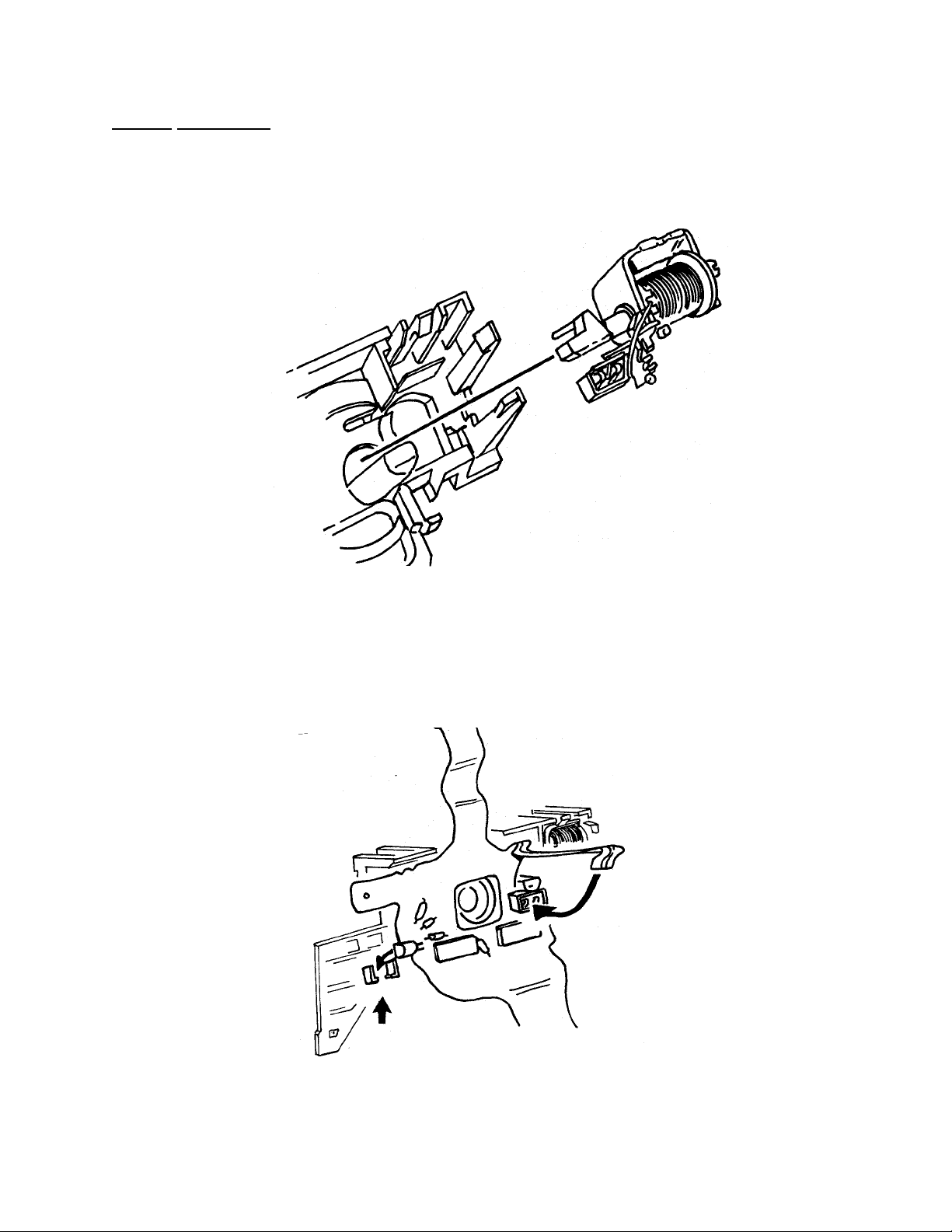
53. Push the Slider in as shown in Fig. 44 inset. Push in detent and the Contact Suppor t
Block will pop out . Let it han g from th e Flex, if Flex has not already been re moved.
Pull t he S1 Slider and S5 Ac tuator fre e of t he C on e ( Fig. 44) . D isasse mble Slider
components.
Fig. 44 Removing S1 Slider and S5 Actuator
65

Drive Reassembly
54. In stall the S5 Act ua tor o n t he Slider. Ho ld the m together while installing th em on
the Cone.
55. In stall the Slide r Asse mbly o v er th e p iv ot on the hou sing (F ig. 45). B e sur e the tip
of the S5 Actuator is over the Shutter Latch (see Fig. 45).
Fig. 45 Replacing Actuator and Slider Assembly
56. Push the Slider back and position the Contact Support Block onto the housing (see
Fig. 46). Before snapping detents closed, be sure that the lower S1 cont act is
positioned between the Slider fingers. Snap detents closed and release Slider.
Verify that Slider moves freely and Slider fingers and switch contacts are pr operly
positioned.
Fig . 4 6 V er ifyin g S lide r-Switch contact relationship
66

57. Using Fig. 47 as a guide, replace the four plastic gears, metal gear #5 and the
spacer.
Fig. 47 Gear placement guide
58. Referring to Fig. 48, replace the Door Pawl and Pawl Spring.
Fig. 48 Replacing Door Pawl and Spring
67

59. Set the Counter Spring into the Counter (Fig. 49), wind the Spring, push in the
Slider and place the Counter on its shaft. Temporarily hook t he Spring onto the
lower detent. (No te that t he number 6 is upside down and facing forward.)
Release the Slider: the Counter should lock into place and the number 7 drop so it is
facing forward (upside down).
Fig. 49 Replacing the Counter
60. Install the Pack Pawl in the position shown in Fig. 48.
61. Install the Pick, with Return Spring attached, as shown in Fig. 50. Attach Spring to
housing and be sure Pick slides freely.
Fig. 50 Replacing Pick and Return Spring
68

62. In stall the T imin g G ear on its shaft (Fig. 51). It may be installed in a ny pos ition as
long as none of its cams interfere with the motion of the Pick. (The camera will
t ime itse lf in it s first cyc le. )
Fig . 5 1 Replacing the T iming Gear
63. Replace the Gear Drive Cover (see Fig. 41), carefully maneuvering it into place to
prevent breaking the rear (left end) detent. Snap-in the forward detent first, then the
hanger detent, finally the rea r detent.
64. Using a dental pick, set the Counter Spring and Pawl Spring as shown in Fig. 52.
Fig. 52 Setting Counter and Pawl Springs
69
65. Replace any Contacts and parts removed from the Gear Drive Cover in steps 43 —
To + Battery
Contact
47. Reconnect the (+) batt er y wire to the S10 fixed contact and the Contact
Support Block, and the red jumper wire to the S10 movable contact (see Fig. 53).
To wire
block
S1 Leaf
Spring
S10 Moveable
Contact
To cont act
support block
Bare wire
S10 Fixed
Contact
Fig. 53 Reconnecting wiring to contacts
70

Door and Spread System Disassembly
66. Remove the Door Assembly by disengaging the hinge on the right side (opposite
gears), t hen the hinge on the left side.
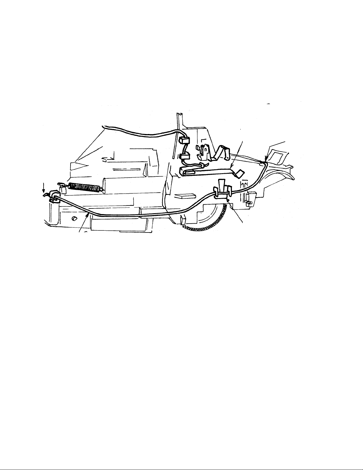
67. Remove the Spread System Assembly by inserting an Exacto knife with a #11 blade
just below the lower leg of the spring, on the left (non-gear) side (see Fig. 54).
Keep the blade flat, in the same plane as the rollers, with the dull edge against the
end plate. The tip of the blade should be halfway between the front and rear legs of
the spring.
68. Swing the knife handle to the right a little so the tip of the blade pushes to the left,
against t he inside of the end plate (Fig. 54 ). Th is will unloc k the hidden detent in
the left end plate from its channel in the door, allowing the left end of the Spread
Sys tem to be pulled out slight ly. Use care: detent will break off if deflected too
far.
69. Repeat the process on the right (gear) side, gently pushing the tip of the blade to the
right slightly, releasing the detent in the right end plate from the door channel. Now
remove the Spread System Assembly.
Fig. 54 Removing the Spread System from the Door
71

To complete the reassembly of the Camera:
67. Replace the Viewfinder on the Cone
68. Replace the Cone into the Body
69. Replace the S1 and S10 Butto ns
70. Replace the Release Button
71. Replace the Apron to retain the Release Butto n
72

[This p age intentio nally blank]
73

[This p age intentio nally blank]
74

SECTION 5 — MODEL 636 CAMERA TROUBLESHOOTING
Introduction
Before performing the troubleshooting procedures presented in this section, you should be
t h oroughly fa miliar with the Theo ry/ Se quence po rtion of this
manual. Quite obviously you must know how the 636 Camera works before you can start to
diagnose its pr ob lems.
Initial Inspect io n
The following procedure should be done before you get involved in an operational check of
the 636 Camera. Before long, you will find this procedure becomes automatic an d you will
no lo ng er have to refer to it for s tep-by-step guidance.
1. Visual
a. Inspect the camera for obvious faults such as gaps between body parts; and missing,
broken, distorted, scratched or otherwise defective parts. Pay particular attention to
lens, viewfinder and flash shield components for signs of smudges and foreign
matter. Examine the camera for cosmetic defects which are beyond allowable
standards.
b. Look into the lens. The shutter blades should be closed.
c. Look at t he C ounter window. W ith no film in th e Camera th e window shou ld be
blank, indicating that the Counter has reset.
2. Pre-Operat ional
a. With the strobe clo s ed, p ress the S 10 button. It s hould not move, be ing he ld out by
the interlock tab on the strobe housing.
b. Erect and then close the stro be. I t should move through its entire travel freely with
no binding. Also, when the strobe is erected and the camera is tilted forward, t he
str obe sh ould not fa ll forward.
c. Move the lighten/darken control tab from full-light to full-dark and then back to its
nomina l detent posit ion . It shou ld move fre ely with n o b inding d ur ing its travel.
d. Press the front door release butt on. It sho uld offer some resistance to t humb
pressure. At t he forward end of its travel, the release button should drop the front
door open. Close the front door to be certain it latches properly.
75

e. Press the S10/S1 buttons through t heir entire travel. They should move smoot hly
with no binding.
f. With t h e fr ont do or open, look int o the film comp artment. Check th e following:
— Pack spring and battery contacts are not distor ted.
— Taking mirror is not broken, loose or scratched.
— Spread ro ll bracket assembly components are OK and rollers move freely.
— Spread ro llers are clean.
— With pick height gauge #12430 or #12504 (see P.A. SX-70 #291) see that the pick
is positioned correct ly.
— No foreign mat er ial in film c avity.
— Hanger is in proper position.
— Pack pawl leg is in a down position and not distort ed.
— Co ne fille r #550851A is in position or cone has molded fix (See RIB 600AM #6).
3. Functional Test
Perform the following functional test o n the 636 camera using film pack simulat or #12467
(.3 ohms) and power supply Power Mate #12531 or Lambda #12429.
1. Setup
a. Plug the film p ack simulator into t he po we r supply. Be sure the polarity is correct.
b. Plug the power supply into a 110 VAC source.
c. Turn the power supply switch ON.
d. Adjust the out put voltage to 6.0 volts.
76

2. Test
a. Open th e fron t do or of the camera and install the film pack simulator . The camera
should not cycle.
b. Remo v e the film pack simulato r a nd install doo r p awl closure #12082.
c. In stall the film pack simulator again :
— The camera should go through the dark slide cycle.
— The shutter blades should remain closed.
— The stro be should not charge (g r een LED o ff)
— The counter should go from blank to #10.
d. Depress the S10 Button lightly so that it just touches the S1 Button.
— Four to six seconds later, the green LED should light, indicating strobe is charged.
LED stays on about 30 seco nds.
— Depress S10/ S 1 Bu tto ns fully: the stro be should fire.
— Repeat step d. four more times.
e. Cover the photocell with black photo gr aphic tape and turn the Camera to face you.
— Depress the S1 But ton only: the blades should open to a small aperture (f/20) and
then close.
— Repeat t he st ep abo ve four t imes.
— Remove the tape from the photocell.
f. Depress the Sl0/S1 buttons fully:
— the camera will not cycle (Empty Pack L ockout).
— the strobe will ch ar ge .
— the gre en L ED will light in 4 — 6 seconds.
— the stro be will not fire.
— the counter window will b e blank .
77

g. Re mov e the film pack simulato r a nd do or p awl closure:
— the counter will return to its s tartin g p osit ion.
h. In sert a known good film pack wit h film into th e camera. Take a 2-foo t cyan
background picture with strobe:
— observe th at t he film transport and d elive ry systems ar e fun ctio ning pr operly.
— observe the finished picture for complete coverage.
— observe the finished picture for evidence of dirt or cracks on the taking mirror.
78

TROUBLESHOOTING CHARTS
(NOTE: Also see the RIB and Product Alert listing following these charts)
PROBLEM PROBABLE CAUSE CORRECTIVE ACTION
Dark Slide Cycle 1.Door pawl spring defec- 1. Replace spring
with Front Door Open tive or not loaded or load spring
(Non-Continuous) (If under pa ck pawl. properly.
cycling continuously
go to Continuous 2.S1 slider fingers and 2. Disassemble and
Cycling chart) switches on contact install properly
support block not
interfaced properly.
3. S1 switch contacts 3. Re-form S1 contacts
deformed. (Closed with if possible. Replace
front door open — check contact support
with meter). block if necessary.
4.Conta ct support block 4. Replace contact
defective. support block.
No Dark Slide Cycle 1. S9 switch open (check 1. Re-form S-9 switch
with meter). contacts. Replace
support block if
necessary.
2. S1 slid er fingers and 2. Disassemble and
switches on contact install properly.
support block not
interfaced properly.
3. S1 slider cam not mated 3. Disassemble and
to counter properly. install properly.
4. S1 switch contacts 4. Re-form S1 contacts
deformed (closed with if possible. Replace
front door open — check contact support
with meter). block if necessary.
5. Contact support block 5. Replace contact
defective. support block.
6. Battery (+) wire not 6. Install battery wire
trapped in contact properly.
support block properly.
7. Flex circuit motor 7. Install flex motor
contacts not seated contacts properly.
properly.
8. Counter spring defective 8. Repair or replace
or not loaded properly. sprin g.
79

PROBLEM PROBABLE CAUSE CORRECTIVE ACTION
No Dark Slide Cycle 9. Battery contact height 9. Replace battery
(cont’d) mar gin al or not seated contacts.
properly.
10.Fl ex circu it defecti ve. 10.Repl ace flex circuit
No S1 response 1. Defective S-1 button 1. Replace S1 button
or S-l slider. or S1 slider.
2. S1 slider and contact 2. Disassemble and
support block not install properly.
interfaced properly.
3. S1 switch contacts de- 3. Re-form S-1 contacts
formed (d o not close). or repla ce contact
support block if
necessary.
4. Poor connect ion between 4. Check connection and
flex circuit and solenoid. correct problem.
5. S9 is closed (check with 5.Re-form S-9 contacts
meter). NOTE: In this or replace contact
failure, camera will cycle support block, if
but blades remain closed. necessary.
6. Solenoid defective 6. Replace solenoid.
(should read 2 to 3 ohms).
Continuous Cycle 1. Pack pawl override 1. See RIB #600AM 6.
(Camera ejects
film continuously) 2. Solenoid gap incorrect. 2. Adjust solenoid gap.
3. Shutter blades binding: 3. Repair or replace
blades as necessary.
a. Foreign matter on
blades.
b. Blades distort e d.
c. Blades not attached
to walking beam.
4. Blade guide pin in 4. Replace shutter
shutte r bas e block broken baseblock.
5. Shutter latch binding. 5. Correct cause of
binding.
6. Solenoid plunger sticky. 6.Repair/replace
solenoid.
80

PROBLEM PROBABLE CAUSE CORRECTIVE ACTION
Continuous Cycle 7. Counter spring unwound 7. Install counter
(cont’d.) or not trapped in spring correctly
counter properly
8. S-1 slider cam interface 8. Install S1 slider
with counter not correct cam properly.
9. S5 P&L contacts under 9. Disassemble and
S5 actuator. install properly.
10.Shutter assembly not 10.Disassemble and install
seated in cone properly. properly making certain
interface with drive
is OK.
11. Flex circuit defective. 11.Replace flex.
Continuous Cycle 1. Stripped teeth on timing 1. Replace timing gear.
(Camera runs but gear.
does not eject
film) 2. 5th gear missing or not 2. Repair or replace.
in position.
Mid-Cycle 1. Solenoid gap incorrect. 1. Adjust solenoid gap.
Failure
2. Battery (+) wire not 2. Examine battery wire.
properly seated in con tact support block or in
solderless battery contact.
3. Blades binding. 3. Examine blades & repair
or replace as necessary
4. Battery contact height 4. Replace battery
marginal or not seated contacts.
properly.
5. Contact support block 5. Replace contact support
defective. block.
6. Solenoid defective. 6. Replace solenoid.
7. Flex circuit defective. 7. Replace fl ex circui t.
81

PROBLEM PROBABLE CAUSE CORRECTIVE ACTION
High Current Drain NOTE: First determine whether problem is with strobe or camera.
Replace strobe with known good test strobe. If operation is
OK with test strobe, problem is in original strobe which must be
replaced. If operation reveals high current drain with good test
strobe, problem is in camera. Continue below:
1. Switch contacts on block 1. Re-form contacts or
are distorted. r eplace contact support
block as n e ce s sar y.
2. Contact support block 2. Replace contact support
defective. block.
3. Flex circuit defective. 3. Replace fl ex circui t.
Strobe Failures: NOTE: First determine whether the problem is with the
No Flash strobe or the camera. Replace the strobe with a
No Charge known good test strobe. If operation is OK with
LED stays on test strobe, the problem is with the original
strobe which must be replaced. If operation
reveals probl e ms with g ood test strobe, problem
is in camera. Continue below:
1. SlO button a nd movable 1. Assemble camera
SlO contact interface properly.
incorrect.
2. SlO contact distorted. 2. Re-form contact.
3. SlO jumper wire not 3. Install jumper wire
trapped in movable properly.
contact or wire block
properly.
4. Bare (+) wire not 4. Install (+) wire
trapped in fixed SlO properly.
contact properly.
5. Flex circuit not 5. Install flex properly.
installed into PC board
properly.
NOTE: Use meter to check continuity
between points.
82

PROBLEM PROBABLE CAUSE CORRECTIVE ACTION
LED does not light NOTE: If strobe does not function,
see Strobe Failures.
1. LED shor t ed a t PC boar d. 1. Correct short.
2. LED not installed 2. Install LED properly.
pr op e rly on PC boa rd.
3. LED defective. 3. Replace LED/PC board.
4. Flex circuit defective. 4. Replace fl ex .
5. S trobe PC board 5. Repla ce s trobe .
defective.
6. Film battery dead/film 6. Insert fresh film pack.
pack absent.
Light leaks in 1. Light seal on cone 1. Install cone light
picture missing. seal.
2. Baseblock photographic 2. Install photographic
tape light seal missing. tape on baseblock.
3. Mirror cover light seal 3. Install mirror cover
not positioned properly. light seal properly.
4. Film pack spring 4. Replace pack spring.
defective.
Close-Up Lens Does 1. Lens return spring 1. Install spring
Not Function missing or out of properly.
Properly position.
2. Shuttle binding in 2. Install shuttle
apron guide rails. properly.
3. Close-up lens not 3. Install lens
riding in apron properly.
rails properly.
4. Return spring tab 4. Replace lens panel.
broken.
83

Additional 600-line Camera Troubleshooting help from Product Alerts and RIBs
NOTE: Ma ny of th e problems a nd fix es described below were temporary solut ion s, later
permanently correct ed by design/manufacturing changes. Thus the repair material
desc ribed below may or may not be pres ent in or applicable to a later versio n o f the
camera.
Subject Bulletin # Date
Troubleshooting Update — 600 line cameras 600AM #46 3/36/84
Ex posure Flex P ho tocell movemen t
Trapped Shuttle in CU lens 600AM #92-35 10/27/92
Continuo us cycle from an gled film pack
Strobe LEDs: red only; red & green; green only 600AM #83 10/31/87
Hybrid 2-LED Strobe PC Boards 600AM #92-22 3/26/92
Low-cost, one green LED Strobe 600AM #91-17 12/16/91
No stro be charge from dirty S10 contacts 600AM #48 5/2/84
Black/dark pictures from light leaks to photodiode 600AM #93-40 1/18/93
Black pictures from light leak behind strobe 600AM #95-45 7/9/95
Streaked pictures from apron light leaks 600AM #78 8/13/87
Continuous cycling from Contact Support Block 600AM #91-16 12/16/91
Release Butto n-Do or Latch clearance problem 600AM #91-6 5/28/91
Oxidation on flex circuit solder pads 600AM #96 12/11/89
84

SECTION 6 — 636 CAMERA TESTING WITH THE STAR TESTER
CONTENTS
Page
A. Test Specifications for Model 636 Camera 86
B. Graywall Preparation 86
C. Setting Up the Model 12650-2 Star Tester 88
D. Star T ester Contr ols and Indicators 92
E. Testing the Model 636 Camera: 95
1. Pretest pr ocedures 95
2. Order of Model 636 tests 95
3. Model 636 Test procedures:
a. Flash Timing 96
b. Ambient Exposur e 97
c. Strobe Exposure (Graywall) 98
d. ZLS Output 99
F. Camera adjustments (correcting out-of-spec test results):
1. Flash Timing 100
2. Ambient Exposure 101
3. Strobe Exposure 102
G. Calibrating the Model 12650-2 Star Tester 105
85

A. Test Specifications for Model 636 Camera
Test: Specification:
Flash Timing 2.0 to 1 3.0 ms
Ambient Exposure -0.30 to +0.10
Strobe Exposure (Graywall) 0.0 to -0.50
ZLS Output 260 to 400 ZLS
Charge Time (2nd cycle) 4 sec. max
Energy Draw (2nd cycle) 12.5 amp sec.
B. Graywall Preparation
1. The target sho uld be constructed of a flat hard board material such as Masonite. It must be
a minimum size of 4 ft . x 4 ft. (1 .2 m x 1.2 m).
2. Prepare the surface by applying a primer coat of flat white latex paint. The surface must
have a uniform white appearance when dry. If necessary, use two coats of flat white latex
paint to achieve uniform coverage. Allow 24 hours for the primer to dry.
3. After the primer has dried, apply two coats of special gray paint which has been provided.
The two co ats must be applied in opposite directions. For example, apply the first coat in
an up and down direction and the second coat in a left and right direction. Allow plenty of
drying time between the two co ats. The amount of drying time is dependent on temperat ur e a n d humidity.
4. Choose a suitable location for th e test in g are a. The follo wing cond itions must be me t:
a. The testing area must be located where lighting on the graywall target will
remain b elow 10 can dle s/square foot. Most ro om lighting meet s this
requirement. Avoid areas where outside light shining through a window can
strike the target resulting in erroneous strobe exposure readings.
b. Select an area where the graywall target can be secured to a wall which is
perfectly flat. The area must be large enough to allow the testing equipment to
be placed 4.5 feet (137cm) from the target (see Figure 1). The area must be
free of any obstacles between the camera under test and the graywall.
86

5. Secure the graywall target to the wall and set up the t est equipment as instructed in the
setup procedur es. T he center o f the tar get must be aligned with the taking lens of the
camera under test.
4 ft
(1.2 m)
4 ft
4 ft
(135 cm)
(1.2 m)
Fig. 1 Graywall setup
87

C. Setting up the Model 12650-2 Star Tester
1. Install the Star Tester o n a level surface with sufficient clearance to allow prop er air flow
for the coo ling fan and exhaust vents. Also, the test er work surface should be located so
the various fixtures can be located 4.5 feet (137 cm) from a graywall target.
2. Insert a modified strobe fixture #12657B (see inset, Fig. 2) into two o penings on the tester
(Fig. 2). (For details of this modified fixture, see Product Alert 600AM #92-30, dated 7/
31/92.) Be certain the fixture is fully seated.
Push adaptor
firmly in to tw o
openings
Strobe
Adap t or
#12651
Modified
St robe Fixture
#12657B
Fig. 2 In stalling modified Strobe Fixture 12657B
88

3. E r ect the electronic flash of the Model 636 and place the camera on the Star Horn
#12625.
4. S et the horn with the mounted camera against the test er . Using the leveling legs, raise
or lower the t ester so t hat the electronic flash is aligned with and fits into the adapter
window (Figure 3).
Flash mu st fit int o
stro be adapt or
Us e levelers to
raise o r lower
tester
Fig. 3 Aligning Camera on Horn with Tester window
89

5. Remo ve the horn with mounted camera from t he proximity of the t ester. Car efully, tilt
the tester and install two risers #12885 under the leveling legs. Tilt the ot her side of the
t ester and insta ll two mo re riser s un de r the t wo remaining leveling legs ( Figure 4).
Risers #12885
Fig . 4 Installing Risers under T ester’s leveling legs
90

6. Place horn riser #12884 under the star tester horn (see Fig. 5).
7. Set the horn in the lowered position (Fig. 5).
Horn riser
#12884
Fig. 5 Test setup and Horn Riser position for Model 636
Horn in low er ed
position
91

D. Star Tester Controls and Indicators
The Star Tester #12650-2 is used to check exposure and timing related parameters of Polaroid
cameras. This section deals exclusively with the 636 Polaroid Camera. The light box and the
ele ctr onics re quire d to comp ute and display exposure, t iming and funct ional test measure ments
are housed in a single chassis (see Fig. 6).
Presented below are the functions of the controls and indicators o n t he St ar T ester. Refer to
Figure 6.
KEY CONTROL/INDICATOR FUNCTION
1 Dis c P osit ion Lamps Not used
2 Reset Butto n Clears Tester electronics
between tests.
3 Dis c/Ride T ime Switch No t used for 636
4 Test Selector Switch Selects test mode (8 for 600
cameras, 3 for other cameras)
5 Horn Volts Selector Allows selecting supply
Switch voltage of 5V (low), 6V (nom),
6.8V ( high ). Simulates film
pack battery.
6 20 Volt/2000 Volt Used in conjunction with volt
Selector pro be jack (key 7) and DC volt
mete r (key 9); allo ws Te ster
to be used as voltmeter.
7 Volt Probe Jack Accepts standard probe for
checking DC voltages in
cameras under test.
8 Timin g Meter Provid es digital readout of
stro be recycle time and flash
timing.
9 DC Volts Meter Provides digital readout of
circuit voltages. May also be
used with probe in Volt Probe
jack (key 7).
10 Stops Err or Meter Pro vides digital readout of
ambient & strobe exposure.
11 DC Current Meter Provides digital readout o f
input energy (amp/secs) during
flash charge in ZLS mode. May
also be used to monitor
dra in in other test mod es.
92

KEY CONTROL/INDICATOR FUNCTION
12 ZLS Meter Provides digital readout of flash output.
13 Power S witch ON/OFF switch for T este r line
voltage. Illuminates when ON.
Contains circuit breaker.
14 Pack Simulator Jack Provides a connection for Pack
Simulator, allowin g T ester to
be used as a power supply.
15 Strobe Adapter Aligns electronic flash of camera under test to
Tester. No . 12657B used for 636 Camera
16 Horn Connector P r ovides the electronic inter- face for the Star
Tester Horn.
17 Disc Detector Not used with 636.
Connector
18 J4 Connector For futur e applications.
19 Test Po int Used for electronic interface
Connections with oscilloscope and a lso used for
Tester calibration.
CAUTION: When the Star Tester is not being used for a length of time, turn the Test Selector
knob to 660 FLASH EXP. This prevents unnecessary wear of the light source
bulb and k eeps th e T ester in a neutral st ate, ready for t he immediat e r esumption of
testing.
93

Fig. 6 Star Tester Controls and Indicators
94
Loading…