
ГазоАналит
Газоанализаторы Drager X-am 2500 многокомпонентные взрывозащищённые портативные. Краткое описание и технические характеристики.
Скачать
Pdf 3.58 Mb
Язык: RU
Dräger X-AM 2500 Measuring Instruments PDF User Guides and Manuals for Free Download: Found (7) Manuals for Dräger X-AM 2500 Device Model (User Manual Manual, Technical Manual)
The Dräger X-AM 2500 is a highly efficient and versatile gas detection device that excels in ensuring safety in various industrial environments. It is designed for use in the monitoring of hazardous gases, providing reliable protection for workers in sectors such as oil and gas, wastewater treatment, and confined space entry. With its advanced features and user-friendly design, the X-AM 2500 stands out as a crucial tool in gas detection technology.
One of the prominent features of the Dräger X-AM 2500 is its ability to detect multiple gases simultaneously. This four-gas detector can monitor flammable gases, oxygen levels, and toxic gases, making it suitable for a wide range of applications. The integration of the latest sensor technology allows for quick and accurate readings, ensuring that possible dangers are recognized and communicated effectively.
Another significant aspect of the X-AM 2500 is its durable and robust design. This device is built to withstand harsh working conditions, featuring a sturdy casing that is both lightweight and impact-resistant. The instrument is also rated IP67 for water and dust resistance, ensuring reliable performance even in challenging environments. This durability gives users confidence that the Dräger X-AM 2500 will perform when it is needed most.
In terms of usability, the X-AM 2500 is designed with the user in mind. Its intuitive interface and clear display make it easy to operate. The buttons are strategically positioned for quick access, allowing users to navigate through settings seamlessly. The device also includes features such as an audible and visual alarm system, giving users immediate alerts when dangerous gas levels are detected. This ensures maximum safety and awareness during operations.
The battery life of the Dräger X-AM 2500 is another attribute worth mentioning. Equipped with a rechargeable battery, the device can last for an extended duration, reducing the need for frequent recharging. This is especially beneficial in environments where constant monitoring is essential. Users can count on the X-AM 2500 to provide consistent performance throughout their shifts.
Key Features of the Dräger X-AM 2500:
- Simultaneous detection of up to four gases.
- Durable and robust design for harsh conditions.
- Intuitive user interface and clear display.
- Audible and visual alarms for immediate hazard alerts.
- Long battery life with rechargeable options.
Moreover, Dräger provides excellent customer support and service for the X-AM 2500. Users can benefit from easy access to technical support, servicing, and maintenance. This commitment to quality service ensures that users have a reliable partner in safety monitoring throughout their usage of the device.
In conclusion, the Dräger X-AM 2500 is an exceptional gas detection device that combines advanced technology with user-friendly features. Its ability to monitor multiple gases with precision, coupled with its robust design and long-lasting battery life, makes it an indispensable tool for safeguarding workers in potentially hazardous environments. Whether you are in the construction industry, working with chemicals, or in any field that requires air quality monitoring, the X-AM 2500 is certainly a worthwhile investment. Safety is paramount, and with Dräger’s expertise, the X-AM 2500 provides a significant layer of protection to ensure that workers return home safely each day.
Dräger X-am 2500
(MQG 0011)
Technical Manual


Content
Content
1 For your safety . . . . . . . . . . . . . . . . . . . . . . . . . . . .4
1.1 General safety statements . . . . . . . . . . . . . . . . . . . .4
1.2 Definitions of alert icons . . . . . . . . . . . . . . . . . . . . . .4
2 Description . . . . . . . . . . . . . . . . . . . . . . . . . . . . . . .4
2.1 Product overview . . . . . . . . . . . . . . . . . . . . . . . . . . .4
2.1.1 Front . . . . . . . . . . . . . . . . . . . . . . . . . . . . . . . . . . . . .4
2.1.2 Rear side . . . . . . . . . . . . . . . . . . . . . . . . . . . . . . . . . .4
2.1.3 Display . . . . . . . . . . . . . . . . . . . . . . . . . . . . . . . . . . .4
2.1.4 Special symbols . . . . . . . . . . . . . . . . . . . . . . . . . . . .4
2.2 Intended use . . . . . . . . . . . . . . . . . . . . . . . . . . . . . . .5
2.3 Approvals . . . . . . . . . . . . . . . . . . . . . . . . . . . . . . . . .5
2.3.1 Safety Instructions . . . . . . . . . . . . . . . . . . . . . . . . . .5
3 Operation . . . . . . . . . . . . . . . . . . . . . . . . . . . . . . . . .6
3.1 Preparations for operation . . . . . . . . . . . . . . . . . . . .6
3.1.1 Charging the batteries . . . . . . . . . . . . . . . . . . . . . . . .6
3.1.2 Replacing the batteries / rechargeable batteries . . .7
3.1.3 Switching on the instrument . . . . . . . . . . . . . . . . . . .8
3.1.4 Switching off the instrument . . . . . . . . . . . . . . . . . . .8
3.2 Before entering the workplace . . . . . . . . . . . . . . . . .8
3.3 Configuration . . . . . . . . . . . . . . . . . . . . . . . . . . . . . . .9
3.3.1 Standard gas configuration . . . . . . . . . . . . . . . . . . . .9
3.3.2 Standard instrument configuration . . . . . . . . . . . . .10
3.3.3 Configuring the device . . . . . . . . . . . . . . . . . . . . . .10
3.3.4 Export data memory and display graphically . . . . .11
3.4 Running the bump test . . . . . . . . . . . . . . . . . . . . . .11
3.4.1 Manual implementation without documentation
of the results in the instrument memory . . . . . . . . .11
3.4.2 Menu implementation with the documentation of
results in the instrument memory . . . . . . . . . . . . . .12
3.4.3 Automatic implementation with the
Bump Test Station . . . . . . . . . . . . . . . . . . . . . . . . .13
3.5 During operation . . . . . . . . . . . . . . . . . . . . . . . . . . .13
3.6 Identifying alarms . . . . . . . . . . . . . . . . . . . . . . . . . .14
3.6.1 Concentration pre-alarm A1 . . . . . . . . . . . . . . . . . .14
3.6.2 Concentration main alarm A2 . . . . . . . . . . . . . . . . .14
3.6.3 STEL/TWA exposure alarm . . . . . . . . . . . . . . . . . .14
3.6.4 Battery pre-alarm . . . . . . . . . . . . . . . . . . . . . . . . . .14
3.6.5 Battery main alarm . . . . . . . . . . . . . . . . . . . . . . . . .14
3.6.6 Instrument alarm . . . . . . . . . . . . . . . . . . . . . . . . . . .14
4 Menu functions . . . . . . . . . . . . . . . . . . . . . . . . . . .15
4.1 Activating the Info mode . . . . . . . . . . . . . . . . . . . . .15
4.2 Opening Info-Off Mode . . . . . . . . . . . . . . . . . . . . . .15
4.3 Quick Menu . . . . . . . . . . . . . . . . . . . . . . . . . . . . . . .15
4.3.1 Quick menu functions . . . . . . . . . . . . . . . . . . . . . . .15
4.3.2 Opening the Quick Menu . . . . . . . . . . . . . . . . . . . .15
4.3.3 Quick menu «Delete peak values» . . . . . . . . . . . . . .15
4.4 Calibration Menu . . . . . . . . . . . . . . . . . . . . . . . . . . .15
4.4.1 Calibration menu functions . . . . . . . . . . . . . . . . . . .15
4.4.2 Open the Calibration Menu . . . . . . . . . . . . . . . . . . .15
5 Calibrate instrument . . . . . . . . . . . . . . . . . . . . . . .16
5.1 Adjustment interval . . . . . . . . . . . . . . . . . . . . . . . . .16
5.2 Run fresh air calibration . . . . . . . . . . . . . . . . . . . . .16
5.3 Automatic fresh air calibration of the CatEx
sensor in the charging cradle . . . . . . . . . . . . . . . . .17
5.4 1-button calibration . . . . . . . . . . . . . . . . . . . . . . . . 17
5.4.1 Calibrating the sensitivity for an individual
measuring channel . . . . . . . . . . . . . . . . . . . . . . . . 18
5.4.2 Sensitivity calibration for CatEx . . . . . . . . . . . . . . . 18
5.5 Calibration with the X-dock maintenance
station . . . . . . . . . . . . . . . . . . . . . . . . . . . . . . . . . . 19
6 Operation with pump . . . . . . . . . . . . . . . . . . . . . 19
6.1 Performing a measurement with the Dräger
X-am Pump . . . . . . . . . . . . . . . . . . . . . . . . . . . . . . 19
6.2 Performing a measurement with a manual pump
adapter and rubber ball pump . . . . . . . . . . . . . . . . 20
7 Replacing the sensors . . . . . . . . . . . . . . . . . . . . 20
8 Troubleshooting . . . . . . . . . . . . . . . . . . . . . . . . . 21
8.1 Warning messages . . . . . . . . . . . . . . . . . . . . . . . . 21
8.2 Fault message . . . . . . . . . . . . . . . . . . . . . . . . . . . . 23
9 Maintenance . . . . . . . . . . . . . . . . . . . . . . . . . . . . 26
9.1 Maintenance table . . . . . . . . . . . . . . . . . . . . . . . . . 26
10 Cleaning . . . . . . . . . . . . . . . . . . . . . . . . . . . . . . . . 26
11 Storage . . . . . . . . . . . . . . . . . . . . . . . . . . . . . . . . . 26
12 Disposal . . . . . . . . . . . . . . . . . . . . . . . . . . . . . . . . 26
13 Technical data . . . . . . . . . . . . . . . . . . . . . . . . . . . 27
13.1 X-am 2500 . . . . . . . . . . . . . . . . . . . . . . . . . . . . . . . 27
14 Order list . . . . . . . . . . . . . . . . . . . . . . . . . . . . . . . 28
Dräger X-am 2500 3
For your safety
00133366.eps
0
1
2
6
5
4
3
2
X-am 2500
7
00333366_en.eps
123
ch4
O
2
CO
123
ch4 %LEL
0.0
O2 Vol%
20.9
CO
ppm
0.0
H2S
ppm
0.0
%LEL
0.0
Vol%
20.9
ppm
0.0
1 For your safety
1.1 General safety statements
Before using this product, carefully read the associated
Instructions for Use. This document does not replace the
Instructions for Use.
1.2 Definitions of alert icons
The following alert icons are used in this document to provide
and highlight areas of the associated text that require a greater
awareness by the user. A definition of the meaning of each
icon is as follows:
WARNING
Indicates a potentially hazardous situation which,
if not avoided, could result in death or serious injury.
CAUTION
Indicates a potentially hazardous situation which, if not
avoided, could result in physical injury, or damage to
the product or environment. It may also be used to
alert against unsafe practices.
NOTICE
Indicates additional information on how to use
the product.
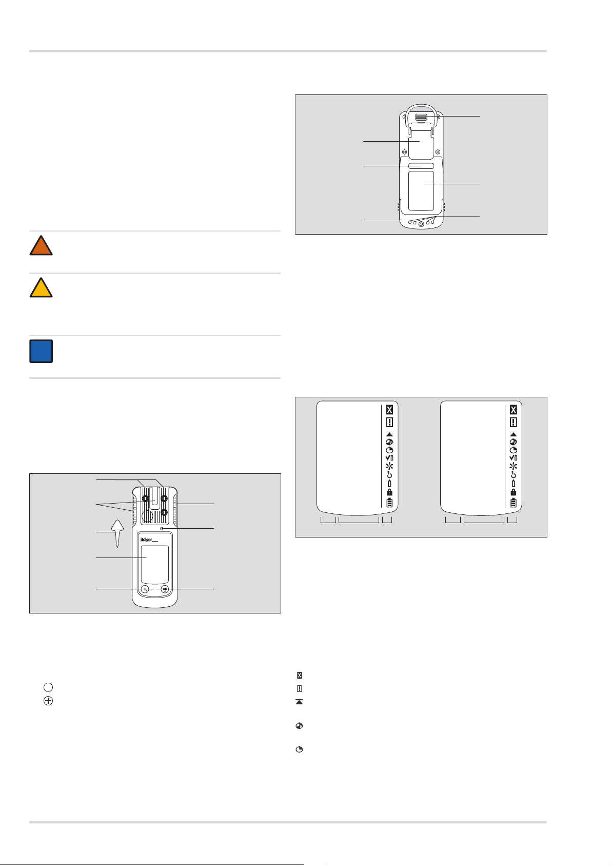
2.1.2 Rear side
1
IR interface
2
Fastening clip
3
Nameplate
4
Charging contacts
5
Power pack
6
Serial no.
2.1.3 Display
2 Description
2.1 Product overview
2.1.1 Front
Left: 4 measuring channels, right: 3 measuring channels
1
Measured gas display
2
Measuring value display with unit
3
Special symbols
The following only shows the instrument version with
4 measuring channels.
1
Gas entry
2
Alarm LED
3
Horn
4
key
5
key
6
Display
7
Tool for changing sensor
4 Dräger X-am 2500
2.1.4 Special symbols
Fault message, see section 4.1 on page 15
Warning message, see section 4.1 on page 15
Display of peak values for all measured gases,
see section 4.1 on page 15
The exposure evaluation display (TWA) for measured
gases, e.g. H
The exposure evaluation display (STEL) for measured
gases, e.g. H
S and CO, see section 4.1 on page 15
2
S und CO, see section 4.1 on page 15
2
Description
The instrument is set to the bump test function,
see section 3.4 on page 11
The instrument is set to the fresh air calibration function,
see section 5.2 on page 16
The instrument is set to the 1-button calibration/
adjustment function, see section 5.4 on page 17
The instrument is set to the single gas calibration
function, see section 5.4.1 on page 18
Function for password input is active, see section 4.4
on page 15
Battery / rechargeable battery 100 % full
Battery / rechargeable battery 2/3 full
Battery / rechargeable battery 1/3 full
Battery / rechargeable battery empty
2.2 Intended use
Portable gas detection instrument for the continuous
monitoring of the concentration of several gases in the ambient
air within the working area and in explosion-hazard areas.
Independent measurement of up to 4 gases, in accordance
with the installed Dräger sensors.
Areas subject to explosion hazards, classified by zones
The instrument is intended for the use in explosion-hazard
areas of Zone 0, Zone 1 or Zone 2 or in mines at risk due to fire
damp. It is intended for use within a temperature range of 20 °C to +50 °C, and for areas in which gases of explosion
groups IIA, IIB or IIC and temperature class T3 or T4
(depending on the batteries and rechargeable battery) may be
present. If used in mines, the instrument is only to be used in
areas known to have a low risk of mechanical impact.
Areas subject to explosion hazards, classified by divisions.
The instrument is intended for use in explosion-hazard areas
according to Class I&II, Div. 1 or Div. 2 within a temperature
range of -20 °C to +50 °C, and for areas where gases or dusts
of groups A, B, C, D, E, F, G and temperature class T3 or T4
may be present (depending on the rechargeable battery and
batteries).
NOTICE
i
i
CSA requirement: Only the combustible gas detection
portion of this instrument has been assessed for
performance.
The instrument has not been classified by the CSA for
use in mines.
2.3 Approvals
Copies of the name plate and the declaration of conformity are
provided in the enclosed supplementary documentation (order
no. 90 33 890).
Do not stick anything on the name plate on the gas detector.
The technical approvals are valid for the X-am 2500 gas
detection instrument and the calibration cradle. The explosionprotection approvals are only valid for the X-am 2500 gas
detection instrument; the calibration cradle must not be used in
the Ex zone.
The BVS 10 ATEX E 080 X technical suitability test is based on
the calibration with the target gas.
2.3.1 Safety Instructions
WARNING
!
Do not replace or charge batteries in potentially
explosive areas. Explosion hazard!
Charge the NiMH power pack T4 (type HBT 0000) or
T4 HC (type HBT 0100) with the associated Dräger
charger. Charge NiMH single cells for ABT 0100
battery holder in accordance with the manufacturer’s
specifications. Ambient temperature during the
charging process: 0 to +40 °C.
To reduce the danger of explosion, do not mix new
batteries with old batteries and do not mix batteries
made by different manufacturers.
Always disconnect the instrument from the power pack
before carrying out any maintenance operations.
WARNING
CSA requirement: Measured values over the full scale
value may indicate an explosive atmosphere.
Only applicable to Class II certification. CSA Std.
C22.2 No 152 does not have any requirement for
Class II hazardous locations and therefore this device
has not been performance tested by CSA for Class II.
The sensor may become clogged and not detect gas
properly or warn the user of its inability to detect gas.
WARNING
CSA requirement: The sensitivity must be tested on a
daily basis before first use with a known concentration
of the gas to be measured in accordance with 25 to
50 % of the concentration limit value. The accuracy
must be 0 to +20 % of the actual value. The accuracy
can be corrected via calibration.
Substitution of components may impair intrinsic safety.
Only use power packs ABT 0100 (order no. 83 22 237),
HBT 0000 (order no. 83 18 704) or HBT 0100 (order no.
83 22 244). See marking on power pack for approved
batteries and related temperature classes.
Not tested in an oxygen-enriched atmosphere
(>21 % O
High off-scale readings may indicate an explosive
concentration.
).
2
Dräger X-am 2500 5
Operation
02733366.eps
0 0 0
Ex
%UEG
CO
2
ppm
O
2
Vol%
CO
ppm
H
2S
ppm
Ex
%UEG
CO
2
ppm
O
2
Vol%
CO
ppm
H
2S
ppm
Ex
%UEG
CO
2
ppm
O
2
Vol%
CO
ppm
H
2S
ppm
X-am 2500
X-am 2500 X-am 2500
83 25 736 83 16 639
83 21 849 /
83 21 850
2
1
2
1
2
1
1
3
3
3
Note the following for CSA (Canadian Standards Association)
applications:
For the CSA approval only the functions of the device
component that is used to measure flammable gases are
tested. The device is not approved by CSA for use in mining.
WARNING
Before daily use, test the sensitivity with a known
concentration of the applicable gas corresponding to
25 to 50 % of the maximum concentration. The
accuracy must be within a range of 0 to +20 % of the
actual value. Perform a calibration to correct the
accuracy if necessary.
3 Operation
3.1 Preparations for operation
WARNING
To reduce the risk of ignition of a flammable or
explosive atmosphere, strictly adhere to the following
warning statements: Only use power pack types
ABT 01xx, HBT 00xx or HBT 01xx. See the marking on
the rechargeable battery for permitted rechargeable
batteries and the corresponding temperature class.
The charging time is typically 4 hours.
A new NiMH power pack reaches its full capacity after three
complete charging/discharging cycles.
Never store the instrument for extended periods without
being connected to a power source (maximum of
2 months) because the internal buffer battery will drain.
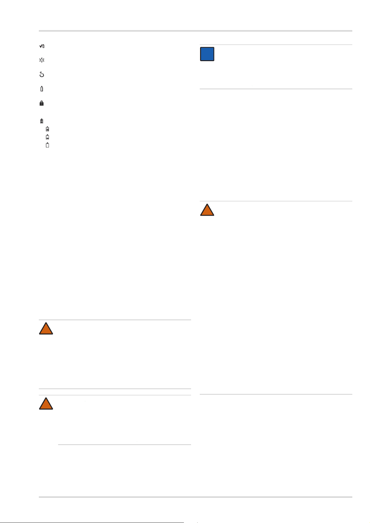
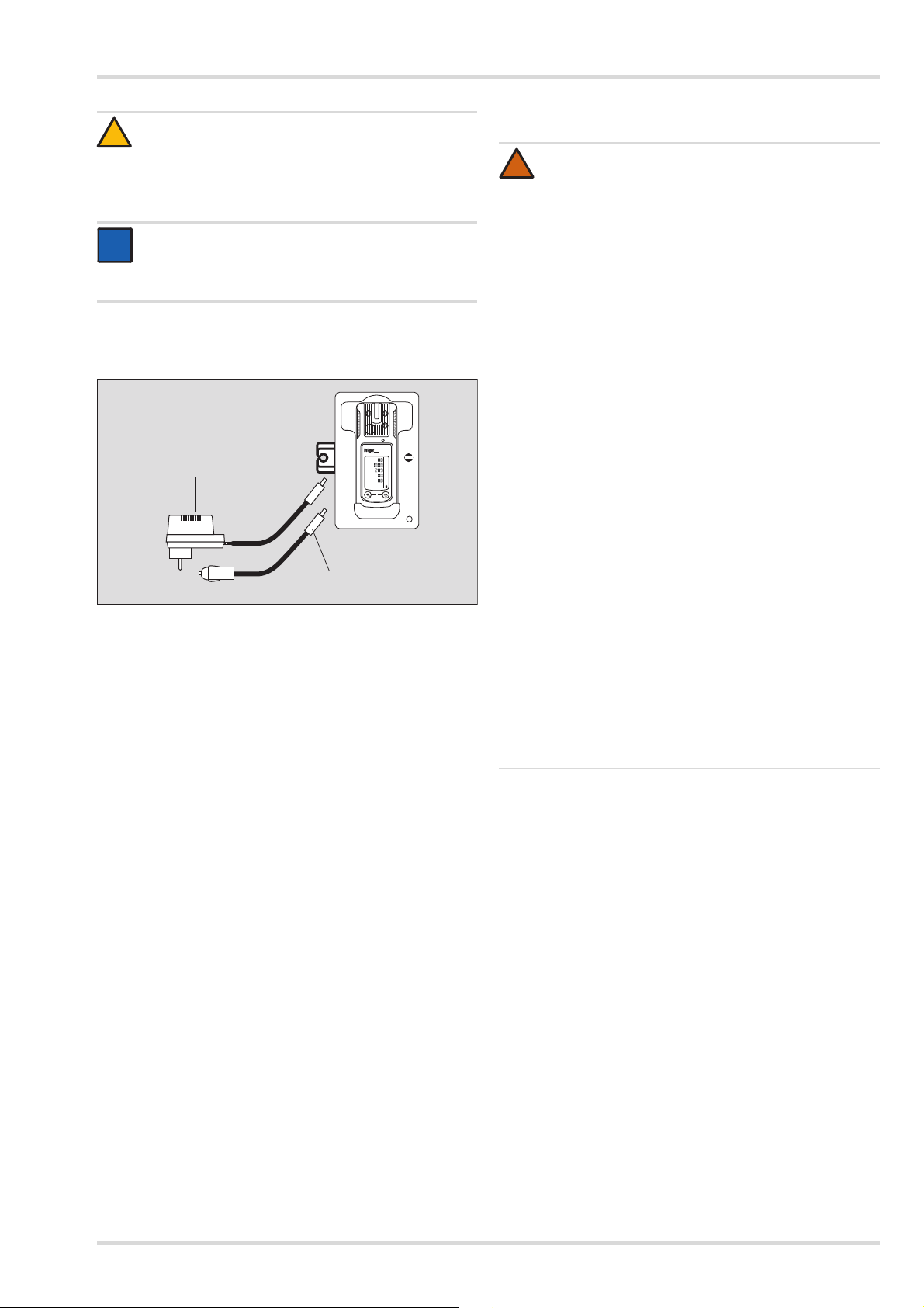
Charging with the charging module adapter and the power
supply unit 83 21 849 or 83 21 850
A maximum of 5 instruments in charging modules (order
no. 83 18 639) can be charged at the same time on the
charging module adapter (order no. 83 25 736) in
connection with the power supply unit (order no.
83 21 849). Up to 20 instruments can be charged at the
same time with the power supply unit 83 21 850.
Before attaching the charging modules to the charging
module adapter, disconnect the power supply unit from the
mains supply!
CAUTION
!
Always connect or disconnect the charging modules
individually and never in groups in order to prevent the
charging module adapter from becoming damaged.
Even during transportation, always handle the power
supply unit and the charging modules individually and
without instruments inserted.
Substitution of components may impair intrinsic safety.
Before using the instrument for the first time, insert a
charged NiMH T4 power pack or batteries approved by
Dräger see section 3.1.2 on page 7.
The instrument is now ready for operation.
3.1.1 Charging the batteries
WARNING
Explosion hazard! To reduce the risk of flammable or
explosive atmospheres igniting, it is essential that the
warning notices below are observed:
Do not charge underground or in explosion hazard areas!
The chargers are not designed in accordance with the
regulations for fire damp and explosion protection.
Charge the NiMH power pack T4 (type HBT 0000) or
T4 HC (type HBT 0100) with the associated Dräger
charger. Charge NiMH single cells for ABT 0100
battery holder in accordance with the manufacturer’s
specifications. Ambient temperature during the
charging process: 0 to +40 °C.
NOTICE
Even if the instrument is not used, Dräger
recommends storing the instrument in the charging
cradle (chargingmodule X-am 1/2/5000, order no.
83 18 639).
To maintain the lifetime of the batteries, charging is
temperature controlled and only performed in a temperature
range of 5 to 35 °C. When outside this temperature range,
the charging automatically interrupted and automatically
recommenced after the temperature range has been
reached again.
Position the instrument on an even and level surface.
1. Turn the slots of the interlock into a horizontal position by
using a screwdriver or coin.
2. Insert the fastening lug (2) of the charger module
(simultaneous power feed) until it engages.
3. Close the lock (1) with a quarter turn (slot is positioned
vertically).
4. Attach additional charging modules in the same way.
5. Connect the power pack to the mains.
The green LED (3) lights up.
6. Insert the switched off instrument into the charger module.
Display LED (3) on the charger module:
Charging
Fault
Full
If a fault occurs:
Remove the instrument from the charging module and
insert it again.
If the fault still occurs, have the charging module repaired.
It takes approx. 4 hours to fully charge an empty
rechargeable battery.
6 Dräger X-am 2500
Operation
02833366.eps
83 16 994 (100 … 240 V)
83 16 997 (100 … 240 V)
45 30 057
0
Ex
%UEG
CO
2
ppm
O
2
Vol%
CO
ppm
H
2S
ppm
X-am 2500
CAUTION
A short circuit of the charging contacts in the charging
modules, e. g., by metallic objects that have fallen in,
does not result in damage to the charging station.
It should, however, be avoided due to possible heating
hazards and incorrect displays on the charger module.
NOTICE
If combining different charging modules, follow the
instructions in the manual supplied with the charging
module adapter.
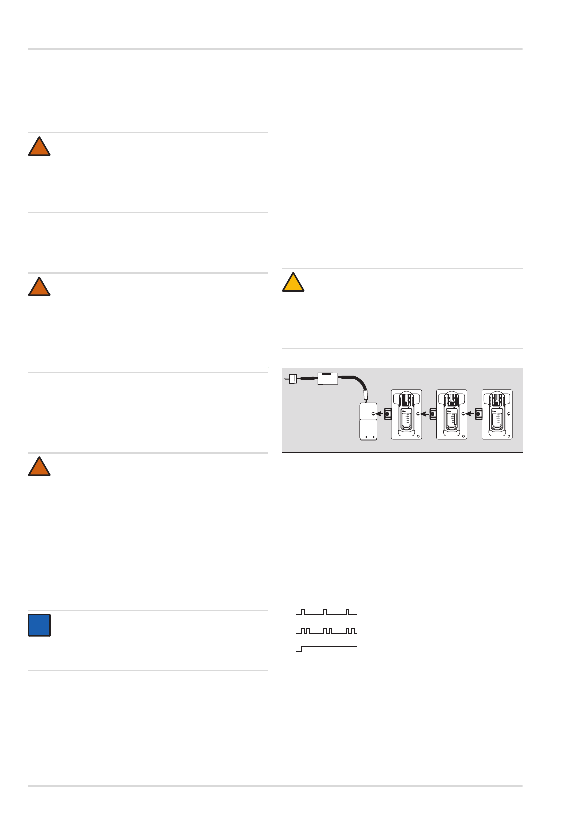
Charge using charger module and plug-in power pack or
vehicle charging adapter
When using the power supply unit (order no. 83 16 994),
up to 5 instruments can be charged at the same time, with
the power supply unit (order no. 83 16 997) one instrument
individually.
When using the vehicle charging adapter (order no.
45 30 057) it is recommended that you supply every
charging module separately.
The charging process is carried out analogous to charging
with the multiple charging station.
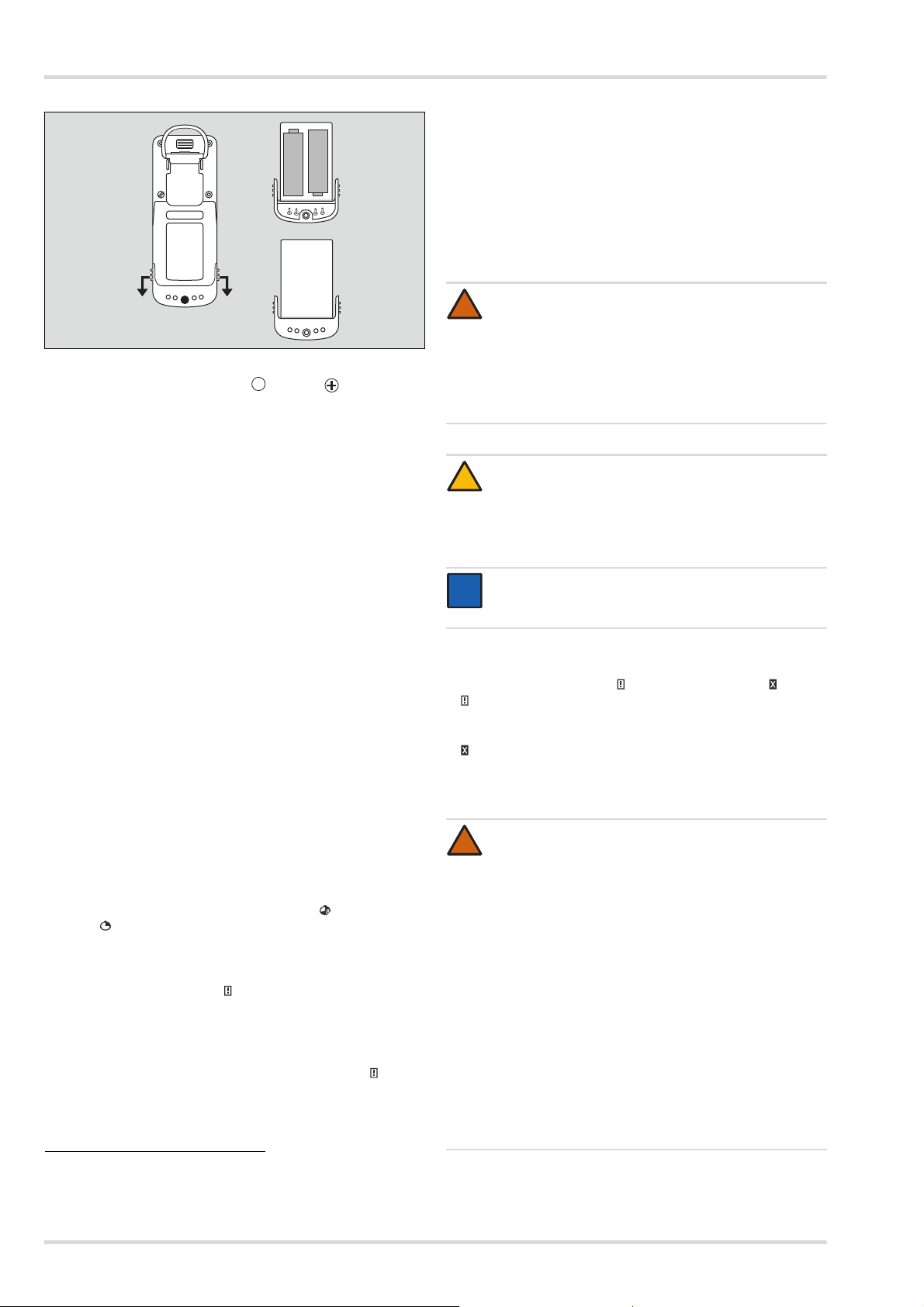
3.1.2 Replacing the batteries / rechargeable batteries
WARNING
!
Explosion hazard! To reduce the risk of flammable or
explosive atmospheres igniting, it is essential that the
warning notices below are observed:
Do not throw used batteries into fire or try to open them
by force.
Do not replace or charge batteries in areas at risk of an
explosion hazard.
Do not mix new batteries with used batteries, and do
not mix batteries from different manufacturers or of
different types.
Remove batteries before maintenance work.
Batteries / rechargeable batteries are part of the
Ex approval.
Only the following types may be used:
Alkaline batteries – T3 – (non rechargeable!)
Panasonic LR6 Powerline
Varta Type 4106
Varta Type 4006
Alkaline batteries – T4 – (non rechargeable!)
Duracell Procell MN1500
MN1500
NiMHy rechargeable batteries – T3 – (rechargeable)
GP 180AAHC
1)
1)
(power one) or
1
(industrial)
1)
, Duracell Plus Power
1
(1800 mAh) max. 40 °C ambient
temperature.
Charge the NiMH power pack T4 (type HBT 0000) or
T4 HC (type HBT 0100) with the associated Dräger
charger. Charge NiMH rechargeable batteries for
battery holder ABT 0100 in accordance with the
manufacturer’s specifications. Ambient temperature
during the charging process: 0 to +40 °C.
1) Not part of the measurement performance tests BVS10 ATEX E 080X
and PFG 10 G 001X.
Dräger X-am 2500 7
Operation
02633366.eps
1
2
3
–
+
–
+
1. Switching off the instrument: key and key are held
down simultaneously.
2. Loosen the screw (2.0 mm hexagon socket) on the power
pack and remove the power pack.
With battery holder (order no. 83 22 237): Replace alkaline
batteries or NiMHy rechargeable batteries. Ensure correct
polarity.
With the T4 NiMH power pack (type HBT 0000) / T4 HC
(type HBT 0100): Completely replace the power pack.
3. Insert the power pack into the instrument and tighten
the screw, the instrument switches on automatically.
After replacing the T4 NiMH power pack (type HBT 0000)/
T4 HC (type HBT 0100), a full charge is recommended.
After the batteries have been replaced:
The settings and data are stored when the battery is replaced.
The sensors warm up again.
3.1.3 Switching on the instrument
1. Hold down the [OK] button for approx. 3 seconds until the
»3.2.1« countdown shown on the display has elapsed.
All the display segments, including the visual, audible
and vibration alarms, are activated for a short time.
The software version is displayed.
The instrument performs a self-test.
The sensor that is up next for calibration/adjustment is
displayed with the remaining days until the next
calibration/adjustment e. g. »Ex%LEL CAL20«.
The time until the bump test interval elapses is
displayed in days, e.g. »bt123«.
All A1 and A2 alarm thresholds and »« (TWA)
»« (STEL)
1
for all toxic gases (e. g. H2S or CO) are
1)
and
displayed consecutively.
During the sensor warm-up phase:
The display for the measured value flashes
The special symbol » « is displayed.
No alarms are issued during the warm-up phase.
The red LEDs flash.
The gas detector is ready to measure when the
measured values no longer flash and the red LEDs are
no longer illuminated. The special symbol » « may
continue to be displayed if corresponding warnings
(e.g. not yet ready for calibration) are active.
2. Press the [OK] key to cancel the display of the activation
sequence.
1) Only when activated in the instrument configuration. Delivery
condition: not activated.
3.1.4 Switching off the instrument
Press and hold the [OK] key and [+] key simultaneously
until the countdown »3.2.1« shown on the display has
elapsed.
When the instrument is switched off, the visual, audible and
vibration alarms are activated for a short time in order to
protect against inadvertent switch off.
3.2 Before entering the workplace
WARNING
!
Before any measurements relevant to safety are
made, check the adjustment with a bump test, adjust if
necessary and check all alarm elements. If national
regulations apply, a bump test must be performed
according to the national regulations. Faulty
adjustment may result in incorrect measuring results,
with possible serious consequences.
CAUTION
!
The CatEx sensor is intended for measurements of
flammable gases and vapours mixed with air (i.e. O
content ≈ 21 vol.%). Incorrect measured values may
be displayed in the case of oxygen deficient or oxygen
enriched environments.
NOTICE
i
i
If the gas detector is used for offshore applications, a
distance of 5 m to a compass must be complied with.
1. Switch on the instrument. The current measured values are
shown in the display.
2. Observe any warning »« or fault messages »«.
The instrument can be operated normally. If the warning
message does not disappear automatically during operation,
the instrument must be serviced after the end of use.
The instrument is not ready to measure and requires
maintenance.
3. Check that the gas inlet opening on the instrument is
not covered.
WARNING
!
Explosion hazard! To reduce the risk of flammable or
explosive atmospheres igniting, it is essential that the
warning notices below are observed:
Fractions of catalytic poisons in the measuring gas
(e.g. volatile silicone, sulphur, heavy metal
compounds or halogenated hydrocarbon) can
damage the CatEx sensor. If the CatEx sensor can
no longer be calibrated to the target concentration,
the sensor must be replaced.
In case of measurements in an oxygen-deficient
atmosphere (<12 Vol.-% O
may show incorrect displays; in this case, a reliable
) the CatEx sensor
2
measurement with a CatEx sensor is not possible.
In an oxygen enriched atmosphere (>21 vol. %
O
), the explosion protection cannot be
2
guaranteed; remove instrument from the Ex area.
High values outside the display area indicate an
explosive concentration where applicable.
2
8 Dräger X-am 2500
3.3 Configuration
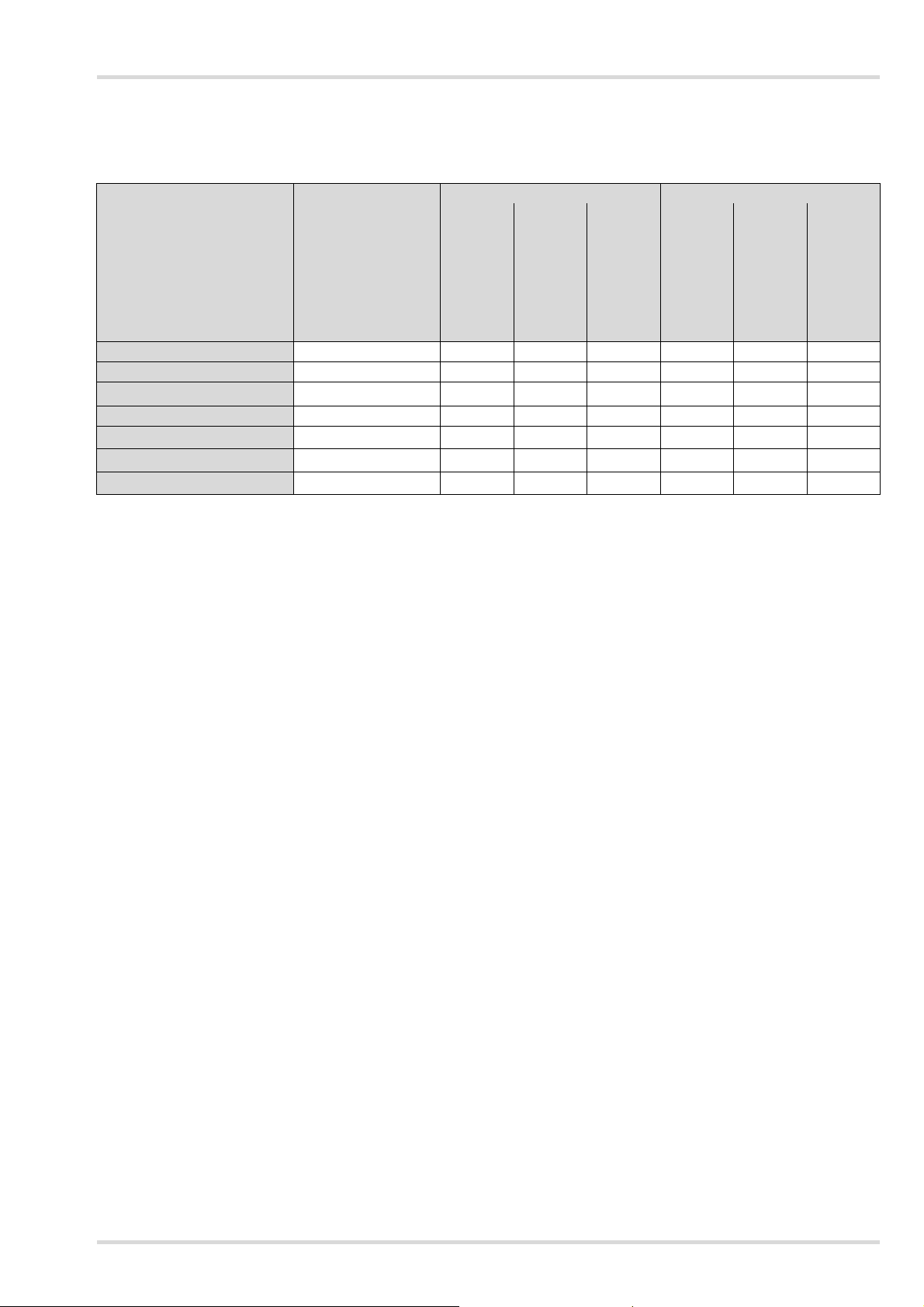
3.3.1 Standard gas configuration
Operation
DrägerSensor Measuring range
1)
threshold
Alarm A1
can be acknowledged
1)
self-latching
threshold
Alarm A2
can be acknowledged
1)
self-latching
CatEx 125 PR [%LEL] 0 to 100 20 yes no 40 no yes
CatEx 125 PR Gas [%LEL] 0 to 100 20 yes no 40 no yes
XXS O2 [Vol.-%] 0 to 25
19
2)
no yes 23 no yes
XXS CO LC [ppm] 0 to 2000 30 yes no 60 no yes
XXS H2S LC [ppm] 0 to 100 5 yes no 10 no yes
XXS NO2 [ppm] 0 to 50 5 yes no 10 no yes
XXS SO2 [ppm] 0 to 100 0.5 yes no 1 no yes
1) Different settings can be selected to meet customer requirements on delivery. The current setting can be checked and changed with
the Dräger CC Vision software.
A version of the CC-Vision software that can be used for Dräger X-am 2500 is available for download from the product page for the X-am 2500
at the following web address: www.draeger.com
2) With O
, A1 is the lower alarm threshold: an alarm is triggered if the value is too low.
2
Dräger X-am 2500 9
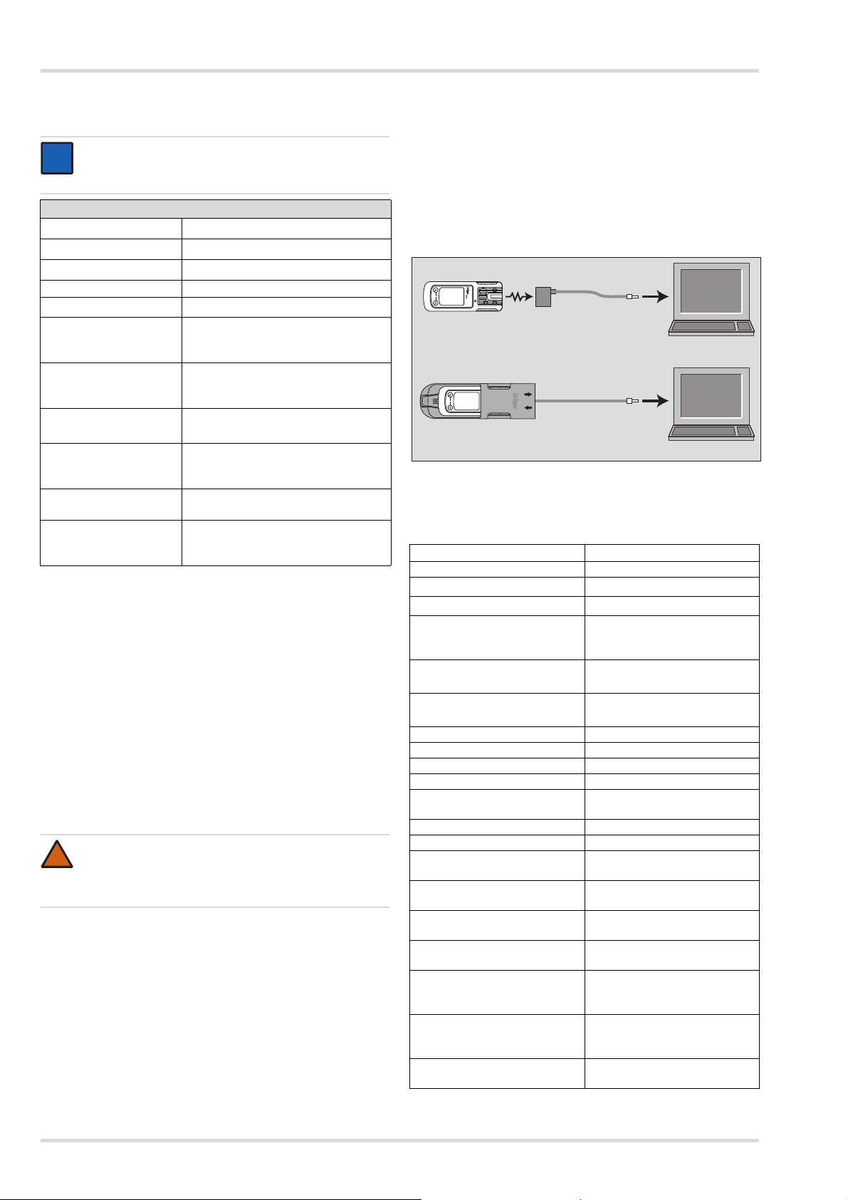
Operation
IR
Calibration cradle (order no. 83 18 752)
with inserted
USB DIRA with USB cable (order no. 83 17 409)
USB DIRA with USB cable
(order no. 83 17 409)
USB 2.0
USB 2.0
0
0
X-am 2500
3.3.2 Standard instrument configuration
NOTICE
Only trained persons are permitted to carry out
modifications to the instrument configuration.
2)
2) 3)
1)
Extended bump test
2)
ON
ON
Dräger X-am® 2500
Bump test mode
Fresh air calibration
Operating signal
Capture range ON
Switch off
LEL factor
2)
2)
(ch4)
2) 4) 5)
STEL
(short-term average)
2) 5) 6)
TWA
(shift average)
Alarm A1
7)
(4.4 vol. % corresponds to
STEL function — disabled
Average value duration =
TWA function — disabled
Average value duration = 8 hours
can be acknowledged, non-latching,
allowed
4.4 (vol. %)
100 %LEL)
15 minutes
pre-alarm,
rising flank
Alarm A1 at O
Alarm A2
sensor cannot be acknowledged, latching,
2
7)
like main alarm, falling flank
cannot be acknowledged, latching,
main alarm,
rising flank
1) X-am® is a registered trademark of Dräger.
2) Different settings can be selected to meet customer requirements
on delivery. The current setting can be checked and changed with
the Dräger CC Vision software.
3) A periodic short flashing indicates the operating capacity of the
instrument. If there is no operating signal, correct operation cannot
be guaranteed.
4) STEL: average value of an exposure over a short period, generally
15 minutes.
5) Interpretation only if the sensor is designed for this.
6) TWA: shift averages are workplace limit values for generally eight
hours per day of exposure for five days a week during a working life.
7) Latching and acknowledgement of alarms A1 and A2 can be
configured with the Dräger CC Vision PC software.
Changing the configuration: see “Replacing the sensors” on
page 20.
WARNING
After a basic initialization has been carried out with the
PC software Dräger CC Vision, individual alarm
settings may have been changed.
Selecting or disabling the capture ranges (only applies for
the measuring mode):
The capture range is selected in the measuring mode (factory
setting) and permanently disabled in calibration mode.
The CC-Vision PC software can be used to select or disable
the capture ranges for the measuring mode.
3.3.3 Configuring the device
To individually configure a instrument with standard
configuration, the instrument must be connected with a PC.
The installed PC software Dräger CC Vision is used for
configuration. The PC software Dräger CC Vision can be
downloaded from the following web address free of charge:
www.draeger.com/software.
Observe the documentation and online help for the
software.
Device settings
The following changes can be made to the device parameters
for a device:
Designation Field
Password Numeric field (3-figure)
Operating signal LED
Operating signal horn
1)
1)
Yes/ No
Yes/ No
Switch-off mode “Switch off permitted” or
“Switch off prohibited” or
“Switch off prohibited at A2”
Shift length (TWA) 2) (in
minutes)
Short-term exposure limit
3) 4)
(STEL)
(in minutes)
60 — 1440
(setting for exposure alarm)
0 — 15
(setting for exposure alarm)
User ID(12 characters) Alphanumeric field
Switch database on or off On/Off
Overwrite database Yes/No
Database mode Peak/Average
Database interval
1 s / 10 s / 30 s / 1 min / 2 min /
5 min / 10 min / 30 min
Date (date on the PC)
Time (time on the PC)
Warning after expiry of
Yes/ No
calibration interval
Error after expiry of calibration
Yes/ No
interval
Delay until error after expiry of
0 — 10
calibration interval (days)
Automatic detection of Bump
Yes/ No
Test Station
Activate sensitivity calibration
following negative bump test
Yes/No (relates only to a
device connected to the
Dräger Bump Test Station)
Bump test mode “extended bump test” or “quick
bump test” or “bump test
deactivated”
Warning after expiry of bump
Yes/ No
test interval
10 Dräger X-am 2500
Loading…
Газоанализатор Drager X-am 2500
- Позволяет измерять от 1 до 4 газов
- для персонального контроля воздуха
- обнаружение легковоспламеняющихся газов и паров, а также O2, CO, NO2, SO2 и H2S
Долговечные электрохимические сенсоры
Сенсоры компании Dräger серии XXS предназначены для определения концентрации CO (угарный газ), H2S, O2, SO2 и NO2 и обеспечивают безопасную работу на промышленных, горнодобывающих и нефтеперерабатывающих предприятиях. Сенсор на сероводород высокого разрешения позволяет надежно измерять ПДК на рабочем месте даже при очень низких концентрациях газа. Экономичный сенсор на кислород не содержит свинца и отличается длительным сроком службы — более пяти лет. Такой же срок службы имеют и сенсоры Dräger на CO и H2S, что позволяет значительно снизить эксплуатационные затраты.
Устойчивый к отравлению сенсор взрывоопасных газов
Новый каталитический сенсор взрывоопасных газов (CatEx-сенсор) обладает повышенной устойчивостью к таким отравителям, как силикон и сероводород. Высокая стабильность обеспечивает длительный срок службы — более четырех лет. Чувствительность к горючим газам и парам подтверждена сертификатом на измерительные характеристики по IEC/EN 60079-29-1 от метана до нонана. Этот сертификат также подтверждает пригодность устройства к применению в взрывоопасной зоне, например, на нефтеперерабатывающих заводах и в химической промышленности.
X-am 2500 — Максимальная безопасность
Драгер X-am 2500 аттестован по взрывозащите для зоны 0, т.е. предназначен для обеспечения высокого уровня безопасности пользователя во взрывоопасных зонах. Конструкция устройства обеспечивает возможность поступления газа сверху и спереди.
Техническое обслуживание: быстро, просто, недорого
От функциональной проверки до подробной документации — станция для функциональной проверки Dräger Bump Test Station, не требующая локального источника питания, и автоматическая станция тестирования и калибровки Dräger X-dock идеально дополняют систему и экономит ваше время. Благодаря Dräger X-dock, испытание сенсоров Dräger проходят за 8–15 секунд1 при низком потреблении газа. Это значительно сокращает эксплуатационные расходы.
1 Со стандартными датчиками: CH4, O2, CO, H2S
Режимы «Диффузия» и «Насос»
Опциональный внешний насос с шлангом длиной до 45 м позволяет использовать прибор для контрольных замеров в резервуарах и колодцах или для поиска утечек. Насос запускается автоматически при подключении прибора. Возможно быстрое и простое переключение между режимами «Диффузия» и «Насос» без дополнительных инструментов.
Драгер х ам 2500 — Прочный и эргономичный
Благодаря малому весу Драгер X-am 2500 удобно носить с собой. Простое управление и навигация по меню осуществляется двумя кнопками, что делает использование сигнализатора интуитивно понятным, несмотря на его многофункциональность. Резиновое покрытие и противоударные датчики обеспечивают дополнительную защиту прибора при ударах или вибрации. Кроме того, Драгер X-am 2500 нечувствителен к воздействию электромагнитного излучения, например, от беспроводных устройств. Dräger X-am 2500 обладает пылевлагозащитой в соответствии с IP 67, поэтому полностью сохраняет работоспособность даже при случайном попадании в воду.
Надежный источник питания
Сигнализатор Dräger X-am 2500 может работать со щелочными или NiMH аккумуляторами. Это обеспечивает надежное электропитание более 12 часов. В зависимости от требований, батареи могут заряжаться в мастерской или в автомобиле. Стандартное время работы без сенсора взрывоопасных газов — более 250 часов.
Ключевые особенности X-am 2500:
- Включает в себя аккумулятор и зарядный комплект.
- Результаты регистрации данных можно получить через ИК-интерфейс.
- Длительный срок службы датчиков.
- До 1000 часов данных могут быть сохранены.
- Плавно переключайтесь между диффузионным и прокачиваемым режимом.
- Доступен внешний насос (продается отдельно).
- Срок службы батареи: 12 часов с 6-часовой перезарядкой.
- Степень защиты: IP67.
Купить газоанализатор Драгер недорого просто, достаточно нажать «в корзину». Цена газоанализатора низкая с официальной доставкой на сайте по Москве и РФ.
Эксплуатация прибора
4.2
Включение прибора
1. Нажмите и удерживайте кнопку [OK] примерно 3 секунды,
пока над дисплее не пройдет обратный отсчет » 3 . 2 . 1 «.
Кратковременно загораются все элементы дисплея; для
проверки работоспособности поочередно включаются
сигнальный светодиод, звуковое сигнальное устройство
и вибросигнал.
Будет показан номер версии программного обеспечения.
Выполняется самотестирование прибора.
Будет показано время до следующей калибровки в днях /
настройки для данного сенсора, напр., ch4 %UEG CAL 20.
Будет показано время до следующей функциональной
проверки в днях, напр., bt 123.
На дисплей поочередно будут выведены пороги тревог A1
и A2, а также
(TWA)
газов (например, H
S или CO).
2
При
разгонке
сенсоров
измерения на дисплее мигает, и показан специальный
символ
(для предупреждения). При разгонке сенсоров
тревоги не активируются.
2. Нажмите кнопку OK, чтобы не выводить на дисплей
последовательность активации.
4.3
Выключение прибора
Одновременно нажмите и удерживайте кнопки OK и [+],
пока на дисплее не пройдет обратный отсчет 3 . 2 . 1 .
В ходе выключения будет подан короткий звуковой, световой
и вибросигнал.
1)
Только когда активировано в конфигурации прибора. Заводская настройка:
не активировано.
224
1
1
и
(STEL)
для всех токсичных
соответствующий
результат
4.4
Перед приходом на рабочее место
Включите прибор. На дисплее будут показаны текущие результаты измерения.
ОСТОРОЖНО
!
Перед проведением измерений, от которых зависит
безопасность людей, проверьте калибровку с помощью
функциональной проверки (Bump Test). При необходимости
откорректируйте калибровку и проверьте все элементы
сигнализации. При выполнении функциональной проверки
соблюдайте государственные нормативы (при их наличии).
Неправильная калибровка может привести к неправильным
результатам измерения, и, как следствие, причинению
вреда здоровью.
ОСТОРОЖНО
!
В обогащенной кислородом атмосфере (>21 об. % O
взрывобезопасность
гарантирована,
поэтому
взрывоопасной области.
ВНИМАНИЕ
!
Сенсор CatEx предназначен для измерения горючих газов
и паров в смеси с воздухом (т.е. с содержанием O
21 об. %). В средах с недостатком или избытком кислорода
прибор может показывать неправильные значения.
1. Включите прибор. На дисплее будут показаны текущие
результаты измерения.
2. Обращайте внимание на любые символы предупреждения
или сообщения о неисправности
Инструмент еще можно использовать обычным образом.
Значок должен исчезнуть в течение рабочей смены,
в противном случае требуется техническое обслуживание.
Инструмент не готов к использованию, требуется техническое
обслуживание.
3. Убедитесь, что впускной порт прибора ничем не закрыт / или
не загрязнен.
при
работе
с
прибором
уберите
прибор
.
Dräger X-am 2500
)
2
не
из
≈
2