

To reduce the impacts on global warming, the packaging materials of this product
are recyclable and reusable. GIGABYTE works with you to protect the environment.
For more product details, please visit GIGABYTE’s website.
A520M S2H
User’s Manual
Rev. 1001
Copyright
© 2020 GIGA-BYTE TECHNOLOGY CO., LTD. All rights reserved.
The trademarks mentioned in this manual are legally registered to their respective owners.
Disclaimer
Information in this manual is protected by copyright laws and is the property of GIGABYTE.
Changes to the specications and features in this manual may be made by GIGABYTE without
prior notice. No part of this manual may be reproduced, copied, translated, transmitted, or
published in any form or by any means without GIGABYTE’s prior written permission.
In order to assist in the use of this product, carefully read the User’s Manual.
For product-related information, check on our website at: https://www.gigabyte.com
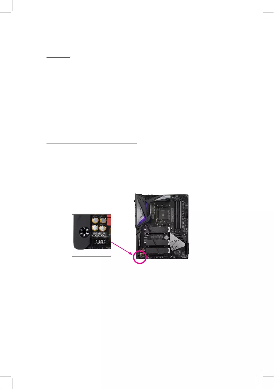
Identifying Your Motherboard Revision
The revision number on your motherboard looks like this: «REV: X.X.» For example, «REV:
1.0″ means the revision of the motherboard is 1.0. Check your motherboard revision before
updating motherboard BIOS, drivers, or when looking for technical information.
Example:

— 3 —
Table of Contents
A520M S2H Motherboard Layout …………………………………………………………………………4
Chapter 1 Hardware Installation ………………………………………………………………………….5
1-1 Installation Precautions ………………………………………………………………………… 5
1-2 Product Specications ………………………………………………………………………….. 6
1-3 Installing the CPU ……………………………………………………………………………….. 9
1-4 Installing the Memory …………………………………………………………………………… 9
1-5 Installing an Expansion Card ………………………………………………………………. 10
1-6 Back Panel Connectors ………………………………………………………………………. 10
1-7 Internal Connectors ……………………………………………………………………………. 12
Chapter 2 BIOS Setup ……………………………………………………………………………………..20
2-1 Startup Screen ………………………………………………………………………………….. 20
2-2 The Main Menu …………………………………………………………………………………. 21
2-3 Favorites (F11) ………………………………………………………………………………….. 22
2-4 Tweaker ……………………………………………………………………………………………. 23
2-5 Settings ……………………………………………………………………………………………. 26
2-6 System Info. ……………………………………………………………………………………… 32
2-7 Boot …………………………………………………………………………………………………. 33
2-8 Save & Exit ……………………………………………………………………………………….. 36
Chapter 3 Appendix …………………………………………………………………………………………37
3-1 Conguring a RAID Set ………………………………………………………………………. 37
3-2 Drivers Installation ……………………………………………………………………………… 39
Regulatory Notices ………………………………………………………………………………………. 40
Contact Us …………………………………………………………………………………………………. 41
— 4 —
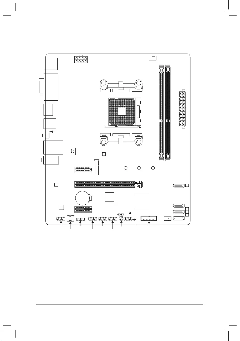
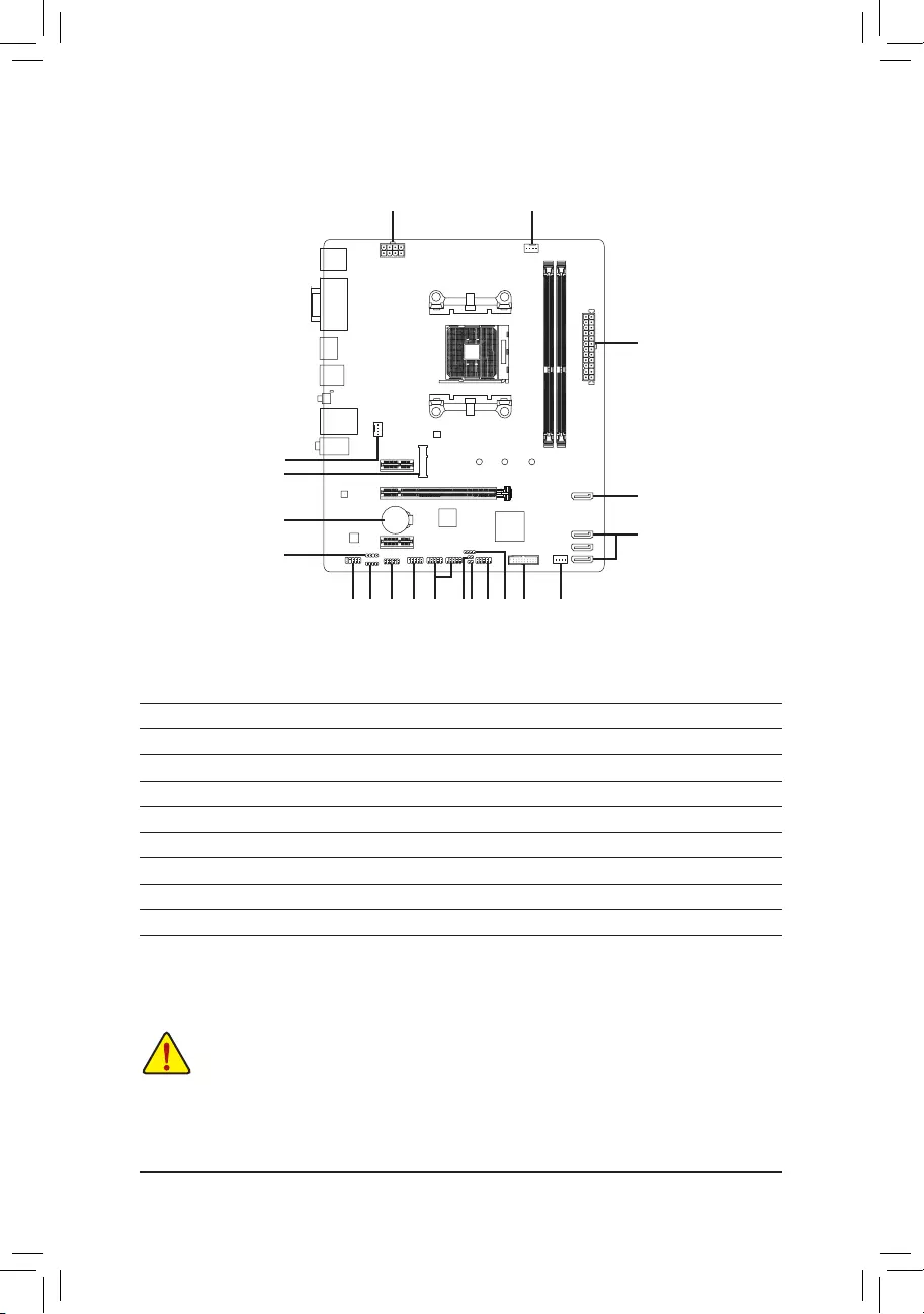
A520M S2H Motherboard Layout
* The box contents above are for reference only and the actual items shall depend on the product package you obtain.
The box contents are subject to change without notice.
Box Contents
5A520M S2H motherboard 5Two SATA cables
5Motherboard driver disc 5I/O Shield
5User’s Manual
KB_MS_USB
HDMI
AUDIO
CPU_FAN
SYS_FAN1
ATX
A520M S2H
DDR4_A1
DDR4_B1
BAT
U32
CODEC
M_BIOS
VGA
DVI
PCIEX16
PCIEX1_1
PCIEX1_2
iTE® Super
I/O
Realtek®
GbE LAN
F_U32
CI
SPEAKER
F_USB1 F_PANEL
F_USB2TPM
D_LED1
SATA3
012
U32_LAN
Socket AM4
3
CLR_CMOSF_AUDIO
M2A_CPU 806042
SATA3
SYS_FAN2
COMLED_C
QFLASH_PLUS
QFLED
ATX_12V
AMD
A520

Chapter 1 Hardware Installation
1-1 Installation Precautions
The motherboard contains numerous delicate electronic circuits and components which can become
damaged as a result of electrostatic discharge (ESD). Prior to installation, carefully read the user’s
manual and follow these procedures:
•Prior to installation, make sure the chassis is suitable for the motherboard.
•Prior to installation, do not remove or break motherboard S/N (Serial Number) sticker or
warranty sticker provided by your dealer. These stickers are required for warranty validation.
•Always remove the AC power by unplugging the power cord from the power outlet before
installing or removing the motherboard or other hardware components.
•When connecting hardware components to the internal connectors on the motherboard, make
sure they are connected tightly and securely.
•When handling the motherboard, avoid touching any metal leads or connectors.
•It is best to wear an electrostatic discharge (ESD) wrist strap when handling electronic
components such as a motherboard, CPU or memory. If you do not have an ESD wrist strap,
keep your hands dry and rst touch a metal object to eliminate static electricity.
•Prior to installing the motherboard, please have it on top of an antistatic pad or within an
electrostatic shielding container.
•Before connecting or unplugging the power supply cable from the motherboard, make sure
the power supply has been turned off.
•Before turning on the power, make sure the power supply voltage has been set according to
the local voltage standard.
•Before using the product, please verify that all cables and power connectors of your hardware
components are connected.
•To prevent damage to the motherboard, do not allow screws to come in contact with the
motherboard circuit or its components.
•Make sure there are no leftover screws or metal components placed on the motherboard or
within the computer casing.
•Do not place the computer system on an uneven surface.
•Do not place the computer system in a high-temperature or wet environment.
•Turning on the computer power during the installation process can lead to damage to system
components as well as physical harm to the user.
•If you are uncertain about any installation steps or have a problem related to the use of the
product, please consult a certied computer technician.
•If you use an adapter, extension power cable, or power strip, ensure to consult with its installation
and/or grounding instructions.
— 5 —
1-2 ProductSpecications
CPU AMD Socket AM4, support for:
3rd Generation AMD Ryzen™ processors/
3rd Generation AMD Ryzen™ with Radeon™ Graphics processors
(Go to GIGABYTE’s website for the latest CPU support list.)
Chipset AMD A520
Memory 2 x DDR4 DIMM sockets supporting up to 64 GB (32 GB single DIMM capacity)
of system memory
Support for DDR4 3200/2933/2667/2400/2133 MHz memory modules
Dual channel memory architecture
Support for ECC Un-buffered DIMM 1Rx8/2Rx8 memory modules
Support for non-ECC Un-buffered DIMM 1Rx8/2Rx8/1Rx16 memory modules
Support for Extreme Memory Prole (XMP) memory modules
(Go to GIGABYTE’s website for the latest supported memory speeds and memory
modules.)
Onboard
Graphics
Integrated in the 3rd Generation AMD Ryzen™ with Radeon™ Graphics processors:
— 1 x D-Sub port, supporting a maximum resolution of 1920×1200@60 Hz
— 1 x DVI-D port, supporting a maximum resolution of 1920×1200@60 Hz
* The DVI-D port does not support D-Sub connection by adapter.
— 1 x HDMI port, supporting a maximum resolution of 4096×2160@60 Hz
* Support for HDMI 2.1 version, HDCP 2.3, and HDR.
Support for up to 3 displays at the same time
Maximum shared memory of 16 GB
Audio Realtek® ALC887 codec
High Denition Audio
2/4/5.1/7.1-channel
* To congure 7.1-channel audio, you need to open the audio software and select Device
advanced settings > Playback Device to change the default setting rst. Please visit
GIGABYTE’s website for details on conguring the audio software.
LAN Realtek® GbE LAN chip (1000 Mbit/100 Mbit)
Expansion Slots CPU:
— 1 x PCI Express x16 slot, supporting PCIe 3.0 and running at x16
Chipset:
— 2 x PCI Express x1 slots, supporting PCIe 3.0
Storage Interface CPU:
— 1 x M.2 connector (Socket 3, M key, type 2242/2260/2280 SATA and PCIe
3.0 x4/x2 SSD support)
Chipset:
— 4 x SATA 6Gb/s connectors
— Support for RAID 0, RAID 1, and RAID 10
— 6 —
USB CPU:
— 4 x USB 3.2 Gen 1 ports on the back panel
Chipset:
— 2 x USB 3.2 Gen 1 ports available through the internal USB header
— 6 x USB 2.0/1.1 ports (2 ports on the back panel, 4 ports available through
the internal USB headers)
Internal
Connectors
1 x 24-pin ATX main power connector
1 x 8-pin ATX 12V power connector
1 x CPU fan header
2 x system fan headers
1 x addressable LED strip header
1 x RGB LED strip header
1 x M.2 Socket 3 connector
4 x SATA 6Gb/s connectors
1 x front panel header
1 x front panel audio header
1 x USB 3.2 Gen 1 header
2 x USB 2.0/1.1 headers
1 x Trusted Platform Module (TPM) header (2×6 pin, for the GC-TPM2.0_S
module only)
1 x serial port header
1 x speaker header
1 x chassis intrusion header
1 x Clear CMOS jumper
Back Panel
Connectors
1 x PS/2 keyboard/mouse port
1 x D-Sub port
1 x DVI-D port
1 x HDMI port
4 x USB 3.2 Gen 1 ports
2 x USB 2.0/1.1 ports
1 x RJ-45 port
1 x Q-Flash Plus button
3 x audio jacks
I/O Controller iTE® I/O Controller Chip
Hardware
Monitor
Voltage detection
Temperature detection
Fan speed detection
Overheating warning
Fan fail warning
Fan speed control
* Whether the fan speed control function is supported will depend on the fan you install.
— 7 —
BIOS 1 x 128 Mbit ash
Use of licensed AMI UEFI BIOS
PnP 1.0a, DMI 2.7, WfM 2.0, SM BIOS 2.7, ACPI 5.0
Unique Features Support for APP Center
* Available applications in APP Center may vary by motherboard model. Supported
functions of each application may also vary depending on motherboard specications.
— @BIOS
— EasyTune
— Fast Boot
— Game Boost
— ON/OFF Charge
— RGB Fusion
— Smart Backup
— System Information Viewer
Support for Q-Flash Plus
Support for Q-Flash
Support for Xpress Install
Bundled
Software
Norton® Internet Security (OEM version)
Realtek® 8118 Gaming LAN Bandwidth Control Utility
Operating
System Support for Windows 10 64-bit
Form Factor Micro ATX Form Factor; 24.4cm x 20.5cm
* GIGABYTE reserves the right to make any changes to the product specications and product-related information without
prior notice.
Please visit GIGABYTE’s website
for support lists of CPU, memory
modules, SSDs, and M.2 devices.
Please visit the Support\Utility List
page on GIGABYTE’s website to
download the latest version of apps.
— 8 —
1-3 Installing the CPU
Please visit GIGABYTE’s website for details on hardware installation.
1-4 Installing the Memory
Read the following guidelines before you begin to install the memory:
•Make sure that the motherboard supports the memory. It is recommended that memory of the same
capacity, brand, speed, and chips be used.
(Go to GIGABYTE’s website for the latest supported memory speeds and memory modules.)
•Always turn off the computer and unplug the power cord from the power outlet before installing the
memory to prevent hardware damage.
•Memory modules have a foolproof design. A memory module can be installed in only one direction.
If you are unable to insert the memory, switch the direction.
DualChannelMemoryConguration
This motherboard provides two memory sockets and supports Dual Channel Technology. After the memory
is installed, the BIOS will automatically detect the specications and capacity of the memory. Enabling Dual
Channel memory mode will double the original memory bandwidth.
The two memory sockets are divided into two channels and each channel has one memory socket as following:
Channel A: DDR4_A1
Channel B: DDR4_B1
Read the following guidelines before you begin to install the CPU:
•Make sure that the motherboard supports the CPU.
(Go to GIGABYTE’s website for the latest CPU support list.)
•Always turn off the computer and unplug the power cord from the power outlet before installing the
CPU to prevent hardware damage.
•Locate the pin one of the CPU. The CPU cannot be inserted if oriented incorrectly.
•Apply an even and thin layer of thermal grease on the surface of the CPU.
•Do not turn on the computer if the CPU cooler is not installed, otherwise overheating and damage
of the CPU may occur.
•Set the CPU host frequency in accordance with the CPU specications. It is not recommended
that the system bus frequency be set beyond hardware specications since it does not meet the
standard requirements for the peripherals. If you wish to set the frequency beyond the standard
specications, please do so according to your hardware specications including the CPU, graphics
card, memory, hard drive, etc.
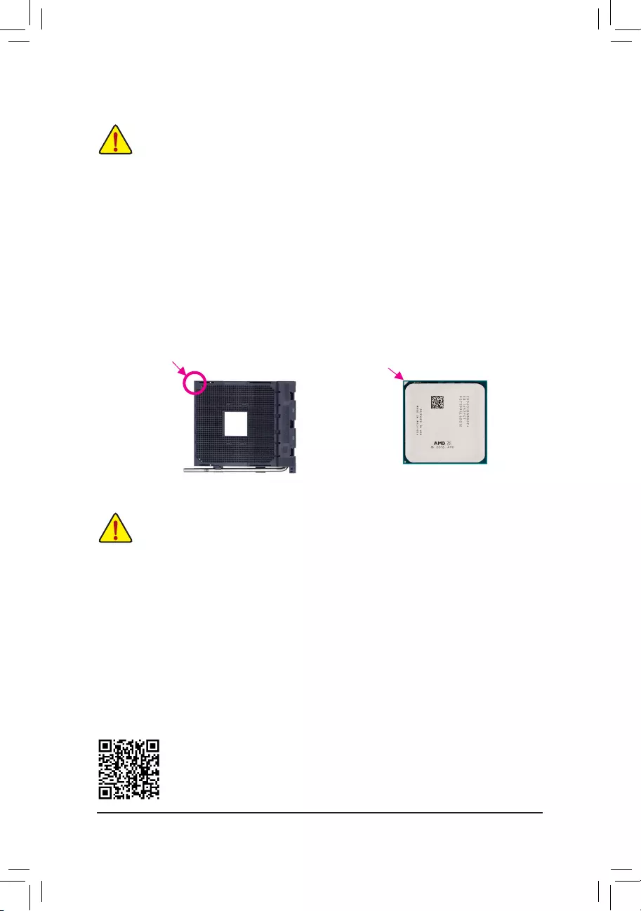
Installing the CPU
Locate the pin one (denoted by a small triangle) of the CPU socket and the CPU.
AM4 Socket
A Small Triangle
Marking Denotes Pin
One of the Socket AM4 CPU
A Small Triangle
Marking Denotes CPU
Pin One
— 9 —
Due to CPU limitations, read the following guidelines before installing the memory in Dual Channel mode.
1. Dual Channel mode cannot be enabled if only one memory module is installed.
2. When enabling Dual Channel mode with two memory modules, it is recommended that memory of
the same capacity, brand, speed, and chips be used.
1-5 Installing an Expansion Card
Read the following guidelines before you begin to install an expansion card:
•Make sure the motherboard supports the expansion card. Carefully read the manual that came
with your expansion card.
•Always turn off the computer and unplug the power cord from the power outlet before installing an
expansion card to prevent hardware damage.
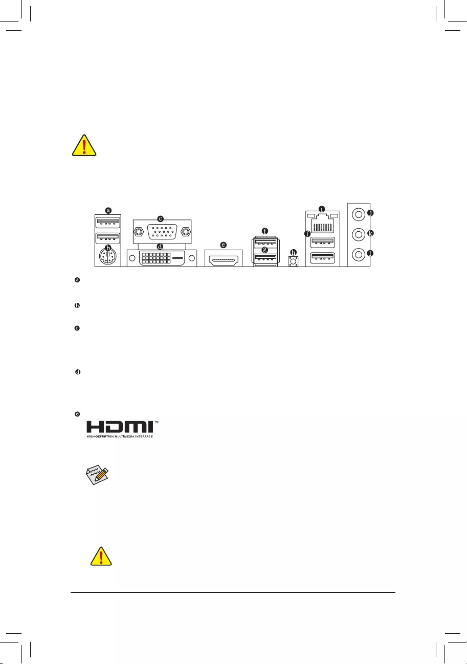
1-6 Back Panel Connectors
USB 2.0/1.1 Port
The USB port supports the USB 2.0/1.1 specication. Use this port for USB devices.
PS/2 Keyboard/Mouse Port
Use this port to connect a PS/2 mouse or keyboard.
D-Sub Port (Note 1)
The D-Sub port supports a 15-pin D-Sub connector and supports a maximum resolution of 1920×1200@60 Hz
(the actual resolutions supported depend on the monitor being used). Connect a monitor that supports D-Sub
connection to this port.
DVI-D Port (Note 1)(Note 2)
The DVI-D port conforms to the DVI-D specication and supports a maximum resolution of 1920×1200@60 Hz
(the actual resolutions supported depend on the monitor being used). Connect a monitor that supports DVI-D
connection to this port.
HDMI Port (Note 1)
The HDMI port is HDCP 2.3 compliant and supports Dolby TrueHD and DTS HD Master
Audio formats. It also supports up to 192KHz/24bit 7.1-channel LPCM audio output.
You can use this port to connect your HDMI-supported monitor. The maximum supported resolution is
4096×2160@60 Hz, but the actual resolutions supported are dependent on the monitor being used.
•To set up a triple-display conguration, you must install motherboard drivers in the operating
system rst.
•After installing the HDMI device, make sure to set the default sound playback device to HDMI.
(The item name may differ depending on your operating system.)
•When removing the cable connected to a back panel connector, rst remove the cable from
your device and then remove it from the motherboard.
•When removing the cable, pull it straight out from the connector. Do not rock it side to side to
prevent an electrical short inside the cable connector.
Triple-DisplayCongurationsfortheOnboardGraphics:
Triple—display congurations are supported after you install motherboard drivers in OS. Only single display
is available during the BIOS Setup or POST process.
— 10 —
(Note 1) For 3rd Generation AMD Ryzen™ with Radeon™ Graphics processors only.
(Note 2) The DVI-D port does not support D-Sub connection by adapter.
(Note 3) To enable the Q-Flash Plus function please visit the «Unique Features» webpage of GIGABYTE’s
website.
Please visit GIGABYTE’s website for details on conguring the audio software.
USB3.2Gen1Port
The USB 3.2 Gen 1 port supports the USB 3.2 Gen 1 specication and is compatible to the USB 2.0
specication. Use this port for USB devices.
USB3.2Gen1Port(Q-FlashPlusPort)
The USB port supports the USB 3.2 Gen 1 specication. Use this port for USB devices. Before using
Q-Flash Plus (Note 3), make sure to insert the USB ash drive into this port rst.
Q-FlashPlusButton(Note 3)
Q-Flash Plus allows you to update the BIOS when your system is off (S5 shutdown state). Save the latest
BIOS on a USB thumb drive and plug it into the Q-Flash Plus port, and then you can now ash the BIOS
automatically by simply pressing the Q-Flash Plus button. The QFLED will ash when the BIOS matching
and ashing activities start and will stop ashing when the main BIOS ashing is complete.
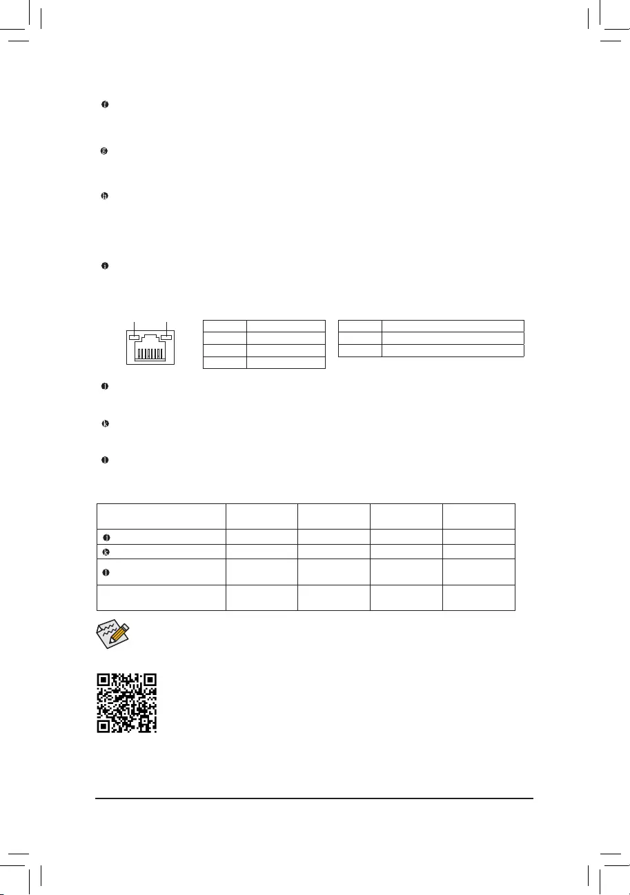
RJ-45 LAN Port
The Gigabit Ethernet LAN port provides Internet connection at up to 1 Gbps data rate. The following
describes the states of the LAN port LEDs.
LineIn/RearSpeakerOut(Blue)
The line in jack. Use this audio jack for line in devices such as an optical drive, walkman, etc.
LineOut/FrontSpeakerOut(Green)
The line out jack. Use this audio jack for a headphone or 2-channel speaker.
MicIn/Center/SubwooferSpeakerOut(Pink)
The Mic in jack.
•The integrated HD (High Denition) audio provides jack retasking capability that allows the
user to change the function for each jack through the audio driver.
•To congure 7.1-channel audio, you need to open the audio software and select Device
advanced settings > Playback Device to change the default setting rst.
Audio Jack Congurations:
Jack Headphone/
2-channel 4-channel 5.1-channel 7.1-channel
Line In/Rear Speaker Out a a a
Line Out/Front Speaker Out a a a a
Mic In/Center/Subwoofer
Speaker Out a a
Front Panel Line Out/Side
Speaker Out a
Activity LED
Connection/
Speed LED
LAN Port
State Description
Orange 1 Gbps data rate
Green 100 Mbps data rate
Off 10 Mbps data rate
State Description
Blinking Data transmission or receiving is occurring
Off No data transmission or receiving is occurring
— 11 —
1-7 Internal Connectors
Read the following guidelines before connecting external devices:
•First make sure your devices are compliant with the connectors you wish to connect.
•Before installing the devices, be sure to turn off the devices and your computer. Unplug the power
cord from the power outlet to prevent damage to the devices.
•After installing the device and before turning on the computer, make sure the device cable has
been securely attached to the connector on the motherboard.
1) ATX_12V
2) ATX
3) CPU_FAN
4) SYS_FAN1/2
5) D_LED1
6) LED_C
7) SATA3 0/1/2/3
 M2A_CPU
9) F_PANEL
10) F_ AUDIO
11) F_U32
12) F_USB1/F_USB2
13) TPM
14) COM
15) SPEAKER
16) CI
17) CLR_CMOS
18) BAT
912
2
7
413610
1
14
5
4
3
7
1517 11
18
8
16
— 12 —
131
2412
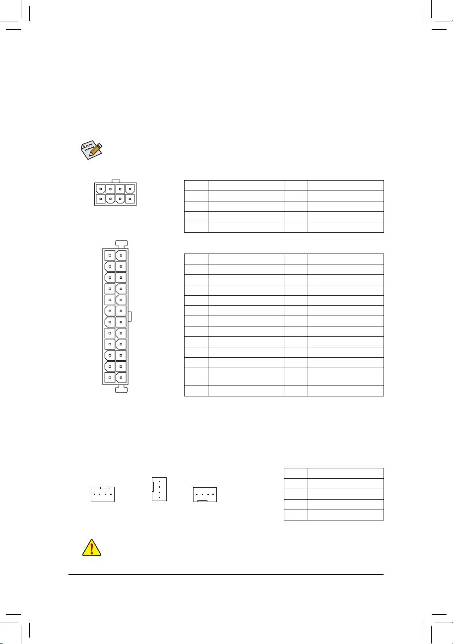
ATX
1/2) ATX_12V/ATX (2×4 12V Power Connector and 2×12 Main Power Connector)
With the use of the power connector, the power supply can supply enough stable power to all the components
on the motherboard. Before connecting the power connector, rst make sure the power supply is turned
off and all devices are properly installed. The power connector possesses a foolproof design. Connect the
power supply cable to the power connector in the correct orientation.
The 12V power connector mainly supplies power to the CPU. If the 12V power connector is not connected,
the computer will not start.
To meet expansion requirements, it is recommended that a power supply that can withstand high
power consumption be used (500W or greater). If a power supply is used that does not provide the
required power, the result can lead to an unstable or unbootable system.
ATX:
Pin No. Denition Pin No. Denition
1 3.3V 13 3.3V
2 3.3V 14 -12V
3 GND 15 GND
4 +5V 16 PS_ON (soft On/Off)
5 GND 17 GND
6 +5V 18 GND
7 GND 19 GND
8 Power Good 20 NC
9 5VSB (stand by +5V) 21 +5V
10 +12V 22 +5V
11 +12V (Only for 2×12-pin
ATX)
23 +5V (Only for 2×12-pin ATX)
12 3.3V (Only for 2×12-pin ATX) 24 GND (Only for 2×12-pin ATX)
ATX_12V:
Pin No. Denition Pin No. Denition
1 GND (Only for 2×4-pin 12V) 5 +12V (Only for 2×4-pin 12V)
2 GND (Only for 2×4-pin 12V) 6 +12V (Only for 2×4-pin 12V)
3 GND 7 +12V
4 GND 8 +12V
ATX_12V
41
85
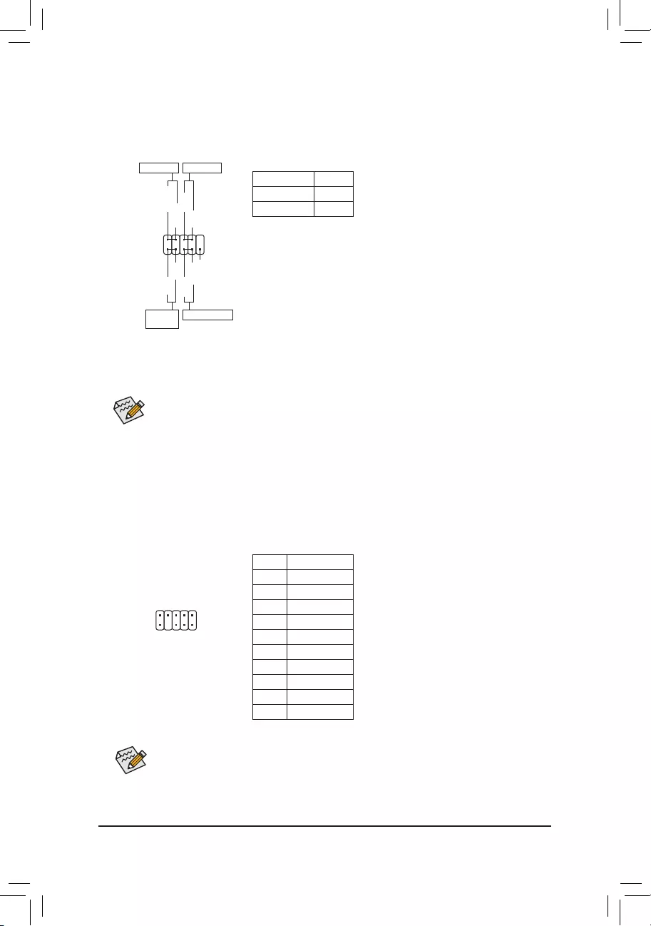
3/4)CPU_FAN/SYS_FAN1/2(FanHeaders)
All fan headers on this motherboard are 4-pin. Most fan headers possess a foolproof insertion design.
When connecting a fan cable, be sure to connect it in the correct orientation (the black connector wire is
the ground wire). The speed control function requires the use of a fan with fan speed control design. For
optimum heat dissipation, it is recommended that a system fan be installed inside the chassis.
•Be sure to connect fan cables to the fan headers to prevent your CPU and system from
overheating. Overheating may result in damage to the CPU or the system may hang.
•These fan headers are not conguration jumper blocks. Do not place a jumper cap on the headers.
CPU_FAN
1 1
SYS_FAN1 SYS_FAN2
1
Pin No. Denition
1 GND
2 Voltage Speed Control
3 Sense
4 PWM Speed Control
— 13 —
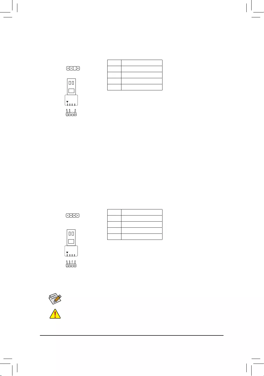
5) D_LED1 (Addressable LED Strip Header)
The header can be used to connect a standard 5050 addressable LED strip, with maximum power rating
of 5A (5V) and maximum number of 1000 LEDs.
Pin No. Denition
1 V (5V)
2 Data
3 No Pin
4 GND
1
Connect your addressable LED strip to the header. The power pin
(marked with a triangle on the plug) of the LED strip must be connected
to Pin 1 of the addressable LED strip header. Incorrect connection may
lead to the damage of the LED strip.
F_USB30 F_U
B_
F_ F_
_
B
BS_
B
SB_
B
_S
S_
_
B
_U
_
B
S
123
123
123
123
1
1
1
1
BSS
S
_S
SSU
1 2 3
S3 BSSS
U
__ 3
F_USB3F
S _
S _
S _
SF
B_
B_
F
_0
S
S
_0F
_F
_
_
__B
U
S _S
_ SF_
B
USB0_B
B_
B_
F_USB3
F_USB303
_
_3U
S_
Before installing the devices, be sure to turn off the devices and your computer. Unplug the power
cord from the power outlet to prevent damage to the devices.
For how to turn on/off the lights of the LED strip please visit the «Unique Features» webpage of
GIGABYTE’s website.
6) LED_C(RGBLEDStripHeader)
The header can be used to connect a standard 5050 RGB LED strip (12V/G/R/B), with maximum power
rating of 2A (12V) and maximum length of 2m.
Pin No. Denition
1 12V
2 G
3 R
4 B
Connect your RGB LED strip to the header. The power pin (marked
with a triangle on the plug) of the LED strip must be connected to Pin
1 (12V) of this header. Incorrect connection may lead to the damage
of the LED strip.
1
Addressable LED
Strip
1
RGB LED Strip
1
12V
— 14 —
M2A_CPU (M.2 Socket 3 Connector)
The M.2 connector supports M.2 SATA SSDs or M.2 PCIe SSDs and support RAID conguration. Please note that
an M.2 PCIe SSD cannot be used to create a RAID set with a SATA hard drive. Refer to Chapter 3, «Conguring
a RAID Set,» for instructions on conguring a RAID array.
Follow the steps below to correctly install an M.2 SSD in the M.2 connector.
Step 1:
Use a screw driver to unfasten the screw and standoff from the motherboard. Locate the proper mounting
hole for the M.2 SSD to be installed and then screw the standoff rst.
Step 2:
Slide the M.2 SSD into the connector at an angle.
Step 3:
Press the M.2 SSD down and then secure it with the screw.
Select the proper hole for the M.2 SSD to be installed and refasten the screw and standoff.
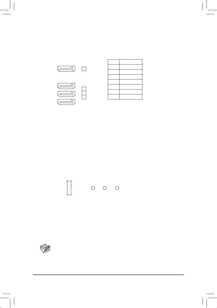
7) SATA30/1/2/3(SATA6Gb/sConnectors)
The SATA connectors conform to SATA 6Gb/s standard and are compatible with SATA 3Gb/s and SATA
1.5Gb/s standard. Each SATA connector supports a single SATA device. The SATA connectors support
RAID 0, RAID 1, and RAID 10. Refer to Chapter 3, «Conguring a RAID Set,» for instructions on conguring
a RAID array.
Pin No. Denition
1 GND
2 TXP
3 TXN
4 GND
5 RXN
6 RXP
7 GND
F_USB30 F_U
B_
F_ F_
_
B
BS_
B
SB_
B
_S
S_
_
B
_U
_
B
S
123
123
123
123
1
1
1
1
BSS
S
_S
SSU
1 2 3
S3 BSSS
U
__ 3
F_USB3F
S _
S _
S _
SF
B_
B_
F
_0
S
S
_0F
_F
_
_
__B
U
S _S
_ SF_
B
USB0_B
B_
B_
F_USB3
F_USB303
_
_3U
S_
80
6042
SATA3
2
1
0
71
71
71
71
3
— 15 —
9) F_PANEL(FrontPanelHeader)
Connect the power switch, reset switch, and system status indicator on the chassis to this header according
to the pin assignments below. Note the positive and negative pins before connecting the cables.
•PW (Power Switch):
Connects to the power switch on the chassis front panel. You may congure
the way to turn off your system using the power switch (refer to Chapter 2,
«BIOS Setup,» «Settings\Platform Power,» for more information).
•HD (Hard Drive Activity LED):
Connects to the hard drive activity LED on the chassis front panel. The
LED is on when the hard drive is reading or writing data.
•RES (Reset Switch):
Connects to the reset switch on the chassis front panel. Press the reset
switch to restart the computer if the computer freezes and fails to perform
a normal restart.
•NC:No connection.
•PLED (Power LED):
System Status LED
S0 On
S3/S4/S5 Off
Connects to the power status indicator on the
chassis front panel. The LED is on when the
system is operating. The LED is off when the
system is in S3/S4 sleep state or powered
off (S5).
The front panel design may differ by chassis. A front panel module mainly consists of power switch, reset switch,
power LED, hard drive activity LED and etc. When connecting your chassis front panel module to this header,
make sure the wire assignments and the pin assignments are matched correctly.
1
2
9
10
NC
PLED-
PW-
PLED+
PW+
HD-
RES+
HD+
RES-
Power LED Power Switch
Hard Drive
Activity LED
Reset Switch
10) F_AUDIO(FrontPanelAudioHeader)
The front panel audio header supports High Denition audio (HD). You may connect your chassis front
panel audio module to this header. Make sure the wire assignments of the module connector match the
pin assignments of the motherboard header. Incorrect connection between the module connector and the
motherboard header will make the device unable to work or even damage it.
Some chassis provide a front panel audio module that has separated connectors on each wire
instead of a single plug. For information about connecting the front panel audio module that has
different wire assignments, please contact the chassis manufacturer.
Pin No. Denition
1 MIC2_L
2 GND
3 MIC2_R
4 NC
5 LINE2_R
6 Sense
7 FAUDIO_JD
8 No Pin
9 LINE2_L
10 Sense
1
2
9
10
— 16 —
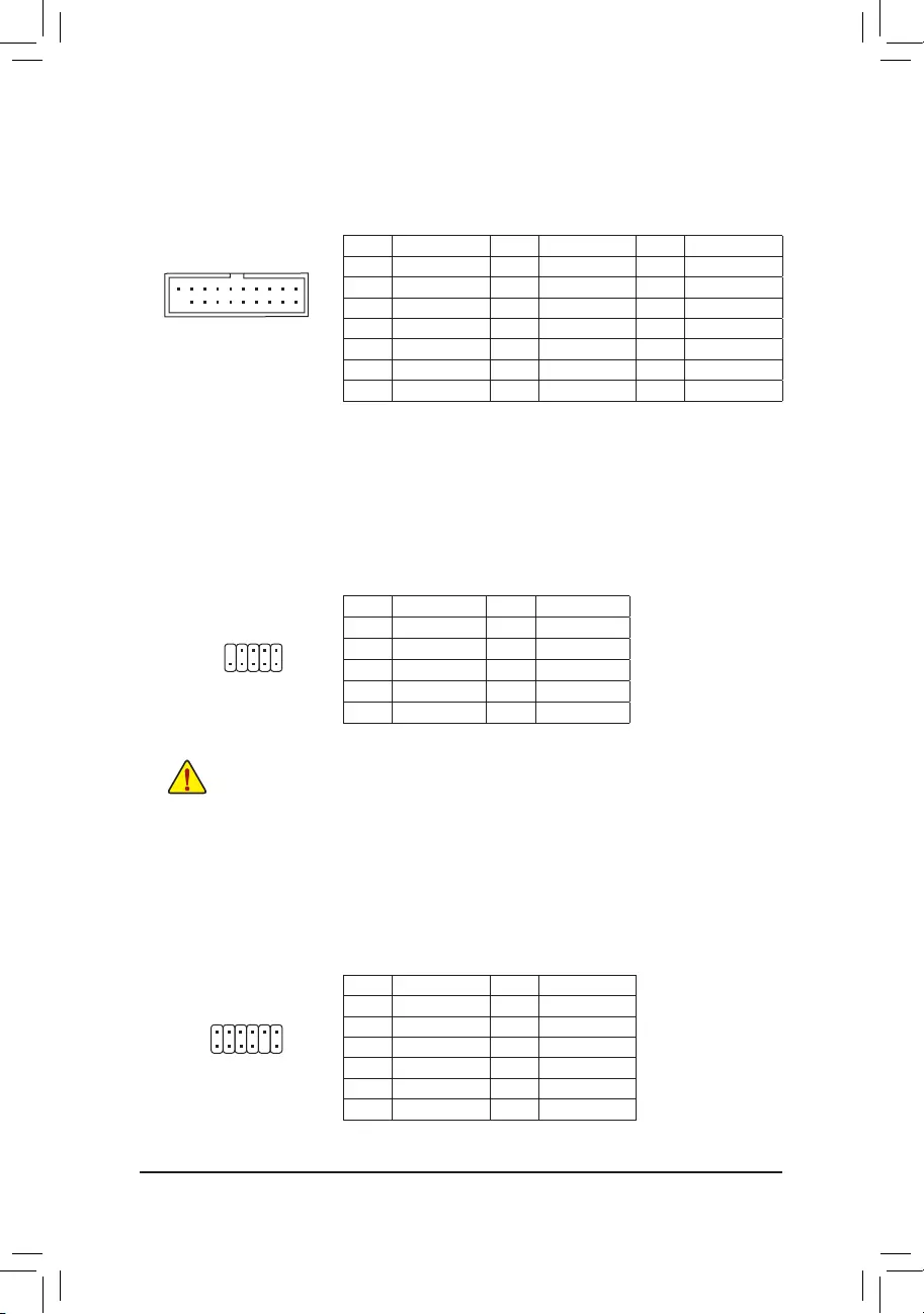
Pin No. Denition Pin No. Denition Pin No. Denition
1 VBUS 8 D1- 15 SSTX2-
2 SSRX1- 9 D1+ 16 GND
3 SSRX1+ 10 NC 17 SSRX2+
4 GND 11 D2+ 18 SSRX2-
5 SSTX1- 12 D2- 19 VBUS
6SSTX1+ 13 GND 20 No Pin
7 GND 14 SSTX2+
11) F_U32(USB3.2Gen1Header)
The header conforms to USB 3.2 Gen 1 and USB 2.0 specication and can provide two USB ports. For
purchasing the optional 3.5″ front panel that provides two USB 3.2 Gen 1 ports, please contact the local
dealer.
F_USB30 F_U
B_
F_ F_
_
B
BS_
B
SB_
B
_S
S_
_
B
_U
_
B
S
123
123
123
123
1
1
1
1
BSS
S
_S
SSU
1 2 3
S3 BSSS
U
__ 3
F_USB3F
S _
S _
S _
SF
B_
B_
F
_0
S
S
_0F
_F
_
_
__B
U
S _S
_ SF_
B
USB0_B
B_
B_
F_USB3
F_USB303
_
_3U
S_
11
1 10
20
13) TPM (Trusted Platform Module Header)
You may connect a TPM (Trusted Platform Module) to this header.
Pin No. Denition Pin No. Denition
1LAD0 7LAD3
2VCC3 8GND
3LAD1 9LFRAME
4No Pin 10 NC
5LAD2 11 SERIRQ
6LCLK 12 LRESET
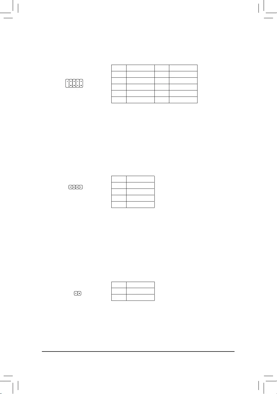
12) F_USB1/F_USB2(USB2.0/1.1Headers)
The headers conform to USB 2.0/1.1 specication. Each USB header can provide two USB ports via an
optional USB bracket. For purchasing the optional USB bracket, please contact the local dealer.
Pin No. Denition Pin No. Denition
1 Power (5V) 6 USB DY+
2 Power (5V) 7 GND
3 USB DX- 8 GND
4 USB DY— 9 No Pin
5 USB DX+ 10 NC
•Do not plug the IEEE 1394 bracket (2×5-pin) cable into the USB 2.0/1.1 header.
•Prior to installing the USB bracket, be sure to turn off your computer and unplug the power cord
from the power outlet to prevent damage to the USB bracket.
10
9
2
1
F_USB30 F_U
B_
F_ F_
_
B
BS_
B
SB_
B
_S
S_
_
B
_U
_
B
S
123
123
123
123
1
1
1
1
BSS
S
_S
SSU
1 2 3
S3 BSSS
U
__ 3
F_USB3F
S _
S _
S _
SF
B_
B_
F
_0
S
S
_0F
_F
_
_
__B
U
S _S
_ SF_
B
USB0_B
B_
B_
F_USB3
F_USB303
_
_3U
S_
12
11
2
1
— 17 —
14) COM(SerialPortHeader)
The COM header can provide one serial port via an optional COM port cable. For purchasing the optional
COM port cable, please contact the local dealer.
Pin No. Denition Pin No. Denition
1 NDCD- 6 NDSR-
2 NSIN 7 NRTS-
3 NSOUT 8 NCTS-
4 NDTR- 9 NRI-
5 GND 10 No Pin
10
9
2
1
15) SPEAKER (Speaker Header)
Connects to the speaker on the chassis front panel. The system reports system startup status by issuing
a beep code. One single short beep will be heard if no problem is detected at system startup.
Pin No. Denition
1 VCC
2 NC
3 NC
4 SPK-
1
16) CI (Chassis Intrusion Header)
This motherboard provides a chassis detection feature that detects if the chassis cover has been removed.
This function requires a chassis with chassis intrusion detection design.
1
Pin No. Denition
1 Signal
2 GND
— 18 —
17) CLR_CMOS(ClearCMOSJumper)
Use this jumper to clear the BIOS conguration and reset the CMOS values to factory defaults. To clear
the CMOS values, use a metal object like a screwdriver to touch the two pins for a few seconds.
•Always turn off your computer before clearing the CMOS values.
•After system restart, go to BIOS Setup to load factory defaults (select Load Optimized Defaults) or
manually congure the BIOS settings (refer to Chapter 2, «BIOS Setup,» for BIOS congurations).
Open: Normal
Short: Clear CMOS Values
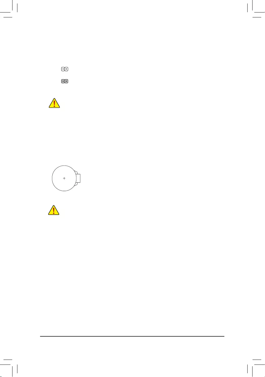
18) BAT (Battery)
The battery provides power to keep the values (such as BIOS congurations, date, and time information)
in the CMOS when the computer is turned off. Replace the battery when the battery voltage drops to a low
level, or the CMOS values may not be accurate or may be lost.
You may clear the CMOS values by removing the battery:
1. Turn off your computer and unplug the power cord.
2. Gently remove the battery from the battery holder and wait for one minute. (Or use a
metal object like a screwdriver to touch the positive and negative terminals of the battery
holder, making them short for 5 seconds.)
3. Replace the battery.
4. Plug in the power cord and restart your computer.
•Always turn off your computer and unplug the power cord before replacing the battery.
•Replace the battery with an equivalent one. Damage to your devices may occur if the battery is
replaced with an incorrect model.
•Contact the place of purchase or local dealer if you are not able to replace the battery by yourself
or uncertain about the battery model.
•When installing the battery, note the orientation of the positive side (+) and the negative side (-)
of the battery (the positive side should face up).
•Used batteries must be handled in accordance with local environmental regulations.
— 19 —
BIOS (Basic Input and Output System) records hardware parameters of the system in the CMOS on the
motherboard. Its major functions include conducting the Power-On Self-Test (POST) during system startup,
saving system parameters and loading operating system, etc. BIOS includes a BIOS Setup program that allows
the user to modify basic system conguration settings or to activate certain system features.
When the power is turned off, the battery on the motherboard supplies the necessary power to the CMOS to
keep the conguration values in the CMOS.
To access the BIOS Setup program, press the <Delete> key during the POST when the power is turned on.
To upgrade the BIOS, use either the GIGABYTE Q-Flash or @BIOS utility.
•Q-Flash allows the user to quickly and easily upgrade or back up BIOS without entering the operating system.
•@BIOS is a Windows-based utility that searches and downloads the latest version of BIOS from the Internet
and updates the BIOS.
Chapter2 BIOSSetup
•Because BIOS ashing is potentially risky, if you do not encounter problems using the current version of BIOS,
it is recommended that you not ash the BIOS. To ash the BIOS, do it with caution. Inadequate BIOS ashing
may result in system malfunction.
•It is recommended that you not alter the default settings (unless you need to) to prevent system instability or other
unexpected results. Inadequately altering the settings may result in system’s failure to boot. If this occurs, try to
clear the CMOS values and reset the board to default values. (Refer to the «Load Optimized Defaults» section in
this chapter or introductions of the battery/clear CMOS jumper in Chapter 1 for how to clear the CMOS values.)
2-1 Startup Screen
The following startup Logo screen will appear when the computer boots.
•When the system is not stable as usual, select the LoadOptimizedDefaults item to set your system to its defaults.
•The BIOS Setup menus described in this chapter are for reference only and may differ by BIOS version.
There are two different BIOS modes as follows and you can use the <F2> key to switch between the two modes.
Easy Mode allows users to quickly view their current system information or to make adjustments for optimum
performance. In Easy Mode, you can use your mouse to move through conguration items. The Advanced Mode
provides detailed BIOS settings. You can press the arrow keys on your keyboard to move among the items
and press <Enter> to accept or enter a sub-menu. Or you can use your mouse to select the item you want.
Function Keys
— 20 —
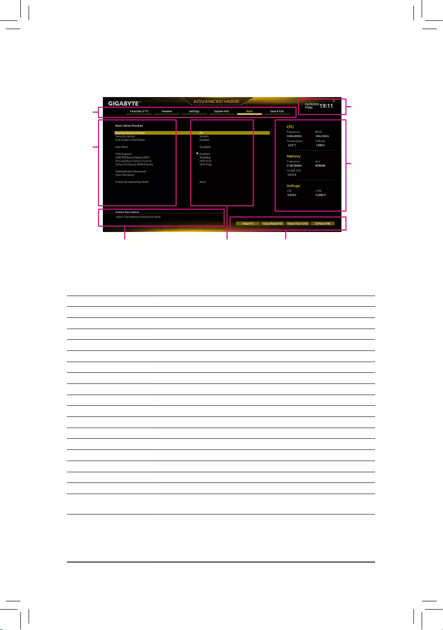
2-2 The Main Menu
AdvancedModeFunctionKeys
<f><g> Move the selection bar to select a setup menu
<h><i>Move the selection bar to select an conguration item on a menu
<Enter>/Double Click Execute command or enter a menu
<+>/<Page Up> Increase the numeric value or make changes
<—>/<Page Down> Decrease the numeric value or make changes
<F1> Show descriptions of the function keys
<F2> Switch to Easy Mode
<F3> Save the current BIOS settings to a prole
<F4> Load the BIOS settings from a prole created before
<F5> Restore the previous BIOS settings for the current submenus
<F6> Display the Smart Fan 5 screen
<F7> Load the Optimized BIOS default settings for the current submenus
<F8> Access the Q-Flash utility
<F10> Save all the changes and exit the BIOS Setup program
<F11> Switch to the Favorites submenu
<F12> Capture the current screen as an image and save it to your USB drive
<Insert> Add or remove a favorite option
<Ctrl>+<S> Display information on the installed memory
<Esc> Main Menu: Exit the BIOS Setup program
Submenus: Exit current submenu
Hardware Infor-
mation
Conguration Items Current Settings
Setup Menus
Congura—
tion Items
System Time
Quick Access Bar allows you to quickly move to
the General Help, Easy Mode, Smart Fan 5, or
Q-Flash screen.
— 21 —
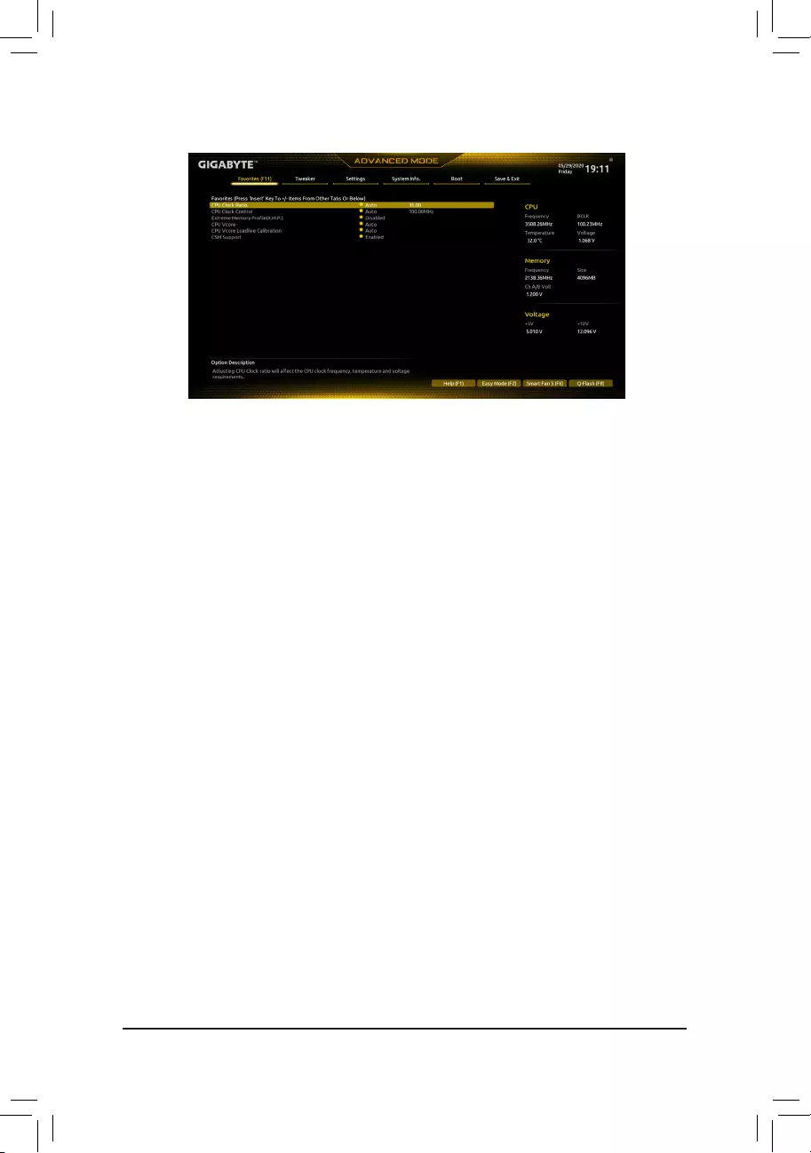
2-3 Favorites(F11)
Set your frequently used options as your favorites and use the <F11> key to quickly switch to the page where
all of your favorite options are located. To add or remove a favorite option, go to its original page and press
<Insert> on the option. The option is marked with a star sign if set as a «favorite.»
— 22 —
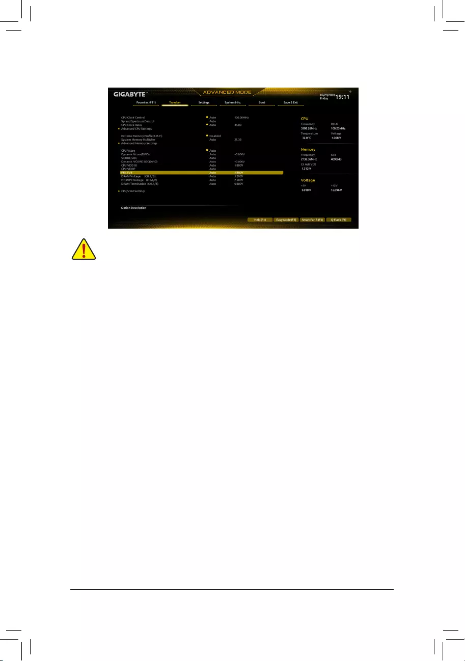
2-4 Tweaker
Whether the system will work stably with the overclock/overvoltage settings you made is dependent on your overall
system congurations. Incorrectly doing overclock/overvoltage may result in damage to CPU, chipset, or memory
and reduce the useful life of these components. This page is for advanced users only and we recommend you not to
alter the default settings to prevent system instability or other unexpected results. (Inadequately altering the settings
may result in system’s failure to boot. If this occurs, clear the CMOS values and reset the board to default values.)
&CPU Clock Control
Allows you to manually set the CPU base clock in 1 MHz increments. (Default: Auto)
Important:It is highly recommended that the CPU frequency be set in accordance with the CPU
specications.
&Spread Spectrum Control
Enables or disables CPU/PCIe Spread Spectrum. (Default: Auto)
&CPU Ratio Mode (Note)
Allows you to set the core ratio for all CPU cores or individual cores. (Default: All cores)
&CCD0 CCX0/1 Ratio (Note)
Allows you to manually set the core ratio for the CPU CCX0, 1 cores. This item is congurable only when
CPU Ratio Mode is set to Per CCX. (Default: Auto)
&CPU Clock Ratio
Allows you to alter the clock ratio for the installed CPU. The adjustable range is dependent on the CPU
being installed.
Advanced CPU Settings
&Core Performance Boost (Note)
Allows you to determine whether to enable the Core Performance Boost (CPB) technology, a CPU
performance-boost technology. (Default: Auto)
&SVM Mode
Virtualization enhanced by Virtualization Technology will allow a platform to run multiple operating systems
and applications in independent partitions. With virtualization, one computer system can function as multiple
virtual systems. (Default: Disabled)
&AMDCool&Quietfunction
Enabled Lets the AMD Cool’n’Quiet driver dynamically adjust the CPU clock and VID to
reduce heat output from your computer and its power consumption. (Default)
Disabled Disables this function.
(Note) This item is present only when you install a CPU that supports this feature.
— 23 —

&PPC Adjustment (Note 1)
Allows you to x the PState of the CPU. (Default: PState 0)
&GlobalC-stateControl (Note 1)
Allows you to determine whether to let the CPU enter C states. When enabled, the CPU core frequency
will be reduced during system halt state to decrease power consumption. (Default: Auto)
&Power Supply Idle Control (Note 1)
Enables or disables Package C6 State.
Typical Current Idle Disables this function.
Low Current Idle Enables this function.
Auto Lets the BIOS automatically congure this setting. (Default)
&CCD Control (Note 1)
Sets the number of CCDs to be used. (Default: Auto)
&Downcore Control
Allows you to select the number of CPU cores to enable (the number of CPU cores may vary by CPU).
(Default: Auto)
&SMT Mode
Allows you to enable or disable the CPU Simultaneous Multi-Threading technology. (Default: Auto)
&CPPC (Note 1)
Enables or disables the CPPC feature. (Default: Auto)
&CPPC Preferred Cores (Note 1)
Enables or disables the CPPC Preferred Cores feature. (Default: Auto)
&ExtremeMemoryProle(X.M.P.)(Note 2)
Allows the BIOS to read the SPD data on XMP memory module(s) to enhance memory performance when
enabled.
Disabled Disables this function. (Default)
Prole1 Uses Prole 1 settings.
Prole2 (Note 2) Uses Prole 2 settings.
&XMPHighFrequencySupport (Note 2)
Allows you to select the compatibility level for high-frequency memory. This item is congurable only when
ExtremeMemoryProle(X.M.P.) is set to Prole1 or Prole2. (Default: Auto)
&System Memory Multiplier
Allows you to set the system memory multiplier. Auto sets memory multiplier according to memory SPD
data. (Default: Auto)
Advanced Memory Settings
Memory Subtimings
d Standard Timing Control, Advanced Timing Control, CAD Bus Setup Timing, CAD Bus
DriveStrength,DataBusConguration
These sections provide memory timing settings. Note: Your system may become unstable or fail to boot
after you make changes on the memory timings. If this occurs, please reset the board to default values by
loading optimized defaults or clearing the CMOS values.
SPD Info
Displays information on the installed memory.
(Note 1) This item is present only when you install a CPU that supports this feature.
(Note 2) This item is present only when you install a CPU and a memory module that support this feature.
— 24 —

&CPUVcore/DynamicVcore(DVID)/VCORESOC/DynamicVCORESOC(DVID)/CPU
VDD18/CPU VDDP/A_VDD18S5/DRAM Voltage (CH A/B)/DDRVPP Voltage (CH A/B)/
DRAM Termination (CH A/B)
These items allow you to adjust the CPU Vcore and memory voltages.
CPU/VRM Settings
This submenu allows you to congure Load-Line Calibration level.
— 25 —
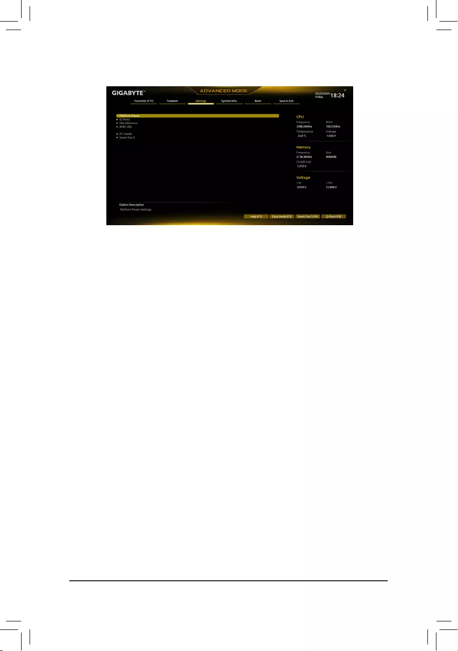
2-5 Settings
Platform Power
&AC BACK
Determines the state of the system after the return of power from an AC power loss.
Memory The system returns to its last known awake state upon the return of the AC power.
Always On The system is turned on upon the return of the AC power.
Always Off The system stays off upon the return of the AC power. (Default)
&PowerOnByKeyboard
Allows the system to be turned on by a PS/2 keyboard wake-up event.
Note: To use this function, you need an ATX power supply providing at least 1A on the +5VSB lead.
Disabled Disables this function. (Default)
Password Set a password with 1~5 characters to turn on the system.
Keyboard 98 Press POWER button on the Windows 98 keyboard to turn on the system.
Any key Press any key to turn on the system.
&PowerOnPassword
Set the password when PowerOnByKeyboard is set to Password.
Press <Enter> on this item and set a password with up to 5 characters and then press <Enter> to accept.
To turn on the system, enter the password and press <Enter>.
Note: To cancel the password, press <Enter> on this item. When prompted for the password, press <Enter>
again without entering the password to clear the password settings.
&PowerOnByMouse
Allows the system to be turned on by a PS/2 mouse wake-up event.
Note: To use this function, you need an ATX power supply providing at least 1A on the +5VSB lead.
Disabled Disables this function. (Default)
Move Move the mouse to turn on the system.
Double Click Double click on left button on the mouse to turn on the system.
&ErP
Determines whether to let the system consume least power in S5 (shutdown) state. (Default: Disabled)
Note: When this item is set to Enabled, the following functions will become unavailable: Resume by Alarm,
power on by mouse, power on by keyboard, and wake on LAN.
&Soft-OffbyPWR-BTTN
Congures the way to turn off the computer in MS-DOS mode using the power button.
Instant-Off Press the power button and then the system will be turned off instantly. (Default)
Delay 4 Sec. Press and hold the power button for 4 seconds to turn off the system. If the power
button is pressed for less than 4 seconds, the system will enter suspend mode.
— 26 —

&Power Loading
Enables or disables dummy load. When the power supply is at low load, a self-protection will activate causing
it to shutdown or fail. If this occurs, please set to Enabled. Auto lets the BIOS automatically congure this
setting. (Default: Auto)
&Resume by Alarm
Determines whether to power on the system at a desired time. (Default: Disabled)
If enabled, set the date and time as following:
Wake up day: Turn on the system at a specic time on each day or on a specic day in a month.
Wake up hour/minute/second: Set the time at which the system will be powered on automatically.
Note: When using this function, avoid inadequate shutdown from the operating system or removal of the
AC power, or the settings may not be effective.
&Wake on LAN
Enables or disables the wake on LAN function. (Default: Enabled)
&High Precision Event Timer
Enables or disables High Precision Event Timer (HPET) in the operating system. (Default: Enabled)
&CEC 2019 Ready
Allows you to select whether to allow the system to adjust power consumption when it is in shutdown, idle,
or standby state in order to comply with the CEC (California Energy Commission) 2019 Standards. (Default:
Disabled)
IOPorts
&InitialDisplayOutput
Species the rst initiation of the monitor display from the installed PCI Express graphics card or the onboard
graphics.
IGD Video (Note) Sets the onboard graphics as the rst display.
PCIe 1 Slot Sets the graphics card on the PCIEX16 slot as the rst display. (Default)
&IntegratedGraphics(Note)
Enables or disables the onboard graphics function.
Auto The BIOS will automatically enable or disable the onboard graphics
depending on the graphics card being installed. (Default)
Forces Enables the onboard graphics.
Disabled Disables the onboard graphics.
&UMA Mode (Note)
Specify the UMA mode.
Auto Lets the BIOS automatically congure this setting. (Default)
UMA Specied Sets the UMA Frame Buffer Size.
UMA Auto Sets the display resolution.
UMA Game Optimized Adjusts the frame buffer size based on the total system memory size.
This item is congurable only when IntegratedGraphics is set toForces.
&UMAFrameBufferSize (Note)
Frame buffer size is the total amount of system memory allocated solely for the onboard graphics controller.
MS-DOS, for example, will use only this memory for display. Options are: Auto (default), 64M~2G.
This item is congurable only when UMA Mode is set to UMASpecied.
&Display Resolution (Note)
Allows you to set the display resolution. Options are: Auto (default), 1920×1080 and below, 2560×1600,
3840×2160. This item is congurable only when UMA Mode is set to UMA Auto.
(Note) This item is present only when you install a CPU that supports this feature.
— 27 —

&HD Audio Controller
Enables or disables the onboard audio function. (Default: Enabled)
If you wish to install a 3rd party add-in audio card instead of using the onboard audio, set this item to
Disabled.
&PCIEX16 Bifurcation
Allows you to determine how the bandwidth of the PCIEX16 slot is divided. Options: Auto, PCIE 2×8,
PCIE 1×8/2×4, PCIE 2×4/1×8 (Note), PCIE 2×4/1×8, PCIE 4×4 (Note). (Default: Auto)
&Above4GDecoding
Enables or disables 64-bit capable devices to be decoded in above 4 GB address space (only if your system
supports 64-bit PCI decoding). Set to Enabled if more than one advanced graphics card are installed and
their drivers are not able to be launched when entering the operating system (because of the limited 4 GB
memory address space). (Default: Disabled)
&OnboardLANController
Enables or disables the onboard LAN function. (Default: Enabled)
If you wish to install a 3rd party add-in network card instead of using the onboard LAN, set this item to
Disabled.
`SuperIOConguration
&Serial Port 1
Enables or disables the onboard serial port. (Default: Enabled)
USBConguration
&Legacy USB Support
Allows USB keyboard/mouse to be used in MS-DOS. (Default: Enabled)
&XHCI Hand-off
Determines whether to enable XHCI Hand-off feature for an operating system without XHCI Hand-off
support. (Default: Enabled)
&USB Mass Storage Driver Support
Enables or disables support for USB storage devices. (Default: Enabled)
&Port 60/64 Emulation
Enables or disables emulation of I/O ports 64h and 60h. This should be enabled for full legacy support
for USB keyboards/mice in MS-DOS or in operating system that does not natively support USB devices.
(Default: Disabled)
&Mass Storage Devices
Displays a list of connected USB mass storage devices. This item appears only when a USB storage device
is installed.
NVMeConguration
Displays information on your M.2 NVME PCIe SSD if installed.
SATAConguration
&SATA Mode
Enables or disables RAID for the SATA controllers integrated in the Chipset or congures the SATA controllers
to AHCI mode.
RAID Enables RAID for the SATA controller.
AHCI Congures the SATA controllers to AHCI mode. Advanced Host Controller Interface
(AHCI) is an interface specication that allows the storage driver to enable advanced
Serial ATA features such as Native Command Queuing and hot plug. (Default)
(Note) This item is present only when you install a CPU that supports this feature.
— 28 —

&NVMe RAID mode
Allows you to determine whether to use your M.2 NVMe PCIe SSDs to congure RAID. (Default: Disabled)
&Chipset SATA Port Enable
Enables or disables the integrated SATA controllers. (Default: Enabled)
&Chipset SATA Port 0/1/2/3
Displays the information of the connected SATA device(s).
NetworkStackConguration
&Network Stack
Disables or enables booting from the network to install a GPT format OS, such as installing the OS from
the Windows Deployment Services server. (Default: Disabled)
&IPv4 PXE Support
Enables or disables IPv4 PXE Support. This item is congurable only when Network Stack is enabled.
&IPv4 HTTP Support
Enables or disables HTTP boot support for IPv4. This item is congurable only when Network Stack is
enabled.
&IPv6 PXE Support
Enables or disables IPv6 PXE Support. This item is congurable only when Network Stack is enabled.
&IPv6 HTTP Support
Enables or disables HTTP boot support for IPv6. This item is congurable only when Network Stack is
enabled.
&PXE boot wait time
Allows you to congure how long to wait before you can press <Esc> to abort the PXE boot. This item is
congurable only when Network Stack is enabled. (Default: 0)
&Media detect count
Allows you to set the number of times to check the presence of media. This item is congurable only when
Network Stack is enabled. (Default: 1)
RealtekPCIeGBEFamilyController
This sub-menu provides information on LAN conguration and related conguration options.
Miscellaneous
&LEDsinSystemPowerOnState
Allows you to enable or disable motherboard LED lighting when the system is on.
Off Disables the selected lighting mode when the system is on.
On Enables the selected lighting mode when the system is on. (Default)
&LEDsinSleep,Hibernation,andSoftOffStates
Allows you to set the lighting mode of the motherboard LEDs in system S3/S4/S5 state.
This item is congurable when LEDsinSystemPowerOnState is set to On.
Off Disables the selected lighting mode when the system enters S3/S4/S5 state. (Default)
On Enables the selected lighting mode when the system enters S3/S4/S5 state.
&PCIeSlotConguration
Allows you to set the operation mode of the PCI Express slots to Gen 1, Gen 2 or Gen 3. Actual operation
mode is subject to the hardware specication of each slot. Auto lets the BIOS automatically congure this
setting. (Default: Auto)
— 29 —

&3DMark01 Enhancement
Allows you to determine whether to enhance some legacy benchmark performance. (Default: Disabled)
&IOMMU
Enables or disables AMD IOMMU support. (Default: Auto)
&AMD CPU fTPM
Enables or disables the TPM 2.0 function integrated in the AMD CPU. (Default: Disabled)
Trusted Computing
Enables or disables Trusted Platform Module (TPM).
AMD CBS
This sub-menu provides AMD CBS-related conguration options.
PC Health
&ResetCaseOpenStatus
Disabled Keeps or clears the record of previous chassis intrusion status. (Default)
Enabled Clears the record of previous chassis intrusion status and the CaseOpen eld will
show «No» at next boot.
&CaseOpen
Displays the detection status of the chassis intrusion detection device attached to the motherboard CI
header. If the system chassis cover is removed, this eld will show «Yes», otherwise it will show «No». To
clear the chassis intrusion status record, set ResetCaseOpenStatus to Enabled, save the settings to
the CMOS, and then restart your system.
&CPUVcore/CPUVDDP/DRAMChannelA/BVoltage/+3.3V/+5V/+12V/VCORESOC
Displays the current system voltages.
SmartFan5
&Monitor
Allows you to select a target to monitor and to make further adjustment. (Default: CPU FAN)
&FanSpeedControl
Allows you to determine whether to enable the fan speed control function and adjust the fan speed.
Normal Allows the fan to run at different speeds according to the temperature. You can adjust
the fan speed with System Information Viewer based on your system requirements.
(Default)
Silent Allows the fan to run at slow speeds.
Manual Allows you to control the fan speed in the curve graph.
Full Speed Allows the fan to run at full speeds.
&FanControlUseTemperatureInput
Allows you to select the reference temperature for fan speed control.
&Temperature Interval
Allows you to select the temperature interval for fan speed change.
&FanControlmode
Auto Lets the BIOS automatically detect the type of fan installed and sets the optimal control
mode. (Default)
Voltage Voltage mode is recommended for a 3-pin fan.
PWM PWM mode is recommended for a 4-pin fan.
&FanStop
Enables or disables the fan stop function. You can set the temperature limit using the temperature curve.
The fan stops operation when the temperature is lower than the limit. (Default: Disabled)
— 30 —

&Temperature
Displays the current temperature of the selected target area.
&FanSpeed
Displays current fan speeds.
&Temperature Warning Control
Sets the warning threshold for temperature. When temperature exceeds the threshold, BIOS will emit
warning sound. Options are: Disabled (default), 60oC/140oF, 70oC/158oF, 80oC/176oF, 90oC/194oF.
&FanFailWarning
Allows the system to emit warning sound if the fan is not connected or fails. Check the fan condition or fan
connection when this occurs. (Default: Disabled)
— 31 —
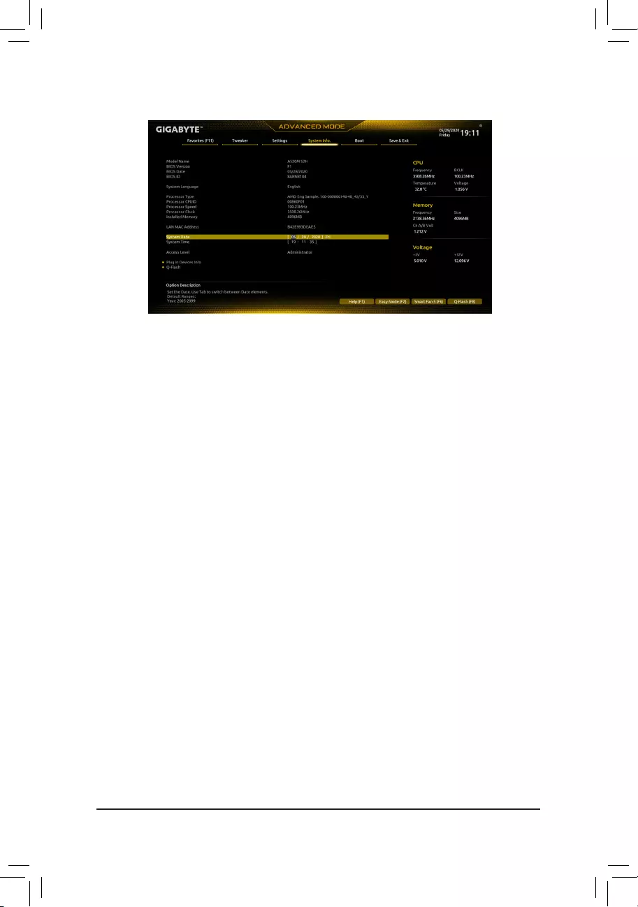
2-6 System Info.
This section provides information on your motherboard model and BIOS version. You can also select the default
language used by the BIOS and manually set the system time.
&System Language
Selects the default language used by the BIOS.
&System Date
Sets the system date. The date format is week (read-only), month, date, and year. Use <Enter> to switch
between the Month, Date, and Year elds and use the <Page Up> or <Page Down> key to set the desired
value.
&System Time
Sets the system time. The time format is hour, minute, and second. For example, 1 p.m. is 13:00:00. Use
<Enter> to switch between the Hour, Minute, and Second elds and use the <Page Up> or <Page Down>
key to set the desired value.
&Access Level
Displays the current access level depending on the type of password protection used. (If no password is
set, the default will display as Administrator.) The Administrator level allows you to make changes to all
BIOS settings; the User level only allows you to make changes to certain BIOS settings but not all.
Plug in Devices Info
Displays information on your SATA, PCI Express, and M.2 devices if installed.
Q-Flash
Allows you to access the Q-Flash utility to update the BIOS or back up the current BIOS conguration.
— 32 —
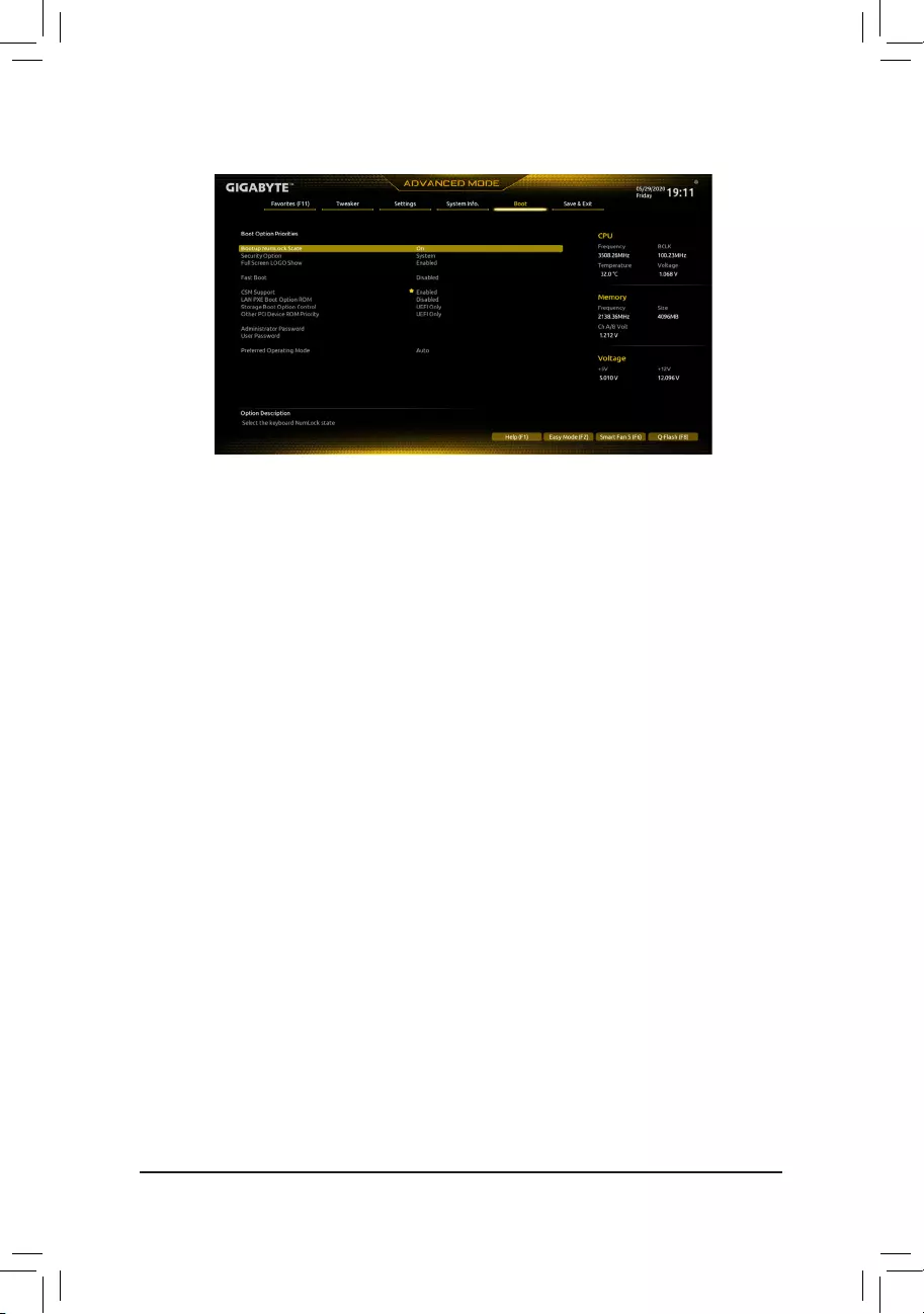
2-7 Boot
&BootOptionPriorities
Species the overall boot order from the available devices. Removable storage devices that support GPT
format will be prexed with «UEFI:» string on the boot device list. To boot from an operating system that
supports GPT partitioning, select the device prexed with «UEFI:» string.
Or if you want to install an operating system that supports GPT partitioning such as Windows 10 64-bit,
select the optical drive that contains the Windows 10 64-bit installation disc and is prexed with «UEFI:»
string.
&Bootup NumLock State
Enables or disables Numlock feature on the numeric keypad of the keyboard after the POST. (Default: On)
&SecurityOption
Species whether a password is required every time the system boots, or only when you enter BIOS Setup.
After conguring this item, set the password(s) under the Administrator Password/User Password item.
Setup A password is only required for entering the BIOS Setup program.
System A password is required for booting the system and for entering the BIOS Setup program.
(Default)
&FullScreenLOGOShow
Allows you to determine whether to display the GIGABYTE Logo at system startup. Disabled skips the
GIGABYTE Logo when the system starts up. (Default: Enabled)
&FastBoot
Enables or disables Fast Boot to shorten the OS boot process. UltraFast provides the fastest bootup
speed. (Default: Disabled)
&SATA Support
Last Boot SATA Devices Only Except for the previous boot drive, all SATA devices are disabled
before the OS boot process completes. (Default)
All SATA Devices All SATA devices are functional in the operating system and during the POST.
This item is congurable only when FastBoot is set to Enabled or UltraFast.
&NVMe Support
Allows you to enable or disable NVMe device(s). (Default: Enabled)
This item is congurable only when FastBoot is set to Enabled or UltraFast.
— 33 —

&VGASupport
Allows you to select which type of operating system to boot.
Auto Enables legacy option ROM only.
EFI Driver Enables EFI option ROM. (Default)
This item is congurable only when FastBoot is set to Enabled or UltraFast.
&USB Support
Disabled All USB devices are disabled before the OS boot process completes.
Full Initial All USB devices are functional in the operating system and during the POST.
(Default)
Partial Initial Part of the USB devices are disabled before the OS boot process completes.
This item is congurable only when FastBoot is set to Enabled. This function is disabled when FastBoot
is set to UltraFast.
&PS2 Devices Support
Disabled All PS/2 devices are disabled before the OS boot process completes.
Enabled All PS/2 devices are functional in the operating system and during the POST.
(Default)
This item is congurable only when FastBootis set to Enabled. This function is disabled when FastBoot
is set to UltraFast.
&NetWork Stack Driver Support
Disabled Disables booting from the network. (Default)
Enabled Enables booting from the network.
This item is congurable only when FastBoot is set to Enabled or UltraFast.
&CSM Support
Enables or disables UEFI CSM (Compatibility Support Module) to support a legacy PC boot process.
Disabled Disables UEFI CSM and supports UEFI BIOS boot process only.
Enabled Enables UEFI CSM. (Default)
&LANPXEBootOptionROM
Allows you to select whether to enable the legacy option ROM for the LAN controller. (Default: Disabled)
This item is congurable only when CSM Support is set to Enabled.
&StorageBootOptionControl
Allows you to select whether to enable the UEFI or legacy option ROM for the storage device controller.
Disabled Disables option ROM.
UEFI Only Enables UEFI option ROM only. (Default)
Legacy Only Enables legacy option ROM only.
This item is congurable only when CSM Support is set to Enabled.
&OtherPCIDeviceROMPriority
Allows you to select whether to enable the UEFI or Legacy option ROM for the PCI device controller other
than the LAN, storage device, and graphics controllers.
Disabled Disables option ROM.
UEFI Only Enables UEFI option ROM only. (Default)
Legacy Only Enables legacy option ROM only.
This item is congurable only when CSM Support is set to Enabled.
&Administrator Password
Allows you to congure an administrator password. Press <Enter> on this item, type the password, and
then press <Enter>. You will be requested to conrm the password. Type the password again and press
<Enter>. You must enter the administrator password (or user password) at system startup and when entering
BIOS Setup. Differing from the user password, the administrator password allows you to make changes to
all BIOS settings.
— 34 —

&User Password
Allows you to congure a user password. Press <Enter> on this item, type the password, and then press
<Enter>. You will be requested to conrm the password. Type the password again and press <Enter>.
You must enter the administrator password (or user password) at system startup and when entering BIOS
Setup. However, the user password only allows you to make changes to certain BIOS settings but not all.
To cancel the password, press <Enter> on the password item and when requested for the password, enter
the correct one rst. When prompted for a new password, press <Enter> without entering any password.
Press <Enter> again when prompted to conrm.
NOTE: Before setting the User Password, be sure to set the Administrator Password rst.
Secure Boot
Allows you to enable or disable Secure Boot and congure related settings. This item is congurable only
when CSM Support is set to Disabled.
&PreferredOperatingMode
Allows you to select whether to enter Easy mode or Advanced mode after entering BIOS Setup. Auto
enters the BIOS mode where it was last time. (Default: Auto)
— 35 —
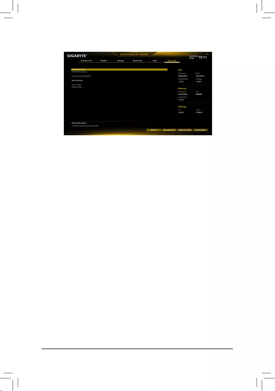
2-8 Save & Exit
&Save & Exit Setup
Press <Enter> on this item and select Yes. This saves the changes to the CMOS and exits the BIOS Setup
program. Select No or press <Esc> to return to the BIOS Setup Main Menu.
&Exit Without Saving
Press <Enter> on this item and select Yes. This exits the BIOS Setup without saving the changes made
in BIOS Setup to the CMOS. Select No or press <Esc> to return to the BIOS Setup Main Menu.
&LoadOptimizedDefaults
Press <Enter> on this item and select Yes to load the optimal BIOS default settings. The BIOS defaults
settings help the system to operate in optimum state. Always load the Optimized defaults after updating
the BIOS or after clearing the CMOS values.
&BootOverride
Allows you to select a device to boot immediately. Press <Enter> on the device you select and select Yes
to conrm. Your system will restart automatically and boot from that device.
&SaveProles
This function allows you to save the current BIOS settings to a prole. You can create up to 8 proles and
save as Setup Prole 1~ Setup Prole 8. Press <Enter> to complete. Or you can select SelectFilein
HDD/FDD/USB to save the prole to your storage device.
&LoadProles
If your system becomes unstable and you have loaded the BIOS default settings, you can use this function
to load the BIOS settings from a prole created before, without the hassles of reconguring the BIOS
settings. First select the prole you wish to load and then press <Enter> to complete. You can select Select
FileinHDD/FDD/USB to input the prole previously created from your storage device or load the prole
automatically created by the BIOS, such as reverting the BIOS settings to the last settings that worked
properly (last known good record).
— 36 —
Chapter 3 Appendix
3-1 ConguringaRAIDSet
(Note) An M.2 PCIe SSD cannot be used to set up a RAID set either with a SATA hard drive.
C.UEFIRAIDConguration
Steps:
1. In BIOS Setup, go to Boot and set CSM Support to Disabled. Save the changes and exit BIOS Setup.
2. After the system reboot, enter BIOS Setup again. Then enter the Settings\IO Ports\RAIDXpert2
CongurationUtility sub-menu.
3. On the RAIDXpert2CongurationUtility screen, press <Enter> on Array Management to enter the Create
Array screen. Then, select a RAID level. RAID levels supported include RAID 0, RAID 1, and RAID 10 (the
selections available depend on the number of the hard drives being installed). Next, press <Enter> on Select
Physical Disks to enter the Select Physical Disks screen.
4. On the Select Physical Disks screen, select the hard drives to be included in the RAID array and set them
to Enabled. Next, use the down arrow key to move to Apply Changes and press <Enter>. Then return
to the previous screen and set the SelectCacheTagSize, Read Cache Policy and Write Cache Policy.
5. Move to Create Array and press <Enter> to begin.
6. After completing, you’ll be brought back to the Array Management screen. Under Manage Array Properties
you can see the new RAID volume and information on RAID level, array name, array capacity, etc.
Beforeyoubegin,pleasepreparethefollowingitems:
•At least two SATA hard drives or SSDs. (Note) (To ensure optimal performance, it is recommended that you
use two hard drives with identical model and capacity). Windows setup disc.
•Motherboard driver disc.
•A USB thumb drive.
ConguringtheOnboardSATAController
A. Installing SATA hard drive(s) in your computer
Install the hard drives/SSDs in the SATA/M.2 connectors on the motherboard. Then connect the power connectors
from your power supply to the hard drives.
B.ConguringSATAcontrollermodeinBIOSSetup
Make sure to congure the SATA controller mode correctly in system BIOS Setup.
Steps:
Turn on your computer and press <Delete> to enter BIOS Setup during the POST (Power-On Self-Test). Under
Settings\IOPorts, set SATAConguration\SATAMode to RAID. Then save the settings and restart your
computer. (If you want to use NVMe PCIe SSDs to congure RAID, make sure to set NVMe RAID mode to
Enabled.)
The BIOS Setup menus described in this section may differ from the exact settings for your motherboard.
The actual BIOS Setup menu options you will see shall depend on the motherboard you have and the
BIOS version.
RAID Levels
RAID 0 RAID 1 RAID 10
Minimum Number of
Hard Drives ≥2 2 4
Array Capacity Number of hard drives *
Size of the smallest drive
Size of the smallest drive (Number of hard drives/2) *
Size of the smallest drive
Fault Tolerance No Yes Yes
— 37 —
Please visit GIGABYTE’s website for details on conguring a RAID array.
Install the RAID driver and operating system
With the correct BIOS settings, you are ready to install the operating system.
InstallingtheOperatingSystem
As some operating systems already include RAID driver, you do not need to install separate RAID driver during
the Windows installation process. After the operating system is installed, we recommend that you install all
required drivers from the motherboard driver disc using «Xpress Install» to ensure system performance and
compatibility. If the operating system to be installed requires that you provide additional RAID driver during the
OS installation process, please refer to the steps below:
1. Copy the Hw10 folder under the \BootDrv folder in the driver disc to your USB thumb drive.
2. Boot from the Windows setup disc and perform standard OS installation steps. When the screen requesting
you to load the driver appears, select Browse.
3. Insert the USB thumb drive and then browse to the location of the driver. The location of the drivers is as
follows:
\Hw10\RAID\x64
4. Select AMD-RAID Bottom Device rst and click Next to load the driver. Then select AMD-RAID Controller
and click Next to load the driver. Finally, continue the OS installation.
— 38 —
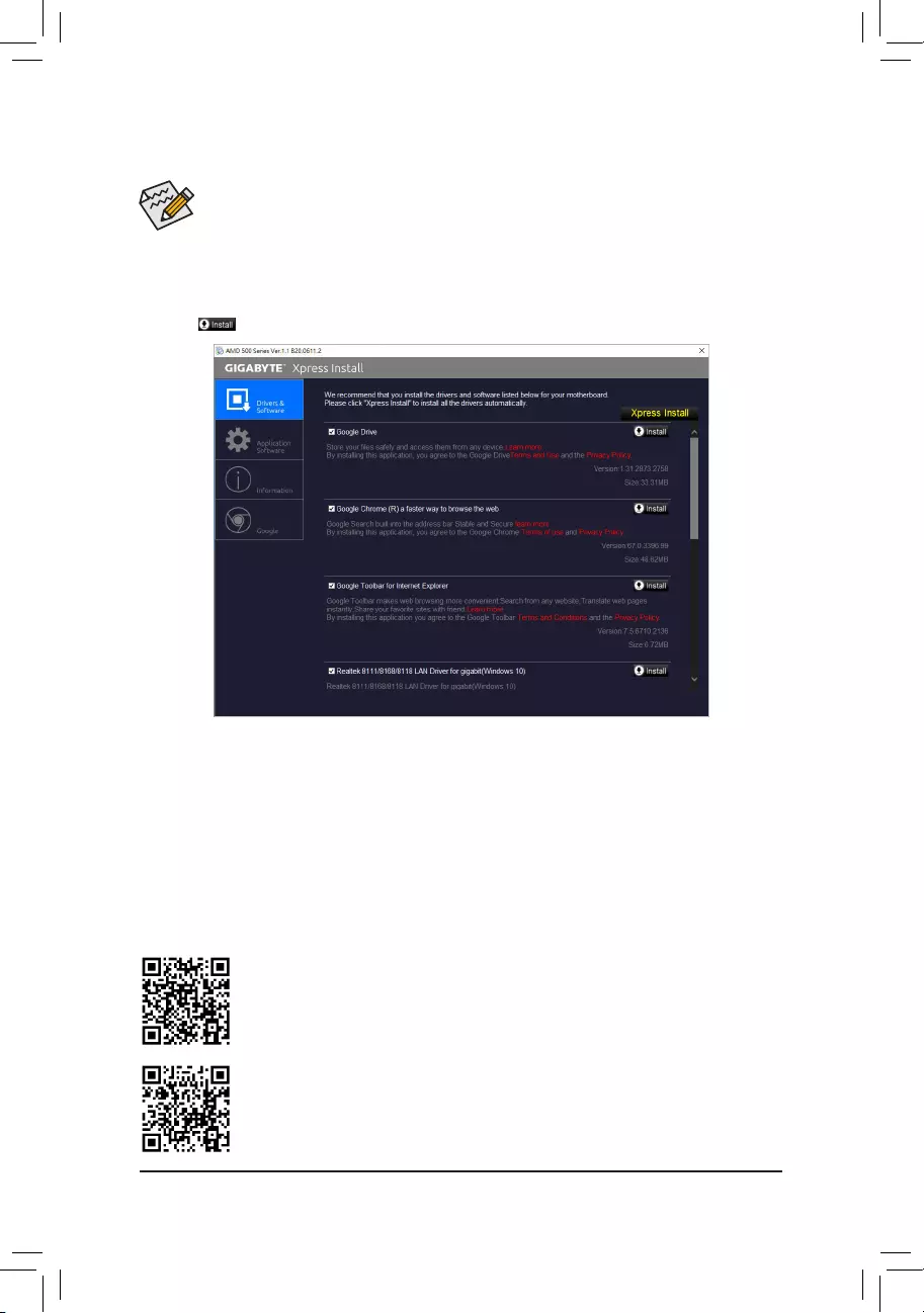
•Before installing the drivers, rst install the operating system.
•After installing the operating system, insert the motherboard driver disc into your optical drive. Click
on the message «Tap to choose what happens with this disc» on the top-right corner of the screen
and select «Run Run.exe.» (Or go to My Computer, double-click the optical drive and execute the
Run.exe program.)
«Xpress Install» will automatically scan your system and then list all of the drivers that are recommended to
install. You can click the Xpress Install button and «Xpress Install» will install all of the selected drivers. Or click
the arrow icon to individually install the drivers you need.
Please visit GIGABYTE’s website for more software information.
3-2 Drivers Installation
Please visit GIGABYTE’s website for more troubleshooting information.
— 39 —
Regulatory Notices
UnitedStatesofAmerica,FederalCommunicationsCommissionStatement
This equipment has been tested and found to comply with the limits for a
Class B digital device, pursuant to Part 15 of the FCC Rules. These limits
are designed to provide reasonable protection against harmful interference
in a residential installation. This equipment generates, uses and can radiate
radio frequency energy and, if not installed and used in accordance with
manufacturer’s instructions, may cause harmful interference to radio
communications. However, there is no guarantee that interference will
not occur in a particular installation. If this equipment does cause harmful
interference to radio or television reception, which can be determined by
turning the equipment off and on, the user is encouraged to try to correct
the interference by one or more of the following measures:
•Reorient or relocate the receiving antenna.
•Increase the separation between the equipment and receiver.
•Connect the equipment to an outlet on a circuit different from that to
which the receiver is connected.
•Consult the dealer or an experienced radio/TV technician for help.
Canadian Department of Communications Statement
This digital apparatus does not exceed the Class B limits for radio
noise emissions from digital apparatus set out in the Radio Interference
Regulations of the Canadian Department of Communications. This class
B digital apparatus complies with Canadian ICES-003.
Avis de conformité à la réglementation d’Industrie Canada
Cet appareil numérique de la classe B est conforme à la norme NMB-
003 du Canada.
European Union (EU) CE Declaration of Conformity
This device complies with the following directives: Electromagnetic
Compatibility Directive 2014/30/EU, Low-voltage Directive 2014/35/
EU, RoHS directive (recast) 2011/65/EU & the 2015/863 Statement.
This product has been tested and found to comply with all essential
requirements of the Directives.
European Union (EU) RoHS (recast) Directive 2011/65/EU & the
European Commission Delegated Directive (EU) 2015/863 Statement
GIGABYTE products have not intended to add and safe from hazardous
substances (Cd, Pb, Hg, Cr+6, PBDE, PBB, DEHP, BBP, DBP and DIBP).
The parts and components have been carefully selected to meet RoHS
requirement. Moreover, we at GIGABYTE are continuing our efforts to
develop products that do not use internationally banned toxic chemicals.
European Union (EU) Community Waste Electrical & Electronic
Equipment(WEEE)DirectiveStatement
GIGABYTE will fulll the national laws as interpreted from the 2012/19/
EU WEEE (Waste Electrical and Electronic Equipment) (recast) directive.
The WEEE Directive species the treatment, collection, recycling and
disposal of electric and electronic devices and their components. Under
the Directive, used equipment must be marked, collected separately, and
disposed of properly.
WEEE Symbol Statement
The symbol shown below is on the product or on its
packaging, which indicates that this product must not be
disposed of with other waste. Instead, the device should be
taken to the waste collection centers for activation of the
treatment, collection, recycling and disposal procedure.
For more information about where you can drop off your waste equipment
for recycling, please contact your local government ofce, your household
waste disposal service or where you purchased the product for details of
environmentally safe recycling.
End of Life Directives-Recycling
The symbol shown below is on the product or on its packaging,
which indicates that this product must not be disposed of with
other waste. Instead, the device should be taken to the waste
collection centers for activation of the treatment, collection,
recycling and disposal procedure.
Déclaration de Conformité aux Directives de l’Union européenne (UE)
Cet appareil portant la marque CE est conforme aux directives de l’UE
suivantes: directive Compatibilité Electromagnétique 2014/30/UE, directive
Basse Tension 2014/35/UE et directive RoHS II 2011/65/UE. La conformité
à ces directives est évaluée sur la base des normes européennes
harmonisées applicables.
European Union (EU) CE-Konformitätserklärung
Dieses Produkte mit CE-Kennzeichnung erfüllen folgenden EU-Richtlinien:
EMV-Richtlinie 2014/30/EU, Niederspannungsrichtlinie 2014/30/EU und
RoHS-Richtlinie 2011/65/EU erfüllt. Die Konformität mit diesen Richtlinien
wird unter Verwendung der entsprechenden Standards zurEuropäischen
Normierung beurteilt.
CE declaração de conformidade
Este produto com a marcação CE estão em conformidade com das
seguintes Diretivas UE: Diretiva Baixa Tensão 2014/35/EU; Diretiva CEM
2014/30/EU; Diretiva RSP 2011/65/UE. A conformidade com estas diretivas
é vericada utilizando as normas europeias harmonizadas.
CE Declaración de conformidad
Este producto que llevan la marca CE cumplen con las siguientes
Directivas de la Unión Europea: Directiva EMC (2014/30/EU), Directiva
de bajo voltaje (2014/35/EU), Directiva RoHS (recast) (2011/65/EU).
El cumplimiento de estas directivas se evalúa mediante las normas
europeas armonizadas.
DichiarazionediconformitàCE
Questo prodotto è conforme alle seguenti direttive: Direttiva sulla
compatibilità elettromagnetica 2014/30/UE, Direttiva sulla bassa tensione
2014/35/UE, Direttiva RoHS (rifusione) 2011/65/UE. Questo prodotto è
stato testato e trovato conforme a tutti i requisiti essenziali delle Direttive.
Supplier’s Declaration of Conformity
47 CFR § 2.1077 Compliance Information
Product Name: Motherboard
Trade Name: GIGABYTE
Model Number: A520M S2H
Responsible Party – U.S. Contact Information: G.B.T. Inc.
Address: 17358 Railroad street, City Of Industry, CA91748
Tel.: 1-626-854-9338
Internet contact information: https://www.gigabyte.com
FCC Compliance Statement:
This device complies with Part 15 of the FCC Rules, Subpart B, Unintentional Radiators.
Operation is subject to the following two conditions: (1) This device may not cause harmful interference, and (2) this
device must accept any interference received, including interference that may cause undesired operation.
— 40 —
Contact Us
GIGA—BYTETECHNOLOGYCO.,LTD.
Address: No.6, Baoqiang Rd., Xindian Dist., New Taipei City 231, Taiwan
TEL: +886-2-8912-4000, FAX: +886-2-8912-4005
Tech. and Non-Tech. Support (Sales/Marketing) : https://esupport.gigabyte.com
WEB address (English): https://www.gigabyte.com
WEB address (Chinese): https://www.gigabyte.com/tw
•GIGABYTEeSupport
To submit a technical or non-technical (Sales/Marketing) question, please link to:
https://esupport.gigabyte.com
— 41 —
Manual
View the manual for the Gigabyte A520M S2H here, for free. This user manual comes under the category motherboards and has been rated by 2 people with an average of a 8. This manual is available in the following languages: English. Do you have a question about the Gigabyte A520M S2H?
Ask your question here
Gigabyte A520M S2H specifications
Below you will find the product specifications and the manual specifications of the Gigabyte A520M S2H.
Processor manufacturer
AMD
Supported memory types
DDR4-SDRAM
Supported storage drive interfaces
M.2, PCI Express 3.0, SATA
Parallel processing technology support
—
General
| Brand | Gigabyte |
| Model | A520M S2H | A520M S2H |
| Product | motherboard |
| EAN | 0889523023594, 4719331809720, 889523023594 |
| Language | English |
| Filetype | User manual (PDF), Installation Guide (PDF) |
Processor
| Processor manufacturer | AMD |
| Processor socket | Socket AM4 |
| Compatible processor series | 3rd Generation AMD Ryzen™ 3 |
| Maximum internal memory supported by processor | 64 GB |
| Maximum number of SMP processors | 1 |
| Supported processor sockets | Socket AM4 |
Memory
| Supported memory types | DDR4-SDRAM |
| Number of memory slots | 2 |
| Memory slots type | DIMM |
| Supported memory clock speeds | 2133,2400,2667,2933,3200,3333,3600,4000,4400,4600,4866,5000 MHz |
| Maximum internal memory | 64 GB |
| Memory channels | Dual-channel |
Storage controllers
| Supported storage drive interfaces | M.2, PCI Express 3.0, SATA |
| RAID levels | 0, 1,10 |
| RAID support | Yes |
Graphics
| Parallel processing technology support | — |
| HDCP | Yes |
Internal I/O
| USB 2.0 connectors | 2 |
| USB 3.2 Gen 1 (3.1 Gen 1) connectors | 1 |
| USB 3.2 Gen 2 (3.1 Gen 2) connectors | 0 |
| Number of SATA II connectors | 0 |
| Number of SATA III connectors | 4 |
| ATX Power connector (24-pin) | Yes |
| CPU fan connector | Yes |
| Power fan connector | Yes |
| Number of chassis fan connectors | 2 |
| RGB LED pin header | Yes |
Rear panel I/O ports
| USB 2.0 ports quantity | 2 |
| USB 3.2 Gen 1 (3.1 Gen 1) Type-A ports quantity | 4 |
| USB 3.2 Gen 1 (3.1 Gen 1) Type-C ports quantity | 0 |
| USB 3.2 Gen 2 (3.1 Gen 2) Type-A ports quantity | 0 |
| USB 3.2 Gen 2 (3.1 Gen 2) Type-C ports quantity | 0 |
| Ethernet LAN (RJ-45) ports | 1 |
| PS/2 ports quantity | 1 |
| VGA (D-Sub) ports quantity | 1 |
| HDMI ports quantity | 1 |
| DVI-D ports quantity | 1 |
Network
Features
| Component for | PC |
| Motherboard form factor | micro ATX |
| Motherboard chipset family | AMD |
| Motherboard chipset | AMD A520 |
| Audio output channels | 7.1 channels |
BIOS
| BIOS type | UEFI AMI |
| BIOS memory size | 128 Mbit |
| ACPI version | 5.0 |
| Desktop Management Interface (DMI) version | 2.7 |
| System Management BIOS (SMBIOS) version | 2.7 |
| Clear CMOS jumper | Yes |
| Clear CMOS button | Yes |
Weight & dimensions
| Width | 244 mm |
| Depth | 205 mm |
| Height | 35 mm |
Logistics data
| Harmonized System (HS) code | 84733020 |
| Country of origin | China |
| Products per shipping (inner) case | 1 pc(s) |
Packaging data
| Package width | 265 mm |
| Package depth | 235 mm |
| Package height | 52 mm |
| Package weight | 740 g |
Technical details
| Warranty period | 3 year(s) |
Battery
| Battery weight | 3 g |
| Number of battery cells | 1 |
| Battery technology | Lithium-Manganese Dioxide (LiMnO2) |
| Lithium weight per battery | 0.07 g |
| Battery type | CR2032 |
Packaging content
show more
Frequently asked questions
Can’t find the answer to your question in the manual? You may find the answer to your question in the FAQs about the Gigabyte A520M S2H below.
What is the height of the Gigabyte A520M S2H?
The Gigabyte A520M S2H has a height of 35 mm.
What is the width of the Gigabyte A520M S2H?
The Gigabyte A520M S2H has a width of 244 mm.
What is the depth of the Gigabyte A520M S2H?
The Gigabyte A520M S2H has a depth of 205 mm.
Is the manual of the Gigabyte A520M S2H available in English?
Yes, the manual of the Gigabyte A520M S2H is available in English .
Is your question not listed? Ask your question here
- June 16, 2024
- Gigabyte
Table of Contents
- A520M S2H Motherboard
- Product Introduction
- Hardware Installation
- BIOS Setup
- Installing the Operating System and Drivers
- Appendix
- Regulatory Notices
- Contact Us
- Documents / Resources
- References
- Read User Manual Online (PDF format)
- Download This Manual (PDF format)
A520M S2H
User’s Manual
Rev. 1301
A520M S2H Motherboard
GIGABYTE will reduce paper use in order to fulfill the responsibilities of a
global citizen.
Also, to reduce the impacts on global warming, the packaging materials of this
product are recyclable and reusable. GIGABYTE works with you to protect the
environment.
For more product details, please visit GIGABYTE’s website.
Copyright
© 2023 GIGA-BYTE TECHNOLOGY CO., LTD. All rights reserved.
The trademarks mentioned in this manual are legally registered to their
respective owners.
Disclaimer
Information in this manual is protected by copyright laws and is the property
of GIGABYTE.
Changes to the specifications and features in this manual may be made by
GIGABYTE without prior notice. No part of this manual may be reproduced,
copied, translated, transmitted, or published in any form or by any means
without GIGABYTE’s prior written permission.
- For detailed product information, carefully read the User’s Manual.
- For quick set-up of the product, refer to the Quick Installation Guide on GIGABYTE’s website. https://download.gigabyte.com/FileList/Manual/mb_manual_installation-guide_103.pdf?m=sw
For product-related information, check on our website at:
https://www.gigabyte.com
Identifying Your Motherboard Revision
The revision number on your motherboard looks like this: “REV: X.X.” For
example, “REV: 1.0” means the revision of the motherboard is 1.0. Check your
motherboard revision before updating motherboard BIOS, drivers, or when
looking for technical information.
Example:
Product Introduction
1-1 Motherboard Layout
Hardware Installation
2-1 Installation Precautions
The motherboard contains numerous delicate electronic circuits and components
which can become damaged as a result of electrostatic discharge (ESD). Prior
to installation, carefully read the user’s manual and follow these procedures:
- Prior to installation, make sure the chassis is suitable for the motherboard.
- Prior to installation, do not remove or break motherboard S/N (Serial Number) sticker or warranty sticker provided by your dealer. These stickers are required for warranty validation.
- Always remove the AC power by unplugging the power cord from the power outlet before installing or removing the motherboard or other hardware components.
- When connecting hardware components to the internal connectors on the motherboard, make sure they are connected tightly and securely.
- When handling the motherboard, avoid touching any metal leads or connectors.
- It is best to wear an electrostatic discharge (ESD) wrist strap when handling electronic components such as a motherboard, CPU or memory. If you do not have an ESD wrist strap, keep your hands dry and first touch a metal object to eliminate static electricity.
- Prior to installing the motherboard, please have it on top of an antistatic pad or within an electrostatic shielding container.
- Before connecting or unplugging the power supply cable from the motherboard, make sure the power supply has been turned off.
- Before turning on the power, make sure the power supply voltage has been set according to the local voltage standard.
- Before using the product, please verify that all cables and power connectors of your hardware components are connected.
- To prevent damage to the motherboard, do not allow screws to come in contact with the motherboard circuit or its components.
- Make sure there are no leftover screws or metal components placed on the motherboard or within the computer casing.
- Do not place the computer system on an uneven surface.
- Do not place the computer system in a high-temperature or wet environment.
- Turning on the computer power during the installation process can lead to damage to system components as well as physical harm to the user.
- If you are uncertain about any installation steps or have a problem related to the use of the product, please consult a certified computer technician.
- If you use an adapter, extension power cable, or power strip, ensure to consult with its installation and/or grounding instructions.
2-2 Product Specifications
CPU| AMD Socket AM4, support for: AMD Ryzen ™ 5000 G-Series Processors/ AMD
Ryzen ™
5000 Series Processors/ AMD Ryzen ™
4000 G-Series Processors/ AMD Ryzen ™
3000 G-Series Processors/ AMD Ryzen ™ 3000 Series Processors
(Go to GIGABYTE’s website for the latest CPU support list.)
—|—
Chipset| AMD A520
Memory| 2 x DDR4 DIMM sockets supporting up to 64 GB (32 GB single DIMM
capacity) of system memory
Support for DDR4 3200/2933/2667/2400/2133 MT/s memory modules
Dual channel memory architecture
Support for ECC Un-buffered DIMM 1Rx8/2Rx8 memory modules
Support for non-ECC Un-buffered DIMM 1Rx8/2Rx8/1Rx16 memory modules
Support for Extreme Memory Profile (XMP) memory modules
(Go to GIGABYTE’s website for the latest supported memory speeds and memory
modules.)
Onboard Graphics| Integrated Graphics Processor with AMD Radeon ™ Graphics
support:
– 1 x D-Sub port, supporting a maximum resolution of 1920×1200@60 Hz
– 1 x DVI-D port, supporting a maximum resolution of 1920×1200@60 Hz
-
The DVI-D port does not support D-Sub connection by adapter.
– 1 x HDMI port, supporting a maximum resolution of 4096×2160@60 Hz -
Support for HDMI 2.1 version, HDCP 2.3, and HDR.
Support for up to 3 displays at the same time Maximum shared memory of 16 GB
Audio| Realtek ® audio CODEC High Definition Audio 2/4/5.1/7.1-channel
You can change the functionality of an audio jack using the audio software. To configure 7.1-channel audio, access the audio software for audio settings..
LAN| Realtek GbE LAN chip (1 Gbps/100 Mbps/10 Mbps)
Expansion Slots| CPU: – 1 x PCI Express x16 slot, supporting PCIe 3.0 and
running at
Chipset: – 2 x PCI Express x1 slots, supporting PCIe 3.0
Storage Interface| CPU: – 1 x M.2 connector (Socket 3, M key, type
2242/2260/2280 SATA and PCIe 3.0 x4/x2 SSD support)
Chipset: – 4 x SATA 6Gb/s connectors
– Support for RAID 0, RAID 1, and RAID 10
USB| CPU: – 4 x USB 3.2 Gen 1 ports on the back panel
Chipset: – 2 x USB 3.2 Gen 1 ports available through the internal USB header –
6 x USB 2.0/1.1 ports (2 ports on the back panel, 4 ports available through
the internal USB headers)
Internal Connectors| 1 x 24-pin ATX main power connector
1 x 8-pin ATX 12V power connector
1 x CPU fan header
2 x system fan headers
1 x addressable LED strip header
1 x RGB LED strip header
1 x M.2 Socket 3 connector
4 x SATA 6Gb/s connectors
1 x front panel header
1 x front panel audio header
1 x USB 3.2 Gen 1 header
2 x USB 2.0/1.1 headers
1 x Trusted Platform Module (TPM) header (2×6 pin, for the GC-TPM2.0_S module
only)
1 x serial port header
1 x speaker header
1 x chassis intrusion header
1 x Clear CMOS jumper
Back Panel Connectors| 1 x PS/2 keyboard/mouse port
1 x D-Sub port
1 x DVI-D port
1 x HDMI port
4 x USB 3.2 Gen 1 ports
2 x USB 2.0/1.1 ports
1 x RJ-45 port
1 x Q-Flash Plus button
3 x audio jacks
I/O Controller| iTE ® I/O Controller Chip
Hardware Monitor| Voltage detection
Temperature detection
Fan speed detection
Overheating warning
Fan fail warning
Fan speed control
Whether the fan speed control function is supported will depend on the fan you install.
BIOS| 1 x 128 Mbit flash
Use of licensed AMI UEFI BIOS
PnP 1.0a, DMI 2.7, WfM 2.0, SM BIOS 2.7, ACPI 5.0
Unique Features| Support for APP Center -
Available applications in APP Center may vary by motherboard model. Supported functions of each application may also vary depending on motherboard specifications.
– @BIOS
– EasyTune
– RGB Fusion
– Smart Backup
– System Information Viewer
Support for Q-Flash Plus
Support for Q-Flash
Bundled Software| Norton ®
Internet Security (OEM version)
LAN bandwidth management software
Operating System| Support for Windows 11 64-bit
Support for Windows 10 64-bit
Form Factor| Micro ATX Form Factor; 24.4cm x 20.5cm -
GIGABYTE reserves the right to make any changes to the product specifications and product-related information without prior notice.
2-3 Installing the CPU
Read the following guidelines before you begin to install the CPU:
- Make sure that the motherboard supports the CPU. (Go to GIGABYTE’s website for the latest CPU support list.)
- Always turn off the computer and unplug the power cord from the power outlet before installing the CPU to prevent hardware damage.
- Locate the pin one of the CPU. The CPU cannot be inserted if oriented incorrectly.
- Apply an even and thin layer of thermal grease on the surface of the CPU.
- Do not turn on the computer if the CPU cooler is not installed, otherwise overheating and damage of the CPU may occur.
- Set the CPU host frequency in accordance with the CPU specifications. It is not recommended that the system bus frequency be set beyond hardware specifications since it does not meet the standard requirements for the peripherals. If you wish to set the frequency beyond the standard specifications, please do so according to your hardware specifications including the CPU, graphics card, memory, hard drive, etc.
Installing the CPU
Completely lift up the CPU socket locking lever. Locate the pin one (denoted
by a small triangle) of the CPU socket and the CPU. Once the CPU is positioned
into its socket, place one finger down on the middle of the CPU, lowering the
locking lever and latching it into the fully locked position.
Do not force the CPU into the CPU socket before the CPU socket locking lever
is lifted up, or damage to the CPU and CPU socket may occur.
2-4 Installing the Memory
Read the following guidelines before you begin to install the memory:
- Make sure that the motherboard supports the memory. It is recommended that memory of the same capacity, brand, speed, and chips be used. (Go to GIGABYTE’s website for the latest supported memory speeds and memory modules.)
- Always turn off the computer and unplug the power cord from the power outlet before installing the memory to prevent hardware damage.
- Memory modules have a foolproof design. A memory module can be installed in only one direction.
If you are unable to insert the memory, switch the direction.
Dual Channel Memory Configuration
This motherboard provides two memory sockets and supports Dual Channel
Technology. After the memory is installed, the BIOS will automatically detect
the specifications and capacity of the memory. Enabling Dual Channel memory
mode will double the original memory bandwidth.
The two memory sockets are divided into two channels and each channel has one
memory socket as following:
Channel A: DDR4_A1
Channel B: DDR4_B1
Due to CPU limitations, read the following guidelines before installing the
memory in Dual Channel mode.
- Dual Channel mode cannot be enabled if only one memory module is installed.
- When enabling Dual Channel mode with two memory modules, it is recommended that memory of the same capacity, brand, speed, and chips be used.
2-5 Installing an Expansion Card
Read the following guidelines before you begin to install an expansion card:
- Make sure the motherboard supports the expansion card. Carefully read the manual that came with your expansion card.
- Always turn off the computer and unplug the power cord from the power outlet before installing an expansion card to prevent hardware damage.
2-6 Back Panel Connectors
a USB 2.0/1.1 Port
The USB port supports the USB 2.0/1.1 specification. Use this port for USB
devices.
b PS/2 Keyboard/Mouse Port
Use this port to connect a PS/2 mouse or keyboard.
c D-Sub Port
(Note 1)
The D-Sub port supports a 15-pin D-Sub connector and supports a maximum
resolution of 1920×1200@60 Hz (the actual resolutions supported depend on the
monitor being used). Connect a monitor that supports D-Sub connection to this
port.
d DVI-D Port
(Note 1)(Note 2)
The DVI-D port conforms to the DVI-D specification and supports a maximum
resolution of 1920×1200@60 Hz (the actual resolutions supported depend on the
monitor being used). Connect a monitor that supports DVI-D connection to this
port.
e HDMI Port (Note 1)
The HDMI port is HDCP 2.3 compliant and supports Dolby TrueHD and DTS HD
Master Audio formats. It also supports up to 192KHz/24bit 7.1-channel LPCM
audio output.
You can use this port to connect your HDMI-supported monitor. The maximum
supported resolution is 4096×2160@60 Hz, but the actual resolutions supported
are dependent on the monitor being used.
- To set up a triple-display configuration, you must install motherboard drivers in the operating system first.
- After installing the HDMI device, make sure to set the default sound playback device to HDMI. (The item name may differ depending on your operating system.)
Triple-Display Configurations for the Onboard Graphics:
Triple-display configurations are supported after you install motherboard
drivers in OS. Only single display is available during the BIOS Setup or POST
process.
- When removing the cable connected to a back panel connector, first remove the cable from your device and then remove it from the motherboard.
- When removing the cable, pull it straight out from the connector. Do not rock it side to side to prevent an electrical short inside the cable connector.
f USB 3.2 Gen 1 Port
The USB 3.2 Gen 1 port supports the USB 3.2 Gen 1 specification and is
compatible to the USB 2.0 specification. Use this port for USB devices.
g USB 3.2 Gen 1 Port (Q-Flash Plus Port)
The USB port supports the USB 3.2 Gen 1 specification. Use this port for USB
devices. Before using Q-Flash Plus
(Note 3) , make sure to insert the USB flash drive into this port first.
h Q-Flash Plus Button
(Note 3)
Q-Flash Plus allows you to update the BIOS when your system is off (S5
shutdown state). Save the latest BIOS on a USB thumb drive and plug it into
the Q-Flash Plus port, and then you can now flash the BIOS automatically by
simply pressing the Q-Flash Plus button. The QFLED will flash when the BIOS
matching and flashing activities start and will stop flashing when the main
BIOS flashing is complete.
RJ-45 LAN Port
The Gigabit Ethernet LAN port provides Internet connection at up to 1 Gbps
data rate. The following describes the states of the LAN port LEDs.
Speed LED:
| State | Description |
|---|---|
| Orange | 1 Gbps data rate |
| Green | 100 Mbps data rate |
| Off | 10 Mbps data rate |
Activity LED:
| State | Description |
|---|---|
| Blinking | Data transmission or receiving is occurring |
| Off | No data transmission or receiving is occurring |
j Line In/Rear Speaker Out (Blue)
The line in jack. Use this audio jack for line in devices such as an optical
drive, walkman, etc.
k Line Out/Front Speaker Out (Green)
The line out jack.
l Mic In/Center/Subwoofer Speaker Out (Pink)
The Mic in jack.
Audio Jack Configurations:
Jack| Headphone/ 2-channel| 4-channel| 5.1-channel|
7.1-channel
—|—|—|—|—
Line In/Rear Speaker Out| | | |
Line Out/Front Speaker Out| | | |
Mic In/Center/Subwoofer
Speaker Out| | | |
Front Panel Line Out/Side
Speaker Out| | | |
You can change the functionality of an audio jack using the audio software. To
configure 7.1-channel audio, access the audio software for audio settings.
Please visit GIGABYTE’s website for details on configuring the audio software.
https://www.gigabyte.com/WebPage/697/realtek897-audio.html
(Note 1) For AMD Ryzen ™ 5000 G-Series/4000 G-Series/3000 G-Series Processors
only.
(Note 2) The DVI-D port does not support D-Sub connection by adapter.
(Note 3) To enable the Q-Flash Plus function please visit the “Unique
Features” webpage of GIGABYTE’s website.
2-7 Internal Connectors
-
ATX_12V 10) F_ AUDIO - ATX| 11) F_U32
- CPU_FAN| 12) F_USB1/F_USB2
- SYS_FAN1/2| 13) TPM
- D_LED1| 14) COM
- LED_C| 15) SPEAKER
- SATA3 0/1/2/3| 16) CI
- M2A_CPU| 17) CLR_CMOS
- F_ PANEL| 18) BAT
Read the following guidelines before connecting external devices:
- First make sure your devices are compliant with the connectors you wish to connect.
- Before installing the devices, be sure to turn off the devices and your computer. Unplug the power cord from the power outlet to prevent damage to the devices.
- After installing the device and before turning on the computer, make sure the device cable has been securely attached to the connector on the motherboard.
1/2) ATX_12V/ATX (2×4 12V Power Connector and 2×12 Main Power Connector)
With the use of the power connector, the power supply can supply enough stable
power to all the components on the motherboard. Before connecting the power
connector, first make sure the power supply is turned off and all devices are
properly installed. The power connector possesses a foolproof design. Connect
the power supply cable to the power connector in the correct orientation.
The 12V power connector mainly supplies power to the CPU. If the 12V power
connector is not connected, the computer will not start.
To meet expansion requirements, it is recommended that a power supply that can
withstand high power consumption be used (500W or greater). If a power supply
is used that does not provide the required power, the result can lead to an
unstable or unbootable system.
ATX:
| Pin No. | Definition |
|---|---|
| 1 | 3.3V |
| 2 | 3.3V |
| 3 | GND |
| 4 | +5V |
| 5 | GND |
| 6 | +5V |
| 7 | GND |
| 8 | Power Good |
| 9 | 5VSB (stand by +5V) |
| 10 | +12V |
| 11 | 12V (Only for 2×12-pinATX) |
| 12 | 3.3V (Only for 2×12-pin ATX) |
| 13 | 3.3V |
| 14 | -12V |
| 15 | GND |
| 16 | PS_ON (soft On/Off) |
| 17 | GND |
| 18 | GND |
| 19 | GND |
| 20 | NC |
| 21 | +5V |
| 22 | +5V |
| 23 | +5V (Only for 2×12-pin ATX) |
| 24 | GND (Only for 2×12-pin ATX) |
3/4) CPU_FAN/SYS_FAN1/2 (Fan Headers)
All fan headers on this motherboard are 4-pin. Most fan headers possess a
foolproof insertion design.
When connecting a fan cable, be sure to connect it in the correct orientation
(the black connector wire is the ground wire). The speed control function
requires the use of a fan with fan speed control design. For optimum heat
dissipation, it is recommended that a system fan be installed inside the
chassis.
| Pin No. | Definition |
|---|---|
| 1 | GND |
| 2 | Voltage Speed Control |
| 3 | Sense |
| 4 | PWM Speed Control |
- Be sure to connect fan cables to the fan headers to prevent your CPU and system from overheating. Overheating may result in damage to the CPU or the system may hang.
- These fan headers are not configuration jumper blocks. Do not place a jumper cap on the headers.
D_LED1 (Addressable LED Strip Header)
The header can be used to connect a standard 5050 addressable LED strip,
with maximum power rating of 5A (5V) and maximum number of 1000 LEDs.
| Pin No. | Definition |
|---|---|
| 1 | V (5V) |
| 2 | Data |
| 3 | No Pin |
| 4 | GND |
Connect your addressable LED strip to the header. The power pin (marked with a
triangle on the plug) of the LED strip must be connected to Pin 1 of the
addressable LED strip header. Incorrect connection may lead to the damage of
the LED strip.
LED_C (RGB LED Strip Header)
The header can be used to connect a standard 5050 RGB LED strip
(12V/G/R/B), with maximum power rating of 2A (12V) and maximum length of 2m.
| Pin No. | Definition |
|---|---|
| 1 | 12V |
| 2 | G |
| 3 | R |
| 4 | B |
Connect your RGB LED strip to the header. The power pin (marked with a
triangle on the plug) of the LED strip must be connected to Pin 1 (12V) of
this header. Incorrect connection may lead to the damage of the LED strip.
For how to turn on/off the lights of the LED strip please visit the “Unique
Features” webpage of GIGABYTE’s website.
Before installing or removing the devices, be sure to turn off the devices and
your computer. Unplug the power cord from the power outlet to prevent damage
to the devices.
SATA3 0/1/2/3 (SATA 6Gb/s Connectors)
The SATA connectors conform to SATA 6Gb/s standard and are compatible with
SATA 3Gb/s and SATA 1.5Gb/s standard. Each SATA connector supports a single
SATA device. The SATA connectors support RAID 0, RAID 1, and RAID 10. Please
navigate to the “Configuring a RAID Set” page of GIGABYTE’s website for
instructions on configuring a RAID array.
| Pin No. | Definition |
|---|---|
| 1 | GND |
| 2 | TXP |
| 3 | TXN |
| 4 | GND |
| 5 | RXN |
| 6 | RXP |
| 7 | GND |
M2A_CPU (M.2 Socket 3 Connector)
The M.2 connector supports M.2 SATA SSDs or M.2 PCIe SSDs and support RAID
configuration. Please note that an M.2 PCIe SSD cannot be used to create a
RAID set with a SATA hard drive. Please navigate to the “Configuring a RAID
Set” page of GIGABYTE’s website for instructions on configuring a RAID array.
Follow the steps below to correctly install an M.2 SSD in the M.2 connector.
Step 1:
Use a screw driver to unfasten the screw and standoff from the motherboard.
Locate the proper mounting hole for the M.2 SSD to be installed and then screw
the standoff first.
Step 2:
Slide the M.2 SSD into the connector at an angle.
Step 3:
Press the M.2 SSD down and then secure it with the screw.
Select the proper hole for the M.2 SSD to be installed and refasten the screw
and standoff.
F_PANEL (Front Panel Header)
Connect the power switch, reset switch, and system status indicator on the
chassis to this header according to the pin assignments below. Note the
positive and negative pins before connecting the cables.
- PLED (Power LED):
System| LED
—|—
Status S0| On
S3/S4/S5| Off
Connects to the power status indicator on the chassis front panel. The LED is
on when the system is operating. The LED is off when the system is in S3/S4
sleep state or powered off (S5).
-
PW (Power Switch):
Connects to the power switch on the chassis front panel. You may configure the
way to turn off your system using the power switch (please navigate to the
“BIOS Setup” page of GIGABYTE’s website and search for “Settings\ Platform
Power” for more information). -
HD (Hard Drive Activity LED):
Connects to the hard drive activity LED on the chassis front panel. The LED is
on when the hard drive is reading or writing data. -
RES (Reset Switch):
Connects to the reset switch on the chassis front panel. Press the reset
switch to restart the computer if the computer freezes and fails to perform a
normal restart. -
NC: No connection.
The front panel design may differ by chassis. A front panel module mainly
consists of power switch, reset switch, power LED, hard drive activity LED and
etc. When connecting your chassis front panel module to this header, make sure
the wire assignments and the pin assignments are matched correctly.
F_AUDIO (Front Panel Audio Header)
The front panel audio header supports High Definition audio (HD). You may
connect your chassis front panel audio module to this header. Make sure the
wire assignments of the module connector match the pin assignments of the
motherboard header. Incorrect connection between the module connector and the
motherboard header will make the device unable to work or even damage it.
| Pin No. | Definition |
|---|---|
| 1 | MIC L |
| 2 | GND |
| 3 | MIC R |
| 4 | NC |
| 5 | Head Phone R |
| 6 | MIC Detection |
| 7 | SENSE_SEND |
| 8 | No Pin |
| 9 | Head Phone L |
| 10 | Head Phone Detection |
Some chassis provide a front panel audio module that has separated connectors
on each wire instead of a single plug. For information about connecting the
front panel audio module that has different wire assignments, please contact
the chassis manufacturer.
F_U32 (USB 3.2 Gen 1 Header)
The header conforms to USB 3.2 Gen 1 and USB 2.0 specification and can provide
two USB ports. For purchasing the optional 3.5″ front panel that provides two
USB 3.2 Gen 1 ports, please contact the local dealer.
Pin No.| Definition| Pin No.| Definition| Pin No.|
Definition
—|—|—|—|—|—
1| VBUS| 8| D1-| 15| SSTX2-
2| SSRX1-| 9| D1+| 16| GND
3| SSRX1+| 10| NC| 17| SSRX2+
4| GND| 11| D2+| 18| SSRX2-
5| SSTX1-| 12| D2-| 19| VBUS
6| SSTX1+| 13| GND| 20| No Pin
7| GND| 14| SSTX2+| |
F_USB1/F_USB2 (USB 2.0/1.1 Headers)
The headers conform to USB 2.0/1.1 specification. Each USB header can provide
two USB ports via an optional USB bracket. For purchasing the optional USB
bracket, please contact the local dealer.
| Pin No. | Definition |
|---|---|
| 1 | Power (5V) |
| 2 | Power (5V) |
| 3 | USB DX- |
| 4 | USB DY- |
| 5 | USB DX+ |
| 6 | USB DY+ |
| 7 | GND |
| 8 | GND |
| 9 | No Pin |
| 10 | NC |
Prior to installing the USB bracket, be sure to turn off your computer and
unplug the power cord from the power outlet to prevent damage to the USB
bracket.
TPM (Trusted Platform Module Header)
You may connect a TPM (Trusted Platform Module) to this header.
| Pin No. | Definition |
|---|---|
| 1 | LAD0 |
| 2 | VCC3 |
| 3 | LAD1 |
| 4 | No Pin |
| 5 | LAD2 |
| 6 | LCLK |
| 7 | LAD3 |
| 8 | GND |
| 9 | LFRAME |
| 10 | NC |
| 11 | SERIRQ |
| 12 | LRESET |
COM (Serial Port Header)
The COM header can provide one serial port via an optional COM port cable. For
purchasing the optional COM port cable, please contact the local dealer.
| Pin No. | Definition |
|---|---|
| 1 | NDCD- |
| 2 | NSIN |
| 3 | NSOUT |
| 4 | NDTR- |
| 5 | GND |
| 6 | NDSR- |
| 7 | NRTS- |
| 8 | NCTS- |
| 9 | NRI- |
| 10 | No Pin |
SPEAKER (Speaker Header)
Connects to the speaker on the chassis front panel. The system reports system
startup status by issuing a beep code. One single short beep will be heard if
no problem is detected at system startup.
| Pin No. | Definition |
|---|---|
| 1 | VCC |
| 2 | NC |
| 3 | NC |
| 4 | SPK- |
CI (Chassis Intrusion Header)
This motherboard provides a chassis detection feature that detects if the
chassis cover has been removed. This function requires a chassis with chassis
intrusion detection design.
| Pin No. | Definition |
|---|---|
| 1 | Signal |
| 2 | GND |
CLR_CMOS (Clear CMOS Jumper)
Use this jumper to clear the BIOS configuration and reset the CMOS values to
factory defaults. To clear the CMOS values, use a metal object like a
screwdriver to touch the two pins for a few seconds.
| Open: Normal
—|—
| Short: Clear CMOS Values
- Always turn off your computer before clearing the CMOS values.
- After system restart, go to BIOS Setup to load factory defaults (select Load Optimized Defaults) or manually configure the BIOS settings (please navigate to the “BIOS Setup” page of GIGABYTE’s website for more information).
BAT (Battery)
The battery provides power to keep the values (such as BIOS configurations,
date, and time information) in the CMOS when the computer is turned off.
Replace the battery when the battery voltage drops to a low level, or the CMOS
values may not be accurate or may be lost.
You may clear the CMOS values by removing the battery:
- Turn off your computer and unplug the power cord.
- Gently remove the battery from the battery holder and wait for one minute. (Or use a metal object like a screwdriver to touch the positive and negative terminals of the battery holder, making them short for 5 seconds.)
- Replace the battery.
- Plug in the power cord and restart your computer.
• Always turn off your computer and unplug the power cord before replacing the
battery.
• Replace the battery with an equivalent one. Damage to your devices may occur
if the battery is replaced with an incorrect model.
• Contact the place of purchase or local dealer if you are not able to replace
the battery by yourself or uncertain about the battery model.
• When installing the battery, note the orientation of the positive side (+)
and the negative side (-) of the battery (the positive side should face up).
• Used batteries must be handled in accordance with local environmental
regulations.
BIOS Setup
BIOS (Basic Input and Output System) records hardware parameters of the system
in the CMOS on the motherboard. Its major functions include conducting the
Power-On Self-Test (POST) during system startup, saving system parameters and
loading operating system, etc. BIOS includes a BIOS Setup program that allows
the user to modify basic system configuration settings or to activate certain
system features. When the power is turned off, the battery on the motherboard
supplies the necessary power to the CMOS to keep the configuration values in
the CMOS.
To access the BIOS Setup program, press the key during the POST when
the power is turned on.
-
To upgrade the BIOS, use either the GIGABYTE Q-Flash or @BIOS utility.
-
Q-Flash allows the user to quickly and easily upgrade or back up BIOS without entering the operating system.
-
@BIOS is a Windows-based utility that searches and downloads the latest version of BIOS from the Internet and updates the BIOS.
For instructions on using the Q-Flash and @BIOS utilities, please navigate to
the “Unique Features” page of GIGABYTE’s website and search for “BIOS Update
Utilities.” -
Because BIOS flashing is potentially risky, if you do not encounter problems using the current version of BIOS, it is recommended that you not flash the BIOS. To flash the BIOS, do it with caution. Inadequate BIOS flashing may result in system malfunction.
-
It is recommended that you not alter the default settings (unless you need to) to prevent system instability or other unexpected results. Inadequately altering the settings may result in system’s failure to boot. If this occurs, try to clear the CMOS values and reset the board to default values.
-
Refer to the introductions of the battery/clear CMOS jumper in Chapter 2 or navigate to the “BIOS Setup” page of GIGABYTE’s website and search for “Load Optimized Defaults” for how to clear the CMOS values.
Startup Screen:
The following startup Logo screen will appear when the computer boots.
Function Keys:
< DEL>: BIOS SETUP\Q-FLASH
Press the key to enter BIOS Setup or to access the Q-Flash utility in
BIOS Setup.
< F12>: BOOT MENU
Boot Menu allows you to set the first boot device without entering BIOS Setup.
In Boot Menu, use the up arrow key or the down arrow key to select the
first boot device, then press to accept.
The system will boot from the device immediately.
Note: The setting in Boot Menu is effective for one time only. After
system restart, the device boot order will still be based on BIOS Setup
settings.
< END>: Q-FLASH
Press the key to access the Q-Flash utility directly without having to
enter BIOS Setup first.
Installing the Operating System and Drivers
4-1 Operating System Installation
With the correct BIOS settings, you are ready to install the operating system.
As some operating systems already include RAID driver, you do not need to
install separate RAID driver during the Windows installation process. After
the operating system is installed, we recommend that you install all required
drivers from the GIGABYTE APP Center to ensure system performance and
compatibility. If the operating system to be installed requires that you
provide additional RAID driver during the OS installation process, please
refer to the steps below:
Step 1:
Go to GIGABYTE’s website, browse to the motherboard model’s web page, download
the AMD RAID Preinstall Driver file on the Support\Download\SATA RAID/AHCI
page, unzip the file and copy the files to your USB thumb drive.
Step 2:
Boot from the Windows setup disc and perform standard OS installation steps.
When the screen requesting you to load the driver appears, select Browse.
Step 3:
Insert the USB thumb drive and then browse to the location of the driver.
Select AMD-RAID Bottom Device first and click Next to load the driver. Then
select AMD-RAID Controller and click Next to load the driver. Finally,
continue the OS installation.
4-2 Drivers Installation
After you install the operating system, a dialog box will appear on the
bottom-right corner of the desktop asking if you want to download and install
the drivers and GIGABYTE applications via APP Center. Click Install to proceed
with the installation. (In BIOS Setup, make sure Settings\IO Ports\APP Center
Download & Install Configuration\APP Center Download & Install is set to
Enabled.)
When the End User License Agreement dialog box appears, press to
install APP Center. On the APP Center screen, select the drivers and
applications you want to install and click Install.
Before the installation, make sure the system is connected to the Internet.
Please visit GIGABYTE’s website for more software information.
https://www.gigabyte.com/WebPage/320/am4-app-center.html?m=sw
Please visit GIGABYTE’s website for more troubleshooting information.
https://www.gigabyte.com/WebPage/351/faq.html
Appendix
5-1 Configuring a RAID Set
RAID Levels
| RAID 0| RAID 1|
RAID 10
—|—|—|—
Minimum Number of Hard Drives| ≥2| 2| 4
Array Capacity| Number of hard drives
Size of the smallest drive| Size of the smallest drive| (Number (Number of
hard drives/2)
Size of the smallest drive
Fault Tolerance| No| Yes| Yes
Before you begin, please prepare the following items:
This motherboard supports RAID 0, RAID 1, and RAID 10. Prepare the correct
number of hard drives as indicated in the table above before configuring a
RAID array.
- SATA hard drives or SSDs. To ensure optimal performance, it is recommended that you use two hard drives with identical model and capacity.
- Windows setup disc.
- An Internet connected computer.
- A USB thumb drive.
An M.2 PCIe SSD cannot be used to set up a RAID set with a SATA hard drive.
Regulatory Notices
United States of America, Federal Communications Commission Statement
Supplier’s Declaration of Conformity
47 CFR § 2.1077 Compliance Information
Product Name: Motherboard
Trade Name: GIGABYTE
Model Number: A520M S2H
Responsible Party – U.S. Contact Information: G.B.T. Inc.
Address: 17358 Railroad street, City Of Industry, CA91748
Tel.: 1-626-854-9338
Internet contact information: https://www.gigabyte.com
FCC Compliance Statement:
This device complies with Part 15 of the FCC Rules, Subpart B, Unintentional
Radiators.
Operation is subject to the following two conditions: (1) This device may not
cause harmful interference, and (2) this device must accept any interference
received, including interference that may cause undesired operation.
This equipment has been tested and found to comply with the limits for a Class
B digital device, pursuant to Part 15 of the FCC Rules. These limits are
designed to provide reasonable protection against harmful interference in a
residential installation. This equipment generates, uses and can radiate radio
frequency energy and, if not installed and used in accordance with
manufacturer’s instructions, may cause harmful interference to radio
communications. However, there is no guarantee that interference will not
occur in a particular installation. If this equipment does cause harmful
interference to radio or television reception, which can be determined by
turning the equipment off and on, the user is encouraged to try to correct the
interference by one or more of the following measures:
- Reorient or relocate the receiving antenna.
- Increase the separation between the equipment and receiver.
- Connect the equipment to an outlet on a circuit different from that to which the receiver is connected.
- Consult the dealer or an experienced radio/TV technician for help.
Canadian Department of Communications Statement
This digital apparatus does not exceed the Class B limits for radio noise
emissions from digital apparatus set out in the Radio Interference Regulations
of the Canadian Department of Communications. This class B digital apparatus
complies with Canadian ICES-003.
European Union (EU) CE Declaration of Conformity
This device complies with the following directives: Electromagnetic
Compatibility Directive 2014/30/EU, Low-voltage Directive 2014/35/EU, RoHS
directive (recast) 2011/65/EU & the 2015/863 Statement. This product has been
tested and found to comply with all essential requirements of the Directives.
European Union (EU) RoHS (recast) Directive 2011/65/EU & the European
Commission Delegated Directive (EU) 2015/863 Statement GIGABYTE products have
not intended to add and safe from hazardous substances (Cd, Pb, Hg, Cr+6,
PBDE, PBB, DEHP, BBP, DBP and DIBP).
The parts and components have been carefully selected to meet RoHS
requirement. Moreover, we at GIGABYTE are continuing our efforts to develop
products that do not use internationally banned toxic chemicals.
European Union (EU) Community Waste Electrical & Electronic
Equipment (WEEE) Directive Statement
GIGABYTE will fulfill the national laws as interpreted from the 2012/19/EU
WEEE (Waste Electrical and Electronic Equipment) (recast) directive. The WEEE
Directive specifies the treatment, collection, recycling and disposal of
electric and electronic devices and their components. Under the Directive,
used equipment must be marked, collected separately, and disposed of properly.
WEEE Symbol Statement
The symbol shown below is on the product or on its packaging, which indicates
that this product must not be disposed of with other waste. Instead, the
device should be taken to the waste collection centers for activation of the
treatment, collection, recycling and disposal procedure.
For more information about where you can drop off your waste equipment for
recycling, please contact your local government office, your household waste
disposal service or where you purchased the product for details of
environmentally safe recycling.
Battery Information
European Union—Disposal and recycling information GIGABYTE Recycling Program
(available in some regions)
This symbol indicates that this product and/or battery should not be disposed
of with household waste. You must use the public collection system to return,
recycle, or treat them in compliance with the local regulations.
End of Life Directives-Recycling
The symbol shown below is on the product or on its packaging, which indicates
that this product must not be disposed of with other waste. Instead, the
device should be taken to the waste collection centers for activation of the
treatment, collection, recycling and disposal procedure.
Contact Us
GIGA-BYTE TECHNOLOGY CO., LTD.
Address: No.6, Baoqiang Rd., Xindian Dist., New Taipei City 231
TEL: +886-2-8912-4000, FAX: +886-2-8912-4005
Tech. and Non-Tech. Support (Sales/Marketing) :
https://esupport.gigabyte.com
WEB address (English): https://www.gigabyte.com
WEB address (Chinese): https://www.gigabyte.com/tw
GIGABYTE eSupport
To submit a technical or non-technical (Sales/Marketing) question, please link
to: https://esupport.gigabyte.com
Documents / Resources
|
GIGABYTE A520M S2H
Motherboard
[pdf] User Manual
A520M S2H Motherboard, A520M S2H, Motherboard
—|—
References
- GIGABYTE — eSupport
- GIGABYTE Global
- Utility | Service / Support — GIGABYTE Global
- GIGABYTE 技嘉科技
- GIGABYTE RAID Manual
Read User Manual Online (PDF format)
Read User Manual Online (PDF format) >>
Download This Manual (PDF format)
Download this manual >>
Gigabyte
Loading…
#
- 8S648FXP-RZ4
- 8S648FXP-RZ-C4
- 8S648FX-RZ-C5
- 8S650GXM
- 8S650GXM-P
- 8S651MP-RZ5
- 8S651MP-RZC4
- 8S651M-RZ4
- 8S651M-RZC3
- 8S661FXME-RZ2
- 8S661FXMP-RZ6
- 8S661FXM-RZ2
- 8SG667
- 8SIMLH2
- 8SIMLH-P
- 8SKML
- 8SQ800
- 8SR533
- 8SR533P
- 8ST800
- 8TX
- 8VM533M-RZ3
- 8VM533M-RZ-C3
- 8VM800M
- 8VM800M-RZ3
- 8VT800-RZ2
- 8VT800-RZC4
- 945GCM-S2
- 945GCM-S2C
- 945GCMX-S2
- 945G-DS3
- 945GM-DS2
- 945GME-DS2
- 945GZM-S2
- 945PLM-S2
- 945P-S3
- 965P-DS3
- 965P-DS4
- 970A-DS3
- 970A-UD3
- 990XA-UD3
- 9QP1310BZB-07-110
A
- A1840 Series
- A520
- A520 Aorus elite
- A520I AC2
- A520M DS3H
- A520M DS3H AC
- A520M H
- A520M S2H
- A5 K1-BEE2150SD
- A78GA-M2T
- A963 Series
- Adaptec 7902W chip
- AERO 143
- AERO 14W V7
- Aero 153
- AERO 15 Classic
- AERO 15 Classic Notebook
- Aero 17
- Aero 5 KE4-72EE614SH
- Aero KE5-72EE934HQ
- Aero XD-73EE624SR
- Aero XE5-73EE738HP
- Aero YE5-94EE948HP
- AF64D-FS
- AG32S
- AGP 4X2
- AGP 8X
- AirCruiser
- AirCruiser G GN-AP05G
- AirCruiser G GN-BR01G
- AirCruiser G GN-WB01GS
- AirCruiser GN-BR32L-RH
- AirCruiser GN-BR401
- AirCruiser GN-BR402
- AirCruiser GN-BR404
- AIRE K15
- AIRE K17
- AIRE M93 ICE
- Aivia K81002
- Aivia K8100 V2
- Aivia Krypton
- Aivia M86002
- Aivia M8600 V2
- Aivia Neon9
- AIVIA OSMIUM3
- Aivia Uranium10
- Alto A2
- AM2 Processor Motherboard GA-M57SLI-S4
- AMD A55
- AMD A75
- AMD Socket 754 Processor Motherboard GA-K8NE
- AMD Socket 754 Processor Motherboard GA-K8NE-RH
- AMD Socket 754 Processor Motherboard GA-K8NS Pro
- AMD Socket 754 Processor Motherboard GA-K8S760M
- AMD Socket 754 Processor Motherboard GA-K8VT800-RH
- AMD Socket 939 Processor Motherboard GA-K8N51PVM9-RH
- AMD Socket 939 Processor Motherboard GA-K8NF-9-RH
- AMD Socket 939 Processor Motherboard GA-K8NMF-9
Loading…
Loading…
Nothing found
A520M S2H
Service Manual
41 pgs11.02 Mb3
Table of contents
Loading…
…
Gigabyte Service Manual
Download
Specifications and Main Features
Frequently Asked Questions
User Manual

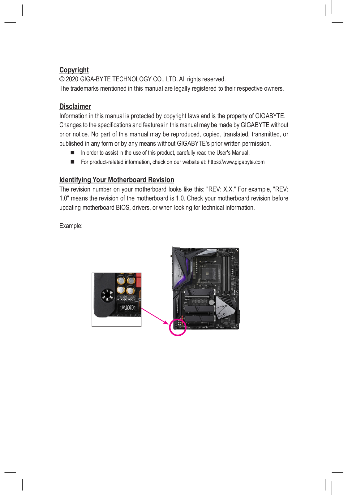
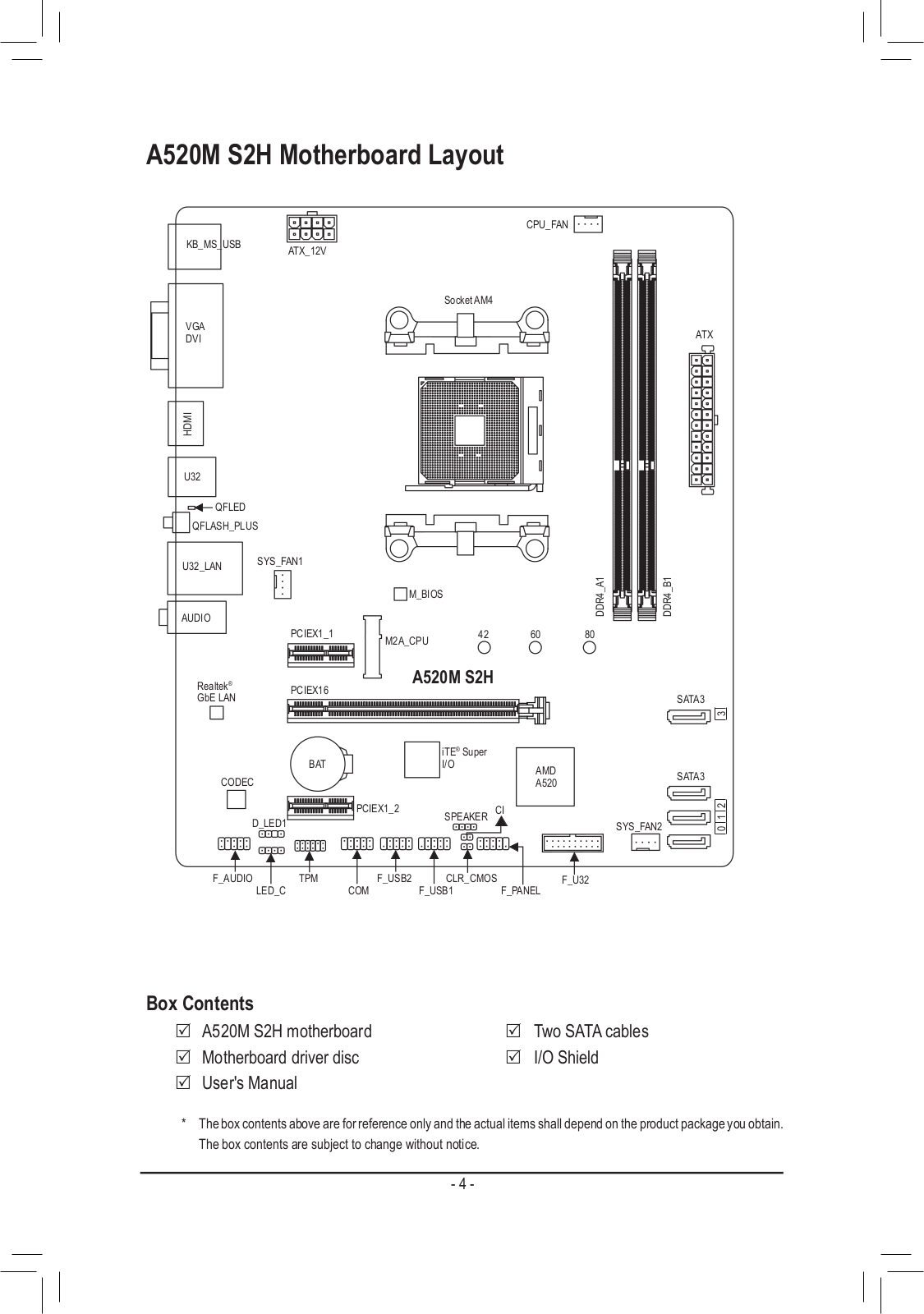
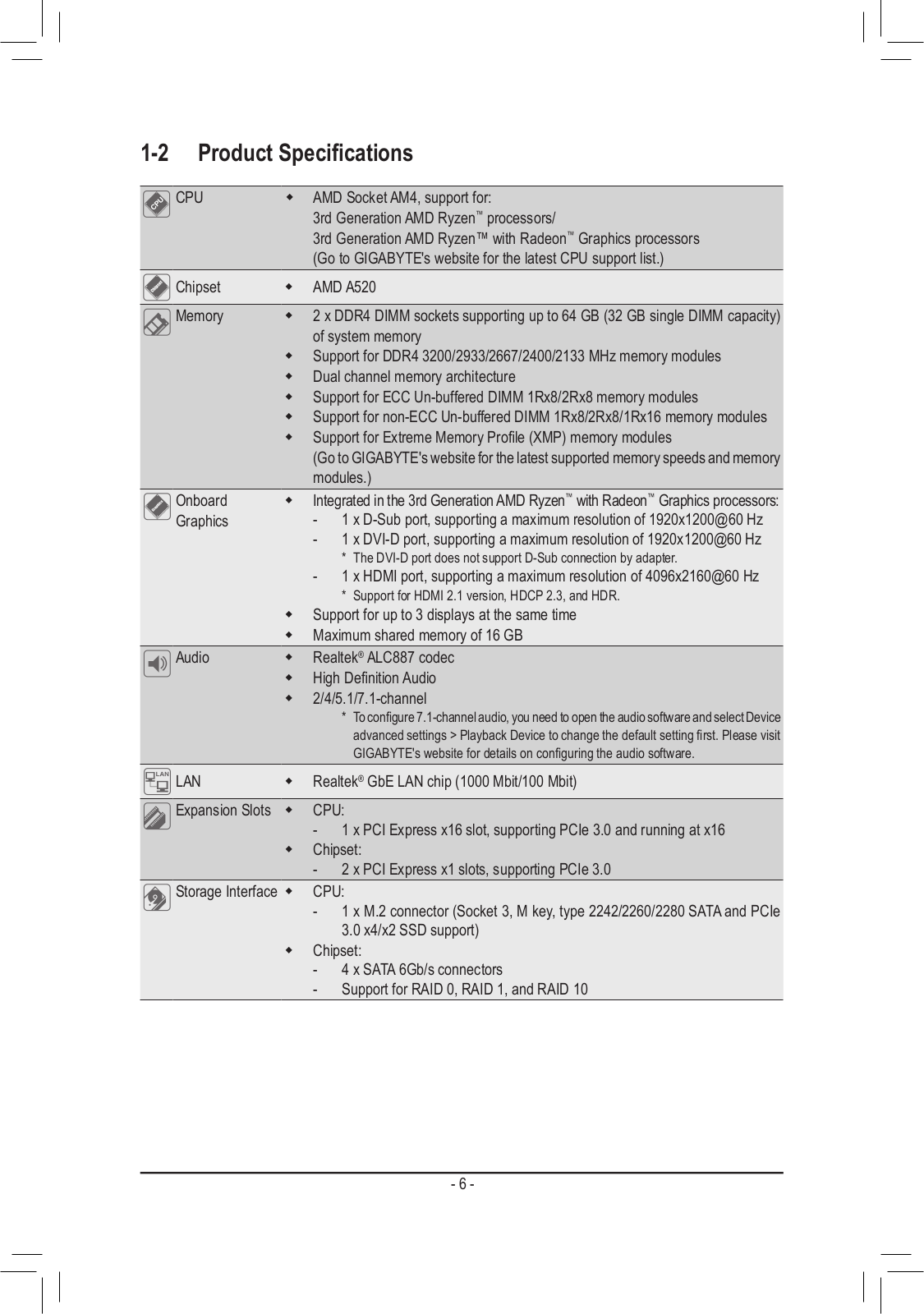
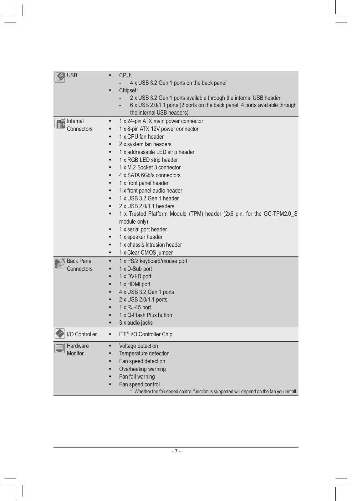
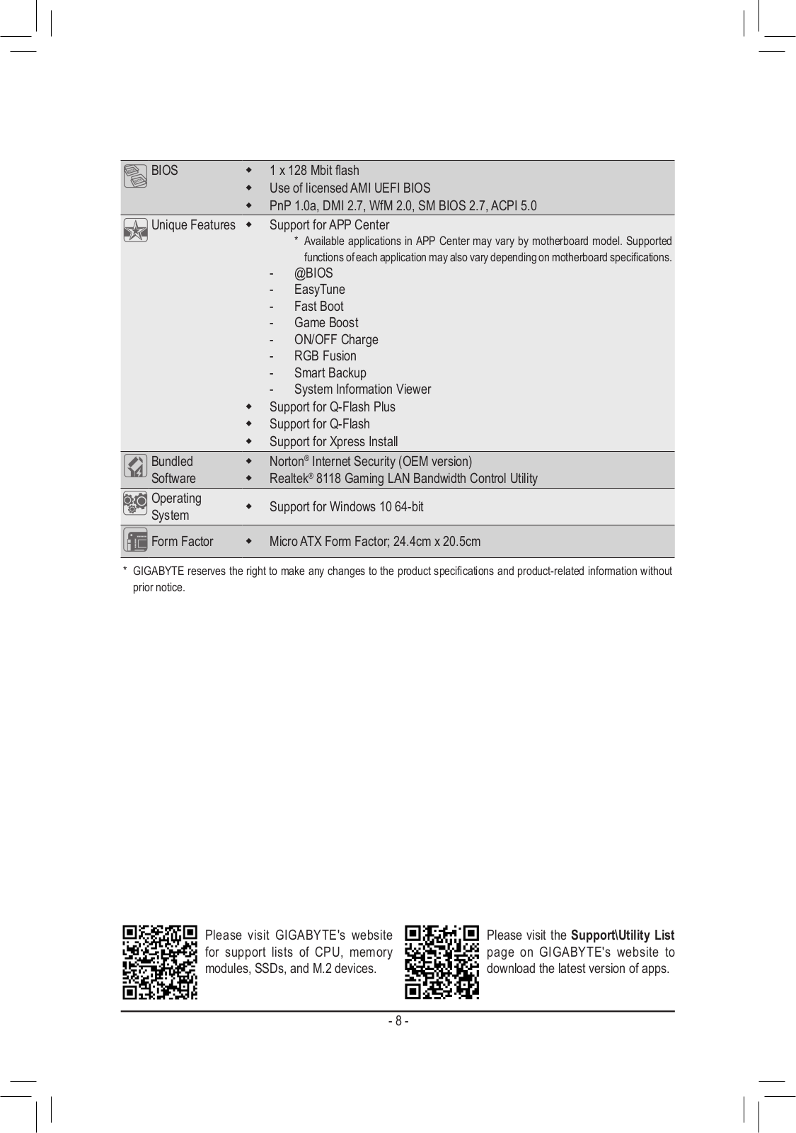
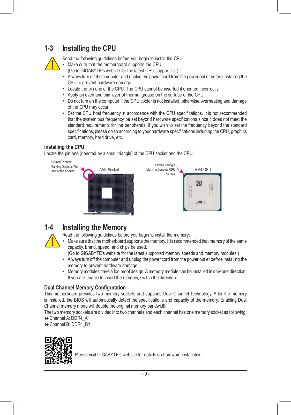
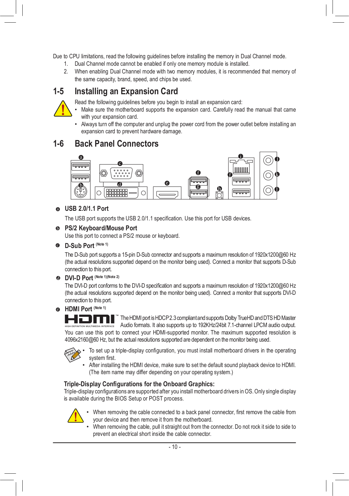
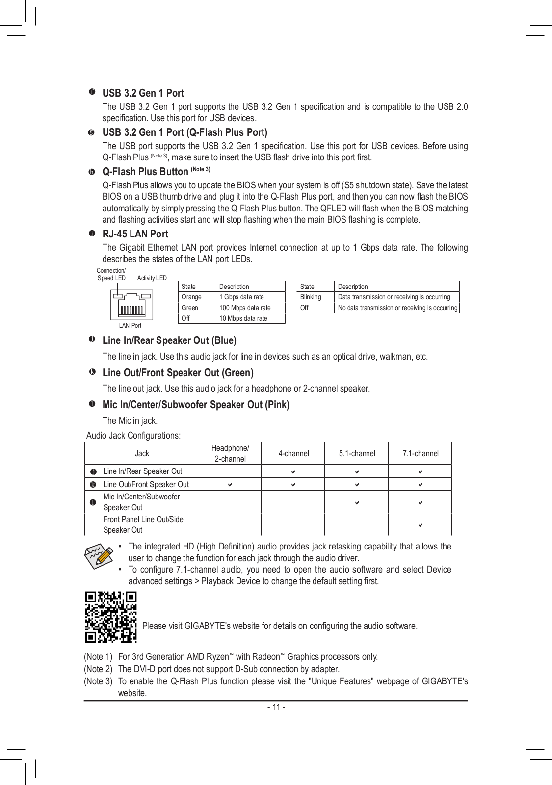
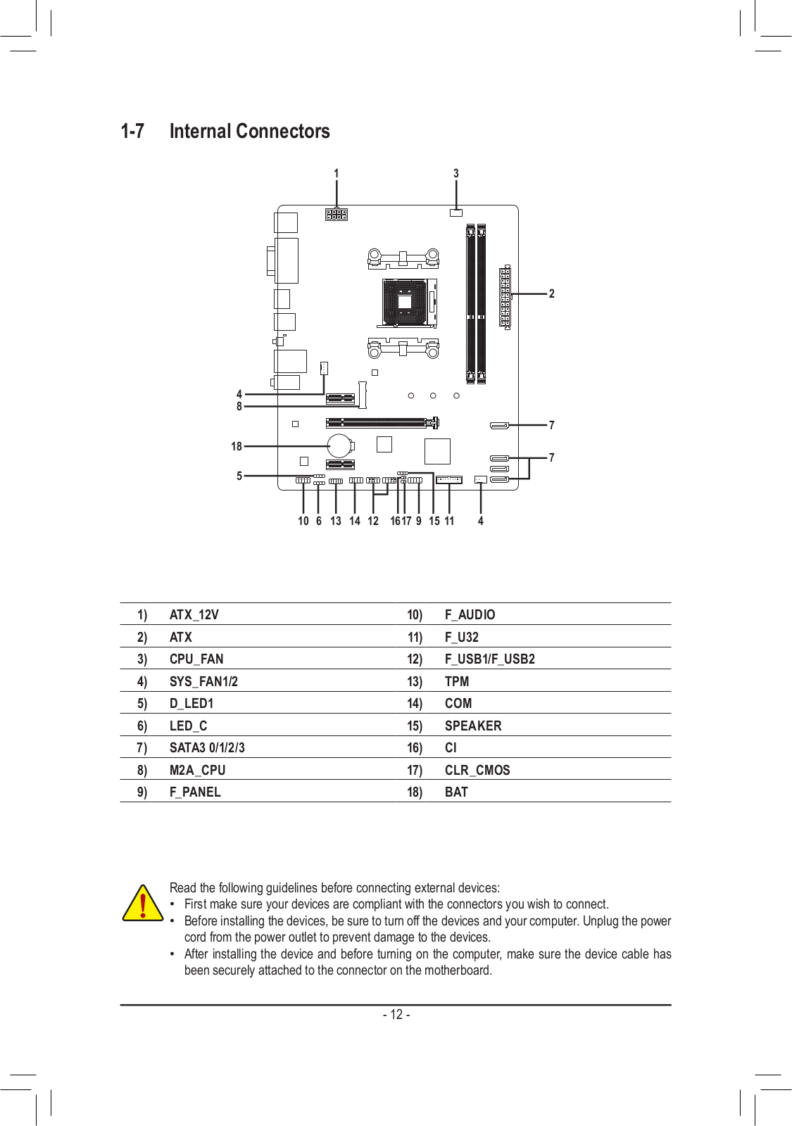
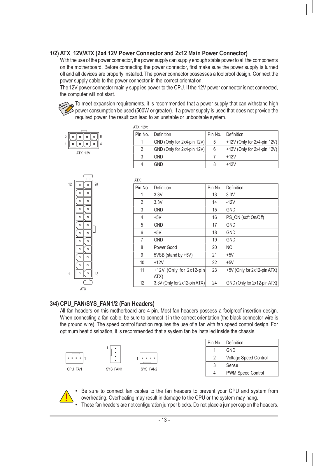
Loading…
+ 28 hidden pages
You need points to download manuals.
1 point = 1 manual.
You can buy points or you can get point for every manual you upload.
Buy points
Upload your manuals
Manuals.eu
- Manuals.eu
- Gigabyte
- Computers & Peripherals
- Mainboards
- Socket AM4
- AMD A520
- A520M S2H (rev. 1.x)
- Manual
×
1
2
3
4
5
6
7
8
9
10
11
12
13
14
15
16
17
18
19
20
21
22
23
24
25
26
27
28
29
30
31
32
33
34
35
36
37
38
39
40
41
⟨
⟩
Copyright © Manuals.eu
Agreement
Privacy Policy
Contact us