
Manual
View the manual for the Gigabyte GA-B85M-D2V here, for free. This user manual comes under the category motherboards and has been rated by 2 people with an average of a 7.5. This manual is available in the following languages: English. Do you have a question about the Gigabyte GA-B85M-D2V?
Ask your question here
Gigabyte GA-B85M-D2V specifications
Below you will find the product specifications and the manual specifications of the Gigabyte GA-B85M-D2V.
Supported memory types
DDR3-SDRAM
Processor manufacturer
Intel
Supported storage drive interfaces
SATA II, SATA III
General
| Brand | Gigabyte |
| Model | GA-B85M-D2V | GA-B85M-D2V |
| Product | motherboard |
| EAN | 4719331837211, 0818313018618 |
| Language | English |
| Filetype | User manual (PDF), Installation Guide (PDF) |
Memory
| Supported memory types | DDR3-SDRAM |
| Memory slots type | DIMM |
| Memory channels | Dual-channel |
| Memory voltage | 1.5 V |
| Supported memory clock speeds | 1333,1600 MHz |
| Maximum internal memory | 16 GB |
| Number of memory slots | 2 |
Processor
| Processor manufacturer | Intel |
| Compatible processor series | Intel Celeron, Intel Pentium |
| Processor socket | LGA 1150 (Socket H3) |
| Intel Core i3/i5/i7/i9 series | i3-4xxx, i5-4xxx, i7-4xxx |
Internal I/O
| USB 2.0 connectors | 2 |
| USB 3.2 Gen 1 (3.1 Gen 1) connectors | 1 |
| CPU fan connector | Yes |
| ATX Power connector (24-pin) | Yes |
| Number of chassis fan connectors | 1 |
| Number of Parallel ATA connectors | 0 |
| Front panel audio connector | Yes |
| Number of SATA II connectors | 2 |
| Number of SATA III connectors | 4 |
| EPS power connector (8-pin) | Yes |
| Serial port headers | 1 |
| Number of SATA connectors | — |
Rear panel I/O ports
| USB 2.0 ports quantity | 4 |
| USB 3.2 Gen 1 (3.1 Gen 1) Type-A ports quantity | 2 |
| Ethernet LAN (RJ-45) ports | 1 |
| eSATA ports quantity | 0 |
| PS/2 ports quantity | 2 |
| Firewire (IEEE 1394) ports | 0 |
| Headphone outputs | 1 |
| Microphone in | Yes |
| VGA (D-Sub) ports quantity | 1 |
| DVI-D ports quantity | 1 |
| HDMI ports quantity | 0 |
Features
| Component for | PC |
| Motherboard chipset family | Intel |
| Motherboard chipset | Intel® B85 |
| Motherboard form factor | micro ATX |
| Cooling type | Passive |
| PC health monitoring | CPU, FAN, Power supply, Temperature |
| Audio output channels | 7.1 channels |
| Audio chip | Realtek ALC887 |
| Windows operating systems supported | Windows 7 Home Basic, Windows 7 Home Basic x64, Windows 7 Home Premium, Windows 7 Home Premium x64, Windows 7 Professional, Windows 7 Professional x64, Windows 7 Starter, Windows 7 Starter x64, Windows 7 Ultimate, Windows 7 Ultimate x64, Windows 8, Windows 8 Enterprise, Windows 8 Enterprise x64, Windows 8 Pro, Windows 8 Pro x64, Windows 8 x64 |
| Power source type | ATX |
Storage controllers
| Supported storage drive interfaces | SATA II, SATA III |
Graphics
| Parallel processing technology support | — |
| Maximum graphics card memory | 1024 MB |
| Graphics card family | Intel |
| Maximum resolution | 1920 x 1200 pixels |
| Discrete graphics support | Yes |
Other features
| Number of processors supported | 1 |
| Serial port via internal header | Yes |
| PCI Express slots quantity | 3 |
Processor special features
| Processor with Intel Graphics Technology required | Yes |
Expansion slots
| PCI Express x1 (Gen 2.x) slots | 2 |
| PCI Express x16 (Gen 3.x) slots | 1 |
Weight & dimensions
Packaging content
| Bundled software | Norton® Internet Security (OEM), Intel Rapid Start Technology, Intel Smart Connect Technology |
Network
| Ethernet LAN | Yes |
| Ethernet interface type | Gigabit Ethernet |
BIOS
| BIOS type | EFI AMI |
| BIOS memory size | 32 Mbit |
| Clear CMOS jumper | No |
show more
Frequently asked questions
Can’t find the answer to your question in the manual? You may find the answer to your question in the FAQs about the Gigabyte GA-B85M-D2V below.
What is the width of the Gigabyte GA-B85M-D2V?
The Gigabyte GA-B85M-D2V has a width of 226 mm.
What is the depth of the Gigabyte GA-B85M-D2V?
The Gigabyte GA-B85M-D2V has a depth of 174 mm.
Is the manual of the Gigabyte GA-B85M-D2V available in English?
Yes, the manual of the Gigabyte GA-B85M-D2V is available in English .
Is your question not listed? Ask your question here

GA-B85M-D2V
User’s Manual
Rev. 1101
12ME-B85MD2V-1101R
Motherboard
GA-B85M-D2V
Motherboard
GA-B85M-D2V
Sept. 6, 2013
Sept. 6, 2013
Copyright
© 2013 GIGA-BYTE TECHNOLOGY CO., LTD. All rights reserved.
The trademarks mentioned in this manual are legally registered to their respective owners.
Disclaimer
Information in this manual is protected by copyright laws and is the property of GIGABYTE.
Changes to the specications and features in this manual may be made by GIGABYTE without prior notice.
No part of this manual may be reproduced, copied, translated, transmitted, or published in any form or by
any means without GIGABYTE’s prior written permission.
In order to assist in the use of this product, carefully read the User’s Manual.
For product-related information, check on our website at: http://www.gigabyte.com
Identifying Your Motherboard Revision
The revision number on your motherboard looks like this: «REV: X.X.» For example, «REV: 1.0» means the
revision of the motherboard is 1.0. Check your motherboard revision before updating motherboard BIOS,
drivers, or when looking for technical information.
Example:

Table of Contents
GA-B85M-D2V Motherboard Layout…………………………………………………………………….4
GA-B85M-D2V Motherboard Block Diagram ………………………………………………………… 5
Chapter 1 Hardware Installation …………………………………………………………………………. 6
1-1 Installation Precautions ……………………………………………………………………….. 6
1-2 Product Specications …………………………………………………………………………. 7
1-3 Installing the CPU ……………………………………………………………………………….. 9
1-4 Installing the Memory ………………………………………………………………………….. 9
1-5 Installing an Expansion Card ………………………………………………………………. 10
1-6 Back Panel Connectors ……………………………………………………………………… 10
1-7 Internal Connectors …………………………………………………………………………….11
Chapter 2 BIOS Setup …………………………………………………………………………………….. 17
2-1 Startup Screen ………………………………………………………………………………….. 17
2-2 M.I .T. ……………………………………………………………………………………………….. 18
2-3 System Information ……………………………………………………………………………. 22
2-4 BIOS Features ………………………………………………………………………………….. 23
2-5 Peripherals ……………………………………………………………………………………….. 26
2-6 Power Management ……………………………………………………………………………28
2-7 Save & Exit ………………………………………………………………………………………. 30
Chapter 3 Appendix ………………………………………………………………………………………… 31
Drivers Installation ………………………………………………………………………………………. 31
Regulatory Statements ………………………………………………………………………………… 32
Contact Us …………………………………………………………………………………………………. 36
— 3 —
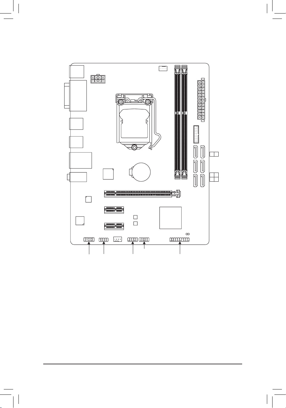
GA-B85M-D2V Motherboard Layout
KB_MS
DVI
R_USB
R_USB30
USB_LAN
AUDIO
CODEC
ATX_12V_2X4
VGA
Realtek®
GbE LAN
F_AUDIO
iTE
Super I/O
PCIEX16
PCIEX1_1
PCIEX1_2
COM
®
SYS_FAN
LGA1150
GA-B85M-D2V
BAT
B_BIOS
M_BIOS
F_USB1
F_USB2
CPU_FAN
Intel® B85
DDR3_1
CLR_CMOS
F_PANEL
ATX
F_USB30
DDR3_2
SATA 2
5 4
SATA 3
3 2
1 0
Box Contents
5 GA-B85M-D2V motherboard
5 Motherboard driver disk 5 Two SATA cables
5 User’s Manual 5 I/O Shield
The box contents above are for reference only and the actual items shall depend on the product package you obtain.
The box contents are subject to change without notice.
— 4 —
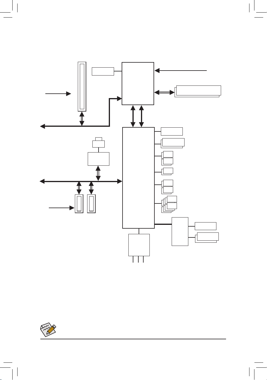
GA-B85M-D2V Motherboard Block Diagram
1 PCI Express x16
DVI-D
CPU CLK+/- (100 MHz)
PCIe CLK
(100 MHz)
PCI Express Bus
PCI Express Bus
PCIe CLK
(100 MHz)
2 PCI Express x1
x16
LAN
RJ45
Realtek®
GbE LAN
x1
x1x1
LGA1150 CPU
DMI 2.0
Intel® B85
CODEC
FDI
D-Sub
Dual BIOS
LPC Bus
DDR3 1600/1333 MHz
Dual Channel Memory
4 SATA 6Gb/s
2 SATA 3Gb/s
4 USB 3.0/2.0
8 USB 2.0/1.1
iTE®
Super
I/O
COM
PS/2 KB/Mouse
Speaker Out)
MIC (Center/Subwoofer
Line In (Rear Speaker Out)
Line Out (Front Speaker Out)
For detailed product information/limitation(s), refer to «1-2 Product Specications.»
— 5 —

Chapter 1 Hardware Installation
1-1 Installation Precautions
The motherboard contains numerous delicate electronic circuits and components which can become
damaged as a result of electrostatic discharge (ESD). Prior to installation, carefully read the user’s
manual and follow these procedures:
• Prior to installation, make sure the chassis is suitable for the motherboard.
• Prior to installation, do not remove or break motherboard S/N (Serial Number) sticker or
warranty sticker provided by your dealer. These stickers are required for warranty validation.
• Always remove the AC power by unplugging the power cord from the power outlet before
installing or removing the motherboard or other hardware components.
• When connecting hardware components to the internal connectors on the motherboard, make
sure they are connected tightly and securely.
• When handling the motherboard, avoid touching any metal leads or connectors.
• It is best to wear an electrostatic discharge (ESD) wrist strap when handling electronic com-
ponents such as a motherboard, CPU or memory. If you do not have an ESD wrist strap, keep
your hands dry and rst touch a metal object to eliminate static electricity.
• Prior to installing the motherboard, please have it on top of an antistatic pad or within an
electrostatic shielding container.
• Before unplugging the power supply cable from the motherboard, make sure the power supply
has been turned off.
• Before turning on the power, make sure the power supply voltage has been set according to
the local voltage standard.
• Before using the product, please verify that all cables and power connectors of your hardware
components are connected.
• To prevent damage to the motherboard, do not allow screws to come in contact with the
motherboard circuit or its components.
• Make sure there are no leftover screws or metal components placed on the motherboard or
within the computer casing.
• Do not place the computer system on an uneven surface.
• Do not place the computer system in a high-temperature environment.
• Turning on the computer power during the installation process can lead to damage to system
components as well as physical harm to the user.
• If you are uncertain about any installation steps or have a problem related to the use of the
product, please consult a certied computer technician.
— 6 —
1-2 ProductSpecications
CPU Support for Intel® Core™ i7 processors/Intel® Core™ i5 processors/
Intel® Core™ i3 processors/Intel® Pentium® processors/
Intel® Celeron® processors in the LGA1150 package
(Go to GIGABYTE’s website for the latest CPU support list.)
L3 cache varies with CPU
Chipset Intel® B85 Express Chipset
Memory 2 x 1.5V DDR3 DIMM sockets supporting up to 16 GB of system memory
Onboard
Graphics
Audio Realtek® ALC887 codec
LAN Realtek® GbE LAN chip (10/100/1000 Mbit)
Expansion Slots 1 x PCI Express x16 slot, running at x16
Storage Interface Chipset:
USB Chipset:
Internal
Connectors
* Due to a Windows 32-bit operating system limitation, when more than 4 GB of physical
memory is installed, the actual memory size displayed will be less than the size of
the physical memory installed.
Dual channel memory architecture
Support for DDR3 1600/1333 MHz memory modules
Support for non-ECC memory modules
Support for Extreme Memory Prole (XMP) memory modules
(Go to GIGABYTE’s website for the latest supported memory speeds and memory
modules.)
Integrated Graphics Processor:
— 1 x D-Sub port, supporting a maximum resolution of 1920×1200
— 1 x DVI-D port, supporting a maximum resolution of 1920×1200
* The DVI-D port does not support D-Sub connection by adapter.
— Maximum shared memory of 1 GB
High Denition Audio
2/4/5.1/7.1-channel
* To congure 7.1-channel audio, you have to use an HD front panel audio module
and enable the multi-channel audio feature through the audio driver.
(The PCI Express x16 slot conforms to PCI Express 3.0 standard.)
2 x PCI Express x1 slot
(All PCI Express x1 slots conform to PCI Express 2.0 standard.)
— 4 x SATA 6Gb/s connectors (SATA3 0~SATA3 3)
— 2 x SATA 3Gb/s connectors (SATA2 4~SATA2 5)
— 4 USB 3.0/2.0 ports (2 ports on the back panel, 2 ports available through the
internal USB header)
— 8 USB 2.0/1.1 ports (4 ports on the back panel, 4 ports available through the
internal USB headers)
1 x 24-pin ATX main power connector
1 x 8-pin ATX 12V power connector
4 x SATA 6Gb/s connectors
2 x SATA 3Gb/s connectors
1 x CPU fan header
1 x system fan header
1 x front panel header
1 x front panel audio header
— 7 —

Internal
Connectors
1 x USB 3.0/2.0 header
2 x USB 2.0/1.1 headers
1 x serial port header
1 x Clear CMOS jumper
Back Panel
Connectors
1 x PS/2 keyboard port
1 x PS/2 mouse port
1 x D-Sub port
1 x DVI-D port
2 x USB 3.0/2.0 ports
4 x USB 2.0/1.1 ports
1 x RJ-45 port
3 x audio jacks (Line In, Line Out, Mic In)
I/O Controller iTE® I/O Controller Chip
Hardware
Monitor
System voltage detection
CPU/System temperature detection
CPU/System fan speed detection
CPU/System overheating warning
CPU/System fan fail warning
CPU/System fan speed control
* Whether the fan speed control function is supported will depend on the cooler you install.
BIOS 2 x 32 Mbit ash
Use of licensed AMI EFI BIOS
Support for DualBIOS
™
PnP 1.0a, DMI 2.0, SM BIOS 2.6, ACPI 2.0a
Unique Features Support for Q-Flash
Support for Xpress Install
Support for APP Center
* Available applications in APP Center may differ by motherboard model. Supported
functions of each application may also differ depending on motherboard specications.
— @BIOS
— EasyTune
— EZ Setup
— USB Blocker
— Smart TimeLock
— Smart Recovery 2
Support for ON/OFF Charge
Bundled
Software
Operating
System
Norton® Internet Security (OEM version)
Intel® Rapid Start Technology
Intel® Smart Connect Technology
Support for Windows 8.1/8/7
* I f you plan to install Windows 8.1, please download the latest drivers from
GIGABYTE’s website.
Form Factor Micro ATX Form Factor; 22.6cm x 17.4cm
* GIGABYTE reserves the right to make any changes to the product specications and product-related information without
prior notice.
* Please visit the Support & Downloads\Utility page on GIGABYTE’s website to check the supported operating system(s)
for the software listed in the «Unique Features» and «Bundled Software» columns.
— 8 —
1-3 Installing the CPU
Read the following guidelines before you begin to install the CPU:
• Make sure that the motherboard supports the CPU.
(Go to GIGABYTE’s website for the latest CPU support list.)
• Always turn off the computer and unplug the power cord from the power outlet before installing the
CPU to prevent hardware damage.
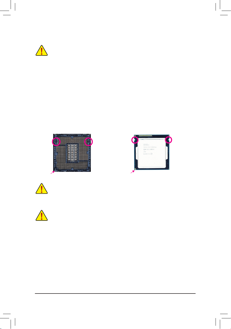
• Locate the pin one of the CPU. The CPU cannot be inserted if oriented incorrectly. (Or you may
locate the notches on both sides of the CPU and alignment keys on the CPU socket.)
• Apply an even and thin layer of thermal grease on the surface of the CPU.
• Do not turn on the computer if the CPU cooler is not installed, otherwise overheating and damage
of the CPU may occur.
• Set the CPU host frequency in accordance with the CPU specications. It is not recommended
that the system bus frequency be set beyond hardware specications since it does not meet the
standard requirements for the peripherals. If you wish to set the frequency beyond the standard
specications, please do so according to your hardware specications including the CPU, graphics
card, memory, hard drive, etc.
Installing the CPU
Locate the alignment keys on the motherboard CPU socket and the notches on the CPU.
LGA1150 CPU Socket
Pin One Corner of the CPU Socket
Alignment KeyAlignment Key
Notch
Triangle Pin One Marking on the CPU
LGA1150 CPU
Notch
Do not remove the CPU socket cover before inserting the CPU. It may pop off from the load plate
automatically during the process of re-engaging the lever after you insert the CPU.
1-4 Installing the Memory
Read the following guidelines before you begin to install the memory:
• Make sure that the motherboard supports the memory. It is recommended that memory of the
same capacity, brand, speed, and chips be used.
(Go to GIGABYTE’s website for the latest supported memory speeds and memory modules.)
• Always turn off the computer and unplug the power cord from the power outlet before installing the
memory to prevent hardware damage.
• Memory modules have a foolproof design. A memory module can be installed in only one direction.
If you are unable to insert the memory, switch the direction.
DualChannelMemoryConguration
This motherboard provides two DDR3 memory sockets and supports Dual Channel Technology. After the memory
is installed, the BIOS will automatically detect the specications and capacity of the memory. Enabling Dual
Channel memory mode will double the original memory bandwidth.
The two DDR3 memory sockets are divided into two channels and each channel has one memory socket as
following:
Channel A: DDR3_1
Channel B: DDR3_2
— 9 —
Due to CPU limitations, read the following guidelines before installing the memory in Dual Channel mode.
1. Dual Channel mode cannot be enabled if only one DDR3 memory module is installed.
2. When enabling Dual Channel mode with two memory modules, it is recommended that memory of
the same capacity, brand, speed, and chips be used for optimum performance.
1-5 Installing an Expansion Card
Read the following guidelines before you begin to install an expansion card:
• Make sure the motherboard supports the expansion card. Carefully read the manual that came
with your expansion card.
• Always turn off the computer and unplug the power cord from the power outlet before installing an
expansion card to prevent hardware damage.
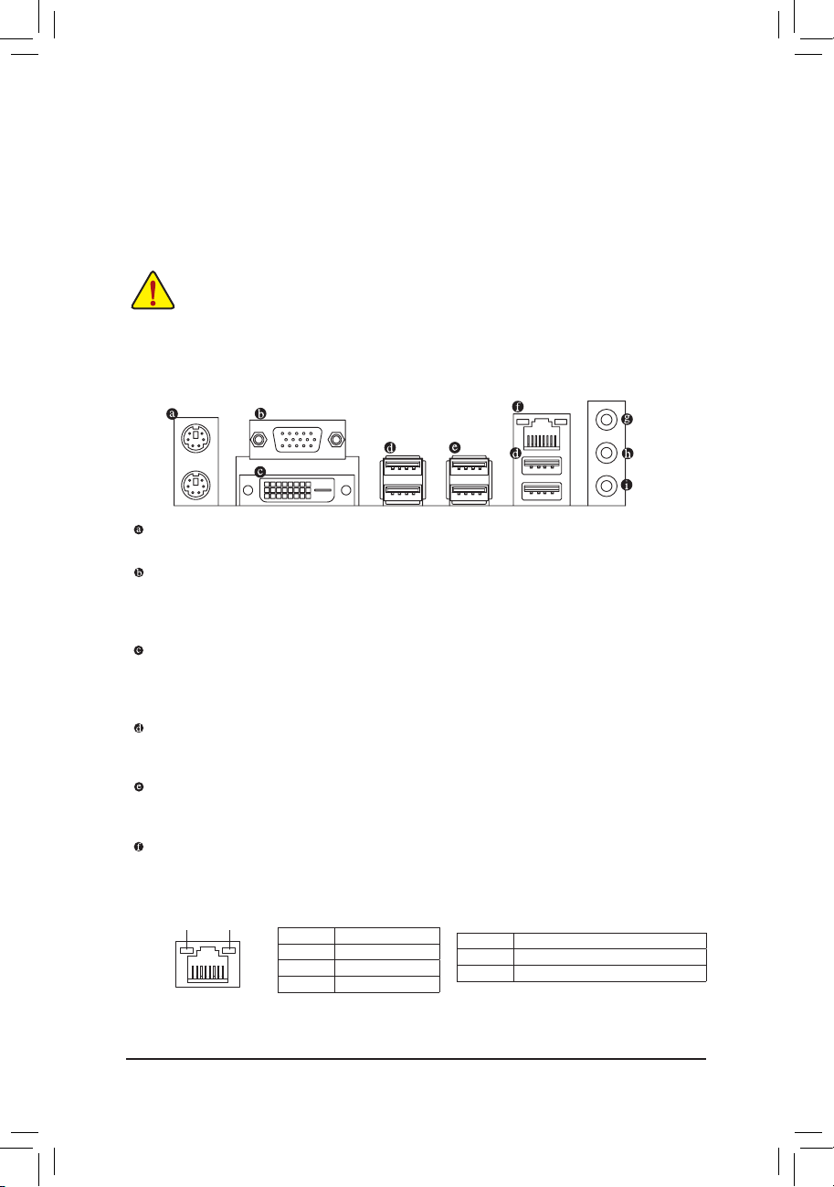
1-6 Back Panel Connectors
PS/2 Keyboard and PS/2 Mouse Port
Use the upper port (green) to connect a PS/2 mouse and the lower port (purple) to connect a PS/2 keyboard.
D-Sub Port
The D-Sub port supports a 15-pin D-Sub connector and supports a maximum resolution of 1920×1200
(the actual resolutions supported depend on the monitor being used). Connect a monitor that supports
D-Sub connection to this port.
DVI-D Port
The DVI-D port conforms to the DVI-D specication and supports a maximum resolution of 1920×1200
(the actual resolutions supported depend on the monitor being used). Connect a monitor that supports
DVI-D connection to this port.
USB 2.0/1.1 Port
The USB port supports the USB 2.0/1.1 specication. Use this port for USB devices such as a USB
keyboard/mouse, USB printer, USB ash drive and etc.
USB 3.0/2.0 Port
The USB 3.0 port supports the USB 3.0 specication and is compatible to the USB 2.0/1.1 specication.
Use this port for USB devices such as a USB keyboard/mouse, USB printer, USB ash drive and etc.
RJ-45 LAN Port
The Gigabit Ethernet LAN port provides Internet connection at up to 1 Gbps data rate. The following
describes the states of the LAN port LEDs.
Connection/
Speed LED
LAN Port
(Note)
Activity LED
Connection/Speed LED:
State Description
Orange 1 Gbps data rate
Green 100 Mbps data rate
Off 10 Mbps data rate
Activity LED:
State Description
Blinking Data transmission or receiving is occurring
Off No data transmission or receiving is occurring
(Note) The DVI-D port does not suppor t D-Sub connection by adapter.
— 10 —
Line In Jack (Blue)
The default line in jack. Use this audio jack for line in devices such as an optical drive, walkman, etc.
Line Out Jack (Green)
The default line out jack. Use this audio jack for a headphone or 2-channel speaker. This jack can be used
to connect front speakers in a 4/5.1/7.1-channel audio conguration.
Mic In Jack (Pink)
The default Mic in jack. Microphones must be connected to this jack.
To congure 7.1-channel audio, you have to use an HD front panel audio module and enable the
multi-channel audio feature through the audio driver.
• When removing the cable connected to a back panel connector, rst remove the cable from your
device and then remove it from the motherboard.
• When removing the cable, pull it straight out from the connector. Do not rock it side to side to prevent
an electrical short inside the cable connector.
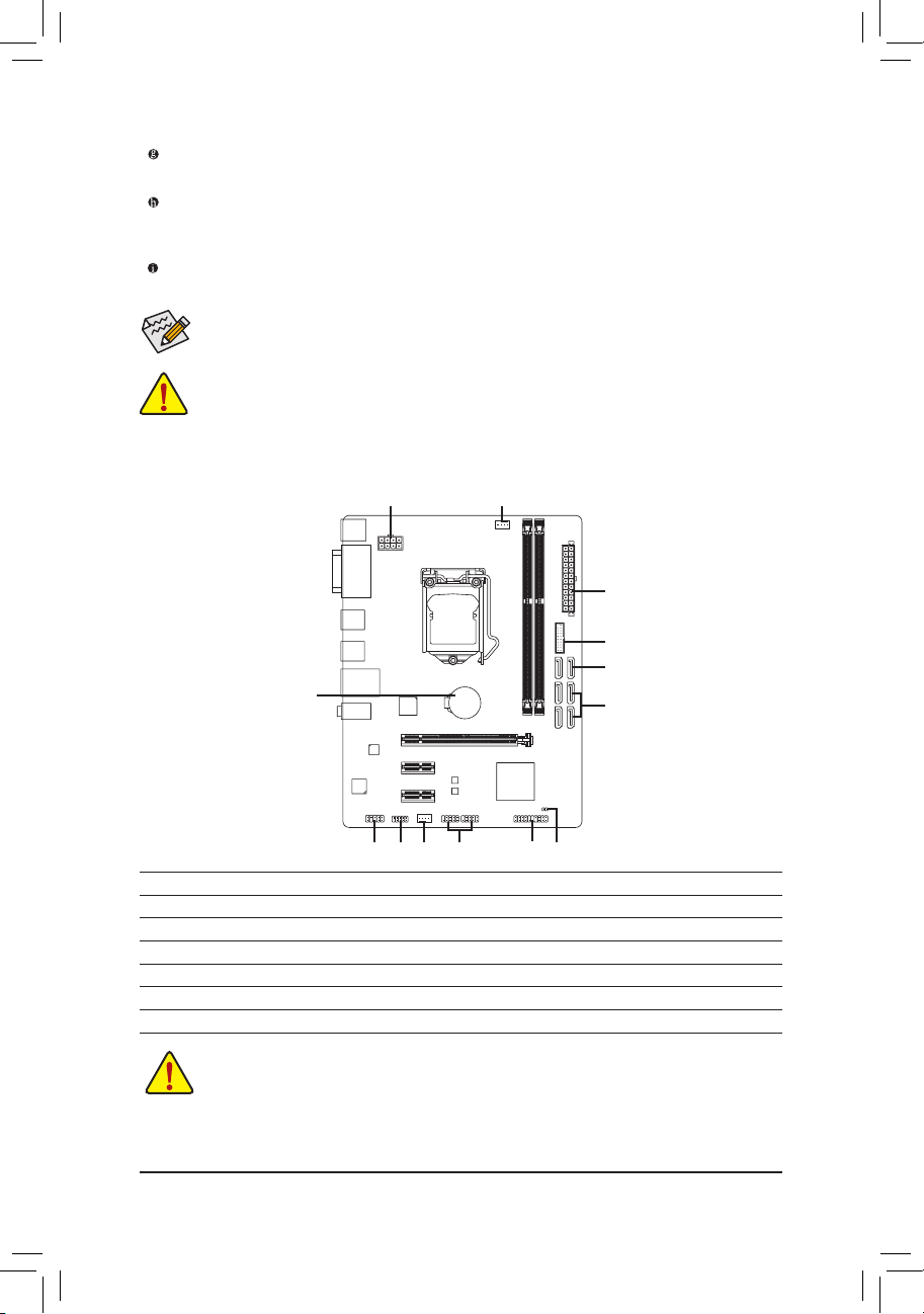
1-7 Internal Connectors
1
13
3
2
10
6
5
1) ATX_12V_2X4
2) ATX
3) CPU_FAN
4) SYS_FAN
5) SATA3 0/1/2/3
6) SATA2 4/5
4
8
11
12
7
9
 F_AUDIO
9) CLR_CMOS
10) F_USB30
11) F_USB1/F_USB2
12) COM
13) BAT
7) F_PANEL
Read the following guidelines before connecting external devices:
• First make sure your devices are compliant with the connectors you wish to connect.
• Before installing the devices, be sure to turn off the devices and your computer. Unplug the power
cord from the power outlet to prevent damage to the devices.
• After installing the device and before turning on the computer, make sure the device cable has
been securely attached to the connector on the motherboard.
— 11 —
Loading…
-
Page 1: Gigabyte GA-B85M-D2V
GA-B85M-D2V User’s Manual Rev . 1 1 01 1 2ME-B85MD2V — 1 1 01 R[…]
-
Page 2: Gigabyte GA-B85M-D2V
Motherboard GA-B85M-D2V Sept. 6, 2013 Sept. 6, 2013 Motherboard GA-B85M-D2V Copyright © 2013 GIGA-BYTE TECHNOLOGY CO., L TD. All rights reserved. The trademarks mentioned in this manual are legally registered to their respective owners. Disclaimer Information in this manual is protected by copyright laws and is the property of GIGABYTE. Changes to[…]
-
Page 3: Gigabyte GA-B85M-D2V
— 3 — T able of Contents GA — B85 M — D2V Moth erboar d Layout……………………………………………………………………. 4 GA — B85 M — D2V Moth erboar d Bloc k Diagram ………………………………………………………… 5 Chapter 1 Hardware Inst allation ………………………………………………….[…]
-
Page 4: Gigabyte GA-B85M-D2V
— 4 — GA- B85 M — D2V Mothe rboa rd Layout The box contents above are for reference only and the actual items shall depend on the product package you obtain. The box contents are subject to change without notice. Box Contents 5 GA-B85M-D2V motherboard 5 Motherboard driver disk 5 T wo SA T A cables 5 User’s Manual 5 I/O Shield KB_MS CPU_F AN LG[…]
-
Page 5: Gigabyte GA-B85M-D2V
— 5 — GA- B85M — D2V Motherboard Block Diagram PS/2 KB/Mouse LGA1 150 CPU DMI 2.0 FDI CPU CLK+/- (100 MHz) Dual BIOS DDR3 1600/1333 MHz Dual Channel Memory COM LPC Bus Intel ® B85 iTE ® Super I/O PCIe CLK (100 MHz) PCI Express Bus 1 PCI Express x16 x1 LAN RJ45 Realtek ® GbE LAN PCI Express Bus x16 D-Sub 4 SA T A 6Gb/s DVI-D 8 USB 2.0/1.1 4 USB 3[…]
-
Page 6: Gigabyte GA-B85M-D2V
— 6 — Chapter 1 Hardware Installation 1- 1 Installation Precautions The motherboard contains numerous delicate electronic circuits and components which can become damaged as a result of electrostatic discharge (ESD). Prior to installation, carefully read the user’s manual and follow these procedures: • Prior to installation, make sure the ch[…]
-
Page 7: Gigabyte GA-B85M-D2V
— 7 — 1- 2 P roductSpe cications CPU Support for Intel® Core™ i7 processors/Intel® Core™ i5 processors/ Intel ® Core ™ i3 processors/Intel ® Pentium ® processors/ Intel ® Celeron ® processors in the LGA1 150 package (Go to GIGABYTE’s website for the latest CPU support list.) L3 cache varies with CPU Chipset In[…]
-
Page 8: Gigabyte GA-B85M-D2V
— 8 — Internal Connectors 1 x USB 3.0/2.0 header 2 x USB 2.0/1.1 headers 1 x serial port header 1 x Clear CMOS jumper Back Panel Connectors 1 x PS/2 keyboard port 1 x PS/2 mouse port 1 x D-Sub port 1 x DVI-D port 2 x USB 3.0/2.0 ports 4 x USB 2.0/1.1 ports 1 x RJ-45 port 3 x audio jacks (Line In, Line[…]
-
Page 9: Gigabyte GA-B85M-D2V
— 9 — 1-3 Installing the CPU Read the following guidelines before you begin to install the CPU: • Make sure that the motherboard supports the CPU. (Go to GIGABYTE’s website for the latest CPU support list.) • Always turn off the computer and unplug the power cord from the power outlet before installing the CPU to prevent hardware damage. ?[…]
-
Page 10: Gigabyte GA-B85M-D2V
— 10 — 1-5 Installing an Expansion Card Read the following guidelines before you begin to install an expansion card: • Make sure the motherboard supports the expansion card. Carefully read the manual that came with your expansion card. • Always turn off the computer and unplug the power cord from the power outlet before installing an expansion […]
-
Page 11: Gigabyte GA-B85M-D2V
— 1 1 — • When removing the cable connected to a back panel connector, rst remove the cable from your device and then remove it from the motherboard. • When removing the cable, pull it straight out from the connector . Do not rock it side to side to prevent an electrical short inside the cable connector . Line In Jack (Blue) The default line[…]
-
Page 12: Gigabyte GA-B85M-D2V
— 12 — 1/2) A TX_12V_2X4/A TX (2×4 12V Power Connector and 2×12 Main Power Connector) With the use of the power connector, the power supply can supply enough stable power to all the components on the motherboard. Before connecting the power connector, rst make sure the power supply is turned off and all devices are properly installed. The power […]
-
Page 13: Gigabyte GA-B85M-D2V
— 13 — 5) SA T A3 0/1/2/3 (SA T A 6Gb/s Connectors) The SA T A connectors conform to SA T A 6Gb/s standard and are compatible with SA T A 3Gb/s and SA T A 1.5Gb/s standard. Each SA T A connector supports a single SA T A device. Pin No. Denition Pin No. Denition 1 GND 5 RXN 2 TXP 6 RXP 3 TXN 7 GND 4 GND S ATA 3 S ATA 2 3 2 1 0 5 4 7 7 DEBUG PO[…]
-
Page 14: Gigabyte GA-B85M-D2V
— 14 — 7) F_P ANEL (Front Panel Header) Connect the power switch, reset switch, speaker , and system status indicator on the chassis to this header according to the pin assignments below . Note the positive and negative pins before connecting the cables. The front panel design may differ by chassis. A front panel module mainly consists of power swi[…]
-
Page 15: Gigabyte GA-B85M-D2V
— 15 — 9) CLR_CMOS (Clear CMOS Jumper) Use this jumper to clear the BIOS conguration and reset the CMOS values to factory defaults. T o clear the CMOS values, use a metal object like a screwdriver to touch the two pins for a few seconds. • Always turn off your computer and unplug the power cord from the pow er outlet before clearing the CMOS v[…]
-
Page 16: Gigabyte GA-B85M-D2V
— 16 — 13) BA T (Battery) The battery provides power to keep the values (such as BIOS congurations, date, and time information) in the CMOS when the computer is turned off. Replace the battery when the battery voltage drops to a low level, or the CMOS values may not be accurate or may be lost. Y ou may clear the CMOS values by removing the batte[…]
-
Page 17: Gigabyte GA-B85M-D2V
— 17 — Chapter 2 BIOS Setup • Because BIOS ashing is potentially risky, if you do not encounter problems using the current version of BIOS, it is recommended that you not ash the BIOS. T o ash the BIOS, do it with caution. Inadequate BIOS ashing may result in system malfunction. • It is recommended that you not alter the default set[…]
-
Page 18: Gigabyte GA-B85M-D2V
— 18 — 2- 2 M.I. T . Whether the system will work stably with the overclock/overvoltage settings you made is dependent on your overall system congurations. Incorrectly doing overclock/overvoltage may result in damage to CPU, chipset, or memory and reduce the useful life of these components. This page is for advanced users only and we recommend y[…]
-
Page 19: Gigabyte GA-B85M-D2V
— 19 — (Not e) This ite m is pr esen t only w hen yo u inst all a C PU th at supp or t s thi s feat ure. For m ore i nfor ma tio n abo ut Intel ® CPUs’ u niq ue feat ure s, ple ase v isit I ntel ‘s web site. ` Advanced CPU Core Settings & CPU Clock Ratio, CPU Frequency The settings above are synchronous to those under the same items […]
-
Page 20: Gigabyte GA-B85M-D2V
— 20 — (Note) This item is present only when you install a CPU and a memory module that support this feature. (Not e) Thi s item i s pre sent o nly w hen yo u inst all a C PU that s upp or t s this f eatu re. For m ore in for mat ion about Int el ® CPUs’ u niq ue feat ure s, ple ase v isit I ntel ‘s web site. ` Advanced Memory Settings &[…]
-
Page 21: Gigabyte GA-B85M-D2V
— 21 — ` PC Health Status & Reset Case Open Status Disabled Keeps or clears the record of previous chassis intrusion status. (Default) Enabled Clears the record of previous chassis intrusion status and the Case Open eld will show «No» at next boot. & Case Open Displays the detection status of the chassis intrusion detec[…]
-
Page 22: Gigabyte GA-B85M-D2V
— 22 — & Fan Speed Percentage Allows you to control the system fan speed. This item is congurable only when System Fan Speed Control is set to Manual . Options are: 0.75 PWM value / o C ~ 2.50 PWM value / o C. ` Miscellaneous Settings & PCIeSlotConguration Allows you to set the operation mode of the PCI Express slots to Gen 1, G[…]
-
Page 23: Gigabyte GA-B85M-D2V
— 23 — 2- 4 BIOS Features & Boot Option Priorities Species the overall boot order from the available devices. For example, you can set hard drive as the rst priority ( Boot Option #1 ) and DVD ROM drive as the second priority ( Boot Option #2 ). The list only displays the device with the highest priority for a specic type. For example,[…]
-
Page 24: Gigabyte GA-B85M-D2V
— 24 — & Fast Boot Enables or disables Fast Boot to shorten the OS boot process. Ultra Fast provides the fastest bootup speed. (Default: Disabled) & VGA Support Allows you to select which type of operating system to boot. Auto Enables legacy option ROM only . EFI Driver Enables EFI option ROM. (Default) This item is congurable on[…]
-
Page 25: Gigabyte GA-B85M-D2V
— 25 — & Windows 8 Features Allows you to select the operating system to be installed. (Default: Other OS) & CSM Support Enables or disables UEFI CSM (Compatibility Support Module) to support a legacy PC boot process. Always Enables UEFI CSM. (Default) Never Disables UEFI CSM and supports UEFI BIOS boot process only . This item is c[…]
-
Page 26: Gigabyte GA-B85M-D2V
— 26 — & Initial Display Output Species the rst initiation of the monitor display from the installed PCI Express graphics card or the onboard graphics. IGFX Sets the onboard graphics as the rst display . PCIe 1 Slot Sets the graphics card on the PCIEX16 slot as the rst display . (Default) & XHCI Mode Allows you to determ[…]
-
Page 27: Gigabyte GA-B85M-D2V
— 27 — E nab led All shared ports are eventually routed to the xHCI controller during the BIOS boot process. If BIOS does not have pre-boot support for the xHCI controller , it should initially route the sharable ports to the EHCI controller and then prior to OS boot it should route the ports to xHCI controller . Note: OS has to provide support[…]
-
Page 28: Gigabyte GA-B85M-D2V
— 28 — (AHCI) is an interface specication that allows the storage driver to enable advanced Serial A T A features such as Native Command Queuing and hot plug. (Default) ` Serial A T A Port 0/1/2/3/4/5 & Port 0/1/2/3/4/5 Enables or disables each SA T A port. (Default: Enabled) & Hot plug Enables or disable the hot plug capability for each[…]
-
Page 29: Gigabyte GA-B85M-D2V
— 29 — & Resume by Alarm Determines whether to power on the system at a desired time. (Default: Disabled) If enabled, set the date and time as following: Wake up day: T urn on the system at a specic time on each day or on a specic day in a month. Wake up hour/minute/second: Set the time at which the system will be powered on autom[…]
-
Page 30: Gigabyte GA-B85M-D2V
— 30 — & Save & Exit Setup Press <Enter> on this item and select Ye s . This saves the changes to the CMOS and exits the BIOS Setup program. Select No or press <Esc> to return to the BIOS Setup Main Menu. & Exit Without Saving Press <Enter> on this item and select Ye s . This exits the BIOS Setup without saving the cha[…]
-
Page 31: Gigabyte GA-B85M-D2V
— 31 — Chapter 3 Appendix Drivers Installation • Before installing the drivers, rst install the operating system. (The following instructions use Windows 8 as the example operating system.) • After installing the operating system, insert the motherboard driver disk into your optical drive. Click on the message «T ap to choose what happe[…]
-
Page 32: Gigabyte GA-B85M-D2V
— 32 — Regulator y Statement s Regulatory Notices This document must not be copied without our written permission, and the contents there of must not be imparted to a third party nor be used for any unauthorized purpose. Contravention will be prosecuted. We believe that the information contained herein was accurate in all respects at the time of pr[…]
-
Page 33: Gigabyte GA-B85M-D2V
— 33 -[…]
-
Page 34: Gigabyte GA-B85M-D2V
— 34 -[…]
-
Page 35: Gigabyte GA-B85M-D2V
— 35 -[…]
-
Page 36: Gigabyte GA-B85M-D2V
— 36 — Conta ct Us GIGA-BYTE TECHNOLOGY CO., L TD. Add res s: N o.6, B ao Ch ian g Roa d, Hs in -Tien D ist ., New Taipe i Cit y 231, Taiwan TEL: + 88 6 -2- 8 912-4 0 0 0, FAX : +8 86 -2- 8 912- 40 0 5 T ec h. an d No n-T ec h. S upp or t (Sa le s/ Ma rket in g) : htt p://gg ts. gig aby te.c om .t w WEB a ddr es s (Eng lis h): htt p:// w w w.giga b[…]
-
Page 37: Gigabyte GA-B85M-D2V
[…]
-
Page 38: Gigabyte GA-B85M-D2V
English more information and for the voice mail number , contact your service provider . 1. Press Menu Settings Calls V oice mail . 2. Select Empty Add . 3. Select Phonebook to add a contact from the Phonebook. Alternatively , select Manual . See Phonebook, p.13 . 4. Press OK to conrm. T o edit or delete an existing entry , select it and press O[…]
-
Page 39: Gigabyte GA-B85M-D2V
English T op 10 Set an entry as one of the rst 10 contacts listed in the phonebook. 1. Press Menu Settings Calls T op 10 . 2. Select one of the empty entries and press Add . 3. Use / to scroll through the phonebook, or quick search by pressing the key corresponding to the rst letter of the entry . 4. Press OK to save the selected entry , or p[…]
-
Page 40: Gigabyte GA-B85M-D2V
[…]
-
Page 41: Gigabyte GA-B85M-D2V
English 1. Press Menu Settings Calls Call setup . 2. Select Call divert : • V oice calls to divert all voice calls. • Unreachable to divert incoming calls if the phone is turned off or out of range. • No reply to divert incoming calls if unanswered. • If busy to divert incoming calls if the line is busy . • Cancel diverts no call divert. […]
-
Page 42: Gigabyte GA-B85M-D2V
[…]
-
Page 43: Gigabyte GA-B85M-D2V
English 2. Select SMS centre Edit . 3. Enter the service centre number . Press Clear to delete. 4. Press OK to conrm. Cell broadcast Y ou can receive messages on various topics from your service provider , such as weather or trafc conditions in a particular region. For available channels and relevant channel settings, contact your service pro[…]
-
Page 44: Gigabyte GA-B85M-D2V
English Note! Make sure to insert a compatible memory card before saving on it (see Install the SIM card, memory card and the battery , p. 1 ). 1. Press Menu Settings Messages MMS settings . 2. Select Storage : • Phone to store in the phone memory . • Memory card (memory card only appears if you have inserted a card) to store picture messages o[…]
-
Page 45: Gigabyte GA-B85M-D2V
[…]
-
Page 46: Gigabyte GA-B85M-D2V
English Delivery report Y ou can select if you want the phone to notify you when your text message or picture message has reached the receiver . 1. Press Menu Settings Messages . 2. Select Delivery report On / Off to enable/disable. 3. Press OK to conrm. Note! If you choose Delivery report = On , some operators will charge you for that message. […]
-
Page 47: Gigabyte GA-B85M-D2V
[…]
-
Page 48: Gigabyte GA-B85M-D2V
English • Off the phone dials without sending a text message rst. 3. Press OK to conrm. Message 1. Press Menu Settings Assistance SMS . 2. Select Message Edit to write the message. 3. Press OK to conrm. Note! Y ou must write a message if you activate the SMS function. Conrm with «0» When the assistance function is activated […]
-
Page 49: Gigabyte GA-B85M-D2V
[…]
-
Page 50: Gigabyte GA-B85M-D2V
[…]
-
Page 51: Gigabyte GA-B85M-D2V
English • Account name to enter the account name. • APN to enter the APN address. • User name to enter user name. • Password to enter password • Connection type select HTTP / W AP . • Proxy address to enter proxy address. • Proxy port to enter proxy port. • User name to enter user name. • Password to enter password. 4. Press Done […]
-
Page 52: Gigabyte GA-B85M-D2V
English • On to activate PIN code, you need to enter the PIN code every time the phone is started. • Off to deactivate PIN code. W arning, if SIM card is lost/stolen it is unprotected. • Automatic to not enter the PIN code when the phone is started, the phone remembers it automatically . If the SIM card is moved to another phone (lost/stolen)[…]
-
Page 53: Gigabyte GA-B85M-D2V
English 2. Select Number list Empty Add . 3. Select Phonebook to add a contact from it. Alternatively , press Manual . 4. Press . 5. Enter the number and press OK to conrm. 6. Repeat until you have 5 contacts (maximum). T o edit or delete an existing entry , select it and press Options View / Edit / Delete . Fixed dial (FDN) Y ou can limit calls[…]
-
Page 54: Gigabyte GA-B85M-D2V
English 2. Select Reset settings to reset the phone settings. All the changes that you have made to the phone settings will be reset to default settings. 3. Enter the phone password and press OK to reset. Reset all 1. Press Menu Settings Security . 2. Select Reset all to delete phone settings and content such as contacts, number lists and messages […]
-
Page 55: Gigabyte GA-B85M-D2V
English • Copy / Move Phone / Memory card Options Open . Select a folder , eg Photos and press Options Paste . 5. Press OK to conrm. Supported formats: • Picture format: BMP/GIF/JPG/PNG. Photos taken with the built in camera are saved as JPG. • Audio format: W A V/AMR/MIDI/MP3/AAC/AAC+. Recordings made with the built in sound recorder are […]
-
Page 56: Gigabyte GA-B85M-D2V
English Calendar View 1. Press Menu Organizer Calendar . 2. Press Options View to show tasks for the selected date. 3. Press OK to conrm. Add task 1. Press Menu Organizer Calendar Add task . 2. Enter date for the task, then press . 3. Enter time for the task, then press . 4. Enter subject. 5. Press OK to conrm. Jump to date 1. Press Menu Orga[…]
-
Page 57: Gigabyte GA-B85M-D2V
English Note! The reminder will work even when the phone is switched off. Do not press Y es to power on if wireless phone use is prohibited or when it may cause interference or danger . When the alarm goes off a signal will sound. Press Stop to turn off the alarm or press Snooze to repeat the alarm after 9 minutes. Options 1. Press Menu Organizer D[…]
-
Page 58: Gigabyte GA-B85M-D2V
English More The More menu contains: FM radio Games Calculator T orch FM radio The FM radio has a frequency range from 87.5 to 108.0 MHz and 9 preset channels. T urning the radio on 1. Connect the headset to the headset socket . 2. Press Menu More FM radio . The radio is turned on. The tuned frequency is displayed. 3. Select channel using or . Use […]
-
Page 59: Gigabyte GA-B85M-D2V
English 2. Press Options Loudspeaker On . 3. Use the side buttons + / – to adjust the sound volume. 4. T o turn off, select Off . Channel list (editing the channel list) 1. Press Menu More FM radio Options Channel list . 2. Select the channel you wish to edit and press Options : • Play to play the selected channel. • Delete to delete the chan[…]
-
Page 60: Gigabyte GA-B85M-D2V
English 5. Repeat steps 2–4 as necessary . Select = and press OK to calculate the result. T orch 1. Press Menu More T orch . 2. Press Off to turn off. Note! See T orch, p.25 to set the automatic switch off time. Games 1. Press Menu More Games . 2. Select T etris / Boxman : • Continue to continue game. • Restart level to restart game at the sa[…]
-
Page 1
GA-B85M-D2V User’s Manual Rev . 1 1 01 1 2ME-B85MD2V — 1 1 01 R[…]
-
Page 2
Motherboard GA-B85M-D2V Sept. 6, 2013 Sept. 6, 2013 Motherboard GA-B85M-D2V Copyright © 2013 GIGA-BYTE TECHNOLOGY CO., L TD. All rights reserved. The trademarks mentioned in this manual are legally registered to their respective owners. Disclaimer Information in this manual is protected by copyright laws and is the property of GIGABYTE. Changes to[…]
-
Page 3
— 3 — T able of Contents GA — B85 M — D2V Moth erboar d Layout……………………………………………………………………. 4 GA — B85 M — D2V Moth erboar d Bloc k Diagram ………………………………………………………… 5 Chapter 1 Hardware Inst allation ………………………………………………….[…]
-
Page 4
— 4 — GA- B85 M — D2V Mothe rboa rd Layout The box contents above are for reference only and the actual items shall depend on the product package you obtain. The box contents are subject to change without notice. Box Contents 5 GA-B85M-D2V motherboard 5 Motherboard driver disk 5 T wo SA T A cables 5 User’s Manual 5 I/O Shield KB_MS CPU_F AN LG[…]
-
Page 5
— 5 — GA- B85M — D2V Motherboard Block Diagram PS/2 KB/Mouse LGA1 150 CPU DMI 2.0 FDI CPU CLK+/- (100 MHz) Dual BIOS DDR3 1600/1333 MHz Dual Channel Memory COM LPC Bus Intel ® B85 iTE ® Super I/O PCIe CLK (100 MHz) PCI Express Bus 1 PCI Express x16 x1 LAN RJ45 Realtek ® GbE LAN PCI Express Bus x16 D-Sub 4 SA T A 6Gb/s DVI-D 8 USB 2.0/1.1 4 USB 3[…]
-
Page 6
— 6 — Chapter 1 Hardware Installation 1- 1 Installation Precautions The motherboard contains numerous delicate electronic circuits and components which can become damaged as a result of electrostatic discharge (ESD). Prior to installation, carefully read the user’s manual and follow these procedures: • Prior to installation, make sure the ch[…]
-
Page 7
— 7 — 1- 2 P roductSpe cications CPU Support for Intel® Core™ i7 processors/Intel® Core™ i5 processors/ Intel ® Core ™ i3 processors/Intel ® Pentium ® processors/ Intel ® Celeron ® processors in the LGA1 150 package (Go to GIGABYTE’s website for the latest CPU support list.) L3 cache varies with CPU Chipset In[…]
-
Page 8
— 8 — Internal Connectors 1 x USB 3.0/2.0 header 2 x USB 2.0/1.1 headers 1 x serial port header 1 x Clear CMOS jumper Back Panel Connectors 1 x PS/2 keyboard port 1 x PS/2 mouse port 1 x D-Sub port 1 x DVI-D port 2 x USB 3.0/2.0 ports 4 x USB 2.0/1.1 ports 1 x RJ-45 port 3 x audio jacks (Line In, Line[…]
-
Page 9
— 9 — 1-3 Installing the CPU Read the following guidelines before you begin to install the CPU: • Make sure that the motherboard supports the CPU. (Go to GIGABYTE’s website for the latest CPU support list.) • Always turn off the computer and unplug the power cord from the power outlet before installing the CPU to prevent hardware damage. ?[…]
-
Page 10
— 10 — 1-5 Installing an Expansion Card Read the following guidelines before you begin to install an expansion card: • Make sure the motherboard supports the expansion card. Carefully read the manual that came with your expansion card. • Always turn off the computer and unplug the power cord from the power outlet before installing an expansion […]
-
Page 11
— 1 1 — • When removing the cable connected to a back panel connector, rst remove the cable from your device and then remove it from the motherboard. • When removing the cable, pull it straight out from the connector . Do not rock it side to side to prevent an electrical short inside the cable connector . Line In Jack (Blue) The default line[…]
-
Page 12
— 12 — 1/2) A TX_12V_2X4/A TX (2×4 12V Power Connector and 2×12 Main Power Connector) With the use of the power connector, the power supply can supply enough stable power to all the components on the motherboard. Before connecting the power connector, rst make sure the power supply is turned off and all devices are properly installed. The power […]
-
Page 13
— 13 — 5) SA T A3 0/1/2/3 (SA T A 6Gb/s Connectors) The SA T A connectors conform to SA T A 6Gb/s standard and are compatible with SA T A 3Gb/s and SA T A 1.5Gb/s standard. Each SA T A connector supports a single SA T A device. Pin No. Denition Pin No. Denition 1 GND 5 RXN 2 TXP 6 RXP 3 TXN 7 GND 4 GND S ATA 3 S ATA 2 3 2 1 0 5 4 7 7 DEBUG PO[…]
-
Page 14
— 14 — 7) F_P ANEL (Front Panel Header) Connect the power switch, reset switch, speaker , and system status indicator on the chassis to this header according to the pin assignments below . Note the positive and negative pins before connecting the cables. The front panel design may differ by chassis. A front panel module mainly consists of power swi[…]
-
Page 15
— 15 — 9) CLR_CMOS (Clear CMOS Jumper) Use this jumper to clear the BIOS conguration and reset the CMOS values to factory defaults. T o clear the CMOS values, use a metal object like a screwdriver to touch the two pins for a few seconds. • Always turn off your computer and unplug the power cord from the pow er outlet before clearing the CMOS v[…]
-
Page 16
— 16 — 13) BA T (Battery) The battery provides power to keep the values (such as BIOS congurations, date, and time information) in the CMOS when the computer is turned off. Replace the battery when the battery voltage drops to a low level, or the CMOS values may not be accurate or may be lost. Y ou may clear the CMOS values by removing the batte[…]
-
Page 17
— 17 — Chapter 2 BIOS Setup • Because BIOS ashing is potentially risky, if you do not encounter problems using the current version of BIOS, it is recommended that you not ash the BIOS. T o ash the BIOS, do it with caution. Inadequate BIOS ashing may result in system malfunction. • It is recommended that you not alter the default set[…]
-
Page 18
— 18 — 2- 2 M.I. T . Whether the system will work stably with the overclock/overvoltage settings you made is dependent on your overall system congurations. Incorrectly doing overclock/overvoltage may result in damage to CPU, chipset, or memory and reduce the useful life of these components. This page is for advanced users only and we recommend y[…]
-
Page 19
— 19 — (Not e) This ite m is pr esen t only w hen yo u inst all a C PU th at supp or t s thi s feat ure. For m ore i nfor ma tio n abo ut Intel ® CPUs’ u niq ue feat ure s, ple ase v isit I ntel ‘s web site. ` Advanced CPU Core Settings & CPU Clock Ratio, CPU Frequency The settings above are synchronous to those under the same items […]
-
Page 20
— 20 — (Note) This item is present only when you install a CPU and a memory module that support this feature. (Not e) Thi s item i s pre sent o nly w hen yo u inst all a C PU that s upp or t s this f eatu re. For m ore in for mat ion about Int el ® CPUs’ u niq ue feat ure s, ple ase v isit I ntel ‘s web site. ` Advanced Memory Settings &[…]
-
Page 21
— 21 — ` PC Health Status & Reset Case Open Status Disabled Keeps or clears the record of previous chassis intrusion status. (Default) Enabled Clears the record of previous chassis intrusion status and the Case Open eld will show «No» at next boot. & Case Open Displays the detection status of the chassis intrusion detec[…]
-
Page 22
— 22 — & Fan Speed Percentage Allows you to control the system fan speed. This item is congurable only when System Fan Speed Control is set to Manual . Options are: 0.75 PWM value / o C ~ 2.50 PWM value / o C. ` Miscellaneous Settings & PCIeSlotConguration Allows you to set the operation mode of the PCI Express slots to Gen 1, G[…]
-
Page 23
— 23 — 2- 4 BIOS Features & Boot Option Priorities Species the overall boot order from the available devices. For example, you can set hard drive as the rst priority ( Boot Option #1 ) and DVD ROM drive as the second priority ( Boot Option #2 ). The list only displays the device with the highest priority for a specic type. For example,[…]
-
Page 24
— 24 — & Fast Boot Enables or disables Fast Boot to shorten the OS boot process. Ultra Fast provides the fastest bootup speed. (Default: Disabled) & VGA Support Allows you to select which type of operating system to boot. Auto Enables legacy option ROM only . EFI Driver Enables EFI option ROM. (Default) This item is congurable on[…]
-
Page 25
— 25 — & Windows 8 Features Allows you to select the operating system to be installed. (Default: Other OS) & CSM Support Enables or disables UEFI CSM (Compatibility Support Module) to support a legacy PC boot process. Always Enables UEFI CSM. (Default) Never Disables UEFI CSM and supports UEFI BIOS boot process only . This item is c[…]
-
Page 26
— 26 — & Initial Display Output Species the rst initiation of the monitor display from the installed PCI Express graphics card or the onboard graphics. IGFX Sets the onboard graphics as the rst display . PCIe 1 Slot Sets the graphics card on the PCIEX16 slot as the rst display . (Default) & XHCI Mode Allows you to determ[…]
-
Page 27
— 27 — E nab led All shared ports are eventually routed to the xHCI controller during the BIOS boot process. If BIOS does not have pre-boot support for the xHCI controller , it should initially route the sharable ports to the EHCI controller and then prior to OS boot it should route the ports to xHCI controller . Note: OS has to provide support[…]
-
Page 28
— 28 — (AHCI) is an interface specication that allows the storage driver to enable advanced Serial A T A features such as Native Command Queuing and hot plug. (Default) ` Serial A T A Port 0/1/2/3/4/5 & Port 0/1/2/3/4/5 Enables or disables each SA T A port. (Default: Enabled) & Hot plug Enables or disable the hot plug capability for each[…]
-
Page 29
— 29 — & Resume by Alarm Determines whether to power on the system at a desired time. (Default: Disabled) If enabled, set the date and time as following: Wake up day: T urn on the system at a specic time on each day or on a specic day in a month. Wake up hour/minute/second: Set the time at which the system will be powered on autom[…]
-
Page 30
— 30 — & Save & Exit Setup Press <Enter> on this item and select Ye s . This saves the changes to the CMOS and exits the BIOS Setup program. Select No or press <Esc> to return to the BIOS Setup Main Menu. & Exit Without Saving Press <Enter> on this item and select Ye s . This exits the BIOS Setup without saving the cha[…]
-
Page 31
— 31 — Chapter 3 Appendix Drivers Installation • Before installing the drivers, rst install the operating system. (The following instructions use Windows 8 as the example operating system.) • After installing the operating system, insert the motherboard driver disk into your optical drive. Click on the message «T ap to choose what happe[…]
-
Page 32
— 32 — Regulator y Statement s Regulatory Notices This document must not be copied without our written permission, and the contents there of must not be imparted to a third party nor be used for any unauthorized purpose. Contravention will be prosecuted. We believe that the information contained herein was accurate in all respects at the time of pr[…]
-
Page 33
— 33 -[…]
-
Page 34
— 34 -[…]
-
Page 35
— 35 -[…]
-
Page 36
— 36 — Conta ct Us GIGA-BYTE TECHNOLOGY CO., L TD. Add res s: N o.6, B ao Ch ian g Roa d, Hs in -Tien D ist ., New Taipe i Cit y 231, Taiwan TEL: + 88 6 -2- 8 912-4 0 0 0, FAX : +8 86 -2- 8 912- 40 0 5 T ec h. an d No n-T ec h. S upp or t (Sa le s/ Ma rket in g) : htt p://gg ts. gig aby te.c om .t w WEB a ddr es s (Eng lis h): htt p:// w w w.giga b[…]
-
Page 37
[…]
-
Page 38
English more information and for the voice mail number , contact your service provider . 1. Press Menu Settings Calls V oice mail . 2. Select Empty Add . 3. Select Phonebook to add a contact from the Phonebook. Alternatively , select Manual . See Phonebook, p.13 . 4. Press OK to conrm. T o edit or delete an existing entry , select it and press O[…]
-
Page 39
English T op 10 Set an entry as one of the rst 10 contacts listed in the phonebook. 1. Press Menu Settings Calls T op 10 . 2. Select one of the empty entries and press Add . 3. Use / to scroll through the phonebook, or quick search by pressing the key corresponding to the rst letter of the entry . 4. Press OK to save the selected entry , or p[…]
-
Page 40
[…]
-
Page 41
English 1. Press Menu Settings Calls Call setup . 2. Select Call divert : • V oice calls to divert all voice calls. • Unreachable to divert incoming calls if the phone is turned off or out of range. • No reply to divert incoming calls if unanswered. • If busy to divert incoming calls if the line is busy . • Cancel diverts no call divert. […]
-
Page 42
[…]
-
Page 43
English 2. Select SMS centre Edit . 3. Enter the service centre number . Press Clear to delete. 4. Press OK to conrm. Cell broadcast Y ou can receive messages on various topics from your service provider , such as weather or trafc conditions in a particular region. For available channels and relevant channel settings, contact your service pro[…]
-
Page 44
English Note! Make sure to insert a compatible memory card before saving on it (see Install the SIM card, memory card and the battery , p. 1 ). 1. Press Menu Settings Messages MMS settings . 2. Select Storage : • Phone to store in the phone memory . • Memory card (memory card only appears if you have inserted a card) to store picture messages o[…]
-
Page 45
[…]
-
Page 46
English Delivery report Y ou can select if you want the phone to notify you when your text message or picture message has reached the receiver . 1. Press Menu Settings Messages . 2. Select Delivery report On / Off to enable/disable. 3. Press OK to conrm. Note! If you choose Delivery report = On , some operators will charge you for that message. […]
-
Page 47
[…]
-
Page 48
English • Off the phone dials without sending a text message rst. 3. Press OK to conrm. Message 1. Press Menu Settings Assistance SMS . 2. Select Message Edit to write the message. 3. Press OK to conrm. Note! Y ou must write a message if you activate the SMS function. Conrm with «0» When the assistance function is activated […]
-
Page 49
[…]
-
Page 50
[…]
-
Page 51
English • Account name to enter the account name. • APN to enter the APN address. • User name to enter user name. • Password to enter password • Connection type select HTTP / W AP . • Proxy address to enter proxy address. • Proxy port to enter proxy port. • User name to enter user name. • Password to enter password. 4. Press Done […]
-
Page 52
English • On to activate PIN code, you need to enter the PIN code every time the phone is started. • Off to deactivate PIN code. W arning, if SIM card is lost/stolen it is unprotected. • Automatic to not enter the PIN code when the phone is started, the phone remembers it automatically . If the SIM card is moved to another phone (lost/stolen)[…]
-
Page 53
English 2. Select Number list Empty Add . 3. Select Phonebook to add a contact from it. Alternatively , press Manual . 4. Press . 5. Enter the number and press OK to conrm. 6. Repeat until you have 5 contacts (maximum). T o edit or delete an existing entry , select it and press Options View / Edit / Delete . Fixed dial (FDN) Y ou can limit calls[…]
-
Page 54
English 2. Select Reset settings to reset the phone settings. All the changes that you have made to the phone settings will be reset to default settings. 3. Enter the phone password and press OK to reset. Reset all 1. Press Menu Settings Security . 2. Select Reset all to delete phone settings and content such as contacts, number lists and messages […]
-
Page 55
English • Copy / Move Phone / Memory card Options Open . Select a folder , eg Photos and press Options Paste . 5. Press OK to conrm. Supported formats: • Picture format: BMP/GIF/JPG/PNG. Photos taken with the built in camera are saved as JPG. • Audio format: W A V/AMR/MIDI/MP3/AAC/AAC+. Recordings made with the built in sound recorder are […]
-
Page 56
English Calendar View 1. Press Menu Organizer Calendar . 2. Press Options View to show tasks for the selected date. 3. Press OK to conrm. Add task 1. Press Menu Organizer Calendar Add task . 2. Enter date for the task, then press . 3. Enter time for the task, then press . 4. Enter subject. 5. Press OK to conrm. Jump to date 1. Press Menu Orga[…]
-
Page 57
English Note! The reminder will work even when the phone is switched off. Do not press Y es to power on if wireless phone use is prohibited or when it may cause interference or danger . When the alarm goes off a signal will sound. Press Stop to turn off the alarm or press Snooze to repeat the alarm after 9 minutes. Options 1. Press Menu Organizer D[…]
-
Page 58
English More The More menu contains: FM radio Games Calculator T orch FM radio The FM radio has a frequency range from 87.5 to 108.0 MHz and 9 preset channels. T urning the radio on 1. Connect the headset to the headset socket . 2. Press Menu More FM radio . The radio is turned on. The tuned frequency is displayed. 3. Select channel using or . Use […]
-
Page 59
English 2. Press Options Loudspeaker On . 3. Use the side buttons + / – to adjust the sound volume. 4. T o turn off, select Off . Channel list (editing the channel list) 1. Press Menu More FM radio Options Channel list . 2. Select the channel you wish to edit and press Options : • Play to play the selected channel. • Delete to delete the chan[…]
-
Page 60
English 5. Repeat steps 2–4 as necessary . Select = and press OK to calculate the result. T orch 1. Press Menu More T orch . 2. Press Off to turn off. Note! See T orch, p.25 to set the automatic switch off time. Games 1. Press Menu More Games . 2. Select T etris / Boxman : • Continue to continue game. • Restart level to restart game at the sa[…]
-
Драйверы
26
-
Инструкции по эксплуатации
3
Языки:
Gigabyte GA-B85M-D2V инструкция по эксплуатации
(72 страницы)
- Языки:Венгерский, Греческий, Испанский, Итальянский, Немецкий, Польский, Португальский, Русский, Турецкий, Французский, Чешский
-
Тип:
PDF -
Размер:
18.6 MB -
Описание:
Installation Guidebook
На NoDevice можно скачать инструкцию по эксплуатации для Gigabyte GA-B85M-D2V. Руководство пользователя необходимо для ознакомления с правилами установки и эксплуатации Gigabyte GA-B85M-D2V. Инструкции по использованию помогут правильно настроить Gigabyte GA-B85M-D2V, исправить ошибки и выявить неполадки.