
Manuals.eu
- Manuals.eu
- Gigabyte
- Computers & Peripherals
- Mainboards
- Socket 775
- Intel G41
- GA-G41M-Combo (rev. 1.3)
- Manual
×
1
2
3
4
5
6
7
8
9
10
11
12
13
14
15
16
17
18
19
20
21
22
23
24
⟨
⟩
Copyright © Manuals.eu
Agreement
Privacy Policy
Contact us

GA-G41M-Combo
LGA775 socket motherboard for Intel® Core™ processor family/
Intel® Pentium® processor family/Intel® Celeron® processor family
User’s Manual
Rev. 1302
12ME-G41MC-1302R

May 24, 2010
GA-G41M-Combo
Motherboard
May 24, 2010
Motherboard
GA-G41M-Combo
Copyright
© 2010 GIGA-BYTE TECHNOLOGY CO., LTD. All rights reserved.
The trademarks mentioned in this manual are legally registered to their respective owners.
Disclaimer
Information in this manual is protected by copyright laws and is the property of GIGABYTE.
Changes to the specications and features in this manual may be made by GIGABYTE with—
out prior notice. No part of this manual may be reproduced, copied, translated, transmitted, or
published in any form or by any means without GIGABYTE’s prior written permission.
Documentation Classications
In order to assist in the use of this product, GIGABYTE provides the following types of documentations:
For detailed product information, carefully read the User’s Manual.
For instructions on how to use GIGABYTE’s unique features, read or download the information
on/from the Support&Downloads\Motherboard\Technology Guide page on our website.
For product-related information, check on our website at:
http://www.gigabyte.com
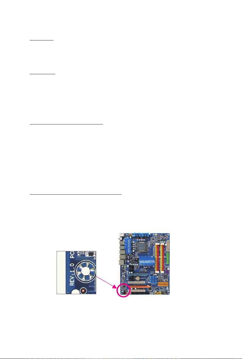
Identifying Your Motherboard Revision
The revision number on your motherboard looks like this: «REV: X.X.» For example, «REV: 1.0»
means the revision of the motherboard is 1.0. Check your motherboard revision before updating
motherboard BIOS, drivers, or when looking for technical information.
Example:

Table of Contents
GA-G41M-Combo Motherboard Layout ………………………………………………………………..5
Chapter 1 Hardware Installation ………………………………………………………………………….6
1-1 Installation Precautions ………………………………………………………………………… 6
1-2 Product Specications ………………………………………………………………………….. 7
1-3 Installing the CPU and CPU Cooler ……………………………………………………….. 9
1-3-1 Installing the CPU ………………………………………………………………………………………..9
1-4 Installing the Memory …………………………………………………………………………. 10
1-4-1 Dual Channel Memory Conguration ……………………………………………………………10
1-5 Installing an Expansion Card ………………………………………………………………. 10
1-6 Back Panel Connectors ………………………………………………………………………. 11
1-7 Internal Connectors ……………………………………………………………………………. 12
Chapter 2 BIOS Setup ……………………………………………………………………………………..21
2-1 Startup Screen ………………………………………………………………………………….. 21
2-2 The Main Menu …………………………………………………………………………………. 21
2-3 MB Intelligent Tweaker(M.I.T.) ……………………………………………………………… 22
2-4 Standard CMOS Features …………………………………………………………………… 28
2-5 Advanced BIOS Features …………………………………………………………………… 29
2-6 Advanced Chipset Features ………………………………………………………………… 31
2-7 Integrated Peripherals ………………………………………………………………………… 32
2-8 Power Management Setup ………………………………………………………………….. 34
2-9 PnP/PCI Congurations ……………………………………………………………………… 36
2-10 PC Health Status ……………………………………………………………………………….. 36
2-11 Load Fail-Safe Defaults ………………………………………………………………………. 37
2-12 Load Optimized Defaults …………………………………………………………………….. 38
2-13 Set Supervisor/User Password ……………………………………………………………. 38
2-14 Save & Exit Setup ……………………………………………………………………………… 39
2-15 Exit Without Saving ……………………………………………………………………………. 39
Chapter 3 Drivers Installation …………………………………………………………………………….40
3-1 Installing Chipset Drivers ……………………………………………………………………. 40
Regulatory Statements ……………………………………………………………………………………..41
— 4 —
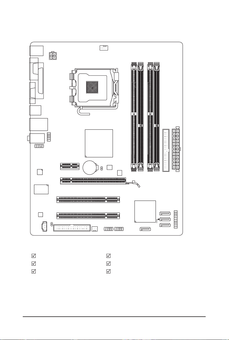
GA-G41M-Combo Motherboard Layout
COMA
VGA
KB_MS
R_USB
USB_LAN
AUDIO
F_AUDIO
Atheros
AR8151
iTE
IT8718F
CODEC
LPT
CD_IN
ATX_12V
COMB
PCIEX1
PCIEX16
PCI1
PCI2
SPDIF_O
FDD
LGA775
Intel® G41
BAT
SYS_FAN
CPU_FAN
B_BIOS
CLR_CMOS
F_USB1
GA-G41M-Combo
DDR2_1
M_BIOS
F_USB2
DDR3_1
Intel® ICH7
SATA2_0
DDR2_2
SATA2_2
IDE
DDR3_2
SATA2_3
SATA2_1
ATX
F_PANEL
Box Contents
GA-G41M-Combo motherboard One IDE cable
Motherboard driver disk Two SATA cables
User’s Manual I/O Shield
The box contents above are for reference only and the actual items shall depend on the product package you obtain.
The box contents are subject to change without notice.
— 5 —

Chapter 1 Hardware Installation
1-1 Installation Precautions
The motherboard contains numerous delicate electronic circuits and components which can
become damaged as a result of electrostatic discharge (ESD). Prior to installation, carefully read
the user’s manual and follow these procedures:
• Prior to installation, do not remove or break motherboard S/N (Serial Number) sticker or
warranty sticker provided by your dealer. These stickers are required for warranty validation.
• Always remove the AC power by unplugging the power cord from the power outlet before
installing or removing the motherboard or other hardware components.
• When connecting hardware components to the internal connectors on the motherboard,
make sure they are connected tightly and securely.
• When handling the motherboard, avoid touching any metal leads or connectors.
• It is best to wear an electrostatic discharge (ESD) wrist strap when handling electronic com-
ponents such as a motherboard, CPU or memory. If you do not have an ESD wrist strap,
keep your hands dry and rst touch a metal object to eliminate static electricity.
• Prior to installing the motherboard, please have it on top of an antistatic pad or within an
electrostatic shielding container.
• Before unplugging the power supply cable from the motherboard, make sure the power sup-
ply has been turned off.
• Before turning on the power, make sure the power supply voltage has been set according to
the local voltage standard.
• Before using the product, please verify that all cables and power connectors of your hard-
ware components are connected.
• To prevent damage to the motherboard, do not allow screws to come in contact with the
motherboard circuit or its components.
• Make sure there are no leftover screws or metal components placed on the motherboard or
within the computer casing.
• Do not place the computer system on an uneven surface
• Do not place the computer system in a high-temperature environment.
• Turning on the computer power during the installation process can lead to damage to sys-
tem components as well as physical harm to the user.
• If you are uncertain about any installation steps or have a problem related to the use of the
product, please consult a certied computer technician.
.
Hardware Installation — 6 —
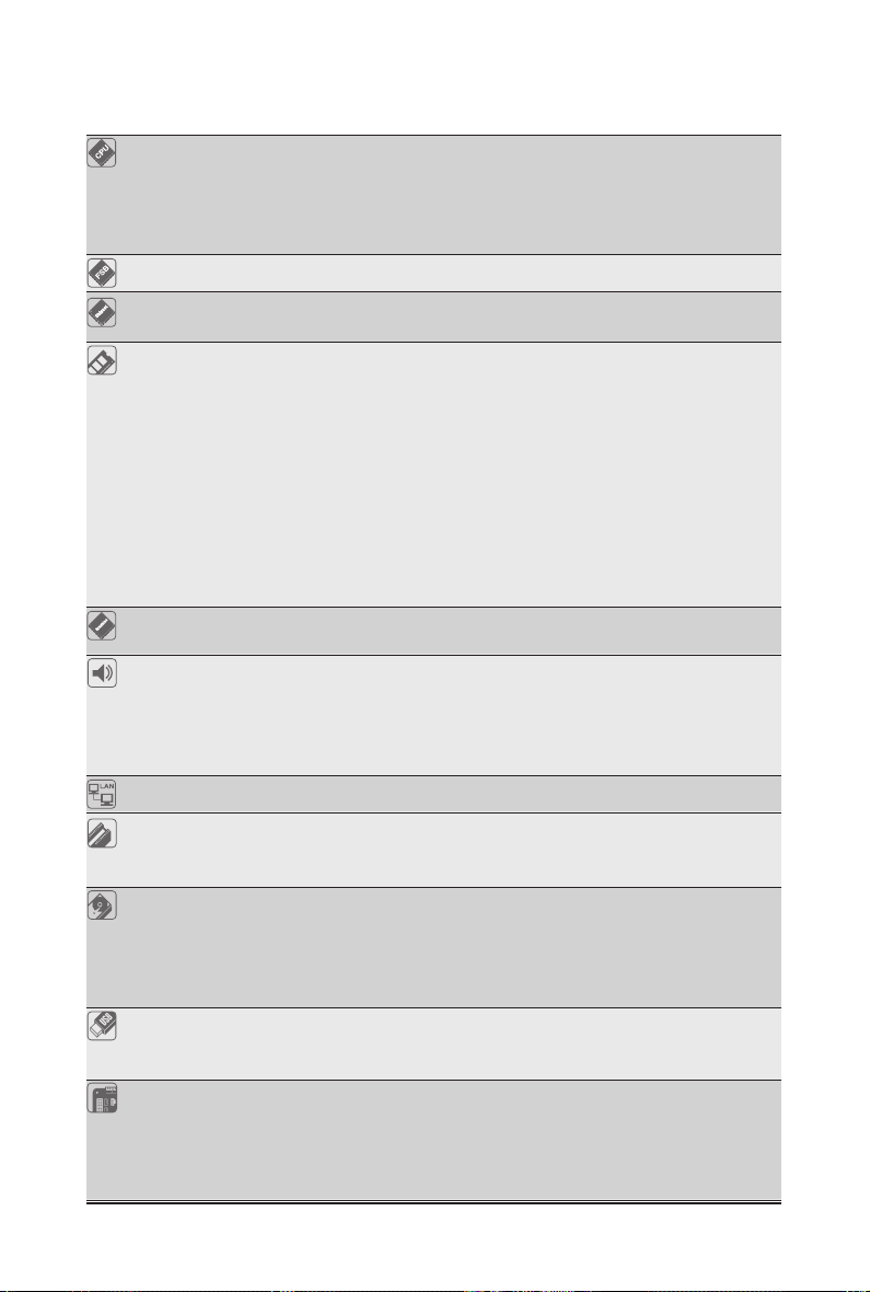
1-2 Product Specications
CPU w Support for an Intel® Core™ 2 Extreme processor/
Intel® Core™ 2 Quad processor/Intel® Core™ 2 Duo processor/
Intel® Pentium® processor/Intel® Celeron® processor in the LGA775 package
(Go to GIGABYTE’s website for the latest CPU support list.)
w L2 cache varies with CPU
Front Side Bus w 1333/1066/800 MHz FSB
Chipset
Memory w DDR3:
— 2 x 1.5V DDR3 DIMM sockets supporting up to 4 GB of system memory
— Support for DDR3 1333(O.C.)/1066/800 MHz memory modules
— 2 x 1.8V DDR2 DIMM sockets supporting up to 8 GB of system memory
— Support for DDR2 1066(O.C.)/800/667 MHz memory modules
(Note: Mixed mode, populating DDR2 and DDR3 memory modules simulta neously is not supported. Go to GIGABYTE’s website for the latest supported
memory speeds and memory modules.)
Onboard Graphics w North Bridge:
— 1 x D-Sub port
Audio
w
wHigh Denition Audio
w2/4/5.1-channel
w
w
w 1 x Atheros AR8151 chip (10/100/1000 Mbit)
LAN
Expansion Slots w 1 x PCI Express x16 slot, running at x16
Storage Interface w South Bridge:
— 1 x IDE connector supporting ATA-100/66/33 and up to 2 IDE devices
— 4 x SATA 3Gb/s connectors supporting up to 4 SATA 3Gb/s devices
w iTE IT8718F chip:
— 1 x oppy disk drive connector supporting up to 1 oppy disk drive
USB w South Bridge:
— Up to 8 USB 2.0/1.1 ports (4 on the back panel, 4 via the USB brackets
connected to the internal USB headers)
Internal w 1 x 24-pin ATX main power connector
Connectors w 1 x 4-pin ATX 12V power connector
w 1 x oppy disk drive connector
w 1 x IDE connector
w 4 x SATA 3Gb/s connectors
North Bridge: Intel® G41 Express Chipset
w
South Bridge: Intel® ICH7
w
— Dual channel memory architecture
DDR2:
w
w
w
— Dual channel memory architecture
VIA VT1708S codec
Support for S/PDIF Out
Support for CD In
1 x PCI Express x1 slot
2 x PCI slots
— 7 — Hardware Installation
(Note 1)
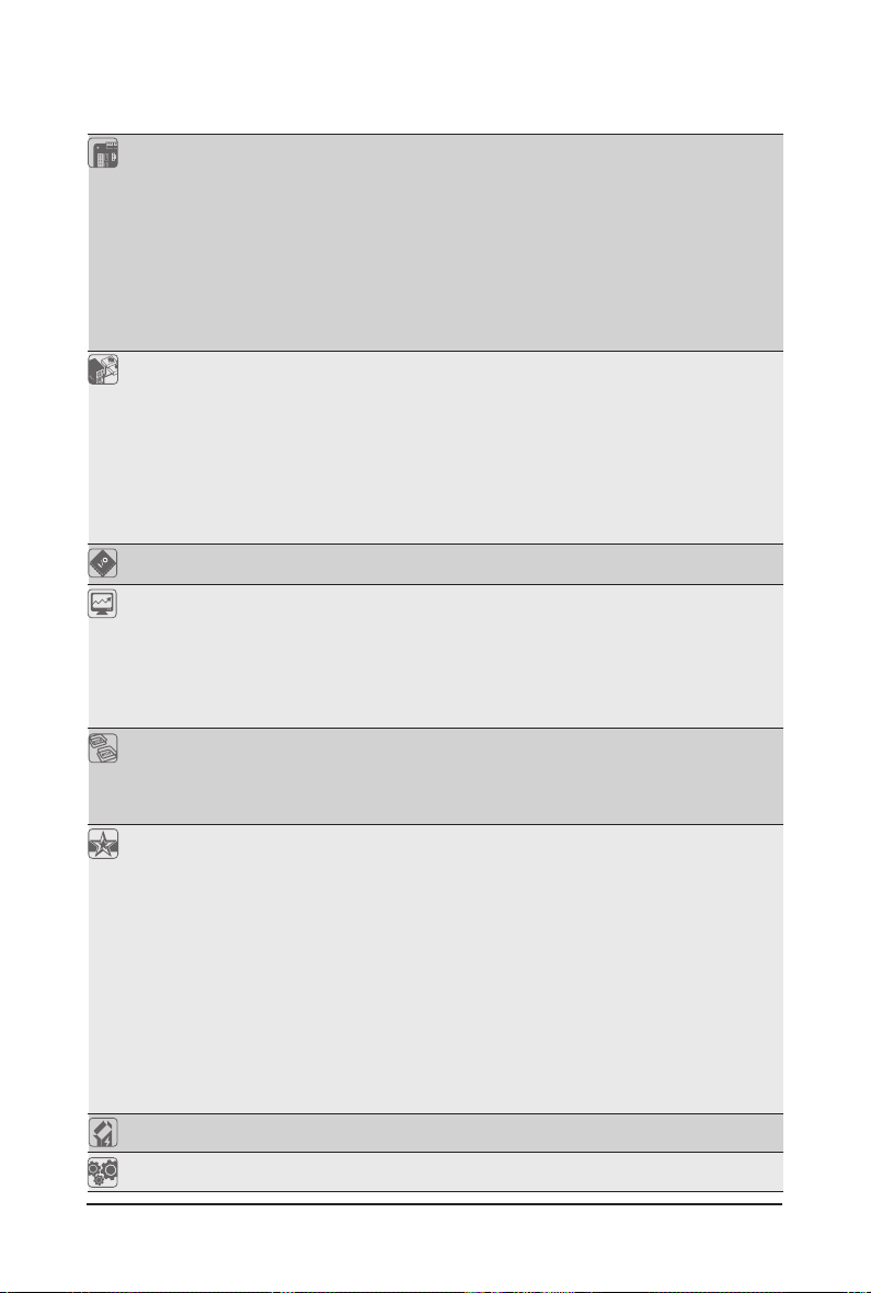
Internal
1 x CPU fan header
w
Connectors w 1 x system fan header
w 1 x front panel header
w 1 x front panel audio header
w 1 x CD In connector
w 1 x S/PDIF Out header
w 2 x USB 2.0/1.1 headers
w 1 x serial port header
w 1 x clearing CMOS jumper
Back Panel w 1 x PS/2 keyboard port
Connectors w 1 x PS/2 mouse port
w 1 x parallel port
w 1 x serial port
w
1 x D-Sub port
w 4 x USB 2.0/1.1 ports
w 1 x RJ-45 port
w 3 x audio jacks (Line In/Line Out/Microphone)
I/O w iTE IT8718F
Hardware Monitor w System voltage detection
w CPU/System temperature detection
w CPU/System fan speed detection
w CPU overheating warning
w CPU/System fan fail warning
w CPU fan speed control
(Note 2)
BIOS w 2 x 8 Mbit ash
w Use of licensed AWARD BIOS
w Support for DualBIOS
™
w PnP 1.0a, DMI 2.0, SM BIOS 2.4, ACPI 1.0b
Unique Features w Support for @BIOS
w Support for Q-Flash
w Support for Xpress BIOS Rescue
w Support for Download Center
w Support for Xpress Install
w Support for Xpress Recovery2
w Support for EasyTune
w Support for Easy Energy Saver
(Note 3)
(Note 4)
w Support for SMART Recovery
w Support for Auto Green
w Support for ON/OFF Charge
w Support for Q-Share
Bundled Software w Norton Internet Security (OEM version)
Operating System w Support for Microsoft® Windows® 7/Vista/XP
Hardware Installation — 8 —
Form Factor w Micro ATX Form Factor; 24.4cm x 21.0cm
(Note 1) Due to Windows 32-bit operating system limitation, when more than 4 GB of physical memory is
installed, the actual memory size displayed will be less than 4 GB.
(Note 2) Whether the CPU fan speed control function is supported will depend on the CPU cooler you install.
(Note 3) Available functions in EasyTune may differ by motherboard model.
(Note 4) Due to the hardware limitation, you must install the Intel®CoreTM 2 Extreme/CoreTM 2 Quad/CoreTM 2 Duo/
Pentium Dual-Core/Celeron Dual-Core/Celeron 400 Series CPU to enable support for Easy Energy Saver.
1-3 Installing the CPU and CPU Cooler
Read the following guidelines before you begin to install the CPU:
• Make sure that the motherboard supports the CPU.
(Go to GIGABYTE’s website for the latest CPU support list.)
• Always turn off the computer and unplug the power cord from the power outlet before installing
the CPU to prevent hardware damage.
• Locate the pin one of the CPU. The CPU cannot be inserted if oriented incorrectly. (Or you may
locate the notches on both sides of the CPU and alignment keys on the CPU socket.)
• Apply an even and thin layer of thermal grease on the surface of the CPU.
• Do not turn on the computer if the CPU cooler is not installed, otherwise overheating and dam-
age of the CPU may occur.
• Set the CPU host frequency in accordance with the CPU specications. It is not recommended
that the system bus frequency be set beyond hardware specications since it does not meet the
standard requirements for the peripherals. If you wish to set the frequency beyond the standard
specications, please do so according to your hardware specications including the CPU, graphics card, memory, hard drive, etc.
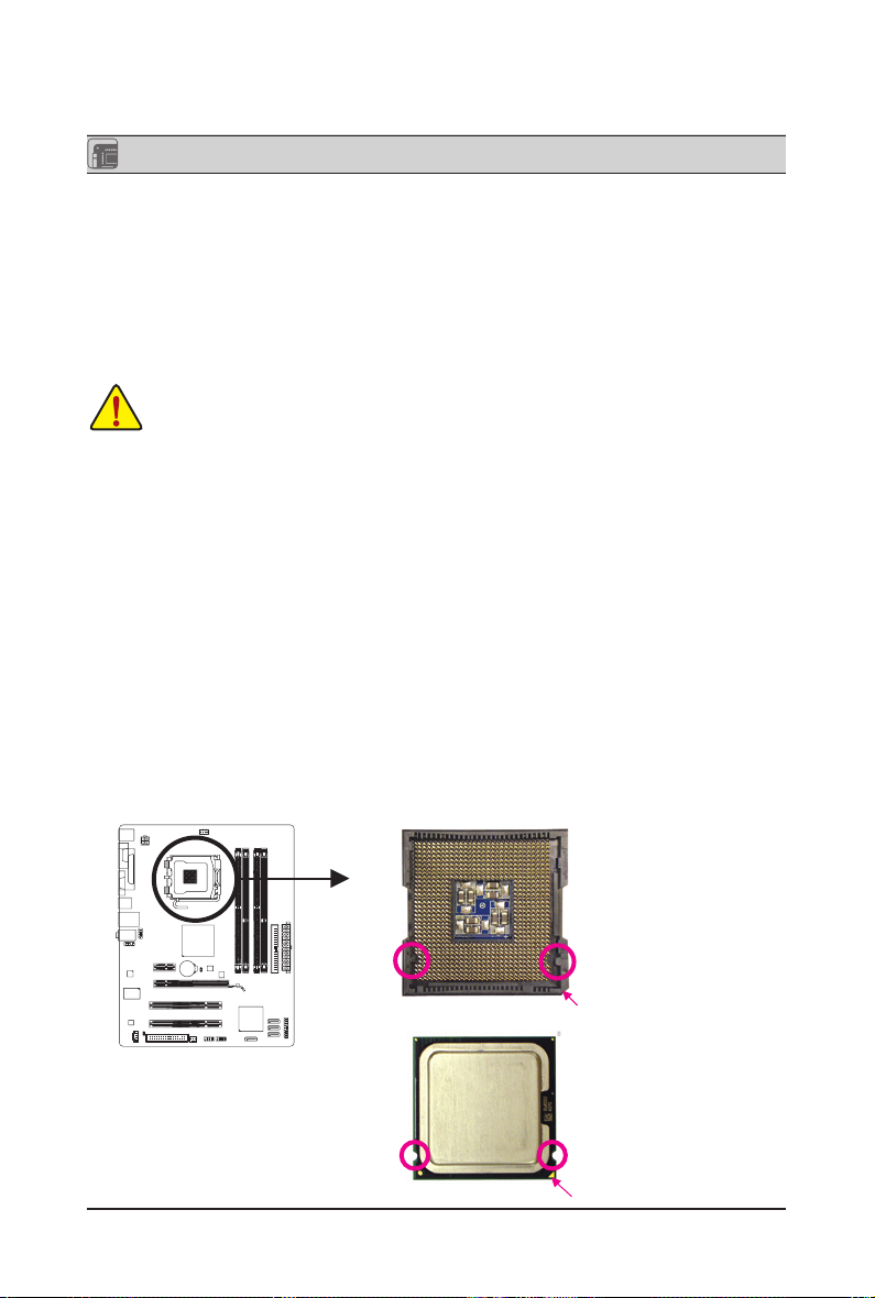
1-3-1 Installing the CPU
Locate the alignment keys on the motherboard CPU socket and the notches on the CPU.
LGA775 CPU Socket
Alignment KeyAlignment Key
Pin One Corner of the CPU Socket
LGA775 CPU
Notch Notch
Triangle Pin One Marking on the CPU
— 9 — Hardware Installation
1-4 Installing the Memory
Read the following guidelines before you begin to install the memory:
• Make sure that the motherboard supports the memory. It is recommended that memory of the
same capacity, brand, speed, and chips be used.
(Go to GIGABYTE’s website for the latest supported memory speeds and memory modules.)
• Always turn off the computer and unplug the power cord from the power outlet before installing
the memory to prevent hardware damage.
• Memory modules have a foolproof design. A memory module can be installed in only one direction. If you are unable to insert the memory, switch the direction.
•
Populating DDR2 and DDR3 memory modules simultaneously is not supported. To ensure memory
compatibility, be sure to use the memory modules on the memory support list at GIGABYTE’s website.
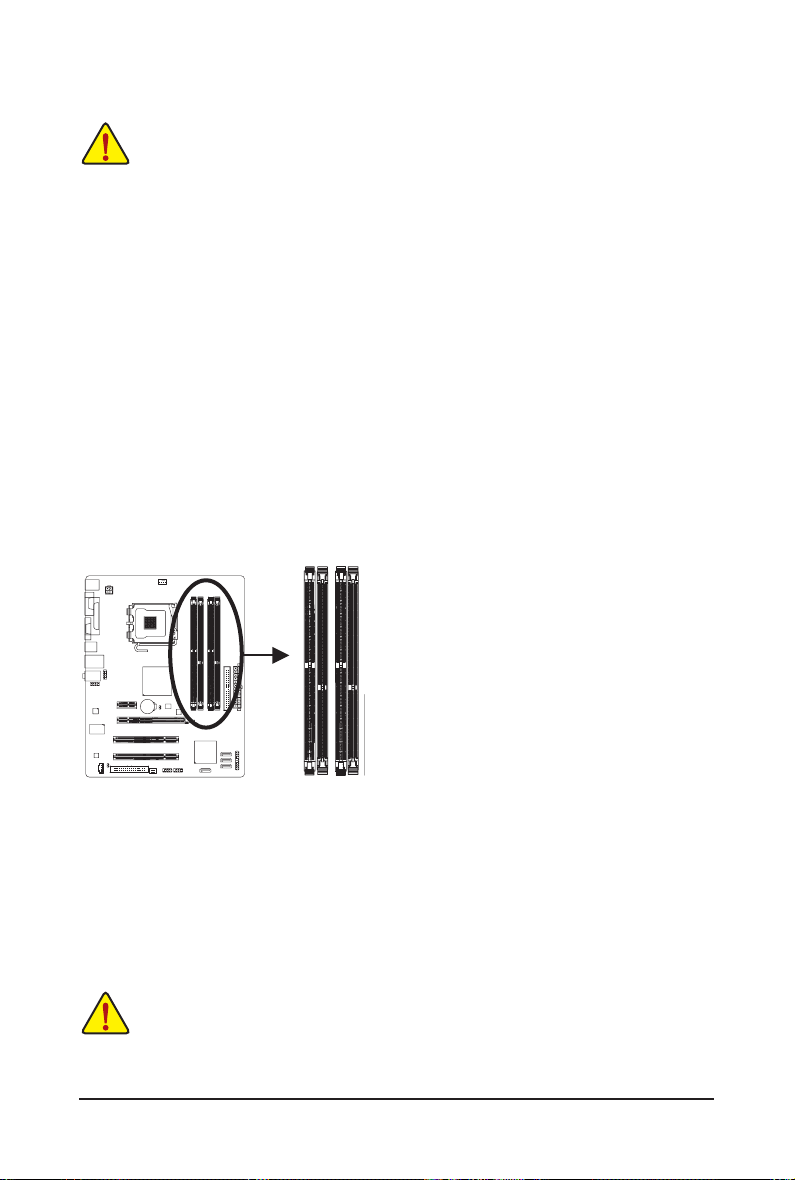
1-4-1 Dual Channel Memory Conguration
This motherboard provides two DDR2 and two DDR3 memory sockets and supports Dual Channel Technology.
The two DDR3 memory sockets (DDR3_1, DDR3_2) are divided into two channels and each channel has one
memory socket as following:
Channel 0: DDR3_1
Channel 1: DDR3_2
The two DDR2 memory sockets (DDR2_1, DDR2_2) are divided into two channels and each channel has one
memory socket as following:
Channel 0: DDR2_1
Channel 1: DDR2_2
DDR2_1
DDR3_1
DDR2_2
DDR3/DDR2 Dual Channel Memory Conguration:
Due to chipset limitations, read the following guidelines before installing the memory in Dual Channel mode.
1. Dual Channel mode cannot be enabled if only one DDR3/DDR2 memory module is installed.
2. When enabling Dual Channel mode with two memory modules, it is recommended that memory of
the same capacity, brand, speed, and chips be used.
DDR3_2
1-5 Installing an Expansion Card
Read the following guidelines before you begin to install an expansion card:
• Make sure the motherboard supports the expansion card. Carefully read the manual that came
with your expansion card.
• Always turn off the computer and unplug the power cord from the power outlet before installing
an expansion card to prevent hardware damage.
Hardware Installation — 10 —
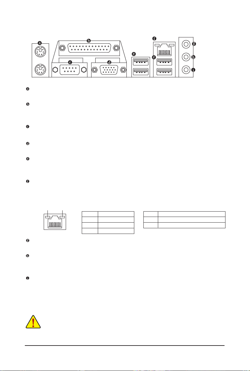
1-6 Back Panel Connectors
PS/2 Keyboard and PS/2 Mouse Port
Use the upper port (green) to connect a PS/2 mouse and the lower port (purple) to connect a PS/2 keyboard.
Parallel Port
Use the parallel port to connect devices such as a printer, scanner and etc. The parallel port is also
called a printer port.
Serial Port
Use the serial port to connect devices such as a mouse, modem or other peripherals.
D-Sub Port
The D-Sub port supports a 15-pin D-Sub connector. Connect a monitor that supports D-Sub connection to this port.
USB 2.0/1.1 Port
The USB port supports the USB 2.0/1.1 specication. Use this port for USB devices such as a USB key-
board/mouse, USB printer, USB ash drive and etc.
RJ-45 LAN Port
The Gigabit Ethernet LAN port provides Internet connection at up to 1 Gbps data rate. The following de-
scribes the states of the LAN port LEDs.
Connection/
Speed LED
Line In Jack (Blue)
The default line in jack. Use this audio jack for line in devices such as an optical drive, walkman, etc.
Line Out Jack (Green)
The default line out jack. Use this audio jack for a headphone or 2-channel speaker. This jack can be
used to connect front speakers in a 4/5.1-channel audio conguration.
Mic In Jack (Pink)
The default Mic in jack. Microphones must be connected to this jack.
LAN Port
Activity LED
Connection/Speed LED:
State Description
Orange 1 Gbps data rate
Green 100 Mbps data rate
Off 10 Mbps data rate
Activity LED:
State Description
Blinking Data transmission or receiving is occurring
Off No data transmission or receiving is occurring
• When removing the cable connected to a back panel connector, rst remove the cable from your
device and then remove it from the motherboard.
• When removing the cable, pull it straight out from the connector. Do not rock it side to side to
prevent an electrical short inside the cable connector.
— 11 — Hardware Installation
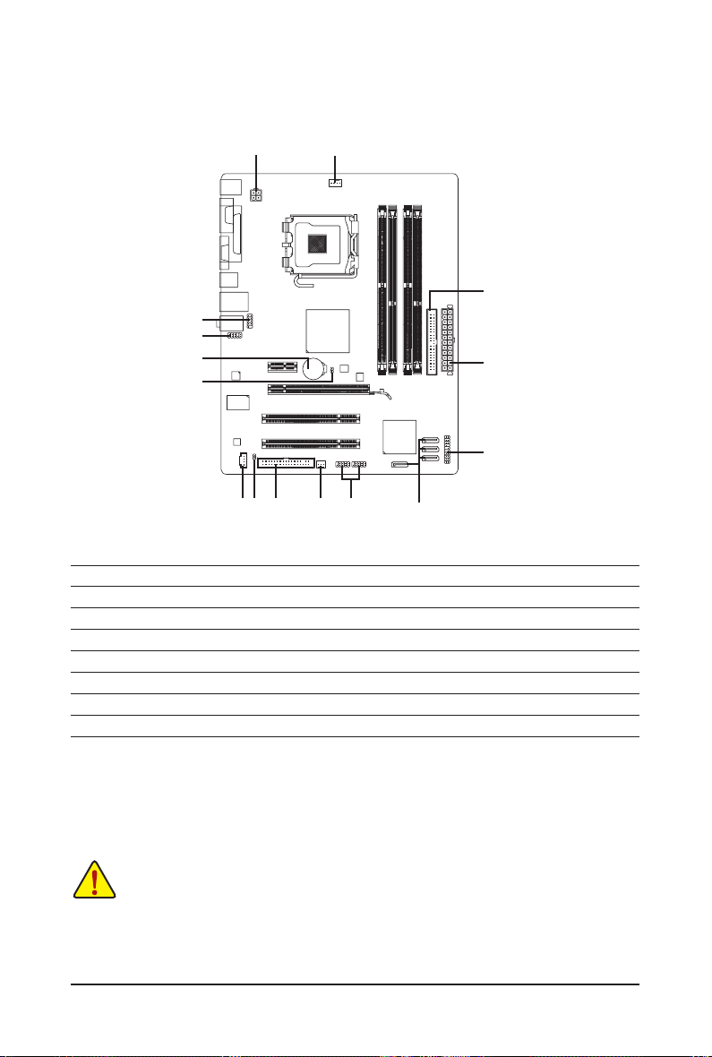
1-7 Internal Connectors
1) ATX_12V
2) ATX
3) CPU_FAN
4) SYS_FAN
5) FDD
6) IDE
7) SATA2_0/1/2/3
 F_PANEL
1
13
9
15
14
511
10
3
6
2
8
12
4
7
9) F_AUDIO
10) CD_IN
11) SPDIF_O
12) F_USB1/F_USB2
13) COMB
14) CLR_CMOS
15) BAT
Read the following guidelines before connecting external devices:
• First make sure your devices are compliant with the connectors you wish to connect.
• Before installing the devices, be sure to turn off the devices and your computer. Unplug the
power cord from the power outlet to prevent damage to the devices.
• After installing the device and before turning on the computer, make sure the device cable has
been securely attached to the connector on the motherboard.
Hardware Installation — 12 —
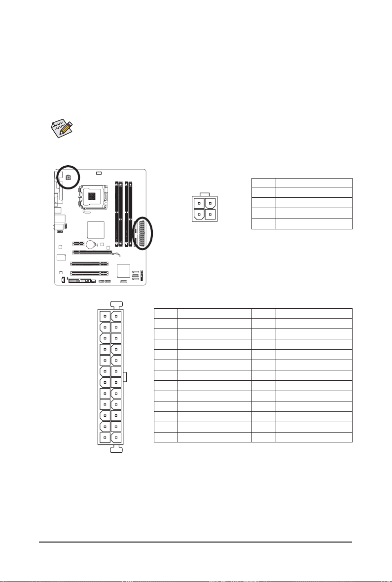
1/2) ATX_12V/ATX (2×2 12V Power Connector and 2×12 Main Power Connector)
With the use of the power connector, the power supply can supply enough stable power to all the com-
ponents on the motherboard. Before connecting the power connector, rst make sure the power supply
is turned off and all devices are properly installed. The power connector possesses a foolproof design.
Connect the power supply cable to the power connector in the correct orientation. The 12V power connector mainly supplies power to the CPU. If the 12V power connector is not connected, the computer will
not start.
To meet expansion requirements, it is recommended that a power supply that can withstand
high power consumption be used (500W or greater). If a power supply is used that does not
provide the required power, the result can lead to an unstable or unbootable system.
ATX_12V:
Pin No. Denition
3
1
4
2
ATX_12V
1 GND
2 GND
3 +12V
4 +12V
ATX
ATX:
2412
131
Pin No. Denition
1 3.3V
2 3.3V
3 GND
4 +5V
5 GND
6 +5V
7 GND
8 Power Good
9 5VSB (stand by +5V)
10 +12V
11 +12V (Only for 2×12-pin ATX)
12 3.3V (Only for 2×12-pin ATX)
Pin No. Denition
13 3.3V
14 -12V
15 GND
16 PS_ON (soft On/Off)
17 GND
18 GND
19 GND
20 -5V
21 +5V
22 +5V
23 +5V (Only for 2×12-pin ATX)
24 GND (Only for 2×12-pin ATX)
— 13 — Hardware Installation
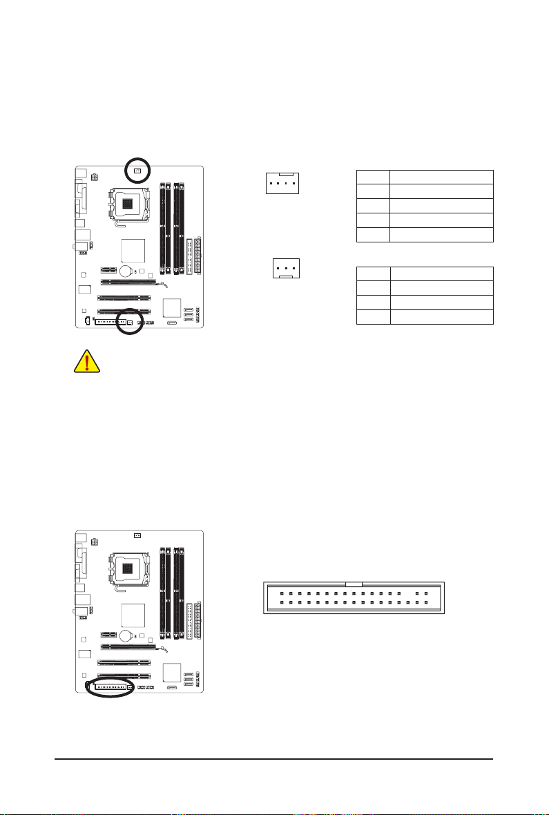
3/4) CPU_FAN/SYS_FAN (Fan Headers)
The motherboard has a 4-pin CPU fan header (CPU_FAN) and a 3-pin (SYS_FAN) system fan header.
Most fan headers possess a foolproof insertion design. When connecting a fan cable, be sure to connect
it in the correct orientation (the black connector wire is the ground wire). The motherboard supports CPU
fan speed control, which requires the use of a CPU fan with fan speed control design. For optimum heat
dissipation, it is recommended that a system fan be installed inside the chassis.
CPU_FAN:
1
CPU_FAN
Pin No. Denition
1 GND
2 +12V
3 Sense
4 Speed Control
1
SYS_FAN
SYS_FAN:
Pin No. Denition
1 GND
2 +12V
3 Sense
• Be sure to connect fan cables to the fan headers to prevent your CPU and system from overheating. Overheating may result in damage to the CPU or the system may hang.
• These fan headers are not conguration jumper blocks. Do not place a jumper cap on the
headers.
5) FDD (Floppy Disk Drive Connector)
This connector is used to connect a oppy disk drive. The types of oppy disk drives supported are:
360 KB, 720 KB, 1.2 MB, 1.44 MB, and 2.88 MB. Before connecting a oppy disk drive, be sure to locate
pin 1 of the connector and the oppy disk drive cable. The pin 1 of the cable is typically designated by
a stripe of different color. For purchasing the optional oppy disk drive cable, please contact the local
dealer.
33
34
1
2
Hardware Installation — 14 —
Loading…
Gigabyte GA-G41M-COMBO Intel G41 Motherboard

Introduction
A motherboard based on the Intel G41 chipset and intended to work with Intel
LGA775 CPUs is the Gigabyte GA-G41M-COMBO. For consumers on a tight budget,
this microATX motherboard offers a number of features like support for
outdated CPUs and DDR2/DDR3 memory modules.
Specifications
- Chipset: Intel G41 Express Chipset
- Socket: LGA775 for Intel Core 2 Extreme/Quad/Duo, Pentium, and Celeron processors
- Memory: Dual-channel DDR3/DDR2 memory architecture; supports up to 8GB of DDR3 1333MHz or up to 4GB of DDR2 800MHz memory
- Graphics: Integrated Intel GMA X4500 graphics with VGA output
- Expansion Slots: 1 x PCIe x16 slot, 1 x PCIe x1 slot, 2 x PCI slots
- Storage: 4 x SATA 3Gb/s connectors, 1 x IDE connector
- Audio: Realtek ALC888 codec with High Definition Audio support
- LAN: Realtek 8111D Gigabit Ethernet controller
- USB: 8 x USB 2.0/1.1 ports (4 on the back panel, 4 via internal USB headers)
- Form Factor: MicroATX
FAQ’s
What processors are compatible with the Gigabyte GA-G41M-COMBO motherboard?
The motherboard supports Intel LGA775 processors, including Core 2 Extreme,
Core 2 Quad, Core 2 Duo, Pentium, and Celeron CPUs.
What type of memory does the motherboard support?
The motherboard supports both DDR3 and DDR2 memory modules with a maximum
capacity of 8GB for DDR3 or 4GB for DDR2.
Does the motherboard have integrated graphics?
Yes, the motherboard features integrated Intel GMA X4500 graphics, which
provides basic graphics capabilities.
How many expansion slots does the motherboard have?
The motherboard has one PCIe x16 slot for a graphics card, one PCIe x1 slot,
and two standard PCI slots for expansion cards.
What kind of storage options are available?
The motherboard supports up to 4 SATA 3Gb/s drives and has one IDE connector
for legacy IDE devices.
What audio capabilities does the motherboard have?
The motherboard features the Realtek ALC888 audio codec, which supports High
Definition Audio for basic audio needs.
Can I use DDR2 and DDR3 memory together?
No, the motherboard supports either DDR2 or DDR3 memory, but they cannot be
used simultaneously.
What is the LAN controller on this motherboard?
The motherboard features the Realtek 8111D Gigabit Ethernet controller for
networking connectivity.
Does the motherboard support USB 3.0?
No, the motherboard only supports USB 2.0 ports.
Can this motherboard run the latest games and software?
The GA-G41M-COMBO is not designed for high-end gaming or resource-intensive
applications due to its older chipset and limited capabilities.
Is this motherboard suitable for building a budget system?
Yes, this motherboard is suitable for budget-conscious users who require basic
computing functionality.
Does the motherboard support Windows 10?
While the motherboard might technically support Windows 10, due to its age and
compatibility limitations, it’s recommended to check Gigabyte’s official
website for information on Windows 10 compatibility and driver availability.
User Manual
References:Gigabyte GA-G41M-COMBO Intel G41 Motherboard –
Device.report
Read User Manual Online (PDF format)
Read User Manual Online (PDF format) >>
Download This Manual (PDF format)
Download this manual >>
-
Драйверы
10
-
Инструкции по эксплуатации
22
Языки:
Gigabyte GA-G41M-Combo инструкция по эксплуатации
(72 страницы)
- Языки:Венгерский, Греческий, Испанский, Итальянский, Немецкий, Польский, Португальский, Русский, Турецкий, Французский, Чешский
-
Тип:
PDF -
Размер:
18.6 MB -
Описание:
Installation Guidebook
На NoDevice можно скачать инструкцию по эксплуатации для Gigabyte GA-G41M-Combo. Руководство пользователя необходимо для ознакомления с правилами установки и эксплуатации Gigabyte GA-G41M-Combo. Инструкции по использованию помогут правильно настроить Gigabyte GA-G41M-Combo, исправить ошибки и выявить неполадки.
-
Page 1
GA-G41M-Combo LGA775 socket motherboard for Intel ® Core ™ processor family/ Intel ® Pentium ® processor family/Intel ® Celeron ® processor family User’s Manual Rev . 1301 12ME-G41MC-1301R[…]
-
Page 2
Motherboard GA-G41M-Combo May 24, 2010 May 24, 2010 Motherboard GA-G41M-Combo[…]
-
Page 3
Copyright © 2010 GIGA-BYTE TECHNOLOGY CO., L TD. All rights reserved. The trademarks mentioned in this manual are legally registered to their respective owners. Disclaimer Information in this manual is protected by copyright laws and is the property of GIGABYTE. Changes to the specications and features in this manual may be made by GIGABYTE wit[…]
-
Page 4
— 4 — T able of Contents Box Contents ……………………………………………………………………………………………………. 6 Optional Items ………………………………………………………………………………………………….. 6 GA-G41M-Combo Motherboard Layout …………………………[…]
-
Page 5
— 5 — Chapter 3 Drivers Installation ……………………………………………………………………………. 55 3-1 Installing Chipset Drivers ……………………………………………………………………. 55 3-2 Application Software ……………………………………………………………………….[…]
-
Page 6
— 6 — Box Contents GA-G41M-Combo motherboard Motherboard driver disk User’s Manual One IDE cable T wo SA T A cables I/O Shield Optional Items Floppy disk drive cable (Part No. 12CF1-1FD001-7*R) 2-port USB 2.0 bracket (Part No. 12CR1-1UB030-5*R) 2-port SA T A power cable (Part No. 12CF1-2SERPW-0*R) S/PDIF In and Out cable (Part No. 12CR1-1SPINO[…]
-
Page 7
— 7 — GA-G41M-Combo Motherboard Layout KB_MS COMA CPU_F AN LGA775 GA-G41M-Combo CD_IN F_AUDIO AUDIO B_BIOS M_BIOS IDE SPDIF_O DDR3_1 DDR3_2 BA T A TX_12V Intel ® G41 Intel ® ICH7 FDD PCIEX16 VGA USB_LAN CLR_CMOS CODEC SYS_F AN COMB F_USB1 F_USB2 F_P ANEL SA TA2_0 SA TA2_1 SA TA2_2 SA TA2_3 Atheros AR8151 R_USB PCI2 PCI1 PCIEX1 LPT iTE IT8718F A T[…]
-
Page 8
— 8 — GA-G41M-Combo Motherboard Block Diagram PS/2 KB/Mouse 8 USB Ports LGA775 CPU Host Interface Intel ® G41 GMCH CLK (333/266/200 MHz) DDR3 1333(O.C.)/1066/800 MHz Intel ® ICH7 PCI Bus Dual Channel Memory PCI CLK (33 MHz) PCIe CLK (100 MHz) PCI Express x16 Floppy CPU CLK+/- (333/266/200 MHz) 4 SA T A 3Gb/s A T A-100/66/33 IDE Channel 1 PCI Expr[…]
-
Page 9
— 9 — Hardware Installation 1- 1 Installation Precautions Th e m ot her bo ar d c on ta in s n um er ou s d el ic at e e le ct ro ni c c ir cu it s a nd comp one nt s w hi ch can become damaged as a result of electrostatic discharge (ESD). Prior to installation, carefully read the user’s manual and follow these procedures: • Prio r to ins[…]
-
Page 10
Hardware Installation — 10 — 1- 2 Product Specications CPU w Support for an Intel ® Core ™ 2 Extreme processor/ Intel ® Core ™ 2 Quad processor/Intel ® Core ™ 2 Duo processor/ Intel ® Pentium ® processor/Intel ® Celeron ® processor in the LGA775 package (Go to GIGABYTE’s website for the latest CPU support list.) w L2 cache vari[…]
-
Page 11
— 1 1 — Hardware Installation Internal w 1 x 24-pin A TX main power connector Connectors w 1 x 4-pin A TX 12V power connector w 1 x oppy disk drive connector w 1 x IDE connector w 4 x SA T A 3Gb/s connectors w 1 x CPU fan header w 1 x system fan header w 1 x front panel header w 1 x front panel audio header w 1 x CD In connector w 1 x S/PDIF Out[…]
-
Page 12
Hardware Installation — 12 — (Note 1) Due to Windows 32-bit operating system limitation, when more than 4 GB of physical memory is installed, the actual memory size displayed will be less than 4 GB. (Note 2) Whether the CPU fan speed control function is supported will depend on the CPU cooler you install. (Note 3) Available functions in EasyTune ma[…]
-
Page 13
— 13 — Hardware Installation 1-3 Installing the CPU and C PU C ooler Read the following guidelines before you begin to install the CPU: • Make sure that the motherboard supports the CPU. (Go to GIGABYTE’s website for the latest CPU support list.) • Always turn off the computer and unplug the power cord from the power outlet before in[…]
-
Page 14
Hardware Installation — 14 — B. Follow the steps below to correctly install the CPU into the motherboard CPU socket. Step 1: Completely raise the CPU socket lever . Step 3: Re m o ve t h e p r ot e c t iv e s o ck e t c o ve r f r o m th e load pla te. (T o protec t the CPU s ocket, always re p l a ce t h e p r o te c t i ve s o c k et co v e r w h[…]
-
Page 15
— 15 — Hardware Installation 1-3 -2 I nst all ing t he CPU Cool er Follow the steps below to correctly install the CPU cooler on the motherboard. (The following procedure uses Intel ® boxed cooler as the example cooler .) Step 1: Apply an even and thin layer of thermal grease on the surface of the installed CPU. Male Pus h Pin Female Push Pin The […]
-
Page 16
Hardware Installation — 16 — DDR3_1 DDR3_2 DDR3/DDR2 Dual Channel Memory Conguration: Due to chipset limitations, read the following guidelines before installing the memory in Dual Channel mode. 1. Dual Channel mode cannot be enabled if only one DDR3/DDR2 memory module is installed. 2. When enabling Dual Channel mode with two memory modules, it […]
-
Page 17
— 17 — Hardware Installation Notch 1- 4 -2 Inst all ing a M emo r y Before installing a memory module, make sure to turn off the computer and unplug the power cord from the power outlet to prevent damage to the memory module. DDR3 and DDR2 DIMMs are not compatible to each other or DDR DIMMs. Do not install DDR DIMMs on this motherboard. Populating […]
-
Page 18
Hardware Installation — 18 — 1-5 Installing an Expansion Card Read the following guidelines before you begin to install an expansion card: • Make sure the motherboard supports the expansion card. Carefully read the manual that came with your expansion card. • Always turn off the computer and unplug the power cord from the power outlet before in[…]
-
Page 19
— 19 — Hardware Installation 1-6 Back Panel Connectors • When removing the cable connected to a back panel connector, rst remove the cable from your device and then remove it from the motherboard. • When removing the cable, pull it straight out from the connector . Do not rock it side to side to prevent an electrical short inside the c[…]
-
Page 20
Hardware Installation — 20 — 1- 7 Internal Connec tors Read the following guidelines before connecting external devices: • First make sure your devices are compliant with the connectors you wish to connect. • Befor e ins tall ing th e dev ices, be sur e to tu rn off th e devi ces a nd you r com puter. Unplu g the power cord from the power[…]
-
Page 21
— 21 — Hardware Installation Pin No. Denition 1 GND 2 GND 3 +12V 4 +12V A TX_12V: DEBUG PO RT G.QBOFM 13 1 24 12 A TX A TX: Pin No. Denition 13 3.3V 14 -12V 15 GND 16 PS_ON (soft On/Off) 17 GND 18 GND 19 GND 20 -5V 21 +5V 22 +5V 23 +5V (O nly for 2×12-pi n A TX) 24 GN D ( Only for 2 x12-p in A TX) Pin No. Denition 1 3.3V 2 3.3V 3 GND 4 +5V[…]
-
Page 22
Hardware Installation — 22 — 3/4) CPU_F AN/SYS_F AN (Fan Headers) The motherboard has a 4-pin CPU fan header (CPU_F AN) and a 3-pin (SYS_F AN) system fan header. Most fan headers possess a foolproof insertion design. When connecting a fan cable, be sure to connect it in the correct orientation (the black connector wire is the ground wire). The moth[…]
-
Page 23
— 23 — Hardware Installation 6) IDE (IDE Connector) The IDE connector supports up to two IDE devices such as hard drives and optical drives. Before attach- ing the IDE cable, locate the foolproof groove on the connector . If you wish to connect two IDE devices, remember to set the jumpers and th e cabling accordi ng to the role o f the IDE devices […]
-
Page 24
Hardware Installation — 24 —
 F_P ANEL (Front Panel Header) Connect the power switch, reset switch, speaker and system status indicator on the chassis front panel to this header according to the pin assignments below . Note the positive and negative pins before con- necting the cables. The fr ont pan el des ign ma y differ by chas sis. A f ront p[…]
 -
Page 25
— 25 — Hardware Installation 9) F_AUDIO (Front Panel Audio Header) The front panel audio header supports Intel High Denition audio (HD) an d AC’97 audi o. Y ou may connect your chassis front panel audio module to this header. Make sure the wire assignments of the module con — nector match the pin assignments of the motherboard header. Incor[…]
-
Page 26
Hardware Installation — 26 — 12) F_USB1/F_USB2 (USB Headers) The headers conform to USB 2.0/1.1 specication. Each USB header can provide two USB ports via an optional USB bracket. For purchasing the optional USB bracket, please contact the local dealer . Pin No. Denition 1 Power (5V) 2 Power (5V) 3 USB DX- 4 USB DY — 5 USB DX+ 6 USB DY+ 7 GND[…]
-
Page 27
— 27 — Hardware Installation 13) COMB (Serial Port Header) The COM header can provide one serial port via an optional COM port cable. For purchasing the op- tional COM port cable, please contact the local dealer . Pin No. Denition 1 NDCD- 2 NSIN 3 NSOUT 4 NDTR- 5 GND 6 NDSR- 7 NRTS- 8 NCTS- 9 NRI- 10 No Pin 14) CLR_CMOS (Clearing CMOS Jumper) Us[…]
-
Page 28
Hardware Installation — 28 — 15) BA T(Battery) The battery provides power to keep the values (such as BIOS congurations, date, and time information) in the CMOS when the computer is turned off. Replace the battery when the battery voltage drops to a low level, or the CMOS values may not be accurate or may be lost. Y ou may clear the CMOS values […]
-
Page 29
— 29 — BIOS Setup BIOS (Ba sic Inpu t and Out put Syst em) reco rds hard ware par ameters of the sy stem in t he CMOS o n the motherboard. Its major functions include conducting the Power-On Self-T est (POST) during system startup, saving sy stem param eters and l oading op erating sy stem, etc . BIOS incl udes a BIO S Setup pro gram that allows th[…]
-
Page 30
BIOS Setup — 30 — 2-1 Startup Screen The following screens may appear when the computer boots. Function Keys: <DEL>: BIOS SETUP Press the <Delete> key to enter BIOS Setup or to access the Q-Flash utility in BIOS Setup. <F9>: XPRESS RECOVERY2 If you have ever entered Xpress Recovery2 to back up hard drive data using the driver disk[…]
-
Page 31
— 31 — BIOS Setup 2-2 The Main Menu Once you enter the BIOS Setup program, the Main Menu (as shown below) appears on the screen. Use ar- row keys to move among the items and press <Enter> to accept or enter a sub-menu. (Sample BIOS V ersion: E20c) Main Menu Help The on-screen description of a highlighted setup option is displayed on the botto[…]
-
Page 32
BIOS Setup — 32 — The Functions of the <F1 1> and <F12> keys (For the Main Menu Only) F1 1: Save CMOS to BIOS This function allows you to save the current BIOS settings to a prole. Y ou can create up to 8 proles (Prole 1-8) and name each prole. First enter the prole name (to erase the default prole name, use[…]
-
Page 33
— 33 — BIOS Setup 2-3 MB Intelligent T weaker(M.I.T .) (Note) This item appears only if you install a CPU that supports this feature. Whether the system will work stably with the overclock/overvoltage settings you made is dependent on your overall system congurations. Incorrectly doing overclock/overvoltage may result in dam — age to CPU, chipse[…]
-
Page 34
BIOS Setup — 34 — Robust Graphics Booster Robust Graphics Booster (R.G.B.) helps to enhance the performance of the graphics chip and memory. Auto allows the BIOS to automatically set the R.G.B. mode based on system congurations. Options are: Auto (default), Fast, Turbo. CPU Clock Ratio (Note) Allows you to alter the clock ratio for the installed[…]
-
Page 35
— 35 — BIOS Setup System Memory Multiplier (SPD) Allows you to set the system memory multiplier. Options are dependent on CPU FSB and the (G)MCH Frequency Latch settings. Auto sets memory multiplier according to memory SPD data. (Default: Auto) Memory Frequency (Mhz) The rst memory f requenc y value i s the nor mal ope rating f requenc y of the […]
-
Page 36
BIOS Setup — 36 — tWR Options are: Auto (default), 1~31. tRFC Options are: Auto (default), 1~255. tRTP Options are: Auto (default), 1~15. Command Rate(CMD) Options are: Auto (default), 1~3. >>>>> Channel A/B Channel A/B T iming Settings CMOS Setup Utility-Copyright (C) 1984-2010 A ward Software Channel A/B Timing Settings higf : Move[…]
-
Page 37
— 37 — BIOS Setup T wr2rd(Different Rank) Options are: Auto (default), 1~15. T rd2wr(Same/Diff Rank) Options are: Auto (default), 1~15. DIMM1 Clock Skew Control Options are: Auto (default), +800ps~-700ps. DIMM2 Clock Skew Control Options are: Auto (default), +800ps~-700ps. DDR Write Leveling Allows you to determine whether to ne-tune memory para[…]
-
Page 38
BIOS Setup — 38 — Ctrl Driving Pull-Up Level Options are: Auto (default), +8~-7. Clk Driving Pull-Up Level Options are: Auto (default), +8~-7. Data Driving Pull-Down Level Options are: Auto (default), +8~-7. Cmd Driving Pull-Down Level Options are: Auto (default), +8~-7. Ctrl Driving Pull-Down Level Options are: Auto (default), +8~-7. Clk Driving P[…]
-
Page 39
— 39 — BIOS Setup Date (mm:dd:yy) Sets the system date. The date format is week (read-only), month, date and year . Select the desired eld and use the up arrow or down arrow key to set the date. Time (hh:mm:ss) Sets the system time. For example, 1 p.m. is 13:0:0. Select the desired eld and use the up arrow or down arrow key to set the time. I[…]
-
Page 40
BIOS Setup — 40 — The following elds display your hard drive specications. If you wish to enter the parameters manually , refer to the information on the hard drive. Capacity Approximate capacity of the currently installed hard drive. Cylinder Number of cylinders. Head Number of heads. Precomp Write precompensation cylinder. Landing Zone Land[…]
-
Page 41
— 41 — BIOS Setup (Note) This item is present only if you install a CPU that supports this feature. For more information about Intel CPUs’ unique features, please visit Intel’s website. 2-5 Advanced BIOS Features Hard Disk Boot Priority Species the sequence of loading the operating system from the installed hard drives. Use the up or d[…]
-
Page 42
BIOS Setup — 42 — CPU Multi-Threading (Note) Allows you to determine whether to enable all CPU cores and multi-threading function when using an Intel CPU that supports multi-core technology . This feature only works for operating systems that support multi-processor mode. Enabled Enables all CPU cores and multi-threading capability . (Default) Disa[…]
-
Page 43
— 43 — BIOS Setup 2-6 Advanced Chipset Features CMOS Setup Utility-Copyright (C) 1984-2010 A ward Software Advanced Chipset Features ** VGA Setting ** Onboard VGA [Enable If No Ext PEG] Init Display First [PCI] P A VP Mode [P A VP Lite Mode] P A VP Lite Mode [32MB] x Paranoid P A VP Mode (32+96)128MB higf : Move Enter: Select +/-/PU/PD: V alue F10:[…]
-
Page 44
BIOS Setup — 44 — P A VP Lite Mode This item is congurable only if the P A VP Mode option is set to P A VP Lite Mode . Options are: 32MB (default), 48MB, 64MB, 128MB and 256MB. Paranoid P A VP Mode This item is congurable only if the P A VP Mode option is set to Paranoid P A VP . Options are: (32+96)128MB (default), (48+96) Round to 160MB, (6[…]
-
Page 45
— 45 — BIOS Setup 2-7 Integrated Peripherals On-Chip Primary PCI IDE Enables or disables the rst integrated IDE controller . (Default: Enabled) On-Chip SA T A Mode Congures the integrated SA T A controller . Disabled Disables the integrated SA T A controller. Auto Lets the BIOS set SA T A devices to Combined or Enhanced mode . If your onboard[…]
-
Page 46
BIOS Setup — 46 — Azalia Codec Enables or disables the onboard audio function. (Default: Auto) If you wish to install a 3rd party add-in audio card instead of using the onboard audio, set this item to Disabled . Onboard H/W LAN Enables or disables the onboard LAN function. (Default: Enabled) If you wish to install a 3rd party add-in network card in[…]
-
Page 47
— 47 — BIOS Setup When a Cable Problem Occurs… If a cable problem occurs on a specied pair of wires, the Status eld will show Short and thenlength shown will be the approximate distance to the fault or short. Example: Part1-2 Status = Short / Length = 2m Explanation: A fault or short might occur at about 2m on Pair 1-2. Onboard LAN Boot ROM[…]
-
Page 48
BIOS Setup — 48 — ACPI Suspend T ype Species the ACPI sleep state when the system enters suspend. S1(POS) Enables the system to enter the ACPI S1 (Power on Suspend) sleep state. In S1 sleep state, the system appears suspended and stays in a low power mode. The system can be resumed at any time. S3(STR) Enables the system to enter the ACPI S3 (Su[…]
-
Page 49
— 49 — BIOS Setup (Note) Supported on Windows 7/Vista operating system only . Resume by Alarm Determines whether to power on the system at a desired time. (Default: Disabled) If enabled, set the date and time as following: Date (of Month) Alarm: Turn on the system at a specic time on each day or on a specic day in a month. Time (hh: mm: ss) A[…]
-
Page 50
BIOS Setup — 50 — PCI1 IRQ Assignment Auto BIOS auto-assigns IRQ to the rst PCI slot. (Default) 3,4,5,7,9,10,1 1,12,14,15 Assigns IRQ 3,4,5,7,9,10,1 1,12,14,15 to the rst PCI slot. PCI2 IRQ Assignment Auto BIOS auto-assigns IRQ to the second PCI slot. (Default) 3,4,5,7,9,10,1 1,12,14,15 Assigns IRQ 3,4,5,7,9,10,1 1,12,14,15 to the second PCI […]
-
Page 51
— 51 — BIOS Setup Reset Case Open Status Keeps or clears the record of previous chassis intrusion status. Enabled clears the record of previous chassis intrusion status and the Case Opened eld will show «No» at next boot. (Default: Disabled) Case Opened Displays the detection status of the chassis intrusion detection device attached to[…]
-
Page 52
BIOS Setup — 52 — Press <Enter> on this item and then press the <Y> key to load the safest BIOS default settings. In case system instability occurs, you may try to load Fail-Safe defaults, which are the safest and most stable BIOS settings for the motherboard. 2-1 1 Load Fail-Safe Defaults CMOS Setup Utility-Copyright (C) 1984-2010 A wa[…]
-
Page 53
— 53 — BIOS Setup Press <Enter> on this item and type the password with up to 8 characters and then press <Enter>. Y ou will be requested to conrm the password. T ype the password again and press <Enter>. The BIOS Setup program allows you to specify two separate passwords: Supervisor Password When a system password is set and t[…]
-
Page 54
BIOS Setup — 54 — Press <Enter> on this item and press the <Y> key . This saves the changes to the CMOS and exits the BIOS Setup program. Press <N> or <Esc> to return to the BIOS Setup Main Menu. 2-14 Save & Exit Setup Press <Enter> on this item and press the <Y> key. This exits the BIOS Setup without saving […]
-
Page 55
— 55 — Drivers Installation 3-1 Installing Chipset Drivers Chapter 3 Drivers Installation • Before installing the drivers, rst install the operating system. • After installing the operating system, insert the motherboard driver disk into your optical drive. The driver Autorun screen is automatically displayed which looks like that show[…]
-
Page 56
Drivers Installation — 56 — 3-2 Application Software This page displays all the utilities and applications that GIGABYTE develops and some free software. Y ou can click the Install button on the right of an item to install it. 3-3 T echnical Manuals This page provides GIGABYTE’s application guides, content descriptions for this driver disk, an[…]
-
Page 57
— 57 — Drivers Installation 3-4 Contact For the detailed contact information of the GIGABYTE T aiwan headquarter or worldwide branch ofces, click the URL on this page to link to the GIGABYTE website. 3-5 System This page provides the basic system information.[…]
-
Page 58
Drivers Installation — 58 — 3-6 Download Center T o update the BIO S, drivers, or applications, click the Download Ce nter button to link to t he GIGABYTE website. The latest version of the BIOS, drivers, or applications will be displayed. 3-7 New Utilities This page provides a quick link to GIGABYTE’s lately developed utilities for users to i[…]
-
Page 59
— 59 — Unique Features 4 — 1 Xpress Recovery 2 Chapter 4 Unique F eatures Xp r es s R e co v er y 2 i s a u ti l it y t h at a l l ow s y ou to q u ic k l y co m p re s s an d back up your system data and perform restoration of it. Supporting NTFS, F A T32, and F A T16 le systems, Xpress Recovery2 can back up data on P A T A and SA T A hard driv[…]
-
Page 60
Unique Features — 60 — Step 3: Wh e n pa r ti t io n in g y o ur h a rd d r i ve , m ak e s ur e t o leave unallocated space (10 GB or more is recom- mended; actual size requirements vary , depending on the amount of data) and begin the installation of the operating system. Step 1: Select BACKUP to start backing up your hard drive data. Step 4: Aft[…]
-
Page 61
— 61 — Unique Features D. Using the Restore Function in Xpress Recovery2 E. Removing the Backup F . Exiting Xpress Recovery2 Sel ec t RESTORE to re st or e th e ba ck up t o yo ur h ar d dr ive in case the system breaks down. The RESTORE option will not be present if no backup is created before. Select REBOOT to exit Xpress Recovery2. Step 2: After[…]
-
Page 62
Unique Features — 62 — 4 -2-1 U pda tin g th e BI OS wi th t he Q — Fl ash Ut ili t y A. Before Y ou Begin 1. From GIGABYTE’s website, download the latest compressed BIOS update le that matches your moth — erboard model. 2. Extract the le and save the new BIOS le (e.g. g41mc.f1) to your oppy disk, USB ash drive, or hard drive. N[…]
-
Page 63
— 63 — Unique Features B. Updating the BIOS When updatin g the BIOS, ch oose the loc ation where t he BIOS le is saved. The followi ng procedure as — sumes that you save the BIOS le to a oppy disk. Step 1: 1. Insert the oppy disk containing the BIOS le into the oppy disk driv e. In the main menu of Q-Flash, use the up or down arro[…]
-
Page 64
Unique Features — 64 — Step 4: Press <Esc> and then <Enter> to exit Q-Flash and reboot the system. As the system boots, you should see the new BIOS version is present on the POST screen. Step 5: During the POST , press <Delete> to enter BIOS Setup. Select Load Optimized Defaults and press <Enter> to load BIOS defaults. Syste[…]
-
Page 65
— 65 — Unique Features 4 -2-2 U pda tin g th e BI OS wi th t he @ BI OS Ut ili t y A. Before Y ou Begin 1. In Windows, close all applications and TSR (T erminate and Stay Resident) programs. This helps prevent unexpected failures when performing a BIOS update. 2. D uring t he BIOS u pdate pr ocess, e nsure th e Inter net conn ection i s stable and […]
-
Page 66
Unique Features — 66 — 4 -3 Easy T une 6 GIGABYTE’s EasyTune 6 is a simple and easy-to-use interface that allows users to ne-tune their system settings or do overclock/overvoltage in Windows environment. The user-friendly EasyTune 6 interface also includes tabbed pages for CPU and memory information, letting users read their system-related […]
-
Page 67
— 67 — Unique Features 4 — 4 Easy Energy Sav er GIGABYTE Easy Energy Saver (Note 1) is a revolutionary technology that delivers unparalleled power savings with a click of the button. Featuring an advanced proprietary software design, GIGABYTE Easy Energy Saver is able to provide exceptional power savings and enhanced power efciency without sacri[…]
-
Page 68
Unique Features — 68 — B. T otal Mode In T otal Mode, users are able to see how much total power savings they have accumulated in a set period of time since activating Easy Energy Saver for the rst time (Note 4) . C. Stealth Mode In Stealth Mode, the system continues t o work with the user-dened power saving settings, even after the system is[…]
-
Page 69
— 69 — Unique Features 4 — 5 Q — Share Q-Share is an easy and convenient data sharing too l. After conguring your LAN connection settings and Q-Share, you are able to share your data with computers on the same network, making full use of Internet resources. Directions for using Q-Share After installing Q-Share from the motherboard driver disk, g[…]
-
Page 70
Unique Features — 70 — 4 — 6 SMART Recovery With SMART Recovery , users can quickly create backups of changed data les (Note 1) or copy les from a spe — cic backup on P A T A and SA T A hard drives (partitioned on NTFS le system) in Windows Vista. Instructions for copying les/folders from a backup: T o b r ow se t hr ou g h yo ur b a[…]
-
Page 71
— 71 — Unique Features 4 -7 Auto Green Auto Green is an easy-to-use tool that provides users with simple options to enable system power savings via a Bluetooth cell phone. When the phone is out of the range of the computer’s Bluetooth receiver , the sys- tem will enter the specied power saving mode. Sele cting a sy stem e nerg y savi ng m o[…]
-
Page 72
Unique Features — 72 -[…]
-
Page 73
— 73 — Appendix 5-1-1 Conguring 2/4/5.1-Channel Audio The motherboard provides three audio jacks on the back panel which support 2/4/5.1 (Note) -channel audio. The picture to the right shows the default audio jack assignments. 5-1 Conguring Audio Input and Output High Denition Audio (HD Audio) HD Audio include s multip le high q uality d i[…]
-
Page 74
Appendix — 74 — Th e pi c tu re s t o th e r ig ht sh ow t h e 2/4/5.1 -c h an ne l speaker congurations. 2-Channel Speakers: Center/Subwoofer Speaker Out Front Speaker Out Rear Speaker Out 4-Channel Speakers: 5.1-Channel Speakers: Front Speaker Out Rear Speaker Out Speakers or Headphones Step 2: Aft er co nn ect ing the s pea ke r(s ), in E xpe[…]
-
Page 75
— 75 — Appendix Step 3: Then, click the Speaker Setting and T est tab. Select the 2 Channels , 4 Channels , or 6 Channels icon according to the type o f spea ker c ong urat ion yo u wis h to se t up. Then the speaker setup is completed. B. Environmental Modeling Y ou may congure an audio environment on the Environmental Modeling tab. If y o u[…]
-
Page 76
Appendix — 76 — 5-1-2 Conguring Microphone Recording Step 1: After installing the audio driver , the VIA HD Audio Deck icon will appear in the notication area. Double-click the icon to access the VIA HD Audio Deck . Step 2: Connect your microphone to the Mic in jack (pink) on th e ba c k pa ne l o r th e M ic i n j ac k ( pi nk ) o n th e f r[…]
-
Page 77
— 77 — Appendix Step 4: T o raise the recording and playback volume for the mi- crophone, click the Automatic recording gain control icon . Set the voice level. Step 5: After co mpletin g the set tings a bove, cl ick Start , p oint to All Programs , point to Accessories , and then click Sound Recorder to begin the sound recording. * Conguring S/[…]
-
Page 78
Appendix — 78 — 5-1-3 Using the Sound Recorder A. Recording Sound 1. Make sure you have connected the sound input device (e.g. microphone) to the computer. 2. T o record the audio, click the Start Recording button . 3. T o stop recording audio, click the Stop Recording button . Be sure to save the recorded audio le upon completion. B. Playing th[…]
-
Page 79
— 79 — Appendix 5-2 T roubleshooting 5-2-1 Frequently Asked Questions T o read more FAQs for your motherboard, please go to the Support&DownloadsMotherboardF AQ page on GIGABYTE’s website. Q: In the BIOS Setup program, why are some BIOS options missing? A: Some advanced options are hidden in the BIOS Setup program. Press <Delete> t[…]
-
Page 80
Appendix — 80 — 5-2-2 T roubleshooting Procedure If you encounter any troubles during system startup, follow the troubleshooting procedure below to solve the problem. ST ART A Turn off the power . Remove all peripherals, connecting cables, and power cord etc. Isolate the short circuit. Secure the CPU cooler on the CPU. Connect the CPU cooler power […]
-
Page 81
— 81 — Appendix If the proce dure above is una ble to solv e your p robl em, c onta ct the place of pur chas e or lo cal dealer for help. Or go to the Support&DownloadsT echnical Service Zone page to submit your question. Our customer service staff will reply you as soon as possible. The power supply , CPU or CPU socket might fail. The keyboar[…]
-
Page 82
Appendix — 82 — 5-3 Regulatory Statements Regulatory Notices This document must not be copied without our written permission, and the conten ts there of must not be imparted to a third party nor be used for any unauthorized purpose. Contravention will be prosecuted. We believe that the information contained herein was accurate in all respects at th[…]
-
Page 83
— 83 — Appendix Finally , we suggest that you practice other environmentally friendly actions by understanding and using the energy-saving features of this product (where applicable), recycling the inner and outer packaging (including shipping containers) this product was delivered in, and by disposing of or recycling used batteries properly . With[…]
-
Page 84
Appendix — 84 -[…]
-
Page 85
— 85 — Appendix[…]
-
Page 86
Appendix — 86 -[…]
-
Page 87
— 87 — Appendix Contact Us • GIGA-BYTE TECHNOLOGY CO., L TD. Address: No.6, Bau Chiang Road, Hsin-Tien, T aipei 231, T aiwan TEL: +886-2-8912-4000 F AX: +886-2-8912-4003 T ech. and Non-T ech. Support (Sales/Marketing) : http://ggts.gigabyte.com.tw WEB address (English): http://www .gigabyte.com.tw WEB address (Chinese): http://www .gigabyte.tw ?[…]
-
Page 88
Appendix — 88 — • G.B.T . TECHNOLOGY TRADING GMBH — Germany WEB address : http://www .gigabyte.de • G.B.T . TECH. CO., L TD. — U.K. WEB address : http://www .giga-byte.co.uk • Giga-Byte T echnology B.V . — The Netherlands WEB address : http://www .giga-byte.nl • GIGABYTE TECHNOLOGY FRANCE — France WEB address : http://www .gigabyte.fr • S[…]