

For more product details, please visit GIGABYTE’s website.
To reduce the impacts on global warming, the packaging materials of this product
are recyclable and reusable. GIGABYTE works with you to protect the environment.
H410M H V2
User’s Manual
Rev. 1001
Copyright
© 2021 GIGA-BYTE TECHNOLOGY CO., LTD. All rights reserved.
The trademarks mentioned in this manual are legally registered to their respective owners.
Disclaimer
Information in this manual is protected by copyright laws and is the property of GIGABYTE.
Changes to the specications and features in this manual may be made by GIGABYTE without
prior notice. No part of this manual may be reproduced, copied, translated, transmitted, or
published in any form or by any means without GIGABYTE’s prior written permission.
In order to assist in the use of this product, carefully read the User’s Manual.
For product-related information, check on our website at: https://www.gigabyte.com
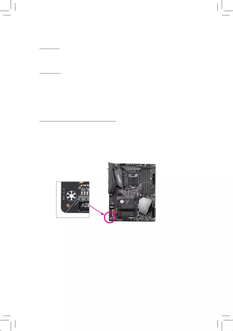
Identifying Your Motherboard Revision
The revision number on your motherboard looks like this: «REV: X.X.» For example, «REV:
1.0″ means the revision of the motherboard is 1.0. Check your motherboard revision before
updating motherboard BIOS, drivers, or when looking for technical information.
Example:

— 3 —
Table of Contents
H410M H V2 Motherboard Layout ……………………………………………………………………….. 4
Chapter 1 Hardware Installation ………………………………………………………………………….5
1-1 Installation Precautions ………………………………………………………………………… 5
1-2 ProductSpecications ………………………………………………………………………….. 6
1-3 Installing the CPU ……………………………………………………………………………….. 9
1-4 Installing the Memory …………………………………………………………………………… 9
1-5 Installing an Expansion Card ………………………………………………………………. 10
1-6 Back Panel Connectors ………………………………………………………………………. 10
1-7 Internal Connectors ……………………………………………………………………………. 12
Chapter 2 BIOS Setup ……………………………………………………………………………………..19
2-1 Startup Screen ………………………………………………………………………………….. 19
2-2 The Main Menu …………………………………………………………………………………. 20
2-3 Favorites (F11) ………………………………………………………………………………….. 21
2-4 Tweaker ……………………………………………………………………………………………. 22
2-5 Settings ……………………………………………………………………………………………. 27
2-6 System Info. ……………………………………………………………………………………… 32
2-7 Boot …………………………………………………………………………………………………. 33
2-8 Save & Exit ……………………………………………………………………………………….. 36
Chapter 3 Appendix …………………………………………………………………………………………37
3-1 ConguringaRAIDSet ………………………………………………………………………. 37
3-2 Installing an Intel® Optane™ Memory …………………………………………………….. 39
3-3 DriversInstallation ……………………………………………………………………………… 41
RegulatoryNotices ………………………………………………………………………………………. 42
Contact Us …………………………………………………………………………………………………. 43
— 4 —
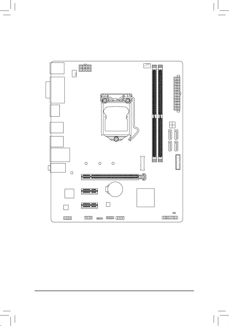
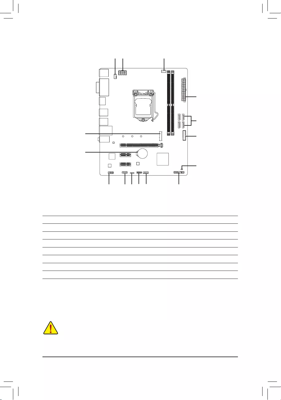
H410M H V2 Motherboard Layout
* The box contents above are for reference only and the actual items shall depend on the product package you obtain.
The box contents are subject to change without notice.
Box Contents
5H410M H V2 motherboard
5Motherboard driver disc 5Two SATA cables
5User’s Manual 5I/O Shield
KB_MS CPU_FAN
SYS_FAN
LGA1200
ATX
H410M H V2
F_AUDIO
COMA LED_C
AUDIO
BAT
ATX_12V_2X4
Intel® H470
U32
CODEC
CLR_CMOS
M_BIOS
VGA
HDMI
USB_LAN
PCIEX16
80 60 42
PCIEX1_1
PCIEX1_2
iTE®
Super I/O
Intel®
GbELAN
F_USB
F_PANEL
SPI_TPM
F_U32
DDR4_B1
DDR4_A1
M2A_SB
3 2
5 4
SATA3
USB20

Chapter 1 Hardware Installation
1-1 Installation Precautions
The motherboard contains numerous delicate electronic circuits and components which can become
damagedasaresultofelectrostaticdischarge(ESD).Priortoinstallation,carefullyreadtheuser’s
manual and follow these procedures:
•Prior to installation, make sure the chassis is suitable for the motherboard.
•Priortoinstallation,donotremoveorbreakmotherboardS/N(SerialNumber)stickeror
warranty sticker provided by your dealer. These stickers are required for warranty validation.
•Always remove the AC power by unplugging the power cord from the power outlet before
installing or removing the motherboard or other hardware components.
•When connecting hardware components to the internal connectors on the motherboard, make
sure they are connected tightly and securely.
•When handling the motherboard, avoid touching any metal leads or connectors.
•It is best to wear an electrostatic discharge (ESD) wrist strap when handling electronic
componentssuchasamotherboard,CPUormemory.IfyoudonothaveanESDwriststrap,
keepyourhandsdryandrsttouchametalobjecttoeliminatestaticelectricity.
•Prior to installing the motherboard, please have it on top of an antistatic pad or within an
electrostatic shielding container.
•Before connecting or unplugging the power supply cable from the motherboard, make sure
the power supply has been turned off.
•Before turning on the power, make sure the power supply voltage has been set according to
the local voltage standard.
•Before using the product, please verify that all cables and power connectors of your hardware
components are connected.
•To prevent damage to the motherboard, do not allow screws to come in contact with the
motherboard circuit or its components.
•Make sure there are no leftover screws or metal components placed on the motherboard or
within the computer casing.
•Donotplacethecomputersystemonanunevensurface.
•Donotplacethecomputersysteminahigh-temperatureorwetenvironment.
•Turning on the computer power during the installation process can lead to damage to system
components as well as physical harm to the user.
•If you are uncertain about any installation steps or have a problem related to the use of the
product,pleaseconsultacertiedcomputertechnician.
•If you use an adapter, extension power cable, or power strip, ensure to consult with its installation
and/or grounding instructions.
— 5 —
1-2 ProductSpecications
CPU Support for 10th Generation Intel® Core™ i9 processors/Intel® Core™ i7 processors/
Intel® Core™ i5 processors/Intel® Core™ i3 processors/Intel® Pentium® processors/
Intel® Celeron® processors in the LGA1200 package
(Go to GIGABYTE’s website for the latest CPU support list.)
L3 cache varies with CPU
Chipset Intel® H470 Express Chipset
Memory Intel® Core™ i9/i7 processors:
- SupportforDDR42933/2666/2400/2133MHzmemorymodules
Intel® Core™ i5/i3/Pentium®/Celeron® processors:
- SupportforDDR42666/2400/2133MHzmemorymodules
2xDDR4DIMMsocketssupportingupto64GB(32GBsingleDIMMcapacity)
of system memory
Dualchannelmemoryarchitecture
SupportforECCUn-bufferedDIMM1Rx8/2Rx8memorymodules (operatein
non-ECC mode)
Supportfornon-ECCUn-bufferedDIMM1Rx8/2Rx8/1Rx16memorymodules
SupportforExtremeMemoryProle(XMP)memorymodules
(Go to GIGABYTE’s website for the latest supported memory speeds and memory
modules.)
Onboard
Graphics
Integrated Graphics Processor-Intel®HDGraphicssupport:
- 1xD-Subport,supportingamaximumresolutionof1920×1200@60Hz
- 1xHDMIport,supportingamaximumresolutionof4096×2160@30Hz
* SupportforHDMI1.4versionandHDCP2.3.
Maximum shared memory of 512 MB
Audio Realtek®AudioCODEC
HighDenitionAudio
2/4/5.1/7.1-channel
* Tocongure7.1-channelaudio,youneedtoopentheaudiosoftwareandselect
Deviceadvanced settings> PlaybackDevice tochange thedefault settingrst.
PleasevisitGIGABYTE’swebsitefordetailsonconguringtheaudiosoftware.
LAN Intel®GbELANchip(1Gbit/100Mbit)
Expansion Slots 1 x PCI Express x16 slot, running at x16
2 x PCI Express x1 slots
(The PCI Express slots conform to PCI Express 3.0 standard.)
Storage Interface 1 x M.2 connector (Socket 3, M key, type 2242/2260/2280 SATA and PCIe x4/
x2SSDsupport)
4 x SATA 6Gb/s connectors
SupportforRAID0,RAID1,RAID5,andRAID10
Intel® Optane™MemoryReady
— 6 —

USB Chipset:
— 4 x USB 3.2 Gen 1 ports (2 ports on the back panel, 2 ports available through
the internal USB header)
— 6 x USB 2.0/1.1 ports (4 ports on the back panel, 2 ports available through
the internal USB header)
Internal
Connectors
1 x 24-pin ATX main power connector
1 x 8-pin ATX 12V power connector
4 x SATA 6Gb/s connectors
1 x CPU fan header
1 x system fan header
1xRGBLEDstripheader
1 x front panel header
1 x front panel audio header
1 x USB 3.2 Gen 1 header
1 x USB 2.0/1.1 header
1 x Trusted Platform Module header (For the GC-TPM2.0 SPI/GC-TPM2.0 SPI
2.0 module only)
1 x serial port header
1 x Clear CMOS jumper
Back Panel
Connectors
1 x PS/2 keyboard port
1 x PS/2 mouse port
1xD-Subport
1xHDMIport
2 x USB 3.2 Gen 1 ports
4 x USB 2.0/1.1 ports
1xRJ-45port
3 x audio jacks
I/O Controller iTE® I/O Controller Chip
Hardware
Monitor
Voltage detection
Temperature detection
Fan speed detection
Overheating warning
Fan fail warning
Fan speed control
* Whether the fan speed control function is supported will depend on the cooler you
install.
BIOS 1x256Mbitash
Use of licensed AMI UEFI BIOS
PnP1.0a,DMI2.7,WfM2.0,SMBIOS2.7,ACPI5.0
— 7 —
Unique Features Support for APP Center
* Available applications in APP Center may vary by motherboard model. Supported
functionsofeachapplicationmayalsovarydependingonmotherboardspecications.
- @BIOS
- AmbientLED
— EasyTune
— Fast Boot
— Game Boost
- ON/OFFCharge
— Smart Backup
— System Information Viewer
Support for Q-Flash
Support for Xpress Install
Bundled
Software
Norton® Internet Security (OEM version)
cFosSpeed
Operating
System Support for Windows 10 64-bit
Form Factor Micro ATX Form Factor; 22.6cm x 18.5cm
* GIGABYTEreservestherighttomakeanychangestotheproductspecicationsandproduct-relatedinformationwithout
prior notice.
— 8 —
Please visit GIGABYTE’s website
for support lists of CPU, memory
modules,SSDs,andM.2devices.
Please visit the Support\Utility List
page on GIGABYTE’s website to
download the latest version of apps.
1-3 Installing the CPU
Please visit GIGABYTE’s website for details on hardware installation.
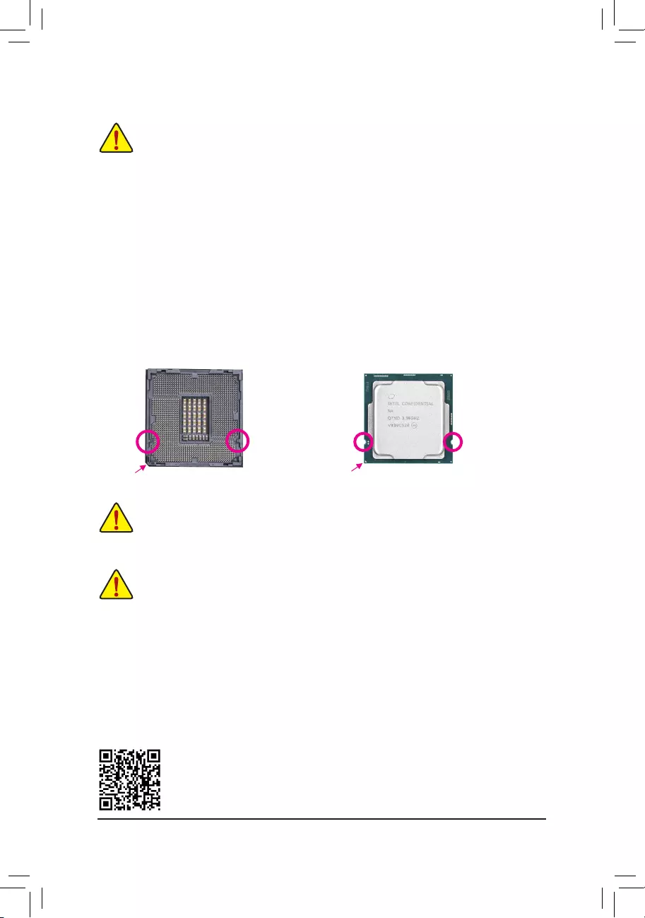
Installing the CPU
Locate the alignment keys on the motherboard CPU socket and the notches on the CPU.
Do not remove the CPU socket cover before inserting the CPU. It may pop off from the load
plate automatically during the process of re—engaging the lever after you insert the CPU.
Triangle Pin One Marking on the CPU
NotchNotch
LGA1200 CPU
Alignment
Key
Alignment
Key
LGA1200 CPU Socket
Pin One Corner of the CPU Socket
ReadthefollowingguidelinesbeforeyoubegintoinstalltheCPU:
•Make sure that the motherboard supports the CPU.
(Go to GIGABYTE’s website for the latest CPU support list.)
•Always turn off the computer and unplug the power cord from the power outlet before installing the
CPU to prevent hardware damage.
•Locate the pin one of the CPU. The CPU cannot be inserted if oriented incorrectly. (Or you may
locate the notches on both sides of the CPU and alignment keys on the CPU socket.)
•Apply an even and thin layer of thermal grease on the surface of the CPU.
•DonotturnonthecomputeriftheCPUcoolerisnotinstalled,otherwiseoverheatinganddamage
of the CPU may occur.
•SettheCPUhostfrequencyinaccordancewiththeCPUspecications.Itisnotrecommended
thatthesystembusfrequencybesetbeyondhardwarespecicationssinceitdoesnotmeetthe
standard requirements for the peripherals. If you wish to set the frequency beyond the standard
specications,pleasedosoaccordingtoyourhardwarespecicationsincludingtheCPU,graphics
card, memory, hard drive, etc.
1-4 Installing the Memory
Readthefollowingguidelinesbeforeyoubegintoinstallthememory:
•Make sure that the motherboard supports the memory. It is recommended that memory of the same
capacity, brand, speed, and chips be used.
(Go to GIGABYTE’s website for the latest supported memory speeds and memory modules.)
•Always turn off the computer and unplug the power cord from the power outlet before installing the
memory to prevent hardware damage.
•Memory modules have a foolproof design. A memory module can be installed in only one direction.
If you are unable to insert the memory, switch the direction.
DualChannelMemoryConguration
ThismotherboardprovidestwomemorysocketsandsupportsDualChannelTechnology.Afterthememory
isinstalled,theBIOSwillautomaticallydetectthespecicationsandcapacityofthememory.EnablingDual
Channel memory mode will double the original memory bandwidth.
— 9 —
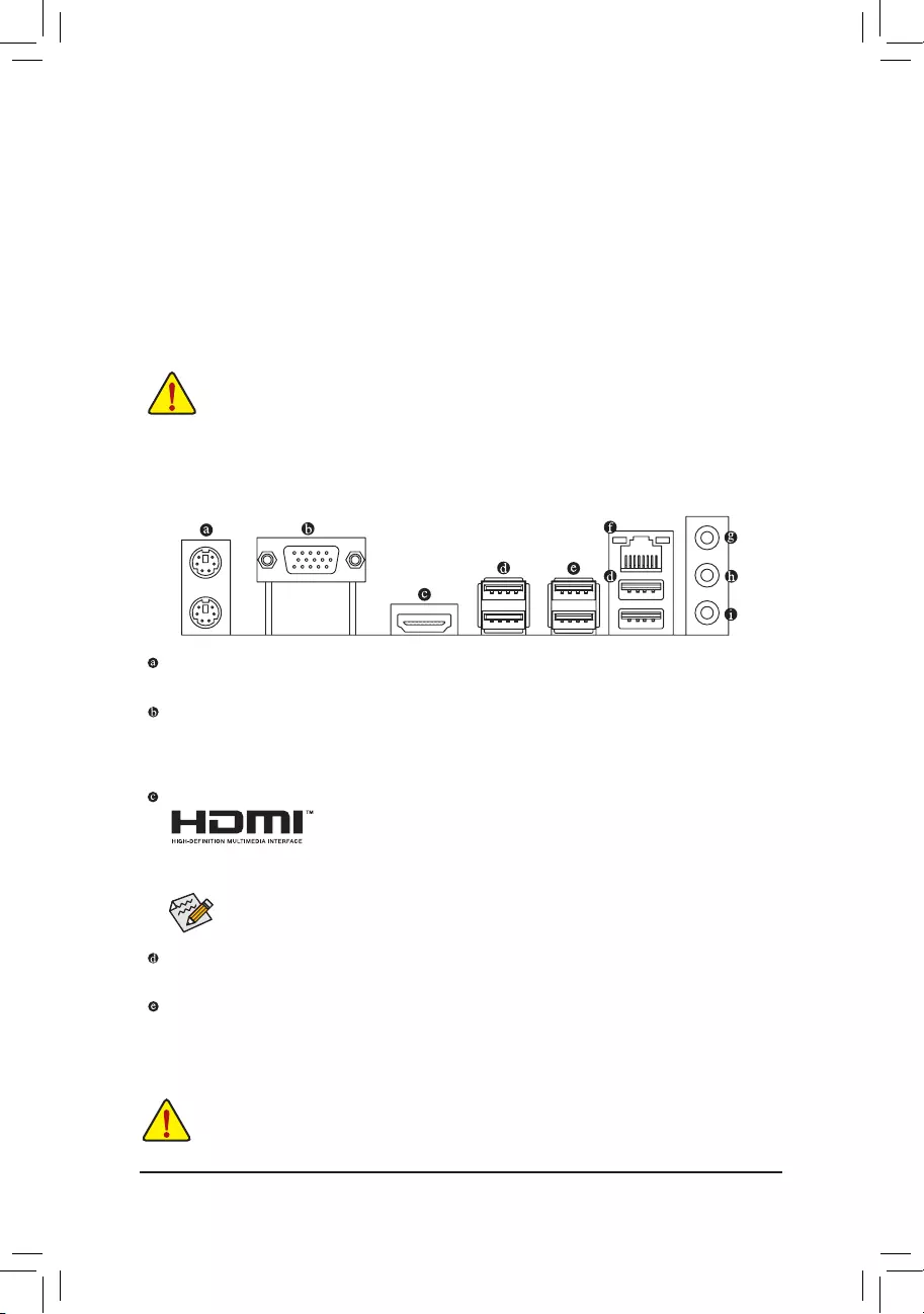
1-6 Back Panel Connectors
PS/2 Keyboard and PS/2 Mouse Port
Use the upper port (green) to connect a PS/2 mouse and the lower port (purple) to connect a PS/2 keyboard.
D-Sub Port
TheD-Subportsupportsa15-pinD-Subconnectorandsupportsamaximumresolutionof1920×1200@60Hz
(the actual resolutions supported depend on the monitor being used). Connect a monitor that supports
D-Subconnectiontothisport.
HDMI Port
TheHDMIportsupportsHDCP2.3andDolbyTrueHDandDTSHDMasterAudio
formats.Italsosupportsupto192KHz/16bit7.1-channelLPCMaudiooutput.
YoucanusethisporttoconnectyourHDMI-supportedmonitor.Themaximumsupportedresolutionis
4096×2160@30Hz,buttheactualresolutionssupportedaredependentonthemonitorbeingused.
AfterinstallingtheHDMIdevice,makesuretosetthedefaultsoundplaybackdevicetoHDMI.
(The item name may differ depending on your operating system.)
1-5 Installing an Expansion Card
Readthefollowingguidelinesbeforeyoubegintoinstallanexpansioncard:
•Make sure the motherboard supports the expansion card. Carefully read the manual that came
with your expansion card.
•Always turn off the computer and unplug the power cord from the power outlet before installing an
expansion card to prevent hardware damage.
DuetoCPUlimitations,readthefollowingguidelinesbeforeinstallingthememoryinDualChannelmode.
1. DualChannelmodecannotbeenabledifonlyonememorymoduleisinstalled.
2. WhenenablingDualChannelmodewithtwomemorymodules,itisrecommendedthatmemoryof
the same capacity, brand, speed, and chips be used.
ThetwoDDR4memorysocketsaredividedintotwochannelsandeachchannelhasonememorysocketas
following:
ChannelA:DDR4_A1
ChannelB:DDR4_B1
•Whenremovingthecableconnectedtoabackpanelconnector,rstremovethecablefromyour
device and then remove it from the motherboard.
•Whenremovingthecable,pullitstraightoutfromtheconnector.Donotrockitsidetosideto
prevent an electrical short inside the cable connector.
USB 2.0/1.1 Port
TheUSBportsupportstheUSB2.0/1.1specication.UsethisportforUSBdevices.
USB 3.2 Gen 1 Port
TheUSB3.2Gen1portsupportstheUSB3.2Gen1specicationandiscompatibletotheUSB2.0
specication.UsethisportforUSBdevices.
— 10 —
AudioJackCongurations:
Jack Headphone/
2-channel 4-channel 5.1-channel 7.1-channel
LineIn/RearSpeakerOut aaa
Line Out/Front Speaker Out aaaa
Mic In/Center/Subwoofer Speaker Out a a
Front Panel Line Out/Side Speaker Out a
PleasevisitGIGABYTE’swebsitefordetailsonconguringtheaudiosoftware.
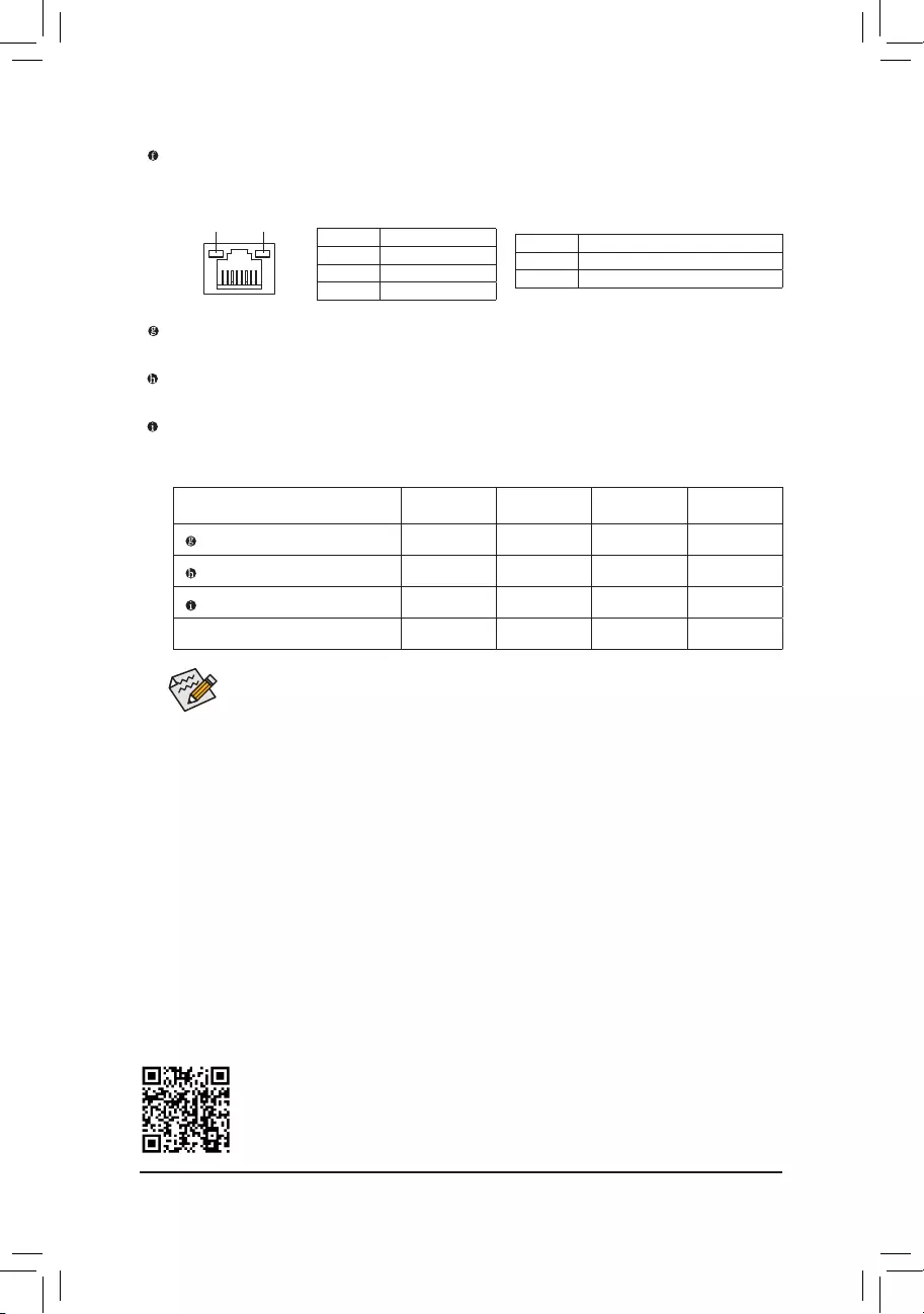
ActivityLED
Connection/
SpeedLED
LANPort
ActivityLED:
Connection/SpeedLED:
State Description
Orange 1 Gbps data rate
Green 100 Mbps data rate
Off 10 Mbps data rate
State Description
Blinking Datatransmissionorreceivingisoccurring
On Nodatatransmissionorreceivingisoccurring
RJ-45 LAN Port
TheGigabitEthernetLANportprovidesInternetconnection at up to 1 Gbpsdatarate.The following
describesthestatesoftheLANportLEDs.
•You can change the functionality of an audio jack using the audio software.
•Tocongure 7.1-channelaudio, you need to open the audio software and select Device
advancedsettings>PlaybackDevicetochangethedefaultsettingrst.
Line In/Rear Speaker Out (Blue)
The line in jack. Use this audio jack for line in devices such as an optical drive, walkman, etc.
Line Out/Front Speaker Out (Green)
The line out jack.
Mic In/Center/Subwoofer Speaker Out (Pink)
The Mic in jack.
— 11 —
1-7 Internal Connectors
Readthefollowingguidelinesbeforeconnectingexternaldevices:
•First make sure your devices are compliant with the connectors you wish to connect.
•Before installing the devices, be sure to turn off the devices and your computer. Unplug the power
cord from the power outlet to prevent damage to the devices.
•After installing the device and before turning on the computer, make sure the device cable has
been securely attached to the connector on the motherboard.
4 1 3
2
10
14
11
15
85
9
6
1312
1) ATX_12V_2X4
2) ATX
3) CPU_FAN
4) SYS_FAN
5) LED_C
6) SATA3 2/3/4/5
7) M2A_SB
 F_PANEL
9) F_AUDIO
10) F_U32
11) F_USB
12) COMA
13) SPI_TPM
14) CLR_CMOS
15) BAT
7
— 12 —
131
24
12
ATX
To meet expansion requirements, it is recommended that a power supply that can withstand high
power consumption be used (500W or greater). If a power supply is used that does not provide the
required power, the result can lead to an unstable or unbootable system.
ATX:
PinNo. Denition PinNo. Denition
1 3.3V 13 3.3V
2 3.3V 14 -12V
3GND 15 GND
4 +5V 16 PS_ON(softOn/Off)
5GND 17 GND
6 +5V 18 GND
7GND 19 GND
8 Power Good 20 NC
9 5VSB (stand by +5V) 21 +5V
10 +12V 22 +5V
11 +12V (Only for 2×12-pin
ATX)
23 +5V (Only for 2×12-pin ATX)
12 3.3V (Only for 2×12-pin
ATX)
24 GND(Onlyfor2×12-pinATX)
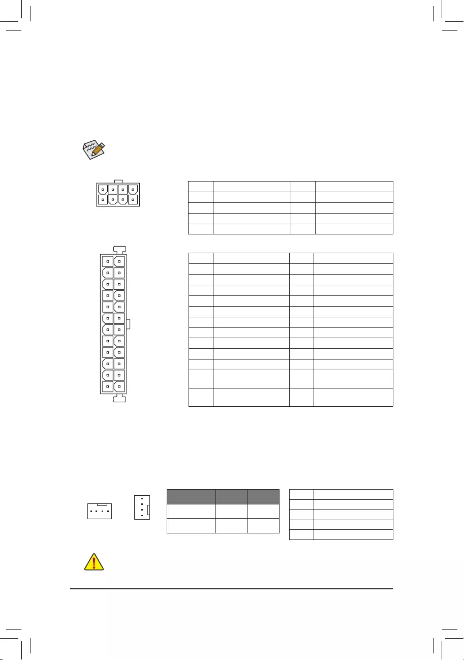
1/2) ATX_12V_2X4/ATX (2×4 12V Power Connector and 2×12 Main Power Connector)
With the use of the power connector, the power supply can supply enough stable power to all the components
onthemotherboard.Beforeconnectingthepowerconnector,rstmakesurethepowersupplyisturned
off and all devices are properly installed. The power connector possesses a foolproof design. Connect the
power supply cable to the power connector in the correct orientation.
The 12V power connector mainly supplies power to the CPU. If the 12V power connector is not connected,
the computer will not start.
ATX_12V_2X4:
PinNo. Denition PinNo. Denition
1GND(Onlyfor2×4-pin12V) 5+12V (Only for 2×4-pin 12V)
2GND(Onlyfor2×4-pin12V) 6+12V (Only for 2×4-pin 12V)
3GND 7 +12V
4GND 8 +12V
ATX_12V_2X4
41
85
3/4) CPU_FAN/SYS_FAN (Fan Headers)
All fan headers on this motherboard are 4-pin. Most fan headers possess a foolproof insertion design.
When connecting a fan cable, be sure to connect it in the correct orientation (the black connector wire is
the ground wire). The speed control function requires the use of a fan with fan speed control design. For
optimum heat dissipation, it is recommended that a system fan be installed inside the chassis.
•Be sure to connect fan cables to the fan headers to prevent your CPU and system from
overheating. Overheating may result in damage to the CPU or the system may hang.
•Thesefanheadersarenotcongurationjumperblocks.Donotplaceajumpercapontheheaders.
CPU_FAN
1
SYS_FAN
PinNo. Denition
1GND
2 Voltage Speed Control
3 Sense
4 PWM Speed Control
1
Connector CPU_FAN SYS_FAN
Maximum Current 2A 2A
Maximum Power 24W 24W
— 13 —
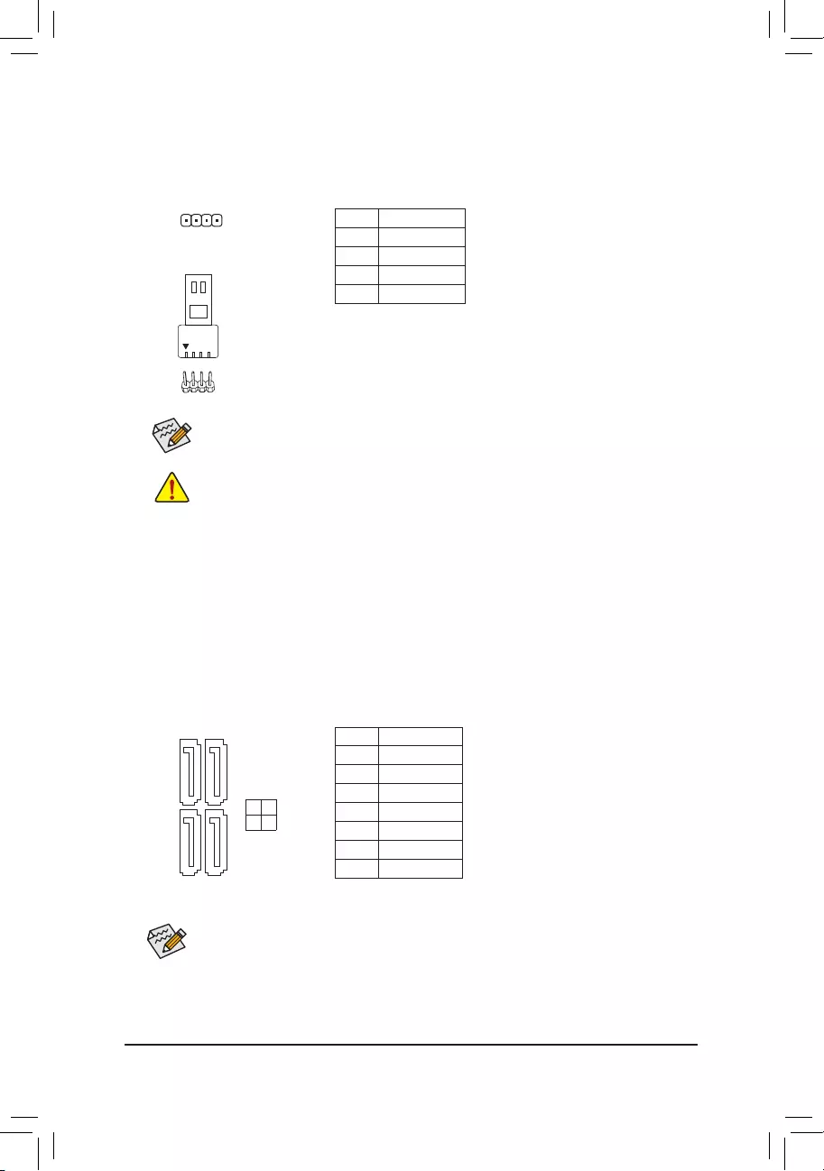
6) SATA3 2/3/4/5 (SATA 6Gb/s Connectors)
The SATA connectors conform to SATA 6Gb/s standard and are compatible with SATA 3Gb/s and SATA
1.5Gb/s standard. Each SATA connector supports a single SATA device. The Intel® ChipsetsupportsRAID0,
RAID1,RAID5,andRAID10.RefertoChapter3,»ConguringaRAIDSet,»forinstructionsonconguring
aRAIDarray.
PinNo. Denition
1GND
2 TXP
3TXN
4GND
5RXN
6RXP
7GND
SATA3
3 2
5 4
77
11
5) LED_C (RGB LED Strip Header)
Theheadercanbeusedtoconnectastandard5050RGBLEDstrip(12V/G/R/B),withmaximumpower
rating of 2A (12V) and maximum length of 2m.
PinNo. Denition
1 12V
2 G
3R
4 B
Before installing the devices, be sure to turn off the devices and your computer. Unplug the power
cord from the power outlet to prevent damage to the devices.
ConnectyourRGBLEDstriptotheheader.Thepowerpin(marked
withatriangleontheplug)oftheLEDstripmustbeconnectedtoPin
1 (12V) of this header. Incorrect connection may lead to the damage
oftheLEDstrip.
Forhowtoturnon/offthelightsoftheLEDstrippleasevisitthe«UniqueFeatures»webpageof
GIGABYTE’s website.
1
RGBLEDStrip
1
12V
Toenablehot-pluggingfortheSATAports,refertoChapter2,«BIOSSetup,»«Settings\IOPorts\
SATAAndRSTConguration,»formoreinformation.
— 14 —
7) M2A_SB (M.2 Socket 3 Connector)
TheM.2connectorsupportsM.2SATASSDsandM.2PCIeSSDs.
F_USB30 F_U
B_
F_ F_
_
B
BS_
B
SB_
B
_S
S_
_
B
_U
_
B
S
123
123
123
123
1
1
1
1
BSS
S
_S
SSU
1 2 3
S3 BSSS
U
__ 3
F_USB3F
S _
S _
S _
SF
B_
B_
F
_0
S
S
_0F
_F
_
_
__B
U
S _S
_ SF_
B
USB0_B
B_
B_
F_USB3
F_USB303
_
_3U
S_
80 60 42
FollowthestepsbelowtocorrectlyinstallanM.2SSDintheM.2connector.
Step 1:
LocatethepropermountingholefortheM.2SSDtobeinstalledandtheninstallthemountingcliprst.
Step 2:
SlidetheM.2SSDintotheconnectoratanangle.
Step 3:
PresstheM.2SSDdownandthensecureitbypressingtheclippinintothemountinghole.
The front panel design may differ by chassis. A front panel module mainly consists of power switch,
resetswitch,powerLED,harddriveactivityLED,speakerandetc.Whenconnectingyourchassis
front panel module to this header, make sure the wire assignments and the pin assignments are
matched correctly.
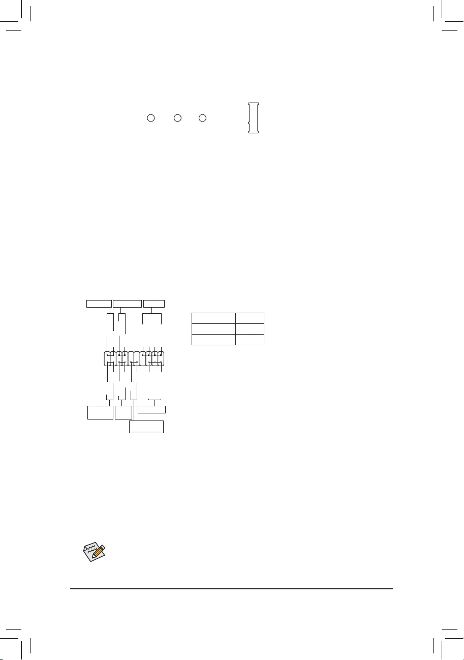
F_PANEL (Front Panel Header)
Connect the power switch, reset switch, speaker, chassis intrusion switch/sensor and system status indicator
onthechassistothisheaderaccordingtothepinassignmentsbelow.Notethepositiveandnegativepins
before connecting the cables.
System Status LED
S0 On
S3/S4/S5 Off
•PW (Power Switch):
Connects to the power switch on the chassis front panel. You may
congure the way to turn off your system using thepower switch
(refertoChapter2,«BIOSSetup,»«Settings\PlatformPower,»formore
information).
•SPEAK (Speaker):
Connects to the speaker on the chassis front panel. The system reports
system startup status by issuing a beep code. One single short beep
will be heard if no problem is detected at system startup.
•PLED/PWR_LED (PowerLED):
Connects to the power status indicator
onthechassisfrontpanel.TheLEDison
whenthesystemisoperating.TheLEDis
off when the system is in S3/S4 sleep state
or powered off (S5).
•HD (HardDriveActivityLED):
ConnectstotheharddriveactivityLEDonthechassisfrontpanel.TheLEDisonwhentheharddrive
is reading or writing data.
•RES (ResetSwitch):
Connects to the reset switch on the chassis front panel. Press the reset switch to restart the computer
ifthecomputerfreezesandfailstoperformanormalrestart.
•CI (Chassis Intrusion Header):
Connects to the chassis intrusion switch/sensor on the chassis that can detect if the chassis cover has
been removed. This function requires a chassis with a chassis intrusion switch/sensor.
•NC: Noconnection.
PLED-
PW-
SPEAK+
SPEAK-
PLED+
PW+
HD-
RES+
HD+
RES-
HardDrive
ActivityLED
Reset
Switch
PowerLED
1
2
19
20
CI-
CI+
PowerLED
Chassis Intrusion
Header
Power Switch Speaker
NC
NC
PWR_LED-
PWR_LED-
PWR_LED+
— 15 —
1
2
9
10
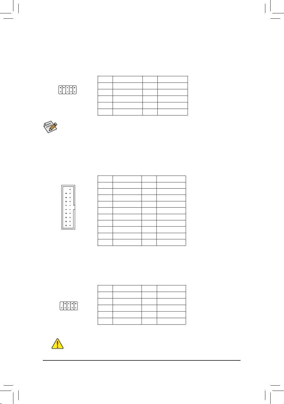
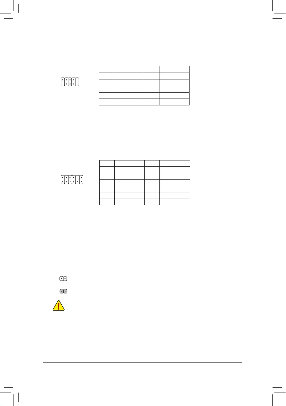
9) F_AUDIO (Front Panel Audio Header)
ThefrontpanelaudioheadersupportsHighDenitionaudio(HD).Youmayconnectyourchassisfront
panel audio module to this header. Make sure the wire assignments of the module connector match the
pin assignments of the motherboard header. Incorrect connection between the module connector and the
motherboard header will make the device unable to work or even damage it.
Some chassis provide a front panel audio module that has separated connectors on each wire instead
of a single plug. For information about connecting the front panel audio module that has different wire
assignments, please contact the chassis manufacturer.
PinNo. Denition PinNo. Denition
1 MIC2_L 6 Sense
2GND 7FAUDIO_JD
3MIC2_R 8NoPin
4NC 9LINE2_L
5LINE2_R 10 Sense
PinNo. Denition PinNo. Denition
1 VBUS 11 D2+
2SSRX1- 12 D2-
3SSRX1+ 13 GND
4GND 14 SSTX2+
5 SSTX1- 15 SSTX2-
6 SSTX1+ 16 GND
7GND 17 SSRX2+
8D1- 18 SSRX2-
9D1+ 19 VBUS
10 NC 20 NoPin
10) F_U32 (USB 3.2 Gen 1 Header)
TheheaderconformstoUSB3.2Gen1andUSB2.0specicationandcanprovidetwoUSBports.For
purchasingtheoptional3.5″frontpanelthatprovidestwoUSB3.2Gen1ports,pleasecontactthelocal
dealer.
F_USB30 F_U
B_
F_ F_
_
B
BS_
B
SB_
B
_S
S_
_
B
_U
_
B
S
123
123
123
123
1
1
1
1
BSS
S
_S
SSU
1 2 3
S3 BSSS
U
__ 3
F_USB3F
S _
S _
S _
SF
B_
B_
F
_0
S
S
_0F
_F
_
_
__B
U
S _S
_ SF_
B
USB0_B
B_
B_
F_USB3
F_USB303
_
_3U
S_
10
20 1
11
11) F_USB (USB 2.0/1.1 Header)
TheheaderconformstoUSB2.0/1.1specication.EachUSBheadercanprovidetwoUSBportsviaan
optional USB bracket. For purchasing the optional USB bracket, please contact the local dealer.
PinNo. Denition PinNo. Denition
1 Power (5V) 6 USBDY+
2 Power (5V) 7 GND
3USBDX- 8GND
4USBDY— 9NoPin
5USBDX+ 10 NC
•DonotplugtheIEEE1394bracket(2×5-pin)cableintotheUSB2.0/1.1header.
•Prior to installing the USB bracket, be sure to turn off your computer and unplug the power cord
from the power outlet to prevent damage to the USB bracket.
10
9
2
1
— 16 —
10
9
2
1
12) COMA (Serial Port Header)
The COM header can provide one serial port via an optional COM port cable. For purchasing the optional
COM port cable, please contact the local dealer.
PinNo. Denition PinNo. Denition
1NDCD- 6NDSR-
2NSIN 7NRTS-
3NSOUT 8NCTS-
4NDTR- 9NRI-
5GND 10 NoPin
12
11
2
1
13) SPI_TPM (Trusted Platform Module Header)
You may connect an SPI TPM (Trusted Platform Module) to this header.
PinNo. Denition PinNo. Denition
1DataOutput 7Chip Select
2Power (3.3V) 8GND
3NoPin 9IRQ
4NC 10 NC
5DataInput 11 NC
6CLK 12 RST
F_USB30 F_U
B_
F_ F_
_
B
BS_
B
SB_
B
_S
S_
_
B
_U
_
B
S
123
123
123
123
1
1
1
1
BSS
S
_S
SSU
1 2 3
S3 BSSS
U
__ 3
F_USB3F
S _
S _
S _
SF
B_
B_
F
_0
S
S
_0F
_F
_
_
__B
U
S _S
_ SF_
B
USB0_B
B_
B_
F_USB3
F_USB303
_
_3U
S_
14) CLR_CMOS (Clear CMOS Jumper)
UsethisjumpertocleartheBIOScongurationandresettheCMOSvaluestofactorydefaults.Toclear
the CMOS values, use a metal object like a screwdriver to touch the two pins for a few seconds.
•Always turn off your computer and unplug the power cord from the power outlet before clearing
the CMOS values.
•Aftersystemrestart,gotoBIOSSetuptoloadfactorydefaults(selectLoadOptimizedDefaults)or
manuallyconguretheBIOSsettings(refertoChapter2,«BIOSSetup,»forBIOScongurations).
Open:Normal
Short: Clear CMOS Values
— 17 —

15) BAT (Battery)
Thebatteryprovidespowertokeepthevalues(suchasBIOScongurations,date,andtimeinformation)
intheCMOSwhenthecomputeristurnedoff.Replacethebatterywhenthebatteryvoltagedropstoalow
level, or the CMOS values may not be accurate or may be lost.
You may clear the CMOS values by removing the battery:
1. Turn off your computer and unplug the power cord.
2. Gently remove the battery from the battery holder and wait for one minute. (Or use a
metal object like a screwdriver to touch the positive and negative terminals of the battery
holder, making them short for 5 seconds.)
3. Replacethebattery.
4. Plug in the power cord and restart your computer.
•Always turn off your computer and unplug the power cord before replacing the battery.
•Replacethebatterywithanequivalentone.Damagetoyourdevicesmayoccurifthebatteryis
replaced with an incorrect model.
•Contact the place of purchase or local dealer if you are not able to replace the battery by yourself
or uncertain about the battery model.
•When installing the battery, note the orientation of the positive side (+) and the negative side (-)
of the battery (the positive side should face up).
•Used batteries must be handled in accordance with local environmental regulations.
— 18 —
BIOS (Basic Input and Output System) records hardware parameters of the system in the CMOS on the
motherboard. Its major functions include conducting the Power-On Self-Test (POST) during system startup,
saving system parameters and loading operating system, etc. BIOS includes a BIOS Setup program that allows
theusertomodifybasicsystemcongurationsettingsortoactivatecertainsystemfeatures.
When the power is turned off, the battery on the motherboard supplies the necessary power to the CMOS to
keepthecongurationvaluesintheCMOS.
ToaccesstheBIOSSetupprogram,pressthe<Delete>keyduringthePOSTwhenthepoweristurnedon.
ToupgradetheBIOS,useeithertheGIGABYTEQ-Flashor@BIOSutility.
•Q-Flash allows the user to quickly and easily upgrade or back up BIOS without entering the operating system.
•@BIOSisaWindows-basedutilitythatsearchesanddownloadsthelatestversionofBIOSfromtheInternet
and updates the BIOS.
Chapter 2 BIOS Setup
•BecauseBIOSashingispotentiallyrisky,ifyoudonotencounterproblemsusingthecurrent
versionofBIOS,itisrecommendedthatyounotashtheBIOS.ToashtheBIOS,doitwith
caution.InadequateBIOSashingmayresultinsystemmalfunction.
•It is recommended that you not alter the default settings (unless you need to) to prevent system
instability or other unexpected results. Inadequately altering the settings may result in system’s
failure to boot. If this occurs, try to clear the CMOS values and reset the board to default values.
(Refertothe«LoadOptimizedDefaults»sectioninthischapterorintroductionsofthebattery/clear
CMOS jumper in Chapter 1 for how to clear the CMOS values.)
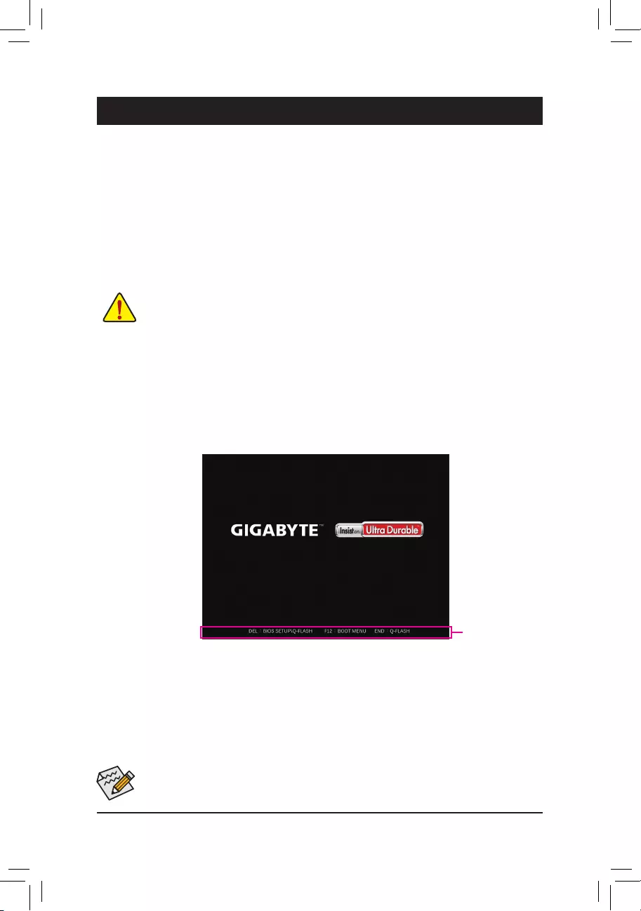
2-1 Startup Screen
The following startup Logo screen will appear when the computer boots.
Function Keys
•When the system is not stable as usual, select the Load Optimized Defaults item to set your system to its defaults.
•The BIOS Setup menus described in this chapter are for reference only and may differ by BIOS version.
TherearetwodifferentBIOSmodesasfollowsandyoucanusethe<F2>keytoswitchbetweenthetwomodes.
Easy Mode allows users to quickly view their current system information or to make adjustments for optimum
performance.InEasyMode,youcanuseyourmousetomovethroughcongurationitems.TheAdvancedMode
provides detailed BIOS settings. You can press the arrow keys on your keyboard to move among the items
andpress<Enter>toacceptorenterasub-menu.Oryoucanuseyourmousetoselecttheitemyouwant.
— 19 —
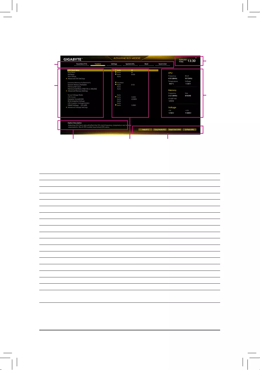
2-2 The Main Menu
Hardware
Information
OptionDescription Current Settings
Setup Menus
Conguration
Items
System
Time
Quick Access Bar allows you to quickly move to
the General Help, Easy Mode, Smart Fan 5, or
Q-Flash screen.
Advanced Mode Function Keys
<f><g>Move the selection bar to select a setup menu
<h><i> Movetheselectionbartoselectancongurationitemonamenu
<Enter>/DoubleClick Execute command or enter a menu
<+>/<PageUp> Increase the numeric value or make changes
<—>/<PageDown> Decreasethenumericvalueormakechanges
<F1> Show descriptions of the function keys
<F2> Switch to Easy Mode
<F3> SavethecurrentBIOSsettingstoaprole
<F4> LoadtheBIOSsettingsfromaprolecreatedbefore
<F5> RestorethepreviousBIOSsettingsforthecurrentsubmenus
<F6> DisplaytheSmartFan5screen
<F7> LoadtheOptimizedBIOSdefaultsettingsforthecurrentsubmenus
<F8> Access the Q-Flash utility
<F10> Save all the changes and exit the BIOS Setup program
<F11> Switch to the Favorites submenu
<F12> Capture the current screen as an image and save it to your USB drive
<Insert> Add or remove a favorite option
<Ctrl>+<S> Displayinformationontheinstalledmemory
<Esc> Main Menu: Exit the BIOS Setup program
Submenus: Exit current submenu
— 20 —

2-3 Favorites (F11)
Setyourfrequentlyusedoptionsasyourfavoritesandusethe<F11>keytoquicklyswitchtothepagewhere
all of your favorite options are located. To add or remove a favorite option, go to its original page and press
<Insert>ontheoption.Theoptionismarkedwithastarsignifsetasa»favorite.»
— 21 —
&CPU Clock Ratio
Allows you to alter the clock ratio for the installed CPU. The adjustable range is dependent on the CPU
being installed.
&Ring Ratio
AllowsyoutosettheCPUUncoreratio.TheadjustablerangeisdependentontheCPUbeingused.(Default:
Auto)
&IGP Ratio (Note)
AllowsyoutosettheGraphicsRatio.(Default:Auto)
&AVX Offset (Note)
AVX offset is the negative offset of AVX ratio.
Advanced CPU Settings
&CPU Over Temperature Protection (Note)
Allowsyoutone-tunetheTJMaxoffsetvalue.(Default:Auto)
&FCLK Frequency for Early Power On
AllowsyoutosettheFCLKfrequency.Optionsare:Normal(800Mhz),1GHz,400MHz.(Default:1GHz)
&Hyper-Threading Technology
Allows you to determine whether to enable multi-threading technology when using an Intel® CPU that
supports this function. This feature only works for operating systems that support multi-processor mode.
AutoletstheBIOSautomaticallycongurethissetting.(Default:Auto)
&No. of CPU Cores Enabled
Allows you to select the number of CPU cores to enable in an Intel® multi-core CPU (the number of CPU
coresmayvarybyCPU).AutoletstheBIOSautomaticallycongurethissetting.(Default:Auto)
&VT-d
Enables or disables Intel®VirtualizationTechnologyforDirectedI/O.(Default:Enabled)
(Note) ThisitemispresentonlywhenyouinstallaCPUthatsupportsthisfeature.Formoreinformationabout
Intel® CPUs’ unique features, please visit Intel’s website.
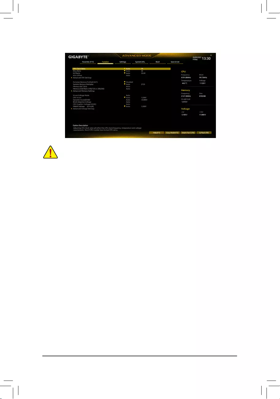
2-4 Tweaker
Whether the system will work stably with the overclock/overvoltage settings you made is dependent on your overall
systemcongurations.Incorrectlydoingoverclock/overvoltagemayresultindamagetoCPU,chipset,ormemory
and reduce the useful life of these components. This page is for advanced users only and we recommend you not to
alter the default settings to prevent system instability or other unexpected results. (Inadequately altering the settings
may result in system’s failure to boot. If this occurs, clear the CMOS values and reset the board to default values.)
— 22 —

&Intel(R) Speed Shift Technology (Intel® Speed Shift Technology) (Note)
Enables or disables Intel® Speed Shift Technology. Enabling this feature allows the processor to ramp up
itsoperatingfrequencymorequicklyandthenimprovesthesystemresponsiveness.(Default:Enabled)
&CPU Thermal Monitor (Note)
Enables or disables Intel® Thermal Monitor function, a CPU overheating protection function. When enabled,
the CPU core frequency and voltage will be reduced when the CPU is overheated. Auto lets the BIOS
automaticallycongurethissetting.(Default:Auto)
&Ring to Core offset (Down Bin)
AllowsyoutodeterminewhethertodisabletheCPURingratioauto-downfunction.Auto lets the BIOS
automaticallycongurethissetting.(Default:Auto)
&CPU EIST Function (Note)
Enables or disables Enhanced Intel®SpeedStepTechnology(EIST).DependingonCPUloading,Intel®
EIST technology can dynamically and effectively lower the CPU voltage and core frequency to decrease
average power consumption and heat production. AutoletstheBIOSautomaticallycongurethissetting.
(Default:Auto)
&Race To Halt (RTH) (Note)/EnergyEfcientTurbo (Note)
Enables or disables the CPU power saving related settings.
&Voltage Optimization
Allowsyoutodeterminewhethertoenablevoltageoptimizationtoreducepowerconsumption.(Default:
Auto)
&Intel(R) Turbo Boost Technology (Note)
Allows you to determine whether to enable the Intel® CPU Turbo Boost technology. Auto lets the BIOS
automaticallycongurethissetting.(Default:Auto)
&Intel(R) Turbo Boost Max Technology 3.0 (Note)
Enables or disables Intel® Turbo Boost Max Technology 3.0. Intel® Turbo Boost Max Technology 3.0 allows
the system to identify the processor’s best performance core and lets you manually direct the most critical
workloadstoit.Youcanevenadjustthefrequencyofeachcoreindividuallyforperformanceoptimization.
(Default:Enabled)
&CPU Flex Ratio Override
EnablesordisablestheCPUFlexRatio.ThemaximumCPUclockratiowillbebasedontheCPU Flex
Ratio Settings value if CPU Clock Ratio is set to Auto.(Default:Disabled)
&CPU Flex Ratio Settings
AllowsyoutosettheCPUFlexRatio.TheadjustablerangemayvarybyCPU.
&Frequency Clipping TVB (Note)
Allows you to enable or disable automatic CPU frequency reduction initiated by Thermal Velocity Boost.
AutoletstheBIOSautomaticallycongurethissetting.(Default:Auto)
&Voltage reduction initiated TVB (Note)
Allows you to enable or disable automatic CPU voltage reduction initiated by Thermal Velocity Boost. Auto
letstheBIOSautomaticallycongurethissetting.(Default:Auto)
dActive Turbo Ratios
&Turbo Ratio (1-Core Active~10-Core Active)
Allows you to set the CPU Turbo ratios for different number of active cores. Auto sets the CPU Turbo
ratiosaccordingtotheCPUspecications.
Thisitemiscongurableonlywhen
Active Turbo Ratios is set
to
Enabled
.
(Default:Auto)
(Note) ThisitemispresentonlywhenyouinstallaCPUthatsupportsthisfeature.Formoreinformationabout
Intel® CPUs’ unique features, please visit Intel’s website.
— 23 —

dC-States Control
&CPU Enhanced Halt (C1E)
Enables or disables Intel
®
CPU Enhanced Halt (C1E) function, a CPU power-saving function in system halt state.
When enabled, the CPU core frequency and voltage will be reduced during system halt state to decrease
power consumption. AutoletstheBIOSautomaticallycongurethissetting.Thisitemiscongurableonly
when C-States Control is set to Enabled.(Default:Auto)
&C3 State Support (Note)
Allows you to determine whether to let the CPU enter C3 mode in system halt state. When enabled, the
CPU core frequency and voltage will be reduced during system halt state to decrease power consumption.
The C3 state is a more enhanced power-saving state than C1. AutoletstheBIOSautomaticallycongure
thissetting.ThisitemiscongurableonlywhenC-States Control is set to Enabled.(Default:Auto)
&C6/C7 State Support (Note)
Allows you to determine whether to let the CPU enter C6/C7 mode in system halt state. When enabled, the
CPU core frequency and voltage will be reduced during system halt state to decrease power consumption.
The C6/C7 state is a more enhanced power-saving state than C3. AutoletstheBIOSautomaticallycongure
thissetting.ThisitemiscongurableonlywhenC-States Control is set to Enabled.(Default:Auto)
&C8 State Support (Note)
Allows you to determine whether to let the CPU enter C8 mode in system halt state. When enabled, the CPU
core frequency and voltage will be reduced during system halt state to decrease power consumption. The
C8 state is a more enhanced power-saving state than C6/C7. AutoletstheBIOSautomaticallycongure
thissetting.ThisitemiscongurableonlywhenC-States Control is set to Enabled.(Default:Auto)
&C10 State Support (Note)
Allows you to determine whether to let the CPU enter C10 mode in system halt state. When enabled, the
CPU core frequency and voltage will be reduced during system halt state to decrease power consumption.
The C10 state is a more enhanced power-saving state than C8. AutoletstheBIOSautomaticallycongure
thissetting.ThisitemiscongurableonlywhenC-States Control is set to Enabled.(Default:Auto)
&Package C State Limit (Note)
Allows you to specify the C-state limit for the processor. AutoletstheBIOSautomaticallycongurethis
setting.ThisitemiscongurableonlywhenC-States Control is set to Enabled.(Default:Auto)
&CPU Power Performance (Note)
AllowsyoutodeterminewhethertoincreaseCPUperformance.(Default:Auto)
dTurbo Power Limits
Allows you to set a power limit for CPU Turbo mode. When the CPU power consumption exceeds the
speciedpowerlimit,theCPUwillautomaticallyreducethecorefrequencyinordertoreducethepower.
AutosetsthepowerlimitaccordingtotheCPUspecications.(Default:Auto)
&Package Power Limit TDP (Watts) / Package Power Limit Time
AllowsyoutosetthepowerlimitforCPUTurbomodeandhowlongittakestooperateatthespeciedpower
limit.Ifthespeciedvalueisexceeded,theCPUwillautomaticallyreducethecorefrequencyinorderto
reduce the power. AutosetsthepowerlimitaccordingtotheCPUspecications.Thisitemiscongurable
only when Turbo Power Limits is set to Enabled.(Default:Auto)
&DRAM Power Limit (Watts) / DRAM Power Limit Time
AllowsyoutosetthepowerlimitformemoryTurbomodeandhowlongittakestooperateatthespecied
power limit. AutoletstheBIOSautomaticallycongurethissetting.Thisitemiscongurableonlywhen
Turbo Power Limits is set to Enabled.(Default:Auto)
(Note) ThisitemispresentonlywhenyouinstallaCPUthatsupportsthisfeature.Formoreinformationabout
Intel® CPUs’ unique features, please visit Intel’s website.
— 24 —

&Core Current Limit (Amps)
AllowsyoutosetacurrentlimitforCPUTurbomode.WhentheCPUcurrentexceedsthespeciedcurrent
limit, the CPU will automatically reduce the core frequency in order to reduce the current. Auto sets the
powerlimitaccordingtotheCPUspecications.ThisitemiscongurableonlywhenTurbo Power Limits
is set to Enabled.(Default:Auto)
dTurbo Per Core Limit Control (Note 1)
AllowsyoutocontroleachCPUcorelimitseparately.(Default:Auto)
&ExtremeMemoryProle(X.M.P.)(Note 2)
AllowstheBIOStoreadtheSPDdataonXMPmemorymodule(s)toenhancememoryperformancewhen
enabled.
Disabled Disablesthisfunction.(Default)
Prole1 UsesProle1settings.
Prole2(Note2) UsesProle2settings.
&System Memory Multiplier
Allows you to set the system memory multiplier. AutosetsmemorymultiplieraccordingtomemorySPD
data.(Default:Auto)
&Memory Ref Clock
Allowsyoutomanuallyadjustthememoryreferenceclock.(Default:Auto)
&Memory Odd Ratio (100/133 or 200/266)
EnabledallowsQclktoruninoddfrequency.(Default:Auto)
Advanced Memory Settings
&Memory Multiplier Tweaker
Providesdifferentlevelsofmemoryauto-tuning.(Default:Auto)
&Channel Interleaving
Enables or disables memory channel interleaving. Enabled allows the system to simultaneously access
different channels of the memory to increase memory performance and stability. Auto lets the BIOS
automaticallycongurethissetting.(Default:Auto)
&Rank Interleaving
Enables or disables memory rank interleaving. Enabled allows the system to simultaneously access different
ranks of the memory to increase memory performance and stability. Auto lets the BIOS automatically
congurethissetting.(Default:Auto)
&Memory Boot Mode
Provides memory detection and training methods.
Auto LetstheBIOSautomaticallycongurethissetting.(Default)
Normal TheBIOSautomaticallyperformsmemorytraining.Pleasenotethatifthesystem
becomes unstable or unbootable, try to clear the CMOS values and reset the board
todefaultvalues.(Refertotheintroductionsofthebattery/clearCMOSjumperin
Chapter 1 for how to clear the CMOS values.)
EnableFastBoot Skipmemorydetectionandtraininginsomespeciccriteriaforfastermemory
boot.
DisableFastBoot Detectandtrainmemoryateverysingleboot.
(Note1) ThisitemispresentonlywhenyouinstallaCPUthatsupportsthisfeature.Formoreinformationabout
Intel® CPUs’ unique features, please visit Intel’s website.
(Note2) ThisitemispresentonlywhenyouinstallaCPUandamemorymodulethatsupportthisfeature.
— 25 —

&Realtime Memory Timing
Allowsyoutone-tunememorytimingsaftertheBIOSstage.(Default:Auto)
&Memory Enhancement Settings
Providesseveralmemoryperformanceenhancementsettings:Auto,RelaxOC,EnhancedStability,Normal,
EnhancedPerformance,HighFrequency,HighDensity,andDDR-4500+.(Default:Auto)
&Memory Channel Detection Message
Allows you to determine whether to show an alert message when the memory is not installed in the optimal
memorychannel.(Default:Enabled)
SPD Info
Displaysinformationontheinstalledmemory.
Memory Channels Timing
d Channels Standard Timing Control, Channels Advanced Timing Control, Channels
Misc Timing Control
Thesesectionsprovidememorytimingsettings.Note:Yoursystemmaybecomeunstableorfailtoboot
after you make changes on the memory timings. If this occurs, please reset the board to default values by
loadingoptimizeddefaultsorclearingtheCMOSvalues.
& Vcore Voltage Mode/CPU Vcore/Dynamic Vcore (DVID)/BCLK Adaptive Voltage/CPU
Graphics Voltage (VAXG)/DRAM Voltage (CH A/B)
These items allow you to adjust the CPU Vcore and memory voltages.
Advanced Voltage Settings
ThissubmenuallowsyoutocongureLoad-LineCalibrationlevel,over-voltageprotectionlevel,andover-
current protection level.
— 26 —

2-5 Settings
Platform Power
&Platform Power Management
EnablesordisablestheActiveStatePowerManagementfunction(ASPM).(Default:Disabled)
&PEG ASPM
AllowsyoutoconguretheASPMmodefor the device connected totheCPUPEGbus.Thisitemis
congurableonlywhenPlatform Power Management is set to Enabled.(Default:Disabled)
&PCH ASPM
AllowsyoutoconguretheASPMmodeforthedeviceconnectedtoChipset’sPCIExpressbus.Thisitem
iscongurableonlywhenPlatform Power Management is set to Enabled.(Default:Disabled)
&DMI ASPM
AllowsyoutoconguretheASPMmodeforbothCPUsideandChipsetsideoftheDMIlink.Thisitemis
congurableonlywhenPlatform Power Management is set to Enabled.(Default:Disabled)
&Power On By Keyboard
Allows the system to be turned on by a PS/2 keyboard wake-up event.
Note:Tousethisfunction,youneedanATXpowersupplyprovidingatleast1Aonthe+5VSBlead.
Disabled Disablesthisfunction.(Default)
Password Set a password with 1~5 characters to turn on the system.
Keyboard98 PressPOWERbuttonontheWindows98keyboardtoturnonthesystem.
Any Key Press any key to turn on the system.
&Power On Password
Set the password when Power On By Keyboard is set to Password.
Press<Enter>onthisitemandsetapasswordwithupto5charactersandthenpress<Enter>toaccept.
Toturnonthesystem,enterthepasswordandpress<Enter>.
Note:Tocancelthepassword,press<Enter>onthisitem.Whenpromptedforthepassword,press<Enter>
again without entering the password to clear the password settings.
&Power On By Mouse
Allows the system to be turned on by a PS/2 mouse wake-up event.
Note:Tousethisfunction,youneedanATXpowersupplyprovidingatleast1Aonthe+5VSBlead.
Disabled Disablesthisfunction.(Default)
Move Move the mouse to turn on the system.
DoubleClick Doubleclickonleftbuttononthemousetoturnonthesystem.
— 27 —

&ErP
DetermineswhethertoletthesystemconsumeleastpowerinS5(shutdown)state.(Default:Disabled)
Note:WhenthisitemissettoEnabled,thefollowingfunctionswillbecomeunavailable:ResumebyAlarm,
power on by mouse, and power on by keyboard.
&Soft-Off by PWR-BTTN
ConguresthewaytoturnoffthecomputerinMS-DOSmodeusingthepowerbutton.
Instant-Off Pressthepowerbuttonandthenthesystemwillbeturnedoffinstantly.(Default)
Delay4Sec. Pressandholdthepowerbuttonfor4secondstoturnoffthesystem.Ifthepower
button is pressed for less than 4 seconds, the system will enter suspend mode.
&Resume by Alarm
Determineswhethertopoweronthesystematadesiredtime.(Default:Disabled)
If enabled, set the date and time as following:
Wakeupday:Turnonthesystemataspecictimeoneachdayoronaspecicdayinamonth.
Wake up hour/minute/second: Set the time at which the system will be powered on automatically.
Note:Whenusingthisfunction,avoidinadequateshutdownfromtheoperatingsystemorremovalofthe
AC power, or the settings may not be effective.
&Power Loading
Enables or disables dummy load. When the power supply is at low load, a self-protection will activate causing
it to shutdown or fail. If this occurs, please set to Enabled. AutoletstheBIOSautomaticallycongurethis
setting.(Default:Auto)
&RC6(Render Standby)
Allows you to determine whether to let the onboard graphics enter standby mode to decrease power
consumption.(Default:Enabled)
&AC BACK
DeterminesthestateofthesystemafterthereturnofpowerfromanACpowerloss.
Memory The system returns to its last known awake state upon the return of the AC power.
Always On The system is turned on upon the return of the AC power.
AlwaysOff ThesystemstaysoffuponthereturnoftheACpower.(Default)
IO Ports
&Initial Display Output
SpeciestherstinitiationofthemonitordisplayfromtheinstalledPCIExpressgraphicscardortheonboard
graphics.
IGFX (Note) Setstheonboardgraphicsastherstdisplay.
PCIe1Slot SetsthegraphicscardonthePCIEX16slotastherstdisplay.(Default)
ThisitemiscongurableonlywhenCSM Support is set to Enabled.
&Internal Graphics
Enablesordisablestheonboardgraphicsfunction.(Default:Auto)
&DVMT Pre-Allocated
Allowsyoutosettheonboardgraphicsmemorysize.(Default:64M)
&DVMT Total Gfx Mem
AllowsyoutoallocatetheDVMTmemorysizeoftheonboardgraphics.Optionsare:128M,256M,MAX.
(Default:256M)
&Aperture Size
Allows you to set the maximum amount of system memory that can be allocated to the graphics card.
Optionsare:128MB,256MB,512MB,1024MB,and2048MB.(Default:256MB)
(Note) ThisitemispresentonlywhenyouinstallaCPUthatsupportsthisfeature.
— 28 —

&Audio Controller
Enablesordisablestheonboardaudiofunction.(Default:Enabled)
If you wish to install a 3rd party add-in audio card instead of using the onboard audio, set this item to
Disabled.
&Above 4G Decoding
Enables or disables 64-bit capable devices to be decoded in above 4 GB address space (only if your system
supports 64-bit PCI decoding). Set to Enabled if more than one advanced graphics card are installed and
their drivers are not able to be launched when entering the operating system (because of the limited 4 GB
memoryaddressspace).(Default:Disabled)
&PCH LAN Controller
EnablesordisablestheonboardLANfunction.(Default:Enabled)
Ifyouwishtoinstalla3rdpartyadd-innetworkcardinsteadofusingtheonboardLAN,setthisitemto
Disabled.
&Wake on LAN Enable
EnablesordisablesthewakeonLANfunction.(Default:Enabled)
&IOAPIC 24-119 Entries
Enablesordisablesthisfunction.(Default:Enabled)
SuperIOConguration
&Serial Port
Enablesordisablestheonboardserialport.(Default:Enabled)
USBConguration
&Legacy USB Support
AllowsUSBkeyboard/mousetobeusedinMS-DOS.(Default:Enabled)
&XHCI Hand-off
Determineswhether toenable XHCIHand-offfeature for an operating system without XHCI Hand-off
support.(Default:Enabled)
&USB Mass Storage Driver Support
EnablesordisablessupportforUSBstoragedevices.(Default:Enabled)
&Mass Storage Devices
DisplaysalistofconnectedUSBmassstoragedevices.ThisitemappearsonlywhenaUSBstoragedevice
is installed.
NetworkStackConguration
&Network Stack
DisablesorenablesbootingfromthenetworktoinstallaGPTformatOS,suchasinstallingtheOSfrom
theWindowsDeploymentServicesserver.(Default:Disabled)
&IPv4 PXE Support
EnablesordisablesIPv4PXESupport.ThisitemiscongurableonlywhenNetwork Stack is enabled.
&IPv4 HTTP Support
EnablesordisablesHTTPbootsupportforIPv4.ThisitemiscongurableonlywhenNetwork Stack is
enabled.
&IPv6 PXE Support
EnablesordisablesIPv6PXESupport.ThisitemiscongurableonlywhenNetwork Stack is enabled.
&IPv6 HTTP Support
EnablesordisablesHTTPbootsupportforIPv6.ThisitemiscongurableonlywhenNetwork Stack is
enabled.
&PXE boot wait time
Allowsyoutocongurehowlongtowaitbeforeyoucanpress<Esc>toabortthePXEboot.Thisitemis
congurableonlywhenNetwork Stackisenabled.(Default:0)
— 29 —

&Media detect count
Allowsyoutosetthenumberoftimestocheckthepresenceofmedia.Thisitemiscongurableonlywhen
Network Stackisenabled.(Default:1)
NVMeConguration
DisplaysinformationonyourM.2NVMEPCIeSSDifinstalled.
SATAAndRSTConguration
&SATA Controller(s)
EnablesordisablestheintegratedSATAcontrollers.(Default:Enabled)
&SATA Mode Selection
EnablesordisablesRAIDfortheSATAcontrollersintegratedintheChipsetorcongurestheSATAcontrollers
to AHCI mode.
IntelRSTPremiumWithIntelOptaneSystemAcceleration EnablesRAIDfortheSATAcontroller.
AHCI CongurestheSATAcontrollerstoAHCImode.AdvancedHostControllerInterface
(AHCI)isaninterfacespecicationthatallowsthestoragedrivertoenableadvanced
SerialATAfeaturessuchasNativeCommandQueuingandhotplug.(Default)
&Aggressive LPM Support
Enables or disables the power saving feature, ALPM (Aggressive Link Power Management), for the Chipset
SATAcontrollers.(Default:Disabled)
&Port 2/3/4/5
EnablesordisableseachSATAport.(Default:Enabled)
&Hot plug
EnablesordisablethehotplugcapabilityforeachSATAport.(Default:Disabled)
&ConguredaseSATA
Enables or disables support for external SATA devices.
EZ RAID
AllowsyoutoquicklysetupaRAIDarray.RefertoChapter3,«ConguringaRAIDSet,»forinstructions
onconguringaRAIDarray.
Intel(R) Ethernet Connection
Thissub-menuprovidesinformationonLANcongurationandrelatedcongurationoptions.
Miscellaneous
&LEDs in System Power On State
AllowsyoutoenableordisablemotherboardLEDlightingwhenthesystemison.
Off Disablestheselectedlightingmodewhenthesystemison.
On Enablestheselectedlightingmodewhenthesystemison.(Default)
&Intel Platform Trust Technology (PTT)
Enables or disables Intel®PTTTechnology.(Default:Disabled)
&Software Guard Extensions (SGX)
Enables or disables the Intel® Software Guard Extensions technology. This feature allows legal software
to operate in a safe environment and protects the software against attacks from malicious software. The
Software Controlled option allows you to enable or disable this feature with an Intel-provided application.
(Default:SoftwareControlled)
&Max Link Speed
Allows you to set the operation mode of the PCI Express slots to Gen 1, Gen 2, or Gen 3. Actual operation
modeissubjecttothehardwarespecicationofeachslot.AutoletstheBIOSautomaticallycongurethis
setting.(Default:Auto)
&3DMark01 Enhancement
Allowsyoutodeterminewhethertoenhancesomelegacybenchmarkperformance.(Default:Disabled)
— 30 —

Trusted Computing
Enables or disables Trusted Platform Module (TPM).
PC Health Status
&Reset Case Open Status
Disabled Keepsorclearstherecordofpreviouschassisintrusionstatus.(Default)
Enabled Clears the record of previous chassis intrusion status and the Case Openeldwill
show»No»atnextboot.
&Case Open
DisplaysthedetectionstatusofthechassisintrusiondetectiondeviceattachedtothemotherboardCI
header.Ifthesystemchassiscoverisremoved,thiseldwillshow«Yes»,otherwiseitwillshow«No».To
clear the chassis intrusion status record, set Reset Case Open Status to Enabled, save the settings to
the CMOS, and then restart your system.
& CPU Vcore/CPU VCCSA/DRAM Channel A/B Voltage/+3.3V/+5V/+12V/CPU VAXG
Displaysthecurrentsystemvoltages.
Smart Fan 5
&Monitor
Allowsyoutoselectatargettomonitorandtomakefurtheradjustment.(Default:CPUFAN)
&Fan Speed Control
Allows you to determine whether to enable the fan speed control function and adjust the fan speed.
Normal Allowsthefantorunatdifferentspeedsaccordingtothetemperature.Youcanadjust
the fan speed with System Information Viewer based on your system requirements.
(Default)
Silent Allows the fan to run at slow speeds.
Manual Allows you to control the fan speed in the curve graph.
Full Speed Allows the fan to run at full speeds.
&Fan Control Use Temperature Input
Allows you to select the reference temperature for fan speed control.
&Temperature Interval
Allows you to select the temperature interval for fan speed change.
&FanControl Mode
Auto Lets the BIOS automatically detect the type of fan installed and sets the optimal control
mode.(Default)
Voltage Voltage mode is recommended for a 3-pin fan.
PWM PWM mode is recommended for a 4-pin fan.
&Fan Stop
Enables or disables the fan stop function. You can set the temperature limit using the temperature curve.
Thefanstopsoperationwhenthetemperatureislowerthanthelimit.(Default:Disabled)
&Temperature
Displaysthecurrenttemperatureoftheselectedtargetarea.
&Fan Speed
Displayscurrentfanspeeds.
&Temperature Warning Control
Sets the warning threshold for temperature. When temperature exceeds the threshold, BIOS will emit
warningsound.Optionsare:Disabled(default),60oC/140oF, 70oC/158oF, 80oC/176oF, 90oC/194oF.
&Fan Fail Warning
Allows the system to emit warning sound if the fan is not connected or fails. Check the fan condition or
fanconnectionwhenthisoccurs.(Default:Disabled)
— 31 —

2-6 System Info.
This section provides information on your motherboard model and BIOS version. You can also select the default
language used by the BIOS and manually set the system time.
&Access Level
Displaysthecurrentaccessleveldependingonthetypeofpasswordprotectionused.(Ifnopasswordis
set, the default will display as Administrator.) The Administrator level allows you to make changes to all
BIOS settings; the User level only allows you to make changes to certain BIOS settings but not all.
&System Language
Selects the default language used by the BIOS.
&System Date
Setsthesystemdate.Thedateformatisweek(read-only),month,date,andyear.Use<Enter>toswitch
betweentheMonth,Date,andYeareldsandusethe<PageUp>or<PageDown>keytosetthedesired
value.
&System Time
Sets the system time. The time format is hour, minute, and second. For example, 1 p.m. is 13:00:00. Use
<Enter>toswitchbetweentheHour,Minute,andSecondeldsandusethe<PageUp>or<PageDown>
key to set the desired value.
Plug in Devices Info
DisplaysinformationonyourPCIExpressandM.2devicesifinstalled.
Q-Flash
AllowsyoutoaccesstheQ-FlashutilitytoupdatetheBIOSorbackupthecurrentBIOSconguration.
— 32 —

2-7 Boot
&Bootup NumLock State
EnablesordisablesNumlockfeatureonthenumerickeypadofthekeyboardafterthePOST.(Default:On)
&Security Option
Specieswhetherapasswordisrequiredeverytimethesystemboots,oronlywhenyouenterBIOSSetup.
Afterconguringthisitem,setthepassword(s)undertheAdministrator Password/User Password item.
Setup A password is only required for entering the BIOS Setup program.
System A password is required for booting the system and for entering the BIOS Setup program.
(Default)
&Full Screen LOGO Show
Allows you to determine whether to display the GIGABYTE Logo at system startup. Disabled skips the
GIGABYTELogowhenthesystemstartsup.(Default:Enabled)
&Boot Option Priorities
Speciestheoverallbootorderfromtheavailabledevices.RemovablestoragedevicesthatsupportGPT
formatwillbeprexedwith«UEFI:»stringonthebootdevicelist.Tobootfromanoperatingsystemthat
supportsGPTpartitioning,selectthedeviceprexedwith»UEFI:»string.
Or if you want to install an operating system that supports GPT partitioning such as Windows 10 64-bit,
selecttheopticaldrivethatcontainstheWindows1064-bitinstallationdiscandisprexedwith«UEFI:»
string.
&Fast Boot
Enables or disables Fast Boot to shorten the OS boot process. Ultra Fast provides the fastest bootup
speed.(Default:DisableLink)
&SATA Support
LastBootSATADevicesOnly Exceptforthepreviousbootdrive,allSATAdevicesaredisabled
beforetheOSbootprocesscompletes.(Default)
AllSATADevices AllSATAdevicesarefunctionalintheoperatingsystemandduringthePOST.
ThisitemiscongurableonlywhenFast Boot is set to Enabled or Ultra Fast.
&VGA Support
Allows you to select which type of operating system to boot.
Auto EnableslegacyoptionROMonly.
EFIDriver EnablesEFIoptionROM.(Default)
ThisitemiscongurableonlywhenFast Boot is set to Enabled or Ultra Fast.
— 33 —

&USB Support
DisableLink AllUSBdevicesaredisabledbeforetheOSbootprocesscompletes.
Full Initial All USB devices are functional in the operating system and during the POST.
(Default)
Partial Initial Part of the USB devices are disabled before the OS boot process completes.
ThisitemiscongurableonlywhenFast Boot is set to Enabled or Ultra Fast. This function is disabled
when Fast Boot is set to Ultra Fast.
&PS2 Devices Support
DisableLink AllPS/2devicesaredisabledbeforetheOSbootprocesscompletes.
Enabled All PS/2 devices are functional in the operating system and during the POST.
(Default)
ThisitemiscongurableonlywhenFast Boot is set to Enabled or Ultra Fast. This function is disabled
when Fast Boot is set to Ultra Fast.
&NetWork Stack Driver Support
DisableLink Disablesbootingfromthenetwork.(Default)
Enabled Enables booting from the network.
ThisitemiscongurableonlywhenFast Boot is set to Enabled or Ultra Fast.
&Next Boot After AC Power Loss
NormalBoot EnablesnormalbootupuponthereturnoftheACpower.(Default)
Fast Boot Keeps the Fast Boot settings upon the return of the AC power.
ThisitemiscongurableonlywhenFast Boot is set to Enabled or Ultra Fast.
&Mouse Speed
Allowsyoutosetthemousecursormovementspeed.(Default:1X)
&Windows 10 Features
Allowsyoutoselecttheoperatingsystemtobeinstalled.(Default:Windows10)
&CSM Support
Enables or disables UEFI CSM (Compatibility Support Module) to support a legacy PC boot process.
Disabled DisablesUEFICSMandsupportsUEFIBIOSbootprocessonly.(Default)
Enabled Enables UEFI CSM.
&LAN PXE Boot Option ROM
AllowsyoutoselectwhethertoenablethelegacyoptionROMfortheLANcontroller.(Default:Disabled)
ThisitemiscongurableonlywhenCSM Support is set to Enabled.
&Storage Boot Option Control
AllowsyoutoselectwhethertoenabletheUEFIorlegacyoptionROMforthestoragedevicecontroller.
Donotlaunch DisablesoptionROM.
UEFI EnablesUEFIoptionROMonly.
Legacy EnableslegacyoptionROMonly.(Default)
ThisitemiscongurableonlywhenCSM Support is set to Enabled.
&Other PCI devices
AllowsyoutoselectwhethertoenabletheUEFIorLegacyoptionROMforthePCIdevicecontrollerother
thantheLAN,storagedevice,andgraphicscontrollers.
Donotlaunch DisablesoptionROM.
UEFI EnablesUEFIoptionROMonly.(Default)
Legacy EnableslegacyoptionROMonly.
ThisitemiscongurableonlywhenCSM Support is set to Enabled.
— 34 —

&Administrator Password
Allowsyoutocongureanadministratorpassword.Press<Enter>onthisitem,typethepassword,and
thenpress<Enter>.Youwillberequestedtoconrmthepassword.Typethepasswordagainandpress
<Enter>.Youmustentertheadministratorpassword(oruserpassword)atsystemstartupandwhenentering
BIOSSetup.Differingfromtheuserpassword,theadministratorpasswordallowsyoutomakechangesto
all BIOS settings.
&User Password
Allowsyoutocongureauserpassword.Press<Enter>onthisitem,typethepassword,andthenpress
<Enter>.Youwillberequestedtoconrmthepassword.Typethepasswordagainandpress<Enter>.
You must enter the administrator password (or user password) at system startup and when entering BIOS
Setup. However, the user password only allows you to make changes to certain BIOS settings but not all.
Tocancelthepassword,press<Enter>onthepassworditemandwhenrequestedforthepassword,enter
thecorrectonerst.Whenpromptedforanewpassword,press<Enter>withoutenteringanypassword.
Press<Enter>againwhenpromptedtoconrm.
NOTE:BeforesettingtheUserPassword,besuretosettheAdministratorPasswordrst.
Secure Boot
AllowsyoutoenableordisableSecureBootandcongurerelatedsettings.Thisitemiscongurableonly
when CSM Support is set to Disabled.
&Preferred Operating Mode
Allows you to select whether to enter Easy mode or Advanced mode after entering BIOS Setup. Auto
enterstheBIOSmodewhereitwaslasttime.(Default:Auto)
— 35 —

2-8 Save & Exit
&Save & Exit Setup
Press<Enter>onthisitemandselectYes. This saves the changes to the CMOS and exits the BIOS Setup
program. Select Noorpress<Esc>toreturntotheBIOSSetupMainMenu.
&Exit Without Saving
Press<Enter>onthisitemandselectYes. This exits the BIOS Setup without saving the changes made
in BIOS Setup to the CMOS. Select Noorpress<Esc>toreturntotheBIOSSetupMainMenu.
&Load Optimized Defaults
Press<Enter>onthisitemandselectYes to load the optimal BIOS default settings. The BIOS defaults
settingshelpthesystemtooperateinoptimumstate.AlwaysloadtheOptimizeddefaultsafterupdating
the BIOS or after clearing the CMOS values.
&Boot Override
Allowsyoutoselectadevicetobootimmediately.Press<Enter>onthedeviceyouselectandselectYes
toconrm.Yoursystemwillrestartautomaticallyandbootfromthatdevice.
&SaveProles
ThisfunctionallowsyoutosavethecurrentBIOSsettingstoaprole.Youcancreateupto8prolesand
saveasSetupProle1~SetupProle8.Press<Enter>tocomplete.OryoucanselectSelect File in
HDD/FDD/USBtosavetheproletoyourstoragedevice.
&LoadProles
If your system becomes unstable and you have loaded the BIOS default settings, you can use this function
toloadtheBIOSsettingsfrom aprolecreatedbefore,withoutthehasslesofreconguring theBIOS
settings.Firstselecttheproleyouwishtoloadandthenpress<Enter>tocomplete.YoucanselectSelect
File in HDD/FDD/USBtoinputtheprolepreviouslycreatedfromyourstoragedeviceorloadtheprole
automatically created by the BIOS, such as reverting the BIOS settings to the last settings that worked
properly (last known good record).
— 36 —

Chapter 3 Appendix
Before you begin, please prepare the following items:
•AtleasttwoSATAharddrivesorSSDs.(Note1) (To ensure optimal performance, it is recommended that you
use two hard drives with identical model and capacity). (Note2)
•Windows setup disc.
•Motherboard driver disc.
•A USB thumb drive.
ConguringtheOnboardSATAController
A. Installing SATA hard drive(s) in your computer
Installtheharddrives/SSDsintheIntel® Chipset controlled connectors on the motherboard. Then connect the
power connectors from your power supply to the hard drives.
B.ConguringSATAcontrollermodeinBIOSSetup
MakesuretoconguretheSATAcontrollermodecorrectlyinsystemBIOSSetup.
Steps:
1. Turnonyourcomputerandpress<Delete>toenterBIOSSetupduringthePOST(Power-OnSelf-Test).Go
to Settings\IOPorts\SATAAndRSTConguration, make sure SATA Controller(s) is enabled. To create
RAID,setSATA Mode Selection to Intel RST Premium With Intel Optane System Acceleration. Then
savethesettingsandrestartyourcomputer.Note:WhenusingaPCIeSSD,makesuretosettheUse RST
Legacy OROM item under Settings\IOPorts\SATAAndRSTConguration to Disabled and RST Control
PCIe Storage Devices to Manual. Then depending the M.2 connector you use, set the corresponding PCIe
Storage Dev On Port XX item to RST Controlled. Finally, save the settings and exit BIOS Setup. If you want
touseNVMePCIeSSDstocongureRAID,makesuretosetNVMe RAID mode to Enabled.
2. TousetheEZRAIDfeature,followthestepsin»C-1.»TocongureUEFIRAID,followthestepsin»C-2.»To
enterthelegacyRAIDROM,referto«C-3″formoreinformation.Finally,savethesettingsandexitBIOSSetup.
3-1 ConguringaRAIDSet
The BIOS Setup menus described in this section may differ from the exact settings for your motherboard.
The actual BIOS Setup menu options you will see shall depend on the motherboard you have and
the BIOS version.
RAID Levels
RAID 0 RAID 1 RAID 5 RAID 10
Minimum
NumberofHard
Drives
≥2 2≥3 4
Array Capacity Numberofhard
drives*Sizeofthe
smallest drive
Sizeofthesmallest
drive
(Numberofhard
drives-1)*Sizeof
the smallest drive
(Numberofhard
drives/2)*Sizeofthe
smallest drive
Fault Tolerance No Yes Yes Yes
C-1. Using EZ RAID
GIGABYTEmotherboardsprovideyouwiththe EZRAIDfeature,allowingyoutoquicklycongureaRAID
arraywithsimpliedsteps.
Steps:
1. After restarting the computer, enter the BIOS Setup and go to Settings.Press<Enter>ontheEZ RAID item.
SelectthetypeofharddrivesyouuseforRAIDintheTypetabandthenpress<Enter>.
2. Go to the ModetabtoselectaRAIDlevel.RAIDlevelssupportedincludeRAID0,RAID1,RAID10,andRAID5
(theselectionsavailabledependonthenumberoftheharddrivesbeinginstalled).Thenpress<Enter>to
move to the Create tab. Click Proceed to begin.
(Note1) AnM.2PCIeSSDcannotbeusedtosetupaRAIDseteitherwithanM.2SATASSDoraSATAharddrive.
(Note2) Referto»InternalConnectors»fortheinstallationnoticesfortheM.2andSATAconnectors.
— 37 —

C-2.UEFIRAIDConguration
Steps:
1. In BIOS Setup, go to Boot and set CSM Support to Disabled. Save the changes and exit BIOS Setup.
2. After the system reboot, enter BIOS Setup again. Then enter the Settings\IO Ports\Intel(R) Rapid Storage
Technology sub-menu.
3. On the Intel(R) Rapid Storage Technologymenu,press<Enter>onCreate RAID Volume to enter the Create
RAID Volume screen. Enter a volume name with 1~16 letters (letters cannot be special characters) under the
Nameitemandpress<Enter>.Then,selectaRAIDlevel.RAIDlevelssupportedincludeRAID0,RAID1,
RAID10,andRAID5(theselectionsavailabledependonthenumberoftheharddrivesbeinginstalled).Next,
use the down arrow key to move to Select Disks.
4. Under Select Disksitem,selecttheharddrivestobeincludedintheRAIDarray.Pressthe<Space>key
ontheharddrivestobeselected(selectedharddrivesaremarkedwith«X»).Thensetthestripeblocksize.
Thestripeblocksizecanbesetfrom4KBto128KB.Onceyouhaveselectedthestripeblocksize,setthe
volume capacity.
5. After setting the capacity, move to Create Volumeandpress<Enter>tobegin.
6. After completing, you’ll be brought back to the Intel(R) Rapid Storage Technology screen. Under RAID
VolumesyoucanseethenewRAIDvolume.Toseemoredetailedinformation,press<Enter>onthevolume
tocheckforinformationonRAIDlevel,stripeblocksize,arrayname,andarraycapacity,etc.
PleasevisitGIGABYTE’swebsitefordetailsonconguringaRAIDarray.
C-3.ConguringLegacyRAIDROM
You’llneedadiscretegraphicscardtoenterthelegacyRAIDROMutility.Enter the Intel®legacyRAIDBIOS
setuputilitytocongureaRAIDarray.SkipthisstepandproceedwiththeinstallationofWindowsoperating
systemforanon-RAIDconguration.
Steps:
1. In BIOS Setup, go to Boot and set CSM Support to Enabled and Storage Boot Option Control to Legacy.
Next,gotoSettings\IOPorts\SATAAndRSTConguration and make sure Use RST Legacy OROM is
set to Enabled. Save the changes and exit BIOS Setup. After the POST memory test begins and before the
operatingsystembootbegins,lookforamessagewhichsays«Press<Ctrl-I>toenterCongurationUtility».
Press<Ctrl>+<I>toentertheRAIDCongurationUtility.
2. Afteryoupress<Ctrl>+<I>,theMAIN MENUscreenwillappear.IfyouwanttocreateaRAIDarray,select
Create RAID VolumeinMAINMENUandpress<Enter>.
3. After entering the CREATE VOLUME MENU screen, enter a volume name with 1~16 letters (letters cannot
be special characters) under the Nameitemandpress<Enter>.Then,selectaRAIDlevel.RAIDlevels
supportedincludeRAID0,RAID1,RAID10,andRAID5(theselectionsavailabledependonthenumberof
theharddrivesbeinginstalled).Press<Enter>toproceed.
4. Under Disksitem,selecttheharddrivestobeincludedintheRAIDarray.Ifonlytwoharddrivesareinstalled,
theywillbeautomaticallyassignedtothearray.Setthestripeblocksizeifnecessary.Thestripeblocksize
canbesetfrom4KBto128KB.Onceyouhaveselectedthestripeblocksize,press<Enter>.
5. Enterthearraycapacityandpress<Enter>.Finallypress <Enter>ontheCreate Volume item to begin
creatingtheRAIDarray.Whenpromptedtoconrmwhethertocreatethisvolume,press<Y>toconrmor
<N>tocancel.
6. Whencompleted,youcanseedetailedinformationabouttheRAIDarrayintheDISK/VOLUME INFORMATION
section,includingtheRAIDlevel,stripeblocksize,arrayname,andarraycapacity,etc.ToexittheRAID
BIOSutility,press<Esc>orselect6. Exit in MAIN MENU.
3. After completing, you’ll be brought back to the Intel(R) Rapid Storage Technology screen. Under RAID
VolumesyoucanseethenewRAIDvolume.Toseemoredetailedinformation,press<Enter>onthevolume
tocheckforinformationonRAIDlevel,stripeblocksize,arrayname,andarraycapacity,etc.
— 38 —

3-2 Installing an Intel® Optane™ Memory
System Requirements
1. Intel® Optane™ memory
2. The Optane™ memory must have at least 16 GB capacity, and it must have equal or smaller capacity than
theharddrive/SSDtobeaccelerated.
3. The Optane™memorycannotbeusedtoaccelerateanexistingRAIDarray;theacceleratedharddrive/SSD
cannotbeincludedinaRAIDarray.
4. Theharddrive/SSDtobeacceleratedmustbeaSATAharddriveorM.2SATASSD.
5. Theharddrive/SSDtobeacceleratedcanbeasystemdriveordatadrive.ThesystemdrivemustbeGPT
formatted and have Windows 10 64-bit (or later version) installed on it. The data drive must also be GPT
formatted.
6. The motherboard driver disc
Installation Guidelines
A-1: Installation in AHCI mode
IftheSATAcontrollerhasbeenconguredinAHCImode,pleasefollowthestepsbelow:
1. After entering the operating system, insert the motherboard driver disc into your optical drive. On the Xpress
Install screen, select Intel(R) Optane(TM) Memory System Acceleration (Note) to install. Follow the on-screen
instructions to continue. When completed, restart the system.
2. After re-entering the operating system, follow the on-screen instructions to complete the settings, and then the
Intel® Optane™ Memory application will appear automatically. If you install more than one Optane™ memory,
please select which one you are going to use. Then select which drive to be accelerated. Click Enable. All
data on the Optane™ memory will be erased. Make sure you back up the data before continuing. Follow the
on-screen instructions to proceed. When completed, restart the system.
3. Launch the Intel® Optane™ Memory application from the Start menu and make sure the Intel® Optane™
Memory has been enabled. (The SATA controller mode is changed to Intel RST Premium With Intel Optane
System AccelerationfromAHCImode.DONOTchangeyourSATAcontrollermodebacktoAHCI.Doing
so will cause the Optane™ memory unable to function properly.)
4. Ifyouwanttoacceleratethesystemdrive,youcanselectspecicfolders,les,orapplicationstoaccelerateusing
the Intel® Optane™ Memory Pinning function. (The Optane™ memory used must have at least 32 GB capacity.)
(Note) IfthesystemalreadyhasIntel®RapidStorageTechnologyutilityinstalled,youhavetoremoveitrst
beforeinstallingtheIntel(R)Optane(TM)MemorySystemAccelerationapplication.
Install the RAID driver and operating system
With the correct BIOS settings, you are ready to install the operating system.
Installing the Operating System
As some operating systems already include Intel®RAIDdriver,youdonotneedtoinstallseparateRAIDdriver
during the Windows installation process. After the operating system is installed, we recommend that you install
allrequireddriversfromthemotherboarddriverdiscusing»XpressInstall»toensuresystemperformanceand
compatibility.IftheoperatingsystemtobeinstalledrequiresthatyouprovideadditionalRAIDdriverduringthe
OS installation process, please refer to the steps below:
1. Copy the IRST folder under \Boot in the driver disc to your USB thumb drive.
2. Boot from the Windows setup disc and perform standard OS installation steps. When the screen requesting
you to load the driver appears, select Browse.
3. ThenbrowsetotheUSBashdriveandselectthelocationofthedriver.Thelocationofthedriverisas
follows:\IRST\f6py-x64
4. When a screen as shown, select Intel(R) Chipset SATA/PCIe RST Premium Controller and click Next to
load the driver and continue the OS installation.
— 39 —

A-2: Installation in Intel RST Premium With Intel Optane System Acceleration mode
IftheSATAcontrollerhasbeenconguredin Intel RST Premium With Intel Optane System Acceleration
mode, please follow the steps below:
1. After system restarts, go to the BIOS Setup, make sure CSM Support under the Boot menu is disabled.
2. Go to Settings\IOPorts\SATAAndRSTConguration and make sure USE RST Legacy OROM is disabled
and RST Control PCIe Storage Devices is set to Manual. If you want to enable the Optane™ memory installed
in the M2A_SB connector, set PCIe Storage Device On Port 9 to RST Controlled.
3. Enter the operating system, launch the Intel® Rapid Storage Technology utility from the Start menu, and
then enable Intel® Optane™ Memory on the Intel® Optane™ Memory screen.
4. If you install more than one Optane™ memory, please select which one you are going to use. Then select
which drive to be accelerated. Click Enable. Follow the on-screen instructions to proceed. When completed,
restart the system.
5. Launch the Intel® Rapid Storage Technology utility from the Start menu and make sure the Intel® Optane™
Memoryhasbeenenabled.Ifyouwanttoacceleratethesystemdrive,youcanselectspecicfolders,les,
or applications to accelerate using the Intel® Optane™ Memory Pinning function. (The Optane™ memory
used must have at least 32 GB capacity.)
•An Optane™memorycannotbeusedtoaccelerateanM.2PCIeSSD.
•If more than one Optane™ memory is installed, you can select only one of them to accelerate your
SATA-based boot drive. The other(s) can only be used as data drive(s).
•DonotabruptlyremovetheOptane™memory.Doingsowillcausetheoperatingsystemtostop
functioning correctly.
•If you want to change/remove the Optane™ memory, you must disable it using the Intel®Rapid
StorageTechnologyorIntel(R)Optane™Memoryapplicationrst.
•After enabling the Optane™ memory, the related BIOS settings will remain even after a BIOS update.
— 40 —
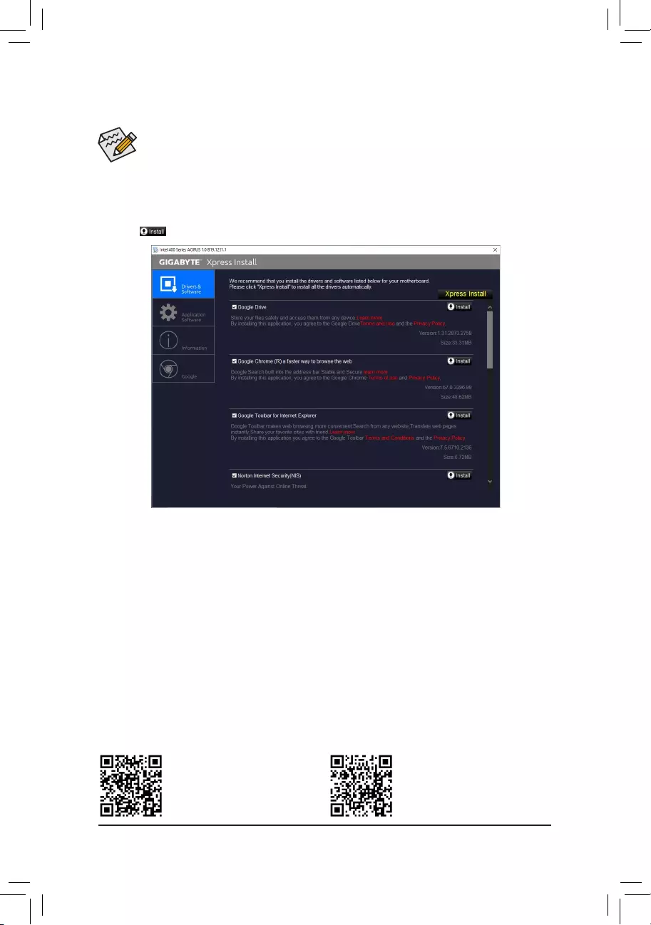
•Beforeinstallingthedrivers,rstinstalltheoperatingsystem.
•After installing the operating system, insert the motherboard driver disc into your optical drive. Click
onthemessage»Taptochoosewhathappenswiththisdisc»onthetop-rightcornerofthescreen
andselect»RunRun.exe.»(OrgotoMyComputer,double-clicktheopticaldriveandexecutethe
Run.exeprogram.)
«XpressInstall»willautomaticallyscanyoursystemandthenlistallofthedriversthatarerecommendedto
install. You can click the Xpress Installbuttonand«XpressInstall»willinstallalloftheselecteddrivers.Orclick
the arrow icon to individually install the drivers you need.
3-3 Drivers Installation
Please visit GIGABYTE’s website for
more software information.
Please visit GIGABYTE’s website for
more troubleshooting information.
— 41 —
Regulatory Notices
United States of America, Federal Communications Commission Statement
This equipment has been tested and found to comply with the limits for a
ClassBdigitaldevice,pursuanttoPart15oftheFCCRules.Theselimits
are designed to provide reasonable protection against harmful interference
in a residential installation. This equipment generates, uses and can radiate
radio frequency energy and, if not installed and used in accordance with
manufacturer’s instructions, may cause harmful interference to radio
communications. However, there is no guarantee that interference will
not occur in a particular installation. If this equipment does cause harmful
interference to radio or television reception, which can be determined by
turning the equipment off and on, the user is encouraged to try to correct
the interference by one or more of the following measures:
•Reorientorrelocatethereceivingantenna.
•Increase the separation between the equipment and receiver.
•Connect the equipment to an outlet on a circuit different from that to
which the receiver is connected.
•Consult the dealer or an experienced radio/TV technician for help.
Canadian Department of Communications Statement
This digital apparatus does not exceed the Class B limits for radio
noiseemissionsfromdigitalapparatussetoutintheRadioInterference
RegulationsoftheCanadianDepartmentofCommunications.Thisclass
B digital apparatus complies with Canadian ICES-003.
Avis de conformité à la réglementation d’Industrie Canada
CetappareilnumériquedelaclasseBestconformeàlanormeNMB-
003 du Canada.
European Union (EU) CE Declaration of Conformity
This device complies with the following directives: Electromagnetic
CompatibilityDirective 2014/30/EU,Low-voltage Directive2014/35/
EU,RoHS directive (recast) 2011/65/EU& the 2015/863 Statement.
This product has been tested and found to comply with all essential
requirementsoftheDirectives.
European Union (EU) RoHS (recast) Directive 2011/65/EU & the
European Commission Delegated Directive (EU) 2015/863 Statement
GIGABYTEproductshavenotintendedtoaddandsafefromhazardous
substances(Cd,Pb,Hg,Cr+6,PBDE,PBB,DEHP,BBP,DBPandDIBP).
ThepartsandcomponentshavebeencarefullyselectedtomeetRoHS
requirement. Moreover, we at GIGABYTE are continuing our efforts to
develop products that do not use internationally banned toxic chemicals.
European Union (EU) Community Waste Electrical & Electronic
Equipment (WEEE) Directive Statement
GIGABYTEwillfulllthenationallawsasinterpretedfromthe2012/19/
EU WEEE (Waste Electrical and Electronic Equipment) (recast) directive.
The WEEE Directive species the treatment, collection, recycling and
disposal of electric and electronic devices and their components. Under
theDirective,usedequipmentmustbemarked,collectedseparately,and
disposed of properly.
WEEE Symbol Statement
The symbol shown below is on the product or on its
packaging, which indicates that this product must not be
disposed of with other waste. Instead, the device should be
taken to the waste collection centers for activation of the
treatment, collection, recycling and disposal procedure.
For more information about where you can drop off your waste equipment
forrecycling,pleasecontactyourlocalgovernmentofce,yourhousehold
waste disposal service or where you purchased the product for details of
environmentally safe recycling.
End of Life Directives-Recycling
The symbol shown below is on the product or on its packaging,
which indicates that this product must not be disposed of with
other waste. Instead, the device should be taken to the waste
collection centers for activation of the treatment, collection,
recycling and disposal procedure.
Déclaration de Conformité aux Directives de l’Union européenne (UE)
Cet appareil portant la marque CE est conforme aux directives de l’UE
suivantes: directive Compatibilité Electromagnétique 2014/30/UE, directive
BasseTension2014/35/UEetdirectiveRoHSII2011/65/UE.Laconformité
à ces directives est évaluée sur la base des normes européennes
harmonisées applicables.
European Union (EU) CE-Konformitätserklärung
DiesesProduktemitCE-KennzeichnungerfüllenfolgendenEU-Richtlinien:
EMV-Richtlinie2014/30/EU,Niederspannungsrichtlinie2014/30/EUund
RoHS-Richtlinie2011/65/EUerfüllt.DieKonformitätmitdiesenRichtlinien
wirdunterVerwendungderentsprechendenStandardszurEuropäischen
Normierungbeurteilt.
CE declaração de conformidade
Este produto com a marcação CE estão em conformidade com das
seguintesDiretivasUE:DiretivaBaixaTensão2014/35/EU;DiretivaCEM
2014/30/EU;DiretivaRSP2011/65/UE.Aconformidadecomestasdiretivas
évericadautilizandoasnormaseuropeiasharmonizadas.
CE Declaración de conformidad
Este producto que llevan la marca CE cumplen con las siguientes
DirectivasdelaUniónEuropea:DirectivaEMC(2014/30/EU),Directiva
debajo voltaje (2014/35/EU), Directiva RoHS (recast) (2011/65/EU).
El cumplimiento de estas directivas se evalúa mediante las normas
europeasarmonizadas.
Dichiarazione di conformità CE
Questo prodotto è conforme alle seguenti direttive: Direttiva sulla
compatibilitàelettromagnetica2014/30/UE,Direttivasullabassatensione
2014/35/UE,Direttiva RoHS (rifusione)2011/65/UE.Questoprodottoè
statotestatoetrovatoconformeatuttiirequisitiessenzialidelleDirettive.
Supplier’s Declaration of Conformity
47 CFR § 2.1077 Compliance Information
Product Name: Motherboard
Trade Name: GIGABYTE
Model Number: H410M H V2
Responsible Party – U.S. Contact Information: G.B.T. Inc.
Address: 17358 Railroad street, City Of Industry, CA91748
Tel.: 1-626-854-9338
Internet contact information: https://www.gigabyte.com
FCC Compliance Statement:
This device complies with Part 15 of the FCC Rules, Subpart B, Unintentional Radiators.
Operation is subject to the following two conditions: (1) This device may not cause harmful interference, and (2) this device
must accept any interference received, including interference that may cause undesired operation.
— 42 —
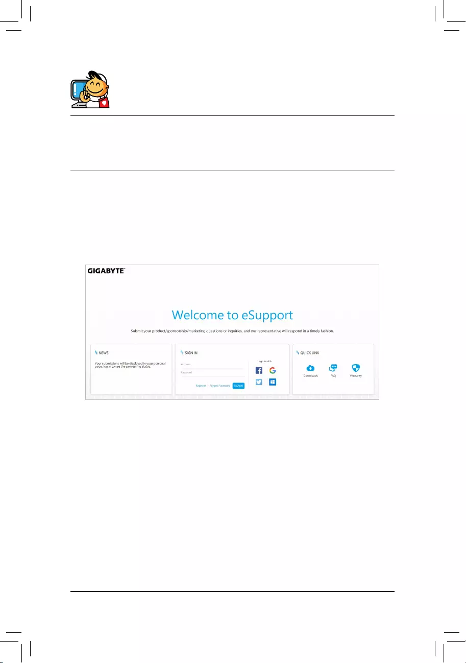
Contact Us
GIGA-BYTE TECHNOLOGY CO., LTD.
Address:No.6,BaoqiangRd.,XindianDist.,NewTaipeiCity231,Taiwan
TEL: +886—2-8912-4000, FAX: +886-2-8912-4005
Tech.andNon-Tech.Support(Sales/Marketing):https://esupport.gigabyte.com
WEB address (English): https://www.gigabyte.com
WEB address (Chinese): https://www.gigabyte.com/tw
•GIGABYTE eSupport
To submit a technical or non-technical (Sales/Marketing) question, please link to:
https://esupport.gigabyte.com
— 43 —
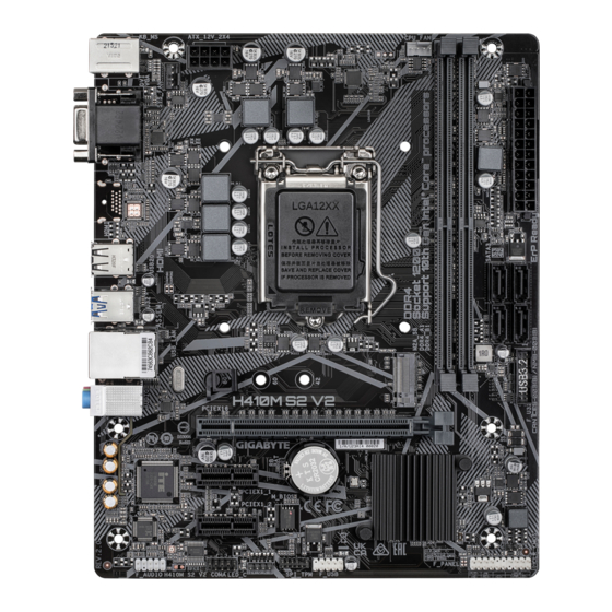
-
Contents
-
Table of Contents
-
Bookmarks
Quick Links
H410M H V2
H410M S2 V2
User’s Manual
Rev. 1801
GIGABYTE will reduce paper use in order to fulfill the responsibilities of a global citizen.
Also, to reduce the impacts on global warming, the packaging materials of this product
are recyclable and reusable. GIGABYTE works with you to protect the environment.
For more product details, please visit GIGABYTE’s website.
Questions and answers
Related Manuals for Gigabyte H410M H V2
Summary of Contents for Gigabyte H410M H V2
Магазин представляет широкий ассортимент компьютерной продукции: процессоры, материнские платы, жесткие диски, оперативная память, корпуса, блоки питания, принтеры, мониторы, модемы и многое другое!
Наши консультаны всегда готовы прийти вам на помощь. Если Вам нужен компьютер для учебы, дома, работы или каких-то других целей, то мы с радостью поможем. Достаточно только указать ваши пожелания, и мы соберем компьютер оптимальной конфигурации.
Уже сегодня Вы можете приобрести бытовую и компьютерную технику в г. Россошь по доступным ценам, не прилагая усилий и не затрачивая времени. Минимальные сроки доставки товара в город Россошь не более 14 дней.
У нас вы можете заправить картриджи и сдать в ремонт свой компьютер. Мы расширяем Ваши представления покупок в Россоши. Совершить покупку У-бегемота.ру легко и просто!
Мы ждем вас по адресу Россошь, ул. Простеева д. 18 2 этаж пн.- пт. 9.00-19.00 сб. — вс. 9.00-16.00;

← Каталог
Цены на материнские платы
☑ Лучшие сборки с материнской платой Gigabyte H410M H mATX LGA1200
-
Процессор Intel Core i5 10400F OEM Comet Lake LGA1200 =5 898 p.
Видеокарта Gigabyte GeForce GTX 1660 6GB OC =14 785 p.12.01.2021
2
2
3.5K
ФСВ
-
Процессор Intel Core i5 10400F BOX Comet Lake LGA1200 =5 598 p.
Видеокарта Gigabyte GeForce GTX 1660 6GB OC =14 785 p.14.07.2021
1
781
Maxim
-
Процессор Intel Core i5 10400F BOX Comet Lake LGA1200 =5 598 p.
Видеокарта Gigabyte GeForce RTX 2060 6GB OC =40 902 p.
☑ Для материнской платы Gigabyte H410M H mATX LGA1200 оптимально подходят комплектующие
Видеокарты
Подходящая видеокарта для материнской платы Gigabyte H410M H mATX LGA1200
Процессоры
Подходящий процессор для материнской платы Gigabyte H410M H mATX LGA1200
Процессор Intel Core i5 10400F OEM Comet Lake LGA1200 (CM8070104290716)
Socket LGA 1200, 6-ядерный 12-поточный, 2900 МГц, Turbo 4300 МГц, CometLake-S, DDR4-2666 МГц, Кэш L3 12 Мб, без видеоядра, 14++ нм, TDP 65 Вт, заблокированный множитель, TRAY
Процессор Intel Core i3 10100F OEM Comet Lake LGA1200 (CM8070104291318)
Socket LGA 1200, 4-ядерный 8-поточный, 3600 МГц, Turbo 4300 МГц, CometLake-S, DDR4-2666 МГц, Кэш L3 6 Мб, без видеоядра, 14++ нм, TDP 65 Вт, заблокированный множитель, TRAY
Процессор Intel Core i5 10400F BOX Comet Lake LGA1200 (BX8070110400F)
Socket LGA 1200, 6-ядерный 12-поточный, 2900 МГц, Turbo 4300 МГц, CometLake-S, DDR4-2666 МГц, Кэш L3 12 Мб, без видеоядра, 14++ нм, TDP 65 Вт, кулер, заблокированный множитель
Оперативная память
Подходящая оперативная память для материнской платы Gigabyte H410M H mATX LGA1200
Жесткие диски HDD
Подходящий жесткий диск для материнской платы Gigabyte H410M H mATX LGA1200
Системы охлаждения
Подходящий кулер для CPU для материнской платы Gigabyte H410M H mATX LGA1200
Кулер DeepCool GAMMAXX400
для процессора, Socket 1151, AM3, AM4, вентиляторы 1х120 мм, 900-1500 об/мин, уровень шума 21.4 — 32.1 дБ, TDP 130 Вт, высота 159 мм, тепловые трубки 4×6 мм, GAMMAXX 400
Кулер DeepCool GAMMAXX300
для процессора, Socket 1151, 1366, AM4, 120×120 мм, 900-1600 об/мин, алюминий + медь GAMMAXX 300, TDP 130 Вт
Кулер ID-COOLING SE-213V2
для процессора, Socket 1151, 2066, AM4, FM2, 120 мм, 800-1600 об/мин, 3 трубки, алюминий, макс. уровень шума 20 dB, TDP 130 Вт, алюминий
Блоки питания
Подходящий блок питания для материнской платы Gigabyte H410M H mATX LGA1200
Корпуса
Подходящий корпус для материнской платы Gigabyte H410M H mATX LGA1200

Корпус Zalman i3 Edge Black
ATX, Midi-Tower, с окном, 2xUSB 2.0, USB 3.0, вентиляторы 4×120 мм, реобас, длина видеокарты 360 мм, высота кулера 172 мм, белая подсветка
Твердотельные диски SSD
Подходящий твердотельный накопитель для материнской платы Gigabyte H410M H mATX LGA1200
Вентиляторы для корпуса
Подходящий вентилятор для корпуса для материнской платы Gigabyte H410M H mATX LGA1200
Мониторы
Подходящий монитор для материнской платы Gigabyte H410M H mATX LGA1200
Монитор BenQ 22″ GW2270HM
21.5″, AMVA+, широкоформатный, LED, 1920×1080, 5 мс, 20000000:1, 178°/178°, VGA, DVI, HDMI, динамики, чёрный
Монитор AOC 27″ C27G1
27″, VA, широкоформатный 16:9, LED, FHD 1920×1080, 144 Гц, 1 мс, 80M:1, 250 кд/м2, 178°/178°, VGA, 2xHDMI, DisplayPort, FreeSync, чёрный
Монитор AOC 24″ C24G1 Gaming
24″, VA, широкоформатный 16:9, LED, FHD 1920×1080, 144 Гц, 1 мс, 80M:1, 250 кд/м2, 178°/178°, VGA, HDMI, DisplayPort, FreeSync, чёрный
* Рейтинг оптимальных комплектующих совместимых с материнской платой Gigabyte H410M H mATX LGA1200 составлен на основе выбора и рекомендаций пользователей ХардПрайс.
Какую материнскую плату выбрать для компьютера Комплектующие для материнской платы Gigabyte H410M H mATX LGA1200.
Где купить компьютер и подобрать комплектующие для сборки ПК по низким ценам? В Hardprice! Сравнить цены на компьютерные комплектующие для сборки компьютера.
Мониторинг, история и динамика цен на компьютеры.
Информация, указанная на сайте, не является публичной офертой. Цены действительны для Москвы и Московской области.
Регион Москва.
Все цены представлены без учета скидок для постоянных клиентов и без учета стоимости доставки.
Сравнить
цены на компьютеры,
помощь в подборе комплектующих для ПК. Хард Прайс.
28.05.2025 Курс валют
USD
79.62 -0.04
EUR
90.9 0.44
UAH
1.91 -0.01