

To reduce the impacts on global warming, the packaging materials of this product
are recyclable and reusable. GIGABYTE works with you to protect the environment.
For more product details, please visit GIGABYTE’s website.
Z590 UDZ590 UD AC
Z590 UD AC
Z590 UD
User’s Manual
Rev. 1102
12ME-Z59UDAC-1102R
Copyright
© 2021 GIGA-BYTE TECHNOLOGY CO., LTD. All rights reserved.
The trademarks mentioned in this manual are legally registered to their respective owners.
Disclaimer
Information in this manual is protected by copyright laws and is the property of GIGABYTE.
Changes to the specications and features in this manual may be made by GIGABYTE without prior
notice. No part of this manual may be reproduced, copied, translated, transmitted, or published in
any form or by any means without GIGABYTE’s prior written permission.
In order to assist in the use of this product, carefully read the User’s Manual.
For product-related information, check on our website at: https://www.gigabyte.com
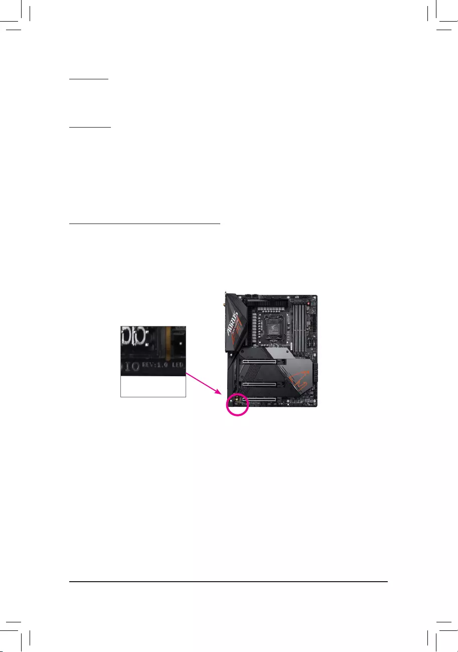
Identifying Your Motherboard Revision
The revision number on your motherboard looks like this: «REV: X.X.» For example, «REV: 1.0»
means the revision of the motherboard is 1.0. Check your motherboard revision before updating
motherboard BIOS, drivers, or when looking for technical information.
Example:
— 2 —

— 3 —
Table of Contents
Z590 UD (AC) Motherboard Layout ………………………………………………………………………4
Chapter 1 Hardware Installation ………………………………………………………………………….5
1-1 Installation Precautions ………………………………………………………………………… 5
1-2 Product Specications ………………………………………………………………………….. 6
1-3 Installing the CPU ……………………………………………………………………………… 10
1-4 Installing the Memory …………………………………………………………………………. 10
1-5 Installing an Expansion Card ………………………………………………………………. 11
1-6 Back Panel Connectors ………………………………………………………………………. 11
1-7 Internal Connectors ……………………………………………………………………………. 13
Chapter 2 BIOS Setup ……………………………………………………………………………………..24
2-1 Startup Screen ………………………………………………………………………………….. 24
2-2 The Main Menu …………………………………………………………………………………. 25
2-3 Smart Fan 6 …………………………………………………………………………………….. 26
2-4 Favorites (F11) ………………………………………………………………………………….. 27
2-5 Tweaker ……………………………………………………………………………………………. 28
2-6 Settings ……………………………………………………………………………………………. 33
2-7 System Info. ……………………………………………………………………………………… 38
2-8 Boot …………………………………………………………………………………………………. 39
2-9 Save & Exit ……………………………………………………………………………………….. 42
Chapter 3 Appendix …………………………………………………………………………………………43
3-1 Conguring a RAID Set ………………………………………………………………………. 43
3-2 Installing Intel® Optane™ Memory and Storage Management …………………… 44
3-3 Drivers Installation ……………………………………………………………………………… 46
Regulatory Notices ………………………………………………………………………………………. 47
Contact Us …………………………………………………………………………………………………. 52
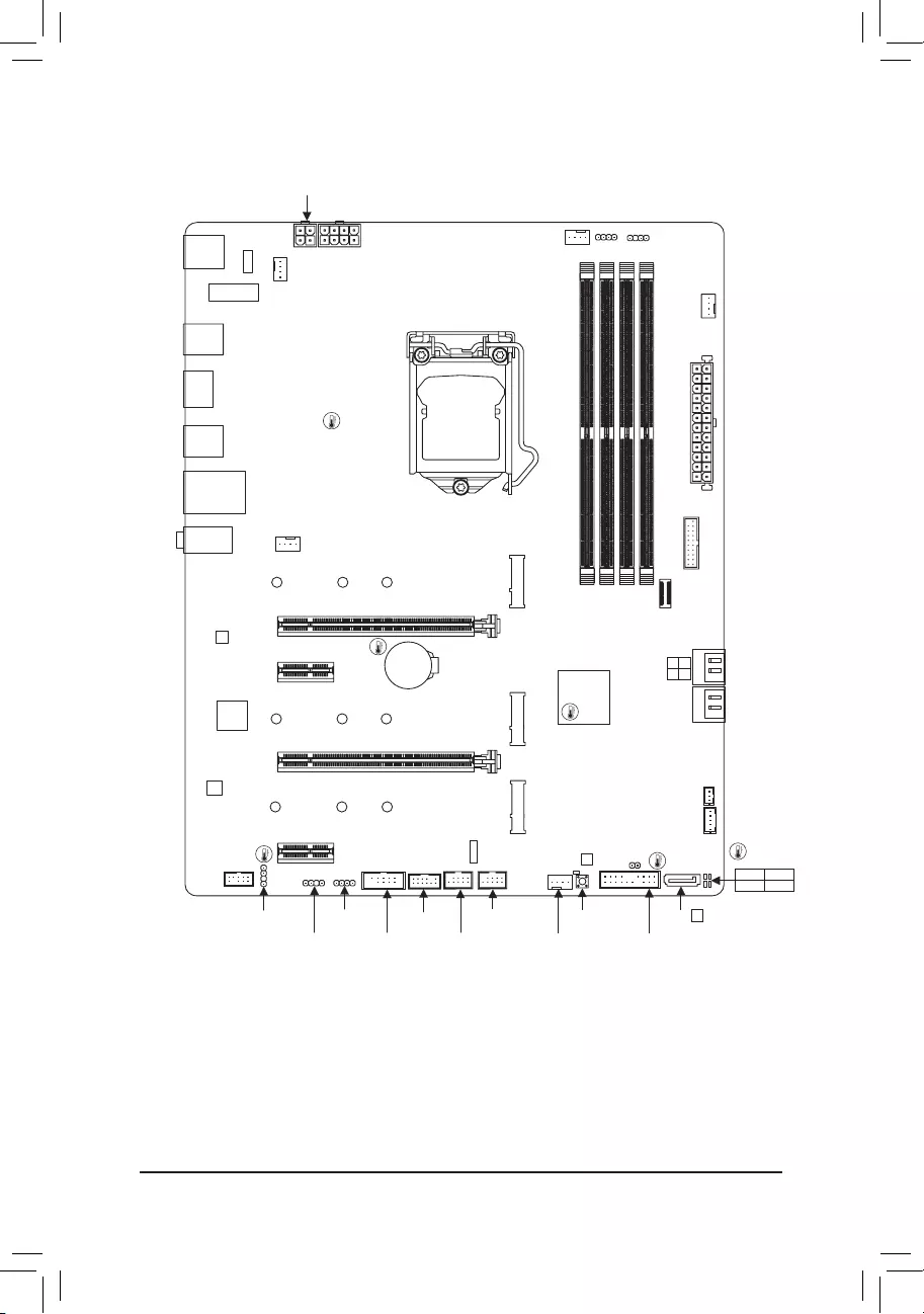
— 4 —
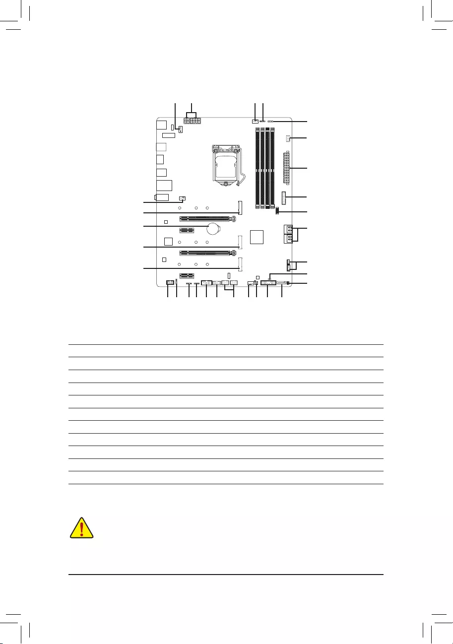
Z590 UD (AC) Motherboard Layout
* The box contents above are for reference only and the actual items shall depend on the product package you obtain.
The box contents are subject to change without notice.
Box Contents
5Z590 UD AC or Z590 UD motherboard 5Two SATA cables
5Motherboard driver disc 5One antennajk
5User’s Manual 5M.2 screws
KB_MS_
USB
DP
U32G2
U32_LAN
LGA1200
ATX
AUDIO
ATX_12V_2X4
Intel® Z590
CLR_CMOS
M_BIOS
PCIEX1_1
PCIEX4
PCIEX16
PCIEX1_2
F_U32
M2P_CPU
CODEC
Z590 UD (AC)
F_PANEL
F_USB2
LED_C1
F_AUDIO
COM
SPI_TPM
SYS_FAN1
SYS_FAN3
CPU_FAN
iTE®
Super I/O
80
SATA3 4 2
3 1
BAT
Realtek®
GbE LAN
CPU DRAM
VGA BOOT
U32
THB_C1
M2M_SB
ATX_12V_2X2
DDR4_B1
DDR4_B2
DDR4_A1
DDR4_A2
D_LED2
LED_C2
QFLASH_PLUS
60110
M2A_SB
SYS_FAN4D_LED1
SPDIF_O
j Only for the Z590 UD AC rev. 1.0.
k Only for the Z590 UD AC rev. 1.1.
QFLED
THB_C2
F_U32C
SYS_FAN2
80 60110
80 60110
F_USB1 SATA3 5
Temperature
sensor
USB 2.0 Hub
M2_WIFIjk
USB 2.0 Hub

Chapter 1 Hardware Installation
1-1 Installation Precautions
The motherboard contains numerous delicate electronic circuits and components which can become
damaged as a result of electrostatic discharge (ESD). Prior to installation, carefully read the user’s
manual and follow these procedures:
•Prior to installation, make sure the chassis is suitable for the motherboard.
•Prior to installation, do not remove or break motherboard S/N (Serial Number) sticker or
warranty sticker provided by your dealer. These stickers are required for warranty validation.
•Always remove the AC power by unplugging the power cord from the power outlet before
installing or removing the motherboard or other hardware components.
•When connecting hardware components to the internal connectors on the motherboard, make
sure they are connected tightly and securely.
•When handling the motherboard, avoid touching any metal leads or connectors.
•It is best to wear an electrostatic discharge (ESD) wrist strap when handling electronic
components such as a motherboard, CPU or memory. If you do not have an ESD wrist strap,
keep your hands dry and rst touch a metal object to eliminate static electricity.
•Prior to installing the motherboard, please have it on top of an antistatic pad or within an
electrostatic shielding container.
•Before connecting or unplugging the power supply cable from the motherboard, make sure
the power supply has been turned off.
•Before turning on the power, make sure the power supply voltage has been set according to
the local voltage standard.
•Before using the product, please verify that all cables and power connectors of your hardware
components are connected.
•To prevent damage to the motherboard, do not allow screws to come in contact with the
motherboard circuit or its components.
•Make sure there are no leftover screws or metal components placed on the motherboard or
within the computer casing.
•Do not place the computer system on an uneven surface.
•Do not place the computer system in a high-temperature or wet environment.
•Turning on the computer power during the installation process can lead to damage to system
components as well as physical harm to the user.
•If you are uncertain about any installation steps or have a problem related to the use of the
product, please consult a certied computer technician.
•If you use an adapter, extension power cable, or power strip, ensure to consult with its installation
and/or grounding instructions.
— 5 —

1-2 ProductSpecications
CPU LGA1200 package:
— 11th Generation Intel® Core™ i9 processors/Intel® Core™ i7 processors/
Intel® Core™ i5 processors
— 10th Generation Intel® Core™ i9 processors/Intel® Core™ i7 processors/
Intel® Core™ i5 processors/Intel® Core™ i3 processors/Intel® Pentium®
processors/Intel® Celeron® processors*
* Limited to processors with 4 MB Intel® Smart Cache, Intel® Celeron® G5xx5 family.
(Go to GIGABYTE’s website for the latest CPU support list.)
L3 cache varies with CPU
Chipset Intel® Z590 Express Chipset
Memory 11th Generation Intel® Core™ i9/i7/i5 processors:
— Support for DDR4 3200/3000/2933/2666/2400/2133 MHz memory
modules
10th Generation Intel® Core™ i9/i7 processors:
— Support for DDR4 2933/2666/2400/2133 MHz memory modules
10th Generation Intel® Core™ i5/i3/Pentium®/Celeron® processors:
— Support for DDR4 2666/2400/2133 MHz memory modules
4 x DDR4 DIMM sockets supporting up to 128 GB (32 GB single DIMM capacity)
of system memory
Dual channel memory architecture
Support for ECC Un-buffered DIMM 1Rx8/2Rx8 memory modules (operate in
non-ECC mode)
Support for non-ECC Un-buffered DIMM 1Rx8/2Rx8/1Rx16 memory modules
Support for Extreme Memory Prole (XMP) memory modules
(Go to GIGABYTE’s website for the latest supported memory speeds and memory
modules.)
Onboard
Graphics
Integrated Graphics Processor-Intel® HD Graphics support:
— 1 x DisplayPort, supporting a maximum resolution of 4096×2304@60 Hz
* Support for DisplayPort 1.2 version and HDCP 2.3
(Graphics specications may vary depending on CPU support.)
Audio Realtek® audio CODEC
High Denition Audio
2/4/5.1/7.1-channel
* To congure 7.1-channel audio, you need to open the audio software and select
Device advanced settings > Playback Device to change the default setting rst.
Please visit GIGABYTE’s website for details on conguring the audio software.
Support for S/PDIF Out
LAN Realtek® 2.5GbE LAN chip (2.5 Gbit/1 Gbit/100 Mbit)
Wireless
Communication
Modulejk
Intel® Wi-Fi AC 9462j/9560k:
— Intel® CNVi interface 802.11a/b/g/n/ac, supporting 2.4/5 GHz Dual-Band
— BLUETOOTH 5.1
— Support for 1×1 11ac wireless standard and up to 433 Mbps data ratej
— Support for 2×2 11ac wireless standard and up to 1.73 Gbps data ratek
* Actual data rate may vary depending on environment and equipment.
j Only for the Z590 UD AC rev. 1.0.
k Only for the Z590 UD AC rev. 1.1.
— 6 —

Expansion Slots 1 x PCI Express x16 slot, running at x16 (PCIEX16)
* For optimum performance, if only one PCI Express graphics card is to be installed,
be sure to install it in the PCIEX16 slot.
(The PCIEX16 slot conforms to PCI Express 4.0 standard.) (Note)
1 x PCI Express x16 slot, running at x4 (PCIEX4)
2 x PCI Express x1 slots
(The PCIEX4 and PCIEX1 slots conform to PCI Express 3.0 standard.)
Multi-Graphics
Technology Support for AMD Quad-GPU CrossFire™ and 2-Way AMD CrossFire™ technologies
Storage Interface CPU:
— 1 x M.2 connector (Socket 3, M key, type 2260/2280/22110 PCIe 4.0 x4 SSD
support) (M2P_CPU) (Note)
Chipset:
— 1 x M.2 connector (Socket 3, M key, type 2260/2280/22110 SATA and PCIe
3.0 x4/x2 SSD support) (M2A_SB)
— 1 x M.2 connector (Socket 3, M key, type 2260/2280/22110 PCIe 3.0 x4/x2
SSD support) (M2M_SB)
5 x SATA 6Gb/s connectors
Support for RAID 0, RAID 1, RAID 5, and RAID 10
* Refer to «1-7 Internal Connectors,» for the installation notices for the M.2 and SATA
connectors.
Intel® Optane™ Memory Ready
USB Chipset:
— 2 x USB 3.2 Gen 2 Type-A ports (red) on the back panel
— 6 x USB 3.2 Gen 1 ports (4 ports on the back panel, 2 ports available through
the internal USB header)
— 1 x USB Type-C® port with USB 3.2 Gen 1 support, available through the
internal USB header
Chipset+2 USB 2.0 Hubs:
— 6 x USB 2.0/1.1 ports (2 ports on the back panel, 4 ports available through
the internal USB headers)
Internal
Connectors
1 x 24-pin ATX main power connector
1 x 8-pin ATX 12V power connector
1 x 4-pin ATX 12V power connector
1 x CPU fan header
4 x system fan headers
2 x addressable LED strip headers
2 x RGB LED strip headers
1 x Q-Flash Plus button
5 x SATA 6Gb/s connectors
3 x M.2 Socket 3 connectors
1 x front panel header
1 x front panel audio header
1 x S/PDIF Out header
1 x USB 3.2 Gen 1 header
(Note) Supported by 11th Generation processors only.
— 7 —
Internal
Connectors
1 x USB Type-C® header, with USB 3.2 Gen 1 support
2 x USB 2.0/1.1 headers
1 x Trusted Platform Module header (For the GC-TPM2.0 SPI/GC-TPM2.0 SPI
2.0 module only)
2 x Thunderbolt™ add-in card connectors
1 x serial port header
1 x Clear CMOS jumper
Back Panel
Connectors
1 x PS/2 keyboard/mouse port
2 x SMA antenna connectors (1T1R)j(2T2R)k
1 x DisplayPort
2 x USB 3.2 Gen 2 Type-A ports (red)
4 x USB 3.2 Gen 1 ports
2 x USB 2.0/1.1 ports
1 x RJ-45 port
3 x audio jacks
I/O Controller iTE® I/O Controller Chip
Hardware
Monitor
Voltage detection
Temperature detection
Fan speed detection
Fan fail warning
Fan speed control
* Whether the fan speed control function is supported will depend on the cooler you
install.
BIOS 1 x 256 Mbit ash
Use of licensed AMI UEFI BIOS
PnP 1.0a, DMI 2.7, WfM 2.0, SM BIOS 2.7, ACPI 5.0
Unique Features Support for APP Center
* Available applications in APP Center may vary by motherboard model. Supported
functions of each application may also vary depending on motherboard specications.
— @BIOS
— EasyTune
— Fast Boot
— Game Boost
— ON/OFF Charge
— RGB Fusion
— Smart Backup
— System Information Viewer
Support for Q-Flash Plus
Support for Q-Flash
Support for Xpress Install
j Only for the Z590 UD AC rev. 1.0.
k Only for the Z590 UD AC rev. 1.1.
(Note) Supported by 11th Generation processors only.
— 8 —
Bundled
Software
Norton® Internet Security (OEM version)
Realtek® 8125 Gaming LAN Bandwidth Control Utility
Operating
System Support for Windows 10 64-bit
Form Factor ATX Form Factor; 30.5cm x 24.4cm
* GIGABYTE reserves the right to make any changes to the product specications and product-related information without
prior notice.
Please visit GIGABYTE’s website for support lists of CPU, memory modules,
SSDs, and M.2 devices.
Z590 UD AC Z590 UD
Please visit the Support\Utility List page on GIGABYTE’s website to download the latest
version of apps.
— 9 —
1-3 Installing the CPU
Read the following guidelines before you begin to install the CPU:
•Make sure that the motherboard supports the CPU.
(Go to GIGABYTE’s website for the latest CPU support list.)
•Always turn off the computer and unplug the power cord from the power outlet before installing the
CPU to prevent hardware damage.
•Locate the pin one of the CPU. The CPU cannot be inserted if oriented incorrectly. (Or you may
locate the notches on both sides of the CPU and alignment keys on the CPU socket.)
•Apply an even and thin layer of thermal grease on the surface of the CPU.
•Do not turn on the computer if the CPU cooler is not installed, otherwise overheating and damage
of the CPU may occur.
•Set the CPU host frequency in accordance with the CPU specications. It is not recommended
that the system bus frequency be set beyond hardware specications since it does not meet the
standard requirements for the peripherals. If you wish to set the frequency beyond the standard
specications, please do so according to your hardware specications including the CPU, graphics
card, memory, hard drive, etc.
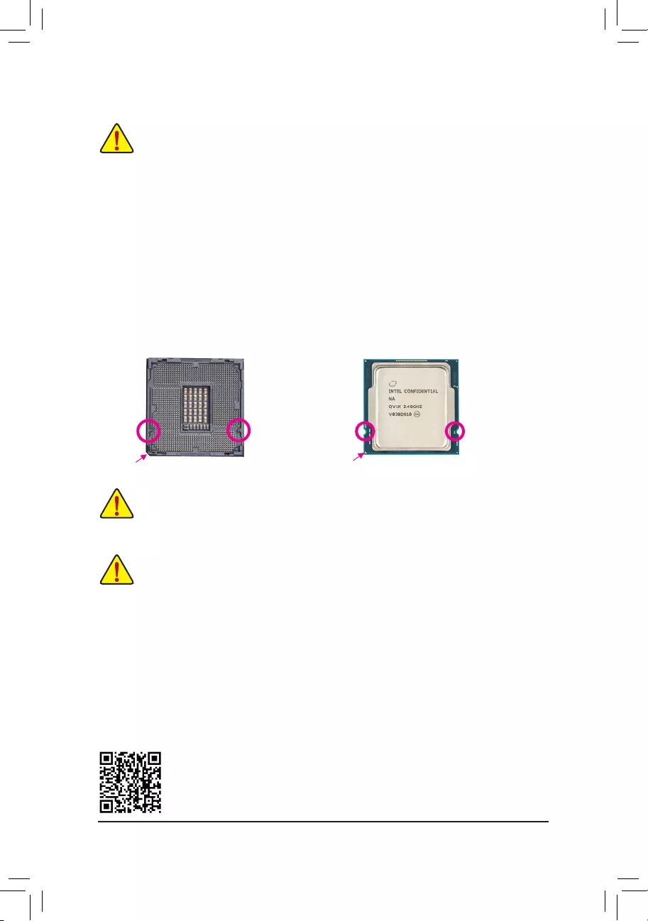
Installing the CPU
Locate the alignment keys on the motherboard CPU socket and the notches on the CPU.
Do not remove the CPU socket cover before inserting the CPU. It may pop off from the load
plate automatically during the process of re—engaging the lever after you insert the CPU.
1-4 Installing the Memory
Read the following guidelines before you begin to install the memory:
•Make sure that the motherboard supports the memory. It is recommended that memory of the same
capacity, brand, speed, and chips be used.
(Go to GIGABYTE’s website for the latest supported memory speeds and memory modules.)
•Always turn off the computer and unplug the power cord from the power outlet before installing the
memory to prevent hardware damage.
•Memory modules have a foolproof design. A memory module can be installed in only one direction.
If you are unable to insert the memory, switch the direction.
Please visit GIGABYTE’s website for details on hardware installation.
Triangle Pin One Marking on the CPU
NotchNotch
LGA1200 CPU
Alignment
Key
Alignment
Key
LGA1200 CPU Socket
Pin One Corner of the CPU Socket
DualChannelMemoryConguration
This motherboard provides four memory sockets and supports Dual Channel Technology. After the memory
is installed, the BIOS will automatically detect the specications and capacity of the memory. Enabling Dual
Channel memory mode will double the original memory bandwidth.
The four memory sockets are divided into two channels and each channel has two memory sockets as following:
Channel A: DDR4_A1, DDR4_A2
Channel B: DDR4_B1, DDR4_B2
— 10 —
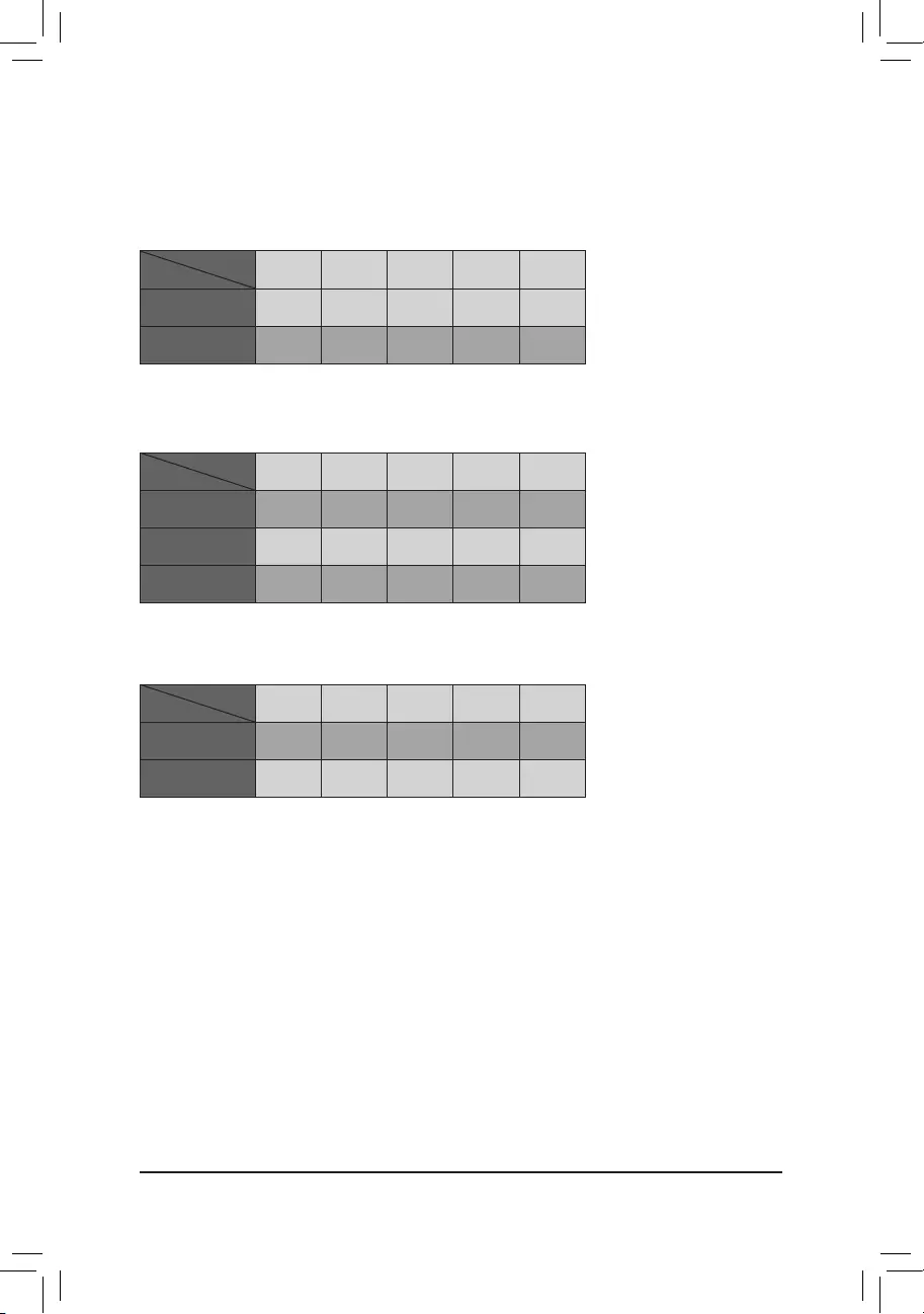
Recommanded Dual Channel Memory Conguration:
DDR4_A1 DDR4_A2 DDR4_B1 DDR4_B2
2 Modules — — DS/SS — — DS/SS
4 Modules DS/SS DS/SS DS/SS DS/SS
(SS=Single-Sided, DS=Double-Sided, «- -«=No Memory)
Due to CPU limitations, read the following guidelines before installing the memory in Dual Channel mode.
1. Dual Channel mode cannot be enabled if only one memory module is installed.
2. When enabling Dual Channel mode with two or four memory modules, it is recommended that memory
of the same capacity, brand, speed, and chips be used.
1-5 Installing an Expansion Card
Read the following guidelines before you begin to install an expansion card:
•Make sure the motherboard supports the expansion card. Carefully read the manual that came
with your expansion card.
•Always turn off the computer and unplug the power cord from the power outlet before installing an
expansion card to prevent hardware damage.
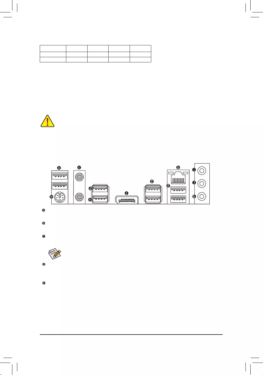
1-6 Back Panel Connectors
USB 2.0/1.1 Port
The USB port supports the USB 2.0/1.1 specication. Use this port for USB devices.
PS/2 Keyboard/Mouse Port
Use this port to connect a PS/2 mouse or keyboard.
SMA Antenna Connectors (1T1R)j(2T2R)k
Use this connector to connect an antenna.
jk
USB 3.2 Gen 2 Type-A Port (Red)
The USB 3.2 Gen 2 port supports the USB 3.2 Gen 2 specication and is compatible to the USB 3.2 Gen 1
and USB 2.0 specication. Use this port for USB devices.
USB 3.2 Gen 2 Type-A Port (Red) (Q-Flash Plus Port)
The USB 3.2 Gen 2 port supports the USB 3.2 Gen 2 specication and is compatible to the USB 3.2 Gen 1 and
USB 2.0 specication. Before using Q-Flash Plus (Note), make sure to insert the USB ash drive into this port rst.
Tighten the antennas to the antenna connectors and then aim the antennas correctly for better
signal reception.
j Only for the Z590 UD AC rev. 1.0.
k Only for the Z590 UD AC rev. 1.1.
(Note) To enable the Q-Flash Plus function please visit the «Unique Features» webpage of GIGABYTE’s website.
— 11 —
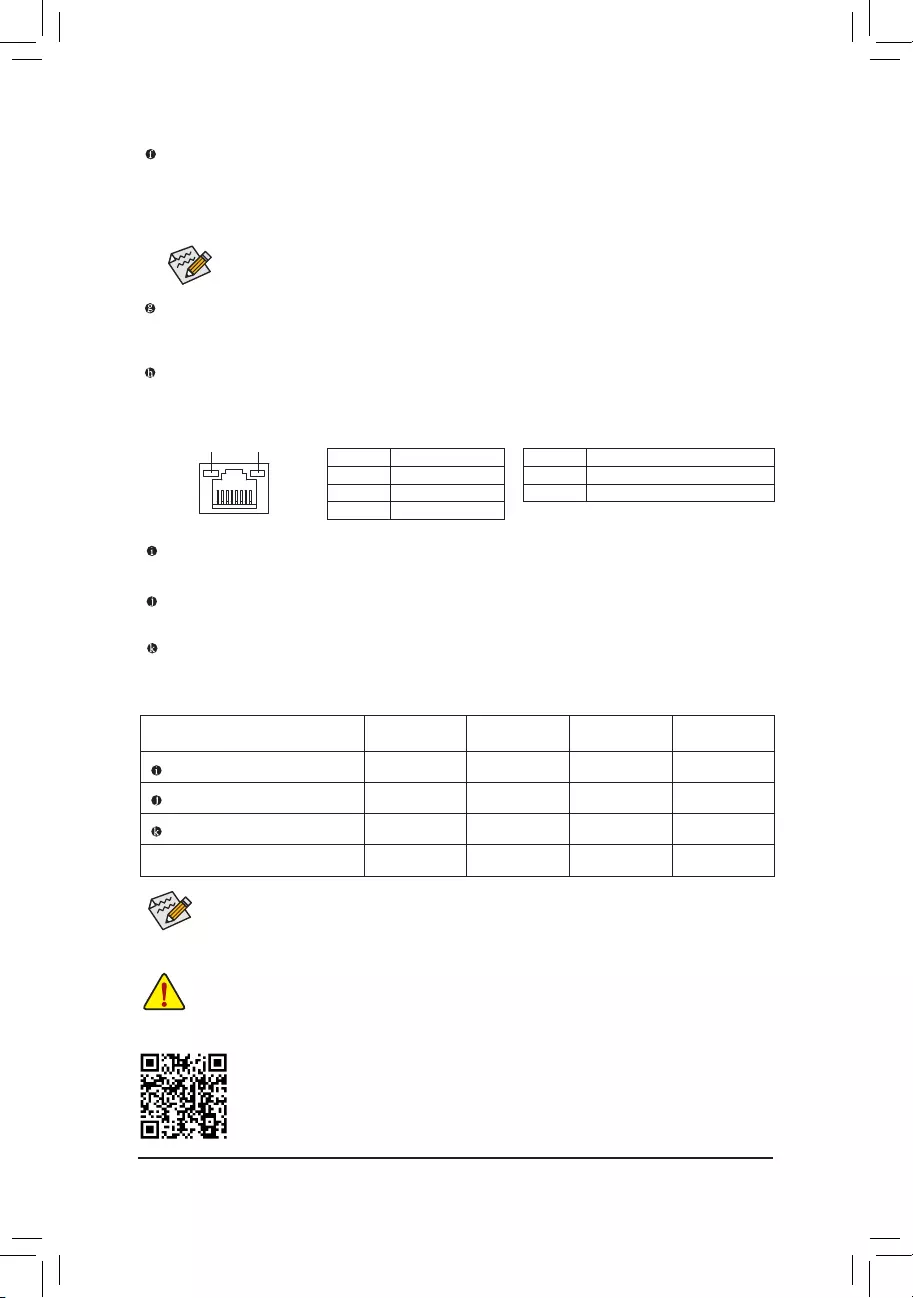
Activity LED
Connection/
Speed LED
LAN Port
Activity LED:Connection/Speed LED:
State Description
Orange 2.5 Gbps data rate
Green 1 Gbps data rate
Off 100 Mbps data rate
State Description
Blinking Data transmission or receiving is occurring
Off No data transmission or receiving is occurring
DisplayPort
DisplayPort delivers high quality digital imaging and audio, supporting bi-directional audio transmission.
DisplayPort can support HDCP 2.3 content protection mechanisms. You can use this port to connect your
DisplayPort-supported monitor. Note: The DisplayPort Technology can support a maximum resolution of
4096×2304@60 Hz but the actual resolutions supported depend on the monitor being used.
Please visit GIGABYTE’s website for details on conguring the audio software.
•When removing the cable connected to a back panel connector, rst remove the cable from your
device and then remove it from the motherboard.
•When removing the cable, pull it straight out from the connector. Do not rock it side to side to
prevent an electrical short inside the cable connector.
Audio Jack Congurations:
Jack Headphone/
2-channel 4-channel 5.1-channel 7.1-channel
Line In/Rear Speaker Out a a a
Line Out/Front Speaker Out a a a a
Mic In/Center/Subwoofer Speaker Out a a
Front Panel Line Out/Side Speaker Out a
USB 3.2 Gen 1 Port
The USB 3.2 Gen 1 port supports the USB 3.2 Gen 1 specication and is compatible to the USB 2.0
specication. Use this port for USB devices.
RJ-45 LAN Port
The Gigabit Ethernet LAN port provides Internet connection at up to 2.5 Gbps data rate. The following
describes the states of the LAN port LEDs.
After installing the DisplayPort device, make sure to set the default sound playback device to
DisplayPort. (The item name may differ depending on your operating system.)
Line In/Rear Speaker Out (Blue)
The line in jack. Use this audio jack for line in devices such as an optical drive, walkman, etc.
Line Out/Front Speaker Out (Green)
The line out jack.
Mic In/Center/Subwoofer Speaker Out (Pink)
The Mic in jack.
•You can change the functionality of an audio jack using the audio software.
•To congure 7.1-channel audio, you need to open the audio software and select Device advanced
settings > Playback Device to change the default setting rst.
— 12 —
1-7 Internal Connectors
Read the following guidelines before connecting external devices:
•First make sure your devices are compliant with the connectors you wish to connect.
•Before installing the devices, be sure to turn off the devices and your computer. Unplug the power
cord from the power outlet to prevent damage to the devices.
•After installing the device and before turning on the computer, make sure the device cable has
been securely attached to the connector on the motherboard.
1) ATX_12V_2X2/ATX_12V_2X4
2) ATX
3) CPU_FAN
4) SYS_FAN1/2/3/4
5) D_LED1/D_LED2
6) LED_C1/LED_C2
7) SATA3 1/2/3/4/5
 M2P_CPU/M2A_SB/M2M_SB
9) F_PANEL
10) F_ AUDIO
11) SPDIF_O
12) F_U32C
13) F_U32
14) F_USB1/F_USB2
15) THB_C1/THB_C2
16) COM
17) SPI_TPM
18) QFLASH_PLUS
19) CLR_CMOS
20) BAT
21) CPU/DRAM/VGA/BOOT
97
4
2
7
12
16
510 11
1
4
21
20
4
3
4
5
6
6
8
17
8
8
13
14
15
18
19
— 13 —
131
24
12
ATX
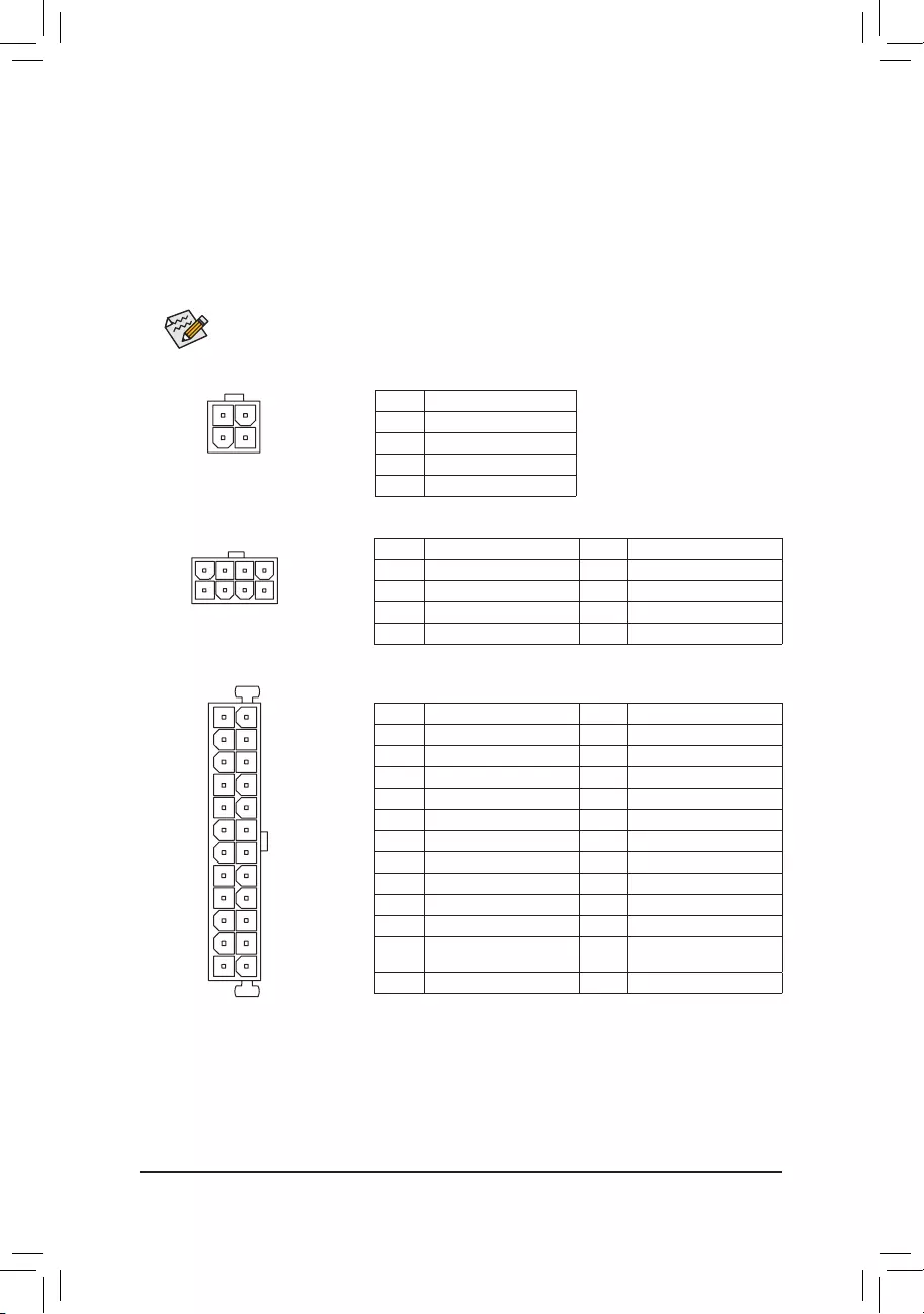
1/2) ATX_12V_2X2/ATX_12V_2X4/ATX (2×2, 2×4, 12V Power Connectors and 2×12 Main Power
Connector)
With the use of the power connector, the power supply can supply enough stable power to all the components
on the motherboard. Before connecting the power connector, rst make sure the power supply is turned off and
all devices are properly installed. The power connector possesses a foolproof design. Connect the power
supply cable to the power connector in the correct orientation.
The 12V power connector mainly supplies power to the CPU. If the 12V power connector is not connected,
the computer will not start.
To meet expansion requirements, it is recommended that a power supply that can withstand high
power consumption be used (500W or greater). If a power supply is used that does not provide the
required power, the result can lead to an unstable or unbootable system.
ATX:
Pin No. Denition Pin No. Denition
1 3.3V 13 3.3V
2 3.3V 14 -12V
3 GND 15 GND
4 +5V 16 PS_ON (soft On/Off)
5 GND 17 GND
6 +5V 18 GND
7 GND 19 GND
8 Power Good 20 NC
9 5VSB (stand by +5V) 21 +5V
10 +12V 22 +5V
11 +12V (Only for 2×12-pin
ATX)
23 +5V (Only for 2×12-pin ATX)
12 3.3V (Only for 2×12-pin ATX) 24 GND (Only for 2×12-pin ATX)
ATX_12V_2X4:
Pin No. Denition Pin No. Denition
1 GND (Only for 2×4-pin 12V) 5 +12V (Only for 2×4-pin 12V)
2 GND (Only for 2×4-pin 12V) 6 +12V (Only for 2×4-pin 12V)
3 GND 7 +12V
4 GND 8 +12V
ATX_12V_2X4
41
85
ATX_12V_2X2:
Pin No. Denition
1 GND
2 GND
3 +12V
4 +12V
ATX_12V_2X2
3 4
21
— 14 —
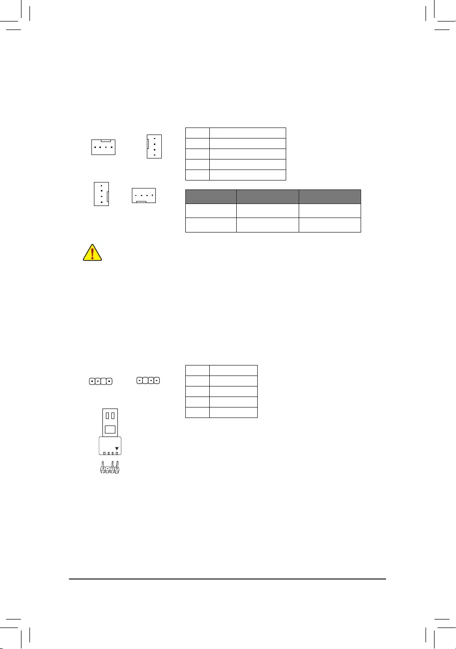
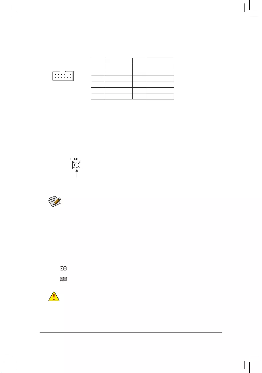
3/4) CPU_FAN/SYS_FAN1/2/3/4 (Fan Headers)
All fan headers on this motherboard are 4-pin. Most fan headers possess a foolproof insertion design.
When connecting a fan cable, be sure to connect it in the correct orientation (the black connector wire is
the ground wire). The speed control function requires the use of a fan with fan speed control design. For
optimum heat dissipation, it is recommended that a system fan be installed inside the chassis.
•Be sure to connect fan cables to the fan headers to prevent your CPU and system from
overheating. Overheating may result in damage to the CPU or the system may hang.
•These fan headers are not conguration jumper blocks. Do not place a jumper cap on the headers.
CPU_FAN/SYS_FAN2
1
1
SYS_FAN3 SYS_FAN4
1
Pin No. Denition
1 GND
2 Voltage Speed Control
3 Sense
4 PWM Speed Control
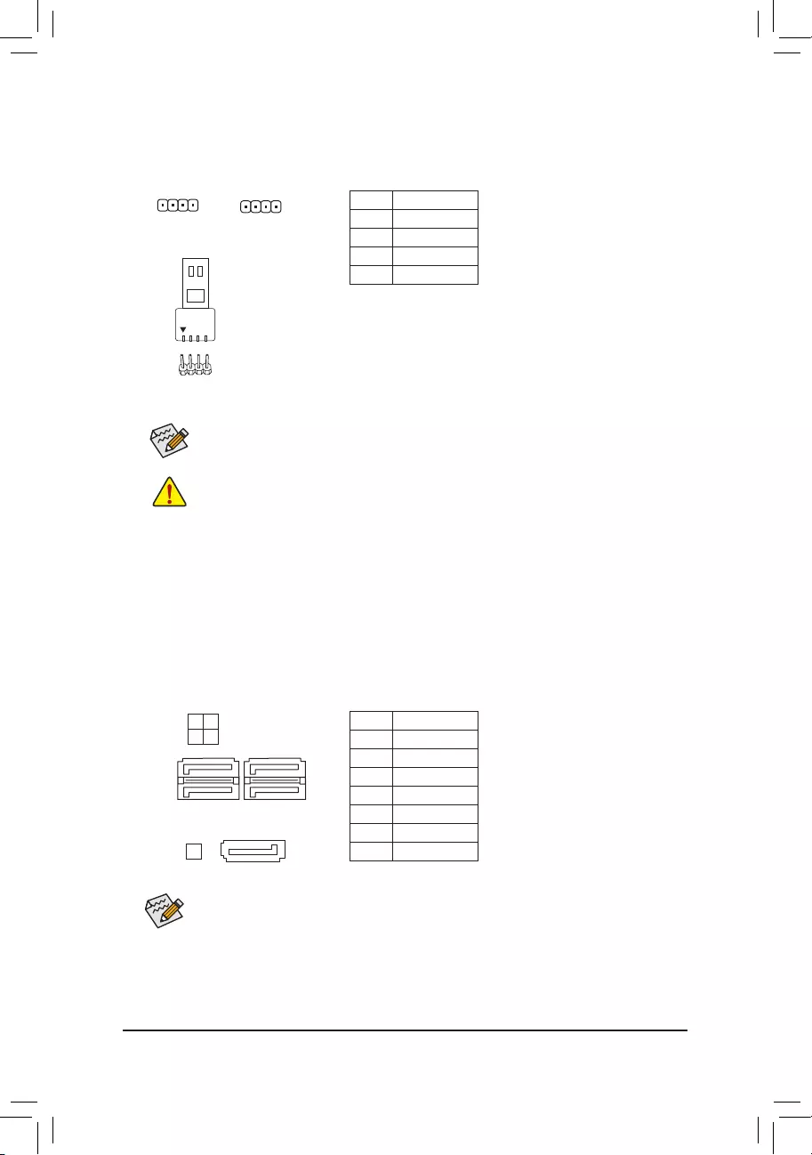
5) D_LED1/D_LED2 (Addressable LED Strip Headers)
The headers can be used to connect a standard 5050 addressable LED strip, with maximum power rating
of 5A (5V) and maximum number of 1000 LEDs.
Pin No. Denition
1 V (5V)
2 Data
3 No Pin
4 GND
1
F_USB30 F_U
B_
F_ F_
_
B
BS_
B
SB_
B
_S
S_
_
B
_U
_
B
S
123
123
123
123
1
1
1
1
BSS
S
_S
SSU
1 2 3
S3 BSSS
U
__ 3
F_USB3F
S _
S _
S _
SF
B_
B_
F
_0
S
S
_0F
_F
_
_
__B
U
S _S
_ SF_
B
USB0_B
B_
B_
F_USB3
F_USB303
_
_3U
S_
D_LED1 D_LED2
Connect your addressable LED strip to the header. The power pin
(marked with a triangle on the plug) of the LED strip must be connected
to Pin 1 of the addressable LED strip header. Incorrect connection may
lead to the damage of the LED strip.
Addressable LED
Strip
1
1
SYS_FAN1
1
F_USB30 F_U
B_
F_ F_
_
B
BS_
B
SB_
B
_S
S_
_
B
_U
_
B
S
123
123
123
123
1
1
1
1
BSS
S
_S
SSU
1 2 3
S3 BSSS
U
__ 3
F_USB3F
S _
S _
S _
SF
B_
B_
F
_0
S
S
_0F
_F
_
_
__B
U
S _S
_ SF_
B
USB0_B
B_
B_
F_USB3
F_USB303
_
_3U
S_
Connector CPU_FAN SYS_FAN1~4
Maximum Current 2A 2A
Maximum Power 24W 24W
— 15 —
6) LED_C1/LED_C2 (RGB LED Strip Headers)
The headers can be used to connect a standard 5050 RGB LED strip (12V/G/R/B), with maximum power
rating of 2A (12V) and maximum length of 2m.
Pin No. Denition
1 12V
2 G
3 R
4 B
Before installing the devices, be sure to turn off the devices and your computer. Unplug the power
cord from the power outlet to prevent damage to the devices.
1
Connect your RGB LED strip to the header. The power pin (marked
with a triangle on the plug) of the LED strip must be connected to
Pin 1 (12V) of this header. Incorrect connection may lead to the
damage of the LED strip.
For how to turn on/off the lights of the LED strip please visit the «Unique Features» webpage of
GIGABYTE’s website.
LED_C2
1
LED_C1
RGB LED Strip
1
12V
7) SATA3 1/2/3/4/5 (SATA 6Gb/s Connectors)
The SATA connectors conform to SATA 6Gb/s standard and are compatible with SATA 3Gb/s and SATA
1.5Gb/s standard. Each SATA connector supports a single SATA device. The Intel® Chipset supports RAID 0,
RAID 1, RAID 5, and RAID 10. Refer to Chapter 3, «Conguring a RAID Set,» for instructions on conguring
a RAID array.
Pin No. Denition
1 GND
2 TXP
3 TXN
4 GND
5 RXN
6 RXP
7 GND
To enable hot-plugging for the SATA ports, refer to Chapter 2, «BIOS Setup,» «Settings\IO Ports\
SATA And RST Conguration,» for more information.
1
1
SATA3 4 2
3 1
7
7
17
SATA3 5
— 16 —
F_USB30 F_U
B_
F_ F_
_
B
BS_
B
SB_
B
_S
S_
_
B
_U
_
B
S
123
123
123
123
1
1
1
1
BSS
S
_S
SSU
1 2 3
S3 BSSS
U
__ 3
F_USB3F
S _
S _
S _
SF
B_
B_
F
_0
S
S
_0F
_F
_
_
__B
U
S _S
_ SF_
B
USB0_B
B_
B_
F_USB3
F_USB303
_
_3U
S_
F_USB30 F_U
B_
F_ F_
_
B
BS_
B
SB_
B
_S
S_
_
B
_U
_
B
S
123
123
123
123
1
1
1
1
BSS
S
_S
SSU
1 2 3
S3 BSSS
U
__ 3
F_USB3F
S _
S _
S _
SF
B_
B_
F
_0
S
S
_0F
_F
_
_
__B
U
S _S
_ SF_
B
USB0_B
B_
B_
F_USB3
F_USB303
_
_3U
S_
M2P_CPU
(Note) /M2A_SB/M2M_SB (M.2 Socket 3 Connectors)
The M.2 connectors support M.2 SATA SSDs or M.2 PCIe SSDs and support RAID conguration. Please
note that an M.2 PCIe SSD cannot be used to create a RAID set either with an M.2 SATA SSD or a SATA
hard drive. Refer to Chapter 3, «Conguring a RAID Set,» for instructions on conguring a RAID array.
M2P_CPU (Note)
F_USB30 F_U
B_
F_ F_
_
B
BS_
B
SB_
B
_S
S_
_
B
_U
_
B
S
123
123
123
123
1
1
1
1
BSS
S
_S
SSU
1 2 3
S3 BSSS
U
__ 3
F_USB3F
S _
S _
S _
SF
B_
B_
F
_0
S
S
_0F
_F
_
_
__B
U
S _S
_ SF_
B
USB0_B
B_
B_
F_USB3
F_USB303
_
_3U
S_
80 60
M2A_SB
110
80 60110
80 60110
M2M_SB
(Note) Supported by 11th Generation processors only. Be sure to use Intel® SSDs if you want to set up a
RAID conguration on the M2P_CPU connector.
Follow the steps below to correctly install an M.2 SSD in the M.2 connector.
Step 1:
Locate the M.2 connector where you will install the M.2 SSD, use a screwdriver to unfasten the screw on
the heatsink and then remove the heatsink. (Only the M2P_CPU connector has the heatsink.) Remove the
protective lm from the thermal pad on the M.2 connector.
Step 2:
Locate the proper mounting hole based on the length of your M.2 SSD drive. If needed, move the standoff
to the desired mounting hole. Insert the M.2 SSD into the M.2 connector at an angle.
Step 3:
Press the M.2 SSD down and then use the included screw to secure it in the connector. Replace the heatsink
and secure it to the original hole. Remove the protective lm from the bottom of the heatsink before replacing
the heatsink.
— 17 —
•M2A_SB:
SATA3 1 SATA3 2 SATA3 3 SATA3 4 SATA3 5
M.2 SATA SSD ra a a a
M.2 PCIe SSD
aaaaa
No M.2 SSD Installed aaaaa
a: Available, r: Not available
Connector
Type of M.2
SSD
Installation Notices for the M.2 and SATA Connectors:
The availability of the SATA connectors may be affected by the type of device installed in the M.2 sockets. The
M2A_SB connector shares bandwidth with the SATA3 1 connector. Refer to the following tables for details.
•M2M_SB:
SATA3 1 SATA3 2 SATA3 3 SATA3 4 SATA3 5
M.2 PCIe SSD *
aaaaa
No M.2 SSD Installed aaaaa
a: Available, r: Not available
* The M2M_SB connector supports only PCIe SSDs.
Connector
Type of M.2
SSD
•M2P_CPU (Note):
SATA3 1 SATA3 2 SATA3 3 SATA3 4 SATA3 5
M.2 PCIe SSD
aaaaa
No M.2 SSD Installed aaaaa
a: Available, r: Not available
* The M2P_CPU connector supports only PCIe SSDs.
Connector
Type of M.2
SSD
(Note) Supported by 11th Generation processors only.
— 18 —
The front panel design may differ by chassis. A front panel module mainly consists of power switch, reset
switch, power LED, hard drive activity LED, speaker and etc. When connecting your chassis front panel
module to this header, make sure the wire assignments and the pin assignments are matched correctly.
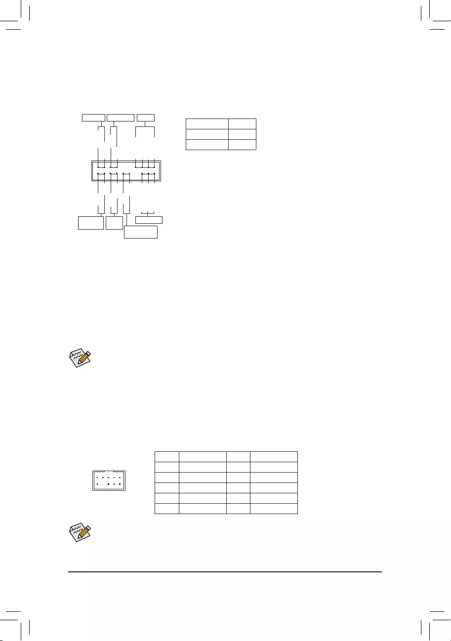
9) F_PANEL (Front Panel Header)
Connect the power switch, reset switch, speaker, chassis intrusion switch/sensor and system status indicator
on the chassis to this header according to the pin assignments below. Note the positive and negative pins
before connecting the cables.
System Status LED
S0 On
S3/S4/S5 Off
•PW (Power Switch, Red):
Connects to the power switch on the chassis front panel. You may
congure the way to turn off your system using the power switch
(refer to Chapter 2, «BIOS Setup,» «Settings\Platform Power,» for more
information).
•SPEAK (Speaker, Orange):
Connects to the speaker on the chassis front panel. The system reports
system startup status by issuing a beep code. One single short beep
will be heard if no problem is detected at system startup.
•PLED/PWR_LED (Power LED, Yellow/Purple):
Connects to the power status indicator
on the chassis front panel. The LED is on
when the system is operating. The LED is
off when the system is in S3/S4 sleep state
or powered off (S5).
•HD (Hard Drive Activity LED, Blue):
Connects to the hard drive activity LED on the chassis front panel. The LED is on when the hard drive
is reading or writing data.
•RES (Reset Switch, Green):
Connects to the reset switch on the chassis front panel. Press the reset switch to restart the computer
if the computer freezes and fails to perform a normal restart.
•CI (Chassis Intrusion Header, Gray):
Connects to the chassis intrusion switch/sensor on the chassis that can detect if the chassis cover has
been removed. This function requires a chassis with a chassis intrusion switch/sensor.
•NC (Orange): No Connection.
Power LED
1
2
19
20
CI-
CI+
PWR_LED-
PWR_LED+
PLED-
PW-
SPEAK+
SPEAK-
PLED+
PW+
Power LED
HD-
RES+
HD+
RES-
Hard Drive
Activity LED
Reset
Switch Chassis Intrusion
Header
Power Switch Speaker
PWR_LED-
NC
NC
10) F_AUDIO (Front Panel Audio Header)
The front panel audio header supports High Denition audio (HD). You may connect your chassis front
panel audio module to this header. Make sure the wire assignments of the module connector match the
pin assignments of the motherboard header. Incorrect connection between the module connector and the
motherboard header will make the device unable to work or even damage it.
Some chassis provide a front panel audio module that has separated connectors on each wire instead
of a single plug. For information about connecting the front panel audio module that has different wire
assignments, please contact the chassis manufacturer.
F_USB30 F_U
B_
F_ F_
_
B
BS_
B
SB_
B
_S
S_
_
B
_U
_
B
S
123
123
123
123
1
1
1
1
BSS
S
_S
SSU
1 2 3
S3 BSSS
U
__ 3
F_USB3F
S _
S _
S _
SF
B_
B_
F
_0
S
S
_0F
_F
_
_
__B
U
S _S
_ SF_
B
USB0_B
B_
B_
F_USB3
F_USB303
_
_3U
S_
9 1
10 2
Pin No. Denition Pin No. Denition
1 MIC2_L 6 Sense
2 GND 7 FAUDIO_JD
3 MIC2_R 8 No Pin
4 NC 9 LINE2_L
5 LINE2_R 10 Sense
— 19 —
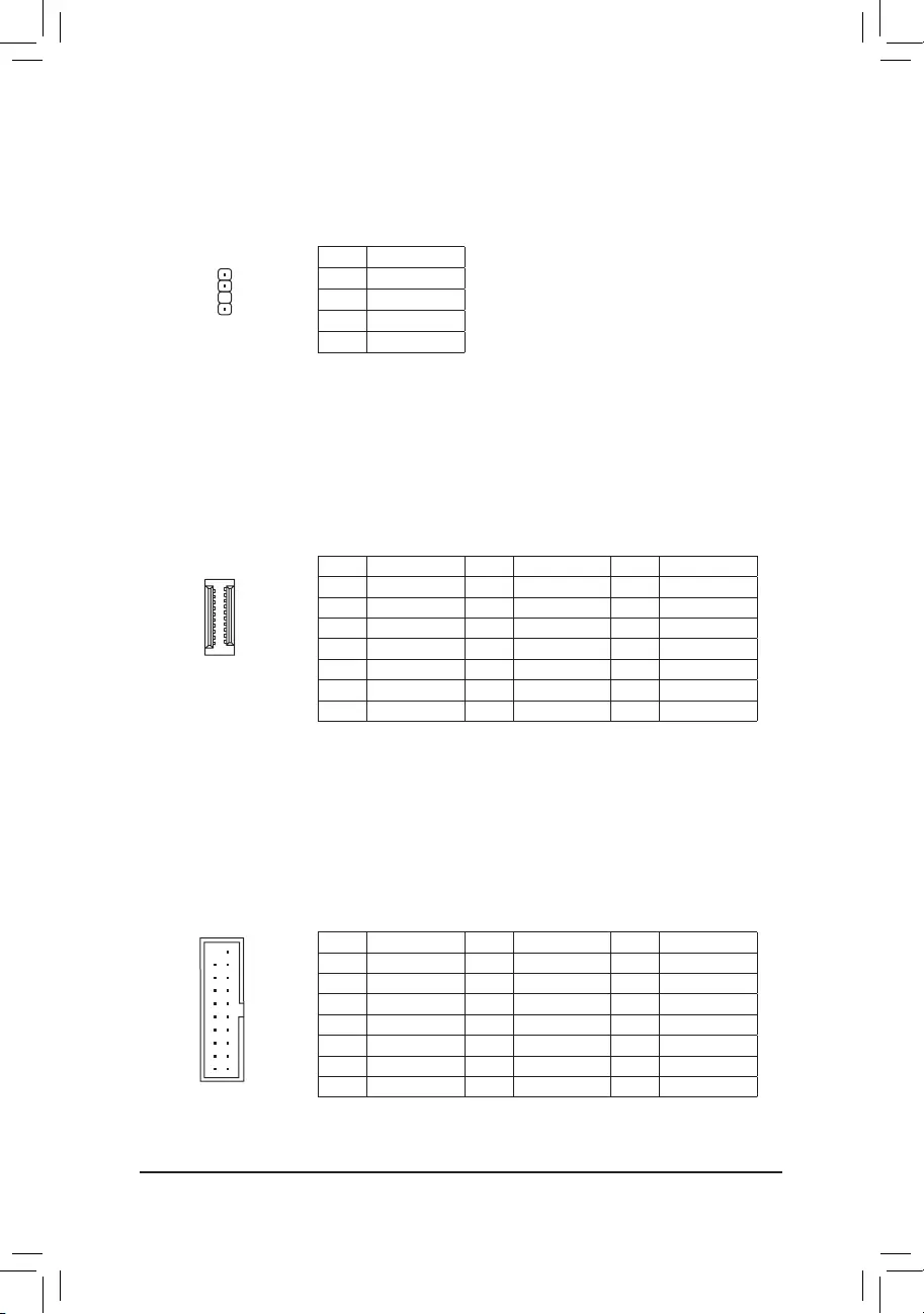
11) SPDIF_O (S/PDIF Out Header)
This header supports S/PDIF digital output, which allows you to connect a S/PDIF digital audio cable to
output digital audio from your motherboard to the supported audio devices. For information about connecting
the digital audio cable, carefully read the manual for your audio devices.
Pin No. Denition
1 5VDUAL
2 No Pin
3 SPDIFO
4 GND
1
F_USB30 F_U
B_
F_ F_
_
B
BS_
B
SB_
B
_S
S_
_
B
_U
_
B
S
123
123
123
123
1
1
1
1
BSS
S
_S
SSU
1 2 3
S3 BSSS
U
__ 3
F_USB3F
S _
S _
S _
SF
B_
B_
F
_0
S
S
_0F
_F
_
_
__B
U
S _S
_ SF_
B
USB0_B
B_
B_
F_USB3
F_USB303
_
_3U
S_
Pin No. Denition Pin No. Denition Pin No. Denition
1 VBUS 8 D1- 15 SSTX2-
2 SSRX1- 9 D1+ 16 GND
3 SSRX1+ 10 NC 17 SSRX2+
4 GND 11 D2+ 18 SSRX2-
5 SSTX1- 12 D2- 19 VBUS
6 SSTX1+ 13 GND 20 No Pin
7 GND 14 SSTX2+
13) F_U32 (USB 3.2 Gen 1 Header)
The header conforms to USB 3.2 Gen 1 and USB 2.0 specication and can provide two USB ports. For
purchasing the optional 3.5″ front panel that provides two USB 3.2 Gen 1 ports, please contact the local
dealer.
F_USB30 F_U
B_
F_ F_
_
B
BS_
B
SB_
B
_S
S_
_
B
_U
_
B
S
123
123
123
123
1
1
1
1
BSS
S
_S
SSU
1 2 3
S3 BSSS
U
__ 3
F_USB3F
S _
S _
S _
SF
B_
B_
F
_0
S
S
_0F
_F
_
_
__B
U
S _S
_ SF_
B
USB0_B
B_
B_
F_USB3
F_USB303
_
_3U
S_
10
20 1
11
F_USB30 F_U
B_
F_ F_
_
B
BS_
B
SB_
B
_S
S_
_
B
_U
_
B
S
123
123
123
123
1
1
1
1
BSS
S
_S
SSU
1 2 3
S3 BSSS
U
__ 3
F_USB3F
S _
S _
S _
SF
B_
B_
F
_0
S
S
_0F
_F
_
_
__B
U
S _S
_ SF_
B
USB0_B
B_
B_
F_USB3
F_USB303
_
_3U
S_
12) F_U32C (USB Type-C® Header with USB 3.2 Gen 1 Support)
The header conforms to USB 3.2 Gen 1 specication and can provide one USB port.
Pin No. Denition Pin No. Denition Pin No. Denition
1 VBUS 8 CC1 15 RX2+
2 TX1+ 9 SBU1 16 RX2-
3 TX1- 10 SBU2 17 GND
4 GND 11 VBUS 18 D-
5 RX1+ 12 TX2+ 19 D+
6 RX1- 13 TX2- 20 CC2
7 VBUS 14 GND
20
10 11
1
— 20 —
14) F_USB1/F_USB2 (USB 2.0/1.1 Headers)
The header conforms to USB 2.0/1.1 specication. Each USB header can provide two USB ports via an
optional USB bracket. For purchasing the optional USB bracket, please contact the local dealer.
Pin No. Denition Pin No. Denition
1 Power (5V) 6 USB DY+
2 Power (5V) 7 GND
3 USB DX- 8 GND
4 USB DY— 9 No Pin
5 USB DX+ 10 NC
•Do not plug the IEEE 1394 bracket (2×5-pin) cable into the USB 2.0/1.1 header.
•Prior to installing the USB bracket, be sure to turn off your computer and unplug the power cord
from the power outlet to prevent damage to the USB bracket.
10
9
2
1
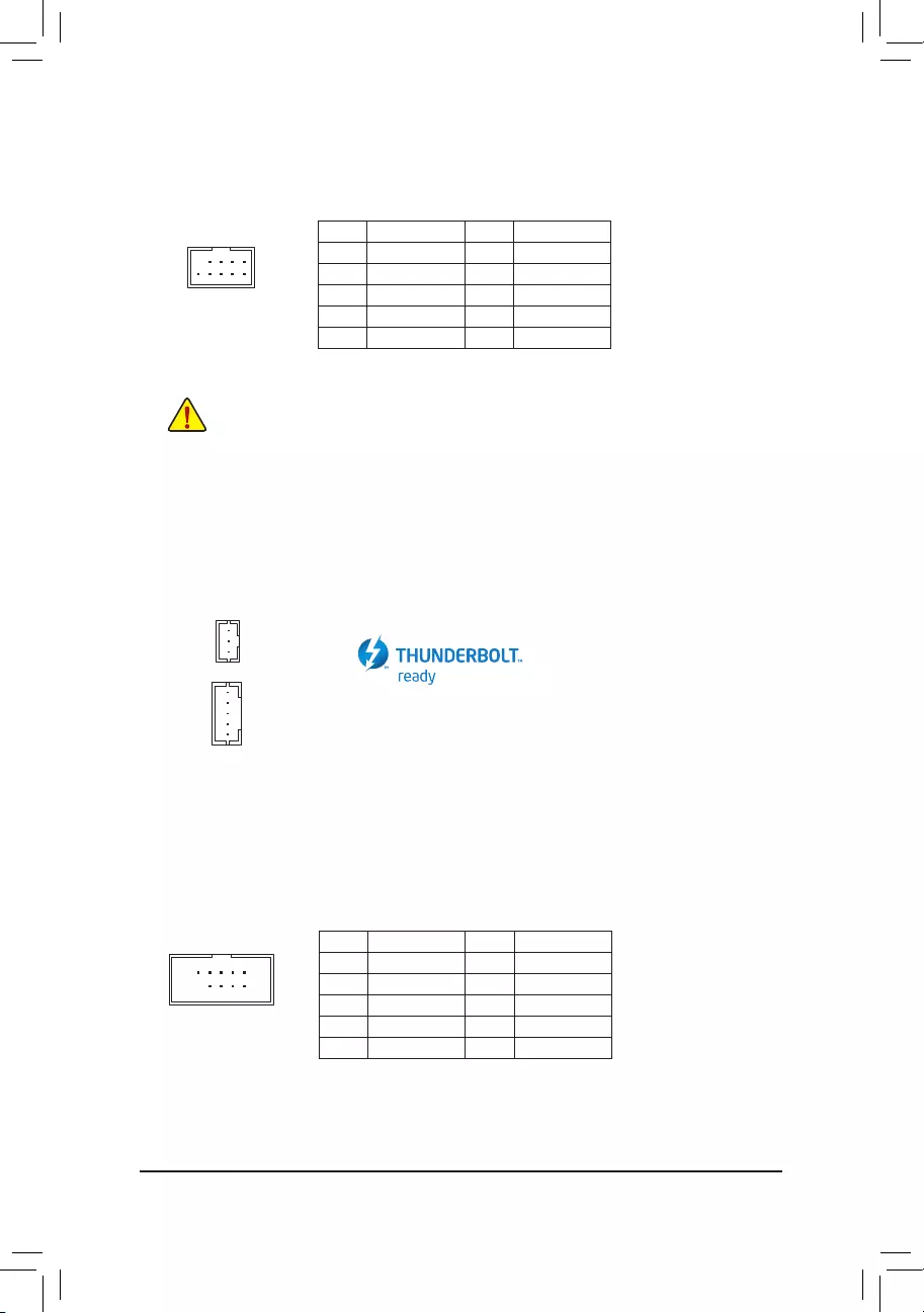
15) THB_C1/THB_C2 (Thunderbolt™ Add-in Card Connectors)
The connectors are used to connect to a GIGABYTE Thunderbolt™ add-in card.
Supports a Thunderbolt™ add-in card.
10
9
2
1
16) COM (Serial Port Header)
The COM header can provide one serial port via an optional COM port cable. For purchasing the optional
COM port cable, please contact the local dealer.
Pin No. Denition Pin No. Denition
1 NDCD- 6 NDSR-
2 NSIN 7 NRTS-
3 NSOUT 8 NCTS-
4 NDTR- 9 NRI-
5 GND 10 No Pin
F_USB30 F_U
B_
F_ F_
_
B
BS_
B
SB_
B
_S
S_
_
B
_U
_
B
S
123
123
123
123
1
1
1
1
BSS
S
_S
SSU
1 2 3
S3 BSSS
U
__ 3
F_USB3F
S _
S _
S _
SF
B_
B_
F
_0
S
S
_0F
_F
_
_
__B
U
S _S
_ SF_
B
USB0_B
B_
B_
F_USB3
F_USB303
_
_3U
S_
1
F_USB30 F_U
B_
F_ F_
_
B
BS_
B
SB_
B
_S
S_
_
B
_U
_
B
S
123
123
123
123
1
1
1
1
BSS
S
_S
SSU
1 2 3
S3 BSSS
U
__ 3
F_USB3F
S _
S _
S _
SF
B_
B_
F
_0
S
S
_0F
_F
_
_
__B
U
S _S
_ SF_
B
USB0_B
B_
B_
F_USB3
F_USB303
_
_3U
S_
1
THB_C2
THB_C1
— 21 —
12
11
2
1
17) SPI_TPM (Trusted Platform Module Header)
You may connect an SPI TPM (Trusted Platform Module) to this header.
Pin No. Denition Pin No. Denition
1Data Output 7Chip Select
2Power (3.3V) 8GND
3No Pin 9IRQ
4NC 10 NC
5Data Input 11 NC
6CLK 12 RST
F_USB30 F_U
B_
F_ F_
_
B
BS_
B
SB_
B
_S
S_
_
B
_U
_
B
S
123
123
123
123
1
1
1
1
BSS
S
_S
SSU
1 2 3
S3 BSSS
U
__ 3
F_USB3F
S _
S _
S _
SF
B_
B_
F
_0
S
S
_0F
_F
_
_
__B
U
S _S
_ SF_
B
USB0_B
B_
B_
F_USB3
F_USB303
_
_3U
S_
18) QFLASH_PLUS (Q-Flash Plus Button)
Q-Flash Plus allows you to update the BIOS when your system is off (S5 shutdown state). Save the latest
BIOS on a USB thumb drive and plug it into the dedicated port, and then you can now ash the BIOS
automatically by simply pressing the Q-Flash Plus button. The QFLED will ash when the BIOS matching
and ashing activities start and will stop ashing when the main BIOS ashing is complete.
For how to use Q-Flash Plus please visit the «Unique Features» webpage of GIGABYTE’s website.
QFLASH_PLUS
QFLED
19) CLR_CMOS (Clear CMOS Jumper)
Use this jumper to clear the BIOS conguration and reset the CMOS values to factory defaults. To clear
the CMOS values, use a metal object like a screwdriver to touch the two pins for a few seconds.
•Always turn off your computer and unplug the power cord from the power outlet before clearing
the CMOS values.
•After system restart, go to BIOS Setup to load factory defaults (select Load Optimized Defaults) or
manually congure the BIOS settings (refer to Chapter 2, «BIOS Setup,» for BIOS congurations).
Open: Normal
Short: Clear CMOS Values
— 22 —
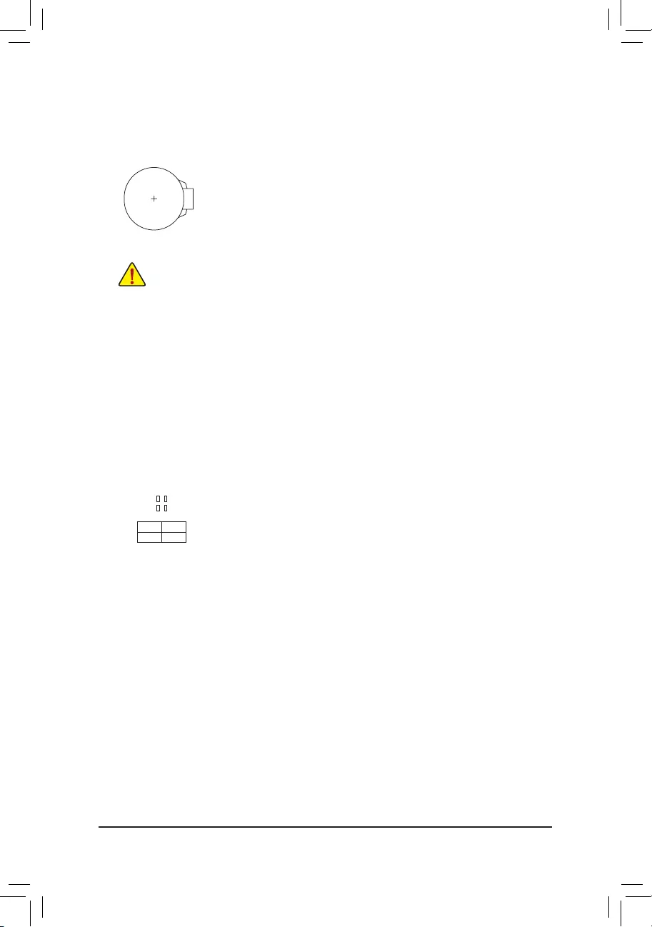
20) BAT (Battery)
The battery provides power to keep the values (such as BIOS congurations, date, and time information)
in the CMOS when the computer is turned off. Replace the battery when the battery voltage drops to a low
level, or the CMOS values may not be accurate or may be lost.
You may clear the CMOS values by removing the battery:
1. Turn off your computer and unplug the power cord.
2. Gently remove the battery from the battery holder and wait for one minute. (Or use a metal
object like a screwdriver to touch the positive and negative terminals of the battery holder,
making them short for 5 seconds.)
3. Replace the battery.
4. Plug in the power cord and restart your computer.
•Always turn off your computer and unplug the power cord before replacing the battery.
•Replace the battery with an equivalent one. Damage to your devices may occur if the battery is
replaced with an incorrect model.
•Contact the place of purchase or local dealer if you are not able to replace the battery by yourself
or uncertain about the battery model.
•When installing the battery, note the orientation of the positive side (+) and the negative side (-)
of the battery (the positive side should face up).
•Used batteries must be handled in accordance with local environmental regulations.
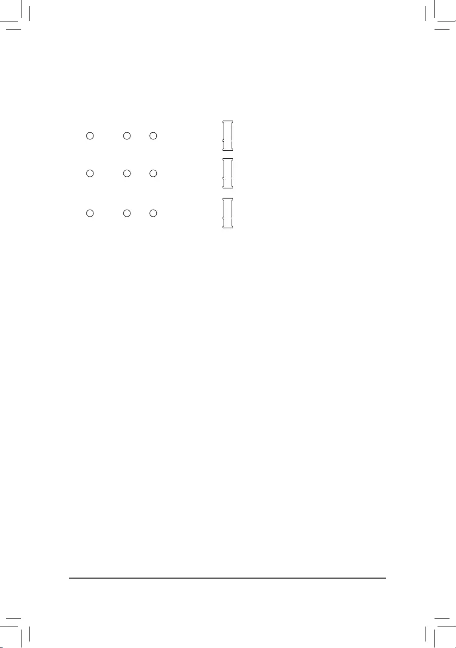
21) CPU/DRAM/VGA/BOOT (Status LEDs)
The status LEDs show whether the CPU, memory, graphics card, and operating system are working
properly after system power-on. If the CPU/DRAM/VGA LED is on, that means the corresponding device
is not working normally; if the BOOT LED is on, that means you haven’t entered the operating system yet.
CPU: CPU status LED
DRAM: Memory status LED
VGA: Graphics card status LED
BOOT: Operating system status LED
F_USB30 F_U
B_
F_ F_
_
B
BS_
B
SB_
B
_S
S_
_
B
_U
_
B
S
123
123
123
123
1
1
1
1
BSS
S
_S
SSU
1 2 3
S3 BSSS
U
__ 3
F_USB3F
S _
S _
S _
SF
B_
B_
F
_0
S
S
_0F
_F
_
_
__B
U
S _S
_ SF_
B
USB0_B
B_
B_
F_USB3
F_USB303
_
_3U
S_
— 23 —
CPU DRAM
VGA BOOT
BIOS (Basic Input and Output System) records hardware parameters of the system in the CMOS on the
motherboard. Its major functions include conducting the Power-On Self-Test (POST) during system startup,
saving system parameters and loading operating system, etc. BIOS includes a BIOS Setup program that allows
the user to modify basic system conguration settings or to activate certain system features.
When the power is turned off, the battery on the motherboard supplies the necessary power to the CMOS to
keep the conguration values in the CMOS.
To access the BIOS Setup program, press the <Delete> key during the POST when the power is turned on.
To upgrade the BIOS, use either the GIGABYTE Q-Flash or @BIOS utility.
•Q-Flash allows the user to quickly and easily upgrade or back up BIOS without entering the operating system.
•@BIOS is a Windows-based utility that searches and downloads the latest version of BIOS from the Internet
and updates the BIOS.
Chapter 2 BIOS Setup
•Because BIOS ashing is potentially risky, if you do not encounter problems using the current version of BIOS,
it is recommended that you not ash the BIOS. To ash the BIOS, do it with caution. Inadequate BIOS ashing
may result in system malfunction.
•It is recommended that you not alter the default settings (unless you need to) to prevent system instability or other
unexpected results. Inadequately altering the settings may result in system’s failure to boot. If this occurs, try to
clear the CMOS values and reset the board to default values. (Refer to the «Load Optimized Defaults» section in
this chapter or introductions of the battery/clear CMOS jumper in Chapter 1 for how to clear the CMOS values.)
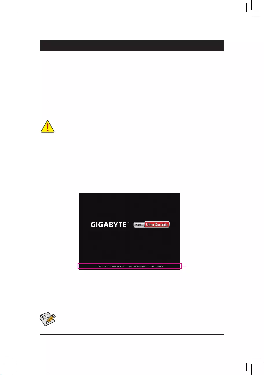
2-1 Startup Screen
The following startup Logo screen will appear when the computer boots.
•When the system is not stable as usual, select the Load Optimized Defaults item to set your system to its defaults.
•The BIOS Setup menus described in this chapter are for reference only and may differ by BIOS version.
Function Keys
There are two different BIOS modes as follows and you can use the <F2> key to switch between the two modes.
Easy Mode allows users to quickly view their current system information or to make adjustments for optimum
performance. In Easy Mode, you can use your mouse to move through conguration items. The Advanced Mode
provides detailed BIOS settings. You can press the arrow keys on your keyboard to move among the items
and press <Enter> to accept or enter a sub-menu. Or you can use your mouse to select the item you want.
— 24 —

2-2 The Main Menu
Hardware
Information
Conguration Items Current Settings
Setup Menus
Conguration
Items
System Time
Quick Access Bar allows you to quickly move to
the General Help, Easy Mode, Smart Fan 6, or
Q-Flash screen.
Advanced Mode Function Keys
<f><g>Move the selection bar to select a setup menu
<h><i>Move the selection bar to select an conguration item on a menu
<Enter>/Double Click Execute command or enter a menu
<+>/<Page Up> Increase the numeric value or make changes
<->/<Page Down> Decrease the numeric value or make changes
<F1> Show descriptions of the function keys
<F2> Switch to Easy Mode
<F3> Save the current BIOS settings to a prole
<F4> Load the BIOS settings from a prole created before
<F5> Restore the previous BIOS settings for the current submenus
<F6> Display the Smart Fan 6 screen
<F7> Load the Optimized BIOS default settings for the current submenus
<F8> Access the Q-Flash utility
<F10> Save all the changes and exit the BIOS Setup program
<F11> Switch to the Favorites submenu
<F12> Capture the current screen as an image and save it to your USB drive
<Insert> Add or remove a favorite option
<Ctrl>+<S> Display information on the installed memory
<Esc> Main Menu: Exit the BIOS Setup program
Submenus: Exit current submenu
— 25 —
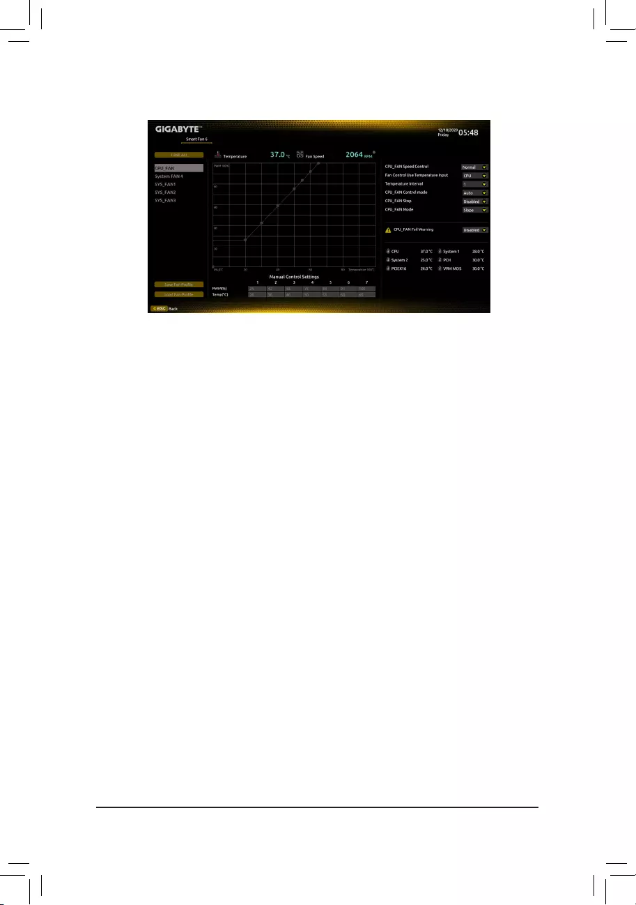
Use the <F6> function key to quickly switch to this screen. This screen allows you to congure fan speed related
settings for each fan header or monitor your system/CPU temperature.
&TUNE ALL
Allows you to apply the current settings to all fan headers.
&Temperature
Displays the current temperature of the selected target area.
&Fan Speed
Displays current fan/pump speeds.
&Flow Rate
Displays the ow rate of your water cooling system. Press <Enter> on Fan Speed to switch to this function.
&Fan Speed Control
Allows you to determine whether to enable the fan speed control function and adjust the fan speed.
Normal Allows the fan to run at different speeds according to the temperature. You can adjust
the fan speed with System Information Viewer based on your system requirements.
(Default)
Silent Allows the fan to run at slow speeds.
Manual Allows you to drag the curve nodes to adjust fan speed. Or you can use the EZ Tuning
feature. After adjusting the node position, press Apply to automatically calculate the
slope of the curve.
Full Speed Allows the fan to run at full speeds.
&Fan Control Use Temperature Input
Allows you to select the reference temperature for fan speed control.
&Temperature Interval
Allows you to select the temperature interval for fan speed change.
&FAN Control Mode
Auto Lets the BIOS automatically detect the type of fan installed and sets the optimal control
mode. (Default)
Voltage Voltage mode is recommended for a 3-pin fan.
PWM PWM mode is recommended for a 4-pin fan.
&FAN Stop
Enables or disables the fan stop function. You can set the temperature limit using the temperature curve.
The fan stops operation when the temperature is lower than the limit. (Default: Disabled)
2-3 Smart Fan 6
— 26 —
&FAN Mode
Allows you to set the operating mode for the fan.
Slope Adjusts the fan speed linearly based on the temperature. (Default)
Stair Adjusts the fan speed stepwise based on the temperature.
&FAN Fail Warning
Allows the system to emit warning sound if the fan is not connected or fails. Check the fan condition or fan
connection when this occurs. (Default: Disabled)
&SaveFanProle
This function allows you to save the current settings to a prole. You can save the prole in the BIOS or
select Select File in HDD/FDD/USB to save the prole to your storage device.
&LoadFanProle
This function allows you to load a previously saved BIOS prole without the hassles of reconguring the
BIOS settings. Or you can select Select File in HDD/FDD/USB to load a prole from your storage device.
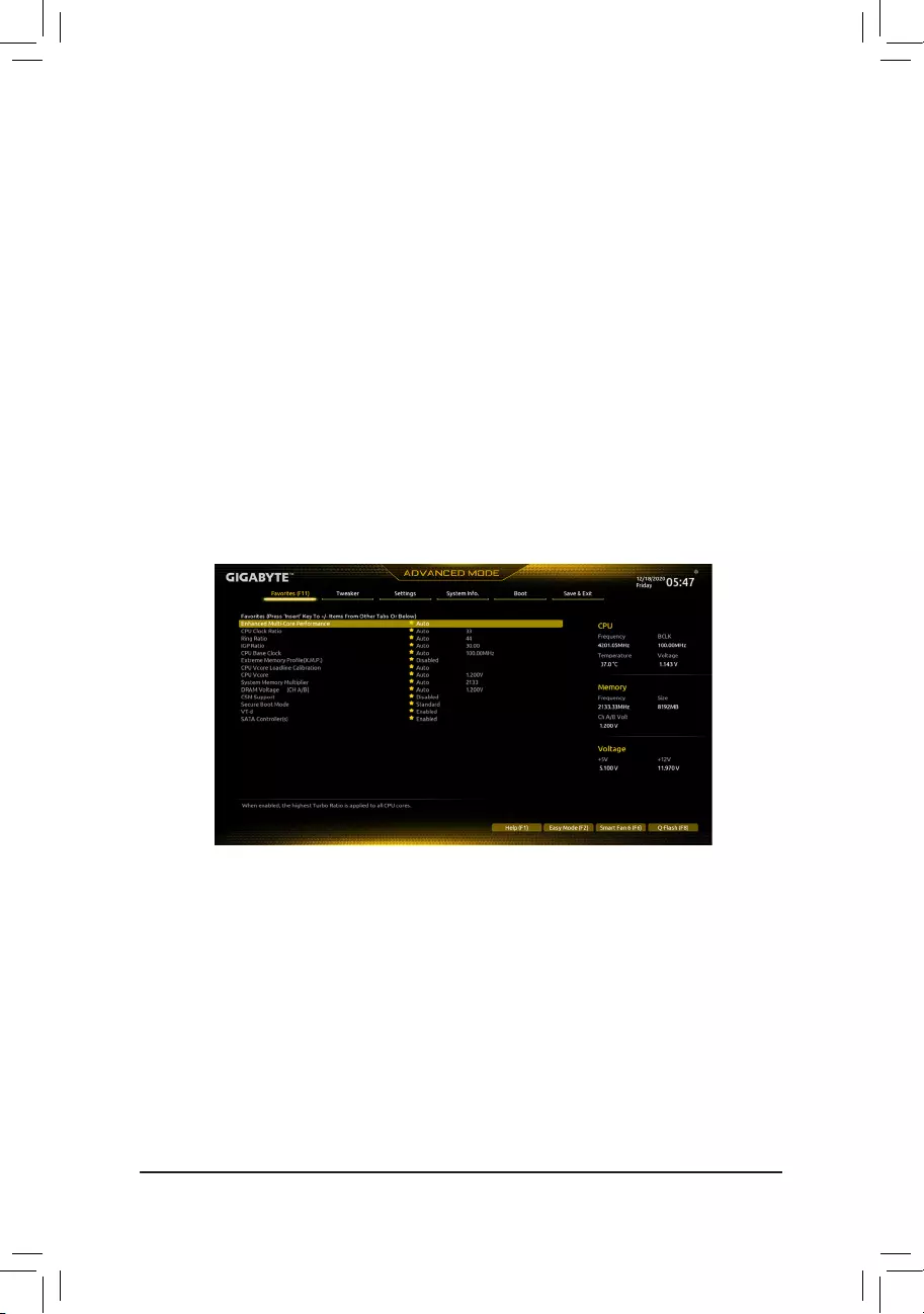
2-4 Favorites (F11)
Set your frequently used options as your favorites and use the <F11> key to quickly switch to the page where
all of your favorite options are located. To add or remove a favorite option, go to its original page and press
<Insert> on the option. The option is marked with a star sign if set as a «favorite.»
— 27 —
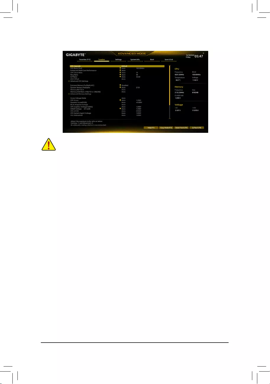
2-5 Tweaker
Whether the system will work stably with the overclock/overvoltage settings you made is dependent
on your overall system congurations. Incorrectly doing overclock/overvoltage may result in damage
to CPU, chipset, or memory and reduce the useful life of these components. This page is for advanced
users only and we recommend you not to alter the default settings to prevent system instability or
other unexpected results. (Inadequately altering the settings may result in system’s failure to boot. If
this occurs, clear the CMOS values and reset the board to default values.)
&CPU Upgrade
Allows you to set the CPU frequency. The nal result may vary depending on the CPU used. Options are:
Default, Gaming Prole, Advanced. (Default: Default)
&CPU Base Clock
Allows you to manually set the CPU base clock in 0.01 MHz increments. (Default: Auto)
Important: It is highly recommended that the CPU frequency be set in accordance with the CPU
specications.
&PVD Ratio Threshold Override (Note)
Allows you to determine whether to improve performance under extreme BCLK OC by reducing a “PLL
Banding” condition caused in part by a very high DCO frequency. (Default: Auto)
&Enhanced Multi-Core Performance
Determines whether to allow the CPU to run at Turbo 1C speed. (Default: Auto)
&CPU Clock Ratio
Allows you to alter the clock ratio for the installed CPU. The adjustable range is dependent on the CPU
being installed.
&Ring Ratio
Allows you to set the CPU Uncore ratio. The adjustable range is dependent on the CPU being used. (Default:
Auto)
&IGP Ratio (Note)
Allows you to set the Graphics Ratio. (Default: Auto)
&AVX Disable (Note)
Allows you to disable the AVX instruction sets on a CPU that supports AVX. (Default: Auto)
&AVX512 Disable (Note)
Allows you to disable the AVX-512 instruction sets on a CPU that supports AVX-512. (Default: Auto)
(Note) This item is present only when you install a CPU that supports this feature. For more information about
Intel® CPUs’ unique features, please visit Intel’s website.
— 28 —

&AVX Offset (Note)
When the processor runs AVX workloads, the CPU Clock Ratio will be reduced by the desired AVX offset
value. For example, if the value is set to 3, the CPU Clock Ratio will be reduced by 3 when executing AVX
instructions. (Default: Auto)
&AVX512 Offset (Note)
When the processor runs AVX-512 workloads, the CPU Clock Ratio will be reduced by the desired AVX-512
offset value. For example, if the value is set to 3 (the value must be larger than or equal to the AVX Offset
value), the CPU Clock Ratio will be reduced by 3 when executing AVX-512 instructions. (Default: Auto)
&AVX Voltage Guardband Scale Factor (Note)
Allows you to lower the standard AVX voltage. (Default: Auto)
&AVX512 Voltage Guardband Scale Factor (Note)
Allows you to lower the standard AVX-512 voltage. (Default: Auto)
Advanced CPU Settings
&Core Fused Max Core Ratio (Note)
Displays the highest frequency of each core.
&CPU Over Temperature Protection (Note)
Allows you to ne-tune the TJ Max offset value. (Default: Auto)
&FCLK Frequency for Early Power On (Note)
Allows you to set the FCLK frequency. Options are: Normal(800Mhz), 1GHz, 400MHz. (Default: 1GHz)
&Hyper-Threading Technology
Allows you to determine whether to enable multi-threading technology when using an Intel® CPU that
supports this function. This feature only works for operating systems that support multi-processor mode.
Auto lets the BIOS automatically congure this setting. (Default: Auto)
&No. of CPU Cores Enabled
Allows you to select the number of CPU cores to enable in an Intel® multi-core CPU (the number of CPU
cores may vary by CPU). Auto lets the BIOS automatically congure this setting. (Default: Auto)
&Intel(R) Speed Shift Technology (Intel® Speed Shift Technology) (Note)
Enables or disables Intel® Speed Shift Technology. Enabling this feature allows the processor to ramp up
its operating frequency more quickly and then improves the system responsiveness. (Default: Enabled)
&CPU Thermal Monitor (Note)
Enables or disables Intel® Thermal Monitor function, a CPU overheating protection function. When enabled,
the CPU core frequency and voltage will be reduced when the CPU is overheated. Auto lets the BIOS
automatically congure this setting. (Default: Auto)
&Ring to Core offset (Down Bin)
Allows you to determine whether to disable the CPU Ring ratio auto-down function. Auto lets the BIOS
automatically congure this setting. (Default: Auto)
&CPU EIST Function (Note)
Enables or disables Enhanced Intel® Speed Step Technology (EIST). Depending on CPU loading, Intel®
EIST technology can dynamically and effectively lower the CPU voltage and core frequency to decrease
average power consumption and heat production. Auto lets the BIOS automatically congure this setting.
(Default: Auto)
&Race To Halt (RTH) (Note)/EnergyEfcientTurbo (Note)
Enables or disables the CPU power saving related settings. (Default: Auto)
&Intel(R) Turbo Boost Technology (Note)
Allows you to determine whether to enable the Intel® CPU Turbo Boost technology. Auto lets the BIOS
automatically congure this setting. (Default: Auto)
(Note) This item is present only when you install a CPU that supports this feature. For more information about
Intel® CPUs’ unique features, please visit Intel’s website.
— 29 —

&Intel(R) Turbo Boost Max Technology 3.0 (Note)
Enables or disables Intel® Turbo Boost Max Technology 3.0. Intel® Turbo Boost Max Technology 3.0 allows
the system to identify the processor’s best performance core and lets you manually direct the most critical
workloads to it. You can even adjust the frequency of each core individually for performance optimization.
(Default: Enabled)
&CPU Flex Ratio Override
Enables or disables the CPU Flex Ratio. The maximum CPU clock ratio will be based on the CPU Flex
Ratio Settings value if CPU Clock Ratio is set to Auto. (Default: Disabled)
&CPU Flex Ratio Settings
Allows you to set the CPU Flex Ratio. The adjustable range may vary by CPU.
&Frequency Clipping TVB (Note)
Allows you to enable or disable automatic CPU frequency reduction initiated by Thermal Velocity Boost.
Auto lets the BIOS automatically congure this setting. (Default: Auto)
&Voltage reduction initiated TVB (Note)
Allows you to enable or disable automatic CPU voltage reduction initiated by Thermal Velocity Boost. Auto
lets the BIOS automatically congure this setting. (Default: Auto)
dActive Turbo Ratios
&Turbo Ratio (Core Active)
Allows you to set the CPU Turbo ratios for active cores. Auto sets the CPU Turbo ratios according to the
CPU specications.
This item is congurable only when
Active Turbo Ratios is set
to
Enabled
.
(Default:
Auto)
dPer Core HT Disable Setting
&HT Disable (Note)
Allows you determine whether to disable the HT feature for each CPU core. This item is congurable only
when Per Core HT Disable Setting is set to Manual. (Default: Disabled)
dC-States Control
&CPU Enhanced Halt (C1E)
Enables or disables Intel
®
CPU Enhanced Halt (C1E) function, a CPU power-saving function in system halt
state. When enabled, the CPU core frequency and voltage will be reduced during system halt state to decrease
power consumption. Auto lets the BIOS automatically congure this setting.
This item is congurable only
when
C-States is
enabled.
(Default: Auto)
&C3 State Support (Note)
Allows you to determine whether to let the CPU enter C3 mode in system halt state. When enabled, the
CPU core frequency and voltage will be reduced during system halt state to decrease power consumption.
The C3 state is a more enhanced power-saving state than C1. Auto lets the BIOS automatically congure
this setting. This item is congurable only when
C-States is
enabled.
(Default: Auto)
&C6/C7 State Support
Allows you to determine whether to let the CPU enter C6/C7 mode in system halt state. When enabled, the
CPU core frequency and voltage will be reduced during system halt state to decrease power consumption.
The C6/C7 state is a more enhanced power-saving state than C3. Auto lets the BIOS automatically congure
this setting. This item is congurable only when C-States Control is set to Enabled. (Default: Auto)
(Note) This item is present only when you install a CPU that supports this feature. For more information about
Intel® CPUs’ unique features, please visit Intel’s website.
— 30 —

&C8 State Support (Note 1)
Allows you to determine whether to let the CPU enter C8 mode in system halt state. When enabled, the CPU
core frequency and voltage will be reduced during system halt state to decrease power consumption. The
C8 state is a more enhanced power-saving state than C6/C7. Auto lets the BIOS automatically congure
this setting. This item is congurable only when C-States Control is set to Enabled. (Default: Auto)
&C10 State Support (Note 1)
Allows you to determine whether to let the CPU enter C10 mode in system halt state. When enabled, the
CPU core frequency and voltage will be reduced during system halt state to decrease power consumption.
The C10 state is a more enhanced power-saving state than C8. Auto lets the BIOS automatically congure
this setting. This item is congurable only when C-States Control is set to Enabled. (Default: Auto)
&Package C State Limit (Note 1)
Allows you to specify the C-state limit for the processor. Auto lets the BIOS automatically congure this
setting. This item is congurable only when C-States Control is set to Enabled. (Default: Auto)
dTurbo Power Limits
Allows you to set a power limit for CPU Turbo mode. When the CPU power consumption exceeds the
specied power limit, the CPU will automatically reduce the core frequency in order to reduce the power.
Auto sets the power limit according to the CPU specications. (Default: Auto)
&Power Limit TDP (Watts) / Power Limit Time
Allows you to set the power limit for CPU/platform/memory Turbo mode and how long it takes to operate
at the specied power limit. Auto sets the power limit according to the CPU specications. This item is
congurable only when Turbo Power Limits is set to Enabled. (Default: Auto)
&Core Current Limit (Amps)
Allows you to set a current limit for CPU Turbo mode. When the CPU current exceeds the specied current
limit, the CPU will automatically reduce the core frequency in order to reduce the current. Auto sets the
power limit according to the CPU specications. This item is congurable only when Turbo Power Limits
is set to Enabled. (Default: Auto)
dTurbo Per Core Limit Control (Note 1)
Allows you to control each CPU core limit separately. (Default: Auto)
&ExtremeMemoryProle(X.M.P.)(Note 2)
Allows the BIOS to read the SPD data on XMP memory module(s) to enhance memory performance when
enabled.
Disabled Disables this function. (Default)
Prole1 Uses Prole 1 settings.
Prole2 (Note 2) Uses Prole 2 settings.
&System Memory Multiplier
Allows you to set the system memory multiplier. Auto sets memory multiplier according to memory SPD
data. (Default: Auto)
&Memory Ref Clock
Allows you to manually adjust the memory reference clock. (Default: Auto)
&Memory Odd Ratio (100/133 or 200/266) (Note 2)
Enabled allows Qclk to run in odd frequency. (Default: Auto)
&Gear Mode (Note 2)
Allows you to improve the maximum OC frequency potential. (Default: Auto)
(Note 1) This item is present only when you install a CPU that supports this feature. For more information about
Intel® CPUs’ unique features, please visit Intel’s website.
(Note 2) This item is present only when you install a CPU and a memory module that support this feature.
— 31 —

Advanced Memory Settings
&Memory Multiplier Tweaker
Provides different levels of memory auto-tuning. (Default: Auto)
&Channel Interleaving
Enables or disables memory channel interleaving. Enabled allows the system to simultaneously access
different channels of the memory to increase memory performance and stability. Auto lets the BIOS
automatically congure this setting. (Default: Auto)
&Rank Interleaving
Enables or disables memory rank interleaving. Enabled allows the system to simultaneously access different
ranks of the memory to increase memory performance and stability. Auto lets the BIOS automatically
congure this setting. (Default: Auto)
&Memory Boot Mode
Provides memory detection and training methods.
Auto Lets the BIOS automatically congure this setting. (Default)
Normal The BIOS automatically performs memory training. Please note that if the system
becomes unstable or unbootable, try to clear the CMOS values and reset the board
to default values. (Refer to the introductions of the battery/clear CMOS jumper in
Chapter 1 for how to clear the CMOS values.)
Enable Fast Boot Skip memory detection and training in some specic criteria for faster memory
boot.
Disable Fast Boot Detect and train memory at every single boot.
&Realtime Memory Timing
Allows you to ne-tune memory timings after the BIOS stage. (Default: Auto)
&Memory Enhancement Settings
Provides several memory performance enhancement settings: Auto, Relax OC, Enhanced Stability, Normal
, Enhanced Performance, High Frequency, High Density, and DDR-4500+. (Default: Auto)
&Memory Channel Detection Message
Allows you to determine whether to show an alert message when the memory is not installed in the optimal
memory channel. (Default: Enabled)
SPD Info
Displays information on the installed memory.
Memory Channels Timings
d Channels Standard Timing Control, Channels Advanced Timing Control, Channels
Misc Timing Control
These sections provide memory timing settings. Note: Your system may become unstable or fail to boot
after you make changes on the memory timings. If this occurs, please reset the board to default values by
loading optimized defaults or clearing the CMOS values.
& Vcore Voltage Mode/
CPU Vcore/Dynamic Vcore(DVID)/BCLK Adaptive Voltage/CPU
Graphics Voltage (VAXG)/DRAM Voltage (CH A/B)/CPU VCCIO/CPU System Agent
Voltage/VCC Substained/VCCPLL/VCCPLL OC/VCCVTT/VCCSTG/VCC18PCH/VCC1V8P
These items allow you to adjust the CPU Vcore and memory voltages.
Advanced Voltage Settings
This submenu allows you to congure Load-Line Calibration level, over-voltage protection level, and over-
current protection level.
— 32 —

2-6 Settings
Platform Power
&Platform Power Management
Enables or disables the Active State Power Management function (ASPM). (Default: Disabled)
&PEG ASPM
Allows you to congure the ASPM mode for the device connected to the CPU PEG bus. This item is
congurable only when Platform Power Management is set to Enabled. (Default: Disabled)
&PCH ASPM
Allows you to congure the ASPM mode for the device connected to Chipset’s PCI Express bus. This item
is congurable only when Platform Power Management is set to Enabled. (Default: Disabled)
&DMI ASPM
Allows you to congure the ASPM mode for both CPU side and Chipset side of the DMI link. This item is
congurable only when Platform Power Management is set to Enabled. (Default: Disabled)
&Power On By Keyboard
Allows the system to be turned on by a PS/2 keyboard wake-up event.
Note: To use this function, you need an ATX power supply providing at least 1A on the +5VSB lead.
Disabled Disables this function. (Default)
Password Set a password with 1~5 characters to turn on the system.
Keyboard 98 Press POWER button on the Windows 98 keyboard to turn on the system.
Any Key Press any key to turn on the system.
&Power On Password
Set the password when Power On By Keyboard is set to Password.
Press <Enter> on this item and set a password with up to 5 characters and then press <Enter> to accept.
To turn on the system, enter the password and press <Enter>.
Note: To cancel the password, press <Enter> on this item. When prompted for the password, press <Enter>
again without entering the password to clear the password settings.
&Power On By Mouse
Allows the system to be turned on by a PS/2 mouse wake-up event.
Note: To use this function, you need an ATX power supply providing at least 1A on the +5VSB lead.
Disabled Disables this function. (Default)
Move Move the mouse to turn on the system.
Double Click Double click on left button on the mouse to turn on the system.
— 33 —

&ErP
Determines whether to let the system consume least power in S5 (shutdown) state. (Default: Disabled)
Note: When this item is set to Enabled, the following functions will become unavailable: Resume by Alarm,
power on by mouse, and power on by keyboard.
&Soft-Off by PWR-BTTN
Congures the way to turn off the computer in MS-DOS mode using the power button.
Instant-Off Press the power button and then the system will be turned off instantly. (Default)
Delay 4 Sec. Press and hold the power button for 4 seconds to turn off the system. If the power
button is pressed for less than 4 seconds, the system will enter suspend mode.
&Resume by Alarm
Determines whether to power on the system at a desired time. (Default: Disabled)
If enabled, set the date and time as following:
Wake up day: Turn on the system at a specic time on each day or on a specic day in a month.
Wake up hour/minute/second: Set the time at which the system will be powered on automatically.
Note: When using this function, avoid inadequate shutdown from the operating system or removal of the
AC power, or the settings may not be effective.
&Power Loading
Enables or disables dummy load. When the power supply is at low load, a self-protection will activate causing
it to shutdown or fail. If this occurs, please set to Enabled. Auto lets the BIOS automatically congure this
setting. (Default: Auto)
&RC6(Render Standby)
Allows you to determine whether to let the onboard graphics enter standby mode to decrease power
consumption. (Default: Enabled)
&AC BACK
Determines the state of the system after the return of power from an AC power loss.
Memory The system returns to its last known awake state upon the return of the AC power.
Always On The system is turned on upon the return of the AC power.
Always Off The system stays off upon the return of the AC power. (Default)
IO Ports
&Initial Display Output
Species the rst initiation of the monitor display from the installed PCI Express graphics card or the onboard
graphics.
IGFX (Note) Sets the onboard graphics as the rst display.
PCIe 1 Slot Sets the graphics card on the PCIEX16 slot as the rst display. (Default)
PCIe 2 Slot Sets the graphics card on the PCIEX4 slot as the rst display.
This item is congurable only when CSM Support is set to Enabled.
&Internal Graphics
Enables or disables the onboard graphics function. (Default: Auto)
&DVMT Pre-Allocated
Allows you to set the onboard graphics memory size. (Default: 64M)
&DVMT Total Gfx Mem
Allows you to allocate the DVMT memory size of the onboard graphics. Options are: 128M, 256M, MAX.
(Default: 256M)
&Aperture Size
Allows you to set the maximum amount of system memory that can be allocated to the graphics card.
Options are: 128MB, 256MB, 512MB, 1024MB, and 2048MB. (Default: 256MB)
(Note) This item is present only when you install a CPU that supports this feature.
— 34 —

&PCIE Bifurcation Support
Allows you to determine how the bandwidth of the PCIEX16 slot is divided. Options: Auto, PCIE x8/x8,
PCIE x8/x4/x4. (Default: Auto)
&Audio Controller
Enables or disables the onboard audio function. (Default: Enabled)
If you wish to install a 3rd party add-in audio card instead of using the onboard audio, set this item to
Disabled.
&Above 4G Decoding
Enables or disables 64-bit capable devices to be decoded in above 4 GB address space (only if your system
supports 64-bit PCI decoding). Set to Enabled if more than one advanced graphics card are installed and
their drivers are not able to be launched when entering the operating system (because of the limited 4 GB
memory address space). (Default: Disabled)
&IOAPIC 24-119 Entries
Enables or disables this function. (Default: Enabled)
SuperIOConguration
&Serial Port
Enables or disables the onboard serial port. (Default: Enabled)
USBConguration
&Legacy USB Support
Allows USB keyboard/mouse to be used in MS-DOS. (Default: Enabled)
&XHCI Hand-off
Determines whether to enable XHCI Hand-off feature for an operating system without XHCI Hand-off
support. (Default: Enabled)
&USB Mass Storage Driver Support
Enables or disables support for USB storage devices. (Default: Enabled)
&Mass Storage Devices
Displays a list of connected USB mass storage devices. This item appears only when a USB storage device
is installed.
NetworkStackConguration
&Network Stack
Disables or enables booting from the network to install a GPT format OS, such as installing the OS from
the Windows Deployment Services server. (Default: Disabled)
&IPv4 PXE Support
Enables or disables IPv4 PXE Support. This item is congurable only when Network Stack is enabled.
&IPv4 HTTP Support
Enables or disables HTTP boot support for IPv4. This item is congurable only when Network Stack is
enabled.
&IPv6 PXE Support
Enables or disables IPv6 PXE Support. This item is congurable only when Network Stack is enabled.
&IPv6 HTTP Support
Enables or disables HTTP boot support for IPv6. This item is congurable only when Network Stack is
enabled.
&PXE boot wait time
Allows you to congure how long to wait before you can press <Esc> to abort the PXE boot.
— 35 —

&Media detect count
Allows you to set the number of times to check the presence of media.
NVMeConguration
Displays information on your M.2 NVME PCIe SSD if installed.
SATAAndRSTConguration
&SATA Controller(s)
Enables or disables the integrated SATA controllers. (Default: Enabled)
&SATA Mode Selection
Enables or disables RAID for the SATA controllers integrated in the Chipset or congures the SATA controllers
to AHCI mode.
Intel RST Premium With Intel Optane System Acceleration Enables RAID for the SATA controller.
AHCI Congures the SATA controllers to AHCI mode. Advanced Host Controller Interface
(AHCI) is an interface specication that allows the storage driver to enable advanced
Serial ATA features such as Native Command Queuing and hot plug. (Default)
&Aggressive LPM Support
Enables or disables the power saving feature, ALPM (Aggressive Link Power Management), for the Chipset
SATA controllers. (Default: Disabled)
&Port 1/2/3/4/5
Enables or disables each SATA port. (Default: Enabled)
&SATA Port 1/2/3/4/5 DevSlp
Allows you to determine whether to let the connected SATA device go into sleep mode. (Default: Disabled)
&Hot plug
Enables or disable the hot plug capability for each SATA port. (Default: Disabled)
&ConguredaseSATA
Enables or disables support for external SATA devices.
Miscellaneous
&LEDs in System Power On State
Allows you to enable or disable motherboard LED lighting when the system is on.
Off Disables the selected lighting mode when the system is on.
On Enables the selected lighting mode when the system is on. (Default)
&LEDs in Sleep, Hibernation, and Soft Off States
Allows you to set the lighting mode of the motherboard LEDs in system S3/S4/S5 state.
This item is congurable when LEDs in System Power On State is set to On.
Off Disables the selected lighting mode when the system enters S3/S4/S5 state. (Default)
On Enables the selected lighting mode when the system enters S3/S4/S5 state.
&Intel Platform Trust Technology (PTT)
Enables or disables Intel® PTT Technology. (Default: Disabled)
&3DMark01 Enhancement
Allows you to determine whether to enhance some legacy benchmark performance. (Default: Disabled)
&CPU PCIe Link Speed
Allows you to set the operation mode of the CPU-controlled PCI Express slots to Gen 1, Gen 2, Gen 3, or
Gen 4 (Note). Actual operation mode is subject to the hardware specication of each slot. Auto lets the BIOS
automatically congure this setting. (Default: Auto)
(Note) This item is present only when you install a CPU that supports this feature.
— 36 —

&PCH PCIe Link Speed
Allows you to set the operation mode of the Chipset-controlled PCI Express slots to Gen 1, Gen 2, or
Gen 3. Actual operation mode is subject to the hardware specication of each slot. Auto lets the BIOS
automatically congure this setting. (Default: Auto)
&VT-d
Enables or disables Intel® Virtualization Technology for Directed I/O. (Default: Enabled)
Trusted Computing
Enables or disables Trusted Platform Module (TPM).
PC Health Status
&Reset Case Open Status
Disabled Keeps or clears the record of previous chassis intrusion status. (Default)
Enabled Clears the record of previous chassis intrusion status and the Case Open eld will
show «No» at next boot.
&Case Open
Displays the detection status of the chassis intrusion detection device attached to the motherboard CI
header. If the system chassis cover is removed, this eld will show «Yes», otherwise it will show «No». To
clear the chassis intrusion status record, set Reset Case Open Status to Enabled, save the settings to
the CMOS, and then restart your system.
& CPU Vcore/CPU VCCSA/DRAM Channel A/B Voltage/+3.3V/+5V/+12V/CPU VAXG
Displays the current system voltages.
— 37 —

2-7 System Info.
This section provides information on your motherboard model and BIOS version. You can also select the default
language used by the BIOS and manually set the system time.
&Access Level
Displays the current access level depending on the type of password protection used. (If no password is
set, the default will display as Administrator.) The Administrator level allows you to make changes to all
BIOS settings; the User level only allows you to make changes to certain BIOS settings but not all.
&System Language
Selects the default language used by the BIOS.
&System Date
Sets the system date. The date format is week (read-only), month, date, and year. Use <Enter> to switch
between the Month, Date, and Year elds and use the <Page Up> or <Page Down> key to set the desired
value.
&System Time
Sets the system time. The time format is hour, minute, and second. For example, 1 p.m. is 13:00:00. Use
<Enter> to switch between the Hour, Minute, and Second elds and use the <Page Up> or <Page Down>
key to set the desired value.
Plug in Devices Info
Displays information on your PCI Express and M.2 devices if installed.
Q-Flash
Allows you to access the Q-Flash utility to update the BIOS or back up the current BIOS conguration.
— 38 —

2-8 Boot
&Bootup NumLock State
Enables or disables Numlock feature on the numeric keypad of the keyboard after the POST. (Default: On)
&CFG Lock
Enables or disables the MSR 0xE2 function. (Default: Disabled)
&Security Option
Species whether a password is required every time the system boots, or only when you enter BIOS Setup.
After conguring this item, set the password(s) under the Administrator Password/User Password item.
Setup A password is only required for entering the BIOS Setup program.
System A password is required for booting the system and for entering the BIOS Setup program.
(Default)
&Full Screen LOGO Show
Allows you to determine whether to display the GIGABYTE Logo at system startup. Disabled skips the
GIGABYTE Logo when the system starts up. (Default: Enabled)
&Boot Option Priorities
Species the overall boot order from the available devices. Removable storage devices that support GPT
format will be prexed with «UEFI:» string on the boot device list. To boot from an operating system that
supports GPT partitioning, select the device prexed with «UEFI:» string.
Or if you want to install an operating system that supports GPT partitioning such as Windows 10 64-bit,
select the optical drive that contains the Windows 10 64-bit installation disc and is prexed with «UEFI:»
string.
&Fast Boot
Enables or disables Fast Boot to shorten the OS boot process. Ultra Fast provides the fastest bootup
speed. (Default: Disable Link)
&SATA Support
Last Boot SATA Devices Only Except for the previous boot drive, all SATA devices are disabled
before the OS boot process completes. (Default)
All SATA Devices All SATA devices are functional in the operating system and during the POST.
This item is congurable only when Fast Boot is set to Enabled or Ultra Fast.
— 39 —

&VGA Support
Allows you to select which type of operating system to boot.
Auto Enables legacy option ROM only.
EFI Driver Enables EFI option ROM. (Default)
This item is congurable only when Fast Boot is set to Enabled or Ultra Fast.
&USB Support
Disable Link All USB devices are disabled before the OS boot process completes.
Full Initial All USB devices are functional in the operating system and during the POST.(Default)
Partial Initial Part of the USB devices are disabled before the OS boot process completes.
This item is congurable only when Fast Boot is set to Enabled or Ultra Fast. This function is disabled
when Fast Boot is set to Ultra Fast.
&PS2 Devices Support
Disable Link All PS/2 devices are disabled before the OS boot process completes.
Enabled All PS/2 devices are functional in the operating system and during the POST. (Default)
This item is congurable only when Fast Boot is set to Enabled or Ultra Fast. This function is disabled
when Fast Boot is set to Ultra Fast.
&NetWork Stack Driver Support
Disable Link Disables booting from the network. (Default)
Enabled Enables booting from the network.
This item is congurable only when Fast Boot is set to Enabled or Ultra Fast.
&Next Boot After AC Power Loss
Normal Boot Enables normal bootup upon the return of the AC power. (Default)
Fast Boot Keeps the Fast Boot settings upon the return of the AC power.
This item is congurable only when Fast Boot is set to Enabled or Ultra Fast.
&Mouse Speed
Allows you to set the mouse cursor movement speed. (Default: 1 X)
&Windows 10 Features
Allows you to select the operating system to be installed. (Default: Windows 10)
&CSM Support
Enables or disables UEFI CSM (Compatibility Support Module) to support a legacy PC boot process.
Enabled Enables UEFI CSM.
Disabled Disables UEFI CSM and supports UEFI BIOS boot process only. (Default)
&LAN PXE Boot Option ROM
Allows you to select whether to enable the legacy option ROM for the LAN controller. (Default: Disabled)
This item is congurable only when CSM Support is set to Enabled.
&Storage Boot Option Control
Allows you to select whether to enable the UEFI or legacy option ROM for the storage device controller.
Do not launch Disables option ROM.
UEFI Enables UEFI option ROM only.
Legacy Enables legacy option ROM only. (Default)
This item is congurable only when CSM Support is set to Enabled.
&Other PCI devices
Allows you to select whether to enable the UEFI or Legacy option ROM for the PCI device controller other
than the LAN, storage device, and graphics controllers.
Do not launch Disables option ROM.
UEFI Enables UEFI option ROM only. (Default)
Legacy Enables legacy option ROM only.
This item is congurable only when CSM Support is set to Enabled.
— 40 —

&Administrator Password
Allows you to congure an administrator password. Press <Enter> on this item, type the password, and
then press <Enter>. You will be requested to conrm the password. Type the password again and press
<Enter>. You must enter the administrator password (or user password) at system startup and when entering
BIOS Setup. Differing from the user password, the administrator password allows you to make changes to
all BIOS settings.
&User Password
Allows you to congure a user password. Press <Enter> on this item, type the password, and then press
<Enter>. You will be requested to conrm the password. Type the password again and press <Enter>.
You must enter the administrator password (or user password) at system startup and when entering BIOS
Setup. However, the user password only allows you to make changes to certain BIOS settings but not all.
To cancel the password, press <Enter> on the password item and when requested for the password, enter
the correct one rst. When prompted for a new password, press <Enter> without entering any password.
Press <Enter> again when prompted to conrm.
NOTE: Before setting the User Password, be sure to set the Administrator Password rst.
Secure Boot
Allows you to enable or disable Secure Boot and congure related settings. This item is congurable only
when CSM Support is set to Disabled.
&Preferred Operating Mode
Allows you to select whether to enter Easy mode or Advanced mode after entering BIOS Setup. Auto
enters the BIOS mode where it was last time. (Default: Auto)
— 41 —

2-9 Save & Exit
&Save & Exit Setup
Press <Enter> on this item and select Yes. This saves the changes to the CMOS and exits the BIOS Setup
program. Select No or press <Esc> to return to the BIOS Setup Main Menu.
&Exit Without Saving
Press <Enter> on this item and select Yes. This exits the BIOS Setup without saving the changes made
in BIOS Setup to the CMOS. Select No or press <Esc> to return to the BIOS Setup Main Menu.
&Load Optimized Defaults
Press <Enter> on this item and select Yes to load the optimal BIOS default settings. The BIOS defaults
settings help the system to operate in optimum state. Always load the Optimized defaults after updating
the BIOS or after clearing the CMOS values.
&Boot Override
Allows you to select a device to boot immediately. Press <Enter> on the device you select and select Yes
to conrm. Your system will restart automatically and boot from that device.
&SaveProles
This function allows you to save the current BIOS settings to a prole. You can create up to 8 proles and
save as Setup Prole 1~ Setup Prole 8. Press <Enter> to complete. Or you can select Select File in
HDD/FDD/USB to save the prole to your storage device.
&LoadProles
If your system becomes unstable and you have loaded the BIOS default settings, you can use this function
to load the BIOS settings from a prole created before, without the hassles of reconguring the BIOS
settings. First select the prole you wish to load and then press <Enter> to complete. You can select Select
File in HDD/FDD/USB to input the prole previously created from your storage device or load the prole
automatically created by the BIOS, such as reverting the BIOS settings to the last settings that worked
properly (last known good record).
— 42 —

Chapter 3 Appendix
Before you begin, please prepare the following items:
•At least two SATA hard drives or SSDs. (Note 1) (To ensure optimal performance, it is recommended that you
use two hard drives with identical model and capacity). (Note 2)
•Windows setup disc.
•Motherboard driver disc.
•A USB thumb drive.
ConguringSATAControllers
A. Installing hard drives
Install the hard drives/SSDs in the Intel® Chipset controlled connectors on the motherboard. Then connect the
power connectors from your power supply to the hard drives.
B.ConguringSATAcontrollermodeinBIOSSetup
Make sure to congure the SATA controller mode correctly in system BIOS Setup.
Steps:
Turn on your computer and press <Delete> to enter BIOS Setup during the POST (Power-On Self-Test). Go to
Settings\IOPorts\SATAAndRSTConguration, make sure SATA Controller(s) is enabled. To create RAID,
set SATA Mode Selection to Intel RST Premium With Intel Optane System Acceleration. Then save the
settings and restart your computer. Note: When using a PCIe SSD, make sure to set the RST Control PCIe
Storage Devices item under Settings\IOPorts\SATAAndRSTConguration to Manual. Then depending
the M.2 connector you use, set the corresponding PCIe Storage Dev on Port XX item to RST Controlled.
Finally, save the settings and exit BIOS Setup.
3-1 ConguringaRAIDSet
(Note 1) An M.2 PCIe SSD cannot be used to set up a RAID set either with an M.2 SATA SSD or a SATA hard drive.
(Note 2) Refer to «Internal Connectors» for the installation notices for the M.2 and SATA connectors.
RAID Levels
RAID 0 RAID 1 RAID 5 RAID 10
Minimum Number
of Hard Drives ≥2 2≥3 4
Array Capacity
Number of hard
drives * Size of the
smallest drive
Size of the smallest
drive
(Number of hard
drives -1) * Size of
the smallest drive
(Number of hard
drives/2) * Size of the
smallest drive
Fault Tolerance No Yes Yes Yes
C.UEFIRAIDConguration
Steps:
1. After the system reboot, enter BIOS Setup again. Then enter the Settings\IO Ports\Intel(R) Rapid Storage
Technology sub-menu.
2. On the Intel(R) Rapid Storage Technology menu, press <Enter> on Create RAID Volume to enter the
Create RAID Volume screen. Enter a volume name with 1~16 letters (letters cannot be special characters)
under the Name item and press <Enter>. Then, select a RAID level. RAID levels supported include RAID 0,
RAID 1, RAID 10, and RAID 5 (the selections available depend on the number of the hard drives being
installed). Next, use the down arrow key to move to Select Disks.
The BIOS Setup menus described in this section may differ from the exact settings for your motherboard.
The actual BIOS Setup menu options you will see shall depend on the motherboard you have and
the BIOS version.
— 43 —

Please visit GIGABYTE’s website for details on conguring a RAID array.
Install the RAID driver and operating system
With the correct BIOS settings, you are ready to install the operating system.
As some operating systems already include RAID driver, you do not need to install separate RAID driver during
the Windows installation process. After the operating system is installed, we recommend that you install all
required drivers from the motherboard driver disc using «Xpress Install» to ensure system performance and
compatibility. If the operating system to be installed requires that you provide additional RAID driver during the
OS installation process, please refer to the steps below:
1. Copy the IRST folder under \Boot in the driver disc to your USB thumb drive.
2. Boot from the Windows setup disc and perform standard OS installation steps. When the screen requesting
you to load the driver appears, select Browse.
3. Then browse to the USB ash drive and select the location of the driver. The location of the driver is as
follows: \IRST\f6py-x64
4. When a screen as shown, select Intel(R) Chipset SATA/PCIe RST Premium Controller and click Next to
load the driver and continue the OS installation.
3-2 Installing Intel® Optane™ Memory and Storage Management
Steps:
1. After entering the operating system, insert the motherboard driver disc into your optical drive. On the Xpress
Install screen, select Intel® Optane™ Memory and Storage Management to install and follow the on-screen
instructions to complete the installation. When completed, restart the system.
2. After you install the included motherboard drivers, make sure your Internet connection works properly. The
system will automatically install the software from
Intel
®
. Restart the system after the driver is installed.
A. Enabling an Intel® Optane™ Memory
A-1. System Requirements
1. Intel® Optane™ memory.
2. The Optane™ memory must have at least 16 GB capacity, and it must have equal or smaller capacity than
the hard drive/SSD to be accelerated.
3. The Optane™ memory cannot be used to accelerate an existing RAID array; the accelerated hard drive/SSD
cannot be included in a RAID array.
4. The hard drive/SSD to be accelerated must be a SATA hard drive or M.2 SATA SSD.
5. The hard drive/SSD to be accelerated can be a system drive or data drive. The system drive must be GPT
formatted and have Windows 10 64-bit (or later version) installed on it. The data drive must also be GPT
formatted.
6. The motherboard driver disc.
7. The SATA controller must set in Intel RST Premium With Intel Optane System Acceleration mode.
3. Under Select Disks item, select the hard drives to be included in the RAID array. Press the <Space> key
on the hard drives to be selected (selected hard drives are marked with «X»). Then set the stripe block size.
The stripe block size can be set from 4 KB to 128 KB. Once you have selected the stripe block size, set the
volume capacity.
4. After setting the capacity, move to Create Volume and press <Enter> to begin.
5. After completing, you’ll be brought back to the Intel(R) Rapid Storage Technology screen. Under RAID
Volumes you can see the new RAID volume. To see more detailed information, press <Enter> on the volume
to check for information on RAID level, stripe block size, array name, and array capacity, etc.
— 44 —

B. Rebuilding an Array
Rebuilding is the process of restoring data to a hard drive from other drives in the array. Rebuilding applies only
to fault-tolerant arrays such as RAID 1, RAID 5 or RAID 10 arrays. The procedures below assume a new drive
is added to replace a failed drive to rebuild a RAID 1 array. (Note: The new drive must have equal or greater
capacity than the old one.)
Turn off your computer and replace the failed hard drive with a new one. Restart your computer.While in the
operating system, launch the Intel® Optane™ Memory and Storage Management utility from the Start menu.
1. Go to the Manage menu and click Rebuild to another disk in Manage Volume.
2. Select a new drive to rebuild the RAID and click Rebuild.
3. The Status item on the right of the screen displays the rebuild progress. After the RAID 1 volume rebuilding,
the Status will display as Normal.
A-2. Installation Guidelines
1. Go to Settings\IO Ports\SATAAnd RST Conguration and make sure RST Control PCIe Storage
Devices is set to Manual. Then depending on which M.2 connector you install the Optane™ memory in, set
the corresponding PCIe Storage Dev on Port XX item to RST Controlled.
2. After re-entering the operating system, launch the Intel® Optane™ Memory and Storage Management
application from the Start menu. If you install more than one Optane™ memory, please select which one
you are going to use. Then select which drive to be accelerated. Click Enable Intel® Optane™ Memory. All
data on the Optane™ memory will be erased. Make sure you back up the data before continuing. Follow the
on-screen instructions to proceed. When completed, restart the system.
3. Launch the Intel® Optane™ Memory and Storage Management application from the Start menu and make
sure the Intel® Optane™ Memory has been enabled.
4. If you want to accelerate the system drive, you can select specic folders, les, or applications to accelerate using
the Intel® Optane™ Memory Pinning function. (The Optane™ memory used must have at least 32 GB capacity.)
•An Optane™ memory cannot be used to accelerate an M.2 PCIe SSD.
•If more than one Optane™ memory is installed, you can select only one of them to accelerate
your SATA-based boot drive. The other(s) can only be used as data drive(s).
•Do not abruptly remove the Optane™ memory. Doing so will cause the operating system to stop
functioning correctly.
•If you want to change/remove the Optane™ memory, you must disable it using the Intel® Optane™
Memory and Storage Management application rst.
•After enabling the Optane™ memory, the related BIOS settings will remain even after a BIOS
update.
— 45 —
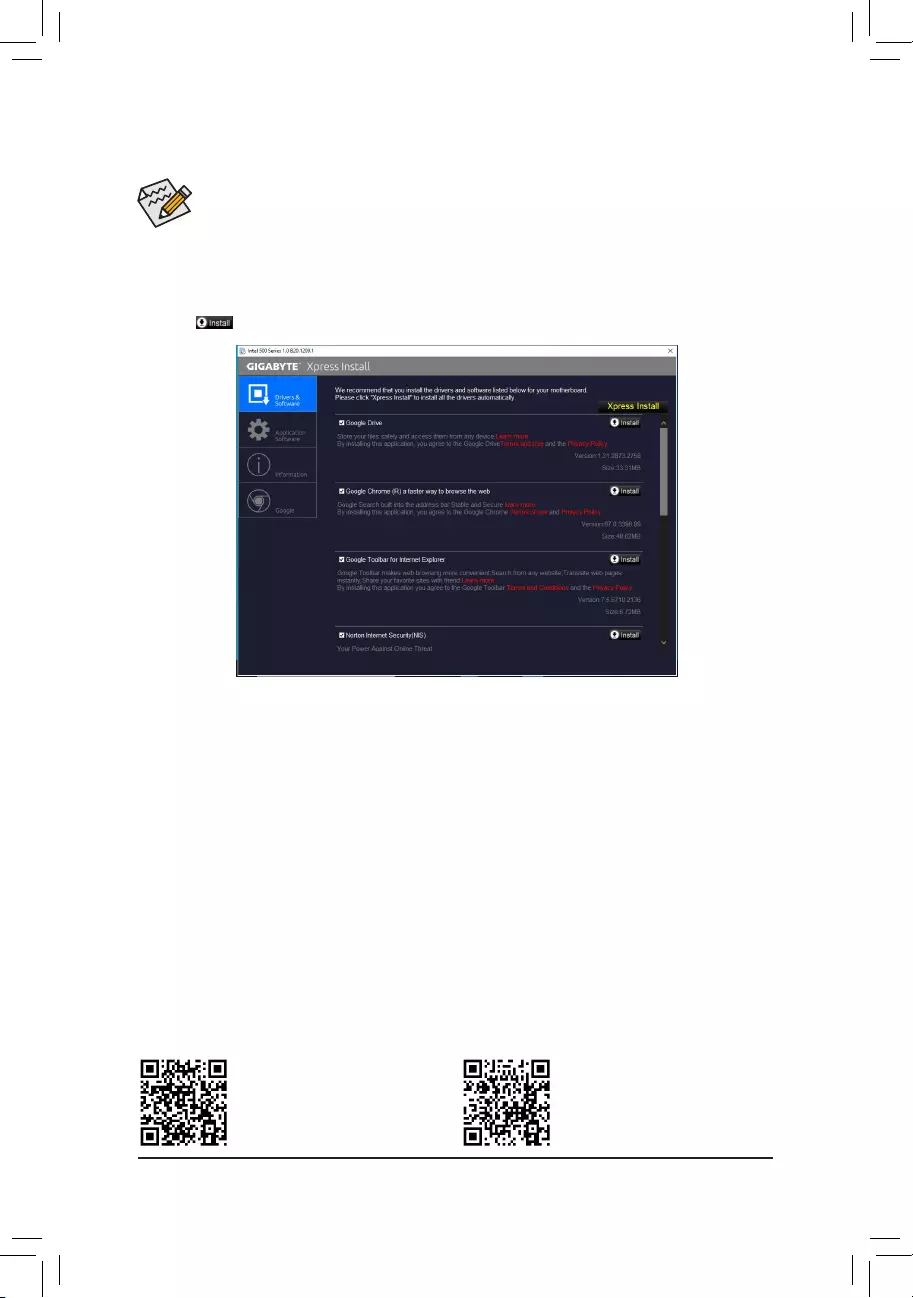
•Before installing the drivers, rst install the operating system.
•After installing the operating system, insert the motherboard driver disc into your optical drive. Click
on the message «Tap to choose what happens with this disc» on the top-right corner of the screen
and select «Run Run.exe.» (Or go to My Computer, double-click the optical drive and execute the
Run.exe program.)
«Xpress Install» will automatically scan your system and then list all of the drivers that are recommended to
install. You can click the Xpress Install button and «Xpress Install» will install all of the selected drivers. Or click
the arrow icon to individually install the drivers you need.
3-3 Drivers Installation
Please visit GIGABYTE’s website for
more software information.
Please visit GIGABYTE’s website for
more troubleshooting information.
— 46 —

Supplier’s Declaration of Conformity
47 CFR § 2.1077 Compliance Information
Product Name: Motherboard
Trade Name: GIGABYTE
Model Number: Z590 UD AC / Z590 UD
Responsible Party – U.S. Contact Information: G.B.T. Inc.
Address: 17358 Railroad street, City Of Industry, CA91748
Tel.: 1-626-854-9338
Internet contact information: https://www.gigabyte.com
FCC Compliance Statement:
This device complies with Part 15 of the FCC Rules, Subpart B, Unintentional Radiators.
Operation is subject to the following two conditions: (1) This device may not cause harmful interference, and (2) this
device must accept any interference received, including interference that may cause undesired operation.
Antenna use:
In order to comply with FCC RF exposure limits, low gain integrated
antennas should be located at a minimum distance of 7.9 inches (20 cm)
or more from the body of all persons.
Explosive Device Proximity Warning
Warning: Do not operate a portable transmitter (such as a wireless network
device) near unshielded blasting caps or in an explosive environment
unless the device has been modied to be qualied for such use.
Antenna Warning
The wireless adapter is not designed for use with high-gain antennas.
Use On Aircraft Caution
Caution: Regulations of the FCC and FAA prohibit airborne operation of
radio-frequency wireless devices because their signals could interfere with
critical aircraft instruments.
Other Wireless Devices
Safety Notices for Other Devices in the Wireless Network: Refer to the
documentation supplied with wireless Ethernet adapters or other devices
in the wireless network.
Canada, Canada-Industry Notice:
This device complies with Industry Canada license-exempt RSS
standard(s). Operation is subject to the following two conditions:
(1) this device may not cause interference, and
(2) this device must accept any interference, including interference that
may cause undesired operation of the device.
Cet appareil est conforme aux normes Canada d’Industrie de RSS
permis-exempt. L’utilisation est assujetti aux deux conditions suivantes:
(1) le dispositif ne doit pas produire de brouillage préjudiciable, et
(2) ce dispositif doit accepter tout brouillage reçu, y compris un brouillage
susceptible de provoquer un fonctionnement indésirable.
Caution: When using IEEE 802.11a wireless LAN, this product is restricted
to indoor use due to its operation in the 5.15-to 5.25-GHz frequency
range. Industry Canada requires this product to be used indoors for the
frequency range of 5.15 GHz to 5.25 GHz to reduce the potential for
harmful interference to co-channel mobile satellite systems. High power
radar is allocated as the primary user of the 5.25-to 5.35-GHz and 5.65 to
5.85-GHz bands. These radar stations can cause interference with and/or
damage to this device. The maximum allowed antenna gain for use with
this device is 6dBi in order tocomply with the E.I.R.P limit for the 5.25-to
5.35 and 5.725 to 5.85 GHz frequency range in point-to-point operation. To
comply with RF exposure requirements all antennas should be located at a
minimum distance of 20cm, or the minimum separation distance allowed
by the module approval, from the body of all persons.
Attention: l’utilisation d’un réseau sans l IEEE802.11a est restreinte à
une utilisation en intérieur à cause du fonctionnement dansla bande de
fréquence 5.15-5.25 GHz. Industry Canada requiert que ce produit soit
utilisé à l’intérieur des bâtiments pour la bande de fréquence 5.15-5.25
GHz an de réduire les possibilités d’interférences nuisibles aux canaux
co-existants des systèmes de transmission satellites. Les radars de
puissances ont fait l’objet d’une allocation primaire de fréquences dans
les bandes 5.25-5.35 GHz et 5.65-5.85 GHz. Ces stations radar peuvent
créer des interférences avec ce produit et/ou lui être nuisible. Le gain
d’antenne maximum permissible pour une utilisation avec ce produit est de
6 dBi an d’être conforme aux limites de puissance isotropique rayonnée
équivalente (P.I.R.E.) applicable.
dans les bandes 5.25-5.35 GHz et 5.725-5.85 GHz en fonctionnement
point-à-point. Pour se conformer aux conditions d’exposition de RF toutes
les antennes devraient être localisées à une distance minimum de 20
cm, ou la distance de séparation minimum permise par l’approbation du
module, du corps de toutes les personnes.
Regulatory Notices
United States of America, Federal Communications Commission Statement
The FCC with its action in ET Docket 96-8 has adopted a safety standard for human exposure to radio frequency (RF) electromagnetic energy emitted
by FCC certied equipment. The Intel PRO/Wireless 5000 LAN products meet the Human Exposure limits found in OET Bulletin 65, 2001, and ANSI/
IEEE C95.1, 1992. Proper operation of this radio according to the instructions found in this manual will result in exposure substantially below the FCC’s
recommended limits.
The following safety precautions should be observed:
•Do not touch or move antenna while the unit is transmitting or receiving.
•Do not hold any component containing the radio such that the antenna is very close or touching any exposed parts of the body, especially the face
or eyes, while transmitting.
•Do not operate the radio or attempt to transmit data unless the antenna is connected; if not, the radio may be damaged.
•Use in specic environments:
— The use of wireless devices in hazardous locations is limited by the constraints posed by the safety directors of such environments.
— The use of wireless devices on airplanes is governed by the Federal Aviation Administration (FAA).
— The use of wireless devices in hospitals is restricted to the limits set forth by each hospital.
— 47 —

European Union (EU) CE Declaration of Conformity
This device complies with the following directives: Electromagnetic
Compatibility Directive 2014/30/EU, Low-voltage Directive 2014/35/EU,
Radio Equipment Directive 2014/53/EU, ErP Directive 2009/125/EC, RoHS
directive (recast) 2011/65/EU & the 2015/863 Statement.
This product has been tested and found to comply with all essential
requirements of the Directives.
European Union (EU) RoHS (recast) Directive 2011/65/EU & the
European Commission Delegated Directive (EU) 2015/863 Statement
GIGABYTE products have not intended to add and safe from hazardous
substances (Cd, Pb, Hg, Cr+6, PBDE, PBB, DEHP, BBP, DBP and DIBP).
The parts and components have been carefully selected to meet RoHS
requirement. Moreover, we at GIGABYTE are continuing our efforts to
develop products that do not use internationally banned toxic chemicals.
European Union (EU) Community Waste Electrical & Electronic
Equipment (WEEE) Directive Statement
GIGABYTE will fulll the national laws as interpreted from the 2012/19/
EU WEEE (Waste Electrical and Electronic Equipment) (recast) directive.
The WEEE Directive species the treatment, collection, recycling and
disposal of electric and electronic devices and their components. Under
the Directive, used equipment must be marked, collected separately, and
disposed of properly.
WEEE Symbol Statement
The symbol shown below is on the product or on its
packaging, which indicates that this product must not be
disposed of with other waste. Instead, the device should be
taken to the waste collection centers for activation of the
treatment, collection, recycling and disposal procedure.
For more information about where you can drop off your waste equipment
for recycling, please contact your local government ofce, your household
waste disposal service or where you purchased the product for details of
environmentally safe recycling.
End of Life Directives-Recycling
The symbol shown below is on the product or on its packaging,
which indicates that this product must not be disposed of with
other waste. Instead, the device should be taken to the waste
collection centers for activation of the treatment, collection,
recycling and disposal procedure.
Déclaration de Conformité aux Directives de l’Union européenne (UE)
Cet appareil portant la marque CE est conforme aux directives de l’UE
suivantes: directive Compatibilité Electromagnétique 2014/30/UE, directive
Basse Tension 2014/35/UE, directive équipements radioélectriques
2014/53/UE, la directive RoHS II 2011/65/UE & la déclaration 2015/863.
La conformité à ces directives est évaluée sur la base des normes
européennes harmonisées applicables.
European Union (EU) CE-Konformitätserklärung
Dieses Produkte mit CE-Kennzeichnung erfüllen folgenden EU-Richtlinien:
EMV-Richtlinie 2014/30/EU, Niederspannungsrichtlinie 2014/35/EU,
Funkanlagen Richtlinie 2014/53/EU, RoHS-Richtlinie 2011/65/EU erfüllt
und die 2015/863 Erklärung.
Die Konformität mit diesen Richtlinien wird unter Verwendung der
entsprechenden Standards zurEuropäischen Normierung beurteilt.
CE declaração de conformidade
Este produto com a marcação CE estão em conformidade com das
seguintes Diretivas UE: Diretiva Baixa Tensão 2014/35/EU; Diretiva
CEM 2014/30/EU; Diretiva RSP 2011/65/UE e a declaração 2015/863.
A conformidade com estas diretivas é vericada utilizando as normas
europeias harmonizadas.
CE Declaración de conformidad
Este producto que llevan la marca CE cumplen con las siguientes
Directivas de la Unión Europea: Directiva EMC 2014/30/EU, Directiva de
bajo voltaje 2014/35/EU, Directiva de equipamentos de rádio 2014/53/EU,
Directiva RoHS 2011/65/EU y la Declaración 2015/863.
El cumplimiento de estas directivas se evalúa mediante las normas
europeas armonizadas.
CE Dichiarazione di conformità
I prodotti con il marchio CE sono conformi con una o più delle seguenti
Direttive UE, come applicabile: Direttiva EMC 2014/30/UE, Direttiva sulla
bassa tensione 2014/35/UE, Direttiva di apparecchiature radio 2014/53/
UE, Direttiva RoHS 2011/65/EU e Dichiarazione 2015/863.
La conformità con tali direttive viene valutata utilizzando gli Standard
europei armonizzati applicabili.
DeklaracjazgodnościUEUniiEuropejskiej
Urządzenie jest zgodne z następującymi dyrektywami: Dyrektywa
kompatybilności elektromagnetycznej 2014/30/UE, Dyrektywa
niskonapięciowej 2014/35/UE, Dyrektywa urządzeń radiowych 2014/53/
UE, Dyrektywa RoHS 2011/65/UE i dyrektywa2015/863.
Niniejsze urządzenie zostało poddane testom i stwierdzono jego zgodność
z wymaganiami dyrektywy.
ESProhlášeníoshodě
Toto zařízení splňuje požadavky Směrnice o Elektromagnetické
kompatibilitě 2014/30/EU, Směrnice o Nízkém napětí 2014/35/EU,
Směrnice o rádiových zařízeních 2014/53/EU, Směrnice RoHS 2011/65/
EU a 2015/863.
Tento produkt byl testován a bylo shledáno, že splňuje všechny základní
požadavky směrnic.
EKmegfelelőséginyilatkozata
A termék megfelelnek az alábbi irányelvek és szabványok
követelményeinek, azok a kiállításidőpontjában érvényes, aktuális
változatában: EMC irányelv 2014/30/EU, Kisfeszültségű villamos
berendezésekre vonatkozó irányelv 2014/35/EU, rádióberendezések
irányelv 2014/53/EU, RoHS irányelv 2011/65/EU és 2015/863.
ΔήλωσησυμμόρφωσηςΕΕ
Είναι σε συμμόρφωση με τις διατάξεις των παρακάτω Οδηγιών
της Ευρωπαϊκής Κοινότητας: Οδηγία 2014/30/ΕΕ σχετικά με την
ηλεκτρομαγνητική συμβατότητα, Οοδηγία χαμηλή τάση 2014/35/EU,
Οδηγία 2014/53/ΕΕ σε ραδιοεξοπλισμό, Οδηγία RoHS 2011/65/ΕΕ
και 2015/863.
Η συμμόρφωση με αυτές τις οδηγίες αξιολογείται χρησιμοποιώντας τα
ισχύοντα εναρμονισμένα ευρωπαϊκά πρότυπα.
Under Industry Canada regulations, this radio transmitter may only operate
using an antenna of a type and maximum (or lesser) gain approved for
the transmitter by Industry Canada. To reduce potential radio interference
to other users, the antenna type and its gain should be chosen so that
the equivalent isotropically radiated power (e.i.r.p.) is not more than that
necessary for successful communication.
Conformément à la réglementation d’Industrie Canada, le présent émetteur
radio peut fonctionner avec une antenne d’un type et d’un gain maximal
(ou inférieur) approuvé pour l’émetteur par Industrie Canada. Dans le
but de réduire les risques de brouillage radio électrique à l’intention des
autres utilisateurs, il faut choisir le type d’antenne et son gain de sorte
que la puissance isotrope rayonnée équivalente (p.i.r.e.) ne dépasse pas
l’intensité nécessaire à l’établissement d’une communication satisfaisante.
— 48 —
European Community Radio Equipment Directive Compliance Statement:
This equipment complies with all the requirements and other relevant provisions of Radio Equipment Directive 2014/53/EU.
This equipment is suitable for home and ofce use in all the European Community Member States and EFTA Member States.
The low band 5.15 -5.35 GHz is for indoor use only.
AT BE BG CH CY CZ DE
DK EE EL ES FI FR HR
HU IE IS IT LI LT LU
LV MT NL PL PT RO SE
SI SK TR UK
Taiwan NCC Wireless Statements / 無線設備警告聲明:
低功率電波輻射性電機管理辦法
第十二條: 經型式認證合格之低功率射頻電機,非經許可,公司、商號或使用者均不得擅自變更頻率、加大功率或變更原
設計之特性及功能。
第十四條: 低功率射頻電機之使用不得影響飛航安全及干擾合法通信;經發現有干擾現象時,應立即停用,並改善至無干
擾時方得繼續使用。前項合法通信,指依電信法規定作業之無線電通信。低功率射頻電機須忍受合法通信或工
業、科學及醫療用電波輻射性電機設備之干擾。
在5.25-5.35 秭赫頻帶內操作之無線資訊傳輸設備,限於室內使用。
Korea KCC NCC Wireless Statement:
5,25GHz — 5,35 GHz 대역을 사용하는 무선 장치는 실내에서만 사용하도록 제한됩니다。
Japan Wireless Statement:
5.15 GHz 帯 ~ 5.35 GHz 帯: 屋内のみの使用。
Wireless module country approvals:
To identify your Motherboard version or revision number, look for “REV: X.X” printed on the PCB on the top left corner of the Motherboard. For
example, «REV:1.0» means the revision of the motherboard is 1.0. .
Motherboard revision no.: Wireless module manufacturer, model name:
Z590 UD AC rev. 1.0 Intel® Corporation 9462NGW
Z590 UD AC rev. 1.1 Intel® Corporation 9560NGW
Country approvals for wireless module 9462NGW:
Country approvals for wireless module 9560NGW:
— 49 —

— 50 —

— 51 —
Contact Us
GIGA-BYTE TECHNOLOGY CO., LTD.
Address: No.6, Baoqiang Rd., Xindian Dist., New Taipei City 231, Taiwan
TEL: +886-2-8912-4000, FAX: +886-2-8912-4005
Tech. and Non-Tech. Support (Sales/Marketing) : https://esupport.gigabyte.com
WEB address (English): https://www.gigabyte.com
WEB address (Chinese): https://www.gigabyte.com/tw
•GIGABYTE eSupport
To submit a technical or non-technical (Sales/Marketing) question, please link to:
https://esupport.gigabyte.com
— 52 —
Все способы:
- Видео инструкция
- Настраиваем БИОС Гигабайт
- Настройки RAM
- Параметры GPU
- Настройка вращения кулеров
- Оповещения о перегреве
- Настройки загрузки
- Сохранение настроек
- Вопросы и ответы: 99
Многие пользователи, которые самостоятельно собирают себе компьютер, часто выбирают в качестве материнской платы продукцию компании Gigabyte. После сборки компьютера необходимо соответствующим образом настроить BIOS, и сегодня мы хотим познакомить вас с этой процедурой для рассматриваемых «материнок».
Видео инструкция
Настраиваем БИОС Гигабайт
Первое, с чего стоит начать процесс настройки – вход в режим низкоуровневого управления платой. На современных «материнках» указанного производителя за вход в БИОС отвечает клавиша Del. Её следует нажимать в момент после включения компьютера и появления заставки.
Читайте также: Как войти в BIOS на компьютере
После загрузки в BIOS вы можете наблюдать следующую картину.
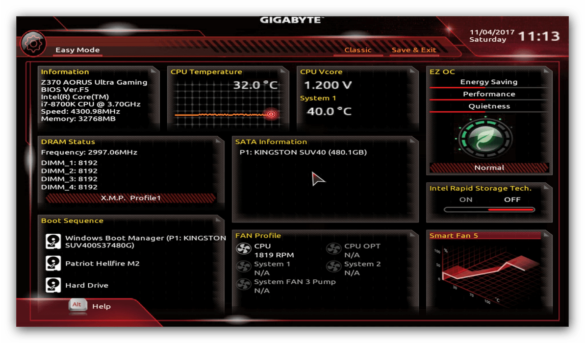
Как видите, производитель использует UEFI, как более безопасный и удобный для пользователя вариант. Вся инструкция далее будет ориентирована именно на UEFI-вариант.
Настройки RAM
Первое, что нужно сконфигурировать в параметрах БИОСа – тайминги оперативной памяти. Из-за неправильно установленных настроек компьютер может работать некорректно поэтому внимательно следуйте инструкции далее:
- Из главного меню перейдите к параметру «Advanced Memory Settings», расположенному на вкладке «M.I.T».

В нём перейдите к опции «Extreme Memory Profile (X.M.P.)».
Тип профиля следует выбирать исходя из типа установленной RAM. Например, для DDR4 подойдёт вариант «Profile1», для DDR3 – «Profile2».
- Также доступны опции для любителей разгона – можно вручную изменить тайминги и вольтаж для более быстрой работы модулей памяти.
Подробнее: Разгон оперативной памяти
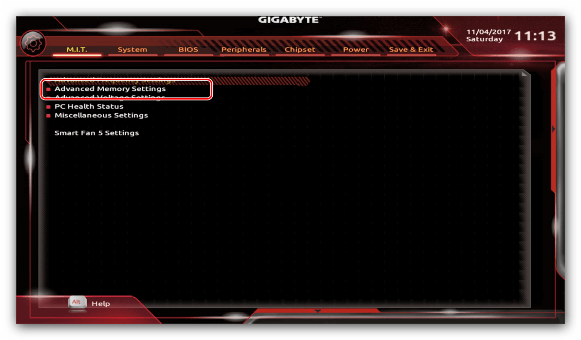
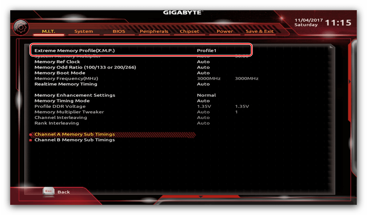
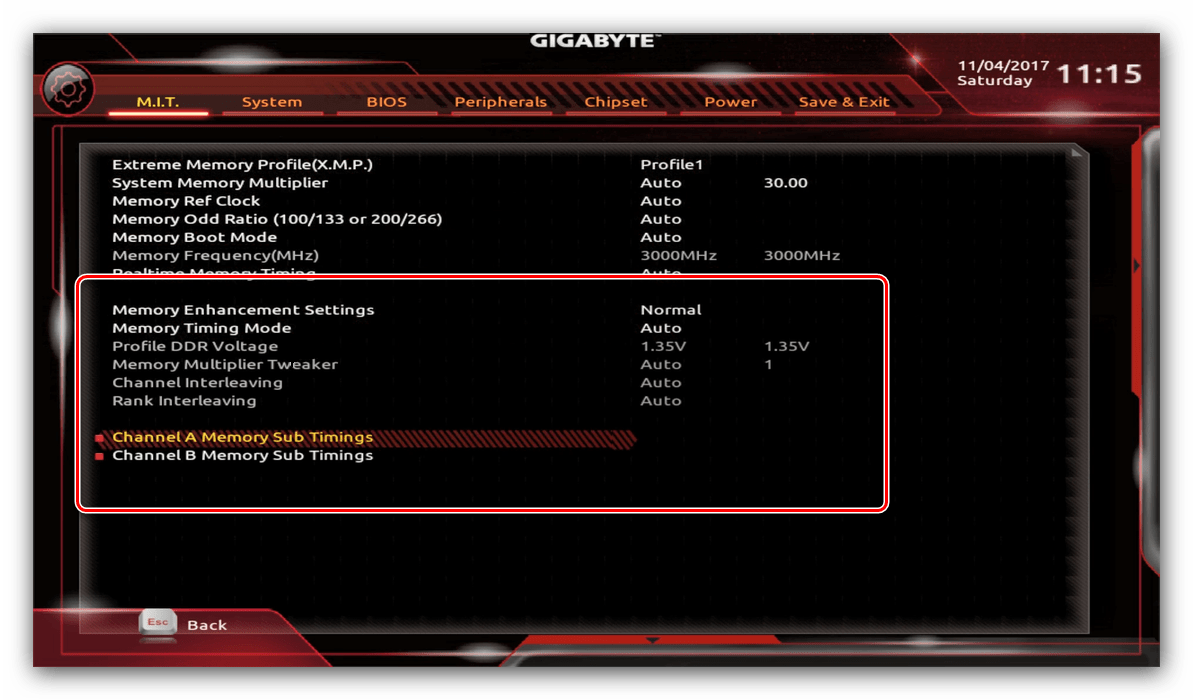
Параметры GPU
Через UEFI BIOS плат Gigabyte можно настроить работу компьютера с видеоадаптерами. Для этого перейдите на вкладку «Peripherals».
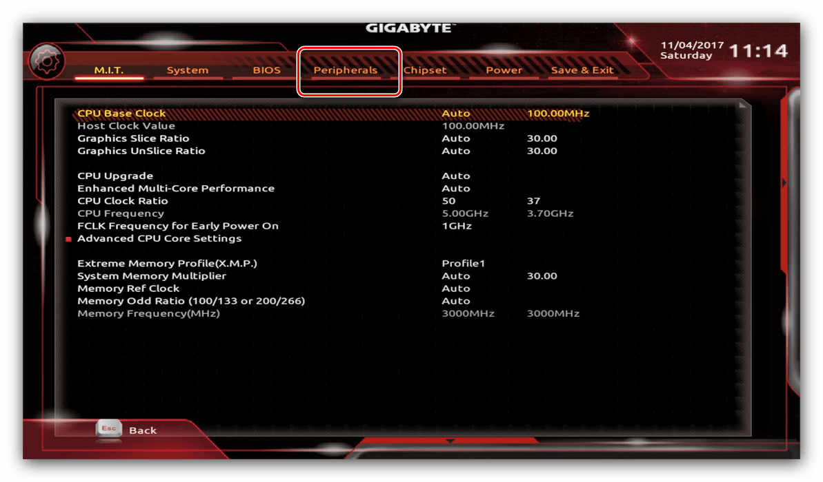
- Самой важной опцией здесь является «Initial Display Output», позволяющая установить основной используемый графический процессор. Если на компьютере на момент настройки нет выделенного GPU, следует выбрать вариант «IGFX». Для выбора дискретной видеокарты установите «PCIe 1 Slot» или «PCIe 2 Slot», зависит от порта, к которому подключен внешний графический адаптер.
- В разделе «Chipset» можно либо полностью отключить встроенную графику для снижения нагрузки на CPU (опция «Internal Graphics» в положении «Disabled»), либо увеличить или уменьшить объём оперативной памяти, которая потребляется этим компонентом (опции «DVMT Pre-Allocated» и «DVMT Total Gfx Mem»). Обратите внимание, доступность этой возможности зависит как от процессора, так и от модели платы.
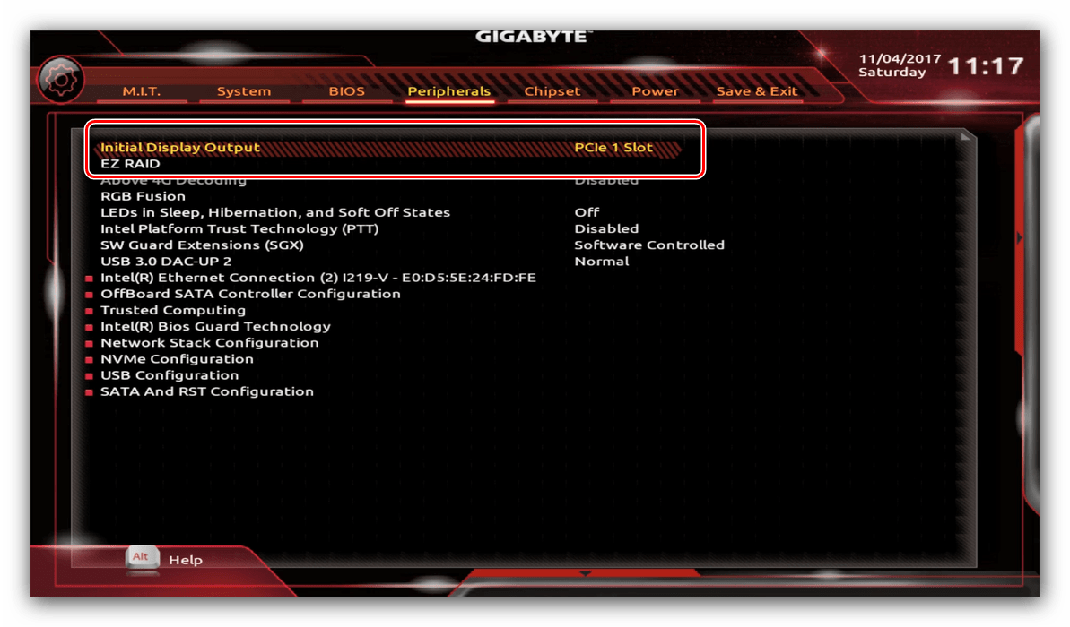
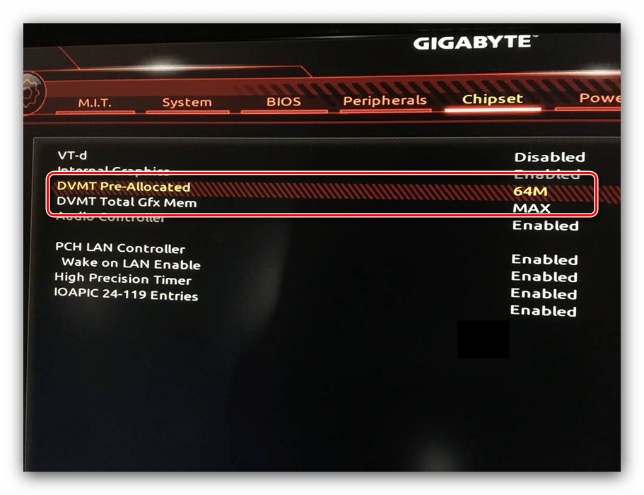
Настройка вращения кулеров
- Нелишним также будет сконфигурировать скорость вращения системных вентиляторов. Для этого перейдите воспользуйтесь опцией «Smart Fan 5».
- В зависимости от количества установленных на плате кулеров в меню «Monitor» будет доступно управление ими.
Скорости вращения каждого из них стоит установить в положение «Normal» – это обеспечит автоматический режим работы в зависимости от нагрузки.
Можно также настроить режим работы кулера вручную (вариант «Manual») или выбрать минимально шумный, но обеспечивающий наихудшее охлаждение (параметр «Silent»).
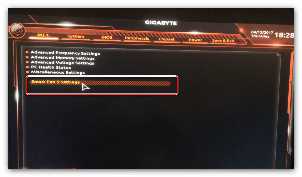
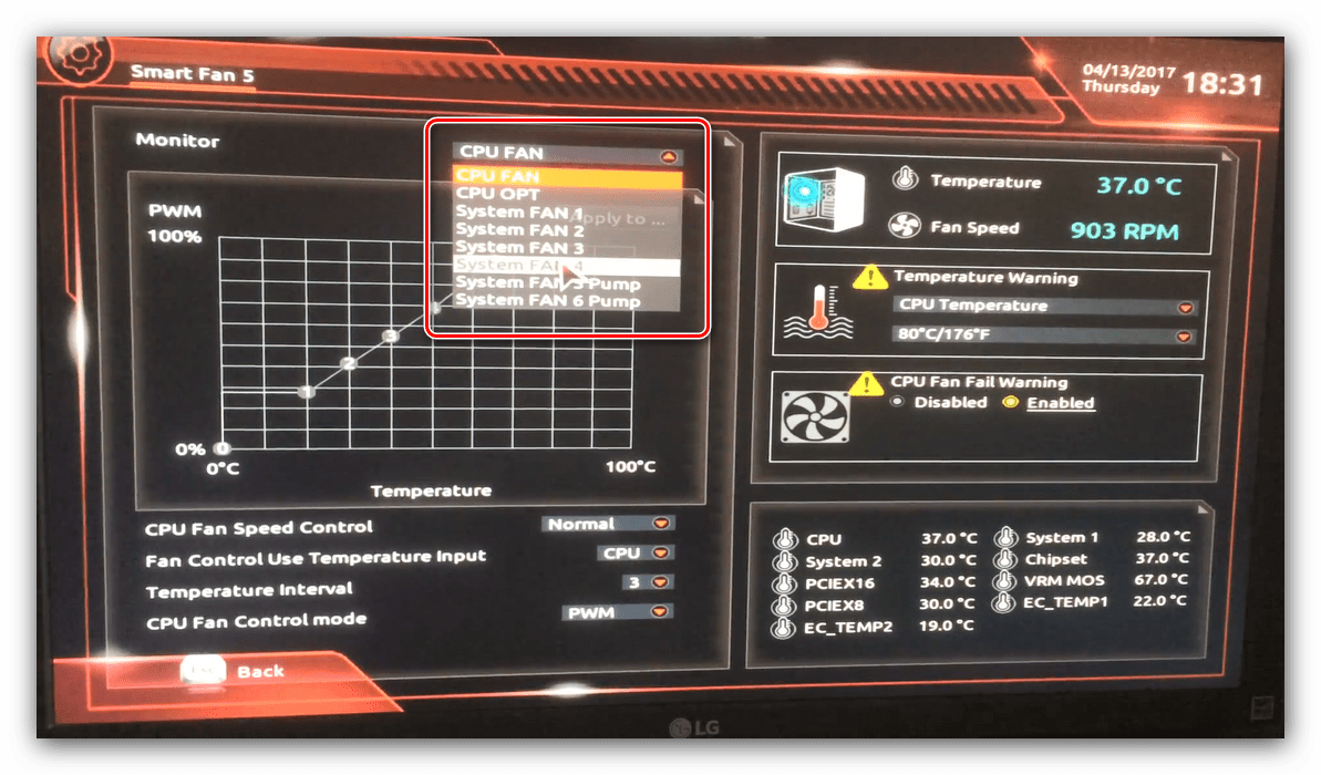
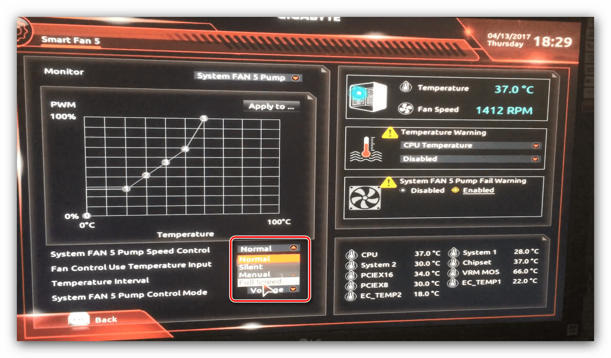
Оповещения о перегреве
Также в платы рассматриваемого производителя встроено средство защиты компонентов компьютера от перегрева: при достижении порогового значения температуры пользователь получит оповещение о необходимости выключения машины. Настроить отображение этих уведомлений можно в разделе «Smart Fan 5», упомянутом на предыдущем этапе.
- Нужные нам опции расположены в блоке «Temperature Warning». Здесь потребуется вручную определить максимально допустимое значение температуры процессора. Для CPU с низким тепловыделением достаточно выбрать значение в 70 °C, а если TDP у процессора высокий, то 90 °C.
- По желанию можно также настроить оповещение о неполадках с кулером процессора – для этого в блоке «System FAN 5 Pump Fail Warning» отметьте вариант «Enabled».
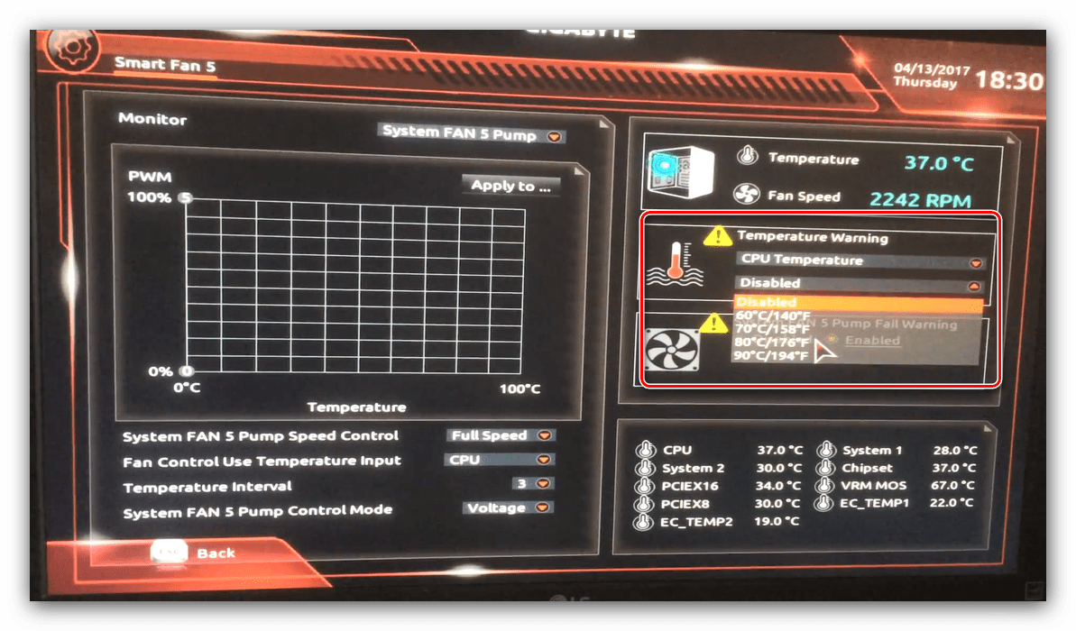
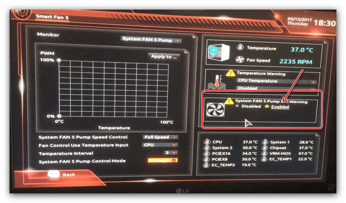
Настройки загрузки
Последние важные параметры, которые следует настроить – приоритет загрузки и включение режима AHCI.
- Зайдите в раздел «BIOS Features» и воспользуйтесь опцией «Boot Option Priorities».
Здесь выберите нужный загрузочный носитель. Доступны как обычные жесткие диски, так и твердотельные накопители. Также можно выбрать флешку или оптический диск.
- Режим AHCI, необходимый для современных HDD и SSD, включается на вкладке «Peripherals», в разделах «SATA and RST Configuration» – «SATA Mode Selection».
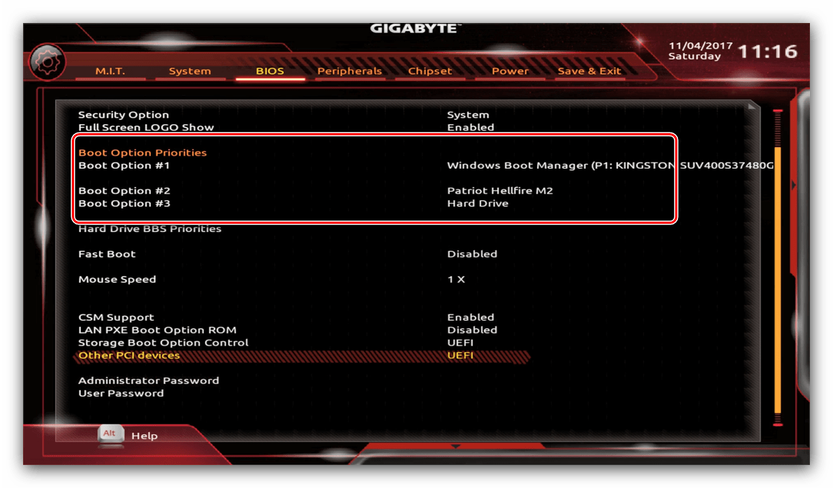
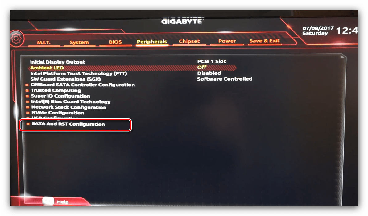
Сохранение настроек
- Для сохранения введённых параметров воспользуйтесь закладкой «Save & Exit».
- Сохранение параметров происходит после нажатия на пункт «Save & Exit Setup».
Также можно выйти без сохранения (если не уверены, что ввели всё правильно), используйте опцию «Exit Without Saving», или сбросить настройки БИОС к заводским, за что отвечает вариант «Load Optimized Defaults».
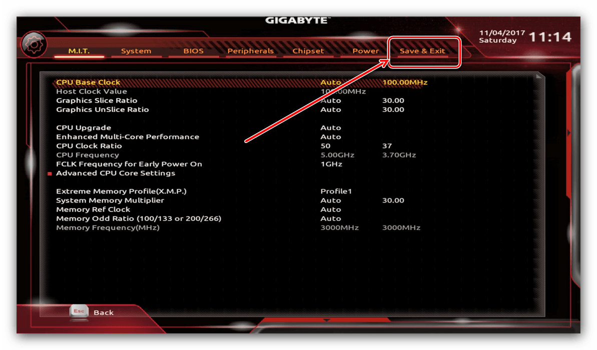
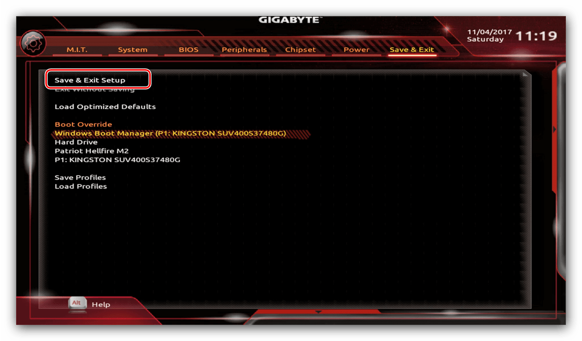
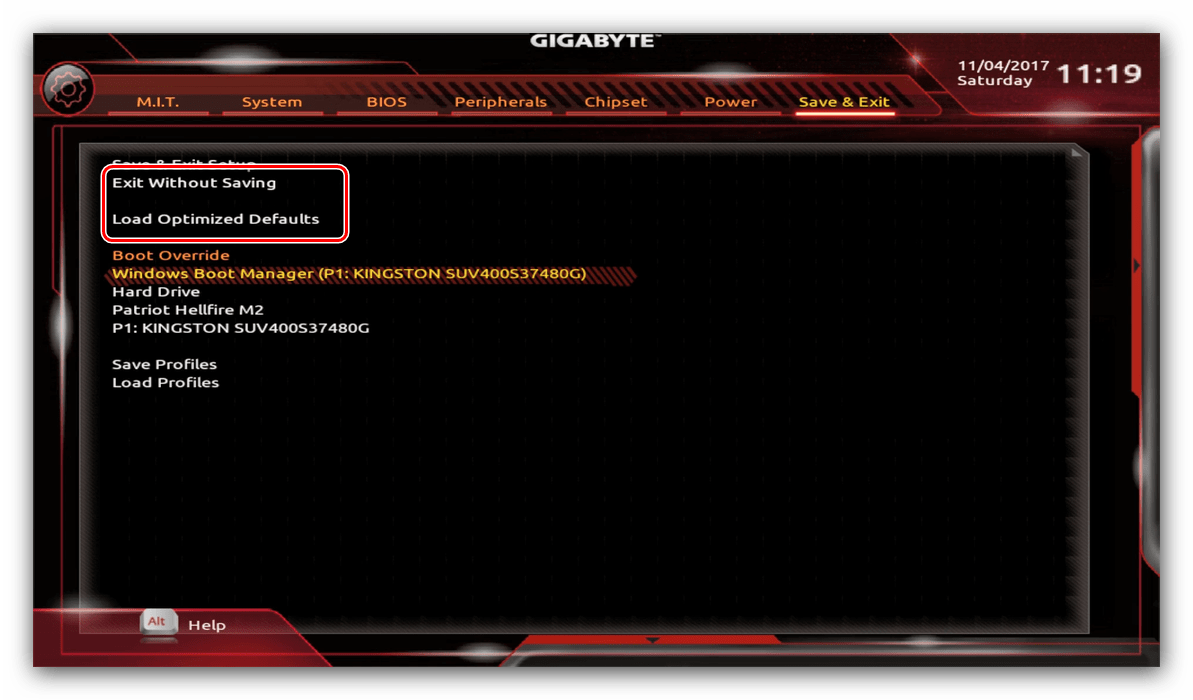
Таким образом мы закончили настройку основных параметров BIOS на материнской плате Gigabyte.
GIGABYTE
Loading…
Z
- Z370M AORUS Gaming
- Z370M D3H
- Z370M DS3H
- Z370P D3
- Z3902
- Z390 Aorus elite
- Z390 Aorus Pro
- Z390 Aorus Ultra
- Z390 Aorus Xtreme
- Z390 AORUS XTREME WATERFORCE2
- Z390 AORUS XTREME WATERFORCE 5G
- Z390 D
- Z390 Designare
- Z390 Gaming SLI
- Z390 Gaming X
- Z390 I Aorus Pro WIFI
- Z390 M
- Z390 M Gaming
- Z390 UD
- Z490
- Z490 Aorus elite
- Z490 Aorus Master
- Z490 AORUS MASTER WATERFORCE
- Z490 AORUS MASTER WF
- Z490 Aorus Pro AX2
- Z490 Aorus Ultra
- Z490 Aorus Xtreme
- Z490 Aorus Xtreme Waterforce
- Z490 AORUS XTREME WF
- Z490 Gaming X
- Z490 Gaming X AX
- Z490I Aorus Ultra
- Z490M
- Z490M Gaming X
- Z490 UD
- Z490 Vision D
- Z490 VISION G
- Z590
- Z590 AORUS ELITE2
- Z590 AORUS ELITE AX2
- Z590 AORUS MASTER
- Z590 AORUS TACHYON
- Z590 AORUS ULTRA
- Z590 AORUS XTREME
- Z590 AORUS XTREME WATERFORCE
- Z590 AORUS XTREME WB2
- Z590 D2
- Z590 GAMING X2
- Z590 GAMING X AX2
- Z590I AORUS ULTRA
- Z590I VISION D3
- Z590M2
- Z590M GAMING X4
- Z590 UD
- Z590 UD AC
- Z590 VISION D2
- Z590 VISION G2
Loading…
Loading…
Nothing found
Z590 UD AC
Users guide
52 pgs14.59 Mb0
Table of contents
Loading…
…
GIGABYTE Users guide
Download
Specifications and Main Features
Frequently Asked Questions
User Manual

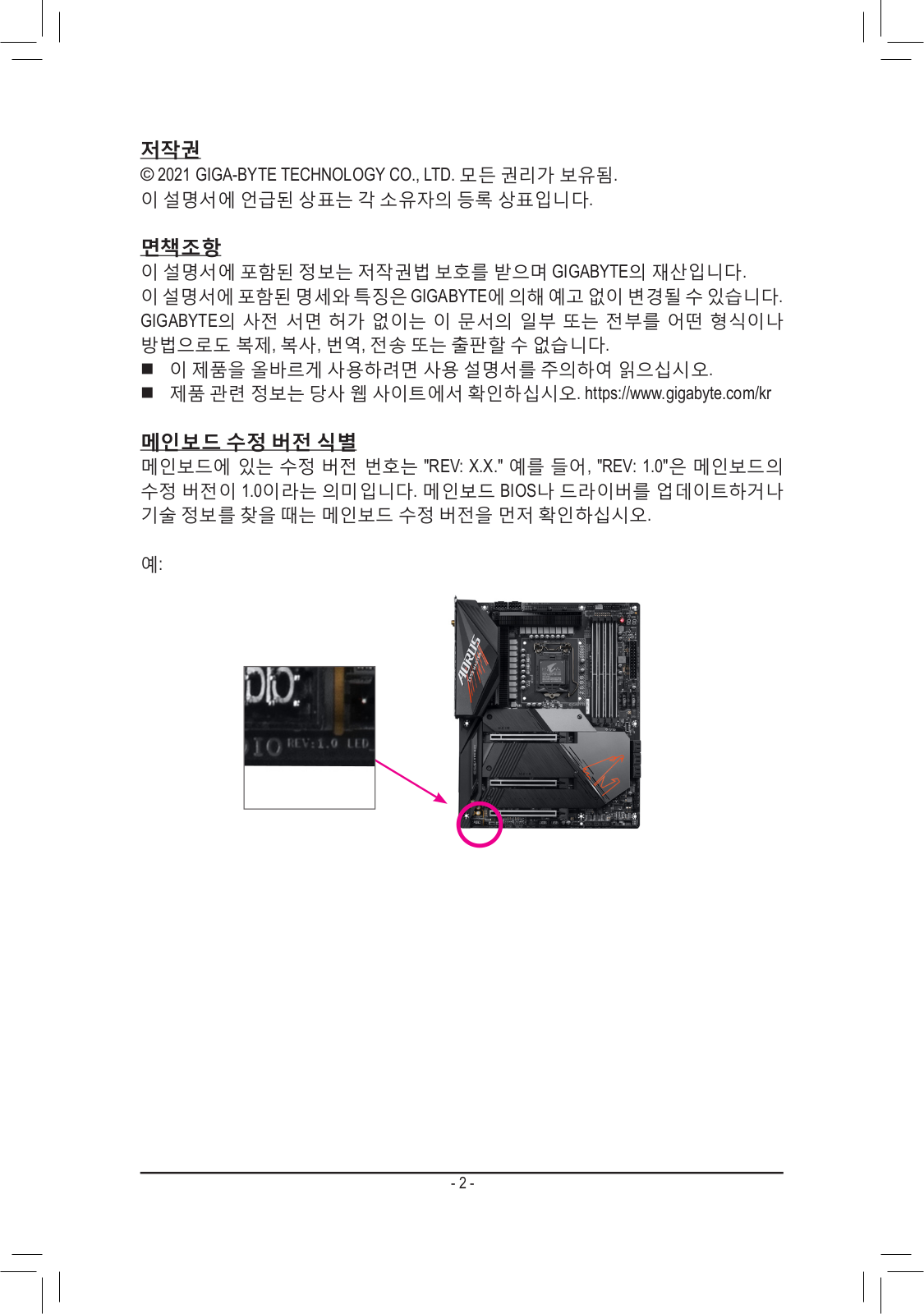


Loading…
+ 36 hidden pages
You need points to download manuals.
1 point = 1 manual.
You can buy points or you can get point for every manual you upload.
Buy points
Upload your manuals
Gigabyte Z590 UD AC – это популярная материнская плата, которая предлагает широкие возможности настройки BIOS для оптимизации работы системы. В этой статье мы рассмотрим основные шаги, которые помогут вам правильно настроить BIOS на материнской плате Gigabyte Z590 UD AC, а также предоставим некоторые полезные советы, которые помогут вам получить максимальную производительность.
Первым шагом является запуск компьютера и вход в BIOS. Для этого нажмите определенный клавишный комбинация во время загрузки компьютера. Обычно это клавиша Del или F2. Когда вы находитесь в BIOS, вы увидите различные категории, такие как «Main», «Advanced», «Boot» и т. д., которые позволяют вам настраивать различные параметры системы.
Важно помнить, что внесение неправильных изменений в BIOS может привести к непредсказуемым результатам и даже повредить вашу систему. Поэтому перед внесением изменений, делайте соответствующие пояснения и будьте осторожны в процессе настройки.
Начните с перехода в раздел «Main» BIOS, где вы можете настроить основные параметры системы, такие как дата и время, язык интерфейса и устройства загрузки. Убедитесь, что эти параметры настроены правильно, чтобы предотвратить возможные проблемы.
Затем перейдите в раздел «Advanced», где вы найдете больше опций для настройки процессора, памяти, видеокарты и других компонентов. Например, вы можете настроить тактовую частоту процессора, напряжение питания, активировать функции разгона и многое другое. Будьте осторожны при изменении этих параметров, так как ошибочные настройки могут привести к сбоям системы или перегреву компонентов.
Содержание
- Как настроить биос Gigabyte Z590 UD AC
- Важность биоса Gigabyte Z590 UD AC
- Процесс обновления биоса Gigabyte Z590 UD AC
- Основные параметры настройки биоса Gigabyte Z590 UD AC
- Советы по оптимизации работы BIOS Gigabyte Z590 UD AC:
- Настройка разгона и питания в биосе Gigabyte Z590 UD AC
- Использование профилей в биосе Gigabyte Z590 UD AC
- Управление вентиляторами в биосе Gigabyte Z590 UD AC
Как настроить биос Gigabyte Z590 UD AC
- Перезагрузите компьютер и нажмите клавишу «Delete», чтобы войти в биос.
- В главном меню биоса выберите вкладку «Advanced» (Расширенные настройки).
- Настройте параметры процессора. Здесь вы можете изменить такие параметры, как частота процессора, напряжение и т.д.
- Настройте параметры оперативной памяти. Установите нужную частоту, тайминги и напряжение для RAM.
- Настройте параметры хранения данных. Здесь вы можете выбрать порядок загрузки устройств и настроить параметры SATA, NVMe и других устройств хранения данных.
- Настройте параметры графической карты. Если у вас установлена дискретная графическая карта, вы можете настроить различные параметры, связанные с графикой.
- Настройте параметры питания. Здесь вы можете установить различные режимы энергосбережения и настроить параметры питания компьютера.
- Сохраните изменения, нажав клавишу «F10» и выбрав опцию «Save and Exit» (Сохранить и выйти).
После этого компьютер будет перезагружен с новыми настройками биоса. Обратите внимание, что неверные настройки биоса могут привести к неправильной работе компьютера или даже его неработоспособности. Поэтому будьте внимательны и ознакомьтесь с руководством пользователя материнской платы Gigabyte Z590 UD AC перед настройкой биоса.
Важность биоса Gigabyte Z590 UD AC
Биос играет критическую роль в обеспечении стабильной и надежной работы системы. Он отвечает за инициализацию оборудования при запуске компьютера, настройку параметров работы, а также управление энергопотреблением.
Производитель материнской платы регулярно выпускает обновления для биоса, которые могут исправлять ошибки, повышать совместимость с новыми компонентами и улучшать производительность. Поэтому рекомендуется регулярно проверять наличие и устанавливать обновления для биоса Gigabyte Z590 UD AC.
Для настройки биоса Gigabyte Z590 UD AC необходимо ознакомиться с инструкцией, предоставленной производителем материнской платы. В инструкции указаны все доступные опции и настройки, которые можно изменить в биосе. Рекомендуется быть внимательным и осторожным при изменении параметров, чтобы не нарушить работу системы или получить нежелательные результаты.
Также следует учитывать, что биос может быть защищен паролем. Если установлен пароль, то для доступа к настройкам биоса потребуется его ввод. Пароль может быть установлен пользователем или предустановлен производителем.
| Преимущества настройки биоса Gigabyte Z590 UD AC: | Ключевые моменты при настройке биоса Gigabyte Z590 UD AC: |
|---|---|
| 1. Улучшение производительности компьютера. | 1. Внимательно ознакомиться с инструкцией по настройке биоса. |
| 2. Увеличение стабильности работы системы. | 2. Проверить наличие и установить обновления для биоса. |
| 3. Улучшение совместимости с новым оборудованием. | 3. Быть осторожным и внимательным при изменении параметров. |
| 4. Оптимизация энергопотребления. | 4. Учесть возможность наличия пароля для доступа к биосу. |
В целом, настройка биоса Gigabyte Z590 UD AC является важным шагом при работе с данной материнской платой. Грамотная настройка позволит получить оптимальную производительность и стабильную работу системы.
Процесс обновления биоса Gigabyte Z590 UD AC
Вот несколько этапов, которые нужно выполнить для обновления биоса:
1. Загрузка последней версии биоса:
Первым шагом является проверка официального сайта Gigabyte на наличие самой последней версии биоса для материнской платы Z590 UD AC. Скачайте файл с прошивкой на компьютер, убедитесь, что файл соответствует вашей модели материнской платы и имеет рекомендуемый формат (обычно это .exe или .zip).
2. Подготовка USB-накопителя:
Подготовьте USB-накопитель (флешку) для записи прошивки. Он должен быть отформатирован в формате FAT32. Убедитесь, что на накопителе нет важных данных, так как форматирование удалит все файлы.
3. Запись прошивки на USB:
Разархивируйте скачанный файл с прошивкой, получив один или несколько файлов с расширением .bin или .efi. Скопируйте файлы на USB-накопитель. Убедитесь, что файлы находятся в корневом каталоге накопителя, а не в подпапках.
4. Подключение USB-накопителя:
Подключите USB-накопитель к компьютеру, на котором установлена материнская плата Gigabyte Z590 UD AC. Убедитесь, что накопитель подключен к порту USB, поддерживающему функцию BIOS Flashback (обычно это порт с отметкой «BIOS»).
5. Запуск процесса обновления:
Перезагрузите компьютер и войдите в BIOS, нажав определенную клавишу (обычно это DEL или F2). Найдите раздел «Q-Flash» или «BIOS Flash Utility» в меню BIOS и выберите USB-накопитель в качестве источника обновления биоса. Запустите процесс обновления и дождитесь его завершения. Не выключайте компьютер и не отключайте питание во время обновления!
6. Проверка успешного обновления:
После завершения процесса обновления биоса компьютер перезагрузится. Войдите в BIOS и убедитесь, что версия биоса совпадает с загруженной версией. Проверьте, работает ли система стабильно, и убедитесь, что все функции материнской платы работают правильно.
Обновление биоса может иметь риски, поэтому следуйте инструкциям официального сайта Gigabyte и сохраните старую версию биоса, если потребуется откатиться назад.
Основные параметры настройки биоса Gigabyte Z590 UD AC
При настройке биоса Gigabyte Z590 UD AC важно учесть несколько основных параметров, которые позволят оптимизировать работу системы и достичь максимальной производительности. В этом разделе мы рассмотрим основные настройки, которые рекомендуется применить.
1. Установка процессора: перед началом настройки биоса необходимо корректно установить процессор в сокет материнской платы. Убедитесь, что процессор правильно вставлен и заблокирован в сокете.
2. Оперативная память: настройка параметров оперативной памяти в биосе также важна для оптимальной работы системы. Проверьте, что планки памяти установлены в правильные слоты и совместимы с материнской платой. Затем установите нужные частоты и тайминги в разделе «DRAM Configuration» биоса.
3. Диск: настройка жесткого диска в биосе поможет повысить скорость работы системы. В разделе «Boot» установите жесткий диск с операционной системой в качестве первого загрузочного устройства. Также проверьте, что режим работы диска (IDE, AHCI или RAID) установлен корректно.
4. Видеокарта: для правильной работы видеокарты необходимо настроить несколько параметров в биосе. Откройте раздел «Peripherals» и установите нужный режим работы PCI-E (например, Gen3), а также активируйте опцию «Above 4G decoding».
5. Питание: настройка параметров питания важна для стабильной работы системы. Проверьте, что все параметры в разделе «Power Management» установлены по рекомендациям производителя. Используйте режим энергосбережения, если не требуется максимальная производительность.
6. Сетевые настройки: для подключения к Интернету настройте сетевые параметры в разделе «Integrated Peripherals». Если используется проводное подключение, убедитесь, что опция «LAN Boot ROM» активирована для загрузки с сети.
7. Сохранение изменений: после всех настроек не забудьте сохранить изменения. В разделе «Save & Exit» выберите опцию «Save Changes and Reset» или «Save and Exit Setup» для сохранения настроек и перезагрузки системы.
Используя эти основные параметры настройки биоса Gigabyte Z590 UD AC, вы сможете оптимизировать работу системы и достичь максимальной производительности вашего компьютера.
Советы по оптимизации работы BIOS Gigabyte Z590 UD AC:
1. Обновление BIOS:
Проверьте версию вашего текущего BIOS и убедитесь, что у вас установлена последняя версия. Посетите официальный сайт Gigabyte и загрузите последнюю версию BIOS. Обновление BIOS может улучшить совместимость и производительность вашей материнской платы.
2. Настройка разгонной производительности:
Вход в BIOS и экспериментирование с настройками процессора может помочь вам извлечь максимальную производительность из вашей системы. Однако будьте осторожны и понимайте потенциальные риски разгона.
3. Оптимизация памяти:
Установка правильной тактовой частоты памяти и таймингов помогут улучшить производительность системы. В BIOS можно изменить такие параметры, как скорость памяти, задержки и напряжение.
4. Включение XMP:
Если ваша оперативная память поддерживает профиль XMP (расширенный профиль памяти), активируйте его в BIOS. Это позволит вашей системе автоматически применить оптимальные настройки для памяти, обеспечивая максимальную производительность.
5. Настройка вентиляторов и температуры:
В BIOS вы можете настроить скорость вентиляторов и температуру, при которой они должны включаться или выключаться. Это поможет поддерживать оптимальные условия охлаждения, уменьшая шум и предотвращая перегрев системы.
6. Отключение ненужных устройств:
Если у вас есть неиспользуемые порты или устройства, отключите их в BIOS. Это снизит нагрузку на систему и улучшит производительность.
7. Проверка на наличие вирусов:
Регулярно проверяйте свою систему на наличие вредоносных программ и вирусов. Используйте антивирусное ПО и обновляйте его регулярно.
8. Загрузка по умолчанию:
Если у вас возникли проблемы с настройками BIOS, верните их в значения по умолчанию. Это поможет избежать некоторых ошибок и сбоев в работе системы.
Обратите внимание, что при настройке BIOS всегда будьте осторожны и предвидьте возможные последствия изменений. Всегда делайте резервные копии важных данных и сохраняйте стабильные настройки в случае неудачи.
Настройка разгона и питания в биосе Gigabyte Z590 UD AC
Настройка разгона и питания в биосе Gigabyte Z590 UD AC может быть ключевым фактором для достижения максимальной производительности вашей системы. Ниже приведены некоторые советы и инструкции, которые помогут вам настроить эти параметры.
1. Настройка разгона:
Перед настройкой разгона важно понимать, что это может повлечь за собой повышение тепловыделения и увеличение энергопотребления. Поэтому регулярное отслеживание температур и контроль работы системы охлаждения обязательно.
В биосе Gigabyte Z590 UD AC вы можете настроить разгон через различные параметры, такие как базовая тактовая частота (BCLK), коэффициент умножения процессора и напряжение ядра CPU. Однако помните, что неконтролируемое изменение этих параметров может привести к непредсказуемым результатам и негативно сказаться на стабильности системы.
Рекомендуется начать с постепенного повышения значения коэффициента умножения и отслеживания производительности и температуры системы при каждом шаге. Если система стабильна и температуры остаются в пределах допустимых значений, вы можете продолжить увеличивать значение коэффициента умножения, пока не достигнете максимально возможной производительности.
2. Настройка питания:
Настройка питания в биосе Gigabyte Z590 UD AC также может быть важным аспектом для обеспечения стабильной работы системы. Она влияет на энергопотребление и тепловыделение компонентов, а также на их срок службы.
В биосе Gigabyte Z590 UD AC вы можете настроить параметры питания, такие как напряжение ядра CPU, напряжение памяти и напряжение контроллера памяти. Чтобы исключить возможность повреждения компонентов, рекомендуется не превышать рекомендуемые значения напряжения, указанные производителем вашего процессора или памяти.
Для начала установите напряжение на рекомендуемом значении и проверьте стабильность системы. Если система работает нормально, вы можете немного уменьшить напряжение, чтобы снизить энергопотребление и тепловыделение. Однако будьте осторожны и не снижайте напряжение слишком низко, чтобы избежать ошибок и сбоев системы.
Важно: Перед внесением любых изменений в биос рекомендуется сделать резервную копию текущих настроек, чтобы иметь возможность вернуться к ним в случае проблем. Убедитесь, что вы внимательно следуете инструкциям и ограничениям производителя при настройке разгона и питания вашей системы.
Использование профилей в биосе Gigabyte Z590 UD AC
Биос материнской платы Gigabyte Z590 UD AC предоставляет возможность использовать профили для оптимальной настройки системы. Профили представляют собой набор заранее заданных параметров, которые можно выбрать и применить к вашей системе одним нажатием кнопки. Это помогает упростить настройку биоса и сократить время на эксперименты с различными параметрами.
Для использования профилей вам необходимо зайти в раздел «BIOS Features» в биосе Gigabyte Z590 UD AC. Здесь вы найдете различные настройки, включая возможность сохранения и загрузки профилей.
Профили могут быть предустановленными или созданными вами самостоятельно. Если вы хотите сохранить текущие настройки биоса, вы можете создать свой собственный профиль. Нажмите кнопку «Сохранить профиль» и выберите место для сохранения профиля, например, на жестком диске или флэш-накопителе.
Если вы хотите загрузить заранее созданный профиль, выберите опцию «Загрузить профиль» и укажите путь к файлу профиля. После этого система загрузит сохраненные настройки из профиля и применит их к биосу.
Важно помнить, что использование профилей может повлечь за собой изменение настроек вашей системы. Убедитесь, что вы понимаете, какие параметры будут изменены, прежде чем загружать профиль. В некоторых случаях настройки могут быть несовместимы с вашим железом или другими программными компонентами, поэтому будьте внимательны при выборе профиля.
Использование профилей в биосе Gigabyte Z590 UD AC может значительно упростить настройку системы и улучшить ее производительность. Это удобный инструмент для оптимизации работы вашего компьютера.
Управление вентиляторами в биосе Gigabyte Z590 UD AC
Биос Gigabyte Z590 UD AC обеспечивает возможность гибкого управления вентиляторами вашего компьютера, что позволяет поддерживать оптимальную температуру внутри системы и предотвращать перегрев компонентов.
Для настройки вентиляторов в биосе Gigabyte Z590 UD AC следуйте приведенным ниже шагам:
- Запустите компьютер и нажмите клавишу DEL или F2, чтобы войти в биос. Внешний вид и расположение меню может немного отличаться в зависимости от версии биоса.
- Перейдите в раздел «PC Health Status» или аналогичный раздел, содержащий информацию о состоянии системы.
- В этом разделе вы найдете различные параметры управления вентиляторами, такие как скорость вращения и режим работы.
- Измените параметры вентиляторов в соответствии с вашими предпочтениями. Вы можете настроить скорость вращения для каждого вентилятора отдельно или использовать групповую настройку.
- Для более точной настройки вентиляторов вы также можете включить функцию «Smart Fan» или аналогичную функцию, которая автоматически регулирует скорость вентиляторов в зависимости от температуры компонентов.
- После завершения настройки сохраните изменения и выйдите из биоса. Кнопки для сохранения и выхода из биоса обычно обозначены на экране.
Таким образом, с помощью биоса Gigabyte Z590 UD AC вы можете легко настроить параметры вентиляторов вашего компьютера и обеспечить надежное охлаждение системы.
На чтение3 мин
Опубликовано
Обновлено
BIOS — это основная программа, которая запускается при включении компьютера. Gigabyte Z590 UD AC предлагает широкий спектр настроек BIOS, позволяя пользователям максимально оптимизировать работу своей системы. В этой статье мы рассмотрим основные шаги настройки BIOS на материнской плате Gigabyte Z590 UD AC и поделимся полезными советами по его использованию.
Первым шагом при настройке BIOS Gigabyte Z590 UD AC является вход в само меню BIOS. Для этого необходимо нажать определенную клавишу (обычно это Del или F2) во время загрузки компьютера. После входа в BIOS вы будете представлены с интерфейсом BIOS, который предлагает различные разделы и подразделы для настройки.
Одной из наиболее важных настроек BIOS является раздел «Boot» (загрузка), который определяет порядок загрузки устройств. Рекомендуется установить жесткий диск или SSD в качестве первого загрузочного устройства, чтобы операционная система загружалась быстро и без проблем. Также в этом разделе можно установить пароль на загрузку, чтобы обеспечить дополнительную безопасность системы.
Другой важный раздел в BIOS Gigabyte Z590 UD AC — «Advanced» (расширенные настройки), который позволяет пользователю регулировать различные параметры системы, такие как температура процессора, напряжение памяти и многое другое. Здесь можно также настроить режим работы процессора и памяти для достижения максимальной производительности или энергосбережения
Помимо основных разделов, BIOS Gigabyte Z590 UD AC предлагает также ряд других настроек, таких как настройки питания, управление вентиляторами и многое другое. Рекомендуется ознакомиться с инструкцией к материнской плате или обратиться к производителю для получения дополнительной информации о доступных настройках BIOS.
Таким образом, настройка BIOS Gigabyte Z590 UD AC позволяет пользователям максимально оптимизировать работу своей системы. Путем правильной настройки различных параметров, пользователи могут достичь максимальной производительности и стабильности своего компьютера. В этой статье мы рассмотрели основные шаги настройки BIOS и дали некоторые полезные советы. Надеемся, что эта информация будет полезной для вас!
Установка и обновление биоса Gigabyte Z590 UD AC
Перед установкой или обновлением биоса рекомендуется сделать резервную копию текущего биоса и ознакомиться с подробными инструкциями на официальном сайте Gigabyte. Неправильная установка или обновление биоса может привести к неполадкам системы или потере данных.
Для установки или обновления биоса Gigabyte Z590 UD AC выполните следующие шаги:
- Зайдите в настройки биоса, нажав клавишу Delete или F2 при загрузке компьютера.
- Перейдите во вкладку «Безопасность» или «Boot» (зависит от версии биоса).
- Включите опцию «Q-Flash Plus» или «BIOS Flashback» (зависит от версии биоса), чтобы активировать функцию обновления биоса через USB.
- Подключите USB-накопитель с файлом биоса в формате .bin к порту USB, отмеченному «BIOS» или «Q-Flash Plus».
- Перейдите во вкладку «Q-Flash» или «BIOS Flash Utility» (зависит от версии биоса) и выберите опцию «Update BIOS from Drive».
- Выберите файл биоса на USB-накопителе и подтвердите начало процесса обновления.
- Дождитесь завершения обновления биоса. Не выключайте компьютер и не отключайте питание во время этого процесса.
- После успешного обновления биоса перезагрузите компьютер.
После установки или обновления биоса рекомендуется проверить работоспособность системы и выполнить необходимые настройки, такие как указание времени и даты, порядка загрузки устройств и других параметров.
Обратите внимание, что процесс установки и обновления биоса может различаться в зависимости от версии материнской платы Gigabyte Z590 UD AC. Всегда следуйте инструкциям, предоставленным производителем, для избежания проблем и неполадок.
Основные настройки биоса Gigabyte Z590 UD AC
1. Настройка даты и времени
Первым шагом при настройке биоса является установка правильной даты и времени. Найдите соответствующий раздел в биосе и введите текущую дату и время. Это позволит корректно отображать время в системе и в журналах событий.
2. Загрузочное устройство
Настройка загрузочного устройства позволяет выбрать, с какого устройства будет загружаться операционная система. Настройка применяется в случае, если у вас установлено несколько устройств для загрузки, таких как жесткий диск, SSD или USB-накопитель. Выберите нужное устройство в списке и установите его в качестве первого загрузочного устройства.
3. Язык и регион
Настройка языка и региона позволяет выбрать соответствующие настройки для вашей операционной системы. Установите язык и регион, соответствующие вашему предпочтению или требованиям.
4. Пароль биоса
Установка пароля для биоса может повысить уровень безопасности вашей системы. Если вы хотите установить пароль, найдите соответствующий раздел в биосе и следуйте инструкциям для его настройки. Убедитесь, что пароль надежный и легко запоминается только вам.
5. Энергосбережение
В разделе энергосбережения вы можете настроить параметры, связанные с потреблением энергии вашей системой. Эти настройки позволяют вам контролировать режимы энергопотребления и поведение системы при простое.
Настройка биоса Gigabyte Z590 UD AC может показаться сложной задачей для новичков. Однако, следуя инструкциям производителя и уделяя внимание основным настройкам, вы сможете установить и настроить вашу систему без проблем.