
-
Уже зарегистрированы? Войти
-
Регистрация
Друзья! Форум не является новостной площадкой, поэтому прошу не размещать в разговорных разделах копипасту из инета и новости из разряда «сделаноунас». То, что где-то что-то поплыло, полетело, зажужжало и, наконец, куда-то залезло, можно обсудить на соответствующих новостных и развлекательных ресурсах.
Информация о файле
Руководство от производителя по системе чпу GSK 980tdi на русском языке. 2024 год.
Document Download |
‹
›
GSK 980TDi Manual Online:
3.6,
2587
votes
GSK 980TDi User Manual
GSK 980TDi User Guide
GSK 980TDi Online Manual
Text of GSK 980TDi User Guide:
Related Products and Documents (Control Systems):
-
GSK GSK928TEa Control Systems Operation & user’s manual
GSK928TEa
gsk/gsk928tea.pdf, 383 -
GSK GSK983Ma Control Systems Operation & user’s manual
GSK983Ma
gsk/gsk983ma.pdf, 373 -
GSK 988T Control Systems Operation & user’s manual
988T
gsk/988t.pdf, 216 -
VIPA System 200V Control Systems Manual
System 200V
vipa/system-200v.pdf, 100 -
GSK 988T Control Systems Operation & user’s manual
988T
gsk/988t.pdf, 416 -
OJ Electronics AHC-3000 Control Systems Instructions manual
AHC-3000
oj-electronics/ahc-3000.pdf, 56 -
GSK 983Ma-V Control Systems Connection manual
983Ma-V
gsk/983ma-v.pdf, 32 -
Fly Sky FS-GT2 Control Systems Instruction manual
FS-GT2
fly-sky/fs-gt2.pdf, 17
Comparable Devices:
| # | Manufacturer | Model | Document Type | File | Updated | Pages | Size |
|---|---|---|---|---|---|---|---|
| 1 | Samsung | HL-S5666W | Owner’s instructions manual | samsung/hl-s5666w-H3S.pdf | 15 Dec 2024 | 132 | 14.76 Mb |
| 2 | Texas Instruments | MSP-FET430X110 | Operation & user’s manual | texas-instruments/msp-fet430x110-KVK.pdf | 04 Sep 2024 | 80 | |
| 3 | Sub-Zero | 700TFI | Planning information | sub-zero/700tfi-829.pdf | 07 Apr 2024 | 15 | |
| 4 | Clevo | D400F | Service manual | clevo/d400f-HPB.pdf | 09 Dec 2023 | 126 | |
| 5 | Kenmore | 134914900 | Use & care manual | kenmore/134914900-N7Z.pdf | 25 Oct 2024 | 8 | |
| 6 | Topcon | GR-3 | Operator’s manual | topcon/gr-3-B54.pdf | 22 Mar 2025 | 28 |
Similar Resources:
Control Systems Instructions:
-
Zanussi Oven Cuisinair FB513M
Zanussi Cuisinair FB513M User Guide (Instructions for use and care manual), @323676
Cuisinair FB513M, 16
-
Dell Desktop Precision T5500
Dell Desktop Precision T5500 Service manual
Precision T5500, 80
-
Marantz Stereo Receiver SR5004
Stereo Receiver Service manual (Marantz SR5004)
SR5004, 207
-
Philips Vacuum Cleaner FC8476
#E2JF74 FC8476: Philips Vacuum Cleaner Owner Documentation
FC8476, 8
-
Toshiba Digital Camera PDR4300
#GVVJK8 PDR4300: Toshiba Digital Camera Owner Documentation
PDR4300, 137
-
Anritsu Network Hardware MT1000A Network Master Pro
Network Hardware #721ZKB
MT1000A Network Master Pro, 239
-
PhysioLogic Thermometer DiGiPro
Thermometer #7L2942
DiGiPro, 2
-
Amrel Tablet DK886EX
Tablet Operation & user’s manual (Amrel DK886EX)
DK886EX, 63
-
Panasonic Car Receiver Road Choice 1000-RIO160U
Road Choice 1000-RIO160U Operating instructions manual — 5ZRXN1
Road Choice 1000-RIO160U, 16
-
ODL Window Blinds Reduced Travel Unit
Reduced Travel Unit Installation & maintenance instructions manual — TOW8JV
Reduced Travel Unit, 6
-
York Heat Pump YVJC09DS-AAA
YVJC09DS-AAA (Heat Pump ePDF User Manual, #893OKS)
YVJC09DS-AAA, 32
-
Chonghan Modem CH-D3 Series
Chonghan Modem Operation & user’s manual (File: chonghan-ch-d3-series-operation-user-s-manual-18, 28/12/2024)
CH-D3 Series, 18
Comments, Questions and Opinions:
В конце 2018 года мне потребовалось около года изучать систему ЧПУ, от Adcom до Fanuc, от программирования до эксплуатации. Чтобы облегчить себе поиск и обмен этими учебными материалами в будущем, а также для справки других новичков, я буду записывать весь процесс обучения. Очевидно, что это не авторитетные технические данные, а запись нескольких ключевых моментов, особенно нескольких ключевых инструкций. Ошибки неизбежны. Пожалуйста, исправьте их, если найдете.
Вот общая часть GSK980TDa:
-
Урок 1. Основные понятия и инструкции.
Один, концепция
Начало: правая центральная точка заготовки
Во-вторых, инструкция
М инструкции:
М00: Пауза. Когда программа работает до M00, инструмент останавливается, шпиндель и смазочно-охлаждающая жидкость останавливаются, нажмите клавишу запуска, чтобы продолжить программу, без ограничения времени. Может быть записан как M0
M01: Должен остановиться. Когда программа дойдет до M01, нажмите M01, чтобы остановить режущий инструмент, шпиндель и смазочно-охлаждающую жидкость.
M03: Положительный шпиндель (против часовой стрелки). Формат инструкции: M03 S500
M04: Реверс шпинделя. Формат: M04 S500
M05: главный вал останавливается
M08: охлаждающая жидкость включена
M09: Охлаждающая жидкость отключена
M30: программа завершается, и курсор возвращается в начало
M98: Вызов подпрограммы
M00: Возврат к основной программе
F инструкции:
Формат инструкции 1:
G98 M03 S100
G01 X10 Z-10 F100 (100 мм в минуту)
Формат инструкции 2 (многоцелевой):
G99 M03 S100
G01 X10 Z-10 F0.2 (подача шпинделя 0.2 мм за оборот)
Шаг метрической резьбы: G92 X10 Z-20 F0.8 (шаг)
Инструкция T: укажите инструмент инструмента, формат: T0101
Инструкция O: указывает номер программы в формате O0001.
С инструкции:
1.указать скорость шпинделя, формат: M03 S500
2. указать постоянную линейную скорость, формат: G96 S180; Г50 С500
3. укажите время паузы (используется редко): G04 S10
G-инструкция
G00: Быстрое позиционирование, формат: G00 X0 Z1
G01: Резка по прямой линии, формат: G01 X18 Z-10 F200 (или F0.1)
G02: обратная дуговая резка, формат: G02 X10 Z-5 R5 F0.1
G03: формат дуговой резки G03 X10 Z-5 R5 F0.1
G04: пауза
G32 G92 G76: резьба
G50: перемещение заготовки
G70: отличная машина
G71: Грубый цикл, формат инструкции (внешний круг):
G71 УРРРФ
G71 P(номер начала процедуры) Q(конец процедуры) U(x направление штрафа для автомобиля) W(Z направление штрафа для автомобиля)
Пример:
Q0001
G99 M08
Т0101 М03 С500
G00 X110 Z1 (при условии, что диаметр прутка составляет 110 мм)
G71 U2 r0.5f0.1 // Цикл черновой обработки
G71 P123 Q321 U0.5w0.3
N123 G100 X50 // Программа Fine Car. Примечание: здесь нет положения Z, см. положение Z1 выше.
G01 X50 Z0 F0.1
G01 X50 Z-30 F0.1
G01 X100 Z-30 F0.1
N321 G01 X100 Z-50 F0.1
G70 P123 Q321 // Начало чистовой обработки
M09
M05
Г00 З100
M30
-
Второй урок, собственно боевой учебный нож, внешний круг G71.Простая заготовка.
Примечание по ножу: нет. 1 нож, торцевой вход Z0; Входные данные измерений по оси X. Фреза № 3 Z0 должна слегка касаться торца Z0. Обратите внимание, что T0303 ввод Z0 не отображается как Z0, потому что текущая система T0301.нужно: MDI-программа – ввод T0303- ввод – запуск цикла, а затем ввод дополнительных данных ножа.
Пример обработки:
Процедура следующая (бар од 35):
O0170
Т0101 М03 С600
G99
G00 X35 Z1
G71 u1.5R0.5f0.1 // Грубый пуск
G71 P01 Q02 u0.5w0.1
N01 G00 X0 //
G01 X0 Z0 F0.1
G03 X10 Z-5 R5 F0.1
G01 X10 Z-15 F0.15
G01 X16 Z-25 F0.1
G01 X16 Z-32 F0.15
G03 X22 Z-35 R3 F0.1
G01 X22 Z-41 F0.15
G02 X28 Z-44 R3 F0.1
G01 X28 Z-50 F0.15
N02 G01 x28.5Z-50 F0.2
G70 P01 Q02 // Начало чистовой обработки
Г00 З100
Т0303 М03 С600
G00 X28.5 Z-53
G01 X0 Z-53 F0.1
Г00 З100
M30
Эффект следующий:
-
Урок 3: Внутреннее отверстие G71. Радиальное отверстие G72. Практика нарезания канавок.
1. Несколько концепций.
Абсолютное позиционирование, например X20 Z-10; Относительное позиционирование, такое как U10, W-5, U и W соответственно, представляют собой приращения в направлениях X и Z; Смешанное расположение, такое как X20 W-5, то есть диаметр направления X 20 мм, направление Z слева 5 мм.
Обработка внешнего круга G71 подходит для увеличения внешнего диаметра; Внутреннее отверстие G71 можно только уменьшить (в новом устройстве это ограничение может быть нарушено).
Пример обработки внутреннего отверстия G71:
O0001
G99
Т0101 М3 С600
G00 X18 Z1 // Предположим, что отверстие просверлено до 18
G71 U2.5 R0.5 F0.25
G71 P123 Q321 u-1 W0.3 // Обратите внимание, что поле в направлении X здесь отрицательное, в отличие от U1 во внешнем круге
N123 G00 X40 // Не записывайте z-значение
G01 X40 Z0 F0.1
G03 X34 Z-3 R3 F0.1
F0.1 G01 X34 Z-11
G02 X26 Z-15 R4 F0.1
G01 X26 W-10 F0.1 //Относительное позиционирование в направлении Z
G01 X20 W0 F0.1
G01 U0 F0.1 Вт – 10
N321 G01 У-1 W0 F0.2
G70 P123 Q321
Г00 У0 Z100
M30
2. Радиальная циркуляция формата G72:
G72 W (количество подачи в направлении Z, а именно ширина ножа) R (количество заднего ножа) F
W (разница в направлении X) W (разница в направлении Z)
Пример обработки:
O0001
G99
Т0202 М3 С600
G00 X31 Z30
G01 x15.2w0 F0.08// Вставьте нож в середину и зарезервируйте количество ножа для следующего цикла
G01 X31 W0 F0.3
// Правая половина слота:
G72 W2.7R0.5F0.2 //Величина подачи в направлении Z соответствует ширине ножа
G72 P123 Q321 u0.2w-0.2 // В этом случае поле в направлении Z относится к торцу, указанному красной стрелкой, поэтому поле отрицательное
N123 G00 Z13 //1. зарезервированная ширина ножа; 2. здесь нет значения X
F0.1 G01 X15 Вт – 10
N321 G01 U0 Z-29.5F0.1
G70 P123 Q321
// Левая половина слота:
G72 W2.7 R0.5 F0.1
G72 P456 Q654 u0.2w0.2
N456 G00 Z-50
G01 X30 W0 F0.2
G01 X15 W10 F0.1
N654 G01 U0 W28 F0.1
G70 P456 Q654
Г00 З100
M30
Эффект заготовки выглядит следующим образом:
3. Последовательность и расположение черновой обработки G72. G72 сначала черновая обработка правой части канавки, а затем обработка левой части, перед обработкой позиционирование — третья линия G00 X30 Z30
-
Инструкция по сверлению и развертыванию G74 (Аксиальная циркуляция канавки)
Формат инструкции:
G74 R(e Величина осевого отвода на резец)
G74 X (приращение апертуры U) Z (приращение глубины отверстия W) P (количество подачи δ в направлении IX) Q (длина подачи δ в направлении KZ) R (δ D резание до конечной точки Z после количества резания в направлении X) F (скорость подачи)
Это слишком грязно. Вот как это упростить:
G74 Р(е)
G74 X(U) Z(W) P(δ I) Q(δ K) R(δ d) F
Примечание:
- Вырезание глухих отверстий, R(δ D) не должно существовать, иначе удар ножом и смерть.
- При сверлении инструкции опускают X(U), потому что апертура не изменилась; P(δ I) не имеет количества подачи X; R(δ D) Количество прямых входов и выходов без втягивания ножа.
- P и Q равны 0.001 мм, положительные числа
Например, просверлите следующую заготовку до 20*60 и снова увеличьте до 40*60:
O0001
G99 T0202 M03 S400
G00 X0 Z1
G01 Z0 F0.1// Ближе к торцу
G74 R0.5
G74 Z-60 Q10000 F0.08 // Просверлить отверстие
Г00 З100
Т0303 М03 С600
G00 X20 Z1
G01 Z0 F0.1 // Не полагайтесь на торец
G74 R0.5
G74 X40 z-60 P5000 Q20000 r0.5f 0.2
Г00 З100
M30
-
G75 Многоканальная циркуляция и резка
Формат (такой же, как G74, только направление транспонирования XZ):
G75 Р(е)
G75 X(U) Z(W) P(δ I) Q(δ K) R(δ d) F
Значения каждого параметра:
G75 R(e Радиальное количество фрез на фрезу)
G75 X(или U) Z (или W) P (глубина подачи по оси X) Q (смещение по оси Z) R (δ d после резания до конца направления Z задней части инструмента) F (скорость подачи)
Пример 1. многослотовый:
O0001
G99 M03 S500 T0202
G00 X52 Z-14
G01 Z50 Z-14 F0.1 // Не хочу этот раздел
G75 R0.25
G75 X40 z-56 P4000 Q14000 R0 F0.1 G75 X40 z-56 P4000 Q14000 R0 F0.1
G00 X80 Z100
M30
Пример 2. более широкий слот:
O0001
G99 M3 S500 T0202
G00 X52 Z-18
G75 R0.25
G75 X30 z-35 P5000 Q2500 R0 F0.1 // Фактическая эффективная ширина отвала 2.5
G00 X80 Z100
M30
Пример 3. резка заготовки (опущена):
…
G75 R0.5
G75 X0 P5000 F0.1// ZQR
…
-
Цикл литья G73
Формат следующий:
G73 U (общая величина обратного реза по оси δ IX) W (общая величина обратного реза по оси δ KZ) R (d количество раз резания)
G73 P(N123) Q(N321) U(δ допуск по оси UX) W(δ допуск по оси WZ) F_ S_ T_
N123… Программа Fine Car… N321
Январь 11.2021г.
Учитывая, что это примечание, вероятно, будет длинным и слишком непонятным для большинства посетителей-неспециалистов, даже если оно очень простое, оно обязательно запутает посетителя, не знающего, о чем статья. Поэтому сегодня принято решение, что эта статья не будет обновляться в этом блоге.

This user manual describes all items concerning the operation of
the system in detail as much as possible. However, it is impractical to give
particular descriptions of all unnecessary and/or unavailable operations of
the system due to the manual content limit, product specific operations and
other causes. Therefore, the operations not specified herein shall be
considered impossible or unallowable.
This user manual is the property of GSK CNC Equipment Co.,
Ltd. All rights are reserved. It is against the law for any organization or
individual to publish or reprint this manual without the express written
permission of GSK and the latter reserves the right to ascertain their legal
liability.

GSK980TDb Turning CNC System User Manual
FOREWORD
Dear user,
We are really grateful for your patronage and purchase of this GSK980TDb Turning
CNC system made by GSK CNC Equipment Co., Ltd.
The user manual describes the programming, operation, installation and connection
of this GSK980TDb Turning CNC system. Please read it carefully before operation in
order to get the safe and effective working.
Warning
This system can only be operated by authorized and qualified personnel as
improper operations may cause accidents.
Please carefully read this user manual before use!
Note: The power supply installed on (in) the cabinet is exclusive to GSK’S CNC
systems.
The power supply form is forbidden to be used for other purposes.
Otherwise, there may be extreme danger!
This user manual shall be kept by final user.
II

Notes
■ Delivery and storage
z Packing box over 6 layers in pile is unallowed.
z Never climb the packing box, neither stand on it, nor place heavy objects on it.
z Do not move or drag the product by the cables connected with it.
z Forbid collision or scratch to the panel and displayer.
z Packing box should be protected from damping, insolation and raining.
■ Open packing box to check
z Ensure things in packing box are the required ones.
z Ensure the product is not damaged in delivery.
z Ensure the parts in packing box are in accordance to the order.
z Contact us in time if the product type is inconsistent with the order, there is short of
Notes
accessories, or product damage in delivery.
■ Connection
z Only qualified persons can connect the system or check the connection.
z The system must be earthed, its resistance must be less than 4 Ω and the ground wire
cannot be replaced by zero wire.
z Connection must be correct and firm to avoid the product to be damaged or other
unexpected result.
z Connect with surge diode in the specified direction to avoid the damage to the system.
z Switch off power supply before pulling out plug or opening electric cabinet.
■ Troubleshooting
z Switch off power supply before troubleshooting or changing components.
z Troubleshoot and then startup the system when there is short circuit or overload.
z Do not switch on or off it frequently and an interval is 1 minute at least after the system is
powered on again.
III

GSK980TDb Turning CNC System User Manual
z This manual describes various items as much as possible. However,
operations allowable or unallowable cann’t be explained one by one due to
so many possibilities that may involve with, so the contents that are not
specially stated in this manual shall be considered to be unavailable.
z Please read this user manual and a manual from machine builder completely
before installation, programming and operation; do operate the system and
machine according to user manuals, otherwise it may damage the system,
machine, workpiece and even injure the operator.
z Functions, technical indexes described in this user manual are only for the
system. Actual functions and technical performance of machine tool with this
CNC system are determined by machine builder’s design, so refer to its user
manual.
z The system is employed with integrated machine control panel and the keys
on machine control panel are defined by PLC program. Functions of keys in
this user manual are for standard PLC program. Please notice it!
z Refer to user manual from machine manufacturer about functions and
meanings of keys on machine control panel.
Announcement!
Warning!
Cautions!
All specification and designs are subject to change without further notice.
IV

Summary
Volume Ⅰ Programming
GSK980TDb CNC Technical Specification, Product
Type, Command and Program Format
Volume Ⅱ Operation
GSK980TDb CNC Operation Use
Volume Ⅲ Installation and Connection
GSK980TDb CNC Installation, Connection and Setting
Appendix
CNC Ladder Function Allocation, Alarm Message Table
V

GSK980TDb Turning CNC System User Manual
Safety Responsibility
Manufacturer’s safety responsibility
——The manufacturer should be responsible for the cleared or the controlled safety in the design
and the structure of the CNC system and the accessories.
——The manufacturer should be responsible for the CNC system and the accessories.
——The manufacturer should be responsible for the message and the suggestion for the user.
User’s safety responsibility
——The user should study and train the system safety operation, master the safety operation
content.
——The user should be responsible for the danger caused by increasing, changing or modifying
the CNC system, the accessories by itself.
——The user should be responsible for the danger because of the mistaken operation, regulation,
maintenance, installation and storage.
VI

Contents
CONTENTS
Volume Ⅰ Programming
CHAPTER 1 PROGRAMMING ……………………………………………………………………………………………3
1.1 GSK980TDb introduction ………………………………………………………………………………………..3
1.1.1 Product introduction……………………………………………………………………………………… 3
1.1.2 Technical specification …………………………………………………………………………………..4
1.1.3 Environment and conditions…………………………………………………………………………… 6
1.1.4 Power supply ……………………………………………………………………………………………….7
1.1.5 Guard…………………………………………………………………………………………………………. 7
1.2 CNC system of machine tools and CNC machine tools ………………………………………………. 7
1.3 Programming fundamentals ……………………………………………………………………………………. 9
1.3.1 Coordinates definition …………………………………………………………………………………… 9
1.3.2 Machine coordinate system, Machine Zero and machine reference point …………….. 9
1.3.3 Workpiece coordinate system and Program Zero……………………………………………. 10
1.3.4 Interpolation function ………………………………………………………………………………….. 11
1.3.5 Absolute programming and incremental programming ……………………………………..12
1.3.6 Diameter programming and radius programming ……………………………………………. 12
1.4 Structure of an NC program ………………………………………………………………………………….. 13
1.4.1 General structure of a program …………………………………………………………………….. 14
1.4.2 Main program and subprogram…………………………………………………………………….. 17
1.5 Program run……………………………………………………………………………………………………….. 18
1.5.1 Sequence of program run …………………………………………………………………………….18
1.5.2 Execution sequence of word………………………………………………………………………… 19
1.6 Basic axis incremental system ……………………………………………………………………………….19
1.6.1 Incremental system speed of basic axis …………………………………………………………19
1.6.2 Incremental system unit of basic axis …………………………………………………………….20
1.6.3 Incremental system data range of basic axis ………………………………………………….. 20
1.6.4 Incremental system data range and unit of basic axis ………………………………………21
1.6.5 Program address value unit and range of incremental system of basic axis………… 22
1.7 Additional axis incremental system ………………………………………………………………………… 23
1.7.1 Additional axis being the current incremental system ………………………………………. 24
1.7.2 Additional axis being IS-A incremental system ………………………………………………..24
CHAPTER 2 MSTF COMMAND ………………………………………………………………………………………..25
2.1 M (miscellaneous function) ……………………………………………………………………………………25
2.1.1 End of program M02 ………………………………………………………………………………… 25
2.1.2 End of program run M30 …………………………………………………………………………… 25
2.1.3 Subprogram call M98 ……………………………………………………………………………….. 26
2.1.4 Return from subprogram M99 ……………………………………………………………………. 26
2.1.5 Macro program call M9000~M9999 ……………………………………………………………27
2.1.6 M commands defined by standard PLC ladder diagram …………………………………… 27
2.1.7 Program stop M00……………………………………………………………………………………. 28
2.1.8 Program optional stop M01………………………………………………………………………….. 28
2.1.9 Spindle CW, CCW and stop control M03, M04, M05 ………………………………………..29
2.1.10 Cooling control M08, M09 ………………………………………………………………………..29
2.1.11 Tailstock control M10, M11 ………………………………………………………………………. 29
2.1.12 Chuck control M12, M13 ………………………………………………………………………….29
VII

GSK980TDb Turning CNC System User Manual
2.1.13 Spindle position/speed control switch M14, M15…………………………………………… 29
2.1.14 Spindle clamped/released M20, M21……………………………………………………………30
2.1.15 The 2
2.1.16 Lubricating control M32, M33 ……………………………………………………………………..30
2.1.17 Spindle automatic gear change M41, M42, M43, M44…………………………………….30
2.1.18 Spindle 8-point orientation M50~M58…………………………………………………………. 30
2.1.19 The 2
2.2 Spindle function…………………………………………………………………………………………………..31
2.2.1 Spindle speed switching value control……………………………………………………………31
2.2.2 Spindle speed analog voltage control…………………………………………………………….32
2.2.3 Constant surface speed control G96, constant rotational speed control G97……….32
2.2.4 Spindle override………………………………………………………………………………………….35
2.2.5 Multiple spindle control function……………………………………………………………………. 35
2.2.6 Cs contour control funciton…………………………………………………………………………..36
2.3 Tool function ……………………………………………………………………………………………………….36
2.3.1 Tool control ………………………………………………………………………………………………..36
2.3.2 Tool life management…………………………………………………………………………………. 40
CHAPTER 3 G COMMANDS…………………………………………………………………………………………….50
nd
spindle position/speed switch M24, M25………………………………………… 30
nd
spindle rotation CCW, rotation CW , stop M63, M64, M65……………………31
3.1 Commands …………………………………………………………………………………………………………50
3.1.1 Modal, non-modal and initial mode……………………………………………………………….. 51
3.1.2 Omitting words……………………………………………………………………………………………51
3.1.3 Related definitions………………………………………………………………………………………53
3.2 Rapid traverse movement G00 …………………………………………………………………………… 53
3.3 Linear interpolation G01……………………………………………………………………………………..54
3.4 Circular interpolation G02, G03……………………………………………………………………………56
3.5 Three-point circular interpolation G05………………………………………………………………….. 59
3.6 Ellipse interpolation G6.2, G6.3……………………………………………………………………………60
3.7 Parabola interpolation G7.2, G7.3………………………………………………………………………..63
3.8 Plane selection G17~G19……………………………………………………………………………………65
3.9 Polar coordinate interpolation G12.1, G13.1…………………………………………………………….66
3.10 Cylindrical interpolation G7.1……………………………………………………………………………….69
3.11 Chamfering function……………………………………………………………………………………………72
3.11.1 Linear chamfering…………………………………………………………………………………….. 72
3.11.2 Circular chamfering……………………………………………………………………………………74
3.11.3 Special cases…………………………………………………………………………………………… 76
3.12 Dwell G04……………………………………………………………………………………………………….78
3.13 Machine Zero function ………………………………………………………………………………………..78
3.13.1 Machine 1st reference point G28 ………………………………………………………………78
3.13.2 Machine 2nd, 3rd, 4th reference point G30………………………………………………… 79
3.14 Skip interpolation G31………………………………………………………………………………………81
3.15 Automatic tool offset G36, G37………………………………………………………………………….83
3.16 Workpiece coordinate system G50 ……………………………………………………………………. 86
3.17 Fixed cycle command…………………………………………………………………………………………87
3.17.1 Axial cutting cycle G90……………………………………………………………………………. 87
3.17.2 Radial cutting cycle G94………………………………………………………………………….90
3.17.3 Caution of fixed cycle commands……………………………………………………………….. 92
3.18 Multiple cycle commands…………………………………………………………………………………….93
3.18.1 Axial roughing cycle G71……………………………………………………………………………93
VIII

Contents
3.18.2 Radial roughing cycle G72…………………………………………………………………………. 99
3.18.3 Closed cutting cycle G73……………………………………………………………………….. 103
3.18.4 Finishing cycle G70 …………………………………………………………………………………107
3.18.5 Axial grooving multiple cycle G74 …………………………………………………………… 108
3.18.6 Radial grooving multiple cycle G75……………………………………………………………. 111
3.19 Thread cutting commands ………………………………………………………………………………… 114
3.19.1 Thread cutting with constant lead G32……………………………………………………….. 115
3.19.2 Rigid thread cutting G32.1 ……………………………………………………………………….. 117
3.19.3 Thread cutting with variable lead G34……………………………………………………… 119
3.19.4 Z thread cutting G33 …………………………………………………………………………….. 121
3.19.5 Rigid tapping G84, G88 ……………………………………………………………………………122
3.19.6 Thread cutting cycle G92 …………………………………………………………………………. 125
3.19.7 Multiple thread cutting cycle G76………………………………………………………………. 128
3.20 Constant surface speed control G96, constant rotational speed control G97 ………..132
3.21 Feedrate per minute G98, feedrate per rev G99 …………………………………………………… 132
3.22. Additional Axis Function…………………………………………………………………………………… 134
3.22.1 Additional axis start…………………………………………………………………………………. 134
3.22.2 Motion of additional axis ………………………………………………………………………….. 134
3.22.3 Additional axis coordinates display ……………………………………………………………. 135
3.23 Macro commands …………………………………………………………………………………………….135
3.23.1 MACRO variables …………………………………………………………………………………… 135
3.23.2 Operation and jump command G65 ………………………………………………………… 140
3.23.3 Program example with macro command …………………………………………………….143
3.24 Statement macro command ……………………………………………………………………………….145
3.24.1 Arithmetic and logic operation…………………………………………………………………… 145
3.24.2 Transfer and cycle ………………………………………………………………………………….. 147
3.25 Metric/Inch Switch……………………………………………………………………………………………. 149
3.25.1 Functional summary ………………………………………………………………………………..149
3.25.2 Function command G20/G21……………………………………………………………………. 150
3.25.3 Notes ……………………………………………………………………………………………………. 150
CHAPTER 4 TOOL NOSE RADIUS COMPENSATION (G41, G42) ………………………………………151
4.1 Application ……………………………………………………………………………………………………….. 151
4.1.1 Overview…………………………………………………………………………………………………. 151
4.1.2 Imaginary tool nose direction ……………………………………………………………………… 152
4.1.3 Compensation value setting……………………………………………………………………….. 155
4.1.4 Command format ……………………………………………………………………………………… 156
4.1.5 Compensation direction …………………………………………………………………………….. 156
4.1.6 Notes ……………………………………………………………………………………………………… 158
4.1.7 Application ………………………………………………………………………………………………. 159
4.2 Tool nose radius compensation offset path……………………………………………………………. 160
4.2.1 Inner and outer side ………………………………………………………………………………….. 160
4.2.2 Tool traversing when starting tool ……………………………………………………………….. 160
4.2.3 Tool traversing in Offset mode ……………………………………………………………………. 162
4.2.4 Tool traversing in Offset canceling mode ………………………………………………………167
4.2.5 Tool interference check……………………………………………………………………………… 168
4.2.6 Commands for canceling compensation vector temporarily ……………………………. 170
4.2.7 Particulars……………………………………………………………………………………………….. 172
IX

GSK980TDb Turning CNC System User Manual
Volume Ⅱ Operation
CHAPTER 1 OPERATION MODE AND DISPLAY INTERFACE ……………………………………………175
1.1 Panel division…………………………………………………………………………………………………….175
1.1.1 State indication …………………………………………………………………………………………176
1.1.2 Edit keypad……………………………………………………………………………………………… 176
1.1.3 Menu display ……………………………………………………………………………………………177
1.1.4 Machine panel ………………………………………………………………………………………….177
1.2 Summary of operation mode ………………………………………………………………………………. 180
1.3 Display interface ………………………………………………………………………………………………..181
1.3.1 POS interface …………………………………………………………………………………………..183
1.3.2 PRG interface …………………………………………………………………………………………..186
1.3.3 TOOL OFFSET&WEAR, MACRO, TOOL-LIFE MANAGEMENT interfaces ……….188
1.3.4 ALARM interface ………………………………………………………………………………………190
1.3.5 Setting interface……………………………………………………………………………………….. 191
1.3.6 BIT PARAMETER, DATA PARAMETER, SCREW-PITCH COMP interfaces………194
1.3.7 CNC DIAGNOSIS, PLC STATE, PLC VALUE, TOOL PANEL, VERSION MESSAGE
interfaces …………………………………………………………………………………………………………..195
CHAPTER 2 POWER ON/OFF AND PROTECTION…………………………………………………………..199
2.1 System power on……………………………………………………………………………………………….199
2.2 System power off ……………………………………………………………………………………………….199
2.3 Overtravel protection ………………………………………………………………………………………….199
2.3.1 Hardware overtravel protection…………………………………………………………………… 200
2.3.2 Software Overtravel Protection……………………………………………………………………200
2.4 Emergency operation………………………………………………………………………………………….201
2.4.1 Reset ………………………………………………………………………………………………………201
2.4.2 Emergency stop………………………………………………………………………………………..201
2.4.3 Feed hold…………………………………………………………………………………………………201
2.4.4 Power-off …………………………………………………………………………………………………201
CHAPTER 3 MANUAL OPERATION………………………………………………………………………………..202
3.1 Coordinate axis move …………………………………………………………………………………………
3.1.1 Manual feed……………………………………………………………………………………………..202
3.1.2 Manual rapid traverse ………………………………………………………………………………..203
3.1.3 Speed tune ……………………………………………………………………………………………… 203
3.2 Other manual operations …………………………………………………………………………………….204
3.2.1 Spindle CCW, CW, stop control …………………………………………………………………..204
3.2.2 Spindle jog ……………………………………………………………………………………………….204
3.2.3 Cooling control………………………………………………………………………………………….205
3.2.4 Lubricating control …………………………………………………………………………………….205
3.2.5 Chuck control……………………………………………………………………………………………206
3.2.6 Tailstock control ………………………………………………………………………………………..206
3.2.7 Hydraulic control……………………………………………………………………………………….206
3.2.8 Manual tool change …………………………………………………………………………………..207
3.2.9 Spindle override………………………………………………………………………………………..207
202
X

Contents
CHAPTER 4 MPG/STEP OPERATION……………………………………………………………………………..208
4.1 Step feed…………………………………………………………………………………………………………..208
4.1.1 Increment selection……………………………………………………………………………………208
4.1.2 Moving direction selection ………………………………………………………………………….209
4.2 MPG(handwheel) feed………………………………………………………………………………………..209
4.2.1 Increment selection……………………………………………………………………………………209
4.2.2 Moving axis and direction selection……………………………………………………………..210
4.2.3 Other operations……………………………………………………………………………………….210
4.2.4 Explanation items ……………………………………………………………………………………..211
CHAPTER 5 MDI OPERATION ……………………………………………………………………………………….212
5.1 Code words input……………………………………………………………………………………………….212
5.2 Code words execution ………………………………………………………………………………………..213
5.3 Parameter setting……………………………………………………………………………………………….213
5.4 Data alteration……………………………………………………………………………………………………213
5.5 Other operations………………………………………………………………………………………………..214
CHAPTER 6 PROGRAM EDIT AND MANAGEMENT…………………………………………………………215
6.1 Program creation ……………………………………………………………………………………………….215
6.1.1 Creating a block number…………………………………………………………………………….215
6.1.2 Inputting a program……………………………………………………………………………………215
6.1.3 Searching a character………………………………………………………………………………..216
6.1.4 Inserting a character………………………………………………………………………………….218
6.1.5 Deleting a character…………………………………………………………………………………..219
6.1.6 Altering a character……………………………………………………………………………………219
6.1.7 Deleting a single block……………………………………………………………………………….220
6.1.8 Deleting blocks …………………………………………………………………………………………220
6.1.9 Deleting a segment……………………………………………………………………………………221
6.1.10 Macro program edit………………………………………………………………………………….222
6.2 Program annotation ……………………………………………………………………………………………222
6.2.1 Creating a program annotation ……………………………………………………………………222
6.2.2 Altering a program annotation……………………………………………………………………..224
6.3 Deleting program ……………………………………………………………………………………………….224
6.3.1 Deleting a program ……………………………………………………………………………………224
6.3.2 Deleting all programs…………………………………………………………………………………224
6.3.3 Initiation of program area……………………………………………………………………………224
6.4 Selecting a program……………………………………………………………………………………………224
6.4.1 Search…………………………………………………………………………………………………….224
6.4.2 Scanning………………………………………………………………………………………………….225
6.4.3 Cursor……………………………………………………………………………………………………..225
6.5 Execution of the program…………………………………………………………………………………….226
6.6 Renaming a program ………………………………………………………………………………………….226
6.7 Copy a program…………………………………………………………………………………………………226
6.8 Program management………………………………………………………………………………………..226
6.8.1 Program list………………………………………………………………………………………………226
6.8.2 Part-Prg number……………………………………………………………………………………….226
6.8.3 Memory size and used capacity…………………………………………………………………..227
XI

GSK980TDb Turning CNC System User Manual
6.9 Other operations available in Edit mode ………………………………………………………………..227
CHAPTER 7 TOOL OFFSET AND SETTING …………………………………………………………………….228
7.1 Tool positioning setting ……………………………………………………………………………………….228
7.2 Trial toolsetting ………………………………………………………………………………………………….229
7.3 Toolsetting by machine zero return ……………………………………………………………………….230
7.4 Setting and altering the offset value………………………………………………………………………232
7.4.1 Offset setting ……………………………………………………………………………………………233
7.4.2 Offset alteration ………………………………………………………………………………………..234
7.4.3 Offset alteration in communication mode………………………………………………………234
7.4.4 Clearing the offset values …………………………………………………………………………..235
7.4.5 Setting and altering the tool wear ……………………………………………………………….. 235
7.4.6 Locking and unlocking the offset value ………………………………………………………… 235
7.4.7 No.0 tool offset moving workpiece coordinate system ……………………………………. 236
CHAPTER 8 AUTO OPERATION…………………………………………………………………………………….238
8.1 Automatic run…………………………………………………………………………………………………….238
8.1.1 Selection of the program to be run ………………………………………………………………238
8.1.2 Start of the automatic run……………………………………………………………………………239
8.1.3 Stop of the automatic run……………………………………………………………………………239
8.1.4 Automatic run from an arbitrary block …………………………………………………………..240
8.1.5 Adjustment of the feedrate, rapid rate ………………………………………………………….240
8.1.6 Spindle speed adjustment…………………………………………………………………………..241
8.2 Running state…………………………………………………………………………………………………….241
8.2.1 Single block execution ……………………………………………………………………………….241
8.2.2 Dry run…………………………………………………………………………………………………….242
8.2.3 Machine lock…………………………………………………………………………………………….243
8.2.4 MST lock………………………………………………………………………………………………….244
8.2.5 Block skip ………………………………………………………………………………………………..244
8.3 Other operations ………………………………………………………………………………………………..245
CHAPTER 9 ZERO RETURN OPERATION………………………………………………………………………246
9.1 Program zero return……………………………………………………………………………………………246
9.1.1 Program Zero …………………………………………………………………………………………..246
9.1.2 Program zero return steps ………………………………………………………………………….246
9.2 Machine Zero return …………………………………………………………………………………………..247
9.2.1 Machine Zero (machine reference point) ………………………………………………………247
9.2.2 Machine Zero return steps………………………………………………………………………….247
9.3 Other operations in zero return …………………………………………………………………………….248
CHAPTER 10 DATA SETTING, BACKUP and RESTORE ……………………………………………………249
10.1 Data setting……………………………………………………………………………………………………..249
10.1.1 Switch setting …………………………………………………………………………………………249
10.1.2 Graphic display………………………………………………………………………………………. 249
10.1.3 Parameter setting …………………………………………………………………………………… 251
10.2 Data recovery and backup …………………………………………………………………………………256
10.3 Password setting and alteration………………………………………………………………………….257
10.3.1 Operation level entry ……………………………………………………………………………….258
XII

Contents
10.3.2 Altering the password ………………………………………………………………………………259
10.3.3 Setting the lower password level ……………………………………………………………….260
CHAPTER 11 U OPERATION FUNCTION ………………………………………………………………………..262
11.1 File catalog window …………………………………………………………………………………………..262
11.2 Commonly use file operation function introduction…………………………………………………262
11.2.1 File extension and return…………………………………………………………………………..262
11.2.2 File copy…………………………………………………………………………………………………263
11.2.3 Open CNC file…………………………………………………………………………………………263
CHAPTER 12 ADVANCED OPERATION(USB FUNCTION)…………………………………………….264
12.1 Entering the advanced operation window …………………………………………………………….264
12.2 Operation path …………………………………………………………………………………………………264
12.3 Operation explanation……………………………………………………………………………………….265
12.4 Note ……………………………………………………………………………………………………………….266
CHAPTER 13 COMMUNICATION ……………………………………………………………………………………267
13.1 TDComm2a communication software introduction of GSK980TDb ………………………….267
13.1.1 Files download (PC→CNC) ………………………………………………………………………268
13.1.2 Uploading files (CNC→PC)……………………………………………………………………….273
13.1.3 Setting option………………………………………………………………………………………….275
13.2 Preparation before communication ……………………………………………………………………..275
13.3 Data input (PC→CNC) ………………………………………………………………………………………276
13.3.1 Inputting a program………………………………………………………………………………….276
13.3.2 Inputting a tool offset………………………………………………………………………………..278
13.3.3 Input of the parameter………………………………………………………………………………279
13.4 Data output(CNC→PC)……………………………………………………………………………………..280
13.4.1 Output a program…………………………………………………………………………………….280
13.4.2 Outputting all programs ……………………………………………………………………………283
13.4.3 Outputting a tool offset……………………………………………………………………………..284
13.4.4 Outputting a parameter …………………………………………………………………………….285
13.5 Communication between CNC and CNC ……………………………………………………………..286
CHAPTER 14 MACHINING EXAMPLES …………………………………………………………………………..288
14.1 Programming …………………………………………………………………………………………………..289
14.2 Program input ………………………………………………………………………………………………….290
14.2.1 View a saved program ……………………………………………………………………………..290
14.2.2 Creating a new program …………………………………………………………………………..291
14.3 Checkout a program ……………………………………………………………………………………………292
14.3.1 Graphic setting………………………………………………………………………………………..292
14.3.2 Program check………………………………………………………………………………………..292
14.4 Toolsetting and running ……………………………………………………………………………………..293
XIII

GSK980TDb Turning CNC System User Manual
Volume Ⅲ Connection
CHAPTER 1 INSTALLATION LAYOUT…………………………………………………………………………….. 299
1.1 GSK980TDb system connection…………………………………………………………………………..299
1.1.1 GSK980TDb, GSK980TDb-V back cover interface layout……………………………….299
1.1.2 Interface explanation …………………………………………………………………………………300
1.2 GSK980TDb installation ……………………………………………………………………………………..300
1.2.1 GSK980TDb external dimensions ……………………………………………………………….300
1.2.2 Preconditions of the cabinet installation………………………………………………………..300
1.2.3 Measures against interference ……………………………………………………………………300
CHAPTER 2 DEFINITION & CONNECTION OF INTERFACE SIGNALS……………………………….302
2.1 Connection to drive unit ………………………………………………………………………………………302
2.1.1 Drive interface definition …………………………………………………………………………….302
2.1.2 Code pulse and direction signals…………………………………………………………………302
2.1.3 Drive unit alarm signal nALM ………………………………………………………………………302
2.1.4 Axis enable signal nEN………………………………………………………………………………303
2.1.5 Pulse disable signal nSET ………………………………………………………………………….303
2.1.6 Zero signal nPC………………………………………………………………………………………..303
2.1.7 Connection to a drive unit …………………………………………………………………………..305
2.2 Being connected with spindle encoder ………………………………………………………………….306
2.2.1 Spindle encoder interface definition……………………………………………………………..306
2.2.2 Signal explanation …………………………………………………………………………………….306
2.2.3 Being connected with spindle encoder interface…………………………………………….306
2.3 Being connected with MPG (Manual Pulse Generator) ……………………………………………307
2.3.1 MPG interface definition …………………………………………………………………………….307
2.3.2 Signal explanation …………………………………………………………………………………….307
2.4 Spindle interface ………………………………………………………………………………………………..308
2.4.1 Spindle interface definition………………………………………………………………………….308
2.4.2 Connection to inverter ………………………………………………………………………………….308
2.5 GSK980TDb/
2.5.1 Communication interface definition………………………………………………………………309
2.5.2 Communication interface connection……………………………………………………………309
2.6 Power interface connection …………………………………………………………………………………310
2.7 I/O interface definition…………………………………………………………………………………………310
2.7.1 Input signal ………………………………………………………………………………………………312
2.7.2 Output signal ……………………………………………………………………………………………313
2.8 I/O function and connection ………………………………………………………………………………… 315
2.8.1 Stroke limit and emergency stop………………………………………………………………….315
2.8.2 Tool change control …………………………………………………………………………………..317
2.8.3 Machine zero return………………………………………………………………………………….. 323
2.8.4 Spindle control………………………………………………………………………………………….330
2.8.5 Spindle switching volume control…………………………………………………………………333
2.8.6 Spindle automatic gearing control………………………………………………………………..333
2.8.7 Spindle eight-point orientation function…………………………………………………………335
2.8.8 Spindle Cs axis control function…………………………………………………………………..338
GSK980TDb-V being connected with PC …………………………………………309
XIV

Contents
2.8.9 Multiple spindle function …………………………………………………………………………….340
2.8.10 Rigid tapping function ………………………………………………………………………………343
2.8.11 External cycle start and feed hold………………………………………………………………344
2.8.12 Cooling control………………………………………………………………………………………..345
2.8.13 Lubricating control …………………………………………………………………………………..345
2.8.14 Chuck control………………………………………………………………………………………….347
2.8.15 Tailstock control ………………………………………………………………………………………349
2.8.16 Low pressure detection…………………………………………………………………………….350
2.8.17 Hydraulic control (only applied to 980TDb-V) ………………………………………………351
2.8.18 Safety door detection……………………………………………………………………………….352
2.8.19 Block skip……………………………………………………………………………………………….352
2.8.20 CNC macro variables……………………………………………………………………………….353
2.8.21 Tri-colour indicator…………………………………………………………………………………..353
2.8.22 External override……………………………………………………………………………………..354
2.8.23 External MPG …………………………………………………………………………………………354
2.8.24 Gear/tool number display (only applied to 980TDb-V )…………………………………..355
2.9 Commonly use symbol of electricity drawing ………………………………………………………….356
CHAPTER 3 PARAMETERS …………………………………………………………………………………………..357
3.1 Parameter description (by sequence)……………………………………………………………………357
3.1.1 Bit parameter……………………………………………………………………………………………357
3.1.2 Data parameter…………………………………………………………………………………………366
3.1.3 PLC K parameter(standard PLC definition) ……………………………………………….386
3.2 Parameter description (by function sequence)………………………………………………………..388
3.2.1 X, Z, Y, 4
th,5th
axis control logic……………………………………………………………………388
3.2.2 Acceleration&deceleration control ……………………………………………………………….390
3.2.3 Precision compensation……………………………………………………………………………..392
3.2.4 Machine protection ……………………………………………………………………………………395
3.2.5 Machine zero return…………………………………………………………………………………..395
3.2.6 Threading function…………………………………………………………………………………….400
3.2.7 Spindle control………………………………………………………………………………………….401
3.2.8 Tool compensation…………………………………………………………………………………….404
3.2.9 Tool life management function…………………………………………………………………….404
3.2.10 Tool wear parameter………………………………………………………………………………..405
3.2.11 Edit and display……………………………………………………………………………………….405
3.2.12 Communication setting…………………………………………………………………………….405
3.2.13 MPG Parameters…………………………………………………………………………………….406
3.2.14 PLC axis control function ………………………………………………………………………….406
3.2.15 Skip function…………………………………………………………………………………………..406
3.2.16 Automatic toolsetting function……………………………………………………………………407
3.2.17 Input and output function in metric and inch system……………………………………..407
3.2.18 Parameters related to arc turning ………………………………………………………………408
3.2.19 Parameters related to the additional…………………………………………………………..408
CHAPTER 4 MACHINE DEBUGGING METHODS AND MODES…………………………………………411
4.1 Emergency stop and limit…………………………………………………………………………………….411
4.2 Drive unit configuration ……………………………………………………………………………………….411
XV

GSK980TDb Turning CNC System User Manual
4.3 Gear ratio adjustment …………………………………………………………………………………………411
4.4 ACC&DEC characteristic adjustment……………………………………………………………………. 412
4.5 Mechanical (machine) zero adjustment …………………………………………………………………413
4.6 Spindle adjustment …………………………………………………………………………………………….415
4.6.1 Spindle encoder………………………………………………………………………………………..415
4.6.2 Spindle brake……………………………………………………………………………………………415
4.6.3 Switch volume control of spindle speed………………………………………………………..416
4.6.4 Analog voltage control of spindle speed ……………………………………………………….416
4.7 Backlash Offset………………………………………………………………………………………………….416
4.8 Tool Post Debugging…………………………………………………………………………………………..417
4.9 Step/MPG Adjustment…………………………………………………………………………………………418
4.10 Other adjustment ……………………………………………………………………………………………..418
CHAPTER 5 DIAGNOSIS MESSAGE ………………………………………………………………………………420
5.1 CNC diagnosis…………………………………………………………………………………………………..420
5.1.1 I/O status and data diagnosis message……………………………………………………….. 420
5.1.2 CNC motion state and data diagnosis message……………………………………………. 420
5.1.3 Diagnosis keys …………………………………………………………………………………………421
5.1.4 Others……………………………………………………………………………………………………..422
5.2 PLC state ………………………………………………………………………………………………………….422
5.2.1 X address (machine→PLC , defined by standard PLC ladders) ………………………. 422
5.2.2 Y address (PLC→machine, defined by standard PLC ladders) ……………………….. 424
5.2.3 Machine panel ………………………………………………………………………………………….426
5.2.4 F address(CNC→PLC) ………………………………………………………………………………428
5.2.5 G address(PLC→CNC) ……………………………………………………………………………..435
5.2.6 Address A (message display requiery signal, defined by standard PLC ladders) ..440
5.2.7 K address(K parameter, standard PLC definition)………………………………………441
5.3 PLC data…………………………………………………………………………………………………………..444
5.3.1 Timer address T(defined by standard PLC ladders) ……………………………………….444
5.3.2 Counter address C(Defined by standard PLC Ladders) ………………………………….445
5.3.3 Timer presetting address DT(Defined by standard PLC ladders) ……………………..445
5.3.4 Counter presetting address DC …………………………………………………………………..445
CHAPTER 6 MEMORIZING PITCH ERROR COMPENSATION …………………………………………..446
6.1 Function description……………………………………………………………………………………………446
6.2 Specification ……………………………………………………………………………………………………..446
6.3 Parameter setting ………………………………………………………………………………………………446
6.3.1 Pitch compensation …………………………………………………………………………………..446
6.3.2 Pitch error origin ……………………………………………………………………………………….446
6.3.3 Offset interval …………………………………………………………………………………………..447
6.3.4 Offset value ……………………………………………………………………………………………..447
6.4 Notes of offset setting …………………………………………………………………………………………447
6.5 Setting examples of offset parameters…………………………………………………………………..447
XVI

Contents
Appendix
Appendix 1 GSK980TDb, GSK980TDb-V contour dimension……………………………………………………. 453
Appendix 2 GSK980TDb-B outline dimension ……………………………………………………………………………454
Appendix 3 Outline Dimension of Accessional Panel AP01……………………………………………………….. 454
Appendix 4 Outline Dimension of Accessional Panel AP02……………………………………………………….. 455
Appendix 5 Outline Dimension of Accessional Panel AP03……………………………………………………….. 455
Appendix 6 Outline Dimension of I/O deconcentrator MCT01A…………………………………………………. 456
Appendix 7 Outline Dimension of I/O deconcentrator MCT02……………………………………………………. 456
Appendix 8 Delivery standard parameter…………………………………………………………………………………… 457
Appendix 9 Alarm list ………………………………………………………………………………………………………………… 463
Appendix 10 Operation list………………………………………………………………………………………………………… 471
XVII

GSK980TDb Turning CNC System User Manual
XVIII

Chapter 1 Programming
Volume Ⅰ Programming
1

GSK980TDb Turning CNC System User Manual
2
Chapter 1 Programming
CHAPTER 1 PROGRAMMING
1.1 GSK980TDb introduction
1.1.1 Product introduction
GSK980TDb is a new upgraded software, hardware product based of GSK980TDa, with 5 feed
axes(including C axis), 2 analog spindles, 2ms high-speed interpolation, 0.1μm control precision,
which can obviously improve the machining efficiency, precision and surface quality. It adds the USB
interface, U disc file operation and program run. As the upgrade product of GSK980TDa,
GSK980TDb (GSK980TDb-V) is the best choice of economic CNC turning machine.
Volum e Ⅰ Programming
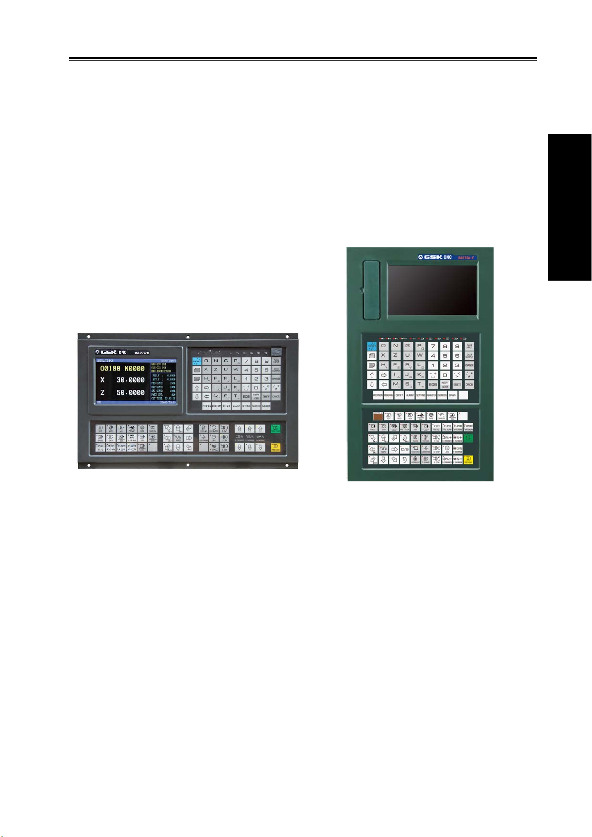
GSK980TDb GSK980TDb-V
th
X, Z, Y, 4
2ms interpolation period, control precision 1μm, 0.1μm
Max. speed 60m/min(up to 24m/min in 0.1μm)
Adapting to the servo spindle to realize the spindle continuously positioning, rigid tapping, and
the rigid thread machining
Built-in multi PLC programs, and the PLC program currently running can be selected
G71 supporting flute contour cycle cutting
Statement macro command programming, macro program call with parameter
Metric/inch programming, automatic toolsetting, automatic chamfer, tool life management
function
Chinese, English, Spanish, Russian display can be selected by parameters.
USB interface, U disc file operation, system configuration and software
2-channel 0V~10V analog voltage output, two-spindle control
1-channel MPG input, MPG function
41 input signals and 36 output signals
Appearance installation dimension, and command system are compatible with GSK980TDa
, 5th ; axis name and axis type of Y, 4th, 5th can be defined
3

1.1.2 Technical specification
Controllable axes
Controllable axes: 5(X, Z, Y , 4
Volum e Ⅰ Programming
Link axes:3
PLC controllable axes:3(X, Z, Y)
Feed axis function
Least input unit: 0.001mm(0.0001inch)and 0.0001mm(0.00001inch)
Least command unit:0.001mm(0.0001inch)and 0.0001mm(0.00001inch)
Position command range: ±99999999× least command unit
Rapid traverse speed:max. speed 60m/min in 0.001mm command unit, max. speed
24m/min in 0.0001mm command unit
Rapid override: F0, 25%, 50%, 100%
Feedrate override: 0~150% 16 grades to tune
Interpolation mode: linear interpolation, arc interpolation(three-point arc interpolation),
thread interpolation, ellipse interpolation, parabola interpolation and rigid tapping
Automatic chamfer function
GSK980TDb Turning CNC System User Manual
th,5th
)
Thread function
General thread(following spindle)/rigid thread
Single/multi metric, inch straight thread, taper thread, end face thread, constant pitch
thread and variable pitch thread
Thread run-out length, angle, speed characteristics can be set
Thread pitch: 0.01mm~500mm or 0.06 tooth/inch~2540 tooth/inch
Acceleration/deceleration function
Cutting feed: linear
Rapid traverse: linear, S
Thread cutting: linear, exponential
Initial speed, termination speed, time of acceleration/deceleration can be set by
parameters.
Spindle function
2-channel 0V~10V analog voltage output, two-spindle control
1-channel spindle encoder feedback, spindle encoder line can be set(100p/r~5000p/r)
Transmission ratio between encoder and spindle:(1~255):(1~255)
Spindle speed: it is set by S or PLC, and speed range: 0r/min~9999r/min
Spindle override: 50%~120% 8 grades tune
Spindle constant surface speed control
Rigid tapping
Tool function
Tool length compensation
Tool nose radius compensation(C)
Tool wear compensation
Tool life management
Toolsetting mode: fixed-point toolsetting, trial-cut toolsetting, reference point return
toolsetting, automatic toolsetting
4

Chapter 1 Programming
Tool offset execution mode: modifying coordinate mode, tool traverse mode
Precision compensation
Backlash compensation
Memory pitch error compensation
PLC function
Two-level PLC program,up to 5000 steps,the 1st program refresh period 8ms
PLC program communication download
PLC warning and PLC alarm
Many PLC programs(up to 16PCS), the PLC program currently running can be
selected
Basic I/O:41 input signals /36 output signals
Man-machine interface
7.4″ wide screen LCD,resolution: 234×480
Chinese, English, Spanish, Russian display
Planar tool path display
Real-time clock
Volum e Ⅰ Programming
Operation management
Operation mode: edit, auto, MDI, machine zero return, MPG/single, manual, program
zero return
Multi-level operation privilege management
Alarm record
Program edit
Program capacity: 40MB , 10000 programs ( including subprograms and macro
programs)
Edit function: program/block word search, modification, deletion
Program format: ISO command, statement macro command programming, relative
coordinate, absolute coordinate and compound coordinate programming
Program call: macro program call with parameter, 4-level program built-in
Communication function
RS232:two-way transmitting part programs and parameters, PLC program, system
software serial upgrade
USB:U file operation, U file directly machining, PLC program, system software U
upgrade
Safety function
Emergency stop
Hardware travel limit
Software travel check
Data backup and recovery
5
GSK980TDb Turning CNC System User Manual
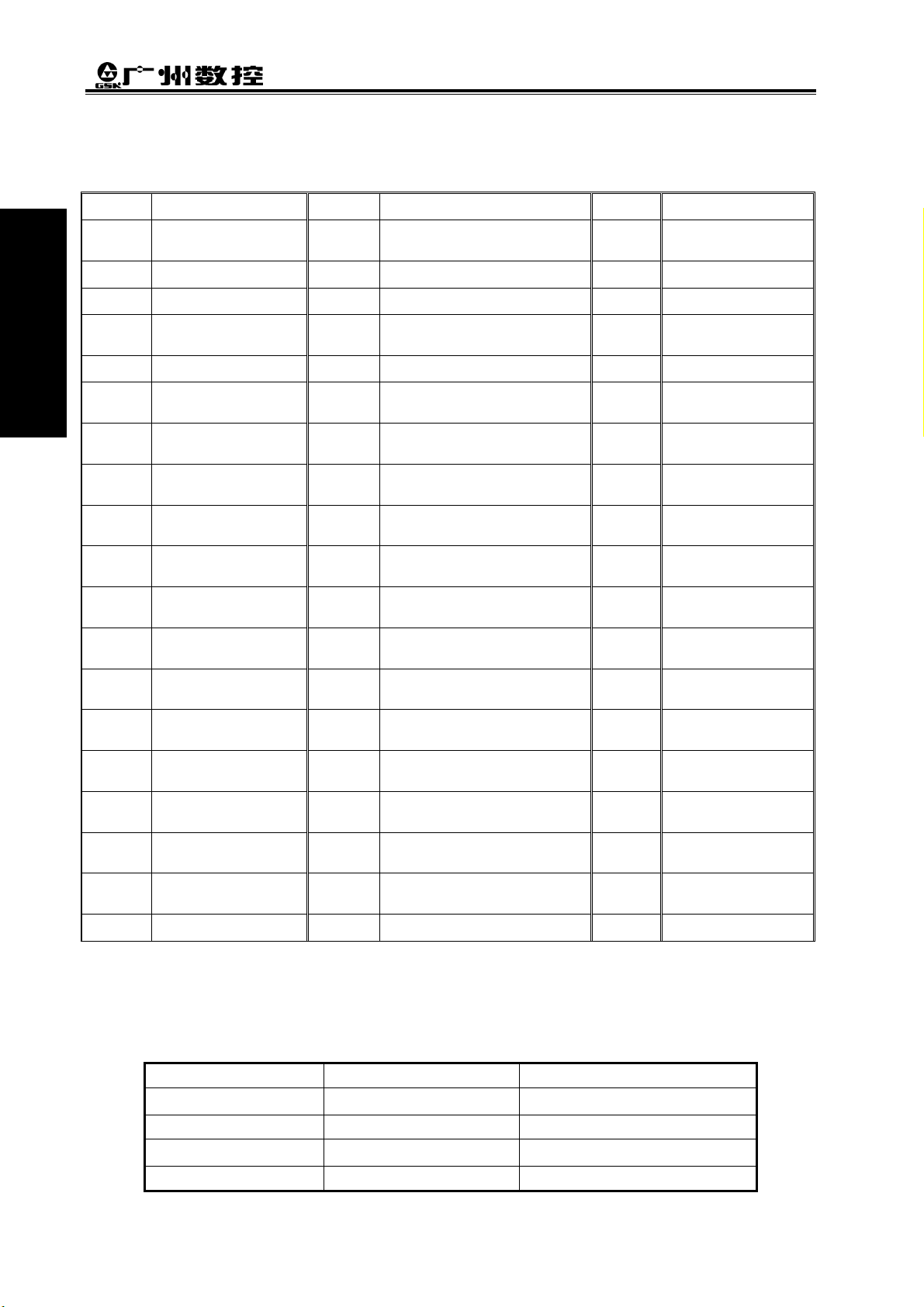
G command table
Table 1-1
Command Function Command Function Command Function
Volum e Ⅰ Programming
G00 Rapid traverse
G01
G02
G03
G04
G05
G6.2
G6.3
G7.2
G7.3
G12.1
G7.1
G15
G16
G17
G18
G19
G10
G11
G20
(positioning)
Linear interpolation
CW arc interpolation
CCW arc interpolation G30
Dwell, exact stop
Three-point arc
interpolation
Ellipse interpolation
(CW)
Ellipse
interpolation(CCW)
Parabola
interpolation(CW)
Parabola
interpolation(CCW)
Polar coordinate
interpolation
Cylinder interpolation
Polar coordinate
command cancel
Polar coordinate
command
Plane selection
command
Plane selection
command
Plane selection
command
Data input ON
Data input OFF
G21
G28
G31
G32
G32.1
G33
G34 Thread cutting with variable
G36
G37
G40 Tool nose radius compensation
G41 Tool nose radius compensation
G42 Tool nose radius compensation
G50 Workpiece coordinate system
G65 Macro command non-modal
G66 Macro program modal call
G67 Macro program modal call
G71
Input in inch
Input in metric
Reference point return
2nd, 3rd, 4threference point
return
Skip function
Constant pitch thread cutting
Rigid thread cutting
Z tapping cycle
lead
Automatic tool compensation X
Automatic tool compensation Z
cancel
left
right
setting
call
cancel
Axial roughing cycle(flute cycle)
G72
G73
G70
G74
G75
G76
G80
G84
G88
G90
G92
G94
G96
G97
G98
G99
Radial roughing cycle
Closed cutting cycle
Finishing cycle
Axial grooving cycle
Radial grooving cycle
Multiple thread cutting
cycle
Rigid tapping state
cancel
Axial rigid tapping
Radial rigid tapping
Axial cutting cycle
Thread cutting cycle
Radial cutting cycle
Constant surface speed
control
Constant surface speed
control cancel
Feed per minute
Feed per revolution
1.1.3 Environment and conditions
GSK980TDb storage delivery, working environment as follows:
Table 1-2
Item Working conditions Storage delivery conditions
Ambient temperature
Ambient humidity ≤90%(no freezing) ≤95%(40 )℃
Atmosphere pressure
Altitude ≤1000m ≤1000m
6
0℃~45℃ -40℃~+70℃
86 kPa~106 kPa 86 kPa~106 kPa

Chapter 1 Programming
1.1.4 Power supply
GSK980TDb can normally run in the following AC input power supply.
Voltage: within(0.85~1.1)×rated AC input voltage (AC 220V);
Frequency: 49Hz~51Hz continuously changing
1.1.5 Guard
GSK980TDb guard level is not less than IP20.
1.2 CNC system of machine tools and CNC machine tools
CNC machine tool is an electro-mechanical integrated product, composed of Numerical Control
Systems of Machine Tools, machines, electric control components, hydraulic components, pneumatic
components, lubricant, cooling and other subsystems (components), and CNC systems of machine
tools are control cores of CNC machine tools. CNC systems of machine tools are made up of
computerized numerical control(CNC), servo (stepper) motor drive devices, servo (or stepper) motor
etc.
Operational principles of CNC machine tools: according to requirements of machining
technology, edit user programs and input them to CNC, then CNC outputs motion control commands
to the servo (stepper) motor drive devices, and last the servo (or stepper) motor completes the cutting
feed of machine tool by mechanical driving device; logic control commands in user programs to
control spindle start/stop, tool selections, cooling ON/OFF, lubricant ON/OFF are output to electric
control systems of machine tools from CNC, and then the electric control systems control output
components including buttons, switches, indicators, relays, contactors and so on. Presently, the
electric control systems are employed with Programmable Logic Controller (PLC) with characteristics
of compact, convenience and high reliance. Thereof, the motion control systems and logic control
systems are the main of CNC machine tools.
GSK980TDb Turning Machine CNC system has simultaneously motion control and logic control
function to control two axes of CNC machine tool to move, and has nested PLC function. Edit PLC
programs (ladder diagram) according to requirements of input and output control of machine tool and
then download them to GSK980TDb Turning Machine CNC system, which realizes the required
electric control requirements of machine tool, is convenient to electric design of machine tool and
reduces cost of CNC machine tool.
Software used to control GSK980TDb Turning Machine CNC system are divided into system
software (NC for short) and PLC software (PLC for short). NC system is used to control the display,
communication, edit, decoding, interpolation and acceleration/deceleration, and PLC system for
controlling explanations, executions, inputs and outputs of ladder diagrams.
Standard PLC programs are loaded (except for the special order) when GSK980TDb Turning
Machine CNC System is delivered, concerned PLC control functions in following functions and
operations are described according to control logics of standard PLC programs, marking with
“Standard PLC functions” in GSK980TDb Turning CNC System User Manual. Refer to Operation
Manual of machine manufacturer about functions and operations of PLC control because the
machine manufacturer may modify or edit PLC programs again.
Volum e Ⅰ Programming
7
GSK980TDb Turning CNC System User Manual
Volum e Ⅰ Programming
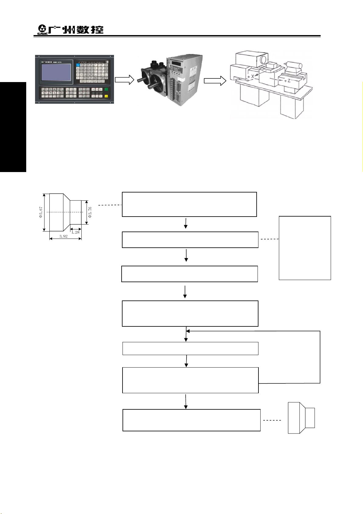
Fig. 1-1
Programming is a course of workpiece contours, machining technologies, technology
parameters and tool parameters being edit into part programs according to special CNC
programming G codes. CNC machining is a course of CNC controlling a machine tool to complete
machining of workpiece according requirements of part programs.
Technical flow of CNC machining is as following Fig. 1-2.
Analyse workpiece drawings and confirm
machining processing
O0001;
G00 X3.76 Z0;
Edit part programs and record into CNC
Test part programs and execute trial run
G01 Z-1.28 F50;
…
M30;
%
Execute toolsetting and set tool offsets and
coordinates
Run part programs and machine workpiece
Check part dimension and modify part
programs and compensations
The machining ends and the workpiece is
formed
Fig. 1-2
8
1.3 Programming fundamentals
1.3.1 Coordinates definition
Chapter 1 Programming
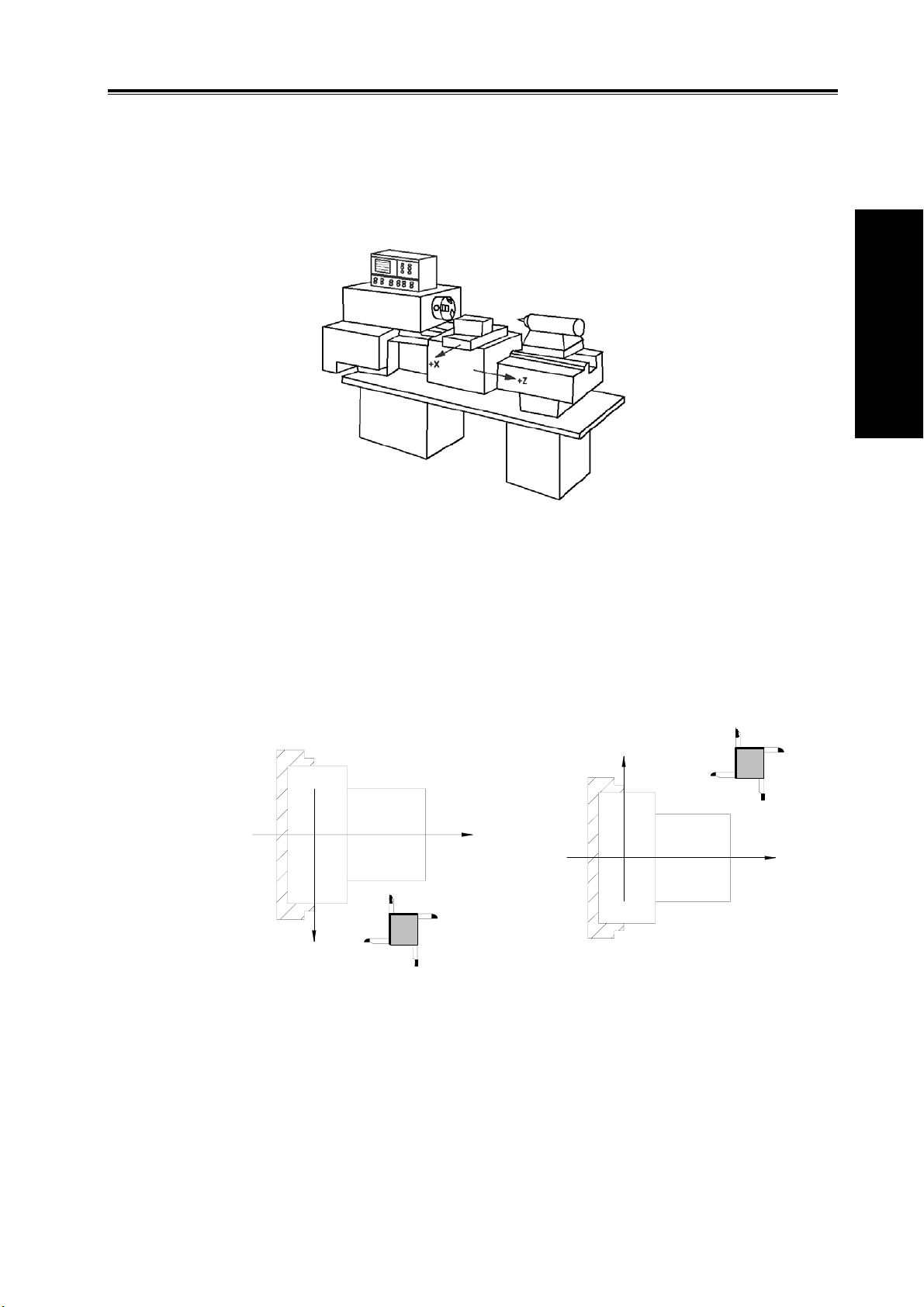
Sketch map of CNC turning machine is as follows:
Fig. 1-3
GSK980TDb uses a rectangular coordinate system composed of X, Z axis. X axis is
perpendicular with axes of spindle and Z axis is parallel with axes of spindle; negative directions of
them approach to the workpiece and positive ones are away from it.
There is a front tool post and a rear tool post of NC turning machine according to their relative
position between the tool post and the spindle, Fig. 1-5 is a coordinate system of the front tool post
and Fig. 1-6 is a rear tool post one. It shows exactly the opposite of X axes, but the same of Z axes
from figures. In the manual, it will introduce programming application with the front tool post
coordinate system in the following figures and examples.
Volum e Ⅰ Programming
X
Z
Z
X
Fig.1-4 Front tool post coordinate system Fig.1-5 Rear tool post coordinate system
1.3.2 Machine coordinate system, Machine Zero and machine reference
point
Machine tool coordinate system is a benchmark one used for CNC counting coordinates and a
fixed one on the machine tool. Machine tool zero is a fixed point which position is specified by zero
switch or zero return switch on the machine tool. Usually, the zero return switch is installed on max.
stroke in X, Z positive direction. Machine reference point is located at the position at which the
9
GSK980TDb Turning CNC System User Manual
machine zero value adding the data parameter No.114/No.115 value. When No.114/No.115 value is 0,
the machine reference point coincides with the machine zero. The coordinates of machine reference
point is the No.120/No.121 value. Machine zero return/G28 zero return is to execute the machine
reference point return. After the machine zero return/machine reference point return is completed,
Volum e Ⅰ Programming
GSK980TDb machine coordinate system which takes No.120/No.121 value as the reference point.
Note: Do not execute the machine reference point return without the reference point switch installed on the
machine tool, otherwise, the motion exceeds the travel limit and the machine to be damaged.
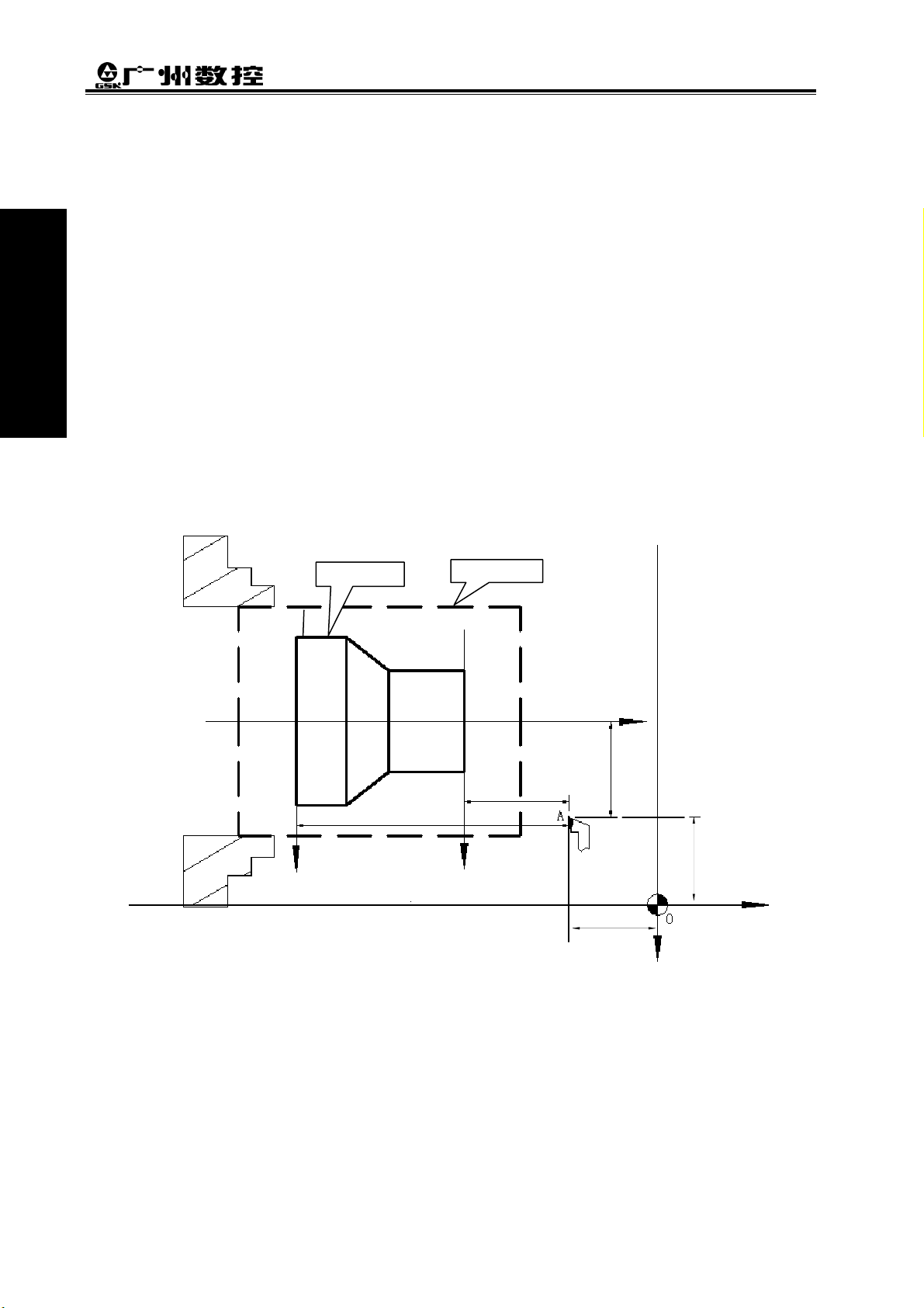
1.3.3 Workpiece coordinate system and Program Zero
The workpiece coordinate system is a rectangular coordinate system based on the part drawing,
also called floating coordinate system. After the workpiece is installed on the machine, the absolute
coordinates of tool’s current position is set by G50 according to the workpiece’s measure, and so the
workpiece coordinate system is established in CNC. Generally, Z axis of the workpiece coordinate
system coincides with the spindle axis. The established workpiece is valid till it is replaced by a new
one.
The current position of workpiece coordinate system set by G50 is the program zero.
Note: Do not execute the machine reference point return without using G50 to set the workpiece coordinate
system after power on, otherwise, the alarm occurs.
Workpiece
O2
z
2
Rod
O
1
Z1 (Z2)
x
/2 (x2/2)
1
z
1
(x,z)
X2
X
1
(x
1,z1
2,z2
)
X/2
)
(x
Z
(0,0)
Z
Fig. 1-6
In the above figure, XOZ is the coordinate system of machine tool, X
coordinate system of X axis located at the heading of workpiece, X
is the one of X axis located
2O2Z2
at the ending of workpiece, O point is the machine reference point, A point is the tool nose and
coordinates of A point in the above-mentioned coordinate systems is as follows:
A point in the machine tool coordinate system: (x,z);
A point in X
A point in X
coordinate system: (x1,z1);
1O1Z1
coordinate system: (x2,z2).
2O2Z2
X
is the workpiece
1O1Z1
10
Chapter 1 Programming
1.3.4 Interpolation function
Interpolation is defined as a planar or three dimensional contour formed by path of 2 or multiple
axes moving at the same time, also called Contour control. The controlled moving axis is called link
axis when the interpolation is executed. The moving distance, direction and speed of it are controlled
synchronously in the course of running to form the required Composite motion path. Positioning
control is defined that motion end point of one axis or multiple axes instead of the motion path in the
course of running is controlled.
GSK980TDb X and Z axis are link axes and 2 axes link CNC system. The system possesses
linear, circular and thread interpolation function.
Linear interpolation: Composite motion path of X, Z axis is a straight line from starting point to
end point.
Circular interpolation: Composite motion path of X, Z axis is arc radius defined by R or the circle
center (I, K) from starting point to end point.
Thread interpolation: Moving distance of X or Z axis or X and Z axis is defined by rotation angle
of spindle to form spiral cutting path on the workpiece surface to realize the
thread cutting. For thread interpolation, the feed axis rotates along with the
spindle, the long axis moves one pitch when the spindle rotates one rev,
and the short axis and the long axis directly interpolate.
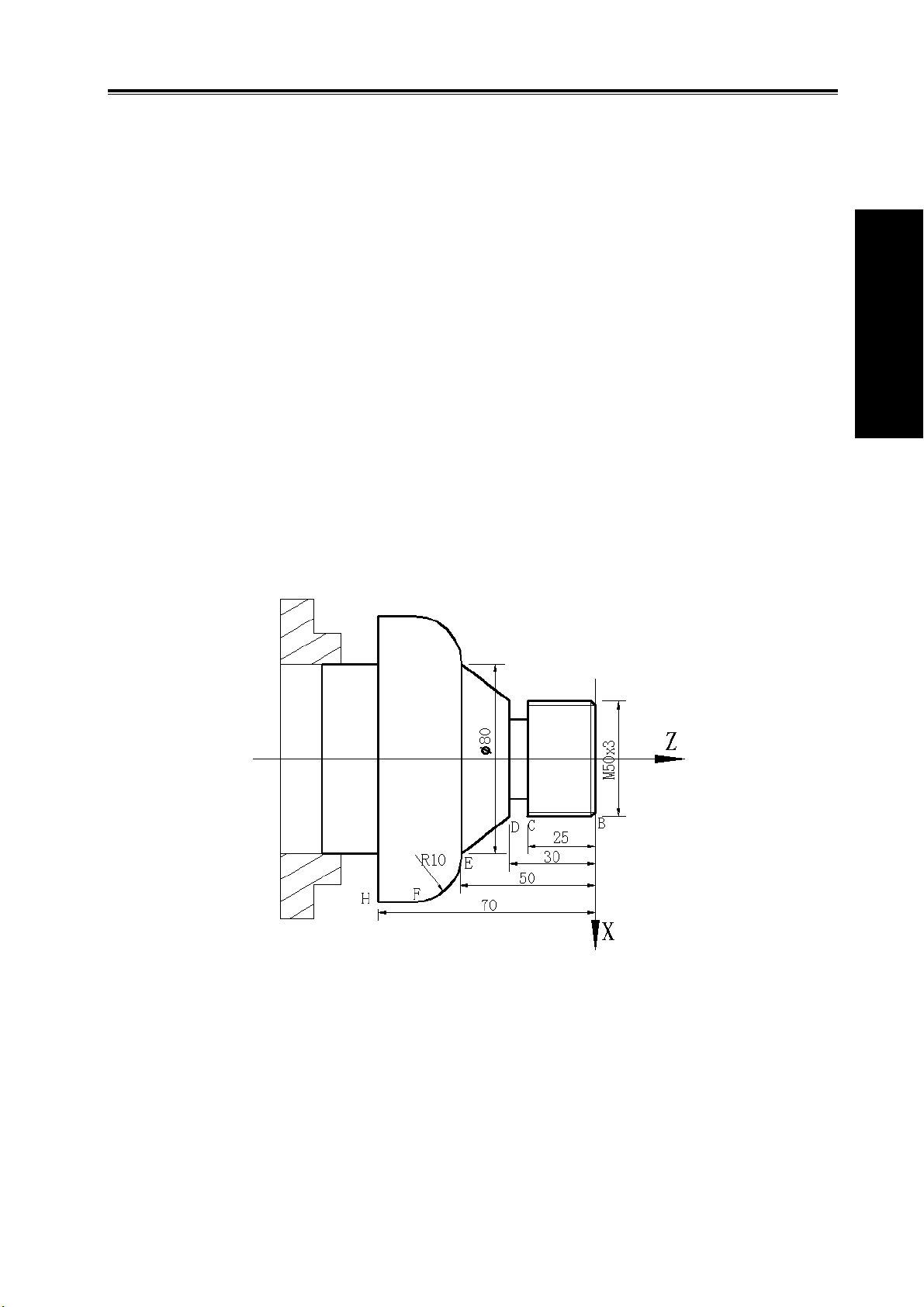
Example:
Volum e Ⅰ Programming
Fig. 1-7
…
G32 W-27 F3; (B→C; thread interpolation)
G1 X50 Z-30 F100;
G1 X80 Z-50; (D→E; linear interpolation)
G3 X100 W-10 R10; (E→F; circular interpolation)
…
M30;
11
Loading…
#1
OFFLINE
Zombie47
- Пользователи
- 6 сообщений
Абитуриент
- Из:Санкт-Петербург
Отправлено 08 Февраль 2015 — 05:40
Всем привет. Появилась возможность поучиться поработать на токарном ЧПУ станке GSK980TDb.
10 лет назад учился в колледже на технолога машиностроения. Как раз на специальность написание технологии обработки детали. А так же написание программ на G коде.
Но никогда по этой специальности не работал. Да и забыл многое, придется вспоминать.
Вообщем сейчас проблема в том что не хватает знаний связать все воедино.
Раньше мы писали программы для обработки детали вручную, сейчас я уже не помню все тонкости написания и вижу есть программы которые впринципе все делают гораздо проще.
Как я понимаю процесс таков:
1. Создание 3д модели по чертежам (с 3д работать умею проблем нет)
2. Написание программы для станка с ЧПУ. Я это решил делать через FeatureCAM. (есть проблемки но в целом принцип понятен.) Основная проблема столкнулся с тем что для выведения G кода нужен какой то постпроцессор. И как я понимаю нужен он под конкретный станок. Куда копать? Где взять? что нужно знать?
3. Далее чтобы не убить станок и тд я скачал CNC Simulator и там есть похожий станок GSK980TD на котором я бы мог попробывать изготовить деталь по моей программе. (Есть проблемы и в конкретном станке в тексте много вопросиков и иероглифов)
4. Если освою симулятор то думаю уже можно на реальном станке пробывать что то делать, думая над такими вещами как правильный ли резец выбрал, правильную ли глубину прохода взял и тд.
Может тут мне помогут в моем не легком деле? =)
-
0
- Наверх
#2
OFFLINE
sum@r
sum@r
- Пол:Мужчина
- Город:Стерлитамак
- Интересы:Фануковед,кладоискатель
- Из:Стерлитамак
Отправлено 09 Февраль 2015 — 10:59
Если металлообработка, то на токарном с 3д моделями лучше не заморачивайся. После постпроцессора дольше будешь редактировать, чем новую писать. Скачай проггу СIMCOEdit-6 и пробуй в нем.
Сообщение отредактировал sum@r: 09 Февраль 2015 — 11:01
-
0
- Наверх
#3
OFFLINE
Zombie47
Zombie47
- Пользователи
- 6 сообщений
Абитуриент
- Из:Санкт-Петербург
Отправлено 10 Февраль 2015 — 04:05
Спасибо уже что то, первая помощь из вне =))) Скачаю попробую, упрусь в проблему напишу.
Есть еще вопрос по наладке станка. Как я понимаю я станку должен дать понять где точка старта от которой пойдет программа. Вроде называется нуль станка. Это задается в программе или в станке как то? А так же знаю есть офсеты иснтрументов, вылет инструментов, но не очень помню как это реализуется. Вплане есть же отрезной резец а есть проходной. Так вот у них относительно зажима инструмента разная точка где будет контактировать резец с деталью. Куда копать что читать? Наладку станка? или наладка инструмента?
-
0
- Наверх
#4
OFFLINE
Zombie47
Zombie47
- Пользователи
- 6 сообщений
Абитуриент
- Из:Санкт-Петербург
Отправлено 10 Февраль 2015 — 14:45
Как я понял CIMCO Edit это просто блокнот с возможностью визуализации. Мне не совсем просто писать программу так как кучу всего не понятно. Например какие координаты надо ставить для G54 при наладке. Везде пишут разное, то расстояние от нуля до револьверной головке, то расстояние до заготовки. Вообщем не понятно. Да и не понятно сколько проходов делать какой глубины, так как я этого не помню. Получается надо пользоваться прогой Feature CAM для уточнения этих моментов или интернетом. Например для нержавейки нужен свой резец свои обороты и своя глубина прохода и своя подача.
-
0
- Наверх
#5
OFFLINE
Zombie47
Zombie47
- Пользователи
- 6 сообщений
Абитуриент
- Из:Санкт-Петербург
Отправлено 11 Февраль 2015 — 01:04
Как мне начать писать программу если я не знаю сколько по координатам мне идти до заготовки. Как вообще это правильно делается? В идеале я понимаю мне нужен инструмент которым я мягко упрусь в заготовку в центр и дам понять станку что вот центр заготовки, а дальше вылет инструментов диаметр заготовки и тд. Есть от чего плясать.
-
0
- Наверх
#6
OFFLINE
Ryoji
Ryoji
- Пол:Мужчина
- Из:Калининград
Отправлено 25 Январь 2019 — 00:59
Уважаемы, подскажите с каких книг начать изучение работы на токарном чпу (Fanuc Doosan серии lynx). Дело в том что с токарной обработкой совершено не знаком, но работал на 3х осевых фрезерах на раскрое материала. Дайте пожалуйста совет как и с чего начать что бы быстрее освоится.
-
0
- Наверх
#7
OFFLINE
2ar
2ar
- Пол:Мужчина
- Город:Новосибирск
- Интересы:Сервисное обслуживания станков
- Из:Новосибирск
Отправлено 25 Январь 2019 — 06:48
С теории токарной обработки
-
0
- Наверх
#8
OFFLINE
SNB
SNB
- Пол:Мужчина
- Город:Подольск
- Из:Подольск
Отправлено 25 Январь 2019 — 07:48
Определитесь с чем Вам помочь. Моделирование (это для Вас не проблема), написание программы и собственно металлообработка — это смежные, но все-таки разные вещи. Конечно, в идеале, это все должен делать один человек.
По-моему, для токарки программирование лучше сразу вручную в G-кодах делать. Хотя знаю человека, который с Solid постпроцессором сразу в станок проги грузил. Кому как. В свое время в нете покупал книгу «Руководство программиста». Правда некоторых страниц все-равно не хватает, но для программирования хватило, даже с избытком. Так там в книге по инструментам и режимам резания ничего не говорится. Если интересует книга, то обращайтесь. Страницу с содержанием прикладываю. Может она уже и в свободном доступе есть.
-
0
- Наверх