

PR 30-HVS
Bedienungsanleitung de
Operating instructions en
Mode d’emploi fr
Istruzioni d’uso it
Manual de instrucciones es
Manual de instruções pt
Gebruiksaanwijzing nl
Brugsanvisning da
Bruksanvisning sv
Bruksanvisning no
Käyttöohje
Οδηγιεςχρησεως el
Használati utasítás hu
Instrukcjaobsługi pl
Инструкцияпозксплуатации ru
Návod k obsluze cs
Návod na obsluhu sk
Upute za uporabu hr
Navodila za uporabo sl
Printed: 29.11.2013 | Doc-Nr: PUB / 5142593 / 000 / 02
1
௺௹
Printed: 29.11.2013 | Doc-Nr: PUB / 5142593 / 000 / 02
2
௹
௺
3
4
௹
௹
௺
5
6
௺
ఁ
ఀ
௺
௹
Printed: 29.11.2013 | Doc-Nr: PUB / 5142593 / 000 / 02
ఀ
௺
௹
7
8
௺
௹
9
Printed: 29.11.2013 | Doc-Nr: PUB / 5142593 / 000 / 02
35$ 35$ 35$
10
11
[
12
$
14
Printed: 29.11.2013 | Doc-Nr: PUB / 5142593 / 000 / 02
13
%
$
15
%
[
[
16
17
P
P
P
D
E
P
F G
%
5
Printed: 29.11.2013 | Doc-Nr: PUB / 5142593 / 000 / 02
P
$
P
18
PP
&
%
$
P
5
Printed: 29.11.2013 | Doc-Nr: PUB / 5142593 / 000 / 02

ORIGINAL OPERATING INSTRUCTIONS
PR 30-HVS rotating laser
It is essential that the operating instructions
are read before the tool is operated for the
en
first time.
Always keep these operating instructions to-
gether with the tool.
Ensure that the operating instructions are
with the tool when it is given to other persons.
Contents Page
1 General information 23
2Description 23
3 Accessories 26
4 Technical data 26
5 Safety instructions 28
6Beforeuse 30
7 Operation 31
8 Care and maintenance 38
9 Troubleshooting 39
10 Disposal 40
11 Manufacturer’s warranty — tools 41
12 FCC statement (applicable in US) / IC
statement (applicable in Canada) 41
13 EC declaration of conformity (original) 42
1 These numbers refer to the corresponding illustrations. The illustrations can be found on the fold-out cover
pages. Keep these pages open while studying the operating instructions.
In these operating instructions, the designation “the tool”
or “the rotating laser” always refers to the PR 30-HVS.
“Remote control”, “laser receiver” or «receiver» always
refer to the PRA 30 (03).
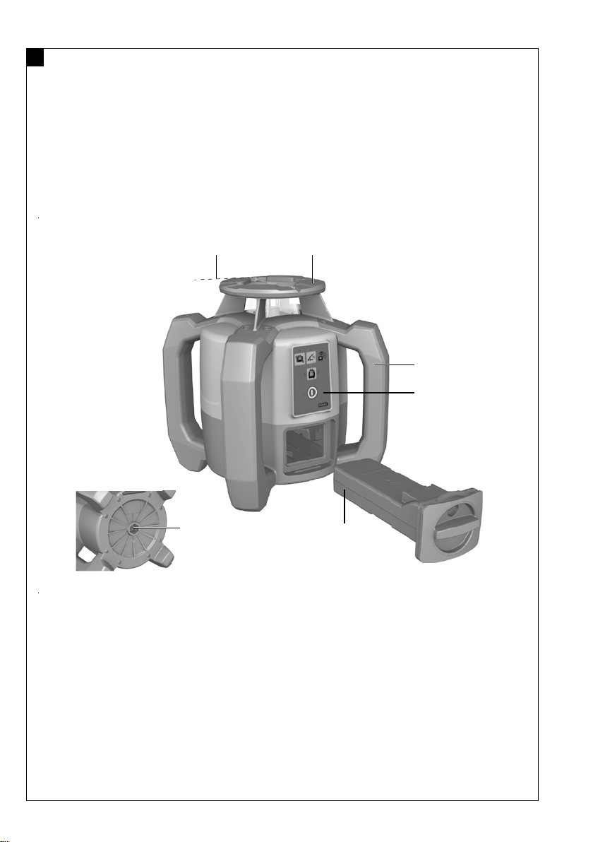
Rotating laser 1
Laser beam (plane of rotation)
@
Rotating head
;
Grip
=
Control panel
%
Base plate with ⁵/₈» thread
&
PRA 84 Li‑ion battery
(
Inserting and removing the battery 2
PRA 84 Li‑ion battery
@
Battery compartment
;
Catch
=
Charging the battery in the tool 3
PUA 81 AC adapter
@
Charging socket
;
Charging the battery after removal from the tool 4
PUA 81 AC adapter
@
PUA 82 motor vehicle power adapter
;
Charging activity LED
=
Rotating laser control panel 5
On/off button
@
Auto-leveling LED
;
LED arrow for electronic inclination alignment
=
Electronic inclination alignment button (only in con-
%
junction with inclined plane mode)
Shock warning function button and LED
&
Inclined plane mode button and LED
(
Surveillance mode LED (only with automatic vertical
)
alignment)
Battery charge status LED
+
PRA 30 control panel 6
On/off button
@
Inclination entry button (Plus / Right or Up arrow
;
button) (with the PRA 90)
Units button
=
Volume button
%
Inclination entry button (Minus / Left or Down arrow
&
button) (with the PRA 90:
Automatic alignment / surveillance mode button
(
(vertical) (double click)
Receiving window
)
Marking notch
+
Display
§
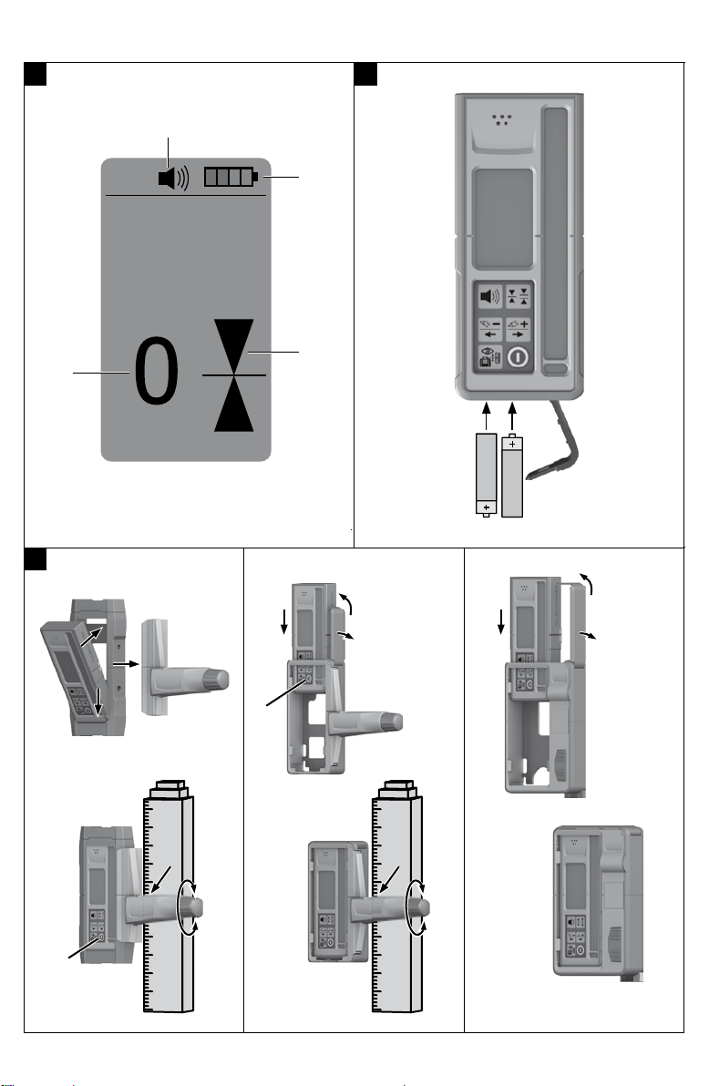
PRA 30 display 7
Display showing the position of the receiver relative
@
to the height of the laser plane
Battery status
;
Volume
=
Indication of distance from laser plane
%
22
1 General information
1.1 Safety notices and their meaning
DANGER
Draws attention to imminent danger that will lead to
seriousbodilyinjuryorfatality.
WARNING
Draws attention to a potentially dangerous situation that
could lead to serious personal injury or fatality.
CAUTION
Draws attention to a potentially dangerous situation that
could lead to slight personal injury or damage to the
equipment or other property.
NOTE
Draws attention to an instruction or other useful information.
1.2 Explanation of the pictograms and other
information
Symbols
On the tool
Laser Class 2 in accordance with IEC/EN 60825‑1:2007
On the tool
&$87,21
/$6(55$’,$7,21’2127
67$5(,172%($0
QP3R P:Ă530
&/$66,,/$6(5352’8&7
Laser Class II according to CFR 21, § 1040 (FDA)
Location of identification data on the tool
The type designation and serial number can be found on
thetypeidentificationplateonthetool.Makeanoteof
this data in your operating instructions and always refer
to it when making an enquiry to your Hilti representative
or service department.
Type:
Generation: 01
en
Read the
operating
instructions
before use.
For indoor
use only
General
warning
Return waste
material for
recycling.
Warning:
caustic
substances
Do not look
into the
beam.
Warning:
electricity
Warning:
explosive
substances
Serial no.:
2 Description
2.1 Use of the product as directed
The Hilti PR 30-HVS is a rotating laser tool with a visible rotating laser beam and a reference beam set at 90° to the
main beam. The rotating laser can be used vertically, horizontally and for inclined planes.
The tool is designed to be used to determine, transfer and check levels, verticals, slopes and right angles. Examples of
its uses are: transferring datums and height marks, determining right angles for walls, vertical alignment on reference
points and setting out slopes.
The tool is designed for professional use and may be operated, serviced and maintained only by trained, authorized
personnel. This personnel must be informed of any special hazards that may be encountered. The tool and its ancillary
equipment may present hazards when used incorrectly by untrained personnel or when used not as directed.
Hilti supplies various accessories which allow the tool to be used with maximum efficiency.
To avoid the risk of injury, use only genuine Hilti accessories and insert tools.
Observe the information printed in the operating instructions concerning operation, care and maintenance.
Take the influences of the surrounding area into account. Do not use the appliance where there is a risk of fire or
explosion.
Modification of the tool is not permissible.
23
PR 30-HVS A12
English 1 20 Romn 40 Trke 59
79
Latvieu 100 Lietuvi 119 Eesti 138 157 178 199 218 236 252
*2134494* 2134494 English 1
Original operating instructions
1 Information about the operating instructions
1.1 About these operating instructions
Read these operating instructions before the product is used or operated for the first time. This is a prerequisite for safe, trouble-free handling and use of the product.
Observe the safety instructions and warnings in these operating instructions and on the product. Always keep the operating instructions with the product and make sure that the product is accompanied
by these operating instructions only, when the product is given to other persons.
1.2 Explanation of symbols used
1.2.1 Warnings
Warnings alert persons to hazards that occur when handling or using the product. The following signal words are used:
DANGER DANGER ! Draws attention to imminent danger that will lead to serious personal injury or fatality.
WARNING WARNING ! Draws attention to a potential threat of danger that can lead to serious injury or fatality.
CAUTION CAUTION ! Draws attention to a potentially dangerous situation that could lead to personal injury or damage to the
equipment or other property.
1.2.2 Symbols in the documentation
The following symbols are used in this document:
Read the operating instructions before use.
Instructions for use and other useful information
Dealing with recyclable materials
Do not dispose of electric equipment and batteries as household waste
1.2.3 Symbols in the illustrations
The following symbols are used in illustrations:
These numbers refer to the corresponding illustrations found at the beginning of these operating instructions
The numbering reflects the sequence of operations shown in the illustrations and may deviate from the steps described in the text
Item reference numbers are used in the overview illustrations and refer to the numbers used in the product overview section
This symbol is intended to draw special attention to certain points when handling the product.
2 English 2134494
*2134494*
1.3 Product-dependent symbols
1.3.1 Symbols on the product
The following symbols can be used on the product:
The product supports wireless data transmission compatible with iOS and Android platforms.
Hilti Li-ion battery type series used. Observe the information given in the section headed Intended use.
Li-ion battery
Never use the battery as a striking tool.
Do not drop the battery. Never use a battery that has suffered an impact or is damaged in any other way.
1.4 On the product
Laser information
Laser class 2 based on standard IEC60825-1 / EN60825-1:2007 and compliant with CFR 21 1040 (Laser Notice 50). Do not look straight into the laser beam.
1.5 Product information
products are designed for professional users and only trained, authorized personnel are permitted to operate, service and maintain the products. This personnel must be specifically informed about the possible hazards. The product and its ancillary equipment can present hazards if used incorrectly by untrained personnel or if used not in accordance with the intended use. The type designation and serial number are printed on the rating plate. Write down the serial number in the table below. You will be required to state the product details when
contacting Hilti Service or your local Hilti organization to inquire about the product. Product information
Rotating laser PR 30-HVS A12
Generation 02
Serial no.
Product information
Rotating laser PRA 30
Generation 03
Serial no.
1.6 Declaration of conformity
We declare, on our sole responsibility, that the product described here complies with the applicable directives and standards. A copy of the declaration of conformity can be found at the end of this documentation. The technical documentation is filed here: Hilti Entwicklungsgesellschaft mbH | Tool Certification | Hiltistrasse 6 | D-86916 Kaufering, Germany
2 Safety
2.1 Basic information concerning safety
Read all safety instructions and other instructions. Failure to observe the safety instructions and other instructions may result in electric shock, fire and/or serious injury. Retain all safety precautions and instructions for future reference. The term electric tool used in the safety instructions refers to your mains-operated (corded) electric tool or battery-operated (cordless) electric tool.
*2134494* 2134494 English 3
2.2 General safety measures
Stay alert, watch what you are doing and use common sense when operating a power tool. Do not use a power tool while you are tired or under the influence of drugs, alcohol or medication. A moment of inattention while operating the power tool can result in serious personal injury.
Do not render safety devices ineffective and do not remove information and warning notices. Keep children well away from laser devices. Laser radiation in excess of Class 2 may be emitted if the device is opened without following the correct
procedures. Have the device repaired only by Hilti Service. Project laser beams well above or well below eye height. Take the influences of the surrounding area into account. Do not use the device where there is a
risk of fire or explosion. Statement in accordance with FCC 15.21: Changes or modifications not expressly approved by Hilti
can restrict the users authorization to operate the equipment. You must check the accuracy of the device after it has been dropped or subjected to other
mechanical stresses. When the device is brought into a warm environment from very cold conditions, or vice-versa,
allow it to become acclimatized before use. When using adapters or accessories, make sure that the equipment is securely mounted. Keep the laser aperture clean to avoid measurement errors. The device is designed for the tough conditions of jobsite use, but as with other optical and
electronic instruments (e.g. binoculars, spectacles, cameras) it must be handled with care. The device is protected to prevent the ingress of moisture, but you must always wipe it dry before
stowing it in the transport container. Check the device before using it for important measuring work. Repeatedly check accuracy while using the device. Make sure that the workplace is well lit. Do not expose the laser to rain or wet conditions. Do not touch the contacts. Maintain the device carefully. Check that moving parts are in full working order and do not jam
and make sure there are no parts that are broken or damaged in such a way as to impair operation of the device. If it damaged, have the device repaired before use. Many accidents are caused by poorly maintained equipment.
2.3 Proper preparation of the working area
Secure the area in which you will be taking measurements. Make sure that the laser beam is not directed toward other persons or toward yourself while setting up the laser tool.
Avoid unfavorable body positions when working from ladders. Make sure you work from a safe stance and stay in balance at all times.
Readings taken in the vicinity of reflective objects or surfaces, through panes of glass or similar materials may produce incorrect results.
Ensure that the tool is set up on a stable, level surface (not subject to vibration). Use the tool only within its specified limits. Use the tool and its accessories etc. in accordance with these instructions and in the manner
intended for the particular type of tool. Take the working conditions and the work to be performed into account. Use of tools for applications different from those intended could result in a hazardous situation.
Use of the telescopic staff in the vicinity of overhead high voltage cables is not permissible.
2.4 Electromagnetic compatibility
Although the tool complies with the strict requirements of the applicable directives, Hilti cannot exclude the following possibilities:
The tool may be negatively affected by powerful electromagnetic radiation, possibly leading to incorrect operation. In these cases, or if you are otherwise unsure, confirmatory measurements should be made by other means.
The tool can cause interference to other devices (e.g. aircraft navigation equipment).
4 English 2134494
*2134494*
2.5 Laser classification for Class 2 laser products
The tool complies with laser Class 2 as per IEC60825-1:2007 / EN60825-1:2007. This tool may be used without need for further protective measures.
CAUTION Risk of injury! Do not direct the laser beam toward persons. Never look directly into the source of the laser beam. In the event of direct eye contact, close your eyes
and move your head out of the path of the laser beam.
2.6 Careful use of battery-powered tools
Do not expose batteries to high temperatures, the direct heat of the sun, and keep them away from fire. There is a risk of explosion.
Do not disassemble, squash or incinerate batteries and do not subject them to temperatures over 80C (176F). This presents a risk of fire, explosion or injury through contact with caustic substances.
Do not subject the battery to hard mechanical impacts and do not throw the battery. Batteries must be kept out of reach of children. Avoid ingress of moisture. Ingress of moisture may cause a short circuit, resulting in burning injuries or
fire. Under abusive conditions, liquid may leak from the battery. Avoid contact with the liquid. If contact
accidentally occurs, flush with water. If the liquid contacts the eyes, also seek medical attention. Liquid leaking from the battery may cause irritation or burns.
Use only batteries of the type approved for use with the applicable tool. Use of other batteries or use of the batteries for purposes for which they are not intended presents a risk of fire and explosion.
Store the battery in a cool and dry place. Never store the battery where it is exposed to direct sunlight or sources of heat, e.g. on heaters / radiators or behind glass.
When not in use, keep the battery and the charger away from paper clips, coins, keys, nails, screws or other small metal objects that could cause a short circuit at the battery terminals or the charging contacts. Short-circuiting the contacts on a battery or charger may cause burning injuries or start a fire.
Do not charge or continue to use damaged batteries (e.g. batteries with cracks, broken parts, bent or pushed-in and/or pulled-out contacts).
Recharge only with the charger specified by the manufacturer. A charger that is suitable for a certain type of battery may present a risk of fire when used with other types of battery.
Observe the special guidelines applicable to the transport, storage and use of Li-ion batteries. The battery must be insulated or removed from the tool before the tool is shipped or sent by mail.
Leaking batteries may damage the tool. If the battery gets noticeably hot when not in use, this may indicate that the battery or the tool / battery
system is faulty. In this case, place the tool in a non-flammable location, well away from flammable materials, where it can be kept under observation and allowed to cool down.
*2134494* 2134494 English 5
3 Description
3.1 Product overview
3.1.1 PR 30-HVS rotating laser 1
@ Laser beam (plane of rotation)
; Rotary head
= Sight
% Grip
& Battery release button
( Liion battery
) Battery state-of-charge display
+ Control panel
Base plate with 5/8″ thread
3.1.2 PR 30-HVS control panel 2
@ Inclined plane mode button and LED
; Shock warning function button and LED
= LED arrow for electronic inclination align- ment
% Electronic inclination alignment button (only in combination with inclined plane mode)
& Auto-leveling LED
( On/off button
) Surveillance mode LED (only with auto- matic vertical alignment)
+ Battery charge status LED
3.1.3 PRA 30 laser receiver and control panel 3
@ Volume button
; Negative inclination to the left or downward with PRA 90
= Automatic alignment / surveillance mode in the vertical plane (double-click)
% Units key
& Positive inclination to the right or upward with PRA 90
( On/off button
) Display
+ Marking notch
Detection area
3.1.4 PRA 30 laser receiver display 4
@ Indicator showing distance from laser plane
; Volume indicator
= Units key
% Detection area
& Marking notch
3.1.5 Intended use
The product described is a rotating laser with a visible rotating laser beam. It can be operated by one person. The tool is designed to be used to determine, transfer and check levels, verticals, slopes and right angles. Examples of its uses are: transferring datum lines and height marks, determining right angles for walls, vertical alignment on reference points and setting out slopes.
6 English 2134494
*2134494*
Use only the Hilti B12/2.6 and respectively the B 1230 Li ion battery for this product. Use only the Hilti C 41250 charger for this product.
3.1.6 Features
The rotating laser can be used vertically, horizontally and for inclined planes. The tool is equipped with the following operating status indicators: auto-leveling LED, inclined plane mode LED, surveillance mode LED and shock warning LED.
Auto-leveling Auto-leveling takes place after the tool is switched on. LEDs indicate the current operating status. Auto- leveling is active within the 5 range relative to the horizontal plane and can be deactivated by pressing the
button. The tool can be set up directly on the ground or floor, on a tripod, or with the aid of suitable mounting brackets.
Automatic alignment Automatic alignment allows a single person to bring the laser plane into alignment with the laser receiver. The rotating laser tool detects the applicable direction of alignment as follows:
Horizontal in conjunction with the PRA 90 automatic tripod and PRA 30 laser receiver.
Inclination in conjunction with the PRA 30 laser receiver, and (optional) with the PRA 79 slope adapter.
Vertical in conjunction with the PRA 30 laser receiver.
Inclination angle The inclination can be set by the following means:
Manual entry of the values at the PRA 30 laser receiver Automatic alignment of the rotating laser with the PRA 30 laser receiver Presetting an inclination through use of the PRA 79 slope adapter
The angle of inclination can be read from the laser receiver.
Surveillance when working in the vertical plane The rotating laser monitors alignment of the laser plane in combination with the PRA 30 laser receiver. In the event of deviations in alignment, laser rotation stops for 40 seconds. During this time the tool corrects all errors caused by temperature fluctuations, wind or other influences. Laser rotation restarts after this automatic correction. If necessary, the surveillance function can be deactivated.
Automatic switch-off The tool switches off automatically if it is unable to level itself because the laser:
Is inclined at more than 5 relative to the horizontal plane (except in inclined plane mode).
Is blocked mechanically.
Has been knocked off level by an impact or vibration.
When the tool has switched itself off, rotation stops and all LEDs flash.
Shock warning function If the laser is knocked off level during operation, the built-in shock warning function switches the tool to warning mode. The shock warning function does not go active until two minutes after completion of auto- leveling. If a button on the control panel is pressed within this two-minute period it will take a further two minutes for the shock warning function to go active. If the laser is in warning mode:
All LEDs flash.
The laser stops rotating.
The laser beam switches off.
The shock warning function can be switched off by pressing the button if the ground or floor is not free from vibration or when you are working in inclined plane mode. Deactivate the shock warning function. page 13
Laser receiver / remote control unit Hilti laser receivers digitally indicate the distance between the marking notch on the laser receiver and the position at which the laser beam (laser plane) strikes the detection area on the receiver. The laser beam can also be received over long distances. The PRA 30 can be used as a laser receiver and also as a remote control unit for the rotating laser. The system of units and the unit of measurement can be set as desired. Set the units that are to be used. page 15 Change the units used by the laser receiver. page 15
*2134494* 2134494 English 7
Pairing accessories and device Pairing is the act of enabling accessories and devices to communicate with each other by wireless. The rotating laser and the laser receiver are already paired when supplied. This helps ensure trouble-free operation within the vicinity of other wireless devices. Additional laser receivers or PRA 90 automatic tripods cannot be used without first being paired. Pair the rotating laser and the laser receiver. page 14 Pair the tripod and laser receiver. page 14
3.1.7 LED indicators
The rotating laser is equipped with an LED display.
Status Meaning
All LEDs blink. The tool has been bumped, knocked off level or is subject to some other error.
The auto-leveling LED blinks green. The tool is in the leveling phase.
The auto-leveling LED lights green constantly. The tool has leveled itself / is operating normally.
The shock warning LED lights orange constantly. Shock warning mode is deactivated.
The inclination LED blinks orange. Alignment in the sloping plane.
The inclination LED lights orange constantly Inclined plane mode is active.
The surveillance LED blinks orange. The tool is aligning the laser plane with the refer- ence point (PRA 30).
The surveillance mode LED lights orange con- stantly.
The tool is in surveillance mode. Alignment with the reference point (PRA 30) is correct.
The LED arrows blink orange. The tool is in electronic inclination alignment mode, the PRA 30 is receiving no laser beam.
The LED arrows light orange constantly. The tool is correctly aligned with the PRA 30.
The left LED arrow lights orange. Rotate the tool clockwise.
The right LED arrow lights orange. Rotate the tool counterclockwise.
3.1.8 Li-ion battery charge state display
The Li-ion battery features a state of charge display.
Status Meaning
4 LEDs light. Charge status: 75 % to 100 %
3 LEDs light. Charge status: 50 % to 75 %
2 LEDs light. Charge status: 25 % to 50 %
1 LED lights. Charge status: 10 % to 25 %
1 LED blinks. Charge status: < 10 %
When the tool is in operation, the battery charge status is indicated in the display on the tool. When not in operation, battery charge state can be indicated by lightly pressing the release button. During charging, charge state is indicated by the LEDs on the battery (please refer to the operating instructions for the charger).
3.1.9 Items supplied
PR 30-HVS A12 rotating laser, PRA 30 (03) laser receiver / remote control unit, 2 batteries (AA cells), PRA 83 laser receiver holder, operating instructions. Other system products approved for use with this product can be found at your local Hilti Store or at: www.hilti.group | USA: www.hilti.com
8 English 2134494
*2134494*
4 Technical data
4.1 Technical data, rotating laser
PR 30-HVS A12
Rated voltage 10.8 V
Rated current 120 mA
Maximum relative humidity 80 %
Maximum site elevation above datum 2,000 m
Receiving range (diameter) PRA 30 (03) 2 m 500 m
Communication range (PRA 30) 150 m
Accuracy at 10 m (under standard ambient conditions in accor- dance with MILSTD810G)
0.5 mm
Laser class Visible, Laser Class 2, 620-690 nm/Po<4.85 mW 300 min; EN 60825-1:2007; IEC 60825-1:2007
Self-leveling range 5
Maximum site elevation above datum 2,000 m
Maximum relative humidity 80 %
Operating temperature 20 50
Storage temperature 25 60
Weight (including B12/2.6 and respectively B 1230 battery) 2.5 kg
Drop test height (under standard ambient conditions in accor- dance with MILSTD810G)
1.5 m
Degree of protection in accordance with IEC 60529 (except bat- tery and battery compartment)
IP66
Plumb beam Constant beam, perpendicular to the plane of rotation
Maximum emitted transmission power 7.8 dBm
Frequency 2,400 MHz 2,483.5 MHz
4.2 Technical data, laser receiver
Rated voltage 3 V
Rated current 150 mA
Maximum relative humidity 80 %
Maximum site elevation above datum 2,000 m
Indicator range, distance from zero 52 mm
Laser plane display range 0.5 mm
Length of the detection area 120 mm
Center indication from top edge of casing 75 mm
Time without detection before automatic power off 15 min
Range of remote control unit (diameter) for the PR 30-HVS 2 m 150 m
Drop test height in the PRA 30 laser receiver holder (under stan- dard ambient conditions in accordance with MILSTD810G)
2 m
Operating temperature 20 50
Storage temperature 25 60
Weight (including batteries) 0.25 kg
Protection class in accordance with IEC 60529 (except battery compartment)
IP66
*2134494* 2134494 English 9
Maximum emitted transmission power 0.2 dBm
Frequency 2,400 MHz 2,483.5 MHz
5 Operating the rotating laser
5.1 Preparations at the workplace
WARNING Risk of injury by inadvertent starting! Before inserting the battery, make sure that the product is switched off. Remove the battery before making any adjustments to the power tool or before changing accessories.
Observe the safety instructions and warnings in this documentation and on the product.
5.2 Handling the laser and battery correctly 5
The B12 battery has no protection class. Do not expose the battery to rain or wet conditions. In accordance with the Hilti instructions, the battery may be used only with the associated product and must be inserted in the battery compartment for this purpose.
1. Fig. 1: Working in horizontal mode. 2. Fig. 2: In inclined plane mode, the laser should be lifted at the control panel side. 3. Fig. 3: Laying down or transporting in an inclined position. Working in the vertical plane. Hold the laser so that the battery compartment does NOT face upwards, so that no moisture can
enter.
5.3 Inserting / removing the battery 6
CAUTION Electrical hazard. Dirty contacts may cause a short circuit. Check that the contacts on the battery and on the tool are free from foreign objects before inserting the
battery.
CAUTION Risk of injury. If the battery is not fitted correctly it may drop out and fall. Check that the battery is securely seated in the tool so that it cannot drop out and fall, thereby presenting
a hazard to other persons.
1. Push the battery in until it engages securely. The laser is ready to switch on.
2. Press the release button and hold it in this position. 3. Pull the battery out.
5.4 Switching the laser on and working in the horizontal plane 7
Check the accuracy of the laser tool before using it for important measuring tasks, especially if it has been dropped or subjected to unusual influences or impacts etc.
1. Mount the laser on a suitable holder or bracket. 2. Press the button. The auto-leveling LED flashes green. As soon as the tool has leveled itself, the laser beam switches on and begins to rotate and the «auto
leveling» LED shows steadily.
A wall bracket or tripod may be used as mounting devices. The angle of inclination of the surface on which it stands should not exceed 5.
10 English 2134494
*2134494*
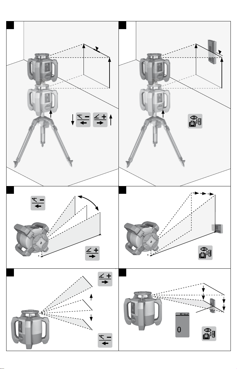
5.5 Manual horizontal alignment 8
The rotating laser is mounted on the PRA 90 automatic tripod. The PRA 30 laser receiver, the rotating laser and the PRA 90 automatic tripod are paired. The PRA 30 laser receiver and the control panel of the PRA 90 automatic tripod are facing each other and in direct line of sight.
1. Press the button on the rotating laser, on the PRA 30 laser receiver and on the PRA 90 automatic tripod. The devices are ready for use.
2. To shift the laser plane up, press the button on the PRA 30 laser receiver or the up arrow button on the PRA 90 automatic tripod.
3. To shift the laser plane down, press the button on the PRA 30 laser receiver or the down arrow button on the PRA 90 automatic tripod.
5.6 Automatic horizontal alignment 9
The rotating laser is mounted on the PRA 90 automatic tripod. The PRA 30 laser receiver, the rotating laser and the PRA 90 automatic tripod are paired. The PRA 30 laser receiver and the control panel of the PRA 90 automatic tripod are facing each other and in direct line of sight.
1. Press the button on the rotating laser, on the PRA 30 laser receiver and on the PRA 90 automatic tripod. The devices are ready for use.
2. Keep the marking notch on the PRA 30 laser receiver at the height that is to be set. The PRA 30 laser receiver should be held steady or secured in place.
3. Begin automatic alignment by double-clicking the button on the PRA 30 laser receiver. The PRA 90 automatic tripod moves up and down until the correct position is reached. An signal tone
is emitted repeatedly during this procedure. The rotating laser levels itself once the tripod has reached the correct position. Successful completion
is indicated by a continuous signal tone with a duration of 5 seconds. The symbol is no longer shown.
If automatic alignment cannot be completed successfully, short signal tones are emitted and the symbol disappears.
4. Check the height setting in the display. 5. Remove the PRA 30 laser receiver. 6. Stop automatic alignment before completion by double-clicking the button on the PRA 30 laser
receiver.
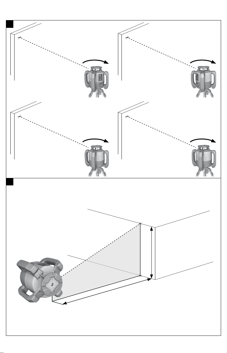
5.7 Manual vertical alignment 10
The rotating laser is placed or securely mounted in the vertical position (tripod, wall mount, facade or batter board adapter, or lying on the rear grips). A reference point (A) is marked below the laser head (e.g. a nail on a batter board or a spot of paint on the floor or ground). The PRA 30 laser receiver and the rotating laser are paired. The PRA 30 laser receiver and the receiving side of the rotating laser are facing each other and in direct line of sight. The best receiving side of the rotating laser is the side at which the battery is inserted.
1. Use the visual sighting method on the head to line up the vertical axis of the rotating laser. 2. Press the button on the rotating laser. The rotating laser levels itself and then projects a stationary downward-pointing laser beam.
3. Position the rotating laser so that the projected laser beam strikes reference point (A) exactly. Please note: The reference point is not a plumb point!
4. To shift the laser plane to the right or left, press the or button on the PRA 30 laser receiver. The rotating laser begins rotating after pressing one of the two direction arrow buttons.
*2134494* 2134494 English 11
5.8 Automatic vertical alignment 11
The rotating laser is placed or securely mounted in the vertical position (tripod, wall mount, facade or batter board adapter, or lying on the rear grips). A reference point (A) is marked below the laser head (e.g. a nail on a batter board or a spot of paint on the floor or ground). The PRA 30 laser receiver and the rotating laser are paired. The PRA 30 laser receiver and the receiving side of the rotating laser are facing each other and in direct line of sight. The best receiving side of the rotating laser is the side at which the battery is inserted.
1. Use the visual sighting method on the head to line up the vertical axis of the rotating laser. 2. Press the button on the rotating laser. The rotating laser levels itself and then projects a stationary downward-pointing laser beam.
3. Position the rotating laser so that the projected laser beam strikes reference point (A) exactly. Please note: The reference point is not a plumb point!
4. Keep the marking notch on the PRA 30 laser receiver on the plane that is to be set. The PRA 30 laser receiver should be held steady or secured in place.
5. Begin automatic alignment by double-clicking the button on the PRA 30 laser receiver. The head of the rotating laser pivots to the left and right until the desired position is reached. A signal
tone is emitted repeatedly during this procedure. The rotating laser levels itself once the position has been reached. Successful completion is indicated
by a continuous signal tone with a duration of 5 seconds. The symbol disappears. The rotating laser switches to surveillance mode. Surveillance when working in the vertical plane
page 6 If automatic alignment cannot be completed successfully, short signal tones are emitted and the
symbol disappears. 6. Do NOT remove the PRA 30 laser receiver from the target plane so long as surveillance mode is active. 7. Double-click the button on the PRA 30 laser receiver. During automatic alignment: Stops automatic alignment before completion. In surveillance mode: Ends surveillance mode.
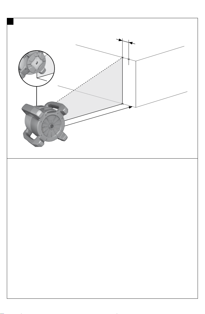
5.9 Setting the inclination using the PRA 79 slope adapter
Depending on the application, the PRA 79 slope adapter can be mounted on a tripod. The angle of inclination of the PRA 79 slope adapter is set to 0.
1. Mount the rotating laser on the PRA 79 slope adapter. Observe the operating instructions for the PRA 79 slope adapter. The control panel of the rotating laser should be facing you.
2. Position the rotating laser either at the upper edge or lower edge of the inclined plane. 3. Press the button on the rotating laser. The laser switches on, the beam begins to rotate and the auto leveling LED lights as soon as the
tool has leveled itself. 4. Press the button on the rotating laser. The inclined plane mode LED on the rotating laser then blinks.
5. Set the PRA 79 slope adapter to the desired angle of inclination.
When the angle of inclination is set manually, the rotating laser levels the laser plane once and then fixes it. Vibration, changes in temperature or other influences that may occur during the course of the day may affect the position of the laser plane.
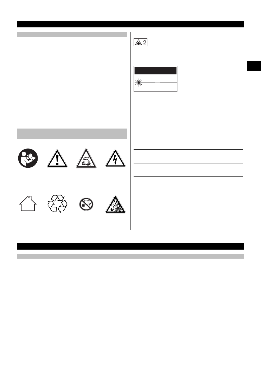
5.10 Setting the inclination manually 11
The rotating laser, depending on the application, is mounted or positioned securely. The PRA 30 laser receiver and the rotating laser are paired. The PRA 30 laser receiver and the receiving side of the rotating laser are facing each other and in direct line of sight. The best receiving side of the rotating laser is the side at which the battery is inserted.
1. Position the rotating laser either at the upper edge or lower edge of the inclined plane.
12 English 2134494
*2134494*
2. Position yourself behind the rotating laser with the control panel facing you. 3. Press the button on the rotating laser and the PRA 30 laser receiver. The laser switches on, the beam begins to rotate and the auto leveling LED lights as soon as the
tool has leveled itself. 4. Press the button on the rotating laser. The inclined plane mode LED on the rotating laser then blinks. The inclined plane mode symbol is shown on the PRA 30 laser receiver.
5. Use the target notch on the head of the tool to align the rotating laser parallel to the inclined plane. 6. To lower the laser plane ahead of the rotating laser, press the on the PRA 30 laser receiver repeatedly
until the desired value is shown in the display. 7. To raise the laser plane ahead of the rotating laser, press the on the PRA 30 laser receiver repeatedly
until the desired value is shown in the display. If no button is pressed within 3 seconds, the rotating laser levels itself to the previously set value. The
inclined plane mode LED lights.
A long press of the button causes the entered value to change rapidly.
When the angle of inclination is set manually, the rotating laser levels the laser plane once and then fixes it. Vibration, changes in temperature or other influences that may occur during the course of the day may affect the position of the laser plane.
5.11 Setting the inclination automatically 11
The rotating laser, depending on the application, is mounted or positioned securely. The PRA 30 laser receiver, depending on the application, is mounted on a receiver holder and telescopic staff. The PRA 30 laser receiver and the rotating laser are paired. The PRA 30 laser receiver and the receiving side of the rotating laser are facing each other and in direct line of sight. The best receiving side of the rotating laser is the side at which the battery is inserted.
1. Position the rotating laser either at the upper edge or lower edge of the inclined plane. 2. Hold the PRA 30 laser receiver right beside the rotating laser and adjust the height the PRA 30 laser
receiver so that the marking notch is at the height of the laser plane. Fix the height of the telescopic staff. 3. Position the telescopic staff with the PRA 30 laser receiver at the other edge of the inclined plane. 4. Press the button on the rotating laser and the PRA 30 laser receiver. The laser switches on, the beam begins to rotate and the auto leveling LED lights as soon as the
tool has leveled itself. 5. Press the button on the rotating laser. The inclined plane mode LED on the rotating laser then blinks. The inclined plane mode symbol is shown on the PRA 30 laser receiver.
6. Begin automatic alignment by double-clicking the button on the PRA 30 laser receiver. The rotating laser inclines the laser plane automatically until the mark at the PRA 30 laser receiver is
reached. An signal tone is emitted repeatedly during this procedure. The rotating laser levels itself once the position has been reached. Successful completion is indicated
by a continuous signal tone with a duration of 5 seconds. The symbol disappears. If automatic alignment cannot be completed successfully, short signal tones are emitted and the
indication in the display disappears. 7. Read the inclination from the PRA 30 laser receiver within 5 seconds. 8. Stop automatic inclination before completion by double-clicking the button on the PRA 30 laser
receiver.
If the rotating laser begins the automatic search in the wrong direction, press the button to change the search direction.
*2134494* 2134494 English 13
5.12 Alignment using electronic inclination alignment (e-targeting)
Electronic inclination alignment optimizes manual alignment of the rotating laser. The electronic method is more accurate.
The rotating laser, depending on the application, is mounted or positioned securely. The PRA 30 laser receiver and the rotating laser are paired. The PRA 30 laser receiver and the receiving side of the rotating laser are facing each other and in direct line of sight. The best receiving side of the rotating laser is the side at which the battery is inserted.
1. Set the inclination of the laser plane automatically. page 12 2. Press the button on the rotating laser. If both arrows blink, the PRA 30 laser receiver is receiving no signal from the rotating laser. Use the marking notch on the PRA 30 laser receiver to bring the rotating laser into alignment.
If the left arrow lights , turn the rotating laser clockwise. If the left right arrow lights , turn the rotating laser counterclockwise. If both arrows light constantly for 10 seconds, alignment of the PRA 30 laser receiver is correct and
the procedure ends. 3. Secure the rotating laser on the tripod in this position. 4. Stop electronic inclination alignment before completion by double-clicking the button on the rotating
laser.
5.13 Deactivating the shock warning function
1. Switch the laser on. page 9 2. Press the button. The shock warning deactivation LED lights constantly, indicating that the function has been
deactivated.
To return to standard operating mode, switch the laser tool off and then switch it back on again.
5.14 Activating / deactivating sleep mode
Sleep mode may be activated on the rotating laser during breaks between work or during other activities. All settings concerning the laser plane or inclination are retained while in this status. Sleep mode saves power and extends battery life. Please also refer to PRA 30 laser receiver menu options for information about settings.
1. Switch the laser receiver off. 2. Press the button for 2 seconds. 3. Press the button twice and go to the sleep mode menu option. 4. Set the mode by pressing the button. The status set is highlighted in black. 5. After ending sleep mode, check the laser settings in order to ensure continued working accuracy.
Sleep mode remains active for a maximum of 4 hours.
5.15 Checking the main and transverse horizontal axes 14
1. Set up the tripod approx. 20 m (66 ft) from a wall and adjust the tripod head horizontally with a spirit level. 2. Mount the tool on the tripod and use the visual sighting method (front and rear sights) to aim the tool at
the wall. 3. Fig. a: Use the receiver to cat
Table of Contents
- Information about the operating instructions
- About these operating instructions
- Explanation of symbols used
- Warnings
- Symbols in the documentation
- Symbols in the illustrations
- Product-dependent symbols
- Symbols on the product
- On the product
- Product information
- Declaration of conformity
- Safety
- Basic information concerning safety
- General safety measures
- Proper preparation of the working area
- Electromagnetic compatibility
- Laser classification for Class 2 laser products
- Careful use of battery-powered tools
- Description
- Product overview
- PR 30-HVS rotating laser 1
- PR 30-HVS control panel 2
- PRA 30 laser receiver and control panel 3
- PRA 30 laser receiver display 4
- Intended use
- Features
- LED indicators
- Li-ion battery charge state display
- Items supplied
- Product overview
- Technical data
- Technical data, rotating laser
- Technical data, laser receiver
- Operating the rotating laser
- Preparations at the workplace
- Handling the laser and battery correctly 5
- Inserting / removing the battery 6
- Switching the laser on and working in the horizontal plane 7
- Manual horizontal alignment 8
- Automatic horizontal alignment 9
- Manual vertical alignment 10
- Automatic vertical alignment 11
- Setting the inclination using the PRA 79 slope adapter
- Setting the inclination manually 11
- Setting the inclination automatically 11
- Alignment using electronic inclination alignment (e-targeting)
- Deactivating the shock warning function
- Activating / deactivating sleep mode
- Checking the main and transverse horizontal axes 14
- Checking the vertical axis 15
- Operating the laser receiver
- Inserting the batteries in the laser receiver 12
- Pairing the rotating laser and the PRA 30 laser receiver
- Pairing the PRA 90 tripod and the PRA 30 laser receiver
- Using the laser receiver to detect the laser beam
- Setting the units to be used
- Changing the units used by the laser receiver
- Adjusting the volume level on the laser receiver
- Adjusting the signal tone on the laser receiver
- PRA 30 Menu options
- PRA 83 laser receiver with holder 13
- Care and maintenance
- Care and maintenance
- Hilti Measuring Systems Service
- Checking accuracy
- Transport and storage
- Transport and storage of cordless tools and batteries
- Troubleshooting
- RoHS (Restriction of Hazardous Substances)
- Disposal
- Manufacturer’s warranty
- References
- Read User Manual Online (PDF format)
- Download This Manual (PDF format)


Original operating instructions
Information about the operating instructions
About these operating instructions
- Read these operating instructions before the product is used or operated for the first time. This is a prerequisite for safe, trouble-free handling and use of the product.
- Observe the safety instructions and warnings in these operating instructions and on the product.
- Always keep the operating instructions with the product and make sure that the product is accompanied by these operating instructions only, when the product is given to other persons.
Explanation of symbols used
Warnings
Warnings alert persons to hazards that occur when handling or using the
product. The following signal words are used
DANGER !
- Draws attention to imminent danger that will lead to serious personal injury or fatality.
WARNING !
- Draws attention to a potential threat of danger that can lead to serious injury or fatality.
CAUTION !
- Draws attention to a potentially dangerous situation that could lead to personal injury or damage to the equipment or other property.
Symbols in the documentation
The following symbols are used in this document:
| Read the operating instructions before use.
—|—
| Instructions for use and other useful information
| Dealing with recyclable materials
| Do not dispose of electric equipment and batteries as household waste
Symbols in the illustrations
The following symbols are used in illustrations:
| These numbers refer to the corresponding illustrations found at the
beginning of these operating instructions
—|—
| The numbering reflects the sequence of operations shown in the illustrations
and may deviate from the steps described in the text
| Item reference numbers are used in the overview illustrations and refer
to the numbers used in the product overview section
| This symbol is intended to draw special attention to certain points when
handling the product.
Product-dependent symbols
Symbols on the product
The following symbols can be used on the product:
| The product supports wireless data transmission compatible with iOS and
Android platforms.
—|—
| Hilti Li-ion battery type series used. Observe the information given in
the section headed Intended use.
| Li-ion battery
| Never use the battery as a striking tool.
| Do not drop the battery. Never use a battery that has suffered an impact or
is damaged in any other way.
On the product
Laser information
| Laser class 2 based on standard IEC60825-1 / EN60825-1:2007 and compliant
with CFR 21 § 1040 (Laser Notice 50). Do not look straight into the laser
beam.
—|—
Product information
products are designed for professional users and only trained, authorized
personnel are permitted to operate, service and maintain the products. This
personnel must be specifically informed about the possible hazards. The
product and its ancillary equipment can present hazards if used incorrectly by
untrained personnel or if used not in accordance with the intended use. The
type designation and serial number are printed on the rating plate.
- Write down the serial number in the table below. You will be required to state the product details when contacting Hilti Service or your local Hilti organization to inquire about the product.
Product information
Rotating laser|
PR 30-HVS A12
—|—
Generation|
02
Serial no.|
Product information
Rotating laser|
PRA 30
—|—
Generation|
03
Serial no.|
Declaration of conformity
We declare, on our sole responsibility, that the product described here
complies with the applicable directives
and standards. A copy of the declaration of conformity can be found at the end
of this documentation.
The technical documentation is filed here:
Hilti Entwicklungsgesellschaft mbH | Tool Certification | Hiltistrasse 6
| D-86916 Kaufering, Germany
Safety
Basic information concerning safety
Read all safety instructions and other instructions. Failure to observe
the safety instructions and other instructions may result in electric shock,
fire and/or serious injury.
Retain all safety precautions and instructions for future reference. The
term “electric tool” used in the safety instructions refers to your mains-
operated (corded) electric tool or battery-operated (cordless) electric tool.
General safety measures
- Stay alert, watch what you are doing and use common sense when operating a power tool. Do not use a power tool while you are tired or under the influence of drugs, alcohol or medication. A moment of inattention while operating the power tool can result in serious personal injury.
- Do not render safety devices ineffective and do not remove information and warning notices.
- Keep children well away from laser devices.
- Laser radiation in excess of Class 2 may be emitted if the device is opened without following the correct procedures. Have the device repaired only by Hilti Service.
- Project laser beams well above or well below eye height.
- Take the influences of the surrounding area into account. Do not use the device where there is a risk of fire or explosion.
- Statement in accordance with FCC §15.21: Changes or modifications not expressly approved by Hilti can restrict the user’s authorization to operate the equipment.
- You must check the accuracy of the device after it has been dropped or subjected to other mechanical stresses.
- When the device is brought into a warm environment from very cold conditions, or vice-versa, allow it to become acclimatized before use.
- When using adapters or accessories, make sure that the equipment is securely mounted.
- Keep the laser aperture clean to avoid measurement errors.
- The device is designed for the tough conditions of jobsite use, but as with other optical and electronic instruments (e.g. binoculars, spectacles, cameras) it must be handled with care.
- The device is protected to prevent the ingress of moisture, but you must always wipe it dry before stowing it in the transport container.
- Check the device before using it for important measuring work.
- Repeatedly check accuracy while using the device.
- Make sure that the workplace is well lit.
- Do not expose the laser to rain or wet conditions.
- Do not touch the contacts.
- Maintain the device carefully. Check that moving parts are in full working order and do not jam and make sure there are no parts that are broken or damaged in such a way as to impair operation of the device. If it damaged, have the device repaired before use. Many accidents are caused by poorly maintained equipment
Proper preparation of the working area
- Secure the area in which you will be taking measurements. Make sure that the laser beam is not directed toward other persons or toward yourself while setting up the laser tool.
- Avoid unfavorable body positions when working from ladders. Make sure you work from a safe stance and stay in balance at all times.
- Readings taken in the vicinity of reflective objects or surfaces, through panes of glass or similar materials may produce incorrect results.
- Ensure that the tool is set up on a stable, level surface (not subject to vibration).
- Use the tool only within its specified limits.
- Use the tool and its accessories etc. in accordance with these instructions and in the manner intended for the particular type of tool. Take the working conditions and the work to be performed into account. Use of tools for applications different from those intended could result in a hazardous situation.
- Use of the telescopic staff in the vicinity of overhead high voltage cables is not permissible.
Electromagnetic compatibility
Although the tool complies with the strict requirements of the applicable
directives, Hilti cannot exclude the following possibilities:
-
The tool may be negatively affected by powerful electromagnetic radiation, possibly leading to incorrect operation.
In these cases, or if you are otherwise unsure, confirmatory measurements
should be made by other means. -
The tool can cause interference to other devices (e.g. aircraft navigation equipment).
Laser classification for Class 2 laser products
The tool complies with laser Class 2 as per IEC60825-1:2007 / EN60825-1:2007.
This tool may be used without need for further protective measures.
CAUTION
Risk of injury! Do not direct the laser beam toward persons.
- Never look directly into the source of the laser beam. In the event of direct eye contact, close your eyes and move your head out of the path of the laser beam.
- Do not expose batteries to high temperatures, the direct heat of the sun, and keep them away from fire. There is a risk of explosion.
- Do not disassemble, squash or incinerate batteries and do not subject them to temperatures over 80°C (176°F). This presents a risk of fire, explosion or injury through contact with caustic substances.
- Do not subject the battery to hard mechanical impacts and do not throw the battery.
- Batteries must be kept out of reach of children.
- Avoid ingress of moisture. Ingress of moisture may cause a short circuit, resulting in burning injuries or fire.
- Under abusive conditions, liquid may leak from the battery. Avoid contact with the liquid. If contact accidentally occurs, flush with water. If the liquid contacts the eyes, also seek medical attention. Liquid leaking from the battery may cause irritation or burns.
- Use only batteries of the type approved for use with the applicable tool. Use of other batteries or use of the batteries for purposes for which they are not intended presents a risk of fire and explosion.
- Store the battery in a cool and dry place. Never store the battery where it is exposed to direct sunlight or sources of heat, e.g. on heaters / radiators or behind glass.
- When not in use, keep the battery and the charger away from paper clips, coins, keys, nails, screws or other small metal objects that could cause a short circuit at the battery terminals or the charging contacts. Short-circuiting the contacts on a battery or charger may cause burning injuries or start a fire.
- Do not charge or continue to use damaged batteries (e.g. batteries with cracks, broken parts, bent or pushed-in and/or pulled-out contacts).
- Recharge only with the charger specified by the manufacturer. A charger that is suitable for a certain type of battery may present a risk of fire when used with other types of battery.
- Observe the special guidelines applicable to the transport, storage and use of Li-ion batteries.
- The battery must be insulated or removed from the tool before the tool is shipped or sent by mail. Leaking batteries may damage the tool.
- If the battery gets noticeably hot when not in use, this may indicate that the battery or the tool / battery system is faulty. In this case, place the tool in a non-flammable location, well away from flammable materials, where it can be kept under observation and allowed to cool down.
Description
Product overview
PR 30-HVS rotating laser 1


- Laser beam (plane of rotation)
- Rotary head
- Sight
- Grip
- Battery release button
- Li-ion battery
- Battery state-of-charge display
- Control panel
- Base plate with 5/8″ thread
PR 30-HVS control panel 2
- Inclined plane mode button and LED
- Shock warning function button and LED
- LED arrow for electronic inclination alignment
- Electronic inclination alignment button (only in combination with inclined plane mode)
- Auto-leveling LED
- On/off button
- Surveillance mode LED (only with automatic vertical alignment)
- Battery charge status LED
PRA 30 laser receiver and control panel 3
- Volume button
- Negative inclination to the left or downward with PRA 90
- Automatic alignment / surveillance mode in the vertical plane (double-click)
- Units key
- Positive inclination to the right or upward with PRA 90
- On/off button
- Display
- Marking notch
- Detection area
PRA 30 laser receiver display 4
- Indicator showing distance from laser plane
- Volume indicator
- Units key
- Detection area
- Marking notch
Intended use
The product described is a rotating laser with a visible rotating laser beam.
It can be operated by one person. The tool is designed to be used to
determine, transfer and check levels, verticals, slopes and right angles.
Examples of its uses are: transferring datum lines and height marks,
determining right angles for walls, vertical alignment on reference points and
setting out slopes.
- Use only the Hilti B12/2.6 and respectively the B 1230 Li ion battery for this product.
- Use only the Hilti C 4⁄1250 charger for this product.
Features
The rotating laser can be used vertically, horizontally and for inclined
planes.
The tool is equipped with the following operating status indicators: auto-
leveling LED, inclined plane mode LED, surveillance mode LED and shock warning
LED.
Auto-leveling
Auto-leveling takes place after the tool is switched on. LEDs indicate the
current operating status. Auto leveling is active within the ±5° range
relative to the horizontal plane and can be deactivated by pressing the
button. The tool can be set up directly on the ground or floor, on a tripod,
or with the aid of suitable mounting brackets.
Automatic alignment
Automatic alignment allows a single person to bring the laser plane into
alignment with the laser receiver. The rotating laser tool detects the
applicable direction of alignment as follows:
- Horizontal in conjunction with the PRA 90 automatic tripod and PRA 30 laser receiver.
- Inclination in conjunction with the PRA 30 laser receiver, and (optional) with the PRA 79 slope adapter.
- Vertical in conjunction with the PRA 30 laser receiver.
Inclination angle
The inclination can be set by the following means:
- Manual entry of the values at the PRA 30 laser receiver
- Automatic alignment of the rotating laser with the PRA 30 laser receiver
- Presetting an inclination through use of the PRA 79 slope adapter
The angle of inclination can be read from the laser receiver.
Surveillance when working in the vertical plane
The rotating laser monitors alignment of the laser plane in combination with
the PRA 30 laser receiver. In the event of deviations in alignment, laser
rotation stops for 40 seconds. During this time the tool corrects all errors
caused by temperature fluctuations, wind or other influences. Laser rotation
restarts after this automatic correction. If necessary, the surveillance
function can be deactivated.
Automatic switch-off
The tool switches off automatically if it is unable to level itself because
the laser:
• Is inclined at more than 5° relative to the horizontal plane (except in
inclined plane mode).
• Is blocked mechanically.
• Has been knocked off level by an impact or vibration.
When the tool has switched itself off, rotation stops and all LEDs flash.
Shock warning function
If the laser is knocked off level during operation, the built-in shock warning
function switches the tool to warning mode. The shock warning function does
not go active until two minutes after completion of auto leveling. If a button
on the control panel is pressed within this two-minute period it will take a
further two
minutes for the shock warning function to go active. If the laser is in
warning mode:
- All LEDs flash.
- The laser stops rotating.
- The laser beam switches off.
The shock warning function can be switched off by pressing the button if
the ground or floor is not free from vibration or when you are working in
inclined plane mode.
- Deactivate the shock warning function. → page 32
Laser receiver / remote control unit
Hilti laser receivers digitally indicate the distance between the marking
notch on the laser receiver and the position at which the laser beam (laser
plane) strikes the detection area on the receiver. The laser beam can also be
received over long distances. The PRA 30 can be used as a laser receiver and
also as a remote
control unit for the rotating laser. The system of units and the unit of
measurement can be set as desired.
- Set the units that are to be used. → page 34
- Change the units used by the laser receiver. → page 34
Pairing accessories and device
Pairing is the act of enabling accessories and devices to communicate with
each other by wireless. The rotating laser and the laser receiver are already
paired when supplied. This helps ensure trouble-free operation within the
vicinity of other wireless devices. Additional laser receivers or PRA 90
automatic tripods cannot be used without first being paired.
- Pair the rotating laser and the laser receiver. → page 33
- Pair the tripod and laser receiver. → page 33
LED indicators
The rotating laser is equipped with an LED display
| Status | Meaning |
|---|---|
| All LEDs blink | The tool has been bumped, knocked off level or is subject to |
some other error.
The auto-leveling LED blinks green.| The tool is in the leveling phase.
The auto-leveling LED lights green constantly.| The tool has leveled itself /
is operating normally.
The shock warning LED lights orange constantly.| Shock warning mode is
deactivated.
The inclination LED blinks orange.| Alignment in the sloping plane.
The inclination LED lights orange constantly| Inclined plane mode is active.
The surveillance LED blinks orange| . The tool is aligning the laser plane
with the reference point (PRA 30).
The surveillance mode LED lights orange constantly.| The tool is in
surveillance mode. Alignment with the reference point (PRA 30) is correct.
The LED arrows blink orange.| The tool is in electronic inclination alignment
mode, the PRA 30 is receiving no laser beam.
The LED arrows light orange constantly.| The tool is correctly aligned with
the PRA 30.
The left LED arrow lights orange| Rotate the tool clockwise.
The right LED arrow lights orange.| Rotate the tool counterclockwise.
Li-ion battery charge state display
The Li-ion battery features a state of charge display.
| Status | Meaning |
|---|---|
| 4 LEDs light | Charge status: 75 % to 100 % |
| 3 LEDs light | Charge status: 50 % to 75 % |
| 2 LEDs light | Charge status: 25 % to 50 % |
| 1 LEDs light | Charge status: 10 % to 25 % |
| 1 LEDs light | Charge status: < 10 % |
When the tool is in operation, the battery charge status is indicated in the
display on the tool. When not in operation, battery charge state can be
indicated by lightly pressing the release button. During charging, charge
state is indicated by the LEDs on the battery (please refer to the operating
instructions for the charger).
Items supplied
PR 30-HVS A12 rotating laser, PRA 30 (03) laser receiver / remote control
unit, 2 batteries (AA cells), PRA 83 laser receiver holder, operating
instructions.
Other system products approved for use with this product can be found at your
local Hilti Store or at: www.hilti.group | USA:
www.hilti.com
Technical data
Technical data, rotating laser
| PR 30-HVS A12
—|—
Rated voltage| 10.8 V
Rated current| 120 mA
Maximum relative humidity| 80 %
Maximum site elevation above datum| 2,000 m
Receiving range (diameter) PRA 30 (03)| 2 m … 500 m
Communication range (PRA 30)| 150 m
Accuracy at 10 m (under standard ambient conditions in accordance with
MILSTD810G)| ±0.5 mm
Laser class| Visible, Laser Class 2, 620-690 nm/Po<4.85 mW ≥ 300 ⁄min;
EN 60825-1:2007; IEC 60825-1:2007><4.85 mW>300 ⁄min; EN 60825-1:2007; IEC
60825-1:2007
Self-leveling range| ±5°
Maximum site elevation above datum| 2,000 m
Maximum relative humidity| 80 %
Operating temperature| −20 ℃ … 50 ℃
Storage temperature| −25 ℃ … 60 ℃
Weight (including B12/2.6 and respectively B 1230 battery)| 2.5 kg
Drop test height (under standard ambient conditions in accordance with
MILSTD810G)| 1.5 m
Protection class in accordance with IEC 60529 (except battery and battery
compartment)| IP66
Plumb beam| Constant beam, perpendicular to the plane of rotation
Maximum emitted transmission power| 7.8 dBm
Frequency| 2,400 MHz … 2,483.5 MHz
Technical data, laser receiver
| Rated voltage | 3 V |
|---|---|
| Rated current | 150 mA |
| Maximum relative humidity | 80 % |
| Maximum site elevation above datum | 2,000 m |
| Indicator range, distance from zero | ±52 mm |
| Laser plane display range | ±0.5 mm |
| Length of the detection area | ≤ 120 mm |
| Center indication from top edge of casing | 75 mm |
| Time without detection before automatic power off | 15 min |
| Range of remote control unit (diameter) for the PR 30-HVS | 2 m … 150 m |
Drop test height in the PRA 30 laser receiver holder (under standard
ambient conditions in accordance with MILSTD810G)| 2 m
Operating temperature| −20 ℃ … 50 ℃
Storage temperature| −25 ℃ … 60 ℃
Weight (including batteries)| 0.25 kg
Protection class in accordance with IEC 60529 (except battery
compartment)| IP66
Maximum emitted transmission power| −0.2 dBm
Frequency| 2,400 MHz … 2,483.5 MHz
Operating the rotating laser
Preparations at the workplace
WARNING
Risk of injury by inadvertent starting!
- Before inserting the battery, make sure that the product is switched off.
- Remove the battery before making any adjustments to the power tool or before changing accessories.
Observe the safety instructions and warnings in this documentation and on the
product.
Handling the laser and battery correctly 5
The B12 battery has no protection class. Do not expose the battery to rain or
wet conditions. In accordance with the Hilti instructions, the battery may be
used only with the associated product and must be inserted in the battery
compartment for this purpose.
- Fig. 1: Working in horizontal mode.
- Fig. 2: In inclined plane mode, the laser should be lifted at the control panel side.
- Fig. 3: Laying down or transporting in an inclined position. Working in the vertical plane.
▶ Hold the laser so that the battery compartment does NOT face upwards, so
that no moisture can enter.
Inserting / removing the battery 6
CAUTION
Electrical hazard. Dirty contacts may cause a short circuit.
- Check that the contacts on the battery and on the tool are free from foreign objects before inserting the battery.
CAUTION
Risk of injury. If the battery is not fitted correctly it may drop out and
fall.
- Check that the battery is securely seated in the tool so that it cannot drop out and fall, thereby presenting a hazard to other persons.
-
Push the battery in until it engages securely.
▶ The laser is ready to switch on. -
Press the release button and hold it in this position.
-
Pull the battery out.
Switching the laser on and working in the horizontal plane 7
Check the accuracy of the laser tool before using it for important measuring
tasks, especially if it has been dropped or subjected to unusual influences or
impacts etc.
- Mount the laser on a suitable holder or bracket.
- Press the button.
▶ The auto-leveling LED flashes green.
▶ As soon as the tool has leveled itself, the laser beam switches on and
begins to rotate and the “auto leveling” LED shows steadily.
A wall bracket or tripod may be used as mounting devices. The angle of
inclination of the surface on which it stands should not exceed ± 5°.
Manual horizontal alignment 8
The rotating laser is mounted on the PRA 90 automatic tripod.
The PRA 30 laser receiver, the rotating laser and the PRA 90 automatic tripod
are paired.
The PRA 30 laser receiver and the control panel of the PRA 90 automatic tripod
are facing each other and in direct line of sight.
-
Press the button on the rotating laser, on the PRA 30 laser receiver and on the PRA 90 automatic tripod.
▶ The devices are ready for use. -
To shift the laser plane up, press the button on the PRA 30 laser receiver or the “up” arrow button on the PRA 90 automatic tripod.
-
To shift the laser plane down, press the button on the PRA 30 laser receiver or the “down” arrow button on the PRA 90 automatic tripod.
Automatic horizontal alignment 9
The rotating laser is mounted on the PRA 90 automatic tripod.
The PRA 30 laser receiver, the rotating laser and the PRA 90 automatic tripod
are paired.
The PRA 30 laser receiver and the control panel of the PRA 90 automatic tripod
are facing each other and in direct line of sight.
-
Press the button on the rotating laser, on the PRA 30 laser receiver and on the PRA 90 automatic tripod.
▶ The devices are ready for use. -
Keep the marking notch on the PRA 30 laser receiver at the height that is to be set. The PRA 30 laser receiver should be held steady or secured in place.
-
Begin automatic alignment by double-clicking the button on the PRA 30 laser receiver.
▶ The PRA 90 automatic tripod moves up and down until the correct position is
reached. An signal tone is emitted repeatedly during this procedure.
▶ The rotating laser levels itself once the tripod has reached the correct
position. Successful completion is indicated by a continuous signal tone with
a duration of 5 seconds. The symbol is no longer shown.
▶ If automatic alignment cannot be completed successfully, short signal tones
are emitted and the symbol disappears. -
Check the height setting in the display.
-
Remove the PRA 30 laser receiver.
-
Stop automatic alignment before completion by double-clicking the button on the PRA 30 laser receiver.
Manual vertical alignment 10
The rotating laser is placed or securely mounted in the vertical position
(tripod, wall mount, facade or batter board adapter, or lying on the rear
grips). A reference point (A) is marked below the laser head (e.g. a nail on a
batter board or a spot of paint on the floor or ground).
The PRA 30 laser receiver and the rotating laser are paired.
The PRA 30 laser receiver and the receiving side of the rotating laser are
facing each other and in direct line of sight. The best receiving side of the
rotating laser is the side at which the battery is inserted.
-
Use the visual sighting method on the head to line up the vertical axis of the rotating laser.
-
Press the button on the rotating laser.
▶ The rotating laser levels itself and then projects a stationary downward-
pointing laser beam. -
Position the rotating laser so that the projected laser beam strikes reference point (A) exactly. Please note: The reference point is not a plumb point!
-
To shift the laser plane to the right or left, press the or button on the PRA 30 laser receiver.
▶ The rotating laser begins rotating after pressing one of the two direction
arrow buttons.
Automatic vertical alignment 11
The rotating laser is placed or securely mounted in the vertical position
(tripod, wall mount, facade or batter board adapter, or lying on the rear
grips). A reference point (A) is marked below the laser head (e.g. a nail on a
batter board or a spot of paint on the floor or ground).
The PRA 30 laser receiver and the rotating laser are paired.
The PRA 30 laser receiver and the receiving side of the rotating laser are
facing each other and in direct line of sight. The best receiving side of the
rotating laser is the side at which the battery is inserted.
-
Use the visual sighting method on the head to line up the vertical axis of the rotating laser.
-
Press the button on the rotating laser.
▶ The rotating laser levels itself and then projects a stationary downward-
pointing laser beam. -
Position the rotating laser so that the projected laser beam strikes reference point (A) exactly. Please note: The reference point is not a plumb point!
-
Keep the marking notch on the PRA 30 laser receiver on the plane that is to be set. The PRA 30 laser receiver should be held steady or secured in place.
-
Begin automatic alignment by double-clicking the button on the PRA 30 laser receiver.
▶ The head of the rotating laser pivots to the left and right until the
desired position is reached. A signal tone is emitted repeatedly during this
procedure.
▶ The rotating laser levels itself once the position has been reached.
Successful completion is indicated by a continuous signal tone with a duration
of 5 seconds. The symbol disappears.
▶ The rotating laser switches to surveillance mode. Surveillance when working
in the vertical plane → page 25
▶ If automatic alignment cannot be completed successfully, short signal tones
are emitted and the symbol disappears. -
Do NOT remove the PRA 30 laser receiver from the target plane so long as surveillance mode is active.
-
Double-click the button on the PRA 30 laser receiver.
▶ During automatic alignment: Stops automatic alignment before completion.
▶ In surveillance mode: Ends surveillance mode.
Setting the inclination using the PRA 79 slope adapter
Depending on the application, the PRA 79 slope adapter can be mounted on a
tripod. The angle of inclination of the PRA 79 slope adapter is set to 0°
-
Mount the rotating laser on the PRA 79 slope adapter. Observe the operating instructions for the PRA 79 slope adapter. The control panel of the rotating laser should be facing you.
-
Position the rotating laser either at the upper edge or lower edge of the inclined plane.
-
Press the button on the rotating laser.
-
▶ The laser switches on, the beam begins to rotate and the “auto leveling” LED lights as soon as the tool has leveled itself.
-
Press the button on the rotating laser.
▶ The inclined plane mode LED on the rotating laser then blinks. -
Set the PRA 79 slope adapter to the desired angle of inclination.
When the angle of inclination is set manually, the rotating laser levels the
laser plane once and then fixes it. Vibration, changes in temperature or other
influences that may occur during the course of the day may affect the position
of the laser plane
Setting the inclination manually 11
The rotating laser, depending on the application, is mounted or positioned
securely.
The PRA 30 laser receiver and the rotating laser are paired.
The PRA 30 laser receiver and the receiving side of the rotating laser are
facing each other and in direct line of sight. The best receiving side of the
rotating laser is the side at which the battery is inserted.
-
Position the rotating laser either at the upper edge or lower edge of the inclined plane
-
Position yourself behind the rotating laser with the control panel facing you.
-
Press the button on the rotating laser and the PRA 30 laser receiver.
▶ The laser switches on, the beam begins to rotate and the “auto leveling” LED
lights as soon as the tool has leveled itself. -
Press the button on the rotating laser.
▶ The inclined plane mode LED on the rotating laser then blinks.
▶ The inclined plane mode symbol is shown on the PRA 30 laser receiver. -
Use the target notch on the head of the tool to align the rotating laser parallel to the inclined plane.
-
To lower the laser plane ahead of the rotating laser, press the on the PRA 30 laser receiver repeatedly until the desired value is shown in the display.
-
To raise the laser plane ahead of the rotating laser, press the on the PRA 30 laser receiver repeatedly until the desired value is shown in the display.
▶ If no button is pressed within 3 seconds, the rotating laser levels itself
to the previously set value. The inclined plane mode LED lights.
A long press of the button causes the entered value to change rapidly.
When the angle of inclination is set manually, the rotating laser levels the
laser plane once and then fixes it. Vibration, changes in temperature or other
influences that may occur during the course of the day may affect the position
of the laser plane.
Setting the inclination automatically 11
The rotating laser, depending on the application, is mounted or positioned
securely.
The PRA 30 laser receiver, depending on the application, is mounted on a
receiver holder and telescopic staff.
The PRA 30 laser receiver and the rotating laser are paired.
The PRA 30 laser receiver and the receiving side of the rotating laser are
facing each other and in direct line of sight. The best receiving side of the
rotating laser is the side at which the battery is inserted.
-
Position the rotating laser either at the upper edge or lower edge of the inclined plane.
-
Hold the PRA 30 laser receiver right beside the rotating laser and adjust the height the PRA 30 laser receiver so that the marking notch is at the height of the laser plane. Fix the height of the telescopic staff.
-
Position the telescopic staff with the PRA 30 laser receiver at the other edge of the inclined plane.
-
Press the button on the rotating laser and the PRA 30 laser receiver.
▶ The laser switches on, the beam begins to rotate and the “auto leveling” LED
lights as soon as the tool has leveled itself. -
Press the button on the rotating laser.
▶ The inclined plane mode LED on the rotating laser then blinks.
▶ The inclined plane mode symbol is shown on the PRA 30 laser receiver. -
Begin automatic alignment by double-clicking the button on the PRA 30 laser receiver.
▶ The rotating laser inclines the laser plane automatically until the mark at
the PRA 30 laser receiver is reached. An signal tone is emitted repeatedly
during this procedure.
▶ The rotating laser levels itself once the position has been reached.
Successful completion is indicated by a continuous signal tone with a duration
of 5 seconds. The symbol disappears.
▶ If automatic alignment cannot be completed successfully, short signal tones
are emitted and the indication in the display disappears.
7. Read the inclination from the PRA 30 laser receiver within 5 seconds.
8. Stop automatic inclination before completion by double-clicking the button
on the PRA 30 laser receiver
If the rotating laser begins the automatic search in the wrong direction,
press the button to change the search direction.
Alignment using electronic inclination alignment (e-targeting)
Electronic inclination alignment optimizes manual alignment of the rotating
laser. The electronic method is more accurate.
The rotating laser, depending on the application, is mounted or positioned
securely.
The PRA 30 laser receiver and the rotating laser are paired.
The PRA 30 laser receiver and the receiving side of the rotating laser are
facing each other and in direct line of sight. The best receiving side of the
rotating laser is the side at which the battery is inserted.
-
Set the inclination of the laser plane automatically. → page 31
-
Press the button on the rotating laser.
▶ If both arrows blink, the PRA 30 laser receiver is receiving no signal from
the rotating laser.
▶ Use the marking notch on the PRA 30 laser receiver to bring the rotating
laser into alignment.
▶ If the left arrow lights , turn the rotating laser clockwise.
▶ If the left right arrow lights , turn the rotating laser counterclockwise.
▶ If both arrows light constantly for 10 seconds, alignment of the PRA 30
laser receiver is correct and the procedure ends. -
Secure the rotating laser on the tripod in this position.
-
Stop electronic inclination alignment before completion by double-clicking the button on the rotating laser
Deactivating the shock warning function
- Switch the laser on. → page 28
- Press the button.
▶ The shock warning deactivation LED lights constantly, indicating that the
function has been deactivated.
To return to standard operating mode, switch the laser tool off and then
switch it back on again.
Activating / deactivating sleep mode
Sleep mode may be activated on the rotating laser during breaks between work
or during other activities. All settings concerning the laser plane or
inclination are retained while in this status. Sleep mode saves power and
extends battery life.
Please also refer to “PRA 30 laser receiver menu options” for information
about settings.
- Switch the laser receiver off.
- Press the button for 2 seconds.
- Press the button twice and go to the sleep mode menu option.
- Set the mode by pressing the button. The status set is highlighted in black.
- After ending sleep mode, check the laser settings in order to ensure continued working accuracy.
Sleep mode remains active for a maximum of 4 hours.
Checking the main and transverse horizontal axes 14
- Set up the tripod approx. 20 m (66 ft) from a wall and adjust the tripod head horizontally with a spirit level.
- Mount the tool on the tripod and use the visual sighting method (front and rear sights) to aim the tool at the wall.
- Fig. a: Use the receiver to catch the laser beam and mark a point (point 1) on the wall.
- Pivot the tool clockwise through 90° about its own axis. In doing so, ensure that the height of the tool does not change.
- Fig. b: Use the laser receiver to catch the laser beam and mark a second point (point 2) on the wall.
- Fig. c and d: Repeat the two previous steps twice and use the laser receiver to catch the beam and mark points 3 and 4 on the wall.
If the procedure has been carried out accurately, the vertical distance
between the two marked points 1 and 3 (main axis) or points 2 and 4
(transverse axis) should each be < 2 mm (at 20 m) (0.12″ at 66 ft). If the
deviation is greater than this, please return the tool to Hilti Service for
calibration.
Checking the vertical axis 15
- Place the tool in the vertical position on the floor or ground, which should be as flat as possible, approx. 20 m (66 ft) from a wall.
- Align the grips parallel to the wall.
- Switch the tool on and mark the reference point (R) on the ground or floor.
- With the aid of the receiver, mark point (A) low on the wall.
- With the aid of the receiver, mark point (B) at a height of approx. 10 m (33 ft).
- Pivot the tool through 180° and realign it with the reference point (R) on the ground or floor and with point (A) at the base of the wall.
- With the aid of the receiver, mark point (C) at a height of approx. 10 m (33 ft).
▶ When this procedure is carried out carefully, the horizontal distance
between the two marked points (B) and (C) should be less than 1.5 mm (at 10 m)
(0.06 inch at 33 ft). If the deviation is greater than this, please return the
tool to Hilti Service for calibration.
Operating the laser receiver
Inserting the batteries in the laser receiver 12
- Insert the batteries in the laser receiver
Use only batteries that have been manufactured in accordance with
international standards.
Pairing the rotating laser and the PRA 30 laser receiver
-
Press the button on both devices for at least 3 seconds.
▶ Successful pairing is confirmed by all LEDs blinking on the rotating laser a
signal tone emitted by the
PRA 30 laser receiver. The symbol appears briefly on the laser receiver.
▶ The rotating laser and the laser receiver switch themselves off. -
Switch the devices on again.
▶ The devices are paired. The symbol is shown on the laser receiver.
Pairing the PRA 90 tripod and the PRA 30 laser receiver
-
Press the button on both devices for at least 3 seconds.
-
▶ Successful pairing is confirmed by all LEDs blinking on the PRA 90 automatic tripod and by a signal tone emitted by the PRA 30 laser receiver. The symbol appears briefly on the laser receiver.
▶ The automatic tripod and the laser receiver switch themselves off. -
Switch the devices on again.
▶ The devices are paired. The rotating laser and the automatic tripod are
shown in the display on the laser receiver.
Using the laser receiver to detect the laser beam
- Press the button on the laser receiver.
- Hold the laser receiver with the receiving window directly in the plane of the laser beam.
- Hold the laser receiver still while alignment is taking place and take care to ensure that the line of sight
between the laser receiver and the tool is not obstructed.
▶ Detection of the laser beam is indicated by visual and audible signals.
▶ The laser receiver indicates the distance to the laser beam.
Setting the units to be used
-
When switching the laser receiver on, press and hold the button for two seconds.
▶ The menu is then shown in the display. -
Use the button to toggle between metric or imperial units of measurement.
-
Switch off the laser receiver by pressing the button.
▶ The settings will be saved.
Changing the units used by the laser receiver
-
When switching the laser receiver on, press and hold the button for two seconds.
▶ The menu is then shown in the display. -
Press the button repeatedly.
▶ The desired accuracy (mm/cm/off) is shown alternately in the digital
display. -
Switch off the laser receiver by pressing the button.
▶ The settings will be saved.
Adjusting the volume level on the laser receiver
▶ Press the button repeatedly.
▶ The digital display cycles through the volume levels (low/normal/high/off).
“Normal” is the default volume when the laser receiver is switched on
Adjusting the signal tone on the laser receiver
-
When switching the laser receiver on, press and hold the button for two seconds.
▶ The menu is then shown in the display. -
Use the button to assign the rapid signal tone to the upper or lower detection area.
-
Switch the laser receiver off by pressing the button.
▶ The settings will be saved.
The laser receiver is switched off.
Press the button for 2 seconds.
Menu option fig.1 is displayed.
To switch between the menu options, press the or direction buttons.
To save the settings, switch the laser receiver off.
Fig. 1: Measuring unit system and units
- Please refer to the description of the unit system and how to set the units.
Fig. 2: Software version
- Shows the current software version; no settings can be made.
Fig. 3: Sleep mode
• Use the units button to set the mode to on or off.
The status set is highlighted in black.
Fig. 4: Inclination units
- Use the units button to set the units to be used.
You can choose between inclination in % and inclination in °.
Fig. 5: Pairing with a rotating laser
- Status shown: The PRA 30 and the rotating laser are paired .
To cancel the pairing: Select .
The status set is highlighted in black.
Fig. 6: Pairing with PRA 90
- Status shown: PRA 30 and PRA 90 are paired .
To cancel the pairing: Select .
The status set is highlighted in black.
Fig. 7: Shock warning sensitivity
- Use the units button to set the sensitivity.
The choice is: High sensitivity (top); Medium sensitivity (middle); Low
sensitivity (bottom).
Fig. 8: Wireless connection
- Use the units button to set the mode to on or off.
PRA 83 laser receiver with holder 13
-
Fit the laser receiver into the rubber sleeve of the PRA 83 at an angle from above.
-
Then press the laser receiver into the rubber sleeve until the sleeve surrounds the laser receiver
completely. -
Fit the rubber sleeve onto the magnetic grip piece.
-
Press the button.
-
Unscrew the clamping knob on the grip piece slightly.
-
Mount the PRA 83 laser receiver on a telescopic staff or leveling staff and secure it by tightening the clamping knob.
▶ The laser receiver is ready for taking measurements.
Care and maintenance
Care and maintenance
WARNING
Risk of injury with battery inserted !
- Always remove the battery before carrying out care and maintenance tasks!
Care and maintenance of the tool
- Carefully remove stubborn dirt from the tool.
- Use only a slightly damp cloth to clean the casing. Do not use cleaning agents containing silicone as these may attack the plastic parts.
Care of the Li-ion batteries
- Keep the battery free from oil and grease.
- Use only a slightly damp cloth to clean the casing. Do not use cleaning agents containing silicone as these may attack the plastic parts.
- Avoid ingress of moisture.
Maintenance
- Check all visible parts and controls for signs of damage at regular intervals and make sure that they all function correctly.
- Do not operate the cordless tool if signs of damage are found or if parts malfunction. Have the tool repaired by Hilti Service immediately.
- After cleaning and maintenance, fit all guards or protective devices and check that they function correctly.
Cleaning the laser exit window
- Blow dust off the laser exit window.
- Do not touch the laser exit window with your fingers
Coarse cleaning materials can scratch the glass, impairing the accuracy of the
device. Use only pure alcohol or water for cleaning, as other liquids can
attack the plastic parts. Observe the temperature limits when drying the
equipment.
Hilti Measuring Systems Service
Hilti Measuring Systems Service checks the product and, if deviations
from the specified accuracy are found, recalibrates it and checks it again to
ensure conformity with specifications. The service certificate provides
written confirmation of conformity with specifications at the time of the
test. The following is recommended:
- A suitable test interval should be chosen in accordance with the degree of use.
- Have the product checked by Hilti Measuring Systems Service after exceptionally heavy use or subjection to unusual conditions or stress, before important work or at least once a year.
Having the product checked by Hilti Measuring Systems Service does not
relieve the user of his/her obligation to check the product before and during
use.
Checking accuracy
In order to ensure compliance with the technical specifications, the tool
should be checked regularly (at least before each major / relevant measuring
task).
After falling from considerable height, the tool should be checked for
correct, accurate operation. When the
following conditions are fulfilled it can be assumed that the tool is
operating faultlessly:
- The height of the fall did not exceed the height given in the technical data.
- The tool operated faultlessly before the impact.
- The tool suffered no obvious mechanical damage from the impact (e.g. breakage of the pentaprism).
- The tool projects a rotating laser beam when in operation.
Transport and storage
Transport
CAUTION
Accidental starting during transport !
- Always transport your products with the batteries removed!
- Remove the battery/batteries.
- Never transport batteries loose and unprotected. During transport, batteries should be protected from excessive shock and vibration and isolated from any conductive materials or other batteries that may come in contact with the terminals and cause a short circuit. Comply with the locally applicable regulations for transporting batteries.
- Do not send batteries through the mail. Consult your shipper for instructions on how to ship undamaged batteries.
- Prior to each use and before and after prolonged transport, check the product and the batteries for damage.
Storage
WARNING
Accidental damage caused by defective or leaking batteries !
- Always store your products with the batteries removed!
- Store the product and the batteries in a cool and dry place. Comply with the temperature limits stated in the technical data.
- Do not store batteries on the charger. Always remove the battery from the charger when the charging operation has completed.
- Never leave batteries in direct sunlight, on sources of heat, or behind glass.
- Store the product and batteries where they cannot be accessed by children or unauthorized persons.
- Prior to each use and before and after prolonged storage, check the product and the batteries for damage.
Troubleshooting
If the trouble you are experiencing is not listed in this table or you are
unable to remedy the problem by yourself, please contact Hilti Service.
| Trouble or fault | Possible cause | Action to be taken |
|---|---|---|
| The tool doesn’t work. | The battery is not fully inserted | ▶ Push the battery |
in until it engages with an audible click
Battery is discharged| ▶ Change the battery and charge the empty battery.
The battery runs down more quickly than usual.| Very low ambient temperature|
▶ Warm up the battery slowly to room temperature
The battery doesn’t engage with an audible click.| The retaining lugs on the
battery are dirty.| ▶ Clean the retaining lugs and refit the battery
The tool or battery gets very hot.| Electrical fault.| ▶ Switch the tool off
immediately, remove the battery, keep it under observation, allow it to cool
down and contact Hilti Service.
Not paired.
| The devices are not paired.| ▶ Pair the rotating laser and the laser
receiver. → page 33
Invalid entry.
| Invalid entry; the command is not possible.| ▶ Make a valid entry again.
Read the operating instructions.
The command is not possible; no reaction.
| Valid entry, but the tool doesn’t react.| ▶ Check that all devices are
switched on.
▶ Check that all devices are within direct range.
▶ Repeat the entry.
Surveillance mode is active.
| Surveillance mode is active. Realignment not possible.| ▶ Check the
positions of the rotating laser and the PRA 30 laser receiver.
▶ Check that all devices are within direct range.
▶ Restart automatic alignment.
Sleep mode is active
| The tool is in sleep mode.| ▶ Activate / deactivate sleep mode. → page 32
Low battery in the rotating laser.
| Low battery in the rotating laser.| ▶ Charge the battery
RoHS (Restriction of Hazardous Substances)
Click on the link to go to the table of hazardous substances:
qr.hilti.com/r5952923.
There is a link to the RoHS table, in the form of a QR code, at the end of
this document.
Disposal
WARNING
Risk of injury due to incorrect disposal! Health hazards due to escaping
gases or liquids.
- DO NOT send batteries through the mail!
- Cover the terminals with a non-conductive material (such as electrical tape) to prevent short circuiting.
- Dispose of your battery out of the reach of children.
- Dispose of the battery at your Hilti Store, or consult your local governmental garbage disposal or public health and safety resources for disposal instructions.
Most of the materials from which Hilti products are manufactured can be
recycled. The materials must be correctly separated before they can be
recycled. In many countries, your old tools, machines or appliances can be
returned to Hilti for recycling. Ask Hilti Service or your Hilti
sales representative for further information.
- Do not dispose of power tools, electronic equipment or batteries as household waste!
Manufacturer’s warranty
- Please contact your local Hilti representative if you have questions about the warranty conditions.
EC Declaration of Conformity I UK Declaration of Conformity

Manufacturer:
Hilti Corporation
FeldkircherstraBe 100
9494 Schaan I Liechtenstein
UK Importer:
Hilti (Gt. Britain) Limited
1 Trafford Wharf Road, Old Trafford
Manchester, M17 1BY
PRA 30 (03)
Serial Numbers: 1-99999999999
2014/53/EU I Radio Equipment Regulations 2017 EN 300 328 V 2.2.2
EN 301 489-1 V 2.2.3
EN 301 489-17 V 3.2.4
2011/65/EU I The Restriction of the Use of EN 61010-1:2010
Certain Hazardous Substances in Electrical and
Electronic Equipment Regulations 2012
Dr. Tahar Zrilli
Head of Quality and Process Management
Business Area Electric Tools & Accessories
Thomas Hillbrand
Head of BU Measuring Systems
Business Unit Measuring Systems
Hilti Corporation
LI-9494 Schaan
Tel.:+423 234 21 11
Fax:+423 234 29 65
www.hilti.group
References
- HILTI Country selector
- Power Tools, Fasteners and Software for Construction — Hilti USA — Hilti USA
- Главная страница — Hilti Россия
Read User Manual Online (PDF format)
Read User Manual Online (PDF format) >>
Download This Manual (PDF format)
Download this manual >>
7.9.2 Деактивация спящего режима
1.
При выключенном PRA 30 нажмите кнопку
«Вкл/Выкл» PRA 30 и удерживайте ее нажатой в
течение 3 секунд.
8 Уход и техническое обслуживание
8.1 Очистка и сушка
1.
Сдуйте пыль с выходных окон.
2.
Не касайтесь стекол пальцами.
3.
Для очистки пользуйтесь только чистой и мягкой
тканью; в случае необходимости слегка смочите
ткань чистым спиртом или небольшим количе-
ством воды.
УКАЗАНИЕ Слишком шероховатый материал для
очистки может поцарапать стекло и ухудшить точ-
ность инструмента.
УКАЗАНИЕ Не применяйте никаких других жид-
костей, поскольку они могут повредить пластмас-
совые детали.
4.
Сушите оборудование с соблюдением предпи-
санного температурного диапазона, указанного в
технических характеристиках.
УКАЗАНИЕ При хранении инструмента соблю-
дайте температурный режим, особенно зимой и
летом, если он хранится в салоне автомобиля.
8.2 Уход за литий-ионными аккумуляторными
блоками
УКАЗАНИЕ
Проведение регенерации литий-ионных аккумулятор-
ных блоков, как в случае никель-кадмиевых и никель-
металлогидридных аккумуляторов, не требуется.
УКАЗАНИЕ
Прерывание
процесса
блока не влияет на срок его службы.
УКАЗАНИЕ
Процесс зарядки может быть начат в любое время.
Это не влияет на срок службы аккумуляторного
блока.
В
отличие
никель-металлогидридных аккумуляторных блоков у
литий-ионных аккумуляторных блоков отсутствует
эффект памяти.
УКАЗАНИЕ
Аккумуляторы лучше всего хранить в полностью за-
ряженном состоянии в сухом и прохладном месте.
Хранение аккумуляторных блоков при высокой тем-
пературе окружающей среды (например за оконным
стеклом) приводит к сокращению срока службы и по-
вышению уровня саморазряда их элементов.
зарядки
аккумуляторного
от
никель-кадмиевых
2.
Дважды нажмите кнопку выбора направления
«Вправо», чтобы перейти в пункт меню «Спящий
режим».
3.
Нажмите кнопку выбора единицы измерения,
чтобы выключить спящий режим PR 30-HVS.
4.
После
повторной
проверьте настройки лазера, чтобы обеспечить
необходимую точность в работе.
УКАЗАНИЕ
Вследствие окисления или перегрузки снижается ем-
кость аккумуляторных блоков и они больше не за-
ряжаются полностью. Использование окиcлившихся
аккумуляторных блоков возможно, но такие блоки
подлежат своевременной замене.
1.
Не допускайте попадания влаги.
2.
Перед первым вводом в эксплуатацию полно-
стью зарядите аккумуляторные блоки.
3.
Заряжайте аккумуляторные блоки при заметном
снижении мощности инструмента.
УКАЗАНИЕ Своевременная зарядка повышает
срок службы аккумуляторных блоков.
УКАЗАНИЕ При дальнейшей эксплуатации акку-
муляторного блока происходит автоматическое
прерывание разрядки, прежде чем произойдет
возможное повреждение аккумуляторных эле-
ментов. Инструмент при этом отключается.
4.
Заряжайте литий-ионные аккумуляторные блоки
с помощью допущенных к эксплуатации зарядных
устройств Hilti.
8.3 Хранение
1.
Если инструмент хранился во влажном месте,
выньте его и выполните следующее. Высушите и
очистите инструменты, переносную сумку и при-
надлежности (с соблюдением рабочей темпера-
туры). Заново упакуйте оборудование, но только
после того, как оно полностью высохнет.
2.
После длительного хранения или транспор-
тировки
инструмента
измерение перед его использованием.
3.
Перед длительным хранением извлекайте акку-
муляторные блоки и элементы питания из инстру-
и
мента и лазерного приемника. Потекшие эле-
менты питания/аккумуляторные блоки могут по-
вредить инструмент и лазерный приемник.
8.4 Транспортировка
Используйте для транспортировки или отправки обо-
рудования транспортные контейнеры фирмы Hilti либо
упаковку аналогичного качества.
активации
PR
30-HVS
проведите
пробное
317
ru