
PRA 30/
PRA 31
Bedienungsanleitung de
Operating instructions en
Mode d’emploi fr
Istruzioni d’uso it
Manual de instrucciones es
Manual de instruções pt
Gebruiksaanwijzing nl
Brugsanvisning da
Bruksanvisning sv
Bruksanvisning no
Käyttöohje fi
Οδηγιες χρησεως el
Használati utasítás hu
Instrukcja obsługi pl
Инструкция по зксплуатации ru
Návod k obsluze cs
Návod na obsluhu sk
Upute za uporabu hr
Navodila za uporabo sl
Ръководство за обслужване bg
Instrucţiuni de utilizare ro
Kulllanma Talimatı tr
ar
Lietošanas pamācība lv
Instrukcija lt
Kasutusjuhend et
ja
ko
cn
Printed: 07.07.2013 | Doc-Nr: PUB / 5140546 / 000 / 00
4
11
6
8
5
8
7
2
1
3
10
9
MENU
13
cmmin
15
16
Printed: 07.07.2013 | Doc-Nr: PUB / 5140546 / 000 / 00
14
PULSEIIPOWER
17
12
18
20
19
3
3
9
3
3
8
3
3
7
2
7
3
2
7
2
2
7
1
2
1
0
2
0
9
2
0
8
1
4
4
3
2
1
5
1
4
4
1
4
3
0
7
8
0
7
7
0
7
6
0
7
5
0
7
4
0
7
3
0
7
2
0
7
1
0
7
0
0
6
9
0
6
8
0
6
7
0
6
6
0
6
5
0
6
4
0
6
3
0
6
2
0
6
1
6
0
6
0
0
5
9
0
5
8
0
5
7
0
5
6
0
5
5
0
5
4
0
5
3
0
5
2
0
5
1
0
5
0
0
4
9
0
4
8
0
4
7
0
4
6
0
4
5
4
3
2
1
6
5
6
Printed: 07.07.2013 | Doc-Nr: PUB / 5140546 / 000 / 00
ORIGINAL OPERATING INSTRUCTIONS
PRA 30 / PRA 31 remote control / laser receiver
It is essential that the operating instructions
are read before the tool is operated for the
en
first time.
Always keep these operating instructions to-
gether with the tool.
Ensure that the operating instructions are
with the tool when it is given to other persons.
Contents Page
1 General information 8
2Description 9
3 Technical data 9
4 Safety instructions 10
5Beforeuse 11
6 Operation 11
7 Care and maintenance 12
8Disposal 12
9 Manufacturer’s warranty — tools 13
10 FCC statement (applicable in USA) 13
11 EC declaration of conformity (original) 14
1 These numbers refer to the corresponding illustrations. The illustrations can be found on the fold-out cover
pages. Keep these pages open while studying the operating instructions.
In these operating instructions, the designation “the tool”
always refers to the PRA 30 / PRA 31 laser receiver.
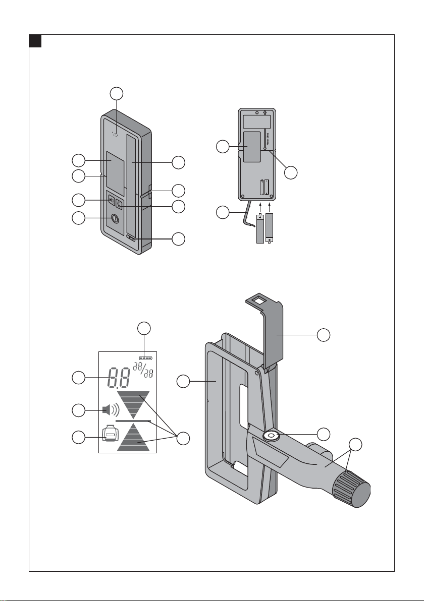
Parts, operating controls and indicators 1
PRA30/PRA31laserreceiver
On/off button
@
Audible signal button
;
Units button
=
Audible signal aperture
%
Receiving area
&
Display area, front
(
Marking notch
)
Reference plane
+
Spirit level
§
Battery compartment cover
/
Display area, rear
:
PRA30/PRA31laserreceiverdisplay
Display showing the position of the receiver relative
·
to the height of the laser plane
Exact distance of the receiver from the laser plane
$
Battery status indicator
£
Volume indicator
|
Rotating laser low energy indicator
¡
PRA 80 laser receiver holder
Protective cage
Q
Catch
W
Mounting arm with rotating grip
E
Spirit level
R
1 General information
1.1 Safety notices and their meaning
DANGER
Draws attention to imminent danger that will lead to
seriousbodilyinjuryorfatality.
WARNING
Draws attention to a potentially dangerous situation that
could lead to serious personal injury or fatality.
CAUTION
Draws attention to a potentially dangerous situation that
could lead to slight personal injury or damage to the
equipment or other property.
NOTE
Draws attention to an instruction or other useful information.
8
1.2 Explanation of the pictograms and other
information
Warning signs
General
warning
Symbols
Read the
operating
instructions
before use
Return waste
material for
recycling.
Loading…
PRA 30
Bedienungsanleitung
Operating instructions Mode demploi Istruzioni duso Manual de instrucciones Manual de instrues Gebruiksaanwijzing Brugsanvisning Bruksanvisning
Bruksanvisning Kyttohje
Hasznlati utasts Instrukcjaobsugi
Nvod k obsluze Nvod na obsluhu Upute za uporabu Navodila za uporabo Instruciunideutilizare KulllanmaTalimat
Lietoanaspamcba Instrukcija Kasutusjuhend
de en fr it es pt nl da sv no fi el hu pl ru cs sk hr sl bg ro tr ar lv lt et uk kk ja ko zh cn
ORIGINAL BEDIENUNGSANLEITUNG
PRA 30 Laserempfnger/Fernbedienung
Lesen Sie die Bedienungsanleitung vor Inbe- triebnahme unbedingt durch. Bewahren Sie diese Bedienungsanleitung im- mer beim Gert auf. Geben Sie das Gert nur mit Bedienungsanlei- tung an andere Personen weiter.
Inhaltsverzeichnis Seite 1 Allgemeine Hinweise 1 2 Beschreibung 2 3 Technische Daten 3 4 Sicherheitshinweise 3 5 Inbetriebnahme 4 6 Bedienung 4 7 Pflege und Instandhaltung 5 8 Entsorgung 6 9 Herstellergewhrleistung Gerte 6 10 FCCHinweis (gltig in USA)/IC-Hinweis (gltig
in Kanada) 7 11 EG-Konformittserklrung (Original) 7
1 Die Zahlen verweisen auf Abbildungen. Die Abbildun- gen finden Sie am Anfang der Bedienungsanleitung.
Im Text dieser Bedienungsanleitung bezeichnet das Ge- rt immer den Laserempfnger PRA 30 (03).
Bedienfeld 1
@ Taste Ein/Aus
; Neigungseingabetaste «Plus»/Richtungstaste «Nach rechts» bzw. «Nach oben» (mit PRA 90)
= Einheitentaste
% Lautstrketaste
& Neigungseingabetaste «Minus»/Richtungstaste «Nach links» bzw. «Nach unten» (mit PRA 90)
( Taste «Automatisches Ausrich- ten»/»berwachungsmodus» (vertikal) (doppelter Tastendruck)
) Detektionsfeld
+ Markierungskerbe
Anzeige
PRA 30 Laserempfnger-Anzeige 2
@ Anzeige der Position des Laserempfngers relativ zur Hhe der Laserebene
; Batteriezustandsanzeige
= Lautstrkeanzeige
% Abstandsanzeige zur Laserebene
1 Allgemeine Hinweise 1.1 Signalwrter und ihre Bedeutung GEFAHR Fr eine unmittelbar drohende Gefahr, die zu schweren Krperverletzungen oder zum Tod fhrt.
WARNUNG Fr eine mglicherweise gefhrliche Situation, die zu schweren Krperverletzungen oder zum Tod fhren kann.
VORSICHT Fr eine mglicherweise gefhrliche Situation, die zu leichten Krperverletzungen oder zu Sachschaden fhren knnte.
HINWEIS Fr Anwendungshinweise und andere ntzliche Informa- tionen.
1.2 Erluterung der Piktogramme und weitere Hinweise
Warnzeichen
Warnung vor allgemeiner Gefahr
Warnung vor tzenden Stoffen
Warnung vor gefhrlicher elektrischer Spannung
Gebotszeichen
Vor Benutzung Bedienungs- anleitung lesen
de
1
Symbole
Abflle der Wiederver- wertung zufhren
Nicht in den Strahl blicken
Ort der Identifizierungsdetails auf dem Gert Die Typenbezeichnung und die Serienkennzeichnung sind auf dem Typenschild Ihres Gerts angebracht. bertragen Sie diese Angaben in Ihre Bedienungsan- leitung und beziehen Sie sich bei Anfragen an unsere Vertretung oder Servicestelle immer auf diese Angaben.
Typ:
Generation: 03
Serien Nr.:
2 Beschreibung 2.1 Bestimmungsgemsse Verwendung Das Gert ermglicht in Kombination mit einem Rotationslaser des Typs PR 30HVS Funktionen per Fernbedienung zu bedienen und den Laserstrahl mittels Detektion zu lokalisieren. Diese Bedienungsanleitung beschrnkt sich auf die Beschreibung der Bedienung des Laserempfngers PRA 30. Fr die Funktionen der Fernbedienung beachten Sie bitte die Angaben in der Bedienungsanleitung des PR 30HVS. Das Gert in Kombination mit dem PR 30HVS ist bestimmt zum Ermitteln, bertragen und berprfen von waagrechten Hhenverlufen, vertikalen und geneigten Ebenen und rechten Winkeln. Anwendungsbeispiele sind das bertragen von Meter- und Hhenrissen, das Bestimmen von rechten Winkeln bei Wnden, das vertikale Ausrichten auf Referenzpunkte und die Erstelllung von geneigten Ebenen. Befolgen Sie die Angaben zu Betrieb, Pflege und Instandhaltung in der Bedienungsanleitung. Bercksichtigen Sie die Umgebungseinflsse. Benutzen Sie das Gert nicht, wo Brand oder Explosionsgefahr besteht. Manipulationen oder Vernderungen am Gert sind nicht erlaubt.
2.2 Merkmale Das Gert kann entweder von Hand gehalten oder mit dem passenden Halter auf Nivellierlatten, Holzlatten, Gestellen usw. angebracht werden.
2.3 Anzeigeelemente HINWEIS Das Displayfeld des Gerts verfgt ber mehrere Symbole zur Darstellung verschiedener Sachverhalte.
Anzeige der Position des Laseremp- fngers relativ zur Hhe der Lasere- bene
Die Anzeige der Position des Laserempfngers in Bezug auf die Hhe der Laserebene zeigt durch einen Pfeil die Richtung an, in die der Laser- empfnger bewegt werden muss, um sich genau auf gleicher Ebene wie der Laser zu befinden.
Batteriezustandsanzeige Die Batteriezustandsanzeige zeigt die Restkapazitt der Batterie an. Lautstrke Wird kein Lautstrkesymbol angezeigt, ist das akustische Signal ausge-
schaltet. Wird ein Balken angezeigt, ist die Lautstrke «Leise» eingestellt. Werden zwei Balken angezeigt, ist die Lautstrke «Normal» eingestellt. Werden drei Balken angezeigt, ist die Lautstrke «Laut» eingestellt.
Abstandsanzeige Zeigt den genauen Abstand des Laserempfngers zur Laserebene in der gewnschten Masseinheit an.
Sonstige Anzeigen Sonstige Anzeigen im Display beziehen sich auf den Rotationslaser PR 30HVS im Rahmen der Fernbedienung. Beachten Sie hierfr die Angaben in der Bedienungsanleitung des PR 30HVS.
2.4 Lieferumfang 1 Laserempfnger/Fernbedienung PRA 30 (03) 1 Bedienungsanleitung PRA 30
de
2
2 Batterien (AA-Zellen) 1 Herstellerzertifikat
3 Technische Daten Technische nderungen vorbehalten!
Operationsbereich Detektion (Durchmesser) Mit PR 30-HVS typisch: 2500 m (6 bis 1600 ft) Akustischer Signalgeber 3 Lautstrken mit der Mglichkeit zur Unterdrckung Flssigkristallanzeige Beidseitig Bereich der Abstandsanzeige 52 mm (2 in) Anzeigebereich der Laserebene 0,5 mm (0.02 in) Lnge des Detektionsfelds 120 mm (5 in) Zentrumsanzeige von Gehuseoberkante 75 mm (3 in) Markierungskerben Auf beiden Seiten Detektionsfreie Wartezeit vor Selbstabschaltung 15 min Abmessungen 160 mm (6.3 in) 67 mm (2.6 in) 24 mm (0.9 in) Gewicht (inklusive Batterien) 0,25 kg (0.6 lbs) Energieversorgung 2 AAZellen Batterielebensdauer (Alkalimangan) Temperatur +20 C (+68 F): ca. 40 h (abhngig von der
Qualitt der Alkalimanganbatterien) Betriebstemperatur -20+50 C (-4 bis +122 F) Lagertemperatur -25+60 C (-13 bis +140 F) Schutzklasse IP 66
(gemss IEC 60529), ausser Batteriefach Falltesthhe1 2 m (6.5 ft) 1 Falltest wurde im Empfngerhalter PRA 83 auf flachen Beton unter Standardumgebungsbedingungen (MIL-STD-810G) durchge- fhrt.
4 Sicherheitshinweise 4.1 Grundlegende Sicherheitsvermerke Neben den sicherheitstechnischen Hinweisen in den einzelnen Kapiteln dieser Bedienungsanleitung sind folgende Bestimmungen jederzeit strikt zu beachten.
4.2 Allgemeine Sicherheitsmassnahmen a) Halten Sie beim Arbeiten andere Personen, ins-
besondere Kinder, vom Wirkungsbereich fern. b) berprfen Sie dasGert vor demGebrauch. Falls
das Gert beschdigt ist, lassen Sie es in einem Hilti Service-Center reparieren.
c) Lassen Sie das Gert nur durch ein Hilti Ser- viceCenter reparieren.
d) Machen Sie keine Sicherheitseinrichtungen un- wirksam und entfernen Sie keine Hinweis- und Warnschilder.
e) Nach einem Sturz oder anderen mechanischen Einwirkungen muss das Gert in einem Hilti Ser- viceCenter berprft werden.
f) Stellen Sie bei der Verwendung mit Adaptern si- cher, dass das Gert richtig eingesetzt ist.
g) Halten Sie das Detektionsfeld sauber, um Fehl- messungen zu vermeiden.
h) Obwohl das Gert fr den harten Baustellenein- satz konzipiert ist, sollten Sie es, wie andere op- tische und elektrische Gerte (Feldstecher, Brille, Fotoapparat) sorgfltig behandeln.
i) Obwohl das Gert gegen den Eintritt von Feuch- tigkeit geschtzt ist, sollten Sie es trockenwi- schen, bevor Sie es im Transportbehlter ver- stauen.
j) Der Betrieb des Gerts in unmittelbarer Nhe der Ohren kann Gehrschden verursachen. Bringen Sie das Gert nicht in unmittelbare Nhe der Oh- ren.
de
3
4.2.1 Elektrisch
a) Die Batterien drfen nicht in die Hnde von Kin- dern gelangen.
b) berhitzen Sie die Batterien nicht und setzen Sie sie nicht einem Feuer aus. Die Batterien knnen ex- plodieren oder es knnen toxische Stoffe freigesetzt werden.
c) Laden Sie die Batterien nicht auf. d) Verlten Sie die Batterien nicht im Gert. e) Entladen Sie die Batterien nicht durch
Kurzschliessen, sie knnen dadurch berhitzen und Verbrennungen verursachen.
f) ffnen Sie die Batterien nicht und setzen Sie sie nicht bermssiger mechanischer Belastung aus.
4.3 Sachgemsse Einrichtung der Arbeitspltze a) Vermeiden Sie, bei Ausrichtarbeiten auf Leitern,
eine abnormale Krperhaltung. Sorgen Sie fr si- cheren Stand und halten Sie jederzeit das Gleich- gewicht.
b) Verwenden Sie das Gert nur innerhalb der defi- nierten Einsatzgrenzen.
c) Messungen durch oder auf Glasscheiben oder durch andere Objekte knnen das Messresultat verflschen.
d) Das Arbeiten mit Messlatten in der Nhe von Hoch- spannungsleitungen ist nicht erlaubt.
4.4 Elektromagnetische Vertrglichkeit Obwohl das Gert die strengen Anforderungen der ein- schlgigen Richtlinien erfllt, kann Hilti die Mglichkeit nicht ausschliessen, dass das Gert durch starke Strah- lung gestrt wird, was zu einer Fehloperation fhren kann. In diesem Fall oder anderen Unsicherheiten mssen Kon- trollmessungen durchgefhrt werden. Ebenfalls kann Hilti nicht ausschliessen dass andere Gerte (z.B. Navigati- onseinrichtungen von Flugzeugen) gestrt werden.
5 Inbetriebnahme
5.1 Batterien einsetzen 3
GEFAHR Setzen Sie keine beschdigten Batterien ein.
GEFAHR Mischen Sie keine neuen und alten Batterien. Verwen- denSie keineBatterien von verschiedenenHerstellern oder mit unterschiedlichen Typenbezeichnungen.
HINWEIS Das Gert darf nur mit Batterien betrieben werden, die gemss internationalen Standards hergestellt wurden.
1. ffnen Sie das Batteriefach des Gerts. 2. Setzen Sie die Batterien in das Gert ein.
HINWEIS Beachten Sie beim Einsetzen die Polaritt der Batterien!
3. Schliessen Sie das Batteriefach.
6 Bedienung
6.1 Gert ein und ausschalten 1
Drcken Sie die Taste Ein/Aus. Beachten Sie, dass alle Fernbedienungstasten des PRA 30 nur mit einem PR 30HVS Rotationslaser funktionieren. Die Funktionen der Tasten entnehmen Sie bitte der Bedienungsanleitung des PR 30HVS.
6.2 Arbeiten mit dem Laserempfnger Der Laserempfnger kann fr Distanzen (Radien) bis 250 m (800 ft) benutzt werden. Die Anzeige des La- serstrahls erfolgt optisch und akustisch.
6.2.1 Arbeiten mit dem Laserempfnger als Handgert
1. Drcken Sie die Taste Ein/Aus. 2. Halten Sie das Gert direkt in die Ebene des rotie-
renden Laserstrahls.
de
4
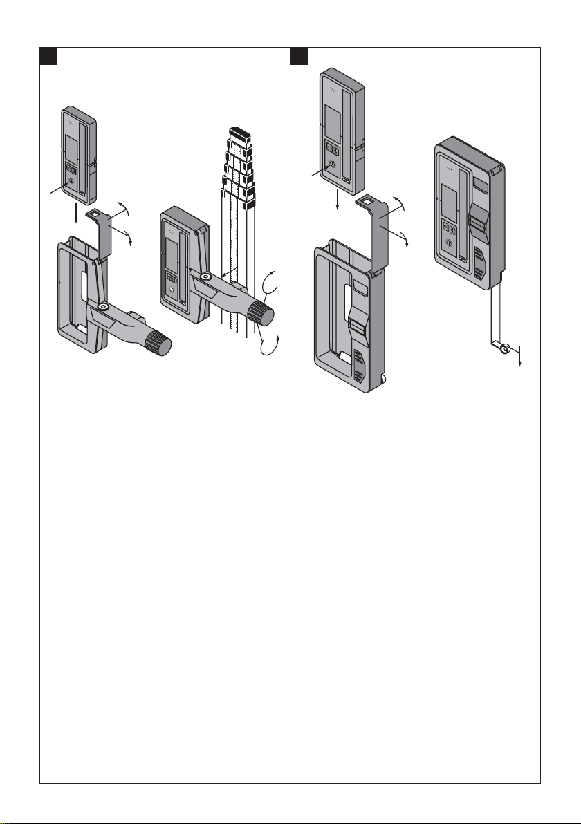
6.2.2 Arbeiten mit dem Laserempfnger im Empfngerhalter PRA 80 4
1. ffnen Sie den Verschluss am PRA 80. 2. SetzenSie dasGert in denEmpfngerhalter PRA 80
ein. 3. Schliessen Sie den Verschluss am PRA 80. 4. Schalten Sie das Gert mit der Taste Ein/Aus ein. 5. ffnen Sie den Drehgriff. 6. Befestigen Sie den Empfngerhalter PRA 80 durch
Schliessen des Drehgriffs sicher an der Teleskop- stange oder Nivellierstange.
7. Halten Sie das Gert mit dem Detektionsfeld direkt in die Ebene des rotierenden Laserstrahls.
6.2.3 Arbeiten mit dem Laserempfnger im Empfngerhalter PRA 83 4
1. Drcken Sie das Gert schrg in die Gummihlle des PRA 83, bis diese das Gert vollstndig umschliesst. Achten Sie darauf, dass sich das Detektionsfeld und die Tasten auf der Vorderseite befinden.
2. Stecken Sie das Gert zusammen mit der Gum- mihlle an das Griffstck. Die magnetische Halte- rung verbindet Hlle und Griffstck miteinander.
3. Schalten Sie das Gert mit der Taste Ein/Aus ein. 4. ffnen Sie den Drehgriff. 5. Befestigen Sie den Empfngerhalter PRA 83 durch
Schliessen des Drehgriffs sicher an der Teleskop- oder Nivellierstange.
6. Halten Sie das Gert mit dem Detektionsfeld direkt in die Ebene des rotierenden Laserstrahls.
6.2.4 Arbeiten mit dem Hhenbertragungsgert PRA 81 4
1. ffnen Sie den Verschluss am PRA 81.
2. Setzen Sie das Gert in das Hhenbertragungsge- rt PRA 81 ein.
3. Schliessen Sie den Verschluss am PRA 81. 4. Schalten Sie das Gert mit der Taste Ein/Aus ein. 5. Halten Sie das Gert mit dem Detektionsfeld direkt
in die Ebene des rotierenden Laserstrahls. 6. Positionieren Sie das Gert so, dass die Abstands-
anzeige «0» anzeigt. 7. Messen Sie den gewnschten Abstand mit Hilfe des
Massbandes.
6.2.5 Einheiteneinstellung Mit der Einheitentaste knnen Sie die gewnschte Ge- nauigkeit der digitalen Anzeige einstellen (mm/cm/aus).
6.2.6 Lautstrkeeinstellung Beim Einschalten des Gerts ist die Lautstrke auf «Nor- mal» eingestellt. Durch Drcken der Lautstrketaste kann die Lautstrke gendert werden. Sie knnen zwischen den vier Optionen «Leise», «Normal», «Laut» und «Aus» whlen.
6.2.7 Menoptionen Drcken Sie beim Einschalten des Gerts fr zwei Se- kunden die Taste Ein/Aus. Die Menanzeige erscheint im Anzeigefeld.
Verwenden Sie die Einheitentaste, um zwischen metri- schen und angloamerikanischen Einheiten umzuschal- ten. Verwenden Sie die Lautstrketaste, um die schnellere Folge des akustischen Signals dem Detektionsbereich oberhalb oder unterhalb der Markierungskerbe zuzuord- nen. Schalten Sie das Gert aus, um die Einstellungen zu speichern.
7 Pflege und Instandhaltung 7.1 Reinigen und trocknen 1. Staub von Oberflche wegblasen. 2. Anzeigefelder bzw. Detektionsfeld nicht mit den Fin-
gern berhren. 3. Nur mit einem sauberen und weichen Tuch reinigen.
Das Tuch wenn ntig mit reinem Alkohol oder etwas Wasser befeuchten. HINWEIS Keine anderen Flssigkeiten verwenden, da diese die Kunststoffteile angreifen knnen.
4. Trocknen Sie Ihre Ausrstung unter Einhaltung der Temperaturgrenzwerte, die in den technischen Da- ten angegeben sind. HINWEIS Achten Sie speziell im Winter/Sommer auf die Temperaturgrenzwerte, wenn Sie Ihre Aus- rstung z. B. im Fahrzeuginnenraum aufbewahren.
7.2 Lagern Nass gewordene Gerte auspacken. Gerte, Transport- behlter und Zubehr trocknen (unter Beachtung der Be-
triebstemperatur) und reinigen. Ausrstung erst wieder einpacken, wenn sie vllig trocken ist. Fhren Sie nach lngerer Lagerung oder lngerem Trans- port Ihrer Ausrstung vorGebrauch eineKontrollmessung durch. Entnehmen Sie vor lngeren Lagerzeiten die Batterien aus dem Gert. Durch auslaufende Batterien kann das Gert beschdigt werden.
7.3 Transportieren Verwenden Sie fr den Transport oder Versand Ihrer Ausrstung entweder die Originalverpackung von Hilti oder eine gleichwertige Verpackung. VORSICHT Nehmen Sie vor dem Transport oder Versand die Batte- rien aus dem Gert.
de
5
7.4 Kalibrieren durch Hilti Kalibrierservice Wir empfehlen die regelmssige berprfung des Sys- tems durch den Hilti Kalibrierservice zu nutzen, um die Zuverlssigkeit gemss Normen und rechtlichen Anfor- derungen gewhrleisten zu knnen. Der Hilti Kalibrierservice steht Ihnen jederzeit zur Ver- fgung. Wir empfehlen Ihnen, das System mindestens einmal jhrlich kalibrieren zu lassen. Im Rahmen des Hilti Kalibrierservice wird besttigt, dass die Spezifikationen des geprften Systems am Tag der
Prfung den technischen Angaben der Bedienungsanlei- tung entsprechen. Bei Abweichungen von den Herstellerangaben wird das gebrauchte Messgert wieder neu eingestellt. Nach der Justierung undPrfungwird eineKalibrierplakette amGe- rt angebracht und mit einem Kalibrierzertifikat schriftlich besttigt, dass das System innerhalb der Herstelleranga- ben arbeitet. Kalibrierzertifikate werden immer bentigt fr Unterneh- men, die nach ISO 900X zertifiziert sind. Ein Hilti Kontakt in Ihrer Nhe gibt Ihnen gerne weitere Auskunft.
8 Entsorgung GEFAHR Bei unsachgemssem Entsorgen der Ausrstung knnen folgende Ereignisse eintreten: Beim Verbrennen von Kunststoffteilen entstehen giftige Abgase, an denen Personen erkranken knnen. Batterien knnen explodieren und dabei Vergiftungen, Verbrennungen, Vertzungen oder Umweltverschmutzung verursachen, wenn sie beschdigt oder stark erwrmt werden. Bei leichtfertigem Entsorgen ermglichen Sie unberechtigten Personen, die Ausrstung sachwidrig zu verwenden. Dabei knnen Sie sich und Dritte schwer verletzen sowie die Umwelt verschmutzen.
Hilti-Gerte sind zu einem hohen Anteil aus wiederverwertbaren Materialien hergestellt. Voraussetzung fr eine Wiederverwertung ist eine sachgemsse Stofftrennung. In vielen Lndern ist Hilti bereits eingerichtet, Ihr Altgert zur Verwertung zurckzunehmen. Fragen Sie den Hilti Kundenservice oder Ihren Verkaufsberater.
Nur fr EU Lnder Werfen Sie elektronische Messgerte nicht in den Hausmll! Gemss Europischer Richtlinie ber Elektro- und Elektronik-Altgerte und Umsetzung in nationales Recht mssen verbrauchte Elektrogerte getrennt gesammelt und einer umweltgerechten Wiederver- wertung zugefhrt werden.
Entsorgen Sie die Batterien nach den nationalen Vorschriften
9 Herstellergewhrleistung Gerte Bitte wenden Sie sich bei Fragen zu den Garantiebedin- gungen an Ihren lokalen HILTI Partner.
de
6
10 FCCHinweis (gltig in USA)/IC-Hinweis (gltig in Kanada) VORSICHT Dieses Gert hat in Tests die Grenzwerte eingehalten, die in Abschnitt 15 der FCC-Bestimmungen fr digitale Ge- rte der Klasse B festgeschrieben sind. Diese Grenzwerte sehen fr die Installation in Wohngebieten einen ausrei- chenden Schutz vor strenden Abstrahlungen vor. Gerte dieser Art erzeugen und verwenden Hochfrequenzen und knnen diese auch ausstrahlen. Sie knnen daher, wenn sie nicht den Anweisungen entsprechend installiert und betrieben werden, Strungen des Rundfunkempfangs verursachen.
Es kann aber nicht garantiert werden, dass bei bestimm- ten Installationen nicht doch Strungen auftreten knnen. Falls dieses Gert Strungen des Radio- oder Fernseh- empfangs verursacht, was durch Aus- und Wiederein- schalten des Gerts festgestellt werden kann, ist der Benutzer angehalten, die Strungen mit Hilfe folgender Massnahmen zu beheben:
Die Empfangsantenne neu ausrichten oder versetzen.
Den Abstand zwischen Gert und Empfnger vergrs- sern.
Das Gert an die Steckdose eines Stromkreises ansch- liessen, der unterschiedlich ist zu dem des Empfngers.
Lassen Sie sich von IhremHndler oder einem erfahrenen Radio- und Fernsehtechniker helfen.
HINWEIS nderungen oder Modifikationen, die nicht ausdrcklich von Hilti erlaubt wurden, knnen das Recht des Anwen- ders einschrnken, das Gert in Betrieb zu nehmen.
Diese Vorrichtung entspricht Paragraph 15 der FCC- Bestimmungen und RSS210 der IC.
Die Inbetriebnahme unterliegt folgenden zwei Bedingun- gen:
Dieses Gert sollte keine schdigende Abstrahlung er- zeugen.
Das Gert muss jegliche Abstrahlung aufnehmen, inklu- sive Abstrahlungen die unerwnschte Operationen be- wirken.
11 EG-Konformittserklrung (Original) Bezeichnung: Laserempfnger/Fernbe-
dienung Typenbezeichnung: PRA 30 Generation: 03 Konstruktionsjahr: 2013
Wir erklren in alleiniger Verantwortung, dass dieses Produkt mit den folgenden Richtlinien und Normen bereinstimmt: bis 19. April 2016: 2004/108/EG, ab 20. April 2016: 2014/30/EU, 2011/65/EU, 1999/5/EG, EN 300 4402 V1.4.1, EN 301 4891 V1.9.2, EN 301 48917 V2.2.1, EN ISO 12100.
Hilti Aktiengesellschaft, Feldkircherstrasse 100, FL9494 Schaan
Paolo Luccini Edward Przybylowicz Head of BA Quality and Process Mana- gement
Head of BU Measuring Systems
Business Area Electric Tools & Acces- sories
BU Measuring Systems
06/2015 06/2015
Technische Dokumentation bei: Hilti Entwicklungsgesellschaft mbH Zulassung Elektrowerkzeuge Hiltistrasse 6 86916 Kaufering Deutschland
de
7
ORIGINAL OPERATING INSTRUCTIONS
PRA 30 laser receiver / remote control
It is essential that the operating instructions are read before the tool is operated for the first time. Always keep these operating instructions to- gether with the tool. Ensure that the operating instructions are with the tool when it is given to other persons.
Contents Page 1 General information 8 2 Description 9 3 Technical data 10 4 Safety instructions 10 5 Before use 11 6 Operation 11 7 Care and maintenance 12 8 Disposal 13 9 Manufacturers warranty — tools 13 10 FCC statement (applicable in US) / IC
statement (applicable in Canada) 13 11 EC declaration of conformity (original) 14
1 These numbers refer to the illustrations. You can find the illustrations at the beginning of the operating instructions. In these operating instructions, the designation the power tool always refers to the PRA 30 (03) laser re- ceiver.
Control panel 1
@ On/off button
; Inclination entry button Plus / Right or Up dir- ection button (with the PRA 90)
= Units button
% Volume button
& Inclination entry button Minus / Left or Down direction button (with the PRA 90)
( Automatic alignment / surveillance mode (ver- tical) button (press button twice)
) Receiving area
+ Marking notch
Display
PRA 30 laser receiver display 2
@ Position of the laser receiver relative to the height of the laser plane
; Battery status indicator
= Volume indicator
% Distance to the laser plane
1 General information 1.1 Safety notices and their meaning DANGER Draws attention to imminent danger that will lead to serious bodily injury or fatality.
WARNING Draws attention to a potentially dangerous situation that could lead to serious personal injury or fatality.
CAUTION Draws attention to a potentially dangerous situation that could lead to slight personal injury or damage to the equipment or other property.
NOTE Draws attention to an instruction or other useful informa- tion.
1.2 Explanation of the pictograms and other information
Warning signs
General warning
Warning: caustic
substances
Warning: electricity
Obligation signs
Read the operating instructions before use.
en
8
Symbols
Return waste material for recycling.
Do not look into the beam.
Location of identification data on the tool The type designation and serial number can be found on the type identification plate on the tool. Make a note of this data in your operating instructions and always refer to it when making an enquiry to your Hilti representative or service department.
Type:
Generation: 03
Serial no.:
2 Description 2.1 Use of the product as directed The device can be used to remotely control the PR 30-HVS rotating laser and to detect and locate the laser beam. These operating instructions apply only to operation of the PRA 30 laser receiver. For information about the remote control functions, please refer to the operating instructions for the PR 30-HVS. In conjunction with the PR 30-HVS, the tool can be used to determine, transfer and check horizontal levels and heights, verticals, inclined planes and right angles. Examples of its uses are: transferring datums and height marks, determining right angles for walls, vertical alignment on reference points and setting out slopes. Observe the information printed in the operating instructions concerning operation, care and maintenance. Take the influences of the surrounding area into account. Do not use the tool where there is a risk of fire or explosion. Modification of the tool or tampering with its parts is not permissible.
2.2 Features The tool can be held by hand or mounted on a leveling staff, timber batten or frame etc., using the applicable holder.
2.3 Indicators NOTE The display incorporates several symbols that indicate various circumstances.
Position of the laser receiver relative to the height of the laser plane
The position of the laser receiver relative to the height of the laser plane is shown by an arrow indicating the direction in which the laser receiver has to be moved in order to bring it exactly into alignment with the laser.
Battery status indicator The battery status indicator shows the remaining battery capacity. Volume level If no volume symbol is shown, the signal tone is switched off. If one seg-
ment is shown, the volume is set to quiet. If two segments are shown, the volume is set to Normal. If three segments are shown, the volume is set to loud.
Offset indicator Shows the exact distance of the laser receiver from the laser plane in the desired unit of measurement.
Other indicators Other indicators in the display refer to the PR 30-HVS rotating laser when controlled remotely. For further information, please refer to the PR 30- HVS operating instructions.
2.4 Items supplied 1 PRA 30 (03) laser receiver / remote control 1 PRA 30 operating instructions 2 Batteries (size AA cells) 1 Manufacturers certificate
en
9
3 Technical data Right of technical changes reserved.
Detection range (area diameter) Typical distance with PR 30-HVS: 2500 m (6 to 1600 ft)
Audible signal generator 3 volume levels plus mute setting Liquid crystal display On both sides Indicator range, distance from zero 52 mm (2 in) Laser plane indication area 0.5 mm (0.02 in) Length of the receiving area 120 mm (5 in) Casing top edge center indicator 75 mm (3 in) Marking notches On both sides Time without detection before automatic power off 15 min Dimensions 160 mm (6.3 in) 67 mm (2.6 in) 24 mm (0.9 in) Weight (including batteries) 0.25 kg (0.6 lbs) Power source 2 AAsize batteries Battery life (alkaline) Temperature +20C (+68 F): Approx. 40 h (depending
on the quality of the alkaline batteries used) Operating temperature range -20+50C (-4 to +122 F) Storage temperature -25+60C (-13 to +140 F) Protection class IP 66
(in accordance with IEC 60529), except battery com- partment
Drop test height1 2 m (6.5 ft) 1 The drop test was carried out using the PRA 83 receiver holder, dropped onto flat concrete under standard ambient conditions (MIL-STD-810G).
4 Safety instructions 4.1 Basic information concerning safety In addition to the information relevant to safety given in each of the sections of these operating instructions, the following points must be strictly observed at all times.
4.2 General safety rules a) Keep other persons, especially children, away
from the area in which the work is being carried out.
b) Check the condition of the tool before use. If the tool is damaged, have it repaired at a Hilti Service Center.
c) Have the tool repaired only at a Hilti service cen- ter.
d) Do not render safety devices ineffective and do not remove information and warning notices.
e) The tool must be checked at a Hilti service center after it has been dropped or subjected to other mechanical stresses.
f) If mounting on an adapter, check that the tool is fitted correctly.
g) Keep the receiving area clean in order to avoid measurement errors.
h) Although the tool is designed for the tough condi- tions of jobsite use, aswith other optical and elec- tronic instruments (e.g. binoculars, spectacles, cameras) it should be treated with care.
i) Although the tool is protected against the entry of moisture, it should be wiped dry before being put away in its transport container.
j) Operation of the tool close to the ears may cause hearing damage. Do not position the tool close to the ears.
4.2.1 Electrical
a) Keep the batteries out of reach of children.
en
10
b) Do not allow the batteries to overheat and do not expose them to fire. The batteries may explode or release toxic substances.
c) Do not charge the batteries. d) Do not solder the batteries into the tool. e) Do not discharge the batteries by short circuiting
as this may cause them to overheat and present a risk of personal injury (burns).
f) Do not attempt to open the batteries and do not subject them to excessive mechanical stress.
4.3 Proper organization of the work area a) Avoid unfavorable body positions when working
on ladders or scaffolding. Make sure you work from a safe stance and stay in balance at all times.
b) Use the tool only within its specified limits. c) Measurements taken through or from panes of glass
or through other objects may be inaccurate. d) Use of the telescopic staff in the vicinity of overhead
high voltage cables is not permissible.
4.4 Electromagnetic compatibility Although the tool complies with the strict requirements of the applicable directives, Hilti cannot entirely rule out the possibility of the tool being subject to interference caused by powerful electromagnetic radiation, leading to incorrect operation. Check the accuracy of the tool by taking measurements by other means when working under such conditions or if you are unsure. Likewise, Hilti cannot rule out the possibility of interference with other devices (e.g. aircraft navigation equipment).
5 Before use
5.1 Inserting the batteries 3
DANGER Do not use damaged batteries.
DANGER Do notmix old and newbatteries. Do notmix batteries of different makes or types.
NOTE The tool may be powered only by batteries manufactured in accordancewith the applicable international standards.
1. Open the tools battery compartment. 2. Insert the batteries in the tool.
NOTE Check to ensure correct polarity when insert- ing the batteries.
3. Close the battery compartment.
6 Operation
6.1 Switching the tool off and on 1
Press the on / off button. Please note that all remote control buttons on the PRA 30 function only in conjunction with a PR 30-HVS rotating laser. For information about the button functions, please refer to the PR 30-HVS operating instructions.
6.2 Working with the laser receiver The laser receiver can be used at distances (radiuses) of up to 250 m (800 ft). The laser beam is indicated visually and by a signal tone.
6.2.1 Using the laser receiver as a hand-held tool 1. Press the on / off button. 2. Hold the tool in the plane of the rotating laser beam.
6.2.2 Working with the laser receiver in the PRA 80 receiver holder 4
1. Open the catch on the PRA 80. 2. Place the tool in the PRA 80 receiver holder. 3. Close the catch on the PRA 80. 4. Switch the tool on by pressing the on/off button. 5. Rotate the grip to bring it into the open position. 6. Secure the PRA 80 receiver holder on the telescopic
staff by tightening the clamping knob. 7. Hold the tool with the receiving area in the plane of
the rotating laser beam.
6.2.3 Working with the laser receiver in the PRA 83 receiver holder 4
1. Push the tool into the rubber sleeve of the PRA 83 at an angle until it fully encloses the tool. Take care to ensure that the receiving area and the buttons are facing the front.
en
11
2. Fit the tool, complete with the rubber sleeve, onto the grip section. The cover and grip section are joined together by the magnetic holder.
3. Switch the tool on by pressing the on/off button. 4. Rotate the grip to bring it into the open position. 5. Secure the PRA 83 receiver holder on the telescopic
staff or leveling staff by tightening the clamping knob.
6. Hold the tool with the receiving area in the plane of the rotating laser beam.
6.2.4 Working with the PRA 81 4
1. Open the locking mechanism on the PRA 81. 2. Insert the tool in the PRA 81 height transfer device. 3. Close the locking mechanism on the PRA 81. 4. Switch the tool on by pressing the on/off button. 5. Hold the tool with the receiving area in the plane of
the rotating laser beam. 6. Position the tool so that the distance display shows
0. 7. Use the measuring tape to measure the desired
offset distance.
6.2.5 Setting the measuring unit The Units button can be used to set the desired accur- acy of the digital display (mm/cm/off).
6.2.6 Volume adjustment The tool is set to Normal volume when switched on. The volume can be adjusted by pressing the Volume button. One of four settings can be selected: Low, Normal, High or Off.
6.2.7 Menu options Press the on/off button for two seconds when switching the tool on. The menu is then shown in the display.
Use the Measuring units button to select metric or U.S. / imperial measuring units. Use the Volume button to assign the more rapid signal tone to the receiving area above or below the marking notch. To save the settings, switch the tool off.
7 Care and maintenance 7.1 Cleaning and drying 1. Blow dust off the surfaces. 2. Do not touch the display areas or the receiving area
with the fingers. 3. Use only a clean, soft cloth for cleaning. If necessary,
moisten the cloth slightly with pure alcohol or a little water. NOTE Do not use any other liquids as these may damage the plastic components.
4. Dry the equipment, observing the maximum tem- peratures given in the technical data. NOTE Especially in summer and winter, take care that the given maximum andminimum temperatures are not exceeded, e.g. when the equipment is stored in a motor vehicle.
7.2 Storage Remove the tool from its case if it has become wet. Dry and clean the tool, its transport container and accessor- ies (while observing the permissible temperature range). Repack the equipment only once it is completely dry. Check the accuracy of the equipment before it is used after a long period of storage or transportation. Remove the batteries from the tool before storing it for a long period. Leaking batteries may damage the tool.
7.3 Transport Use the original Hilti packaging or packaging of equivalent quality for transporting or shipping your equipment. CAUTION Remove the batteries from the tool before transporting or shipping it.
7.4 Calibration by the Hilti Calibration Service We recommend that the system is checked by the Hilti Calibration Service at regular intervals in order to verify its reliability in accordance with standards and legal re- quirements. Use can be made of the Hilti Calibration Service at any time, We recommend that the system is calibrated at least once a year The Calibration Service provides confirmation that the system is in conformance, on the day it is tested, with the specifications given in the operating instructions. In the event of deviation from themanufacturer’s specific- ation, the used tool will be readjusted. After checking and adjustment, a calibration sticker applied to the system unit and a calibration certificate provide written verific- ation that the system operates in accordance with the manufacturers specification. Calibration certificates are always required by companies certified according to ISO 900x. The Hilti representative in your local region will be pleased to provide further information.
en
12
8 Disposal DANGER Improper disposal of the equipment may have serious consequences: The burning of plastic components generates toxic fumes which may present a health hazard. Batteries may explode if damaged or exposed to very high temperatures, causing poisoning, burns, acid burns or environmental pollution. Careless disposal may permit unauthorized and improper use of the equipment. This may result in serious personal injury, injury to third parties and pollution of the environment.
Most of the materials from which Hilti tools or appliances are manufactured can be recycled. The materials must be correctly separated before they can be recycled. In many countries, Hilti has already made arrangements for taking back old tools and appliances for recycling. Ask Hilti customer service or your Hilti representative for further information.
For EC countries only Do not dispose of electronic measuring tools or appliances together with household waste. In observance of the European Directive on waste electrical and electronic equipment and its imple- mentation in accordance with national law, electrical appliances that have reached the end of their life must be collected separately and returned to an environmentally compatible recycling facility.
Dispose of the batteries in accordance with national regulations.
9 Manufacturers warranty — tools Please contact your local Hilti representative if you have questions about the warranty conditions.
10 FCC statement (applicable in US) / IC statement (applicable in Canada) CAUTION This equipment has been tested and found to comply with the limits for a class B digital device, pursuant to part 15 of the FCC rules. These limits are designed to provide reasonable protection against harmful interference in a residential installation. This equipment generates, uses, and can radiate radiofrequency energy and, if not installed and used in accordance with the instructions, may cause harmful interference to radio communications.
However, there is no guarantee that interference will not occur in a particular installation. If this equipment does cause harmful interference to radio or television recep- tion, which can be determined by turning the equipment on and off, the user is encouraged to try to correct the interference by one or more of the following measures:
Re-orient or relocate the receiving antenna.
Increase the distance between the equipment and re- ceiver.
Connect the equipment to a power outlet on a circuit different from that to which the receiver is connected.
Consult the dealer or an experienced TV/radio technician for assistance.
NOTE Changes or modifications not expressly approved by Hilti may restrict the users authorization to operate the equipment.
This device complies with part 15 of the FCC Rules and RSS-210 of the IC.
en
13
Operation is subject to the following two conditions:
This device shall cause no cause harmful interference.
This device must accept any interference received, in- cluding interference that may cause undesired operati
Table of Contents
- PRA 30 Laser Receiver
- General information
- Description
- Technical data
- Safety instructions
- Beforeuse
- Operation
- Care and maintenance
- Disposal
- References
- Read User Manual Online (PDF format)
- Download This Manual (PDF format)
PRA 30 Laser Receiver
Instruction Manual
PRA 30 Laser Receiver


It is essential that the operating instructions are read before the tool is
operated for the first time.
Always keep these operating instructions together with the tool.
Ensure that the operating instructions are with the tool when it is given to
other persons.
These numbers refer to the corresponding illustrations.
The illustrations can be found on the fold-out cover pages. Keep these pages
open while studying the operating instructions.
In these operating instructions, the designation “the tool” always refers to
the PRA 30 / PRA 31 laser receiver.
Parts, operating controls and indicators
PRA30/PRA31laserreceiver
-
On/off button
-
Audible signal button
-
Units button
-
Audible signal aperture
-
Receiving area
-
Display area, front
-
Marking notch
-
Reference plane
-
Spirit level
-
Battery compartment cover
-
Display area, rear
PRA30/PRA31 laser receiver display -
Display showing the position of the receiver relative to the height of the laser plane
-
Exact distance of the receiver from the laser plane
-
Battery status indicator
-
Volume indicator
-
Rotating laser low energy indicator
PRA 80 laser receiver holder -
Protective cage
-
Catch
-
Mounting arm with rotating grip
-
Spirit level
General information
1.1 Safety notices and their meaning
DANGER
Draws attention to imminent danger that will lead to
seriousbodilyinjuryorfatality.
WARNING
Draws attention to a potentially dangerous situation that could lead to
serious personal injury or fatality.
CAUTION
Draws attention to a potentially dangerous situation that could lead to slight
personal injury or damage to the equipment or other property.
NOTE
Draws attention to an instruction or other useful information.
1.2 Explanation of the pictograms and other information
Warning signs
General warning
Symbols Location of identification data on the tool
The type designation and serial number can be found on the type identification
plate on the tool. Make a note of this data in your operating instructions and
always refer to it when making an enquiry to your Hilti representative or
service department.
Type:……..
Generation: 01…………..
Serial no.:……………………………….
Description
2.1 Use of the product as directed
The Hilti PRA 30 / 31 laser receiver is designed to detect the laser beam from
rotating lasers.
Observe the information printed in the operating instructions concerning
operation, care and maintenance.
Take the influences of the surrounding area into account. Do not use the tool
where there is a risk of fire or explosion. Modification of the tool or
tampering with its parts is not permissible.
2.2 Features
The tool can either be held by hand or, using the corresponding holder,
mounted on a measuring staff, telescopic staff, leveling staff, wooden batten
or frame etc.
2.3 Indicators
NOTE
The display of the PRA 30 / 31 laser receiver uses several symbols to indicate
various modes or statuses.
Display showing the position of the eceiver relative to the height of the
laser plane| The position of the receiver relative to the height of the laser
plane is shown by an arrow indicating the direction in which the receiver has
to be moved in order to bring it exactly into alignment with the laser.
—|—
Battery status indicator| The battery status indicator shows the remaining
battery capacity.
Volume level| When no volume level symbol is visible in the display, the
volume level is set to zero (off). If 1 column is shown, the volume is set to
“quiet”. If 2 columns are shown, the volume is set to “normal”. If 3 columns
are shown, the volume is set to “loud”.
PRE 3 battery status indicator| The PRE 3 symbol is shown in the display (only
if the PRA 30 / 31 is receiving a signal from the PRE 3) when the PRE 3
battery requires charging.
Units indicator| Shows the exact distance of the receiver from the laser plane
in the desired measuring units.
2.4 Items supplied
- 1 PRA30/PRA31laserreceiver
- 1 Operating instructions
- 2 Batteries (size AA cells)
- 1 Manufacturer’s certificate
Technical data
Right of technical changes reserved.
| Detection range (area diameter) | 2…400 m (6 to 1300 ft) |
|---|---|
| Laser plane indication area | ± 0.5 mm (0.02 in) |
| Audible signal generator | 3 volume levels plus mute setting |
| Liquid crystal display | On both sides |
| Receiving range | 120 mm (5 in) |
| Center indication from top edge of casing | 75 mm (3 in) |
| — | — |
| Marking notches | On both sides |
| Automatic power-off | When no beam is detected: 15 min |
| Dimensions | 160 mm (6.5″) X 67 mm (2.6″) X 27 mm (0.9″) |
| Weight (including batteries) | 0.25 kg (0.6 lbs) |
| Power source | 2 AA‑size batteries |
| Battery life (alkaline-manganese) | Temperature +20°C (+68 °F): 50 h |
| Operating temperature range | -20…+50°C (-4°F to 122°F) |
| Storage temperature | -25…+60°C (-13 °F to 140 °F) |
| Protection class | IP 56 in accordance with IEC 529 |
Safety instructions
4.1 Basic information concerning safety
In addition to the information relevant to safety given in each of the
sections of these operating instructions, the following points must be
strictly observed at all times.
4.2 General safety rules
a) Keep other persons, especially children, away from the area in which the
work is being carried out.
b) Check the condition of the tool before use. If the tool is found to be
damaged, have it repaired at a Hilti service center.
c) Do not render safety devices ineffective and do not remove information and
warning notices.
d) The tool must be checked at a Hilti service center after it has been
dropped or subjected to other mechanical stresses.
e) If mounting on an adapter, check that the tool is fitted correctly.
f) To avoid measurement errors, the receiving area must be kept clean.
g) Although the tool is designed for the tough conditions of jobsite use, as
with other optical and electronic nstruments (e.g. binoculars, spectacles,
cameras) it should be treated with care.
h) Although the tool is protected to prevent entry of dampness, it should be
wiped dry each time before being put away in its transport container.
i) To avoid hearing damage, hold the tool as far away as possible from your
ear (and other per- sons’ ears).
4.2.1 Electrical
a) Keep the batteries out of reach of children.
b) Do not allow the batteries to overheat and do not expose them to fire. The
batteries may explode or release toxic substances.
c) Do not charge the batteries.
d) Do not solder the batteries into the tool.
e) Do not discharge the batteries by short circuiting as this may cause them
to overheat and present a risk of personal injury (burns).
f) Do not attempt to open the batteries and do not subject them to excessive
mechanical stress.
4.3 Proper organization of the work area
a) Avoid unfavorable body positions when working on ladders or scaffolding.
Make sure you work fromasafestanceandstayinbalanceatall times.
b) Measurements taken through or from panes of glass or through other objects
may be inaccurate.
c) Use the tool only within its specified limits.
d) Use of the telescopic staff in the vicinity of over- head high voltage
cables is not permissible.
4.4 Electromagnetic compatibility
Although the tool complies with the strict requirements of the applicable
directives, Hilti cannot entirely rule out the possibility of the tool being
subject to interference caused by powerful electromagnetic radiation, leading
to incorrect operation. Check the accuracy of the tool by taking measurements
by other means when working under such conditions or if you are unsure.
Likewise, Hilti cannot rule out the possibility of interference with other
devices (e.g. aircraft navigation equipment).
Beforeuse
5.1 Inserting the batteries
CAUTION
Do not use damaged batteries.
DANGER
Do not mix old and new batteries. Do not mix batteries of different makes or
types.
NOTE
Only batteries recommended by Hilti may be used to power the tool.
Operation
6.1 Switching the tool off and on
Press the on/off button.
6.2 Working with the tool
The PRA 30 / 31 laser receiver can be used at distances (radiuses) of up to
200 m (650 ft). The laser beam is indicated visually and by an audible signal.
6.2.1 Using the laser receiver as a hand-held tool
- Press the on/off button.
- Hold the PRA 30 / 31 directly in the plane of the rotating laser beam.
The laser beam is indicated by visual and audible signals.
6.2.2 Working with the laser receiver in the PRA 80 receiver holder
- Open the catch on the PRA 80.
- Insert the PRA 30 / 31 laser receiver in the PRA 80 laser receiver holder.
- Close the catch on the PRA 80.
- Switch the laser receiver on by pressing the on / off button.
- Rotate the grip to bring it into the open position.
- Secure the PRA 80 receiver holder on the telescopic staff or leveling staff by turning the rotating grip.
- Hold the PRA 30 / 31 with the receiving window directly in the plane of the rotating laser beam. The laser beam is indicated by visual and audible signals.
6.2.3 Working with the PRA 81
- Open the locking mechanism on the PRA 81.
- Insert the PRA 30 / 31 laser receiver in the PRA 81 height transfer device.
- Close the locking mechanism on the PRA 81.
- Switch the laser receiver on by pressing the on / off button.
- Hold the PRA 30 / 31 with the receiving window directly in the plane of the rotating laser beam. The laser beam is indicated by visual and audible signals.
- Use the measuring tape to measure the desired offset distance.
6.2.4 Menu options
When switching the PRA 30 / 31 on, press and hold the on / off button for two
seconds.
The menu is then shown in the display.
Use the “units” button to switch between metric and imperial units.
Use the “volume” button to assign the higher-pitched signal to the upper or
lower area of the receiving window.
To save the settings, switch the PRA 30 / PRA 31 off.
6.2.5 Setting the measuring unit
The “units” button can be used to set the desired meas- uring unit according
to the country of use (mm / cm / off) or (¹⁄₈in / ¹⁄₁₆in / off).
6.2.6 Setting the volume of the audible signal
The tool is set to “normal” volume when switched on. The volume can be
adjusted from “normal” to “loud” by pressing the audible signal button. Press
the button again to switch the signal off and press it once more to set the
signal to “quiet”.
Care and maintenance
7.1 Cleaning and drying
-
Blow dust off the surfaces.
-
Do not touch the display areas or the receiving window with the fingers.
-
Use only a clean, soft cloth for cleaning. If necessary, moisten the cloth slightly with pure alcohol or a little water.
NOTE Do not use any other liquids as these may damage the plastic
components. -
Observe the temperature limits when storing your equipment. This is particularly important in winter /summer if the equipment is kept insidea motor vehicle (25°C to +60°C / -22°F to +140°F).
7.2 Storage
Remove the tool from its case if it has become wet.
The tool, its carrying case and accessories should be cleaned and dried (at
maximum 40°C / 104°F). Repack the equipment only once it has dried completely
and then store it in a dry place.
Check the accuracy of the equipment before it is used after a long period of
storage or transportation.
Remove the batteries from the tool before storing it for a long period.
Leaking batteries may damage the tool.
7.3 Transport
Use the Hilti toolbox or packaging of equivalent quality
fortransportingorshippingyourequipment.
DANGER
Always remove the batteries before transporting the tool.
7.4 Hilti calibration service
We recommend that the tool is checked by the Hilti calibration service at
regular intervals in order to verify its reliability in accordance with
standards and legal require- ments.
Disposal
DANGER
Improper disposal of the equipment may have serious consequences:
The burning of plastic components generates toxic fumes which may present a
health hazard.
Batteries may explode if damaged or exposed to very high temperatures, causing
poisoning, burns, acid burns or environmental pollution.
Careless disposal may permit unauthorized and improper use of the equipment.
This may result in serious personal injury, injury to third parties and
pollution of the environment.
Most of the materials from which Hilti tools or appliances are manufactured
can be recycled. The materials must be correctly separated before they can be
recycled. In many countries, Hilti has already made arrangements for taking
back old tools and appliances for recycling. Ask Hilti customer service or
your Hilti representative for further information.
For EC countries only
Do not dispose of electrical appliances together with household waste.
In observance of the European Directive on waste electrical and electronic
equipment and its implementation in accordance with national law, electrical
appliances that have reached the end of their life must be collected
separately and returned to an environmentally compatible recycling facility.
Dispose of the batteries in accordance with national regulations. Please help
us to protect the environment.
Manufacturer’s warranty – tools
Hilti warrants that the tool supplied is free of defects in
materialandworkmanship.Thiswarrantyisvalidsolong as the tool is operated and
handled correctly, cleaned and serviced properly and in accordance with the
Hilti Operating Instructions, and the technical system is maintained.
This means that only original Hilti consumables, components and spare parts
may be used in the tool. This warranty provides the free-of-charge repair or
replacement of defective parts only over the entire lifespan of the tool.
Parts requiring repair or replacement as a result of normal wear and tear are
not covered by this warranty.
Additional claims are excluded, unless stringent national rules prohibit such
exclusion. In particular, Hilti is not obligated for direct, indirect,
incidental or consequential damages, losses or expenses in connection with, or
by reason of, the use of, or inability to use the tool for any purpose.
Implied warranties of merchantability or fitness for a particular purpose are
specifically excluded.
For repair or replacement, send the tool or related parts immediately upon
discovery of the defect to the address of the local Hilti marketing
organization provided. This constitutes Hilti’s entire obligation with regard
to warranty and supersedes all prior or contemporaneous comments and oral or
written agreements concerning arranties.
FCC statement (applicable in USA)
CAUTION
This equipment has been tested and found to comply with the limits for a class
B digital device, pursuant to part 15 of the FCC rules. These limits are
designed to provide reasonable protection against harmful interference in a
residential installation. This equipment generates, uses, and can radiate
radiofrequency energy and, if not installed and used in accordance with the
instructions, may cause harmful interference to radio communications.
However, there is no guarantee that interference will not occur in a
particular installation. If this equipment does cause harmful interference to
radio or television reception, which can be determined by turning the
equipment on and off, the user is encouraged to try to correct the
interference by one or more of the following measures: Re-orient or relocate
the receiving antenna. Increase the distance between the equipment and
receiver. Consult the dealer or an experienced TV/radio technician for
assistance.
NOTE
Changes or modifications not expressly approved by the party responsible for
compliance could void the user’s authority to operate the equipment.
EC declaration of conformity (original)
| Designation: | Remote control / laser receiver |
|---|---|
| Type: | PRA 30 / PRA 31 |
| Generation: | 1 |
| Year of design: | 2008/2009 |
We declare, on our sole responsibility, that this product complies with the
following directives and standards:
2011/65/EU, 2006/95/EC, 2004/108/EC.
Hilti Corporation, Feldkircherstrasse 100, FL‑9494 Schaan
Paolo Luccini
Head of BA Quality and Process Management
Business Area Electric Tools & Accessories 01/2012 Matthias Gillner
Executive Vice President Business Area Electric
Tools & Accessories 01/2012
Technical documentation filed at:
Hilti Entwicklungsgesellschaft mbH Zulassung Elektrowerkzeuge Hiltistrasse 6
86916 Kaufering Deutschland
Hilti Corporation
LI-9494 Schaan
Tel.: +423 / 234 21 11
Fax:+423 / 234 29 65
www.hilti.com
Hilti = registered trademark of Hilti Corp., Schaan
W 3603 | 0313 | 00-Pos. 1 | 1
Printed in Germany © 2013
Right of technical and programme changes reserved S. E. & O.
368229 / A2
References
- Power Tools, Fasteners and Software for Construction — Hilti USA — Hilti USA
- Manual-Hub.com – Free PDF manuals!
Read User Manual Online (PDF format)
Read User Manual Online (PDF format) >>
Download This Manual (PDF format)
Download this manual >>
Document Download |
‹
›
Hilti PRA 30 Manual Online:
3.65,
1748
votes
Hilti PRA 30 User Manual
Hilti PRA 30 User Guide
Hilti PRA 30 Online Manual
Text of Hilti PRA 30 User Guide:
More Instructions:
|
Hilti PRA 30 Operating instructions manual
|
DOWNLOAD | |
|
Hilti PRA 30 Operating instructions manual
|
DOWNLOAD |
Related Products and Documents (Power Tool):
-
Hilti DX 76 Power Tool Original operating instructions
DX 76
hilti/dx-76.pdf, 75 -
Hilti ST 2500 Power Tool Operating instructions manual
ST 2500
hilti/st-2500.pdf, 16 -
Hilti DX 36 Power Tool Operating instructions manual
DX 36
hilti/dx-36.pdf, 332 -
Hilti DX 860-HSN Power Tool Operating instructions manual
DX 860-HSN
hilti/dx-860-hsn.pdf, 16 -
Hilti DX 351 BT Power Tool Operating instructions manual
DX 351 BT
hilti/dx-351-bt.pdf, 20 -
Hilti TE106 Power Tool Operating instructions manual
TE106
hilti/te106.pdf, 53 -
Hilti PRE 3 Power Tool Operating instructions manual
PRE 3
hilti/pre-3.pdf, 17 -
Hilti AG 125-A22 Power Tool Manual
AG 125-A22
hilti/ag-125-a22.pdf, 26
Comparable Devices:
| # | Manufacturer | Model | Document Type | File | Updated | Pages | Size |
|---|---|---|---|---|---|---|---|
| 1 | Whip Mix | Pro 200 | Operator’s manual | whip-mix/pro-200-EM3.pdf | 20 Feb 2025 | 32 | |
| 2 | Beam | iridium IntelliDOCK 9555 | Quick start manual | beam/iridium-intellidock-9555-K4K.pdf | 30 Nov 2024 | 2 | |
| 3 | Astone | Xinc FM | Operation & user’s manual | astone/xinc-fm-3AJ.pdf | 24 Feb 2024 | 18 | 1.69 Mb |
| 4 | Black & Decker | GR9040B | Manual | black-decker/gr9040b-K1P.pdf | 07 Feb 2024 | 2 | |
| 5 | Vixen | AM-OO-3842 | Specifications | vixen/am-oo-3842-V1Q.pdf | 28 Dec 2023 | 1 | 2.25 Mb |
| 6 | Airwell | AWAU-YDV280-H13 | Service manual | airwell/awau-ydv280-h13-W48.pdf | 29 Dec 2023 | 187 |
Similar Resources:
Power Tool Instructions:
-
KSR Moto Motorcycle TRIGGER 50
TRIGGER 50 (Motorcycle ePDF User Guide, #26E9Q8)
TRIGGER 50, 152
-
ObboMed Kitchen Appliances SH-4200
SH-4200 (Kitchen Appliances ePDF User Manual, #QSAJK3)
SH-4200, 7
-
Philips TV MDl .2E
TV #72QOH1
MDl .2E, 84
-
TiVo DVR Series2
TiVo DVR Viewer’s manual (File: tivo-series2-dvr-156, 05/12/2024)
Series2, 156
-
HP Desktop TouchSmart 520-1200
HP Product User Guide: TouchSmart 520-1200 PDF Getting started — 685D85
TouchSmart 520-1200, 38
-
Rowenta Vacuum Cleaner RO81xx series
RO81xx series Operation & user’s manual — Q2HDLR
RO81xx series, 46
-
brennenstuhl Two-Way Radio PMR TRX 3000
PMR TRX 3000 User handbook manual — UJD44K
PMR TRX 3000, 92
-
Philips CRT TV 21PT6446
PDF Guide (@4AD8F3), Philips 21PT6446 CRT TV (Monday 24-03-2025)
21PT6446, 3
-
Depaepe Telecom Telephone PREMIUM 100
Depaepe Telecom PREMIUM 100 Telephone Operation & user’s manual
PREMIUM 100, 17
-
Viessmann Control Unit SDIO
PDF User Manual (@V65I4B), Viessmann SDIO Control Unit (Thursday 13-02-2025)
SDIO, 40
-
MSI Motherboard 970A-G45 series
MSI 970A-G45 series Manual (Doc Type: Motherboard Operation & user’s manual)
970A-G45 series, 138
-
Audiotec Fischer Signal Processors HELIX DSP.2
HELIX DSP.2 (Signal Processors ePDF User Guide, #7A2I42)
HELIX DSP.2, 24