
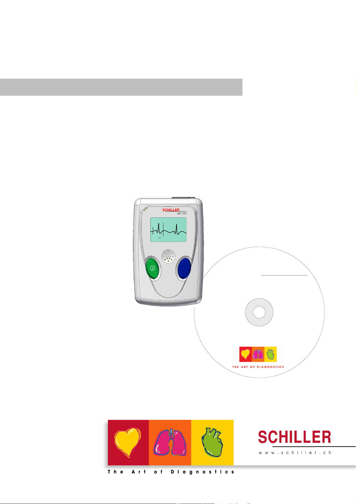
MT-101/MT-200
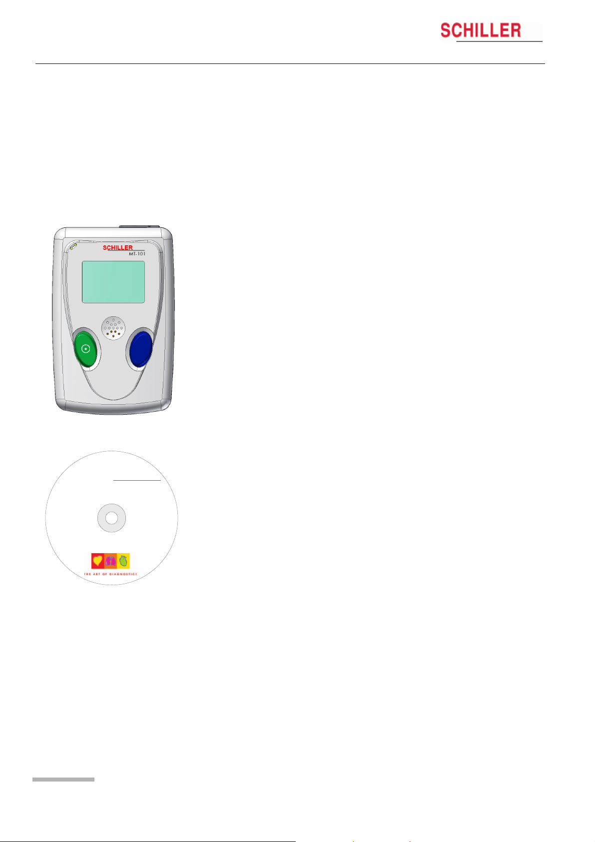
Microvit MT-101 Holter and
MT-200 Evaluation Software
ECG CHANNEL 1
SPEED x1 CHAN2
t
w
f
o
a
S
R
E
L
L
I
H
C
S
r
o
f
s
t
h
g
i
r
y
t
r
e
p
o
r
p
l
a
i
c
r
e
m
m
o
c
d
n
a
l
a
i
r
t
s
u
d
n
i
l
l
A
.
s
e
m
a
N
e
SDS-200 2.01
d
a
r
T
SDS-104 2.01
d
n
SEMA-200 1.81
a
s
k
SEMA-COMM 1.80
r
a
M
MT-190/200 1.80
e
d
MS-3 2.03
a
r
T
BR-102 2.40
d
e
r
Demo Sema-200
e
t
s
i
Demo MT-200
g
e
r
System Software
e
r
Release Notes
Ea
P
Acrobat Reader 4.0
O
C
S
I
N
I
M
d
n
a
A
For further information please visit our homepage
M
E
S
,
www.schiller.ch or send an e-mail to sales@schiller.ch
S
U
G
R
A
,
T
I
V
O
N
O
S
,
T
I
V
O
R
C
I
M
,
T
I
V
O
R
I
P
SCHILLER
SWITZERLAND
S
,
T
I
V
O
I
D
R
A
C
,
R
E
L
L
I
H
C
S
r
e
o
n
t
h
i
s
C
D
b
e
l
o
n
g
t
o
S
C
H
I
L
LE
R
A
G
,
S
w
i
t
z
e
r
l
a
n
d
.
A
l
l
r
i
g
h
t
s
r
e
s
e
r
v
e
d
.
Ó
S
C
H
I
L
L
E
R
A
G
,
C
H
—
6
3
4
Part No. 2.100256
Version x.xx
e
n
a
m
e
s
b
e
l
o
n
g
t
o
t
h
e
i
r
r
e
s
p
e
c
t
i
v
e
h
o
l
d
e
r
s
.
1
B
a
a
r
,
S
w
i
t
z
e
r
l
a
n
d
.
A
l
l
o
t
h
e
r
s
t
a
t
e
m
e
n
t
s
a
n
d
t
r
a
d
Art. no.: 2.510492 rev.: b *2.510492*
User Guide

Sales and Service Information
The SCHILLER sales and service centre network is world-wide. For the address
of your local distributor, contact your nearest SCHILLER subsidiary. A complete
list of all distributors and subsidiaries is provided on our Internet site: http://
www.schiller.ch
Sales information can also be obtained from:
sales@schiller.ch
Headquarters Address
SCHILLER AG Phone: +41 (0) 41 766 42 42
Altgasse 68 Fax: +41 (0) 41 761 08 80
CH-6341 Baar, Switzerland E-mail: sales@schiller.ch
Web: www.schiller.ch
Article no.: 2.510492 rev.: b
Issue date: 29.07.04

MT-101/MT-200
User Guide
Content
1 General and Safety Notes …………………… 5
1.1 Physician’s Responsibility …………………………………………. 5
1.2 Intended Use ………………………………………………………………. 5
1.3 Organisational Measures…………………………………………….. 5
1.4 Operational Precautions ……………………………………………… 6
1.5 Safety Equipment ……………………………………………………….. 6
1.6 Precautions for Operation with other Devices ……………… 6
1.7 Maintenance……………………………………………………………….. 6
1.8 Safety Symbols and Pictograms………………………………….. 7
2 Introduction ……………………………………….8
2.1 MT-101/200 Range of Application ………………………………… 8
2.2 MT-101 Components and Operation …………………………… 10
2.3 Operating and Display Elements ……………………………….. 11
2.3.1 Switching on…………………………………………………………………………. 11
2.3.2 Switching off…………………………………………………………………………. 11
2.3.3 Battery display………………………………………………………………………. 11
2.3.4 Status display……………………………………………………………………….. 11
2.4 MT-101 Menu Structure……………………………………………… 12
2.4.1 Menu Overview …………………………………………………………………….. 12
2.5 Initial Operation ………………………………………………………… 13
2.5.1 Unpacking ……………………………………………………………………………. 13
2.5.2 Inserting/changing the battery…………………………………………………. 13
3 Preparing a Holter Recording …………… 14
3.1 Position of the Electrodes …………………………………………. 14
3.2 Commencing a Holter Recording……………………………….. 16
3.2.1 During the Recording and Patient Information …………………………… 17
3.3 Taking an Extended Recording (Longer than 24 hours). 17
4 Transferring a Recording to the PC …… 18
4.1 Data Transmission to PC from MT-101……………………….. 18
4.2 Data transmission to PC with Memory Card Reader……. 18
5 Displaying an ECG Signal ………………… 19
Art. no.: 2.510492 rev.: b
5.1 Starting a Recording from the MT-200 Program………….. 19
5.1.1 Pacemaker…………………………………………………………………………… 21
5.2 Transmission Problems…………………………………………….. 22
5.2.1 Checking the connection………………………………………………………… 23
6 Viewing and Editing a Recording ……… 24
6.1 Icons ………………………………………………………………………… 24
6.1.1 View icons……………………………………………………………………………. 25
6.1.2 Function icons………………………………………………………………………. 26
Page 1

MT-101/MT-200
User Guide
6.1.3 Tool icons in rhythm and zoom views ………………………………………. 27
6.2 Accessing and Opening Files ……………………………………. 28
6.3 Event & Zoom Views …………………………………………………. 29
6.4 Analysis Summary ……………………………………………………. 31
6.5 Event Samples View………………………………………………….. 33
6.6 ECG View………………………………………………………………….. 35
6.6.1 Selecting Channels for Display ……………………………………………….. 36
6.6.2 Selecting Channels for Analysis………………………………………………. 36
6.6.3 Auto Scrolling……………………………………………………………………….. 36
6.7 Event Chart ………………………………………………………………. 37
6.8 Heart Rate View ………………………………………………………… 38
6.9 ST Trend View…………………………………………………………… 39
6.10 Template Matching ……………………………………………………. 41
6.10.1 Detailed Overview of the Template Classes ……………………………… 43
6.11 Pacemaker Templates……………………………………………….. 45
6.11.1 Template classes ………………………………………………………………….. 46
6.12 Heart Rate Variability ………………………………………………… 49
6.13 Heart Rate Trend……………………………………………………….. 51
6.13.1 Jumping to the max/min Heart Rate or max/min NN Interval……….. 51
6.13.2 Redefining the Max/Min Heart Rate and NN Interval ………………….. 51
6.14 Reclassifying/Editing a QRS Complex ……………………….. 52
6.15 Analysing/Re-analysing the Recording………………………. 54
6.16 Analysing Options…………………………………………………….. 56
6.16.1 Arrhythmias………………………………………………………………………….. 56
6.16.2 Manually Defining Arrhythmias ……………………………………………….. 56
6.16.3 ST-episodes…………………………………………………………………………. 57
6.16.4 Templates ……………………………………………………………………………. 57
6.16.5 Mode …………………………………………………………………………………… 57
6.17 Editing Patient Data/Recording………………………………….. 58
6.18 Printing …………………………………………………………………….. 61
6.18.1 Print preview / Printing a specific page …………………………………….. 61
6.18.2 Obtaining a printout:………………………………………………………………. 62
6.18.3 Printing a selected half hour ECG segment ………………………………. 62
7 Miscellaneous Functions ………………….. 63
7.1 E-Mail and PDF Functions …………………………………………. 63
7.1.1 PDF files with Acrobat Reader ………………………………………………… 63
7.1.2 Editing PDF files……………………………………………………………………. 63
7.2 Saving a Recording …………………………………………………… 64
7.2.1 Saving a recording in MT-200 or PDF format ……………………………. 64
7.2.2 Sending a recording by e-mail ………………………………………………… 65
Art. no.: 2.510492 rev.: b
7.2.3 Importing recordings ……………………………………………………………… 65
7.2.4 Exporting recordings ……………………………………………………………… 65
7.3 Deleting a Recording…………………………………………………. 66
7.4 Accelerator Keys ………………………………………………………. 67
8 System Settings and Options …………… 68
8.1 Print Formats ……………………………………………………………. 68
8.1.1 Templates ……………………………………………………………………………. 68
8.1.2 Event samples………………………………………………………………………. 69
8.1.3 Full disclosure (1, 2 or 3 channel) ……………………………………………. 69
Page 2

MT-101/MT-200
User Guide
8.1.4 User-defined print formats………………………………………………………. 70
8.2 Heart Rate Trend……………………………………………………….. 72
8.3 Amplitude/Speed ………………………………………………………. 73
8.4 Pacemaker Templates……………………………………………….. 74
8.5 System Settings………………………………………………………… 75
8.5.1 Print setup……………………………………………………………………………. 75
8.5.2 Units and language ……………………………………………………………….. 75
8.5.3 Directories……………………………………………………………………………. 76
8.5.4 Data storage mode (auto delete) …………………………………………….. 76
8.5.5 USB / AT-card Connection and Test transmission Mode…………….. 76
8.5.6 GDT…………………………………………………………………………………….. 77
8.5.7 Office Address………………………………………………………………………. 77
8.6 User Identification …………………………………………………….. 78
9 Maintenance ……………………………………..79
9.1 Visual Inspection ………………………………………………………. 79
9.2 Cleaning the device and cable assemblies …………………. 80
9.2.1 Cleaning the device, electrode cable, and USB cable ………………… 80
10 Installation ……………………………………….81
10.1 System Requirements……………………………………………….. 81
10.2 Installation of MT-200 General Network License…………. 81
10.3 Network Licence Option ……………………………………………. 81
10.4 Unpacking ………………………………………………………………… 81
10.5 Installing the Hard-Lock Key ……………………………………… 83
10.6 Installing the MT-200 Program from the CD………………… 84
10.7 Installing a USB Driver………………………………………………. 84
11 Technical Data …………………………………. 85
11.1 Microvit MT-101 ………………………………………………………… 85
11.2 MT-200 Software ……………………………………………………….. 86
12 Options, Accessories and Disposables 87
12.1 Complete Systems ……………………………………………………. 87
12.1.1 Software and Hardware Options ……………………………………………… 87
12.1.2 Accessories ECG Holter system ……………………………………………… 88
13 Patient Diary …………………………………….89
13.1 Schiller CD ……………………………………………………………….. 89
Art. no.: 2.510492 rev.: b
14 Index ………………………………………………..93
Page 3

MT-101/MT-200
Page 4
Art. no.: 2.510492 rev.: b
MT-101/MT-200
General and Safety Notes 1
User Guide Physician’s Responsibility 1.1
1 General and Safety Notes
1.1 Physician’s Responsibility
V This Holter Recorder and PC program is provided for the exclusive use of
qualified physicians or trained personnel under their direct supervision.
V The numerical and graphical results as well as any interpretation suggested by
the device must be examined with respect to the patient’s overall clinical condition
and the quality of the recorded data.
V The responsibilities of the personnel for the operation and maintenance of the
device must be specified.
V Make sure that the personnel have read and understood the user guide, and
especially these safety notes.
V Damaged or missing parts must be replaced immediately.
V It is the owner’s responsibility that the valid regulations for safety and prevention
of accidents are observed.
1.2 Intended Use
V The MT-101/MT-200 Holter and evaluation software is designed to record long-
term electrocardiograms for the diagnosis of symptomatic and asymptomatic
arrhythmias, i.e. bradycardia or tachycardia, and for patients after resuscitation or
suffering from diseases such as cardiomyopathy, high blood pressure or long QT
syndrome.
V There is no danger when using the device for a patient with a pacemaker fitted.
V Always observe the indicated technical data when operating the device.
V The device is not designed for sterile use.
V Do not use the device in areas where there is any danger of explosion or in the
presence of flammable gases such as anaesthetic agents.
V The device is CF classified. It is defibrillation protected when the original
SCHILLER patient cable is used. However, as a safety precaution when possible,
remove the electrodes before defibrillation.
V The device is not designed for direct cardiac application.
1.3 Organisational Measures
V Before using the device, ensure that an introduction regarding its functions and
the safety precautions has been provided by a product representative.
Art. no.: 2.510492 rev.: b
V Always store the user guide near the device. Make sure that the user guide is
always complete and readable.
V Observe the safety notes for devices connected to the MT-101/MT-200.
V In addition to this user guide, also legal and other binding regulations for the
prevention of accidents and for environment protection must be observed.
Page 5
1 General and Safety Notes
1.4 Operational Precautions
1.4 Operational Precautions
1.5 Safety Equipment
MT-101/MT-200
V This user guide, and especially these safety notes, must be read and observed.
V Do not touch the unit casing during defibrillation.
V It must be ensured that neither the patient nor the electrodes come into contact
with other persons or conducting objects (even if these are earthed).
V Changes, including operators behaviour, affecting safety must be immediately
reported to the responsible person.
V Operating this device without safety equipment or with damaged cables can
endanger the health or life of the patient or the person operating the device! For
this reason:
– Damaged cables and connections must immediately be replaced.
1.6 Precautions for Operation with other
Devices
V Use only accessories and other parts recommended or supplied by SCHILLER
AG. The use of other than recommended or supplied parts may result in injury,
inaccurate information and/or damage to the device.
V Accessory equipment connected to the analogue and digital interfaces must be
certified according to the respective IEC standards (e.g. IEC/EN 60950 for data
processing equipment and IEC/EN 60601-1 for medical equipment).
Furthermore, all configurations shall comply with the valid version of the system
standard IEC/EN 60601-1-1. Everyone who connects additional equipment to the
signal input part or signal output part configures a medical system, and is
therefore responsible that the system complies with the requirements of the valid
version of the system standard IEC/EN 60601-1-1. If in doubt, consult the
technical service department or your local representative.
V Special care must be exercised when the unit is used with high frequency
equipment. To prevent the display of incorrect ECG signals, only use special
SCHILLER ECG cables protected against high frequency radiation.
V There is no danger when using this device simultaneously with electrical
stimulation equipment. However, the stimulation units should only be used at a
sufficient distance from the electrodes. If in doubt, disconnect the patient from the
recorder.
Page 6
1.7 Maintenance
V Do not use high temperature sterilisation processes (such as autoclaving). Do not
use e-beam or gamma radiation sterilisation.
V Do not use aggressive or abrasive cleaners.
V Do not, under any circumstances, immerse the device or cable assemblies in
liquid.
MT-101/MT-200
General and Safety Notes 1
User Guide Safety Symbols and Pictograms 1.8
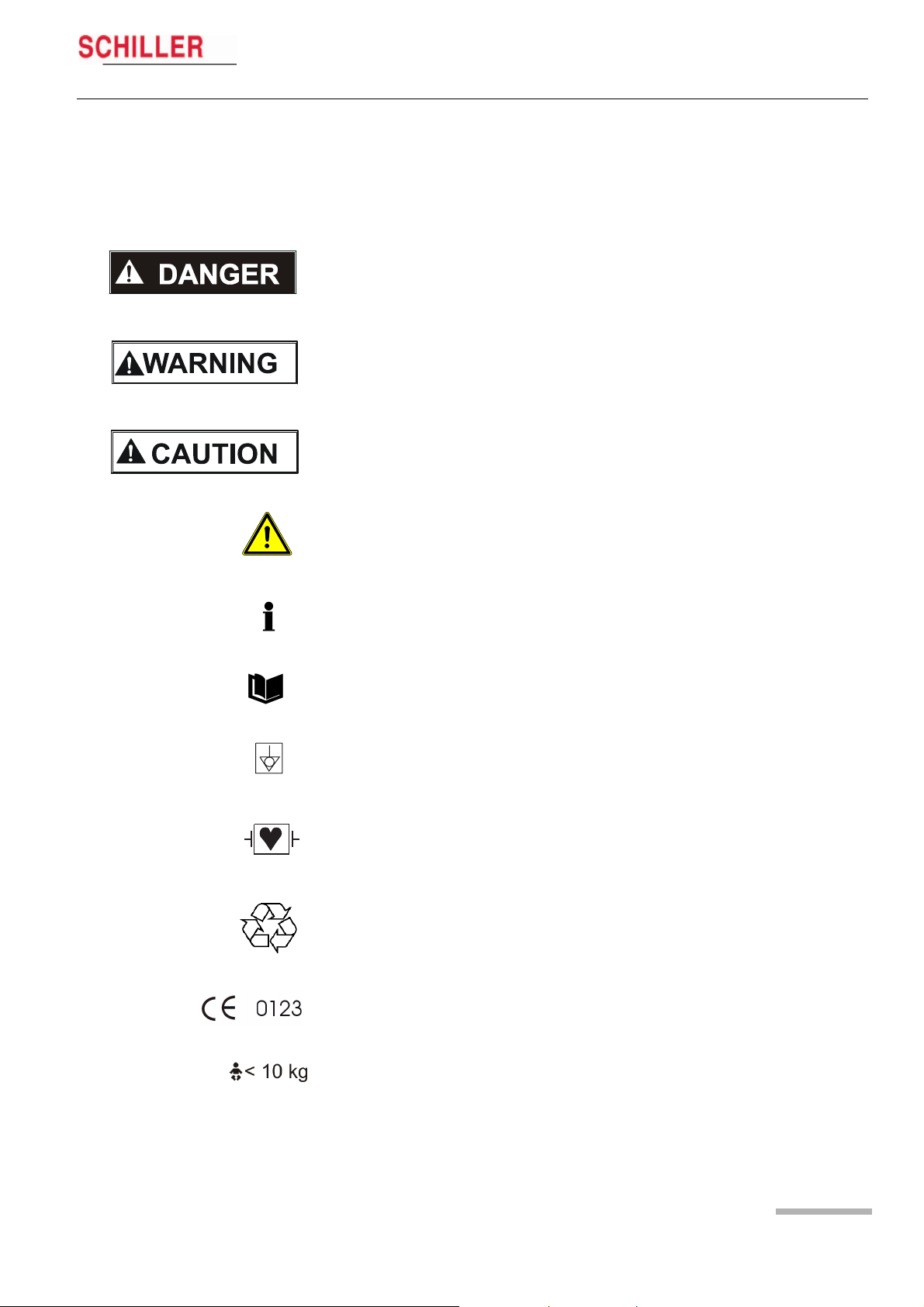
1.8 Safety Symbols and Pictograms
The safety level is classified according ANSI Z535.4. The following overview shows
the safety symbols and pictograms used in this handbook.
For a direct danger which could lead to severe personal injury or to death.
For a possibly dangerous situation, which could lead to bodily injury or to death.
For a possibly dangerous situation which could lead to personal injury. This symbol is
also used to indicate possible damage to property.
For general safety notes as listed in this chapter. When this symbol is displayed on the
unit, it means that the user should refer to the user guide.
Note for possible dangerous situations which could lead to damage to property or system failure. Important or helpful user information.
Reference to other guidelines.
Potential equalization.
CF symbol. This unit is classified safe for direct cardiac application. Only defibrillation
protected when used with the original SCHILLER patient cable.
The unit/component can be recycled.
Art. no.: 2.510492 rev.: b
Notified body of the CE certification (TÜV P.S.).
Is intended for infants weighing less then 10 kg.
Page 7
2 Introduction
2.1 MT-101/200 Range of Application
2 Introduction
2.1 MT-101/200 Range of Application
The MICROVIT MT-101 Holter is designed to record long-term electrocardiograms for
the diagnosis of symptomatic and asymptomatic arrhythmias, i.e. bradycardia and
tachycardia, and for patients after resuscitation or suffering from diseases such as
cardiomyopathy, high blood pressure or long QT syndrome.
The recording can also be used to help examine palpitations or syncopes and
dizziness, to verify medical therapies, and to carry out subsequent treatments after a
bypass operation or a PTCA. The ST segment analysis of an ECG recording allows
the detection of a symptomatic or asymptomatic ischemia.
MT-101/MT-200
The SCHILLER Holter system comprises two main parts. The MT-101 Holter recorder
and the MT-200 program. Recordings made by the MT-101 unit are downloaded to
the MT-200 for display, storage and analysis.
o
S
R
E
L
L
I
H
C
S
r
o
f
s
t
h
g
i
r
y
t
r
e
p
o
r
p
l
a
i
c
r
e
m
m
o
c
d
n
a
l
a
i
r
t
s
u
d
n
i
l
l
A
.
s
e
m
a
N
e
SDS-200 2.01
d
a
r
T
SDS-104 2.01
d
n
SEMA-200 1.81
a
s
k
SEMA-COMM 1.80
r
a
M
MT-190/200 1.80
e
d
MS-3 2.03
a
r
T
BR-102 2.40
d
e
r
Demo Sema-200
e
t
s
i
Demo MT-200
g
e
r
System Software
e
r
Release Notes
Ea
P
Acrobat Reader 4.0
O
C
S
I
N
I
M
d
n
a
A
For further information please visit our homepage
M
E
S
,
www.schiller.chor send an e-mail to sales@schiller.ch
S
U
G
R
A
,
T
I
V
O
N
O
S
,
T
I
V
O
R
C
I
M
,
T
I
V
O
R
I
P
S
,
T
I
V
O
I
SCHILLER
SWITZERLAND
D
R
A
C
,
R
E
L
L
I
H
C
S
t
f
w
a
r
e
s
.
o
n
t
h
i
s
C
e
h
o
l
d
e
r
D
b
e
l
o
n
g
t
o
S
C
H
I
L
Part No. 2.100256
g
t
o
t
h
e
i
r
r
e
s
p
e
c
t
i
v
LE
R
A
G
,
S
w
i
t
z
e
r
l
a
n
Version x.xx
d
e
n
a
m
e
s
b
e
l
o
n
Good signal quality is vital for the success of a recording. The built-in Holter display,
enables the ECG signal quality to be checked before starting, and the recording
commenced directly from the device. This gives a high degree of reliability.
At the end of a recording, the data is transferred from the Holter recorder to a PC. The
transfer of a recording typically only requires a few minutes.
d
.
A
l
l
r
i
g
h
t
s
r
e
s
e
r
v
e
d
.
Ó
S
C
H
I
L
L
E
R
A
G
,
C
H
6
3
4
1
B
a
a
r
,
S
w
i
t
z
e
r
l
a
n
d
.
A
l
l
o
t
h
e
r
s
t
a
t
e
m
e
n
t
s
a
n
d
t
r
a
The MT-200 is a PC based ECG evaluation program. An ECG is recorded using the
SCHILLER MICROVIT MT-101 Holter. Two or 3-channel ECG recordings can be
recorded over a period up to 72 hours. After the transfer of the recording data into the
MT-200 program, the data can be displayed, saved, analysed and printed. The MT200 program enables quick access to the recording data and displays the ECG and
analysis data in a logical and understandable way for diagnosis.
Page 8

MT-101/MT-200
User Guide MT-101/200 Range of Application 2.1
The MT-200 includes analysis of the following:
Supraventricular Arrhythmias • supraventricular extrasystoles
• couplets
• triplets
• chain of four or more SVES
• (SV tach)
•bigeminy
• trigeminy
Sinus Rhythm Alterations •tachycardia
• bradycardia
• pause
• abs. arrhythmias
Ventricular Arrhythmias • ventricular extrasystoles
• couplets (VES chain)
• triplets
• chain of four or more VES
• (V tach)
•bigeminy
• trigeminy
•R on T
Introduction 2
Heart Rate Trend • calculated over 4, 8 or 16 beats and
• averaged over 1 to 10 minutes
ST Trend • setting of the distance from J-point for ST measurement (J-point + 10 to 100 ms)
• episodes detected separately for channel 1, and/or channel 2, and/or channel 3
when ST level is exceeded (1 to 3 mm)
Pacemaker • 6 pacemaker templates
• heart rate variability
• tachograms and tabular presentation after analysis of the recording
Art. no.: 2.510492 rev.: b
Page 9
2 Introduction
2.2 MT-101 Components and Operation
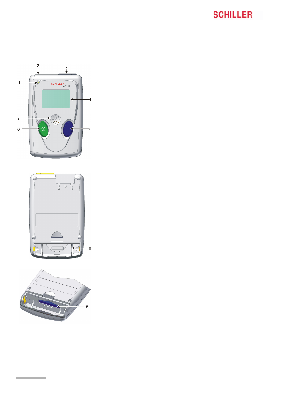
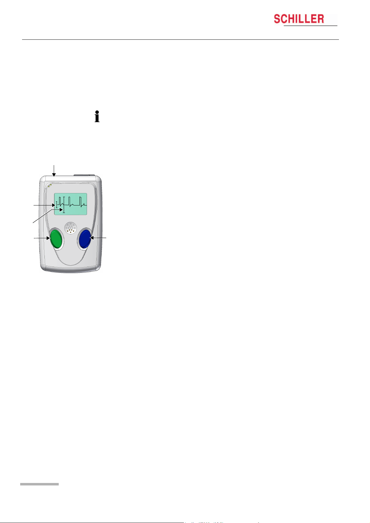
2.2 MT-101 Components and Operation
Front
(1) Microphone for patient identification
(2) Patient cable connection
(3) USB-cable connection
(4) LCD display
(5) Programming button
(6) On/off and programming button
(7) Loudspeaker
Back
(8) Battery housing
(9) SD memory card
Programming
The MT-101 Holter can be programmed simply using the two keys following the menu
guidance on the LCD display.
MT-101/MT-200
Data transmission
The ECG data transmission to the PC can be realised in two ways:
– directly via standard USB connection (3)
– by removing the memory card (9) from the battery housing and transmitting the
data to the PC by means of a memory card reader. The advantage resulting from
this procedure is that the Holter can be equipped with a new memory card and
is immediately available for the next patient.
Page 10
MT-101/MT-200
Introduction 2
User Guide Operating and Display Elements 2.3
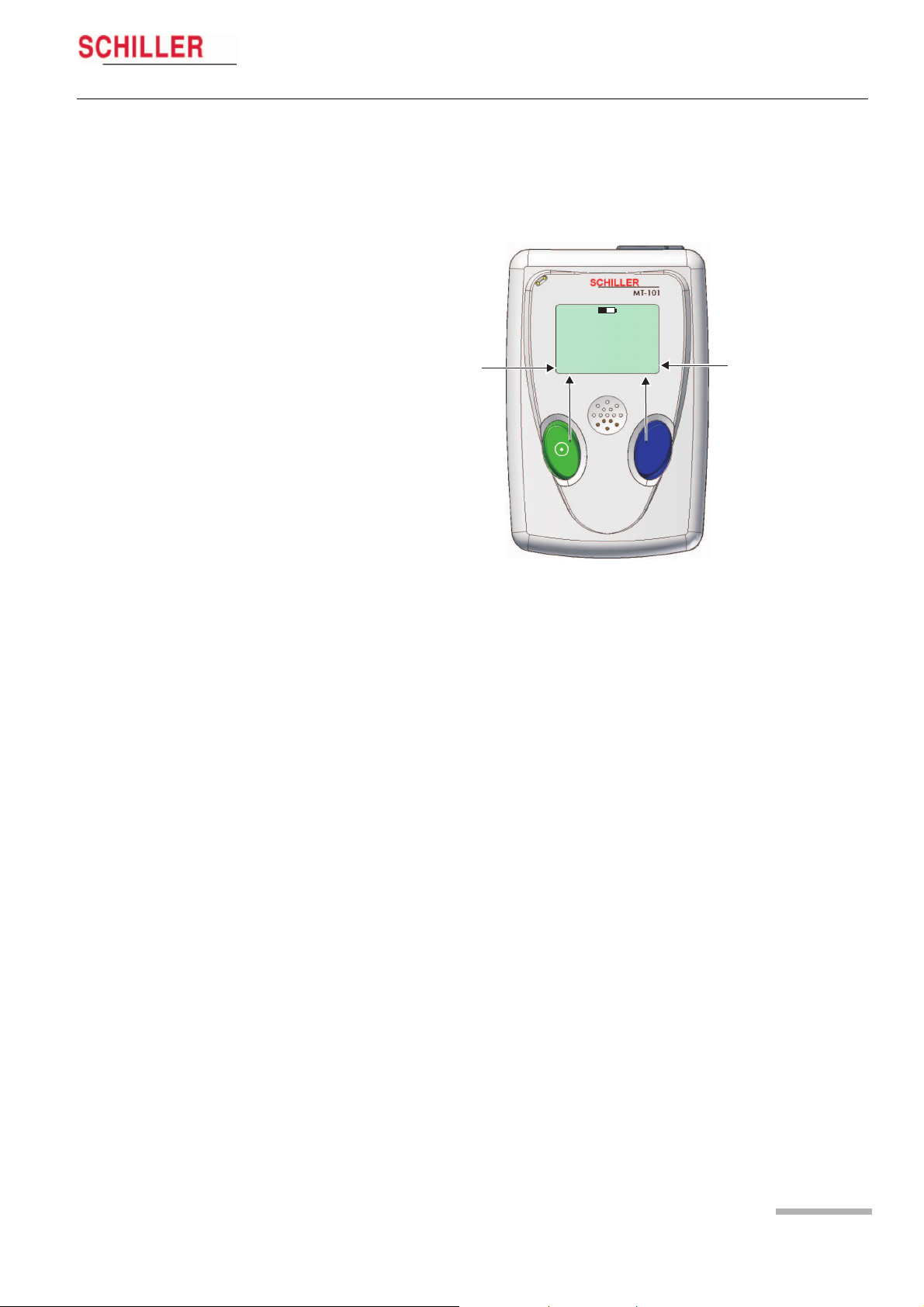
2.3 Operating and Display Elements
The Microvit MT-101 is operated with the two buttons and the menu guidance on the
LCD. The green key with the switching-on symbol is used additionally to switch the
device on and off.
Functions
green button:
On/off
NEXT
EVENT
SPEED 1x — 3x
NO
2.3.1 Switching on
Press the green button. The display shows the name and version number of the device before the main menu is displayed.
2.3.2 Switching off
Keep the green button pressed for five seconds. When the button is released, the device is switched off. If an ECG recording is running, first stop it following the same procedure.
If no recording is running, the device will be switched off automatically after five minutes.
Status
NEXT OK
15:45
Functions of the
blue button:
OK
CHANGE
EVENT
YES
CHANN2/3
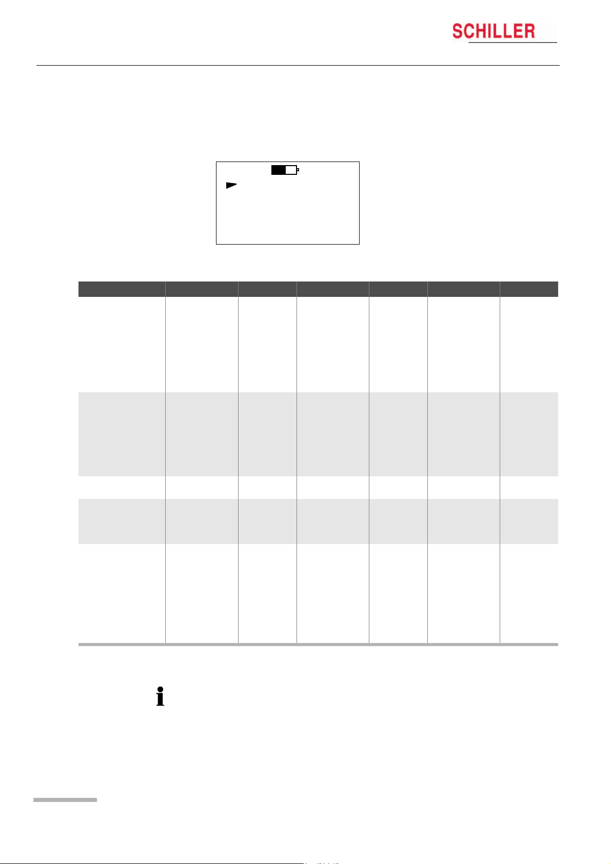
2.3.3 Battery display
The battery symbol indicates the battery’s load status. If the battery is full, the symbol
is solid — also see para. 2.5.2 Inserting/changing the battery, page 13.
2.3.4 Status display
The operating status is displayed in the left upper corner of the LCD. REC for record-
Art. no.: 2.510492 rev.: b
ing, USB if the MT-101 is connected to a PC, USB* for data transmission to a PC.
Page 11
2 Introduction
2.4 MT-101 Menu Structure
Main Menu Sub-Menu 1 Value/Info Sub-Menu 2 Value/Info Sub-Menu 3 Value/Info
RECORD START ECG Signal Chan1 speed x1, x2 or x3
ECG Signal Chan2 speed x1, x2 or x3
ECG Signal Chan3 speed x1, x2 or x3
Start record? Yes/No
ECG-recording start-
ed!
RECORD SETUP
LAST RECORD Patient ID*
SYSTEM INFO SerNo.
SYSTEM SETUP Contrast 1…8
Patient ID > Voice-record
PM Det.* On/off
Duration 24, 48, 72
Sampling 125 Hz
Events* > Events
Language ENG …
Bat
Date/time > Year 2000….2099
2.4 MT-101 Menu Structure
The menus are selected with the green button (NEXT). A selected menu is opened
with the blue button. Depending on the called menu, the button functions may
change.)
MAIN 15:45
RECORD START
RECORD SETUP
LAST RECORD
SYSTEM INFO
SYSTEM SETUP
NEXT OK
2.4.1 Menu Overview
Ye s > Event button Event saved!
> Record info
> Stop recording?
> Play ID
Version
Bat Type
SD-Card
Alkaline
NiMH2100
> Month 01….12
> Day 01….31
> Hour 00.23
> Minute 00….59
ECG recording
stopped
>
Stop Stop Recording
>
MT-101/MT-200
Main
Start Start Recording
Stop Stop Playing
Page 12
* To record pacemaker pulses it is important that ‘PM Det‘ is set to on — see para. 5.1.1
Pacemaker, page 21.
MT-101/MT-200
Introduction 2
User Guide Initial Operation 2.5
2.5 Initial Operation
2.5.1 Unpacking
Check that all ordered items are present and free of shipping damage. Immediately
report any damage to SCHILLER AG.
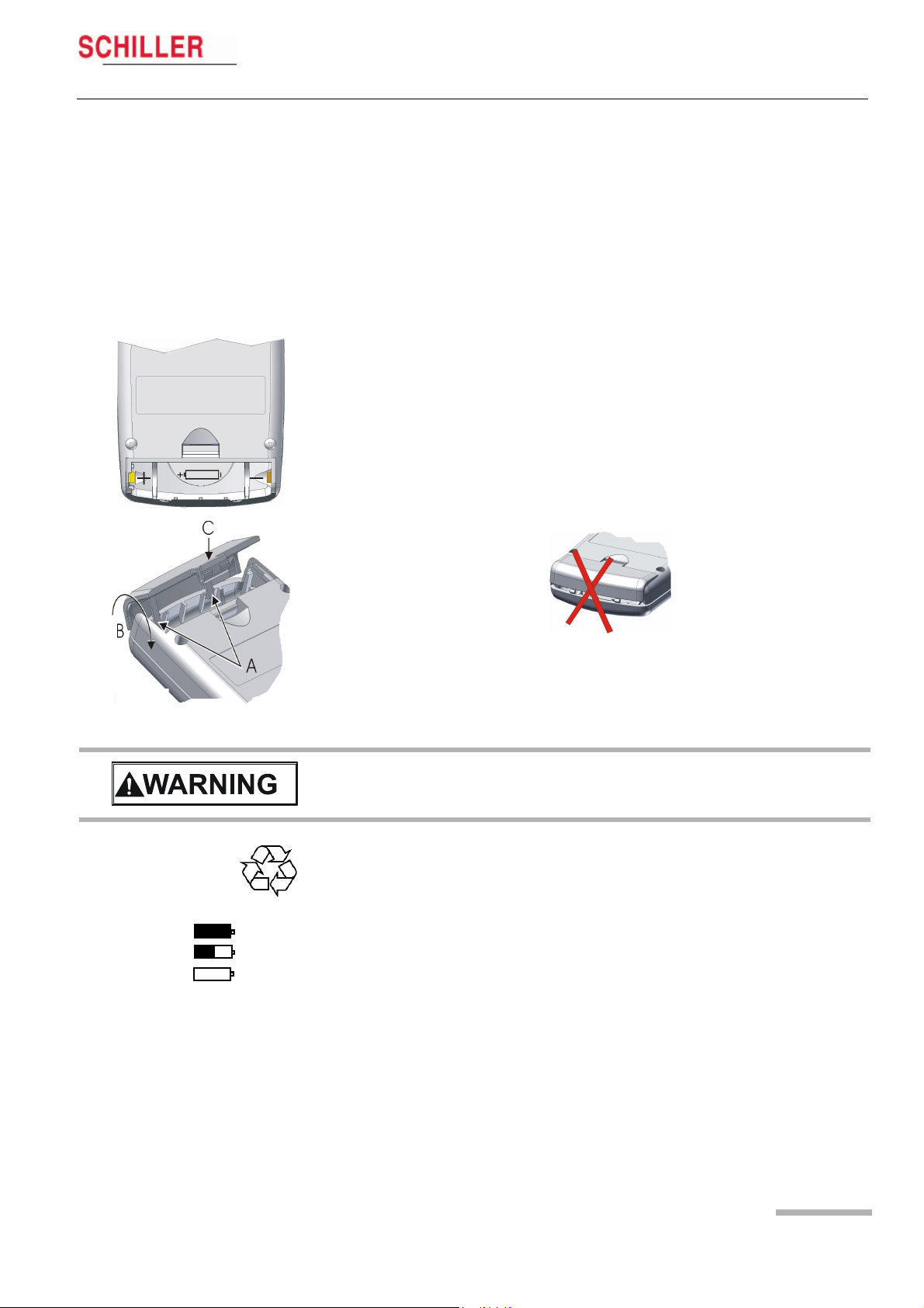
2.5.2 Inserting/changing the battery
Open the battery compartment and insert the supplied battery or accumulator. Observe the polarity!
Note
The delivered battery is of alkaline type AA/LR6. If you use an NiMH 2100 mAh accumulator, make sure that BAT NiHM is selected in the SYSTEM SETUP menu. If the
wrong type is selected, the battery capacity will not be displayed correctly.
On closing the battery cover, pay attention that the two lugs (A) are inserted correctly.
The cover is closed in the direction indicated by the arrow (B). In order to engage the
cover, press it down (at position C) until it clicks in place.
V Attention — danger of explosion Do not dispose of batteries by fire or incinera-
tor.
V Attention — danger of acid burn Do not open the battery casing.
Only dispose of batteries in official recycling centres or municipally approved areas.
Switch on the device and check the battery charge capacity. The battery symbol must
Full
Half full
Empty
Art. no.: 2.510492 rev.: b
be fully black. This corresponds to a maximum recording time of 24 hours.
An audible and visual indication is given during recording when battery capacity is
limited. The time will vary according to the type of battery installed (alkaline or
NiMH2100) — but is normally between 1 and 2 hours. When the alarm is given and
recording is to be continued, we recommend that the battery is replaced at the first
opportunity — see para. 2.5.2 Inserting/changing the battery, page 13
When recording is stopped because of low battery capacity, and the battery is
replaced within 5 hours of the unit switching off, the recording will continue — see para.
3.2.1 During the Recording and Patient Information, page 17.
Page 13
3 Preparing a Holter Recording
3.1 Position of the Electrodes
3 Preparing a Holter
3.1 Position of the Electrodes
MT-101/MT-200
Recording
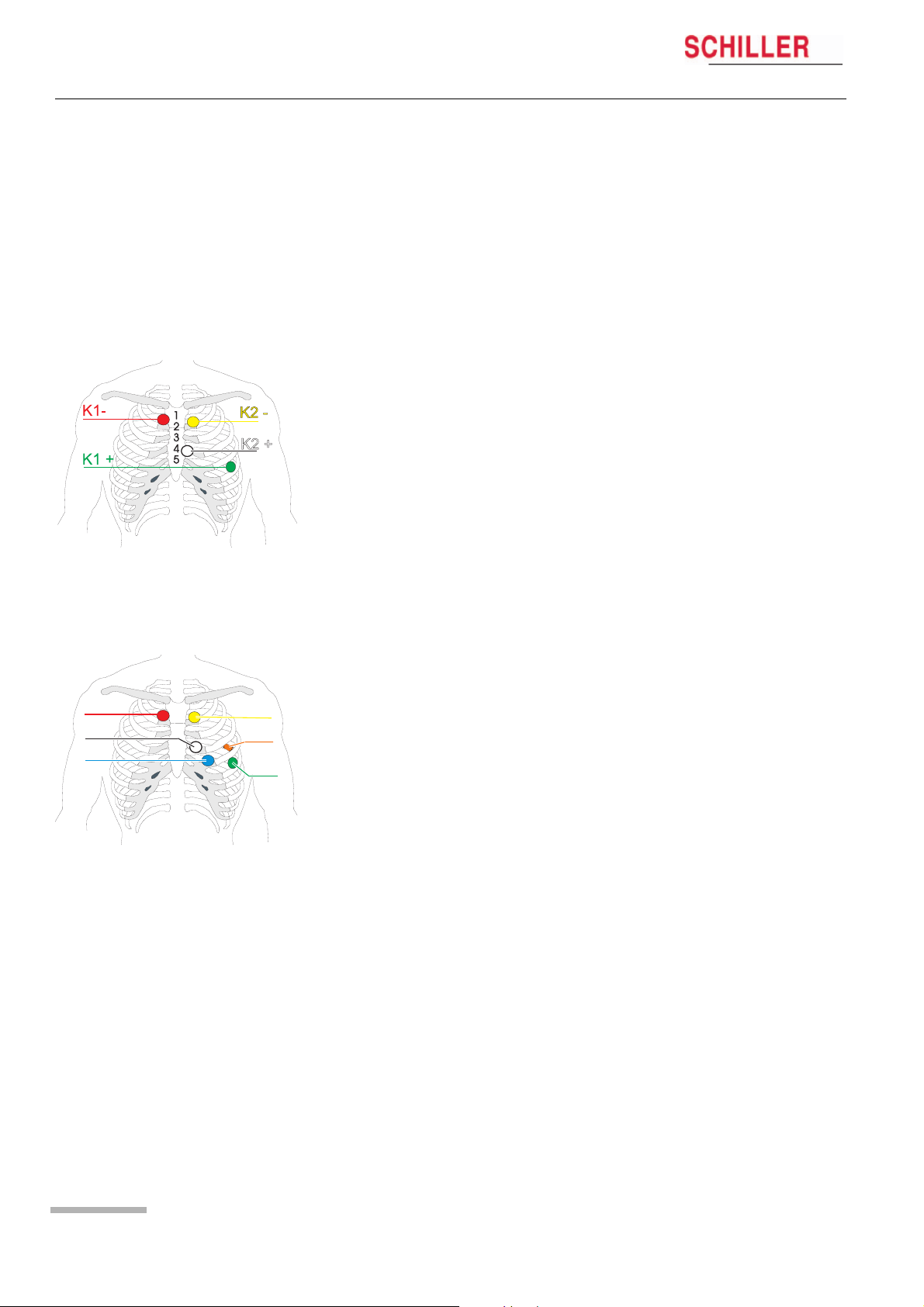
Typical electrode position for a 4-lead cable (2-channel recording)
The recommended electrode placement for a 2-channel recording is shown below.
Channel 1 positive (K1+) = green
Channel 1 negative (K1-) = red
Channel 2 positive (K2+) = white
Channel 2 negative (K2-) = yellow
K1-
K2 +
K3 —
Typical electrode placement for a 6-lead cable (3-channel recording)
The recommended electrode placement for a 3-channel recording is shown below.
Channel 1 positive (K1+) = green
1
2
3
4
5
K2 —
K3 +
K1 +
Channel 1 negative (K1-) = red
Channel 2 positive (K2+) = white
Channel 2 negative (K2-) = yellow
Channel 3 positive (K3+) = orange (positioned on the patient’s back)
Channel 3 negative (K3-) = blue
Page 14
MT-101/MT-200
Preparing a Holter Recording 3
User Guide Position of the Electrodes 3.1
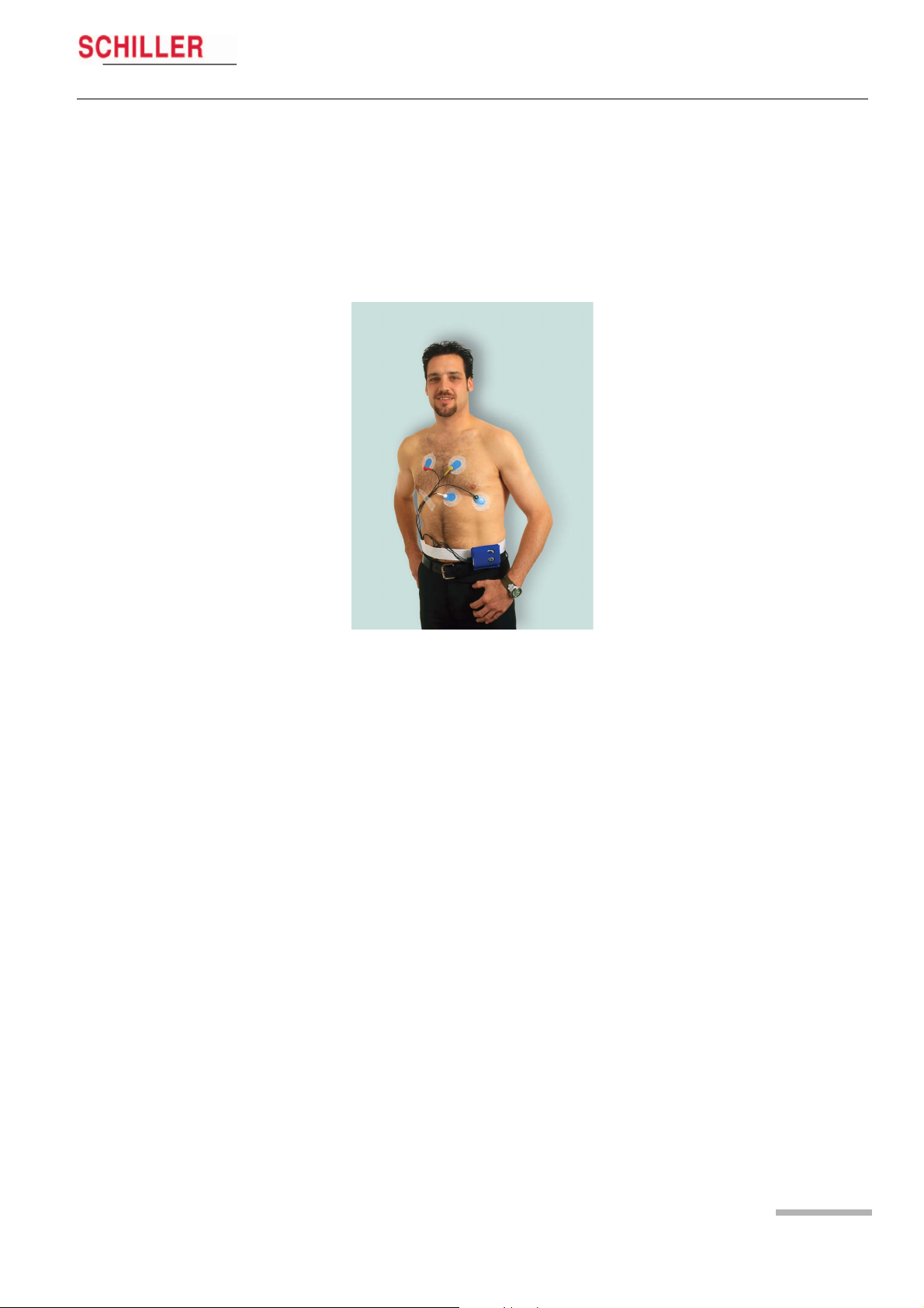
Electrode Placement
Form a stress loop in every cable and secure them with adhesive strips to relieve the
electrodes (strain relief). In order to ensure good data evaluation, the ECG amplitudes
should be examined in the sitting, lying and standing position of the patient.
Holter ECGs use a bipolar lead system (one positive and one negative lead) for each
channel. Channel 1 approximates to modified lead V
modified lead V
and channel 3 approximates to modified lead V3.
2
, channel 2 approximates to
5
Channel 1 Place the RED negative electrode under the clavicle on the right Sternal margin.
Place the GREEN positive electrode in the fifth left intercostal space on the anterior
axillary line (position approximately equates to V
).
5
Channel 2 Place the YELLOW negative electrode under the clavicle on the left sternal margin.
Place the WHITE positive electrode in the fourth left intercostal space on the anterior
axillary line (position approximately equates to V
).
2
Channel 3 Place the BLUE negative electrode in the fourth left intercostal space near the ster-
num.
Place the ORANGE positive electrode on the back in the fifth left intercostal space,
between the spine and the scapula (position approximately equates to V
).
3
• The above electrode placement is suggested; other electrode configurations are
possible.
• Ensure that the QRS complex is bigger than the T wave.
• Ensure that the trace is larger than 1mV. See 1mV reference (4) on following page.
Art. no.: 2.510492 rev.: b
• To avoid artifacts in women patients, the red and white electrodes can be placed
lower if necessary.
Page 15
3 Preparing a Holter Recording
3.2 Commencing a Holter Recording
3.2 Commencing a Holter Recording
3
ECG
4
SPEED x1
5
1
2
MT-101/MT-200
The ECG recording can be started without the MT-200 PC software. The most important data can be entered in the MT-101 directly, and the ECG signal examined directly
on the LCD.
A recording can also be started from the MT-200 program where all channels can be
viewed simultaneously before commencing — see para. 5.1 Starting a Recording from
the MT-200 Program, page 19.
Preparing the patient
1. Attach electrodes to patient.
Setting up the Holter MT-101
2. Press button (1) to switch on MT-101. Check battery charge capacity. If the symbol is only half filled out, change battery.
3. Choose NEXT (1) to select RECORD SETUP menu to make recording settings:
– Patient ID — record patient ID using the microphone and playback facility
– Select Pacemaker detection on or off — see para. 5.1.1 Pacemaker, page 21
– Define period of recording — 24, 48 or 72 hours
Checking the ECG signal
4. Connect patient cable to MT-101 (3).
5. Confirm RECORD START menu with “OK” (2) and check ECG signal Channel 1.
Press CHAN2/3 to select and check channel 2/3. Press “OK” (2) to access
START RECORDING panel.
The signal’s max. amplitude corresponds to the height of the moving line (5). The 1mV
amplitude reference is the vertical line on the left (4). Ensure the signal amplitude is
greater than 1mV.
Starting an ECG recording
6. Confirm the start of the recording with YES (2).
Stopping the ECG recording
7. Press and hold button (1) for 5 seconds. You will be prompted if you wish to stop
the recording. Confirm with YES (2).
NOTE: If no confirmation is received to cease recording (button (2) pressed), within
15 seconds, the unit returns to recording mode.
Page 16
Switching off the MT-101
8. If the unit is recording, first stop the recording step (7).
9. Ensure the main menu is displayed and that the cursor is at the RECORD START
position.
10. Press and hold button (1) for 5 seconds to switch the device off.
MT-101/MT-200
Preparing a Holter Recording 3
User Guide Taking an Extended Recording (Longer than 24 hours) 3.3
3.2.1 During the Recording and Patient Information
Inform the patient about the use of the MT-101.
Event record
• Every event should be entered in the diary, together with the time, the activities at
the time of occurrence and the symptoms.
• Instruct the patient to press the EVENT button at any time during the recording to
register an event as follows:
1. Press button (1 or 2).
2. Record event in the patient diary.
Note:
The template for the patient diary is stored on the software CD as Word or pdf file. An
example is given at the end of the book — see para. 13 Patient Diary, page 89.
No ECG signal or lead-off
1. Check cable connection on device.
2. Check cable connection on electrodes.
3. Re-attach electrodes to body.
General information
The device is not waterproof. The patient should be advised not to take a bath or
shower during the recording.
Battery replacement during the recording.
Change battery when an audible indication is given and the message ‘BATTERY LOW
— change battery’ is displayed the MT-101. — this will occur approximately 1-2 hours
before switch off (dependent on battery type). Proceed as follows:
RE C 8 :56
ECG recording
(00:02)
1 2
1. Press EVENT button (1 or 2) and make an entry in your diary.
– DO NOT SWITCH THE DEVICE OFF
2. Open battery compartment and replace battery with a new one of the same type.
Observe correct polarity, and replace battery cover — see para. 2.5.2 Inserting/
changing the battery, page 13.
3. Switch the device on by pressing button (1). After a few seconds the message
‘ECG recording restart’ is displayed while the unit re-initialises. This is followed by
the message ‘ECG recording’ and ECG recording automatically resumes.
When a recording is stopped (because of low battery capacity or because of
battery removal), the battery must be replaced within 5 hours of the unit
switching off for the recording to continue.
3.3 Taking an Extended Recording (Longer than
24 hours)
The MT-101 can record up to 72 hours of Holter data if required. To make a recording
Art. no.: 2.510492 rev.: b
longer than 24 hours, the battery in the MT-101 must be changed as detailed above.
An audible alarm and visual indication will be given when the battery must be
changed.
Page 17
4 Transferring a Recording to the PC
4.1 Data Transmission to PC from MT-101
4 Transferring a Recording
to the PC
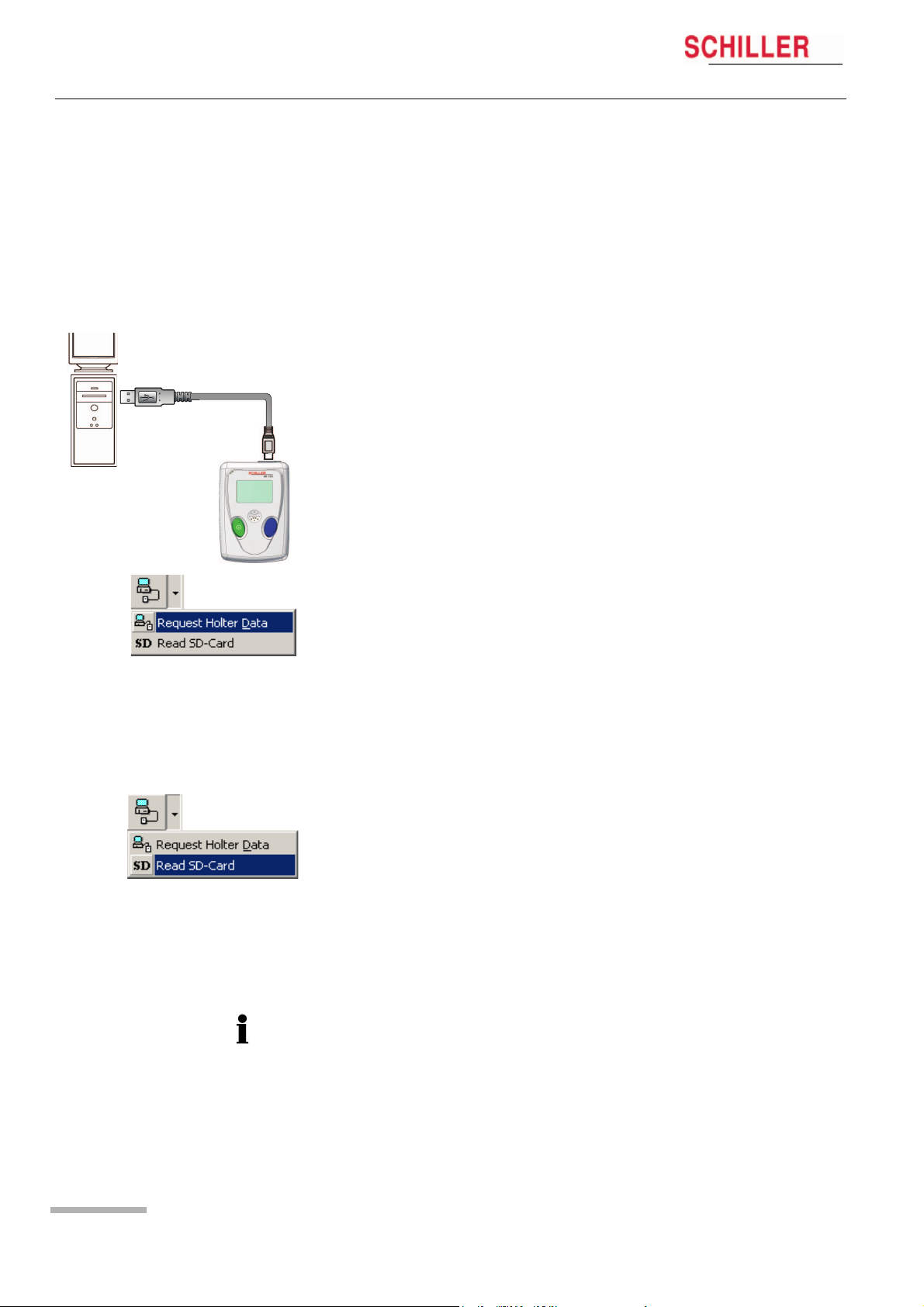
4.1 Data Transmission to PC from MT-101
1. Connect the USB cable between the MT-101 and PC (see picture below — the rubber cover on the MT-101 must be removed — the message «MT-101 connected to
PC» appears.
2. Start MT-200 software on PC.
3. Click on the data transfer icon and select «Request Holter Data». The dialogue box
shows the transferred data in per cent.
The data is stored automatically. If no patient data is entered, the file will be saved with
the date and time.
MT-101/MT-200
4.2 Data transmission to PC with Memory Card
Reader
1. Connect the card reader to the USB. The memory card reader appears as a physical drive on your desktop.
2. The path name for this drive must be entered in the menu Option/System/Path/
SD-Card path — see para. 8.5.3 Directories, page 76.
3. Insert the memory card in the card reader or PCMCIA adapter.
4. Execute the function “Read SD-Card”. The data is read into the indicated path (for
path location see point 2)
Data can also be imported from an SD card — see para. 7.2.3 Importing recordings,
page 65
Page 18
MT-101/MT-200
Displaying an ECG Signal 5
User Guide Starting a Recording from the MT-200 Program 5.1
5 Displaying an ECG
Signal
5.1 Starting a Recording from the MT-200
Program
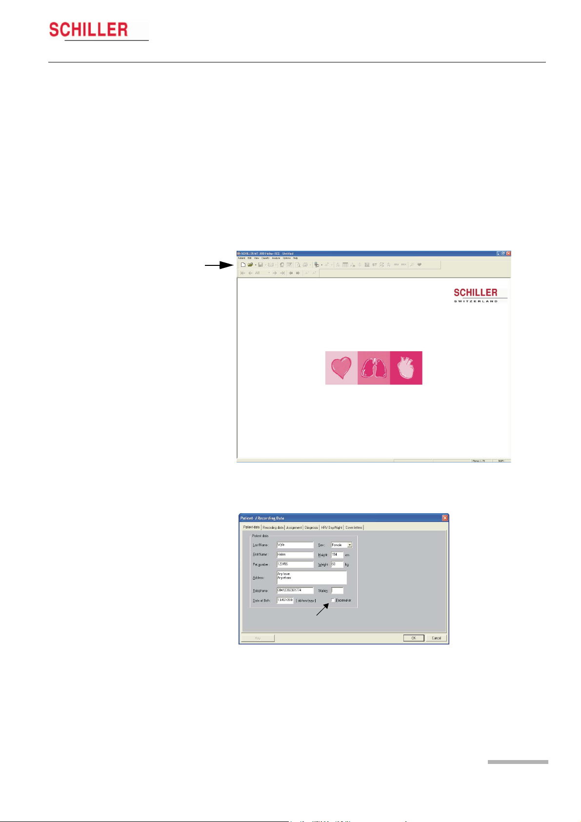
1. Start the MT-200 program on your PC /CS-200. The welcome page is displayed.
1
2. Click on the “New recording” icon (1). The patient data screen is displayed:
Art. no.: 2.510492 rev.: b
3. Enter the patient data and confirm with the «OK» button. To enter the data, click
with the mouse cursor into the fields or jump from entry field to entry field using
the tab key.
4. If pacemaker detection is required check the pacemaker box (1) — see para. 5.1.1
Pacemaker, page 21 for notes on pacemaker detection
1
Page 19
5 Displaying an ECG Signal
5.1 Starting a Recording from the MT-200 Program
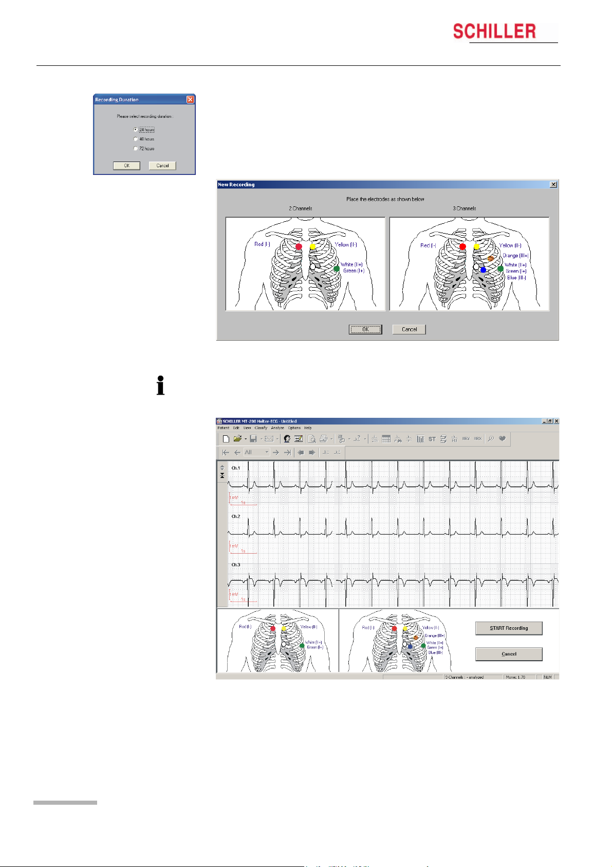
5. When the patient data has been entered and Ok is clicked, enter the duration of
the recording
Note: The data displayed or entered on the other pages of patient information selected by clicking on the tabs at the top of this window (Recording data, Assignment
etc.) — are only available after a recording has been made.
6. Place the electrodes as indicated in the dialogue box.
MT-101/MT-200
If a 4-lead patient cable was used for the Holter recording, only two channels will be
displayed in the MT-200.
Page 20
7. Check the signal and re-apply the electrodes if necessary.

MT-101/MT-200
Displaying an ECG Signal 5
User Guide Starting a Recording from the MT-200 Program 5.1
8. Click on START RECORDING to commence the recording. The dialogue box re-
minds you to check the battery load capacity.
The recording has now commenced. The LCD of the MT-101 indicates that ECG recording has been started.
Remove the USB from the MT-101 Holter recorder and close the connector again with
the protective cover.
5.1.1 Pacemaker
The MT-200 cannot determine pacemaker spikes itself and it is not possible to detect
pacemaker signals by later analysing the recording in the program if the pacemaker
detection function was not enabled during the original recording. So that the MT-200
can detect pacemaker spikes, pacemaker detection must be activated before the start
of the recording.
Activating Pacemaker Detection
Pacemaker detection can be activated in either the MT-200 program or the MT-101:
« If the recording is started from the MT-200 program, then pacemaker activation
can be carried out in the MT-200 by ticking the pacemaker box in the patient data
window — see para. 5 Displaying an ECG Signal, page 19.
« If the recording is started from the MT-101 itself, then pacemaker activation must
be carried out in the MT-101 menu > RECORD SETUP > PM Detection > ON, see para. 2.4.1 Menu Overview, page 12.
«
Detection and Recording of Pacemaker Spikes
The MT-101 only detects pacemaker signals in long-term ECG recordings when the
slopes and amplitudes of the signal exceed the preset limits and when pacemaker
detection is enabled. As the MT-101 uses a sampling frequency of 500 Hz for a
recording (i.e. a digitalisation interval of 2 ms), complete digital processing is
impossible due to the short duration of some pacemaker signals (less than 1 ms).
Therefore, analogue processing of the ECG signals is applied by the MT-101 for
pacemaker detection.
Analogue Pacemaker Detection in Channel 1
Analogue pacemaker detection is confined to the first channel of the MT-101. It is
therefore optimal when the amplitude of the pacemaker signal for the first ECG channel is greater than that for the second channel. In some instances, this is not the case.
In this case, it is recommended that the real-time ECG traces are viewed on the
screen before starting the long-term recording. Pacemaker detection is automatically
enabled on the real-time display. The pacemaker signals, however, are not always
detected. If this is the case and the amplitude of the pulse is greater in the second
channel, simply exchange the electrodes of channels 1 and 2. After the real-time display, pacemaker detection must be enabled for long-term recording in the MT-200!
Evaluation and Display of Pacemaker Spikes in the MT-200
Art. no.: 2.510492 rev.: b
Program
Pacemaker signals are marked in the MT-200 program by vertical lines in the ECG
after evaluation of the recording. Note that these lines are correctly positioned in relation to time but are not proportional in either amplitude (voltage) or duration of the
pacemaker pulse, nor do they indicate the polarity. The pacemaker representation is
always positive but the actual pacemaker spike may be positive or negative.
Page 21
5 Displaying an ECG Signal
5.2 Transmission Problems
5.2 Transmission Problems
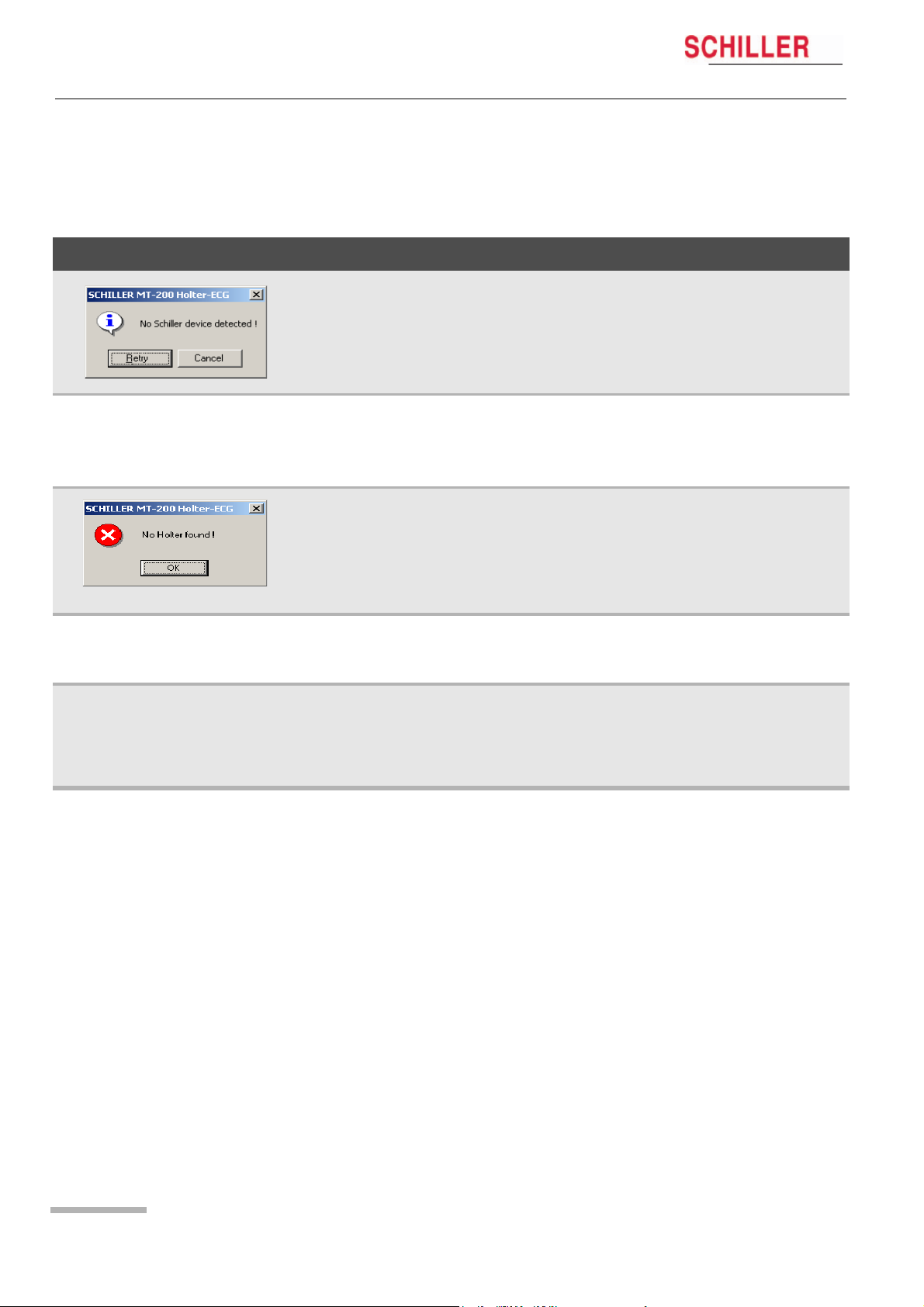
If an error message appears either before starting a recording or when attempting to
transfer a recording from the MT-101 to the PC, possible causes are as follows:
Error Cause Remedy
MT-101/MT-200
Communication Error (error
message displayed)
Display of DEMO VERSION
No error message. The program
cannot find the Holter.
• The USB cable assembly is not inserted
correctly in either the MT-101 or the PC.
• The SCHILLER USB driver has not been
installed
• The device is not connected.
• The SD memory card is not inserted.
• Unit not switched on
• Battery exhausted.
• Another device is connected to the USB. « Disconnect the device and connect the
• The hard-lock key is not present or incorrectly inserted.
• There is no license.
• With an USB installation, the program can
occasionally «hang» and not recognise
the USB connection.
« Check that both the cable connectors
are securely placed.
« Install USB driver (on SCHILLER soft-
ware CD.
« Connect the device.
« Check the memory card.
« Switch unit on
« Change batteries
MT-101.
« Check the hard-lock key on the PC.
« Contact SCHILLER for network license
1. Close the MT-200 program.
2. Disconnect the USB connector to your
PC. Wait circa three seconds and replace the connector.
3. Open the MT-200 program again.
Page 22
MT-101/MT-200
Displaying an ECG Signal 5
User Guide Transmission Problems 5.2
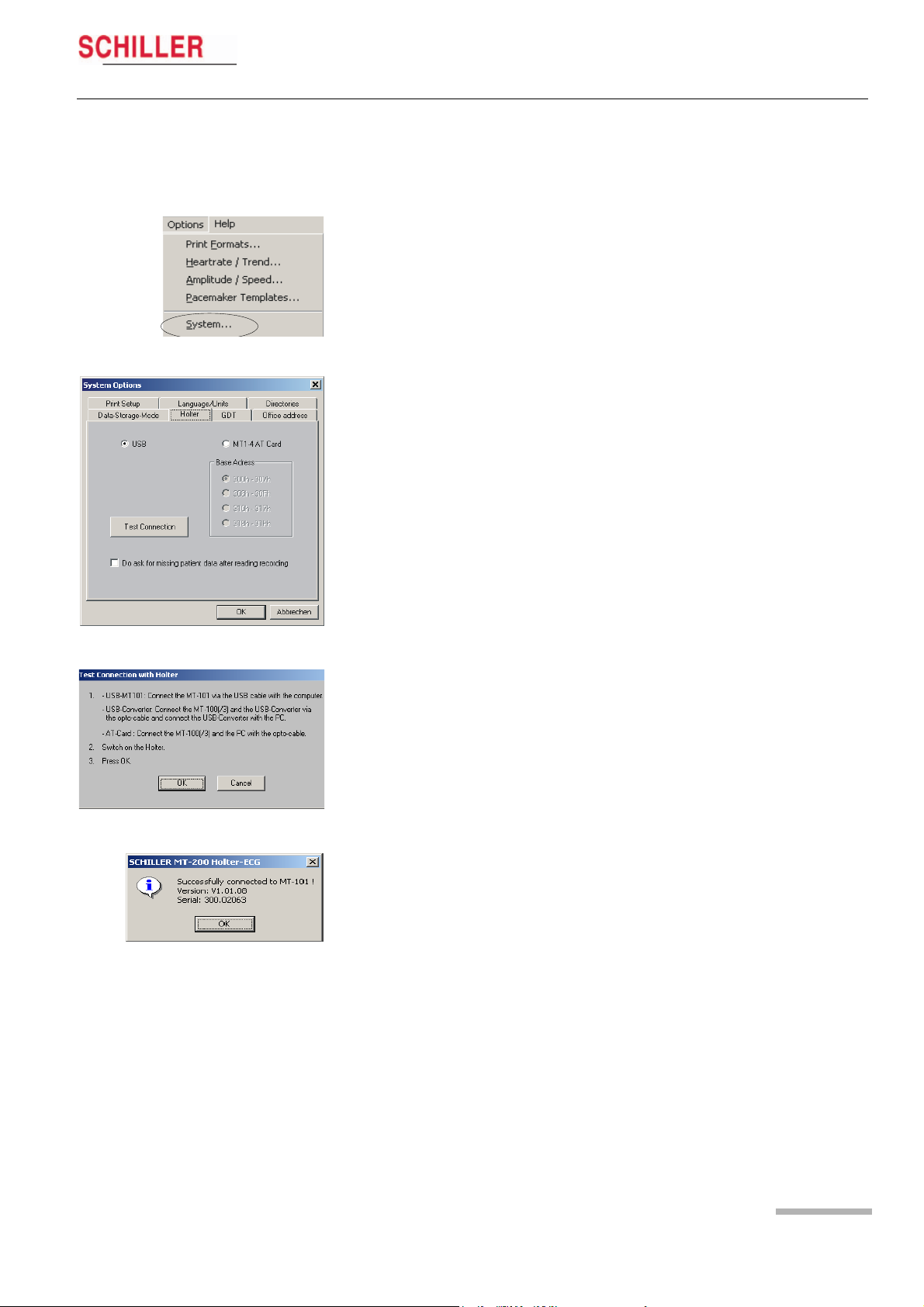
5.2.1 Checking the connection
A test function is available to check the integrity of the connection between the MT101 and the PC. To carry out the test function, proceed as follows:
1. In the «Options» menu, select «System».
2. Click the «Holter» tab.
3. Check the correct box for your installation (USB or AT card), and click the «Test
Connection» icon. Follow the instructions on the screen.
4. When «OK» is clicked, the software sends a test message to/from the MT-101.
5. A message box indicates the success of the transmission.
If the problem could not be solved, check all connections, ensure the MT-101 is
switched on, close the MT-200 application and restart the software.
Art. no.: 2.510492 rev.: b
Page 23
6 Viewing and Editing a Recording
6.1 Icons
6 Viewing and Editing a
6.1 Icons
MT-101/MT-200
Recording
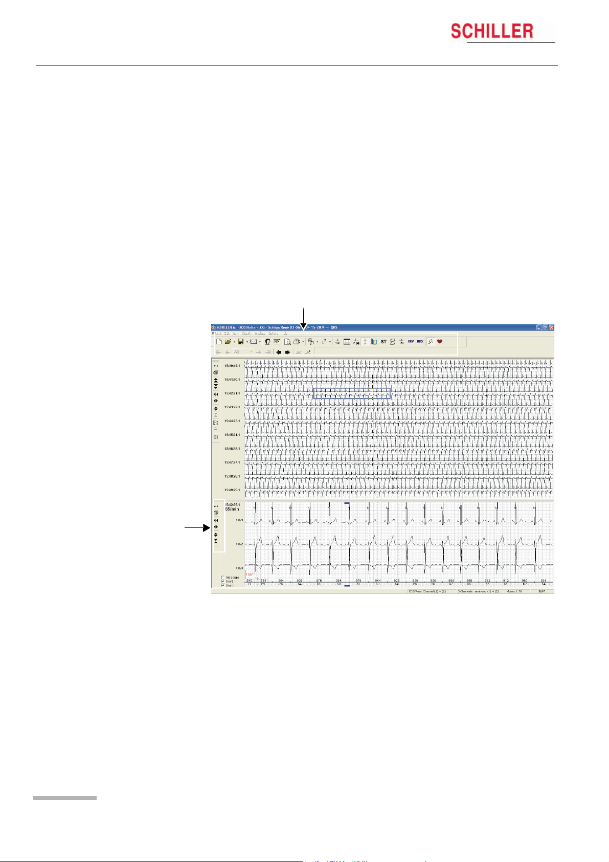
The MT-200 program gives different views for the presentation of a Holter recording.
Every view offers various data and analytical information. Besides display icons, the
toolbar contains additional function icons enabling the quick and easy activation of the
most frequently used functions. All icons can be activated any time and in any view.
In the ECG and zoom views, additional function icons are given to the left of the
screen to change the size of the traces and/or the time segment of the recording.
Function and View icons
Page 24
Function and View icons
in the ECG overview
All icons are selected by mouse-click (position the cursor on the icon and click with
the left mouse button).
When an icon is dimmed, it means that this function is not available for the currently
displayed screen and cannot be selected. For example, the zoom function is not
available in the ST view so the «Zoom» icon is dimmed. The patient name is always
displayed at the top of the page when an ECG recording is displayed.
MT-101/MT-200
Viewing and Editing a Recording 6
User Guide Icons 6.1
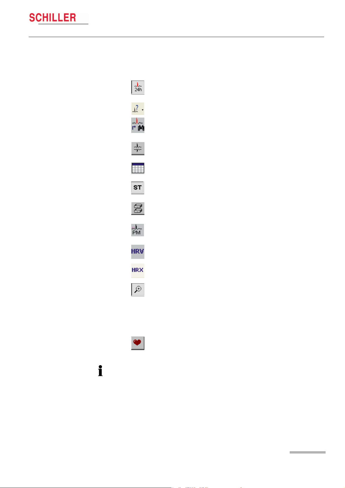
6.1.1 View icons
The function and view icons are only active (selectable) when a patient recording is
displayed. When an icon function cannot be selected, the icon is dimmed.
Event View* This gives an overview of all events in the 24 hour
period. Use this view to quickly identify and select
a specific time segment for display.
Analysis Summary View This provides a tabular overview of all important
measurements for the entire 24 hour period.
Event Samples View This allows three event samples from every event
category to be displayed, i.e. selected or replaced.
The user event samples can also be selected for
printing in this view.
ECG View* This zooms in on a specific time segment of ECG
for closer analysis. The next page can also be
displayed using the automatic scrolling function.
Analysis Summary This provides a Tabular overview of the recording.
ST Trend View (Option) This provides a graphical overview of the
ST trend with tabular measurements for ST
episodes.
Template View (Option) This provides a graphical overview of the
different types of averaged QRS waveforms with
classification, detected over the entire recording.
Pacemaker View (Option) This provides a graphical overview of
QRS templates measured in relation to the
pacemaker pulse.
Heart Rate Variability (Option) This provides a graphical overview of the
heart rate variability.
Heart Rate Trend This provides a graphical overview of the heart
rate trend. The maximum/minimum HR and NN
interval can be manually defined
Zoom View This gives a zoom view of a selected ECG
segment. Specific QRS complexes can also be
reclassified in this view. See «Reclassifying/Editing
a QRS complex» later in this section. The two leads
displayed in the zoom view are the two leads that
have been analysed. The display will always
contain two channels, even if only one channel has
been analysed.
HR Trend This displays the heart rate trend over the entire
recording.
Art. no.: 2.510492 rev.: b
If only one lead has been analysed, channel 1 is the second lead in the display. If
channel 1 has been analysed, channel 2 is the second lead displayed.
Options
All options are enabled with a programmed hard-lock key. This hard-lock key can be
obtained from SCHILLER AG.
*In event and ECG view modes, the lower part of the display is divided to give either
ECG zoom or heart rate trend.
Page 25
6 Viewing and Editing a Recording
6.1 Icons
6.1.2 Function icons
MT-101/MT-200
The following function icons are available when a patient recording is viewed:
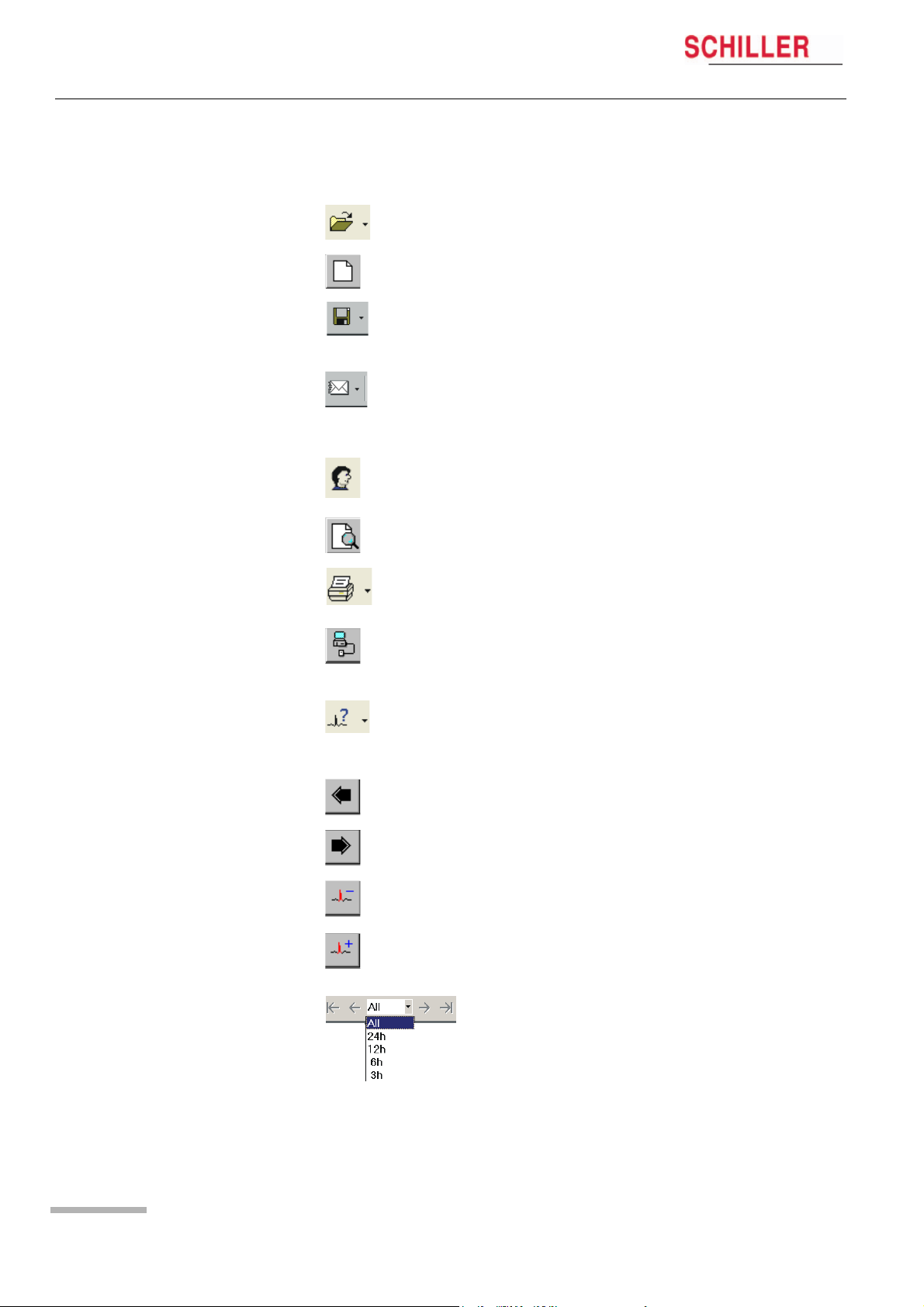
Open Recording Open a recording. Click the icon to list all available
files.Click the arrow to the right of the icon, to list
the last four opened recordings.
New Recording Enter the data of a new patient and start a new
recording.
Save Recording Save the current recording. Click the arrow to the
right of the icon, to display further options to save
as a pdf file. If saved as PDF file, it is possible to
delete the original if desired.
E-Mail Send the currently displayed recording by e-mail.
Click the arrow to the right of the icon, to give
further options to send as a pdf file. If “Send EMail
as PDF File” is selected, a pdf is generated and
automatically attached to the e-mail.
Patient and Recording
Data
Print Preview Select and display the pages to be printed (before
View / edit patient and recording data. View
analysis settings and diagnosis. General recording
settings and options.
printing)
Print Print (user defined) recording data. Click the arrow
to the right of the icon to select specific data for
print.
Request Holter Data Load data from the connected MT-101 Holter
recorder or via a memory card reader by selecting
«Read SD Card». In Win 95/98, a third function is
available to load data from a tape.
Analyse Click the Analyse icon to analyse the currently
displayed recording to the defined analysis
parameters. Click the arrow to the right of the icon
to analyse multiple recordings.
Scroll Back Scroll backwards (in time) of the zoom ECG
currently displayed.
Scroll Forward Scroll forwards (in time) of the zoom ECG currently
displayed.
Scroll Event Back Go to previous event.
Scroll Event Forward Go to next event.
Time Scale for View Display 3, 6, 12, 24 hours of analysed data or, for
recordings longer than 24 hours, all the data.
When 3, 6, 12, or 24 hour is selected, the arrow
icons at the side of the box, enable the user to
jump to the next time segment.
Page 26
MT-101/MT-200
Viewing and Editing a Recording 6
User Guide Icons 6.1
6.1.3 Tool icons in rhythm and zoom views
The tool icons are displayed in the rhythm and zoom views on the left hand side. Use
these icons to:
• decrease or increase the amplitude and speed
• move up or down a line and page
• immediately print a selected half hour segment of the recording
• change the channel (ECG view)
• select and analyse specific channels (ECG view)
• select a zoom section of the recording for printing
The page up/down and line up/down icons are not applicable and not displayed in the
zoom view
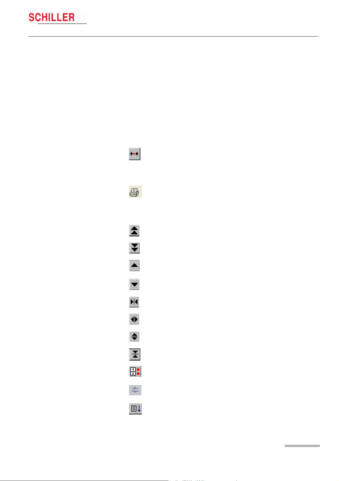
Centre In the ECG view, centres the selected (highlighted)
ECG section in the middle of the screen.
In the zoom view, positions the selected QRS
complex (cursor above and below QRS complex)
slightly to the left of centre in the zoom screen.
Print In the ECG view , immediately prints a 30 min.
segment of the recording (1/4 hour before and 1/4
after the selected section).
In the zoom view, marks the displayed zoom
section as «selected».
Page Up Moves to the previous page. Each page displays
between approximately 1 and 24 minutes of
Page Down Moves to the next page
Line Up Shifts the display up one line)
Line Down Shifts the display down one line
Decrease Speed Decreases the ECG scale (curves closer).
Increase Speed Increases the ECG scale (curves wider).
Increase Amplitude Curves bigger
Decrease Amplitude Curves smaller
Art. no.: 2.510492 rev.: b
Select Channel Select any combination of one, two or three
recording dependent on the speed selected.
channels (for display)
Select Channel for
Analysis
Auto Scroll Down Automatically scrolls down through the recording.
Select and analyse one or two channel
Subsequent time segments are displayed
automatically
Page 27
Loading…
Schiller MT101 and MT200 User manual
- Addeddate
- 2020-05-20 09:17:56
- Classification
- Clinical;Cardiac Equipment;Electrocardiograph (ECG EKG);Welch Allyn Schiller ECG EKG;Schiller MT-101-200
- Identifier
- manual_Schiller_MT101_and_MT200_User_manual
- Identifier-ark
- ark:/13960/t5jb4xw3c
- Ocr
- ABBYY FineReader 11.0 (Extended OCR)
- Page_number_confidence
- 98.95
- Ppi
- 600
- Scanner
- Internet Archive Python library 1.9.0
comment
Reviews
There are no reviews yet. Be the first one to
write a review.
1,039
Views
DOWNLOAD OPTIONS
Temporarily Unavailable
DAISY
For users with print-disabilities
Uploaded by
Sketch the Cow
on
Регистратор ЭКГ MT-101 Schiller
Мобильный трехканальный регистратор ЭКГ MT-101 Schiller для многодневной регистрации ЭКГ по Холтеру
Мобильный регистратор ЭКГ MT-101 Schiller трехканальный — многодневная регистрация ЭКГ по Холтеру, это следующий этап эволюции цифровых холтеровских регистраторов. Оборудование серии MT — функциональная вспомогательная продукция для кардиологии.
Современное оборудование для медицинских учреждений должна быть качественной, долговечной, красивой и экономичной. На сегодняшний день такая медицинская мебель является самой популярной у врачей, так как делает рабочее место уютным и располагающим.
Общие особенности данной серии:
- Устройство может производить ЭКГ-регистрацию по 2 или 3 каналам (в зависимости от применяемого ЭКГ-кабеля 4 или 6 жильным).
- Удобный графический дисплей с подсветкой отличается хорошей четкостью.
- Продолжительность регистрации – до 72 часов.
- Просмотр ЭКГ при подсоединении прибора.
- Удобное управление.
- Передача данных через интерфейс USB.
- Влагозащищенное и ударопрочное исполнение корпуса.
- Возможность установки карты памяти увеличенного объема.
- Имеется функция диктофона, посредством которой можно осуществлять запись аудиальных данных.
- Рекомендуется установка частоты дискретизации 1000 Гц для получения достоверных результатов.
- Имеется возможность распознавания импульсов пейсмекера и анализов ST, QT.
- Анализ HRV точность полученных результатов ограничена вследствие низкой частоты хранения.
Комплектация (уточняйте возможны изменения*):
- карта памяти*
- кабель пациента 4 или 6 жильный*
- электроды для ЭКГ-мониторирования (12 шт.)*
- элемент питания стандарта АА*
- плечевой ремень c чехлом
Регистратор ЭКГ MT-101 Schiller обладающий ведущей на рынке функциональностью, адаптируемостью и дизайном.
Регистратор ЭКГ MT-101 Schiller имеет регистрационные удостоверения, позволяющие использовать серию в медицинских учреждениях (больницах).
Основные свойства:
- Модель: MT-101
- Производитель: Schiller
- Страна производителя: Швейцария
- Гарантия производителя: 1 год
- Программы: Анализ ST / Анализ QT / Анализ пейсмекера / Анализ HRV / Fire of Life
- Каналы ЭКГ: 3
- Вес: 110 г.
- Запись: до 72 часов
- Дисплей: Графический дисплей с подсветкой
- Внешние порты: USB для подключения к компьютеру
- Электроды ЭКГ: 4 или 6
- Питание: Батарея емкостью 2500 мАч АА
- Диктофон: есть голосовая запись данных пациента
- Скорость усиления S: регулируется до 1 кГц (125 Гц/500 Гц/1 кГц)
Преимущества:
- Наличие регистрационных удостоверений, позволяющее использовать данную мебель в медучреждениях.
- Не имеет аналогов в мире по своим технологиям и свойствам используемых материалов.
- Условия эксплуатации: в помещениях с температурой не ниже + 2 ºС, на расстоянии не менее 500 мм от отопительных приборов.
Опции:
- Карты памяти увеличенного объема
- Четырехжильный пациентный кабель к регистратору ЭКГ МТ-101 системы длительного Холтеровского мониторинга ЭКГ/АД и обработки данных SCHILLER
- Шестижильный пациентный кабель к регистратору ЭКГ МТ-101 системы длительного Холтеровского мониторинга ЭКГ/АД и обработки данных SCHILLER
- Электроды для ЭКГ-мониторирования
**Габариты изделий приведены без учета габаритов выступающих деталей (замков, и т.п.)
***Допустимое отклонение +/-10 % от веса изделия.
Цвет изделия может отличаться от представленного на фотографии.
ВНИМАНИЕ!
Производитель оставляет за собой право, без предварительного уведомления, вносить изменения в конструкцию, комплектацию или технологию изготовления изделия, не ухудшающие его потребительских свойств, с целью улучшения его технических характеристик.
* Внимание! Стоимость товара может меняться из-за курса, комплекта поставки или количества заказа, актуальные цены уточняйте у наших менеджеров.
** Внешний вид товара и информация о нем может незначительно отличаться на сайте.
Вся информация на сайте о товарах носит справочный характер и не является публичной офертой в соответствии с пунктом 2 статьи 437 ГК РФ.
Уточняйте пожалуйста всю информацию у наших менеджеров по телефону на странице «Контакты» >>>.
Технические требования
на поставку регистратора ЭКГ «МТ-101» производства «SCHILLER AG.»
1. ОБЩИЕ УСЛОВИЯ:
1.1.Покупатель: Санкт – Петербургское государственное унитарное предприятие «Петербургский метрополитен» (ГУП «Петербургский метрополитен») – Поликлиника метрополитена.
1.2. Товар: регистратор ЭКГ « МТ-101» производства «SCHILLER AG.» (далее – товар).
1.3. Назначение товара: Прибор предназначен для 24-часовой регистрации ЭКГ по Холтеру для диагностики нарушений сердечного ритма, эпизодов нарушения кровоснабжения сердечной мышцы.
2. ТРЕБОВАНИЯ К КАЧЕСТВУ, ТЕХНИЧЕСКИМ ХАРАКТЕРИСТИКАМ ТОВАРА:
2.1. Товар должен соответствовать стандартам и иным требованиям, указанным в Спецификации (Приложение №1 к настоящим техническим требованиям), а также требованиям, установленным действующим законодательством и настоящими техническими требованиями.
2.2. Поставщик при поставке товара должен предоставить:
- сертификат соответствия;
- регистрационное удостоверение;
- руководство по эксплуатации (на русском языке);
- гарантийный талон.
3. ТРЕБОВАНИЯ К РАЗМЕРАМ ТОВАРА:
- Габаритные размеры: 94*61*20 мм
4. ТРЕБОВАНИЯ К БЕЗОПАСНОСТИ ТОВАРА:
4.1. Безопасность окружающих при использовании: согласно инструкции к аппарату.
4.2. Безопасность окружающих при поставке: упаковка производителя.
4.3. Защита товара при поставке: индивидуальная упаковка.
5. СРОК ПОСТАВКИ ТОВАРА:
5.1. Поставка товара осуществляется в соответствии со Спецификацией (Приложение №1 к настоящим техническим требованиям) на основании договора.
5.2. Датой поставки считается дата получения товара Покупателем.
5.3. В случае отсутствия товара, указанного в Спецификации (Приложение №1), на складе Поставщика после подписания договора Поставщик уведомляет об этом Покупателя в срок, не превышающий 2 (двух) рабочих дней после подписания договора.
6. ПОРЯДОК ПРИЕМКИ ТОВАРА:
6.1. Порядок приёмки товара по количеству и качеству в части, не противоречащей условиям действующего законодательства РФ и настоящего Договора, регулируется соответственно «Инструкцией о порядке приемки продукции производственно-технического назначения и товаров народного потребления по количеству» (Утв. Постановлением Госарбитража СССР от 15.06.1965№ П-6) и «Инструкцией о порядке приемки продукции производственно-технического назначения и товаров народного потребления по качеству» (утв. Постановлением Госарбитража СССР от 25.04.1966 № П-7).
6.2. В случае выявления брака при проведении входного контроля составляется акт. Вся партия товара бракуется. Поставщику направляется письменное извещение о вызове представителя Поставщика для проведения ревизии отбракованного товара силами Поставщика. Поставщик обязан направить своего представителя по адресу, указанному Покупателем, не позднее 3 (трех) рабочих дней со дня получения письменного извещения Покупателя. После ревизии Поставщиком отбракованного товара производится повторный входной контроль совместно с представителями Поставщика. Выявленный в результате совместной проверки бракованный товар возвращается Поставщику для дальнейшей замены. Товар, прошедший входной контроль, приходуется при предоставлении Поставщиком откорректированных документов.
6.3. Переход права собственности на товар происходит в момент получения товара Покупателем. Датой поставки считается дата получения товара Покупателем на площадке Покупателя.
6.4. Лицо, сопровождающее товар должно иметь при себе доверенность, с правом подписи первичных учетных документов.
7. МЕСТО ПОСТАВКИ ТОВАРА:
7.1. Доставка товара осуществляется транспортом Поставщика, приемка товара осуществляется на площадке Покупателя, по адресу: Санкт-Петербург, Трамвайный проспект 22, корпус 2, кабинет № 116.
8. УСЛОВИЯ ПОСТАВКИ ТОВАРА:
8.1.Все транспортные расходы должны быть включены в стоимость товара.
8.2. Получение товара Покупателем производится на площадке Покупателя.
9. УСЛОВИЯ ЗАМЕНЫ ТОВАРА НЕНАДЛЕЖАЩЕГО КАЧЕСТВА:
9.1. В случае поставки товара ненадлежащего качества, поставки некомплектного товара, недопоставки товара, замена поставленного товара товаром надлежащего качества, доукомплектование и/или допоставка товара производится Поставщиком в срок не более срока поставки данного товара, установленного спецификацией, со дня направления соответствующего уведомления Покупателем Поставщику. При просрочке удовлетворения требований, указанных в настоящем пункте на срок более 10 (десяти) дней, Покупатель вправе требовать уплаты Поставщиком штрафной неустойки в размере 25% от стоимости товара ненадлежащего качества, некомплектного товара, недопоставленного товара.
9.2. В случае если Поставщик не предоставил и/или предоставил неполный комплект документов и/или ненадлежащим образом оформленный пакет документов, Поставщик обязан предоставить полный пакет документов и/или предоставить надлежащим образом оформленный пакет документов в срок не более 5 (пяти) дней со дня направления Покупателем соответствующего уведомления Поставщику. При просрочке удовлетворения требования, указанных в настоящем пункте, на срок более 10 (десяти) дней Покупатель вправе требовать уплаты Поставщиком штрафной неустойки в размере 0,1% от суммы поставки за каждый день не предоставления и/или предоставления неполного пакета документов и/или ненадлежащим образом оформленного пакета документов.
9.3. Все транспортные и другие расходы, связанные с заменой поставленного товара товаром надлежащего качества, допоставкой товара, а также с представлением надлежащим образом оформленного пакета первичной документации осуществляются за счет Поставщика.
10. УСЛОВИЯ ОПЛАТЫ:
Оплата производится по факту поставки товара в течение 20 (двадцати) дней с момента приемки товара Покупателем, при условии предоставления полного комплекта документов, сопровождающих поставку, оформленных в соответствии с требованиями договора и действующего законодательства РФ. Днем оплаты считается день списания денежных средств с расчетного счета Покупателя.
11. ИСТОЧНИКИ ФИНАНСИРОВАНИЯ:
Собственные средства ГУП «Петербургский метрополитен».
12. ПРИЛАГАЕМЫЕ ДОКУМЕНТЫ:
Товар сопровождается следующими документами:
-товарная накладная (ТОРГ-12);
-счет;
-счет-фактура на поставленный товар;
-товарно-транспортная накладная;
-акт ввода в эксплуатацию;
-сертификат соответствия;
-регистрационное удостоверение;
-руководство по эксплуатации (на русском языке)
-гарантийный талон
13. УПАКОВКА И МАРКИРОВКИ ТОВАРА:
13.1. Поставщик обязан осуществлять маркировку товара печатными символами, указав следующие сведения:
-наименование поставщика;
-номер договора;
-наименование товара в соответствии с договором на поставку;
-количество товара, содержащееся в данной грузовой единице (таре);
-дату изготовления товара.
13.2. Номенклатура товара при поставке на площадку Покупателя должна быть упакована в отдельную грузовую единицу (тару) и промаркирована на упаковке. В случае невозможности упаковки товара, к нему должна прилагаться бирка (этикетка и т.п.)
13.3. В случае несоблюдения требований, установленных в пунктах 13.1 и 13.2 настоящих технических требований, Покупатель вправе не принимать поставленный товар.
14. ГАРАНТИЯ НА ТОВАР:
14.1. Гарантийный срок на поставленный товар должен составлять не менее срока гарантии изготовителя данного товара, но в любом случае не менее 12 месяцев со дня ввода в эксплуатацию оборудования.
14.2. Если в течение гарантийного срока поставленный товар окажется непригодным для использования и/или несоответствующим условиям настоящего договора, требованиям государственных стандартов, ТУ Поставщик обязуется своими силами и за свой счет устранить обнаруженные недостатки и/или заменить поставленный товар товаром надлежащего качества в установленные Покупателем сроки. Гарантийный срок в этом случае продлевается соответственно на период устранения недостатков (дефектов).
14.3. Для участия в составлении акта, фиксирующего недостатки поставленного товара, выявленные в течение гарантийного срока, согласования порядка и сроков их устранения, Поставщик обязан направить своего представителя с действующей доверенностью по адресу, указанному Покупателем не позднее 2 (Двух) дней со дня получения письменного извещения Покупателя. При отказе Поставщика от составления или подписания акта рекламации обнаруженных недостатков, в том числе в случае ненаправления Поставщиком своего представителя для составления указанного акта в установленный срок Покупатель составляет односторонний акт, который имеет полную юридическую силу и является доказательством наличия указанных в нем недостатков (дефектов).
14.4. При возникновении спорного вопроса о качестве поставленного товара Поставщик организует мероприятия независимой экспертизы за свой счет для определения причины ненадлежащего качества, поставленного в течение 3 (трех) рабочих дней с момента составления акта-рекламации. Стоимость независимой экспертизы возмещает виновная сторона.
15. ВОЗВРАТ ТОВАРА ПОСТАВЩИКУ:
В случае срыва по вине Поставщика сроков поставки товара, предусмотренных договором и заявкой, Покупатель вправе в одностороннем порядке отказаться от исполнения договора.
16. ТРЕБОВАНИЯ К ОПЫТУ ПОСТАВЩИКА:
16.1 Наличие опыта поставок аналогичного товара (медицинского диагностического оборудования), подтвержденное не менее чем одним исполненным договором или выпиской из него.
17. ОСОБЫЕ УСЛОВИЯ:
17.1. Наличие у Поставщика финансовых, технических и организационных возможностей для выполнения обязательств по договору.
Приложение № 1 к Техническим требованиям
СПЕЦИФИКАЦИЯ
№ п/п |
Наименование продукции |
Кол-во (шт.) |
Страна-изготовитель |
Срок поставки |
Примечание |
|
| 1 | Регистратор ЭКГ « МТ-101» производства «SCHILLER AG.» | 8 | Швейцария | До 25.12.2015г. |
Регистрационное удостоверение Минздрава России |
наличие |
Сертификат соответствия Госстандарта России |
наличие | |||||
Регистратор |
1 шт. |
|||||
размер |
94 *61 *20мм |
|||||
вес (вкл. батарею и флэш-карту) |
не более 110 г |
|||||
| дисплей | жидкокристаллический 98 х 64 точки с подсветкой | |||||
| Размер дисплея | 20*30 мм | |||||
| язык | русский | |||||
| управление | 2 клавиши | |||||
| Индикация состояния батареи | наличие | |||||
| Встроенные часы реального времени | наличие | |||||
| Встроенный диктофон для звуковой записи данных пациента или событий с их последующим воспроизведением | наличие | |||||
| многоязычное меню, включая русский язык | наличие | |||||
| Возможность изменения системных установок регистрации в меню регистратора без подключения к ПК | наличие | |||||
| Проверка качества ЭКГ кривых по 3-м каналам до запуска регистрации на дисплее регистратора | наличие | |||||
| память | не менее 64 Мб (SD-карта) | |||||
запись |
цифровая, непрерывная |
|||||
| регистрация сигнала ЭКГ при подключении 6-ти проводного кабеля | 3 канала | |||||
| Запуск регистрации без ПК | наличие | |||||
| время регистрации | До 72 часов | |||||
| хранение ЭКГ без питания | наличие | |||||
питание |
1 батарейка 1,5В типа АА или аккумулятор 1,2В (Ni—MH) |
|||||
индикация состояния батареи |
наличие |
|||||
Передача данных в программу анализа |
USB интерфейс или устройство для чтения SD карт |
|||||
| Обеспечение анализа данных регистратора в программе | наличие | |||||
| Набор принадлежностей для одного исследования: | 1шт. | |||||
| электроды одноразовые | 1 уп. | |||||
| батарейки | 1 шт. | |||||
SD-карта |
1 шт. | |||||
Кабель пациента 6-проводный |
1 шт. | |||||
Многоразовая сумка для ношения гипоаллергенная |
1 шт. | |||||
|
Дополнительные условия: — наличие сервисной службы, подтвержденное лицензией на осуществление деятельности по техническому обслуживанию медицинской техники; — гарантийный срок -12 месяцев со дня ввода оборудования в эксплуатацию; — инструктаж медицинского персонала на рабочем месте. |
||||||
DESCRIPTION
Big in performance – small in format!
The MICROVIT MT-101 is designed for 2- or 3-channel ECG recordings, depending on the ECG cable you use (4 or 6 leads). The MT-101/200 system operates in standalone mode as well as integrated into the CARDIOVIT CS-200, AT-110 and AT-104 PC .
FORUMSView All (1)
Ask a New Question
| -TANAKA 9 years ago |
9 years agoMT-101 Electronic Boards Hi, We do service on Schiller equipment. Can anyone tell me where can I get electronic boards for the MT-101 Schiller Holter system ? Thanks in advance rgds João Reply |
DOCUMENTS / MANUALSView All
SERVICE COMPANIESView All Electrocardiograph (EKG / ECG) Companies
FEATURES
Recorder Features:
[list]
[*] Backlit graphical LCD and multilingual menu control
[*] Memory: Storage on SD card
[*] Galvanically isolated and defibrillation protected ECG
[*] USB interface
[*] Recording capacity: Up to max. 72 hours
[*] Data transmission: alternatively the SD Card can be simply taken out of the MT-101 (the SCHILLER Holter device) and the data can be transmitted with an external card reader or internal card reader of your PC/Laptop.
[/list]
Software features:
[list]
[*] ST analysis
[*] HR trend overview
[*] HR variability
[*] Pacemaker templates
[*] Template matching
[*] Generation of PDF files
[*] E-mail function
[*] Multiple analysis
[*] Connection to the SCHILLER SEMA-200 Datamanagement System
[/list]