
-
Page 1: Icom IC-R20
INSTRUCTION MANUAL iR20 COMMUNICA TIONS RECEIVER This device complies with Part 15 of the FCC rules. Operation is sub- ject to the following two conditions: (1) This device may not cause harmful interference, and (2) this device must accept any interference received, including interference that may cause undesired operation. W ARNING: MODIFICA TION[…]
-
Page 2: Icom IC-R20
i FOREWORD Thank you for purchasing this Icom product. The IC-R20 COM — MUNICA TIONS RECEIVER is designed and built with Icom’s supe- rior technology and craftsmanship. With proper care, this product should provide you with years of trouble-free operation. We want to take a couple of moments of your time to thank you for making your IC-R20 your r[…]
-
Page 3: Icom IC-R20
R W ARNING! NEVER operate the receiver with an earphone, headphones or other audio accessories at high volume levels. Hearing experts advise against continuous high volume operation. If you experience a ringing in your ears, reduce the volume level or discontinue use. R W ARNING! NEVER connect the receiver directly to an AC outlet. This may pose a […]
-
Page 4: Icom IC-R20
iii SUPPLIED ACCESSORIES q Antenna ………………………………………………………1 w Belt clip (MB-98) …………………………………………1 set e Battery spacer ………………………………………………1 r Hand strap …………………………………………………1 t Battery pack* (BP-206) ……[…]
-
Page 5: Icom IC-R20
iv T ABLE OF CONTENTS 1 2 3 4 5 6 7 8 9 10 11 12 13 14 15 FOREWORD …………………………………………… i IMPORT ANT …………………………………………… i EXPLICIT DEFINITIONS ………………………….. i PRECAUTION ………………………………………… ii SUPPLIED ACCESSORIES ……………………[…]
-
Page 6: Icom IC-R20
I QUICK REFERENCE GUIDE ■ Preparations D Batteries installation q Remove the battery cover from the receiver . w For alkaline battery use, attach the supplied battery spacer . e Install 3 R6 (AA) size alkaline batteries. • Be sure to observe the correct polarity . Keep the battery contacts clean to avoid rust or poor contact. It’s a good idea[…]
-
Page 7: Icom IC-R20
II QUICK REFERENCE GUIDE D Belt clip Conveniently attaches to your belt. Attach the belt clip with the supplied screws using a phillips screwdriver . D Swivel belt clip (Option) The optional swivel belt clip (MB-86) is useful for easy attaching/detaching the receiver to/from the belt. q Attach the stopper with the supplied screws using a phillips s[…]
-
Page 8: Icom IC-R20
III QUICK REFERENCE GUIDE To remove: r T urn the receiver upside down, and then lift to release the receiver from the belt clip as shown at upper right. D D Antenna Insert the supplied antenna into the antenna connector and screw down the antenna as shown at right. NEVER hold the antenna when carrying the receiver . ✔ For your information Third-p[…]
-
Page 9: Icom IC-R20
IV QUICK REFERENCE GUIDE D Charging the battery q Install the battery pack (BP-206). w Plug the AC adaptor into an AC outlet. e Tu rn OFF the receiver , then insert the adaptor plug into the [DC] jack of the receiver . R R W ARNING!: NEVER attempt to charge any other batteries. Because the IC-R20 can charge the BP-206 only . Keep the jack cover att[…]
-
Page 10: Icom IC-R20
V QUICK REFERENCE GUIDE D Basic operation 1. T urning ON the receiver ➥ Push [POWER] for 1 sec. to turn the power ON. 2. Adjusting audio level ➥ Rotate [L-DIAL] (or push [ Y Y ] / [ Z Z ] ) to set the desired audio level. 3. Adjusting squelch level ➥ While pushing [SQL] , rotate [R- DIAL] to set the squelch level. 4. T une the desired frequen[…]
-
Page 11: Icom IC-R20
VI QUICK REFERENCE GUIDE [Using the keypad] ➥ E nter the desired frequency via the keypad. • Direct input can be set until 1 kHz digit, rotate [R-DIAL] to set below 1 kHz frequency after set tuning steps, if necessary . (See p. 14 for setting the tuning step.) • Pushing [VFO MHz] omits the entry of 100 kHz and below , when you want to edit to[…]
-
Page 12: Icom IC-R20
VII QUICK REFERENCE GUIDE ■ Programmed scan operation 25 pairs, 50 channels of memories are used for programmed scan operation, that specify a scanning range. The pro- grammed scan scans between “xxA” and “xxB” (xx=00 to 24) frequencies. Therefore, before operating the programmed scan, different frequencies must be programmed into “A”[…]
-
Page 13: Icom IC-R20
VIII QUICK REFERENCE GUIDE D D Starting scan 1. Select VFO mode. Push [VFO MHz] to select the VFO mode for full, band and programmed scan operation. • Select memory mode by pushing [MR S.MW] for memory or bank scan. 2. Selecting a scanning type While pushing and holding [MODE SCAN] , rotate [R-DIAL] to select one of the desired scanning type. •[…]
-
Page 14: Icom IC-R20
■ Front, top and side panels q ANTENNA CONNECTOR (p. II) BNC connector: Connects the supplied antenna. w SQUELCH KEY [SQL] (p. 18) ➥ Push and hold to temporarily open the squelch and monitor the operating frequency . ➥ While pushing this key , rotate the tuning dial* to adjust the squelch level. e UP/DOWN KEYS [ Y Y ]/[ Z Z ] Adjust audio vol[…]
-
Page 15: Icom IC-R20
2 1 P ANEL DESCRIPTION 1 u LEFT DIAL [L-DIAL] ➥ During single band operation, rotate to adjust audio vol- ume level.* (p. 17) ➥ During dualwatch operation, activates as the tuning dial for upper side on the display .* i RIGHT DIAL [R-DIAL] ➥ Rotate to select the operating frequency .* (p. 12) ➥ While scanning, changes the scanning direction[…]
-
Page 16: Icom IC-R20
3 1 P ANEL DESCRIPTION t VFO/MHz KEY [VFO MHz] ➥ Push to select VFO mode. (p. 1 1) ➥ Push for 1 sec. to toggle between the 1 MHz or 10 MHz tuning steps (p. 14) y MODE/SCAN KEY [MODE SCAN] ➥ Push to select the operating mode (FM, WFM, AM, USB, LSB, CW). (p. 16) ➥ Push for 1 sec. to start a scan. (p. 35) u MEMOR Y KEY [MR S.MW] ➥ Push to se[…]
-
Page 17: Icom IC-R20
4 1 P ANEL DESCRIPTION 1 !2 T ONE SCAN KEY [4 T -SCAN] ➥ Inputs digit ‘4’ for frequency input, memory channel selection, etc. ➥ Push for 1 sec. to start a tone scan. (p. 48) !3 FREQUENCY SKIP KEY [5 SKIP] ➥ Inputs digit ‘5’ for frequency input, memory channel selection, etc. ➥ Push for 1 sec. to turn the frequency skip function ON a[…]
-
Page 18: Icom IC-R20
5 1 P ANEL DESCRIPTION !8 TUNING STEP KEY [9 TS] ➥ Inputs digit ‘9’ for frequency input, memory channel selection, etc. ➥ Push for 1 sec. to select the tuning step. (p. 14) !9 LOCK KEY [• LOCK] ➥ Inputs MHz digit for frequency input. (p. 15) ➥ Push for 1 sec. to toggle the lock function ON and OFF . (p. 16) •“ ” appears while th[…]
-
Page 19: Icom IC-R20
6 1 P ANEL DESCRIPTION 1 ■ Function display q BA TTER Y INDICA TOR ➥ “” appears when the installed batteries have ample capacity . • They do not appear when operating with an external power source. ➥ “” appears when the batteries are nearing ex- haustion. • IC-R20 installed the BP-206 must be charged presently , but when it instal[…]
-
Page 20: Icom IC-R20
7 1 P ANEL DESCRIPTION r ANL/NB INDICA TOR (pgs. 21, 52) ➥ “ANL” appears when the ANL (Automatic Noise Limitter) function is in use. The ANL function is available only for AM mode. ➥ “ NB” appears when the noise blanker function is in use. The noise blanker function is available while in LSB/USB/CW modes. t LOCK INDICA TOR (p. 16) Appea[…]
-
Page 21: Icom IC-R20
8 2 BA TTER Y INST ALLA TION/CHARGING 1 2 ■ Battery installation Make sure receiver power is turned OFF before installing or replacing the batteries. q Remove the battery cover from the receiver . w For alkaline battery use, attach the supplied battery spacer . e Install 3 R6 (AA) size alkaline batteries. • Be sure to observe the correct polari[…]
-
Page 22: Icom IC-R20
■ Caution D D Battery caution CAUTION! NEVER short the battery terminals. Current will flow into metal objects, so be careful when placing battery pack in handbags, etc. NEVER incinerate used battery packs or battery cells. Internal battery gas may cause explosion. NEVER mix old and new batteries. Make sure all battery cells are the same brand, t[…]
-
Page 23: Icom IC-R20
10 2 BA TTERY INST ALLA TION/CHARGING 2 D D CP-18A/E fuse replacement If the fuse blows or the receiver stops functioning while oper- ating with the optional CP-18A/E, fi nd the source of the prob- lem if possible, and replace the damaged fuse with a new rated one (FGB 5 A) as shown below. D D Rapid charging with the BC-156 The optional BC-156 pro[…]
-
Page 24: Icom IC-R20
11 FREQUENCY AND CHANNEL SETTING 3 ■ Mode selection D D VFO mode VFO mode is used for the desired frequency setting within the frequency coverage. ➥ Push [VFO MHz] to select VFO mode. What is VFO? VFO is an abbreviation of V ariable Frequency Oscillator . Fre- quencies for receiving are generated and controlled by the VFO. D D Memory mode/PreSe[…]
-
Page 25: Icom IC-R20
12 3 FREQUENCY AND CHANNEL SETTING 3 ■ Operating band selection The receiver can receive the AM broadcast, HF bands, 50 MHz, FM broadcast, VHF air , 144 MHz, 300 MHz, 400 MHz, 800 MHz,* 1200 MHz or 2400 MHz. ➥ In VFO mode, push [BAND] several times to select the de- sired frequency band. • If the other than VFO mode is selected, such as a mem[…]
-
Page 26: Icom IC-R20
13 3 FREQUENCY AND CHANNEL SETTING • A vailable frequency bands B AND B AND AM broadcast band HF band 50 MHz band 800 MHz band 400 MHz band FM broadcast band VHF air band 144 MHz band 300 MHz band 1200 MHz band 2400 MHz band : Push : Rotating while pushing Initial frequencies shown will differ according to version. AM MODE AM MODE FM MODE WFM MOD[…]
-
Page 27: Icom IC-R20
14 3 FREQUENCY AND CHANNEL SETTING 3 ■ Setting a tuning step The tuning step can be selected for each frequency band in- dependently , however , the tuning steps, 8.33 kHz and 9 kHz, only appear when setting the tuning step for the VHF air band and AM broadcast band, respectively . The following tuning steps are available for the IC-R20. • 0.01[…]
-
Page 28: Icom IC-R20
15 3 FREQUENCY AND CHANNEL SETTING D D Using the keypad The frequency can be directly set via numeral keys. • When editing a frequency outside of the fre- quency range, the previously displayed frequency is automatically recalled after editing last digit. q Push [VFO MHz] to select VFO mode, if necessary . w Enter the desired frequency via the ke[…]
-
Page 29: Icom IC-R20
16 3 FREQUENCY AND CHANNEL SETTING 3 ■ Receive mode selection Receive modes are determined by the physical properties of the radio signals. The receiver has 6 receive modes: FM, WFM, AM, LSB, USB and CW modes. The mode selection is stored independently in each band and memory channels. T ypically , AM mode is used for the AM broadcast stations (0[…]
-
Page 30: Icom IC-R20
17 BASIC OPERA TION 4 ■ Receiving Make sure charged battery pack (BP-206) or brand new al- kaline batteries are installed (p. 8). q Push [POWER] for 1 sec. to turn power ON. w Rotate [L-DIAL] (or push [ Y Y ] or [ Z Z ] ) to set the desired audio level. • The frequency display shows the volume level while setting. See the section at right for d[…]
-
Page 31: Icom IC-R20
18 4 BASIC OPERA TION 4 ■ Squelch level setting The squelch circuit mutes the received audio signal depend- ing on the signal strength. The receiver has 9 squelch levels, a continuously open setting and an automatic squelch setting. ➥ While pushing and holding [SQL] , rotate [R-DIAL] to se- lect the squelch level. •“ LEVEL 1” is loose squ[…]
-
Page 32: Icom IC-R20
■ Attenuator function The attenuator prevents a desired signal from distorting when very strong signals are near the desired frequency or when very strong electric fi elds, such as from a broadcasting sta- tion, are near your location. The attenuator gain is about 30 dB. ➥ Push [ Ω Ω Ω Ω A TT] for 1 sec. to toggle the attenuator functi[…]
-
Page 33: Icom IC-R20
20 4 BASIC OPERA TION 4 Duplex communication uses 2 different frequencies for trans- mitting and receiving. Generally , duplex is used in communi- cation through a repeater , some utility communications, etc. During duplex operation, the transmit station frequency is shifted from the receive station frequency by the offset fre- quency . Repeater in[…]
-
Page 34: Icom IC-R20
21 4 BASIC OPERA TION ■ AFC function The AFC (Automatic Frequency Control) function tunes the displayed frequency automatically when an off-center fre- quency is received. It activates in FM/WFM modes only with single band operation. ➥ Push [0 AFC] to toggle the AFC function ON and OFF . • “AFC” appears when the AFC function is in use. NO[…]
-
Page 35: Icom IC-R20
22 4 BASIC OPERA TION 4 ■ Band scope The band scope function allows you to visually check a spec- ified frequency range. Sweep range can be selected from ±1 4k Hz through ± 1400 kHz. q Set the desired frequency as band scope center frequency . w While pushing and holding [2 SWEEP] , rotate [R-DIAL] to select the sweep steps, if desired. •A va[…]
-
Page 36: Icom IC-R20
23 4 BASIC OPERA TION ■ [DIAL] function assignment The frequency control dial can be traded with an audio volume control dial or [ Y Y ] / [ Z Z ] keys to suit your preference. ➥ Push [1 DIAL.SEL] for 1 sec. to toggle the dial function from tuning dial and audio volume. • Single band operation • Dualwatch operation √ MODE ANL AFC TSQL FM […]
-
Page 37: Icom IC-R20
24 5 DUAL W A TCH OPERA TION 4 5 ■ Main band selection ➥ Push [MAIN/SUB] momentarily to select the upper band or lower band as main band (operating band) alternately . ■ Band exchange ➥ Push [MAIN/SUB] for 1 sec to exchange the upper band’ s frequency and lower band’s frequency . • The A-side is upper side on the display , and B-side […]
-
Page 38: Icom IC-R20
25 5 DUAL WA TCH OPERA TION ■ Setting audio volume q Push [DUAL W A TCH] for 1 sec. to enter the dualwatch op- eration, if necessary w Push and hold [SQL] , p ush [ Y Y ] or [ Z Z ] to adjust the audio level for the main band. • Pushing and holding either key changes the audio level continu- ously . • The display shows the volume level while […]
-
Page 39: Icom IC-R20
26 6 MEMOR Y CHANNELS ■ General description The receiver has 1050 memory channels including 50 scan edge memory channels (25 pairs) for storage of often-used frequencies. And a total of 26 memory banks, A to Z are avail- able for usage by group, etc. Up to 100 channels can be as- signed into a bank. D D Memory channel contents The following infor[…]
-
Page 40: Icom IC-R20
27 6 MEMORY CHANNELS ■ Memory bank setting The IC-R20 has a total of 26 banks (A to Z) . Regular memory channels, 000 to 999, are assigned into the desired bank for easy memory management. q Push [MR S.MW] for 1 sec. to select the select memory write condition. •1 short and 1 long beep sound. •“ µ µ ” indicator blinks. w Rotate [R-DIAL][…]
-
Page 41: Icom IC-R20
28 6 MEMORY CHANNELS ■ Memory bank selection q Push [MR S.MW] to select memory mode. w While pushing [BAND] , rotate [R-DIAL] to select the de- sired bank (A to Z) . •T he bank can also be selected by pushing [BAND] several times. • Only programmed banks are displayed. e Rotate [R-DIAL] to select the bank channel. • Only programmed channels[…]
-
Page 42: Icom IC-R20
29 6 MEMORY CHANNELS ■ Programming memory/bank name Each memory channel can be programmed with an alphanu- meric channel name for easy recognition and can be indicated independently by channel. Names can be a maximum of 8 characters. q Push [MR S.MW] to select memory mode. w Rotate [R-DIAL] to select the desired memory channel. e Push [MR S.MW] f[…]
-
Page 43: Icom IC-R20
30 6 MEMORY CHANNELS D D A vailable characters ■ Selecting memory/bank name indication During memory mode operation, one of the programmed memory name or bank name can be displayed below the fre- quency indication. q Push [MR S.MW] to select memory mode. • Push [BAND] several times to select the desired bank group. w While pushing [6 M.N] , rot[…]
-
Page 44: Icom IC-R20
31 6 MEMORY CHANNELS ■ Copying memory contents This function transfers a memory channel’s contents to VFO (or another memory channel). This is useful when searching for signals around a memory channel frequency and for re- calling the offset frequency , subaudible tone frequency etc. D Memory ➪ VFO q Select the memory channel to be copied. ?[…]
-
Page 45: Icom IC-R20
32 6 MEMORY CHANNELS ■ Memory clearing Contents of programmed memories can be cleared (blanked), if desired. q Push [MR S.MW] for 1 sec. to select the select memory write condition. •1 short and 1 long beeps sound. •“ µ µ ” indicator blinks. • Do not hold [MR S.MW] for more than 2 sec. otherwise the memory contents will be copied to V[…]
-
Page 46: Icom IC-R20
33 6 MEMORY CHANNELS ■ Erasing/transferring bank contents The bank contents of programmed memory channels can be cleared or reassigned to another memory bank. INFORMA TION: Even if the memory bank contents are cleared, the memory channel contents still remain pro- grammed. q Select the desired bank contents to be transferred or erased from the ba[…]
-
Page 47: Icom IC-R20
34 7 SCAN OPERA TION 6 ■ Scan types Scanning searches for signals automatically and makes it easier to locate new stations for contact or listening purposes. There are 7 scan types and 4 resume conditions to suit your operating needs. The scan speed is at 100 ch/sec. (approx.) for VFO scan, 20 ch/sec. (approx) for memory scan. FULL SCAN (p. 35) R[…]
-
Page 48: Icom IC-R20
35 7 SCAN OPERA TION ■ Full/band/programmed scan q Select VFO mode with [VFO MHz] . • Select the desired frequency band with [BAND] , if desired. w Set the squelch level. e While pushing and holding [MODE SCAN] , rotate [R-DIAL] to select the desired scanning type. • “ALL” for full scan; “BAND” for band scan, “PROG-xx” for pro- gr[…]
-
Page 49: Icom IC-R20
36 7 SCAN OPERA TION ■ Scan edges programming Scan edges can be programmed in the same manner as memory channels. Scan edges are programmed into scan edges, 00A/00B to 24A/24B, in memory channels. q Push [VFO MHz] to select VFO mode. w Set the desired frequency: ➥ Select the desired band with [BAND] . ➥ Set the desired frequency with [R-DIAL][…]
-
Page 50: Icom IC-R20
37 7 SCAN OPERA TION ■ Memory/bank/all bank scan q Select memory mode with [MR S.MW] . •S elect the desired bank with [BAND] for bank scan. w Set the squelch level. e While pushing and holding [MODE SCAN] , rotate [R-DIAL] to select the desired scanning type. • “ALL” for all bank scan; “BANK-LINK” for bank link scan or “BANK-x” fo[…]
-
Page 51: Icom IC-R20
38 7 SCAN OPERA TION ■ Auto-memory write scan This scan is useful for searching a speci fi ed frequency range and automatically storing busy frequencies into memory channels. The auto-memory write scan is performed with any VFO scan types (ALL, BAND, PROG). q Select VFO mode with [VFO MHz] . w Push and hold [MODE SCAN] to enter scanning type se-[…]
-
Page 52: Icom IC-R20
39 7 SCAN OPERA TION Memory channels can be set to be skipped for memory skip scan. In addition, memory channels can be set to be skipped for both memory skip scan and frequency skip scan. These are useful to speed up the scan interval. q Select a memory channel: ➥ Push [MR S.MW] to select memory mode. ➥ Rotate [R-DIAL] to select the desired ch[…]
-
Page 53: Icom IC-R20
40 7 SCAN OPERA TION D D Scan pause timer The scan pauses when receiving signals according to the scan pause time. It can be set from 2 to 20 sec. or unlimited. q Push [8 SET] for 1 sec. to enter set mode. w Rotate [R-DIAL] to select “SET EXP AND,” then push [8 SET] . e Rotate [R-DIAL] to turn the expand set mode selection ON, then push [8 SET][…]
-
Page 54: Icom IC-R20
41 7 SCAN OPERA TION D D Scan resume timer The scan restarts after the signal disappears according to the resume time. It can be set from 0–5 sec. or unlimited. q Push [8 SET] for 1 sec. to enter set mode. w Rotate [R-DIAL] to select “SET EXP AND,” then push [8 SET] . e Rotate [R-DIAL] to turn the expand set mode selection ON, then push [8 SE[…]
-
Page 55: Icom IC-R20
42 8 PRIORITY W A TCH ■ Priority watch types Priority watch checks for signals on the frequency every 5 sec. while operating on a VFO frequency or scanning. The receiver has 3 priority watch types to suit your needs. The watch resumes according to the selected scan resume condition. See the left page for details. NOTE: If the pocket beep function[…]
-
Page 56: Icom IC-R20
43 8 PRIORITY W A TCH ■ Priority watch operation D D Memory channel watch and memory scan watch q Select VFO mode; then, set an operating frequency . w Set the watching channel(s). For memory channel watch: Select the desired memory channel. For memory scan watch: Select memory mode, or the desired bank group; then, push [MODE SCAN] for 1 sec. to[…]
-
Page 57: Icom IC-R20
44 8 PRIORITY W A TCH D D VFO scan watch q Select memory mode. • Select a memory bank, if desired. w Push [MODE SCAN] for 1 sec. to start memory/bank scan, if desired. While scanning memory/bank channels: Starts memory/bank scan fi rst. Memory/bank scan can- not be started after VFO scan is started. e Push [8 SET] for 1 sec. to enter set mode. r[…]
-
Page 58: Icom IC-R20
45 COMFORT ABLE RECEIVING 9 ■ T one/DTCS squelch operation The tone or DTCS squelch opens only when receiving a sig- nal with the same pre-programmed subaudible tone or DTCS code, respectively . Y ou can silently wait for the speci fi ed sig- nal using the same tone. q Set the desired frequency in FM mode. w While pushing [7 TONE] , rotate [R-DI[…]
-
Page 59: Icom IC-R20
46 9 COMFORT ABLE RECEIVING ■ T one squelch frequency/DTCS code setting 88.5 Hz and 023 is set as the default for the tone squelch fre- quency and the DTCS code, respectively . The frequency and code can be selected as desired. q Push [8 SET] for 1 sec. to enter set mode. w Rotate [R-DIAL] to select “SET EXP AND,” then push [8 SET] . e Rotate[…]
-
Page 60: Icom IC-R20
47 9 COMFORT ABLE RECEIVING ■ DTCS polarity setting As well as the code setting, the polarity setting is also avail- able for the DTCS operation. When a different polarity is set, the DTCS never releases audio mute even when a signal with matched code number is received. q Push [8 SET] for 1 sec. to enter set mode. w Rotate [R-DIAL] to select “[…]
-
Page 61: Icom IC-R20
48 9 COMFORT ABLE RECEIVING ■ T one scan By monitoring a signal that is being operated with pocket beep, tone or DTCS squelch function, you can determine the tone frequency or DTCS code necessary to open a squelch. q Set the frequency to be checked for a tone frequency or code. w T urn the desired tone type, tone squelch or DTCS, ON by holding [7[…]
-
Page 62: Icom IC-R20
49 SET MODE 10 ■ General Set mode is used for programming infrequently changed val- ues or conditions of functions. In addition, the IC-R20 has an expanded set mode which is used for programming even more infrequently changed val- ues or conditions of functions. When turning the expanded set mode OFF , only about one third of the set mode items a[…]
-
Page 63: Icom IC-R20
50 10 SET MODE ■ Set mode items The following items are available in the set mode and ex- panded set mode. D D General set mode items D D Expanded set mode items † A vailable for the USA version only . *** — SET — MODE — *** — DTCS — CODE >TONE — FREQ — DUPLEX — OFFSET — FREQ — SCOPE — AF — OUTPUT — SCAN — STOP — BEEP —————- *** — […]
-
Page 64: Icom IC-R20
51 10 SET MODE D D Priority watch T urn the priority watch or priority beep (priority watch with beep emission capability) ON. (default: OFF) •O N: Start priority watch after exiting set mode. • BELL : Emits beeps and blinking “ S ” indicator when a signal is received on the priority frequency . D D Key-touch beep The key-touch beep can be […]
-
Page 65: Icom IC-R20
52 10 SET MODE D D Power save The power save function reduces the current drain to con- serve battery power . This power save function can be turned OFF , if desired. In the default setting (“AUTO” selection), the power save func- tion is activated in 1:4 (125 msec.: 500 msec.) ratio when no sig- nal is received for 5 sec. The ratio becomes 1:8[…]
-
Page 66: Icom IC-R20
53 10 SET MODE D D AM antenna selection This setting is activated only for the AM broadcast band, 0.495–1.620 MHz (differ according to version) reception. • EXT : Use the antenna connected to the antenna con- nector . (default) • BAR : Use the internal bar antenna for AM broadcast band reception. D D FM antenna selection This setting is activ[…]
-
Page 67: Icom IC-R20
54 10 SET MODE D D Dial speed acceleration The dial speed acceleration automatically speeds up the tun- ing dial speed when rotating [R-DIAL] rapidly . • OFF : The dial speed acceleration is turned OFF . •O N: The dial speed acceleration is tuned ON. (default) D D Monitor key action The monitor key , [SQL] , can be set as a ‘sticky’ key . W[…]
-
Page 68: Icom IC-R20
55 10 SET MODE D D Scan pause timer Selects the scan pause time. When receiving signals, the scan pauses according to the scan pause time. • 2–20 : Scan pauses for 2–20 sec. on a received signal, and selected in 2 sec. steps. (default: 10 sec.) • HOLD : Scan pauses on a received signal until it disap- pears. Rotate [R-DIAL] to resume manual[…]
-
Page 69: Icom IC-R20
56 10 SET MODE D D Scope audio output Sets the audio output function while scope operation. The scope audio output is used for fi nding out the signals while scope function are modulated, unmodulated or beet signal etc. D D Offset frequency Sets the duplex offset frequency for each frequency band in- dependently within 0 to 159.99999 MHz range. Du[…]
-
Page 70: Icom IC-R20
57 10 SET MODE D D T one frequency Sets subaudible tone frequency for tone squelch operation. T otal of 50 tone frequencies (67.0–254.1 Hz) are available. (default: 88.5 Hz) •A vailable subaudible tone frequencies D D DTCS code Sets DTCS code for DTCS squelch operation. T otal of 104 codes (023–754) are available. (default: 023) •A vailable[…]
-
Page 71: Icom IC-R20
58 10 SET MODE 10 D D Memory bank link Sets the linked bank for the bank-link scan. (default: All banks are ON) q Rotate [R-DIAL] to select the bank that you want to change setting. w Push [8 SET] for 1 sec. to enter the bank link setting con- dition. e Rotate [R-DIAL] to select the setting, then push [8 SET] . r Rotate [R-DIAL] to select next bank[…]
-
Page 72: Icom IC-R20
59 10 SET MODE D D CI-V address To distinguish equipment, each CI-V transceiver/receiver has its own Icom standard address in hexadecimal code. The IC- R20’s address is “6C.” When 2 or more IC-R20s are connected to an optional CT -17 CI — V LEVEL CONVERTOR , set a different address for each IC- R20 in the range “01” to “7F .” (default[…]
-
Page 73: Icom IC-R20
60 11 OTHER FUNCTIONS ■ Antenna selection The IC-R20 has an internal bar antenna installed for receiving AM broadcast band (0.495–1.620 MHz; differ according to version) signals. In addition, the connected earphone’s cable can be used as an antenna for receiving FM broadcast band (76.000–107.995 MHz; differ according to version) signals. D […]
-
Page 74: Icom IC-R20
61 11 OTHER FUNCTIONS D D W eather channel selection q Push [MR S.MW] several times to select the weather chan- nel group. w Rotate [R-DIAL] to select the desired weather channel. e Push [VFO MHz] to return to VFO mode, or push [MR S.MW] to select other mode to exit the weather channel. D D We ather alert function NOAA broadcast stations transmit w[…]
-
Page 75: Icom IC-R20
62 11 OTHER FUNCTIONS ■ Data cloning Cloning allows you to quickly and easily transfer the pro- grammed contents from a personal computer to a receiver using the optional CS-R20 CLONING SOFTWARE . D Cloning using a personal computer Data can be cloned to and from a personal computer (Mi- crosoft ® Windows ® 98/Me/2000/XP) using the optional CS-[…]
-
Page 76: Icom IC-R20
63 11 OTHER FUNCTIONS D Cloning error NOTE: DO NOT push any key on the receiver during cloning. This will cause a cloning error . When the display appears as below , a cloning error has oc- curred. In such a case, the receiver automatically performs ALL RESET while turning power OFF and ON. ■ Auto power-off function The IC-R20 can be set to autom[…]
-
Page 77: Icom IC-R20
64 11 OTHER FUNCTIONS ■ IC recorder The IC-R20 has an IC recorder of up to 32 tracks. The maxi- mum recording length is about 260 minutes. D D Recording a received audio q Push [ REC] momentarily to start recording. • Red LED below the [ REC] lights ON. w Push [ REC] to pause to record or push [ ■ ≈ ≈ ] to stop recording. • While pausin[…]
-
Page 78: Icom IC-R20
65 11 OTHER FUNCTIONS • Playback speed setting The playback speed can be selected from 5 speeds. q Push [ ■ ≈ ≈ ] for 1 sec. to enter the playback speed set mode. w Rotate [R-DIAL] to select the desired playback speed, then push [ ■ ≈ ≈ ] . • x x 0 0 . . 5 5 0 0 : Playback the recorded content at half speed. • x x 0 0 . . 7 7 5 5 […]
-
Page 79: Icom IC-R20
66 11 OTHER FUNCTIONS 11 • Automatic recording The IC-R20 has an automatic recording function. When this function is activated, the receiver will record automatically when a receiving signal appears and pause when the signal disappears. This function is very useful when you want to store an uncontinuous signal. q Push [ REC] for 1 sec. to enter t[…]
-
Page 80: Icom IC-R20
67 11 OTHER FUNCTIONS ■ Partial reset If you want to initialize the operating conditions (VFO fre- quency , VFO settings, set mode contents) without clearing the memory contents, a partial resetting function is available for the receiver . ➥ While pushing [VFO MHz] , turn the power ON to partially reset the receiver . ■ All reset The function[…]
-
Page 81: Icom IC-R20
68 12 CONTROL COMMAND 11 12 ■ General The IC-R20 can be connected to a PC via the PC’s RS-232C port using an optional CT -17 CI-V LEVEL CONVERT OR . This allows you to control the receiver from the PC and/or transfer data from the receiver to the PC. Control is provided via Icom’s CI-V Communication Interface. An appropriate application for C[…]
-
Page 82: Icom IC-R20
69 12 CONTROL COMMAND CT-1 7 Power supply 9–15VDC RS-232C cable IC-R20 to [SP/CI-V] Computer Optional BC-25 CI-V connections example CI-V compatible transceiver CI-V compatible transceiver 3.5(d) mm GND I/O GND I/O 3-conductor 3.5(d) mm plug must be used. 2-conductor 3.5(d) mm plug[…]
-
Page 83: Icom IC-R20
70 13 FREQUENCY T ABLE CH Freq. 40 628.75 41 636.75 42 644.75 43 652.75 44 660.75 45 668.75 46 676.75 47 684.75 48 692.75 49 700.75 50 708.75 51 716.75 52 724.75 53 732.75 54 740.75 55 748.75 56 756.75 57 764.75 58 772.75 59 780.75 60 788.75 61 796.75 62 804.75 63 812.75 64 820.75 65 828.75 66 836.75 67 844.75 68 852.75 69 860.75 CH Freq. 1 46.75 2[…]
-
Page 84: Icom IC-R20
71 13 FREQUENCY T ABLE D D China channels (unit: MHz) CH Freq. 1 56.25 2 64.25 3 72.25 4 83.75 5 91.75 6 174.75 7 182.75 8 190.75 9 198.75 10 206.75 11 214.75 12 222.75 13 477.75 14 485.75 15 493.75 16 501.75 17 509.75 18 517.75 19 525.75 20 533.75 21 541.75 22 549.75 23 557.75 24 565.75 25 613.75 26 621.75 27 629.75 28 637.75 29 645.75 30 653.75 3[…]
-
Page 85: Icom IC-R20
72 13 FREQUENCY T ABLE D D Indonesian channels (unit: MHz) CH Freq. 1A 53.75 2 60.75 3 67.75 4 180.75 5 187.75 6 194.75 7 201.75 8 208.75 9 215.75 10 222.75 11 229.75 21 476.75 22 484.75 23 492.75 24 500.75 25 508.75 26 516.75 27 524.75 28 532.75 29 540.75 30 548.75 31 556.75 32 564.75 33 572.75 34 580.75 35 588.75 36 596.75 37 604.75 38 612.75 39 […]
-
Page 86: Icom IC-R20
73 13 FREQUENCY T ABLE ■ VHF marine channels (unit: MHz) CH Ship Ship No. Transmit Receive 01 156.050 160.650 01A 156.050 156.050 02 156.100 160.700 03 156.150 160.750 03A 156.150 156.150 04 156.200 160.800 04A 156.200 156.200 05 156.250 160.850 05A 156.250 156.250 06 156.300 156.300 07 156.350 160.950 07A 156.350 156.350 08 156.400 156.400 09 15[…]
-
Page 87: Icom IC-R20
74 13 FREQUENCY T ABLE CH Frequency 1 462.5625 MHz 2 462.5875 MHz 3 462.6125 MHz 4 462.6375 MHz 5 462.6625 MHz 6 462.6875 MHz 7 462.7125 MHz ■ Other communications in the USA D D FRS (Family Radio Service) channels Dot color Frequency Red 151.625 MHz Purple 151.955 MHz Blue 154.570 MHz Green 154.600 MHz White 462.575 MHz Black 462.625 MHz Orange […]
-
Page 88: Icom IC-R20
75 13 FREQUENCY T ABLE Frequency Description 121.500 Emergencies 122.000 Flight Advisory Service 122.200 Flight Service Stations 122.700 Unicom— Uncontrolled airports 122.725 Unicom— Private airports 122.750 Unicom— Air-to-air communications 122.800 Unicom— Uncontrolled airports 122.900 Search & rescue training, & uncontrolled airpo[…]
-
Page 89: Icom IC-R20
76 13 FREQUENCY T ABLE ■ Other communications— other countries CH Frequency 1 446.00625 2 446.01875 3 446.03125 4 446.04375 5 446.05625 6 446.06875 7 446.08125 8 446.09375 D D PMR446 channels (unit: MHz) CH Frequency 59 434.525 60 434.550 61 434.575 62 434.600 63 434.625 64 434.650 65 434.675 66 434.700 67 434.725 68 434.750 69 434.775 CH Frequ[…]
-
Page 90: Icom IC-R20
77 13 FREQUENCY T ABLE CH Frequency 1 476.425 MHz 2 476.450 MHz 3 476.475 MHz 4 476.500 MHz 5 476.525 MHz 6 476.550 MHz 7 476.575 MHz 8 476.600 MHz 9 476.625 MHz 10 476.650 MHz 11 476.675 MHz 12 476.700 MHz 13 476.725 MHz 14 476.750 MHz 15 476.775 MHz 16 476.800 MHz 17 476.825 MHz 18 476.850 MHz 19 476.875 MHz 20 476.900 MHz D D UHF C.R.S (Citizen […]
-
Page 91: Icom IC-R20
78 14 MAINTENANCE PROBLEM POSSIBLE CAUSE SOLUTION REF . ■ T roubleshooting If your receiver seems to be malfunctioning, please check the following points before sending it to a service center . No power comes on. No sound comes from the speaker . Sensitivity is low and only strong signals are audible. Frequency cannot be set. No beep sound. Recei[…]
-
Page 92: Icom IC-R20
79 SPECIFICA TIONS 15 D D GENERAL • Frequency coverage : (Unit: MHz) USA 0.150–821.999, 851.000–866.999, 896.000–1304.999, 1305.000–3304.999 France 0.150–29.999, 50.200–51.200, 87.500–108.000, 144.000–146.000, 430.000–440.000, 1240.000–1300.000 Other than above 0.150–1304.999, 1305.000–3304.999 • Number of memory channel[…]
-
Page 93: Icom IC-R20
80 16 OPTIONS 15 16 ■ Options BC-149 A/D AC ADAPTOR Regularly charges the installed battery pack (BP-206). 6V DC/1 A output. Same as supplied one. (Not sup- plied with some versions.) CP-18A/E CIGARETTE LIGHTER CABLE WITH DC — DC CONVERTER Allows you to operate the re- ceiver through a 12 V cigarette lighter socket, and also charges the installed[…]
-
Page 94: Icom IC-R20
81 DRIVER INST ALLA TION 17 Before installing the optional CS-R20 CLONING SOFTWARE , the USB driver must be installed. Install the USB driver as follows. ■ For Microsoft ® Windows ® XP q Connect the IC-R20 to the desired USB port using with the USB cable, OPC-1382. • “Found New Hardware” appears as below . w The “Found New Hardware Wiza[…]
-
Page 95: Icom IC-R20
82 17 DRIVER INST ALLA TION e Click “Search for the best device in these locations,” click “Include the location in the search,” click [Browse] to select the CD drive. r The wizard starts searching for the driver and shows the dialog below during search. Specifiy Select Select Click Click 17[…]
-
Page 96: Icom IC-R20
83 17 DRIVER INST ALLA TION t After the driver is found the “Hardware Installation” dialog box appears as below . • Click [Continue Anyway] to start the installation. y Windows starts installing the USB driver . Click[…]
-
Page 97: Icom IC-R20
84 17 DRIVER INST ALLA TION 17 u After the installation is completed, click [Finish]. i The “Found New Hardware Wizard,” will come up again to install the USB serial port driver . o “Hardware Update Wizard” appears as below . Select “Install from a list or specific location (Advanced)” then click [Next>]. !0 Repeat step e to y . Clic[…]
-
Page 98: Icom IC-R20
85 17 DRIVER INST ALLA TION !1 The following screen appears when the installation is com- pleted. Click [Finish] to close the screen. !2 After clicking [Finish], the dialog appears as below . • Rebooting the PC is recommended. ■ For Microsoft ® W indows ® 2000 q Connect the IC-R20 to the desired USB port using with the USB cable, OPC-1382. ?[…]
-
Page 99: Icom IC-R20
86 17 DRIVER INST ALLA TION e Select “Search for a suitable driver for my device (recom- mended),” then click [Next>]. r Select “CD-ROM drives,” and insert the supplied CD into the CD drive, then click [Next>]. Select Click Select Click 17[…]
-
Page 100: Icom IC-R20
87 17 DRIVER INST ALLA TION t When the driver is found, the following dialog is displayed. Click [Next>] to start the installation. y After the installation is completed, click [Finish]. Click Click[…]
-
Page 101: Icom IC-R20
88 17 DRIVER INST ALLA TION u The “Found New Hardware Wizard,” will come up again to install the USB serial port driver . • “Found New Hardware” appears as below . i Repeat step w to t . o The following screen appears when the installation is com- pleted. Click [Finish] to close the screen. • Rebooting the PC is recommended. ■ For Mic[…]
-
Page 102: Icom IC-R20
89 17 DRIVER INST ALLA TION e Select “Search for the best driver for your device. (Recom- mended),” then click [Next>]. r Select “Specify a location,” and insert the supplied CD into the CD drive, click [Browse] to select the CD drive, then click [Next>]. Specifiy Select Click Click Select Click[…]
-
Page 103: Icom IC-R20
90 17 DRIVER INST ALLA TION 17 t When the driver is found, the following dialog is displayed. Click [Next>] to start the installation. y After the installation is completed, click [Finish]. • Rebooting the PC is recommended. ■ COM port con fi rmation After the driver installation, con fi rm the driver availability and the port number are r[…]
-
Page 104: Icom IC-R20
91 17 DRIVER INST ALLA TION t Click the [Device Manager]. • Device Manager screen appears as below . y Click “ ” of the “Ports (COM & LPT)” to display the usable COM port and the port number . u Con fi rm the USB serial port availability and the COM port number . i Close the Device Manager , System Properties screen and then Control […]
-
Page 105: Icom IC-R20
q w iR20 ■ VFO mode selection POCKET GUIDE Push [VFO MHz] momentarily to select VFO mode. ➥ ■ Receive mode selection Push [MODE SCAN] sev eral times to select the desired mode. ➥ ■ Audio le vel setting Rotate [L-DIAL] (or push [ Y ] / [ Z ] ) to set the audio lev el. ➥ ■ Squelch level setting While pushing [SQL] , rotate [R- DIAL] to […]
-
Page 106: Icom IC-R20
q w e r ■ Memory channel programming Set the desired frequency and other functions in VFO mode. Push [MR S.MW] f or 1 sec. to enter the select memory wr ite condition. • 1 shor t and 1 long beeps sound. Rotate [R-DIAL] to select the de- sired memory channel number. Push [MR S.MW] f or 1 sec. again to program the contents into the selected chann[…]
-
Page 107: Icom IC-R20
94 19 CE 19 DECLARA TION OF CONFORMITY We Icom Inc. Japan 1-1-32, Kamiminami, Hirano-ku Osaka 547-0003, Japan Declare on our sole responsibility that this equipment complies with the essential requirements of the Radio and T elecommunications T erminal Equipment Directive, 1999/5/EC, and that any applicable Essential T est Suite measurements have b[…]
-
Page 108: Icom IC-R20
1-1-32 Kamiminami, Hirano-ku, Osaka 547-0003, Japan A-6353H-1EX- w Printed in Japan © 2004 Icom Inc. <Intended Country of Use> ■ GER ■ ■ FRA ■ ESP ■ SWE ■ AUT ■ NED ■ POR ■ DEN ■ GBR ■ BEL ■ IT A ■ FIN ■ IRL ■ LUX ■ GRE ■ ■ SUI ■ ■ NOR <Intended Country of Use> ■ ■ GER ■ FRA ■ ■ ESP ■[…]
-
Страница 1
INSTRUCTION MANUAL iR20 COMMUNICA TIONS RECEIVER This device complies with Part 15 of the FCC rules. Operation is sub- ject to the following two conditions: (1) This device may not cause harmful interference, and (2) this device must accept any interference received, including interference that may cause undesired operation. W ARNING: MODIFICA TION[…]
-
Страница 2
i FOREWORD Thank you for purchasing this Icom product. The IC-R20 COM — MUNICA TIONS RECEIVER is designed and built with Icom’s supe- rior technology and craftsmanship. With proper care, this product should provide you with years of trouble-free operation. We want to take a couple of moments of your time to thank you for making your IC-R20 your r[…]
-
Страница 3
R W ARNING! NEVER operate the receiver with an earphone, headphones or other audio accessories at high volume levels. Hearing experts advise against continuous high volume operation. If you experience a ringing in your ears, reduce the volume level or discontinue use. R W ARNING! NEVER connect the receiver directly to an AC outlet. This may pose a […]
-
Страница 4
iii SUPPLIED ACCESSORIES q Antenna ………………………………………………………1 w Belt clip (MB-98) …………………………………………1 set e Battery spacer ………………………………………………1 r Hand strap …………………………………………………1 t Battery pack* (BP-206) ……[…]
-
Страница 5
iv T ABLE OF CONTENTS 1 2 3 4 5 6 7 8 9 10 11 12 13 14 15 FOREWORD …………………………………………… i IMPORT ANT …………………………………………… i EXPLICIT DEFINITIONS ………………………….. i PRECAUTION ………………………………………… ii SUPPLIED ACCESSORIES ……………………[…]
-
Страница 6
I QUICK REFERENCE GUIDE ■ Preparations D Batteries installation q Remove the battery cover from the receiver . w For alkaline battery use, attach the supplied battery spacer . e Install 3 R6 (AA) size alkaline batteries. • Be sure to observe the correct polarity . Keep the battery contacts clean to avoid rust or poor contact. It’s a good idea[…]
-
Страница 7
II QUICK REFERENCE GUIDE D Belt clip Conveniently attaches to your belt. Attach the belt clip with the supplied screws using a phillips screwdriver . D Swivel belt clip (Option) The optional swivel belt clip (MB-86) is useful for easy attaching/detaching the receiver to/from the belt. q Attach the stopper with the supplied screws using a phillips s[…]
-
Страница 8
III QUICK REFERENCE GUIDE To remove: r T urn the receiver upside down, and then lift to release the receiver from the belt clip as shown at upper right. D D Antenna Insert the supplied antenna into the antenna connector and screw down the antenna as shown at right. NEVER hold the antenna when carrying the receiver . ✔ For your information Third-p[…]
-
Страница 9
IV QUICK REFERENCE GUIDE D Charging the battery q Install the battery pack (BP-206). w Plug the AC adaptor into an AC outlet. e Tu rn OFF the receiver , then insert the adaptor plug into the [DC] jack of the receiver . R R W ARNING!: NEVER attempt to charge any other batteries. Because the IC-R20 can charge the BP-206 only . Keep the jack cover att[…]
-
Страница 10
V QUICK REFERENCE GUIDE D Basic operation 1. T urning ON the receiver ➥ Push [POWER] for 1 sec. to turn the power ON. 2. Adjusting audio level ➥ Rotate [L-DIAL] (or push [ Y Y ] / [ Z Z ] ) to set the desired audio level. 3. Adjusting squelch level ➥ While pushing [SQL] , rotate [R- DIAL] to set the squelch level. 4. T une the desired frequen[…]
-
Страница 11
VI QUICK REFERENCE GUIDE [Using the keypad] ➥ E nter the desired frequency via the keypad. • Direct input can be set until 1 kHz digit, rotate [R-DIAL] to set below 1 kHz frequency after set tuning steps, if necessary . (See p. 14 for setting the tuning step.) • Pushing [VFO MHz] omits the entry of 100 kHz and below , when you want to edit to[…]
-
Страница 12
VII QUICK REFERENCE GUIDE ■ Programmed scan operation 25 pairs, 50 channels of memories are used for programmed scan operation, that specify a scanning range. The pro- grammed scan scans between “xxA” and “xxB” (xx=00 to 24) frequencies. Therefore, before operating the programmed scan, different frequencies must be programmed into “A”[…]
-
Страница 13
VIII QUICK REFERENCE GUIDE D D Starting scan 1. Select VFO mode. Push [VFO MHz] to select the VFO mode for full, band and programmed scan operation. • Select memory mode by pushing [MR S.MW] for memory or bank scan. 2. Selecting a scanning type While pushing and holding [MODE SCAN] , rotate [R-DIAL] to select one of the desired scanning type. •[…]
-
Страница 14
■ Front, top and side panels q ANTENNA CONNECTOR (p. II) BNC connector: Connects the supplied antenna. w SQUELCH KEY [SQL] (p. 18) ➥ Push and hold to temporarily open the squelch and monitor the operating frequency . ➥ While pushing this key , rotate the tuning dial* to adjust the squelch level. e UP/DOWN KEYS [ Y Y ]/[ Z Z ] Adjust audio vol[…]
-
Страница 15
2 1 P ANEL DESCRIPTION 1 u LEFT DIAL [L-DIAL] ➥ During single band operation, rotate to adjust audio vol- ume level.* (p. 17) ➥ During dualwatch operation, activates as the tuning dial for upper side on the display .* i RIGHT DIAL [R-DIAL] ➥ Rotate to select the operating frequency .* (p. 12) ➥ While scanning, changes the scanning direction[…]
-
Страница 16
3 1 P ANEL DESCRIPTION t VFO/MHz KEY [VFO MHz] ➥ Push to select VFO mode. (p. 1 1) ➥ Push for 1 sec. to toggle between the 1 MHz or 10 MHz tuning steps (p. 14) y MODE/SCAN KEY [MODE SCAN] ➥ Push to select the operating mode (FM, WFM, AM, USB, LSB, CW). (p. 16) ➥ Push for 1 sec. to start a scan. (p. 35) u MEMOR Y KEY [MR S.MW] ➥ Push to se[…]
-
Страница 17
4 1 P ANEL DESCRIPTION 1 !2 T ONE SCAN KEY [4 T -SCAN] ➥ Inputs digit ‘4’ for frequency input, memory channel selection, etc. ➥ Push for 1 sec. to start a tone scan. (p. 48) !3 FREQUENCY SKIP KEY [5 SKIP] ➥ Inputs digit ‘5’ for frequency input, memory channel selection, etc. ➥ Push for 1 sec. to turn the frequency skip function ON a[…]
-
Страница 18
5 1 P ANEL DESCRIPTION !8 TUNING STEP KEY [9 TS] ➥ Inputs digit ‘9’ for frequency input, memory channel selection, etc. ➥ Push for 1 sec. to select the tuning step. (p. 14) !9 LOCK KEY [• LOCK] ➥ Inputs MHz digit for frequency input. (p. 15) ➥ Push for 1 sec. to toggle the lock function ON and OFF . (p. 16) •“ ” appears while th[…]
-
Страница 19
6 1 P ANEL DESCRIPTION 1 ■ Function display q BA TTER Y INDICA TOR ➥ “” appears when the installed batteries have ample capacity . • They do not appear when operating with an external power source. ➥ “” appears when the batteries are nearing ex- haustion. • IC-R20 installed the BP-206 must be charged presently , but when it instal[…]
-
Страница 20
7 1 P ANEL DESCRIPTION r ANL/NB INDICA TOR (pgs. 21, 52) ➥ “ANL” appears when the ANL (Automatic Noise Limitter) function is in use. The ANL function is available only for AM mode. ➥ “ NB” appears when the noise blanker function is in use. The noise blanker function is available while in LSB/USB/CW modes. t LOCK INDICA TOR (p. 16) Appea[…]
-
Страница 21
8 2 BA TTER Y INST ALLA TION/CHARGING 1 2 ■ Battery installation Make sure receiver power is turned OFF before installing or replacing the batteries. q Remove the battery cover from the receiver . w For alkaline battery use, attach the supplied battery spacer . e Install 3 R6 (AA) size alkaline batteries. • Be sure to observe the correct polari[…]
-
Страница 22
■ Caution D D Battery caution CAUTION! NEVER short the battery terminals. Current will flow into metal objects, so be careful when placing battery pack in handbags, etc. NEVER incinerate used battery packs or battery cells. Internal battery gas may cause explosion. NEVER mix old and new batteries. Make sure all battery cells are the same brand, t[…]
-
Страница 23
10 2 BA TTERY INST ALLA TION/CHARGING 2 D D CP-18A/E fuse replacement If the fuse blows or the receiver stops functioning while oper- ating with the optional CP-18A/E, fi nd the source of the prob- lem if possible, and replace the damaged fuse with a new rated one (FGB 5 A) as shown below. D D Rapid charging with the BC-156 The optional BC-156 pro[…]
-
Страница 24
11 FREQUENCY AND CHANNEL SETTING 3 ■ Mode selection D D VFO mode VFO mode is used for the desired frequency setting within the frequency coverage. ➥ Push [VFO MHz] to select VFO mode. What is VFO? VFO is an abbreviation of V ariable Frequency Oscillator . Fre- quencies for receiving are generated and controlled by the VFO. D D Memory mode/PreSe[…]
-
Страница 25
12 3 FREQUENCY AND CHANNEL SETTING 3 ■ Operating band selection The receiver can receive the AM broadcast, HF bands, 50 MHz, FM broadcast, VHF air , 144 MHz, 300 MHz, 400 MHz, 800 MHz,* 1200 MHz or 2400 MHz. ➥ In VFO mode, push [BAND] several times to select the de- sired frequency band. • If the other than VFO mode is selected, such as a mem[…]
-
Страница 26
13 3 FREQUENCY AND CHANNEL SETTING • A vailable frequency bands B AND B AND AM broadcast band HF band 50 MHz band 800 MHz band 400 MHz band FM broadcast band VHF air band 144 MHz band 300 MHz band 1200 MHz band 2400 MHz band : Push : Rotating while pushing Initial frequencies shown will differ according to version. AM MODE AM MODE FM MODE WFM MOD[…]
-
Страница 27
14 3 FREQUENCY AND CHANNEL SETTING 3 ■ Setting a tuning step The tuning step can be selected for each frequency band in- dependently , however , the tuning steps, 8.33 kHz and 9 kHz, only appear when setting the tuning step for the VHF air band and AM broadcast band, respectively . The following tuning steps are available for the IC-R20. • 0.01[…]
-
Страница 28
15 3 FREQUENCY AND CHANNEL SETTING D D Using the keypad The frequency can be directly set via numeral keys. • When editing a frequency outside of the fre- quency range, the previously displayed frequency is automatically recalled after editing last digit. q Push [VFO MHz] to select VFO mode, if necessary . w Enter the desired frequency via the ke[…]
-
Страница 29
16 3 FREQUENCY AND CHANNEL SETTING 3 ■ Receive mode selection Receive modes are determined by the physical properties of the radio signals. The receiver has 6 receive modes: FM, WFM, AM, LSB, USB and CW modes. The mode selection is stored independently in each band and memory channels. T ypically , AM mode is used for the AM broadcast stations (0[…]
-
Страница 30
17 BASIC OPERA TION 4 ■ Receiving Make sure charged battery pack (BP-206) or brand new al- kaline batteries are installed (p. 8). q Push [POWER] for 1 sec. to turn power ON. w Rotate [L-DIAL] (or push [ Y Y ] or [ Z Z ] ) to set the desired audio level. • The frequency display shows the volume level while setting. See the section at right for d[…]
-
Страница 31
18 4 BASIC OPERA TION 4 ■ Squelch level setting The squelch circuit mutes the received audio signal depend- ing on the signal strength. The receiver has 9 squelch levels, a continuously open setting and an automatic squelch setting. ➥ While pushing and holding [SQL] , rotate [R-DIAL] to se- lect the squelch level. •“ LEVEL 1” is loose squ[…]
-
Страница 32
■ Attenuator function The attenuator prevents a desired signal from distorting when very strong signals are near the desired frequency or when very strong electric fi elds, such as from a broadcasting sta- tion, are near your location. The attenuator gain is about 30 dB. ➥ Push [ Ω Ω Ω Ω A TT] for 1 sec. to toggle the attenuator functi[…]
-
Страница 33
20 4 BASIC OPERA TION 4 Duplex communication uses 2 different frequencies for trans- mitting and receiving. Generally , duplex is used in communi- cation through a repeater , some utility communications, etc. During duplex operation, the transmit station frequency is shifted from the receive station frequency by the offset fre- quency . Repeater in[…]
-
Страница 34
21 4 BASIC OPERA TION ■ AFC function The AFC (Automatic Frequency Control) function tunes the displayed frequency automatically when an off-center fre- quency is received. It activates in FM/WFM modes only with single band operation. ➥ Push [0 AFC] to toggle the AFC function ON and OFF . • “AFC” appears when the AFC function is in use. NO[…]
-
Страница 35
22 4 BASIC OPERA TION 4 ■ Band scope The band scope function allows you to visually check a spec- ified frequency range. Sweep range can be selected from ±1 4k Hz through ± 1400 kHz. q Set the desired frequency as band scope center frequency . w While pushing and holding [2 SWEEP] , rotate [R-DIAL] to select the sweep steps, if desired. •A va[…]
-
Страница 36
23 4 BASIC OPERA TION ■ [DIAL] function assignment The frequency control dial can be traded with an audio volume control dial or [ Y Y ] / [ Z Z ] keys to suit your preference. ➥ Push [1 DIAL.SEL] for 1 sec. to toggle the dial function from tuning dial and audio volume. • Single band operation • Dualwatch operation √ MODE ANL AFC TSQL FM […]
-
Страница 37
24 5 DUAL W A TCH OPERA TION 4 5 ■ Main band selection ➥ Push [MAIN/SUB] momentarily to select the upper band or lower band as main band (operating band) alternately . ■ Band exchange ➥ Push [MAIN/SUB] for 1 sec to exchange the upper band’ s frequency and lower band’s frequency . • The A-side is upper side on the display , and B-side […]
-
Страница 38
25 5 DUAL WA TCH OPERA TION ■ Setting audio volume q Push [DUAL W A TCH] for 1 sec. to enter the dualwatch op- eration, if necessary w Push and hold [SQL] , p ush [ Y Y ] or [ Z Z ] to adjust the audio level for the main band. • Pushing and holding either key changes the audio level continu- ously . • The display shows the volume level while […]
-
Страница 39
26 6 MEMOR Y CHANNELS ■ General description The receiver has 1050 memory channels including 50 scan edge memory channels (25 pairs) for storage of often-used frequencies. And a total of 26 memory banks, A to Z are avail- able for usage by group, etc. Up to 100 channels can be as- signed into a bank. D D Memory channel contents The following infor[…]
-
Страница 40
27 6 MEMORY CHANNELS ■ Memory bank setting The IC-R20 has a total of 26 banks (A to Z) . Regular memory channels, 000 to 999, are assigned into the desired bank for easy memory management. q Push [MR S.MW] for 1 sec. to select the select memory write condition. •1 short and 1 long beep sound. •“ µ µ ” indicator blinks. w Rotate [R-DIAL][…]
-
Страница 41
28 6 MEMORY CHANNELS ■ Memory bank selection q Push [MR S.MW] to select memory mode. w While pushing [BAND] , rotate [R-DIAL] to select the de- sired bank (A to Z) . •T he bank can also be selected by pushing [BAND] several times. • Only programmed banks are displayed. e Rotate [R-DIAL] to select the bank channel. • Only programmed channels[…]
-
Страница 42
29 6 MEMORY CHANNELS ■ Programming memory/bank name Each memory channel can be programmed with an alphanu- meric channel name for easy recognition and can be indicated independently by channel. Names can be a maximum of 8 characters. q Push [MR S.MW] to select memory mode. w Rotate [R-DIAL] to select the desired memory channel. e Push [MR S.MW] f[…]
-
Страница 43
30 6 MEMORY CHANNELS D D A vailable characters ■ Selecting memory/bank name indication During memory mode operation, one of the programmed memory name or bank name can be displayed below the fre- quency indication. q Push [MR S.MW] to select memory mode. • Push [BAND] several times to select the desired bank group. w While pushing [6 M.N] , rot[…]
-
Страница 44
31 6 MEMORY CHANNELS ■ Copying memory contents This function transfers a memory channel’s contents to VFO (or another memory channel). This is useful when searching for signals around a memory channel frequency and for re- calling the offset frequency , subaudible tone frequency etc. D Memory ➪ VFO q Select the memory channel to be copied. ?[…]
-
Страница 45
32 6 MEMORY CHANNELS ■ Memory clearing Contents of programmed memories can be cleared (blanked), if desired. q Push [MR S.MW] for 1 sec. to select the select memory write condition. •1 short and 1 long beeps sound. •“ µ µ ” indicator blinks. • Do not hold [MR S.MW] for more than 2 sec. otherwise the memory contents will be copied to V[…]
-
Страница 46
33 6 MEMORY CHANNELS ■ Erasing/transferring bank contents The bank contents of programmed memory channels can be cleared or reassigned to another memory bank. INFORMA TION: Even if the memory bank contents are cleared, the memory channel contents still remain pro- grammed. q Select the desired bank contents to be transferred or erased from the ba[…]
-
Страница 47
34 7 SCAN OPERA TION 6 ■ Scan types Scanning searches for signals automatically and makes it easier to locate new stations for contact or listening purposes. There are 7 scan types and 4 resume conditions to suit your operating needs. The scan speed is at 100 ch/sec. (approx.) for VFO scan, 20 ch/sec. (approx) for memory scan. FULL SCAN (p. 35) R[…]
-
Страница 48
35 7 SCAN OPERA TION ■ Full/band/programmed scan q Select VFO mode with [VFO MHz] . • Select the desired frequency band with [BAND] , if desired. w Set the squelch level. e While pushing and holding [MODE SCAN] , rotate [R-DIAL] to select the desired scanning type. • “ALL” for full scan; “BAND” for band scan, “PROG-xx” for pro- gr[…]
-
Страница 49
36 7 SCAN OPERA TION ■ Scan edges programming Scan edges can be programmed in the same manner as memory channels. Scan edges are programmed into scan edges, 00A/00B to 24A/24B, in memory channels. q Push [VFO MHz] to select VFO mode. w Set the desired frequency: ➥ Select the desired band with [BAND] . ➥ Set the desired frequency with [R-DIAL][…]
-
Страница 50
37 7 SCAN OPERA TION ■ Memory/bank/all bank scan q Select memory mode with [MR S.MW] . •S elect the desired bank with [BAND] for bank scan. w Set the squelch level. e While pushing and holding [MODE SCAN] , rotate [R-DIAL] to select the desired scanning type. • “ALL” for all bank scan; “BANK-LINK” for bank link scan or “BANK-x” fo[…]
-
Страница 51
38 7 SCAN OPERA TION ■ Auto-memory write scan This scan is useful for searching a speci fi ed frequency range and automatically storing busy frequencies into memory channels. The auto-memory write scan is performed with any VFO scan types (ALL, BAND, PROG). q Select VFO mode with [VFO MHz] . w Push and hold [MODE SCAN] to enter scanning type se-[…]
-
Страница 52
39 7 SCAN OPERA TION Memory channels can be set to be skipped for memory skip scan. In addition, memory channels can be set to be skipped for both memory skip scan and frequency skip scan. These are useful to speed up the scan interval. q Select a memory channel: ➥ Push [MR S.MW] to select memory mode. ➥ Rotate [R-DIAL] to select the desired ch[…]
-
Страница 53
40 7 SCAN OPERA TION D D Scan pause timer The scan pauses when receiving signals according to the scan pause time. It can be set from 2 to 20 sec. or unlimited. q Push [8 SET] for 1 sec. to enter set mode. w Rotate [R-DIAL] to select “SET EXP AND,” then push [8 SET] . e Rotate [R-DIAL] to turn the expand set mode selection ON, then push [8 SET][…]
-
Страница 54
41 7 SCAN OPERA TION D D Scan resume timer The scan restarts after the signal disappears according to the resume time. It can be set from 0–5 sec. or unlimited. q Push [8 SET] for 1 sec. to enter set mode. w Rotate [R-DIAL] to select “SET EXP AND,” then push [8 SET] . e Rotate [R-DIAL] to turn the expand set mode selection ON, then push [8 SE[…]
-
Страница 55
42 8 PRIORITY W A TCH ■ Priority watch types Priority watch checks for signals on the frequency every 5 sec. while operating on a VFO frequency or scanning. The receiver has 3 priority watch types to suit your needs. The watch resumes according to the selected scan resume condition. See the left page for details. NOTE: If the pocket beep function[…]
-
Страница 56
43 8 PRIORITY W A TCH ■ Priority watch operation D D Memory channel watch and memory scan watch q Select VFO mode; then, set an operating frequency . w Set the watching channel(s). For memory channel watch: Select the desired memory channel. For memory scan watch: Select memory mode, or the desired bank group; then, push [MODE SCAN] for 1 sec. to[…]
-
Страница 57
44 8 PRIORITY W A TCH D D VFO scan watch q Select memory mode. • Select a memory bank, if desired. w Push [MODE SCAN] for 1 sec. to start memory/bank scan, if desired. While scanning memory/bank channels: Starts memory/bank scan fi rst. Memory/bank scan can- not be started after VFO scan is started. e Push [8 SET] for 1 sec. to enter set mode. r[…]
-
Страница 58
45 COMFORT ABLE RECEIVING 9 ■ T one/DTCS squelch operation The tone or DTCS squelch opens only when receiving a sig- nal with the same pre-programmed subaudible tone or DTCS code, respectively . Y ou can silently wait for the speci fi ed sig- nal using the same tone. q Set the desired frequency in FM mode. w While pushing [7 TONE] , rotate [R-DI[…]
-
Страница 59
46 9 COMFORT ABLE RECEIVING ■ T one squelch frequency/DTCS code setting 88.5 Hz and 023 is set as the default for the tone squelch fre- quency and the DTCS code, respectively . The frequency and code can be selected as desired. q Push [8 SET] for 1 sec. to enter set mode. w Rotate [R-DIAL] to select “SET EXP AND,” then push [8 SET] . e Rotate[…]
-
Страница 60
47 9 COMFORT ABLE RECEIVING ■ DTCS polarity setting As well as the code setting, the polarity setting is also avail- able for the DTCS operation. When a different polarity is set, the DTCS never releases audio mute even when a signal with matched code number is received. q Push [8 SET] for 1 sec. to enter set mode. w Rotate [R-DIAL] to select “[…]
-
Страница 61
48 9 COMFORT ABLE RECEIVING ■ T one scan By monitoring a signal that is being operated with pocket beep, tone or DTCS squelch function, you can determine the tone frequency or DTCS code necessary to open a squelch. q Set the frequency to be checked for a tone frequency or code. w T urn the desired tone type, tone squelch or DTCS, ON by holding [7[…]
-
Страница 62
49 SET MODE 10 ■ General Set mode is used for programming infrequently changed val- ues or conditions of functions. In addition, the IC-R20 has an expanded set mode which is used for programming even more infrequently changed val- ues or conditions of functions. When turning the expanded set mode OFF , only about one third of the set mode items a[…]
-
Страница 63
50 10 SET MODE ■ Set mode items The following items are available in the set mode and ex- panded set mode. D D General set mode items D D Expanded set mode items † A vailable for the USA version only . *** — SET — MODE — *** — DTCS — CODE >TONE — FREQ — DUPLEX — OFFSET — FREQ — SCOPE — AF — OUTPUT — SCAN — STOP — BEEP —————- *** — […]
-
Страница 64
51 10 SET MODE D D Priority watch T urn the priority watch or priority beep (priority watch with beep emission capability) ON. (default: OFF) •O N: Start priority watch after exiting set mode. • BELL : Emits beeps and blinking “ S ” indicator when a signal is received on the priority frequency . D D Key-touch beep The key-touch beep can be […]
-
Страница 65
52 10 SET MODE D D Power save The power save function reduces the current drain to con- serve battery power . This power save function can be turned OFF , if desired. In the default setting (“AUTO” selection), the power save func- tion is activated in 1:4 (125 msec.: 500 msec.) ratio when no sig- nal is received for 5 sec. The ratio becomes 1:8[…]
-
Страница 66
53 10 SET MODE D D AM antenna selection This setting is activated only for the AM broadcast band, 0.495–1.620 MHz (differ according to version) reception. • EXT : Use the antenna connected to the antenna con- nector . (default) • BAR : Use the internal bar antenna for AM broadcast band reception. D D FM antenna selection This setting is activ[…]
-
Страница 67
54 10 SET MODE D D Dial speed acceleration The dial speed acceleration automatically speeds up the tun- ing dial speed when rotating [R-DIAL] rapidly . • OFF : The dial speed acceleration is turned OFF . •O N: The dial speed acceleration is tuned ON. (default) D D Monitor key action The monitor key , [SQL] , can be set as a ‘sticky’ key . W[…]
-
Страница 68
55 10 SET MODE D D Scan pause timer Selects the scan pause time. When receiving signals, the scan pauses according to the scan pause time. • 2–20 : Scan pauses for 2–20 sec. on a received signal, and selected in 2 sec. steps. (default: 10 sec.) • HOLD : Scan pauses on a received signal until it disap- pears. Rotate [R-DIAL] to resume manual[…]
-
Страница 69
56 10 SET MODE D D Scope audio output Sets the audio output function while scope operation. The scope audio output is used for fi nding out the signals while scope function are modulated, unmodulated or beet signal etc. D D Offset frequency Sets the duplex offset frequency for each frequency band in- dependently within 0 to 159.99999 MHz range. Du[…]
-
Страница 70
57 10 SET MODE D D T one frequency Sets subaudible tone frequency for tone squelch operation. T otal of 50 tone frequencies (67.0–254.1 Hz) are available. (default: 88.5 Hz) •A vailable subaudible tone frequencies D D DTCS code Sets DTCS code for DTCS squelch operation. T otal of 104 codes (023–754) are available. (default: 023) •A vailable[…]
-
Страница 71
58 10 SET MODE 10 D D Memory bank link Sets the linked bank for the bank-link scan. (default: All banks are ON) q Rotate [R-DIAL] to select the bank that you want to change setting. w Push [8 SET] for 1 sec. to enter the bank link setting con- dition. e Rotate [R-DIAL] to select the setting, then push [8 SET] . r Rotate [R-DIAL] to select next bank[…]
-
Страница 72
59 10 SET MODE D D CI-V address To distinguish equipment, each CI-V transceiver/receiver has its own Icom standard address in hexadecimal code. The IC- R20’s address is “6C.” When 2 or more IC-R20s are connected to an optional CT -17 CI — V LEVEL CONVERTOR , set a different address for each IC- R20 in the range “01” to “7F .” (default[…]
-
Страница 73
60 11 OTHER FUNCTIONS ■ Antenna selection The IC-R20 has an internal bar antenna installed for receiving AM broadcast band (0.495–1.620 MHz; differ according to version) signals. In addition, the connected earphone’s cable can be used as an antenna for receiving FM broadcast band (76.000–107.995 MHz; differ according to version) signals. D […]
-
Страница 74
61 11 OTHER FUNCTIONS D D W eather channel selection q Push [MR S.MW] several times to select the weather chan- nel group. w Rotate [R-DIAL] to select the desired weather channel. e Push [VFO MHz] to return to VFO mode, or push [MR S.MW] to select other mode to exit the weather channel. D D We ather alert function NOAA broadcast stations transmit w[…]
-
Страница 75
62 11 OTHER FUNCTIONS ■ Data cloning Cloning allows you to quickly and easily transfer the pro- grammed contents from a personal computer to a receiver using the optional CS-R20 CLONING SOFTWARE . D Cloning using a personal computer Data can be cloned to and from a personal computer (Mi- crosoft ® Windows ® 98/Me/2000/XP) using the optional CS-[…]
-
Страница 76
63 11 OTHER FUNCTIONS D Cloning error NOTE: DO NOT push any key on the receiver during cloning. This will cause a cloning error . When the display appears as below , a cloning error has oc- curred. In such a case, the receiver automatically performs ALL RESET while turning power OFF and ON. ■ Auto power-off function The IC-R20 can be set to autom[…]
-
Страница 77
64 11 OTHER FUNCTIONS ■ IC recorder The IC-R20 has an IC recorder of up to 32 tracks. The maxi- mum recording length is about 260 minutes. D D Recording a received audio q Push [ REC] momentarily to start recording. • Red LED below the [ REC] lights ON. w Push [ REC] to pause to record or push [ ■ ≈ ≈ ] to stop recording. • While pausin[…]
-
Страница 78
65 11 OTHER FUNCTIONS • Playback speed setting The playback speed can be selected from 5 speeds. q Push [ ■ ≈ ≈ ] for 1 sec. to enter the playback speed set mode. w Rotate [R-DIAL] to select the desired playback speed, then push [ ■ ≈ ≈ ] . • x x 0 0 . . 5 5 0 0 : Playback the recorded content at half speed. • x x 0 0 . . 7 7 5 5 […]
-
Страница 79
66 11 OTHER FUNCTIONS 11 • Automatic recording The IC-R20 has an automatic recording function. When this function is activated, the receiver will record automatically when a receiving signal appears and pause when the signal disappears. This function is very useful when you want to store an uncontinuous signal. q Push [ REC] for 1 sec. to enter t[…]
-
Страница 80
67 11 OTHER FUNCTIONS ■ Partial reset If you want to initialize the operating conditions (VFO fre- quency , VFO settings, set mode contents) without clearing the memory contents, a partial resetting function is available for the receiver . ➥ While pushing [VFO MHz] , turn the power ON to partially reset the receiver . ■ All reset The function[…]
-
Страница 81
68 12 CONTROL COMMAND 11 12 ■ General The IC-R20 can be connected to a PC via the PC’s RS-232C port using an optional CT -17 CI-V LEVEL CONVERT OR . This allows you to control the receiver from the PC and/or transfer data from the receiver to the PC. Control is provided via Icom’s CI-V Communication Interface. An appropriate application for C[…]
-
Страница 82
69 12 CONTROL COMMAND CT-1 7 Power supply 9–15VDC RS-232C cable IC-R20 to [SP/CI-V] Computer Optional BC-25 CI-V connections example CI-V compatible transceiver CI-V compatible transceiver 3.5(d) mm GND I/O GND I/O 3-conductor 3.5(d) mm plug must be used. 2-conductor 3.5(d) mm plug[…]
-
Страница 83
70 13 FREQUENCY T ABLE CH Freq. 40 628.75 41 636.75 42 644.75 43 652.75 44 660.75 45 668.75 46 676.75 47 684.75 48 692.75 49 700.75 50 708.75 51 716.75 52 724.75 53 732.75 54 740.75 55 748.75 56 756.75 57 764.75 58 772.75 59 780.75 60 788.75 61 796.75 62 804.75 63 812.75 64 820.75 65 828.75 66 836.75 67 844.75 68 852.75 69 860.75 CH Freq. 1 46.75 2[…]
-
Страница 84
71 13 FREQUENCY T ABLE D D China channels (unit: MHz) CH Freq. 1 56.25 2 64.25 3 72.25 4 83.75 5 91.75 6 174.75 7 182.75 8 190.75 9 198.75 10 206.75 11 214.75 12 222.75 13 477.75 14 485.75 15 493.75 16 501.75 17 509.75 18 517.75 19 525.75 20 533.75 21 541.75 22 549.75 23 557.75 24 565.75 25 613.75 26 621.75 27 629.75 28 637.75 29 645.75 30 653.75 3[…]
-
Страница 85
72 13 FREQUENCY T ABLE D D Indonesian channels (unit: MHz) CH Freq. 1A 53.75 2 60.75 3 67.75 4 180.75 5 187.75 6 194.75 7 201.75 8 208.75 9 215.75 10 222.75 11 229.75 21 476.75 22 484.75 23 492.75 24 500.75 25 508.75 26 516.75 27 524.75 28 532.75 29 540.75 30 548.75 31 556.75 32 564.75 33 572.75 34 580.75 35 588.75 36 596.75 37 604.75 38 612.75 39 […]
-
Страница 86
73 13 FREQUENCY T ABLE ■ VHF marine channels (unit: MHz) CH Ship Ship No. Transmit Receive 01 156.050 160.650 01A 156.050 156.050 02 156.100 160.700 03 156.150 160.750 03A 156.150 156.150 04 156.200 160.800 04A 156.200 156.200 05 156.250 160.850 05A 156.250 156.250 06 156.300 156.300 07 156.350 160.950 07A 156.350 156.350 08 156.400 156.400 09 15[…]
-
Страница 87
74 13 FREQUENCY T ABLE CH Frequency 1 462.5625 MHz 2 462.5875 MHz 3 462.6125 MHz 4 462.6375 MHz 5 462.6625 MHz 6 462.6875 MHz 7 462.7125 MHz ■ Other communications in the USA D D FRS (Family Radio Service) channels Dot color Frequency Red 151.625 MHz Purple 151.955 MHz Blue 154.570 MHz Green 154.600 MHz White 462.575 MHz Black 462.625 MHz Orange […]
-
Страница 88
75 13 FREQUENCY T ABLE Frequency Description 121.500 Emergencies 122.000 Flight Advisory Service 122.200 Flight Service Stations 122.700 Unicom— Uncontrolled airports 122.725 Unicom— Private airports 122.750 Unicom— Air-to-air communications 122.800 Unicom— Uncontrolled airports 122.900 Search & rescue training, & uncontrolled airpo[…]
-
Страница 89
76 13 FREQUENCY T ABLE ■ Other communications— other countries CH Frequency 1 446.00625 2 446.01875 3 446.03125 4 446.04375 5 446.05625 6 446.06875 7 446.08125 8 446.09375 D D PMR446 channels (unit: MHz) CH Frequency 59 434.525 60 434.550 61 434.575 62 434.600 63 434.625 64 434.650 65 434.675 66 434.700 67 434.725 68 434.750 69 434.775 CH Frequ[…]
-
Страница 90
77 13 FREQUENCY T ABLE CH Frequency 1 476.425 MHz 2 476.450 MHz 3 476.475 MHz 4 476.500 MHz 5 476.525 MHz 6 476.550 MHz 7 476.575 MHz 8 476.600 MHz 9 476.625 MHz 10 476.650 MHz 11 476.675 MHz 12 476.700 MHz 13 476.725 MHz 14 476.750 MHz 15 476.775 MHz 16 476.800 MHz 17 476.825 MHz 18 476.850 MHz 19 476.875 MHz 20 476.900 MHz D D UHF C.R.S (Citizen […]
-
Страница 91
78 14 MAINTENANCE PROBLEM POSSIBLE CAUSE SOLUTION REF . ■ T roubleshooting If your receiver seems to be malfunctioning, please check the following points before sending it to a service center . No power comes on. No sound comes from the speaker . Sensitivity is low and only strong signals are audible. Frequency cannot be set. No beep sound. Recei[…]
-
Страница 92
79 SPECIFICA TIONS 15 D D GENERAL • Frequency coverage : (Unit: MHz) USA 0.150–821.999, 851.000–866.999, 896.000–1304.999, 1305.000–3304.999 France 0.150–29.999, 50.200–51.200, 87.500–108.000, 144.000–146.000, 430.000–440.000, 1240.000–1300.000 Other than above 0.150–1304.999, 1305.000–3304.999 • Number of memory channel[…]
-
Страница 93
80 16 OPTIONS 15 16 ■ Options BC-149 A/D AC ADAPTOR Regularly charges the installed battery pack (BP-206). 6V DC/1 A output. Same as supplied one. (Not sup- plied with some versions.) CP-18A/E CIGARETTE LIGHTER CABLE WITH DC — DC CONVERTER Allows you to operate the re- ceiver through a 12 V cigarette lighter socket, and also charges the installed[…]
-
Страница 94
81 DRIVER INST ALLA TION 17 Before installing the optional CS-R20 CLONING SOFTWARE , the USB driver must be installed. Install the USB driver as follows. ■ For Microsoft ® Windows ® XP q Connect the IC-R20 to the desired USB port using with the USB cable, OPC-1382. • “Found New Hardware” appears as below . w The “Found New Hardware Wiza[…]
-
Страница 95
82 17 DRIVER INST ALLA TION e Click “Search for the best device in these locations,” click “Include the location in the search,” click [Browse] to select the CD drive. r The wizard starts searching for the driver and shows the dialog below during search. Specifiy Select Select Click Click 17[…]
-
Страница 96
83 17 DRIVER INST ALLA TION t After the driver is found the “Hardware Installation” dialog box appears as below . • Click [Continue Anyway] to start the installation. y Windows starts installing the USB driver . Click[…]
-
Страница 97
84 17 DRIVER INST ALLA TION 17 u After the installation is completed, click [Finish]. i The “Found New Hardware Wizard,” will come up again to install the USB serial port driver . o “Hardware Update Wizard” appears as below . Select “Install from a list or specific location (Advanced)” then click [Next>]. !0 Repeat step e to y . Clic[…]
-
Страница 98
85 17 DRIVER INST ALLA TION !1 The following screen appears when the installation is com- pleted. Click [Finish] to close the screen. !2 After clicking [Finish], the dialog appears as below . • Rebooting the PC is recommended. ■ For Microsoft ® W indows ® 2000 q Connect the IC-R20 to the desired USB port using with the USB cable, OPC-1382. ?[…]
-
Страница 99
86 17 DRIVER INST ALLA TION e Select “Search for a suitable driver for my device (recom- mended),” then click [Next>]. r Select “CD-ROM drives,” and insert the supplied CD into the CD drive, then click [Next>]. Select Click Select Click 17[…]
-
Страница 100
87 17 DRIVER INST ALLA TION t When the driver is found, the following dialog is displayed. Click [Next>] to start the installation. y After the installation is completed, click [Finish]. Click Click[…]
-
Страница 101
88 17 DRIVER INST ALLA TION u The “Found New Hardware Wizard,” will come up again to install the USB serial port driver . • “Found New Hardware” appears as below . i Repeat step w to t . o The following screen appears when the installation is com- pleted. Click [Finish] to close the screen. • Rebooting the PC is recommended. ■ For Mic[…]
-
Страница 102
89 17 DRIVER INST ALLA TION e Select “Search for the best driver for your device. (Recom- mended),” then click [Next>]. r Select “Specify a location,” and insert the supplied CD into the CD drive, click [Browse] to select the CD drive, then click [Next>]. Specifiy Select Click Click Select Click[…]
-
Страница 103
90 17 DRIVER INST ALLA TION 17 t When the driver is found, the following dialog is displayed. Click [Next>] to start the installation. y After the installation is completed, click [Finish]. • Rebooting the PC is recommended. ■ COM port con fi rmation After the driver installation, con fi rm the driver availability and the port number are r[…]
-
Страница 104
91 17 DRIVER INST ALLA TION t Click the [Device Manager]. • Device Manager screen appears as below . y Click “ ” of the “Ports (COM & LPT)” to display the usable COM port and the port number . u Con fi rm the USB serial port availability and the COM port number . i Close the Device Manager , System Properties screen and then Control […]
-
Страница 105
q w iR20 ■ VFO mode selection POCKET GUIDE Push [VFO MHz] momentarily to select VFO mode. ➥ ■ Receive mode selection Push [MODE SCAN] sev eral times to select the desired mode. ➥ ■ Audio le vel setting Rotate [L-DIAL] (or push [ Y ] / [ Z ] ) to set the audio lev el. ➥ ■ Squelch level setting While pushing [SQL] , rotate [R- DIAL] to […]
-
Страница 106
q w e r ■ Memory channel programming Set the desired frequency and other functions in VFO mode. Push [MR S.MW] f or 1 sec. to enter the select memory wr ite condition. • 1 shor t and 1 long beeps sound. Rotate [R-DIAL] to select the de- sired memory channel number. Push [MR S.MW] f or 1 sec. again to program the contents into the selected chann[…]
-
Страница 107
94 19 CE 19 DECLARA TION OF CONFORMITY We Icom Inc. Japan 1-1-32, Kamiminami, Hirano-ku Osaka 547-0003, Japan Declare on our sole responsibility that this equipment complies with the essential requirements of the Radio and T elecommunications T erminal Equipment Directive, 1999/5/EC, and that any applicable Essential T est Suite measurements have b[…]
-
Страница 108
1-1-32 Kamiminami, Hirano-ku, Osaka 547-0003, Japan A-6353H-1EX- w Printed in Japan © 2004 Icom Inc. <Intended Country of Use> ■ GER ■ ■ FRA ■ ESP ■ SWE ■ AUT ■ NED ■ POR ■ DEN ■ GBR ■ BEL ■ IT A ■ FIN ■ IRL ■ LUX ■ GRE ■ ■ SUI ■ ■ NOR <Intended Country of Use> ■ ■ GER ■ FRA ■ ■ ESP ■[…]
INSTRUCTION MANUAL
iR20
COMMUNICATIONS RECEIVER
This device complies with Part 15 of the FCC rules. Operation is subject to the following two conditions: (1) This device may not cause
harmful interference, and (2) this device must accept any interference
received, including interference that may cause undesired operation.
WARNING: MODIFICATION OF THIS DEVICE TO RECEIVE CELLULAR RADIO TELEPHONE SERVICE SIGNALS IS PROHIBITED
UNDER FCC RULES AND FEDERAL LAW.
i
FOREWORD
Thank you for purchasing this Icom product. The IC-R20
COM
—
MUNICATIONS RECEIVER
is designed and built with Icom’s superior technology and craftsmanship. With proper care, this
product should provide you with years of trouble-free operation.
We want to take a couple of moments of your time to thank you
for making your IC-R20 your radio of choice, and hope you
agree with Icom’s philosophy of “technology first.” Many hours of
research and development went into the design of your IC-R20.
DD
FEATURES
❍ Covers 0.150–3304.999 MHz* wide
frequency range
*Some frequency bands are inhibited according to version
❍ External power supply operation
❍ 1250 memory channels* with 26 banks
available
*200 auto write and 50 scan edge channels are included.
❍ Built-in bar-antenna
❍
Dualwatch operation
IMPORTANT
READ ALL INSTRUCTIONS carefully and completely
before using the receiver.
SAVE THIS INSTRUCTION MANUAL— This in-
struction manual contains important operating instructions for
the IC-R20.
EXPLICIT DEFINITIONS
Versions of the IC-R20 which display the “CE” symbol on the
serial number seal, comply with the essential requirements
of the European Radio and Telecommunication Terminal Directive 1999/5/EC, and that any applicable Essential Test
Suite measurements have been performed.
WORD DEFINITION
R WARNING!
CAUTION
NOTE
Personal injury, fire hazard or electric shock
may occur.
Equipment damage may occur.
Recommended for optimum use. No risk of
personal injury, fire or electric shock.
Icom, Icom Inc. and the logo are registered trademarks of Icom
Incorporated (Japan) in the United States, the United Kingdom, Germany, France, Spain, Russia and/or other countries.

RWARNING! NEVER operate the receiver with an
earphone, headphones or other audio accessories at high
volume levels. Hearing experts advise against continuous
high volume operation. If you experience a ringing in your
ears, reduce the volume level or discontinue use.
RWARNING! NEVERconnect the receiver directly to
an AC outlet. This may pose a fire hazard or result in an elec-
tric shock.
RWARNING! NEVERoperate the receiver while dri-
ving a vehicle. Safety driving requires your full attention—anything less may result in an accident.
RWARNING! NEVERthrow a battery cell or battery
pack into a fire since as internal battery gas can cause an explosion.
RWARNING! NEVERdisassemble the battery pack.
If the battery cell’s internal material (electrolyte liquid) gets
into your eyes, wash your eyes with water and obtain treatment from an eye doctor immediately.
NEVER connect the receiver directly to a power source of
more than 6 V DC. This will damage the receiver.
NEVER connect the receiver to a power source using re-
verse polarity. This will damage the receiver.
NEVER expose the receiver to rain, snow or any liquids.
The receiver may be damaged.
NEVERoperate or touch the receiver with wet hands. This
may result in an electric shock or damage the receiver.
NEVER solder the battery cell. This may damage the bat-
tery.
AVOID using or placing the receiver in direct sunlight or in
areas with temperatures below –10°C (+14˚F) or above
+60°C (+140˚F).
AVOID the use of chemical agents such as benzine or al-
cohol in cleaning, as they can damage the receiver’s surfaces.
Even when the receiver power is OFF, a slight current still
flows in the circuits. Remove the battery pack or batteries
from the receiver while not using it for a long time. Otherwise,
the installed battery pack or batteries will become exhausted,
and will need to be recharged.
RESPECT other people’s privacy. Information overheard
but not intended for you cannot lawfully be used in any way.
For U.S.A. only
CAUTION: Changes or modifications to this device, not
expressly approved by Icom Inc., could void your authority to
operate this device under FCC regulations.
ii
PRECAUTION

iii
SUPPLIED ACCESSORIES
qAntenna ………………………………………………………1
wBelt clip (MB-98)…………………………………………1 set
eBattery spacer ………………………………………………1
rHand strap …………………………………………………1
tBattery pack* (BP-206) ……………………………………1
yAC adaptor*(BC-149A/D) …………………………………1
(The shape of the BC-149A and BC-149D are different.)
*Not supplied with some versions.
OPERATING THEORY
Electromagnetic radiation which has frequencies of
20,000 Hz (20 kHz*) and above is called radio frequency (RF)
energy because it is useful in radio transmissions. The ICR20 receives RF energy from 0.150 MHz* to 3304.999 MHz
and converts it into audio frequency (AF) energy which in turn
actuates a loudspeaker to create sound waves. AF energy is
in the range of 20 to 20,000 Hz.
*kHz is an abbreviation of kilohertz or 1000 hertz, MHz is abbreviation
of megahertz or 1,000,000 hertz, where hertz is a unit of frequency.
OPERATING NOTES
The IC-R20 may receive its own oscillated frequency, resulting in no reception or only noise reception, on some frequencies.
The IC-R20 may receive interference from extremely strong
signals on different frequencies or when using an external
high-gain antenna.

iv
TABLE OF CONTENTS
1
2
3
4
5
6
7
8
9
10
11
12
13
14
15
FOREWORD …………………………………………… i
IMPORTANT …………………………………………… i
EXPLICIT DEFINITIONS ………………………….. i
PRECAUTION ………………………………………… ii
SUPPLIED ACCESSORIES …………………….. iii
OPERATINGTHEORY ……………………………. iii
OPERATING NOTES ……………………………… iii
TABLE OF CONTENTS ………………………….. iv
QUICK REFERENCE GUIDE …………….. I–VIII
■ Preparations…………………………………….. I
■ Your first scanning experience …………..IV
■ Memory programming……………………… VI
■ Programmed scan operation……………. VII
1PANEL DESCRIPTION ……………………. 1–7
■ Front, top and side panels ………………… 1
■ Function display ………………………………. 6
2
BATTERY INSTALLATION/CHARGING
… 8–10
■ Battery installation……………………………. 8
■ Caution…………………………………………… 9
■ Battery charging………………………………. 9
3 FREQUENCYAND CHANNEL SETTING
…………………………………………………. 11–16
■ Mode selection……………………………….. 11
■ Operating band selection ………………… 12
■ Setting a tuning step……………………….. 14
■ Setting a frequency ………………………… 14
■ Receive mode selection………………….. 16
■ Lock function…………………………………. 16
4 BASIC OPERATION ……………………. 17–23
■ Receiving………………………………………. 17
■ Setting audio volume………………………. 17
■ Squelch level setting ………………………. 18
■ Monitor function……………………………… 18
■ Attenuator function…………………………. 19
■ RF gain…………………………………………. 19
■ Duplex operation……………………………. 20
■ AFC function………………………………….. 21
■ NB/ANL functions…………………………… 21
■ Band scope …………………………………… 22
■ [DIAL] function assignment ……………… 23
5 DUALWATCH OPERATION …………. 24–25
■ Main band selection ……………………….. 24
■ Band exchange ……………………………… 24
■ Setting audio volume………………………. 25
■ Squelch level setting ………………………. 25
6 MEMORYCHANNELS …………………. 26–33
■ General description………………………… 26
■ Memory channel programming…………. 26
■ Memory bank setting………………………. 27
■ Memory bank selection …………………… 28
■ Programming memory/bank name……. 29
■
Selecting memory/bank name indication…..
30
■ Copying memory contents……………….. 31
■ Memory clearing…………………………….. 32
■ Erasing/transferring bank contents……. 33
7 SCAN OPERATION …………………….. 34–41
■ Scan types…………………………………….. 34
■ Full/band/programmed scan…………….. 35
■ Scan edges programming……………….. 36
■ Memory/bank/all bank scan……………… 37
■ Auto-memory write scan………………….. 38
■ Skip channel/frequency setting ………… 39
■ Scan resume condition……………………. 40
8 PRIORITY WATCH ……………………… 42–44
■ Priority watch types………………………… 42
■ Priority watch operation…………………… 43
9 COMFORTABLE RECEIVING……….. 45–48
■ Tone/DTCS squelch operation …………. 45
■ Tone squelch frequency/DTCS code set-
ting……………………………………………….. 46
■ DTCS polarity setting ……………………… 47
■ Tone scan ………………………………………48
10 SET MODE ………………………………… 49–59
■ General…………………………………………. 49
■ Set mode items ……………………………… 50
11 OTHER FUNCTIONS …………………… 60–67
■ Antenna selection…………………………… 60
■ Weather channel operation……………… 61
■ Data cloning ………………………………….. 62
■ Auto power-off function……………………. 63
■ IC recorder ……………………………………. 64
■ Partial reset…………………………………… 67
■ All reset ………………………………………… 68
12 CONTROL COMMAND ……………….. 68–69
■ General…………………………………………. 68
■ Data format……………………………………. 68
■ Command table……………………………… 68
13 FREQUENCY TABLE ………………….. 70–77
■ TV channels ………………………………….. 70
■ VHF marine channels……………………… 73
■ Weather channels…………………………… 73
■ Other communications in the USA……. 74
■
Other communications—other countries
…. 76
14 MAINTENANCE ……………………………….. 78
■ Troubleshooting……………………………… 78
15 SPECIFICATIONS ……………………………. 79
16 OPTIONS ………………………………………… 80
17 DRIVER INSTALLATION …………………… 81
18 POCKET GUIDE ………………………………. 92
19 CE ………………………………………………….. 94
16
17
18
19
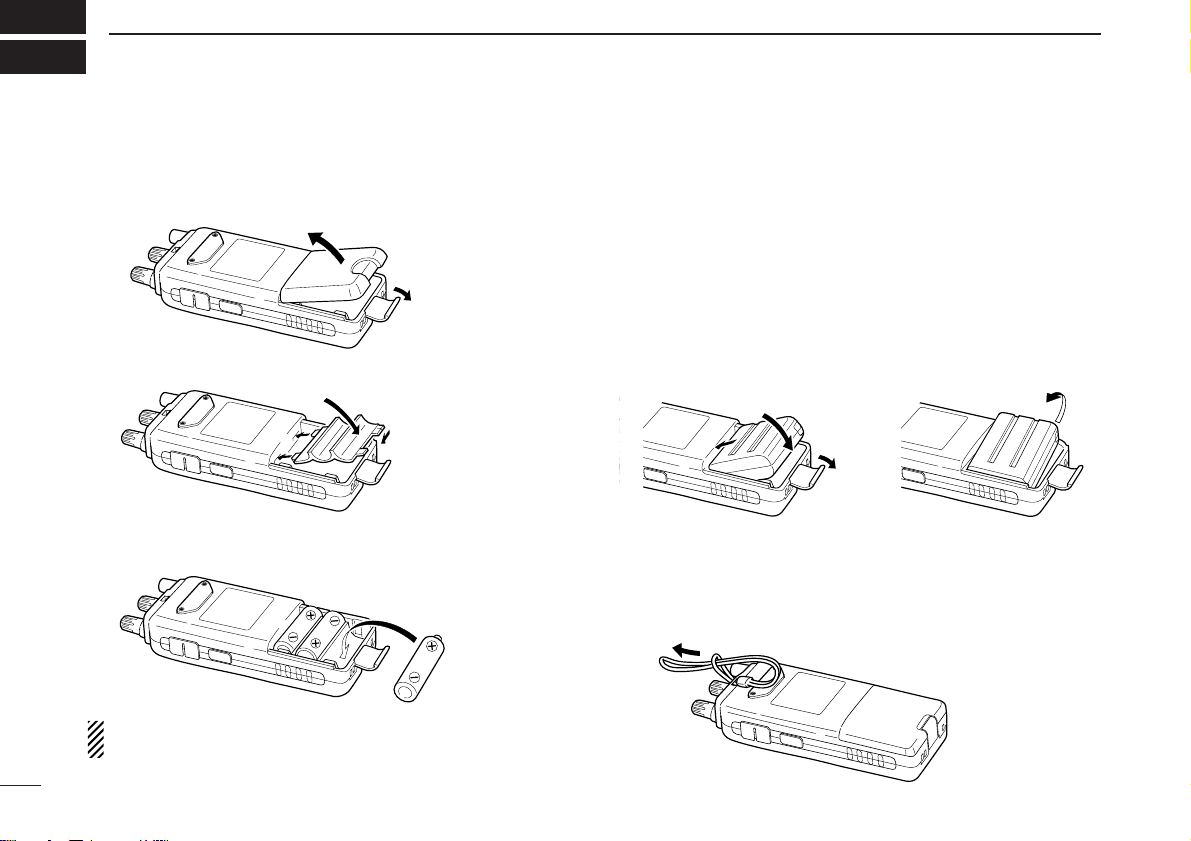
I
QUICK REFERENCE GUIDE
■ Preparations
D Batteries installation
qRemove the battery cover from the receiver.
wFor alkaline battery use, attach the supplied battery spacer.
eInstall 3 R6 (AA) size alkaline batteries.
• Be sure to observe the correct polarity.
Keep the battery contacts clean to avoid rust or poor contact.
It’s a good idea to clean the battery terminals once a week.
DD
Battery pack installation
q Remove the battery cover from the receiver.
w Remove the supplied battery spacer for R6 (AA) size bat-
tery use.
e Install the Li-Ion battery pack (BP-206).
• Be sure to observe the correct direction.
• Charge Li-Ion battery pack (BP-206) before use. (Refer to p. IV
for charging instructions.)
D Handstrap
Slide the handstrap through the loop on the top of the rear
panel as illustrated at below. Facilitates carrying.
w
q
e
•Battery pack installation
•Battery pack removal
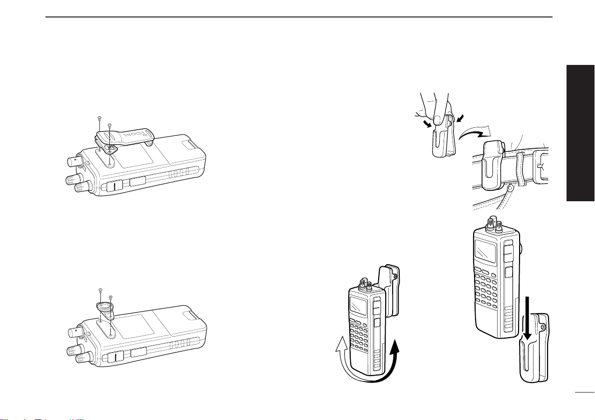
II
QUICK REFERENCE GUIDE
D Belt clip
Conveniently attaches to your belt.
Attach the belt clip with the supplied screws using a phillips
screwdriver.
D Swivel belt clip (Option)
The optional swivel belt clip (MB-86) is useful for easy
attaching/detaching the receiver to/from the belt.
q Attach the stopper with the supplied screws using a phillips
screwdriver.
w Clip the belt clip to your belt.
e Insert the receiver into the end of
the clip as shown at right.
• Once the receiver is locked in
place, it will swivel 360 degrees.
Quick reference guide
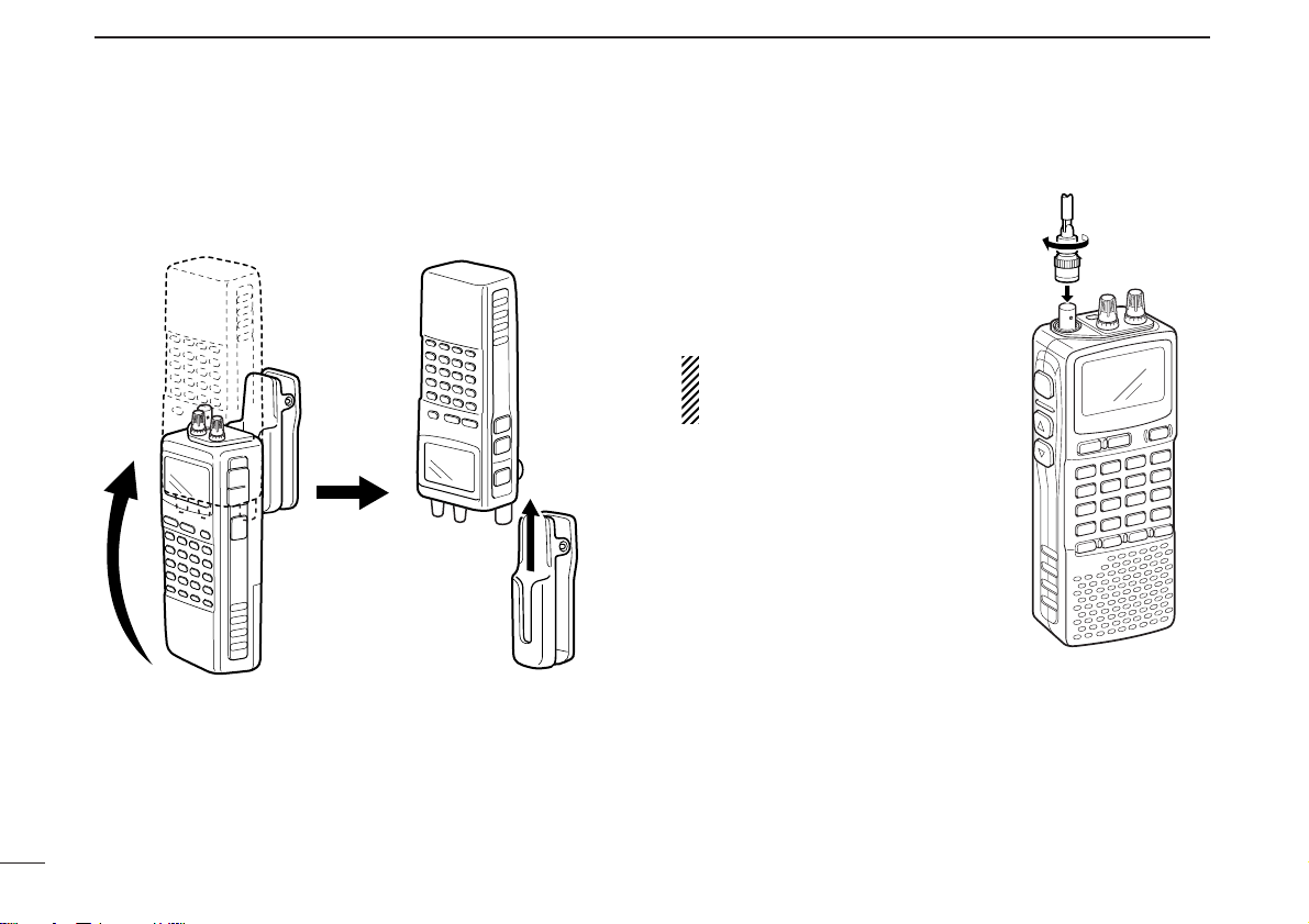
III
QUICK REFERENCE GUIDE
To remove:
r Turn the receiver upside down, and then lift to release the
receiver from the belt clip as shown at upper right.
DD
Antenna
Insert the supplied antenna into
the antenna connector and
screw down the antenna as
shown at right.
NEVER hold the antenna when
carrying the receiver.
✔
For your information
Third-party antennas may increase receiver performance.
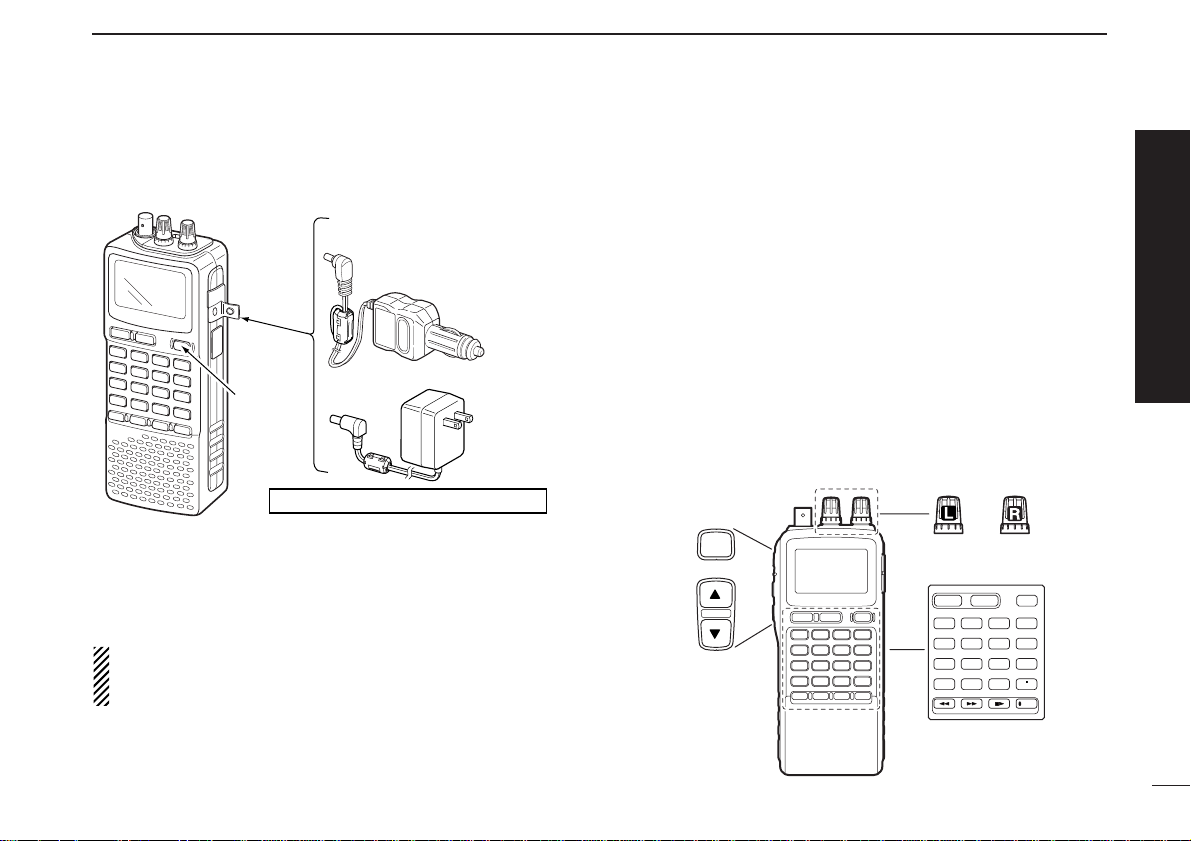
IV
QUICK REFERENCE GUIDE
D Charging the battery
qInstall the battery pack (BP-206).
wPlug the AC adaptor into an AC outlet.
eTurn OFF the receiver, then insert the adaptor plug into the
[DC] jack of the receiver.
RR
WARNING!:
NEVER attempt to charge any other batteries. Because
the IC-R20 can charge the BP-206 only.
Keep the jack cover attached when jack is not in use to protect the connectors from dust and moisture.
■ Your first scanning
experience
Now that you have your IC-R20 ready, you are probably excited to start listening. We would like to take you through a
few basic operation steps to make your first “Scanning Experience” enjoyable.
D About default setting
The frequency control ([R-DIAL]) function can be traded with
volume control ([L-DIAL] and [YY]/[ZZ] keys) function by pushing for 1 sec. [1 DIAL.SEL]. However, in this QUICK REFERENCE GUIDE, the factory default setting ([R-DIAL] sets
operating frequency) is used for simple instruction.
123
4560
789
BAND
DUALWATCH
MAIN/SUB
POWER
VFO
MHz
MODE
SCANMRS.MW
SCOPE
LOCK
REC
AFC
SQL
Top
Left
Front
IC-R20
to [DC]
jack
Turn power
OFF.
Charging periods: 8 hours (w/BP-206)
Optional CP-18A/E
Cigarette lighter cable
with DC-DC converter
AC adaptor
BC-149A/D
to cigarette
lighter socket
to AC outlet
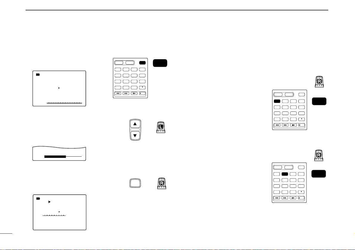
V
QUICK REFERENCE GUIDE
D Basic operation
1. Turning ON the receiver
➥ Push [POWER] for 1 sec. to
turn the power ON.
2. Adjusting audio level
➥ Rotate [L-DIAL] (or push [YY]/
[ZZ]) to set the desired audio
level.
3. Adjusting squelch level
➥ While pushing [SQL], rotate [R-
DIAL] to set the squelch level.
4. Tune the desired frequency
The tuning dial will allow you to dial in the frequency you want
to operate. Pages 9 and 15 will instruct you on how to set the
tuning speed.
[Using the tuning dial]
qPush [BAND] several times
to select the desired frequency band.
• While pushing [BAND], rotate
[R-DIAL] also select frequency
band.
wRotate [R-DIAL] to set the
desired receive frequency.
• Push [VFO MHz] for 1 sec. then
rotate [R-DIAL] to change the
frequency in 1 MHz steps, or
push for 1 sec. again then rotate
[R-DIAL] to change the frequency in 10 MHz steps. (Each
push for 1 sec. toggles 1 MHz or
10 MHz tuning steps.)
MODE
FM
146 010
√
√
VOL
MODE
FM
146 010
√
SQUELCH:LEVEL9
PSKIP
PSKIP
DUALWATCH
MAIN/SUB
VFO
MODE
BAND
MHz
SCANMRS.MW
123
4560
789
SQL
Left
POWER
POWER
SCOPE
AFC
LOCK
REC
Front
TopLeft
Top
Top
DUALWATCH
MAIN/SUB
BAND
123
4560
789
DUALWATCH
BAND
123
4560
789
POWER
VFO
MODE
MHz
SCANMRS.MW
BAND
SCOPE
AFC
LOCK
REC
Front
Top
MAIN/SUB
POWER
VFO
MODE
MHz
SCANMRS.MW
VFO
MHz
SCOPE
AFC
LOCK
REC
Front
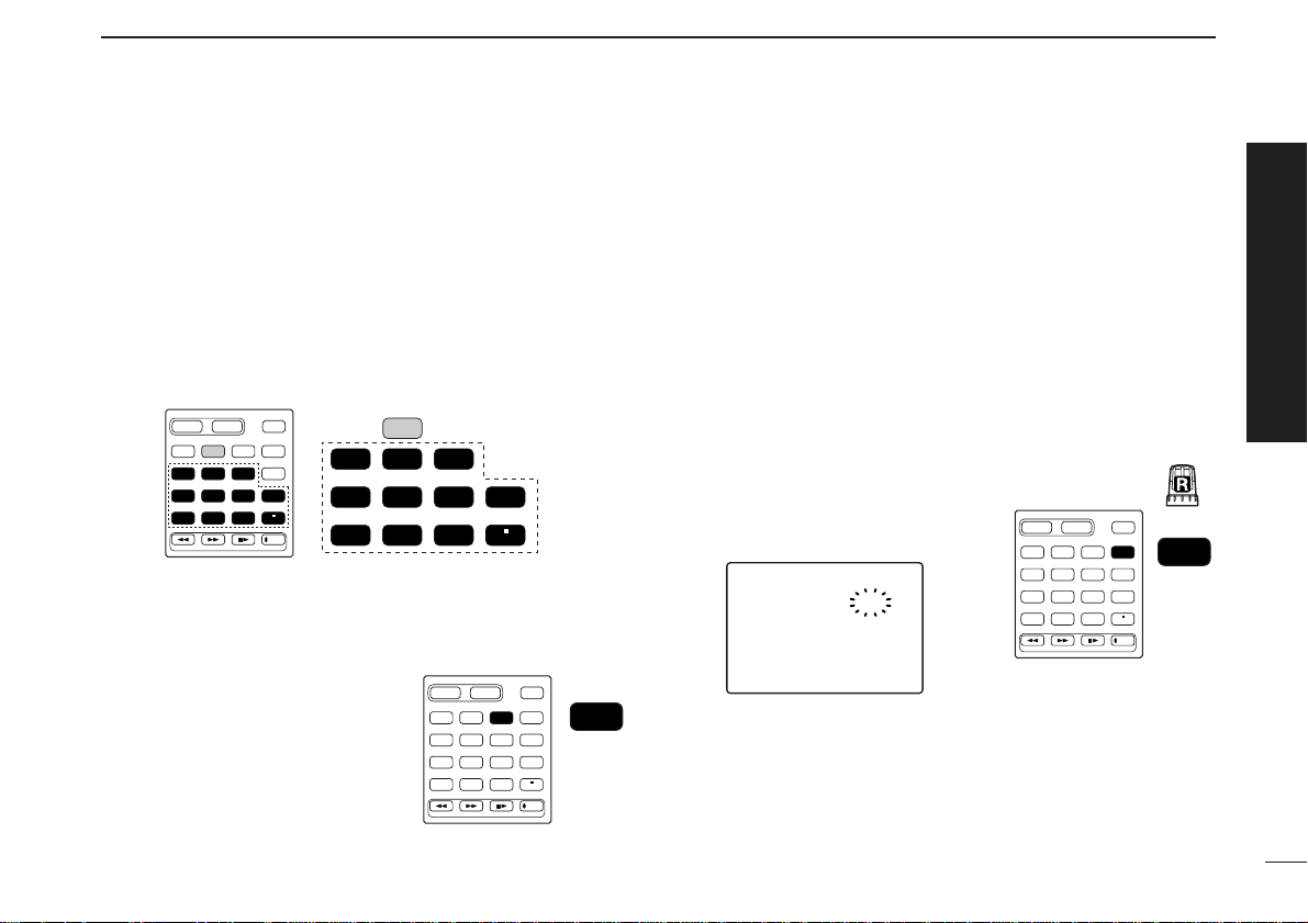
VI
QUICK REFERENCE GUIDE
[Using the keypad]
➥ E
nter the desired frequency
via the keypad.
• Direct input can be set until 1 kHz digit, rotate [R-DIAL] to set
below 1 kHz frequency after set tuning steps, if necessary. (See
p. 14 for setting the tuning step.)
• Pushing [VFO MHz] omits the entry of 100 kHz and below, when
you want to edit to these digits “0.”
• Push [DUALWATCH] to cancel the entry.
5. Receive mode selection
➥ Push [MODE SCAN] several
times to select the desired receive mode.
• FM, WFM, AM, LSB, USB and
CW are available.
■ Memory programming
The IC-R20 has a total of 1250 memory channels (including
200 auto write channels and 50 scan edges) for storing often
used receive frequency, mode, etc.
1. Setting frequency
In VFO mode, set the desired receive frequency mode.
• When “
µµ
” indicator is displayed, push [VFO MHz] to select the
VFO mode.
2. Selecting a memory
channel
Push [MR S.MW] for 1 sec.,
then
rotate [R-DIAL] to select the desired memory channel.
•“µµ” indicator blinks.
3. Writing a memory channel
Push [MR S.MW] for 1 sec. until 3 beeps sound.
• Memory channel number automatically increases when continuing
to push [MR S.MW] after programming.
FM
>CLEARCLEAR
—SKIPSKIP—:OFF:OFF
—MNAME:MNAME:
-BNAME:-BNAME:
—BANKBANK—:—-:—-
999999
µ
.
146.010
123
4560
789
BAND
DUALWATCH
MAIN/SUB
POWER
VFO
MHz
MODE
SCANMRS.MW
SCOPE
LOCK
REC
AFC
MR
S.MW
Front
Top
123
4560
789
BAND
DUALWATCH
MAIN/SUB
POWER
VFO
MHz
MODE
SCANMRS.MW
SCOPE
LOCK
REC
AFC
MODE
SCAN
Front
DUALWATCH
MAIN/SUB
VFO
MODE
BAND
MHz
SCANMRS.MW
123
4560
789
POWER
SCOPE
AFC
LOCK
REC
VFO
MHz
123
4560
789
AFC
LOCK
Front
VII
QUICK REFERENCE GUIDE
■ Programmed scan operation
25 pairs, 50 channels of memories are used for programmed
scan operation, that specify a scanning range. The programmed scan scans between “xxA” and “xxB” (xx=00 to 24)
frequencies. Therefore, before operating the programmed
scan, different frequencies must be programmed into “A” and
“B” channels.
DD
Programming scan edges
Astart frequency must be programmed into a “xxA,” and end
frequency must be programmed into a “xxB” memory channel.
1. Setting frequency
In VFO mode, set the desired receive frequency mode.
• When “
µµ
” indicator is displayed, push [VFO MHz] to select the
VFO mode.
2. Selecting a scan edge
channel “A”
Push [MR S.MW] for 1 sec.,
then
rotate [R-DIAL] to select one of
the desired scan edge channel
“A.”
•“µµ” indicator blinks.
3. Writing a memory channel
Push [MR S.MW] for 1 sec. until
3 beeps sound.
• Scan edge channel “B” is automatically selected when continuing to
push [MR S.MW] after program-
ming.
• After programming is completed,
return to VFO indication.
4. Selecting a scan edge
channel “B”
Push [MR S.MW] for 1 sec.,
then ro-
tate [R-DIAL] to select one of the
desired scan edge channel “B.”
•“µµ” indicator blinks.
• When the scan edge channel “B” is already selected at step 3. (continuing to
push [MR S.MW] after programming),
skip this step.
5. Writing a memory channel
Push [MR S.MW] for 1 sec. until 3 beeps sound.
• The next scan edge channel “A” is automatically selected when continuing to push [MR S.MW] after programming.
• After programming is completed, return to VFO indication.
FM
-BNAME:-BNAME:
—BANKBANK—:—-:—-
03B03B
µ
.
146.010
123
4560
789
BAND
DUALWATCH
MAIN/SUB
POWER
VFO
MHz
MODE
SCANMRS.MW
SCOPE
LOCK
REC
AFC
MR
S.MW
Front
Top
123
4560
789
BAND
DUALWATCH
MAIN/SUB
POWER
VFO
MHz
MODE
SCANMRS.MW
SCOPE
LOCK
REC
AFC
MR
S.MW
Front
FM
-BNAME:-BNAME:
—BANKBANK—:—-:—-
03A03A
µ
.
146.010
123
4560
789
BAND
DUALWATCH
MAIN/SUB
POWER
VFO
MHz
MODE
SCANMRS.MW
SCOPE
LOCK
REC
AFC
MR
S.MW
Front
Top
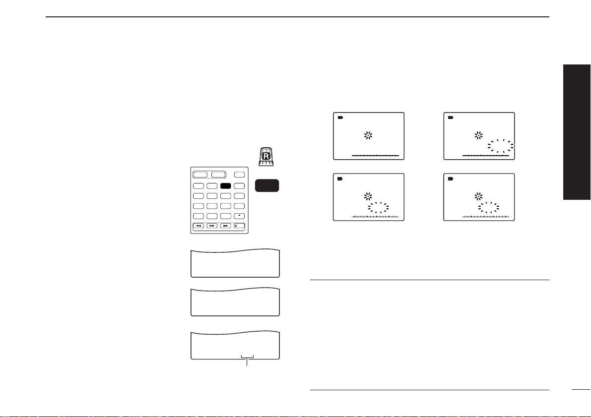
VIII
QUICK REFERENCE GUIDE
DD
Starting scan
1. Select VFO mode.
Push [VFO MHz] to select the VFO mode for full, band and
programmed scan operation.
• Select memory mode by pushing [MR S.MW] for memory or bank
scan.
2. Selecting a scanning type
While pushing and holding
[MODE SCAN],
rotate [R-DIAL]
to select one of the desired
scanning type.
•Available scan types when VFO
mode is selected; “ALL” for full
scan; “BAND” for the selected
band; one of “PROGxx” (xx=0 to
24) for programmed scan.
•Available scan types when memory
bank is selected; “ALL” for all memory scan, “BANK-LINK” for banklink scan; “BANK” for the selected
bank scan.
3. Starting scan
Release [MODE SCAN] to start the scan.
• Rotate [R-DIAL] to change the scanning direction.
4. Cancelling scan
Push [DUALWATCH] to stop the scan.
✔
For your information
The memory channel number you program the scan edges
into correlate “PROGxx” as follows:
00A/00B: Scans between frequencies programmed in 00A
and 00B channels, and select “PROG-00”
01A/01B: Scans between frequencies programmed in 01A
and 01B channels, and select “PROG-01”
•
•
•
24A/24B: Scans between frequencies programmed in 24A
and 24B channels, and select “PROG-24”
√
MODEMODE
ANL
AFCTSQL
FMFM
148 888 148 8880 000 0 000
PSPSKIKIP
-DUP
√
MODEMODE
ANL
AFCTSQL
FMFM
PSPSKIKIP
-DUP
P01
• During full/band scan • During programmed scan
√
µ
MODEMODE
ANL
AFCTSQL
FMFM
888 888 888 888000 000
PSKIP
-DUP
012
√
µ
MODEMODE
ANL
AFCTSQL
FMFM
000 000
PSKIP
-DUP
P01
• During memory/all/bank scan • During bank scan
123
4560
789
BAND
DUALWATCH
MAIN/SUB
POWER
VFO
MHz
MODE
SCANMRS.MW
SCOPE
LOCK
REC
AFC
MODE
SCAN
SCAN:ALL
√
PSKIP
SCAN:BAND
√
PSKIP
SCAN:PROG-01
√
PSKIP
• Full scan
• Band scan
• Programmed scan
Selectable between “00” to
“24” if programmed
Front
Top
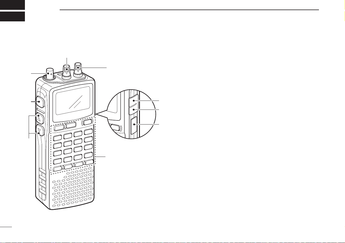
■ Front, top and side panels
qANTENNA CONNECTOR (p. II)
BNC connector: Connects the supplied antenna.
wSQUELCH KEY [SQL] (p. 18)
➥ Push and hold to temporarily open the squelch and
monitor the operating frequency.
➥ While pushing this key, rotate the tuning dial* to adjust
the squelch level.
eUP/DOWN KEYS [YY]/[ZZ]
Adjust audio volume level.* (p. 17)
rUSB JACK [USB]
Connects to a PC using an optional OPC-1382
CLONING
CABLE
for cloning. Cloning allows you to quickly and easily
transfer the programmed contents between the IC-R20
and the connected PC.
tEXTERNAL DC-IN CONNECTOR [DC] (p. 9)
Connects an AC adaptor or an optional cigarette lighter
cable for both charging the installed re-chargeable battery
pack and operating.
yEXTERNAL SPEAKER CONNECTOR [SP/CI-V]
➥ Connect an optional earphone or headphone.
The internal speaker will not function when any external equipment is connected. (See p. 80 for a list of
available options.)
➥ Connect an optional CT-17 for remote control operation.
(p. 68)
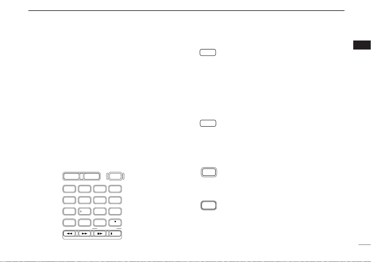
2
1
PANEL DESCRIPTION
1
uLEFT DIAL [L-DIAL]
➥ During single band operation, rotate to adjust audio vol-
ume level.* (p. 17)
➥ During dualwatch operation, activates as the tuning dial
for upper side on the display.*
iRIGHT DIAL [R-DIAL]
➥ Rotate to select the operating frequency.* (p. 12)
➥ While scanning, changes the scanning direction.*
(p. 26)
➥ While pushing [SQL], sets the squelch level.* (p. 18)
➥ While pushing [VFO MHz], sets the operating frequency
in 1 MHz or 10 MHz in VFO mode.* (p. 14)
➥ While pushing [BAND], selects the operating band in
VFO mode.* (p. 14)
➥ While dualwatch operation, activates as the tuning dial
for lower side on the display.* (p. 14)
KEYPAD
qDUALWATCH/CLEAR KEY [DUALWATCH]
➥ Push for 1 sec. to toggle between single band
and dualwatch operation. (p. 24)
➥ Clears numeric key input. (p. 15)
➥ Returns to previous operating condition while
setting frequency or memory channel, or while
in set mode.
➥ Cancels the band scope or scan function, etc.
(pgs. 22, 35)
wMAIN/SUB KEY [MAIN/SUB] (p. 24)
➥ During dualwatch operation, push to select the
MAIN band or SUB band.
➥ During dualwatch operation, push for 1 sec. to
exchange the upper frequency and lower frequency.
ePOWER KEY [POWER]
Push for 1 sec. to turn the receiver power ON
and OFF.
rBAND KEY [BAND]
Push to select the operating frequency band.
(p. 12)
DIAL.SEL SWEEP CENTER
T-SCAN SKIP M.N
TONE SET TS
ATT RF GAIN
IC Recorder
123
4560
789
BAND
DUALWATCH
MAIN/SUB
POWER
VFO
MHz
MODE
SCANMRS.MW
SCOPE
LOCK
REC
AFC
*The function of tuning control and volume control can be traded. See
page 23 for details.

3
1
PANEL DESCRIPTION
t VFO/MHz KEY [VFO MHz]
➥ Push to select VFO mode. (p. 11)
➥ Push for 1 sec. to toggle between the 1 MHz
or 10 MHz tuning steps (p. 14)
y MODE/SCAN KEY [MODE SCAN]
➥ Push to select the operating mode (FM, WFM,
AM, USB, LSB, CW). (p. 16)
➥ Push for 1 sec. to start a scan. (p. 35)
u MEMORY KEY [MR S.MW]
➥ Push to select between memory mode, TV
channel and PreSet channel. (p. 11)
➥ Push for 1 sec. to enter memory write condi-
tion. (p. 26)
➥ Push for 2 sec. to write the operating fre-
quency into the selected memory channel in
VFO mode.
Push [MR S.MW] for 2 sec. to transfer the dis-
played frequency into the VFO in memory
mode. (p. 31)
i VOLUME/DIAL KEY [1 DIAL.SEL]
➥ Inputs digit ‘1’ for frequency input, memory
channel selection, etc.
➥ Push for 1 sec. to trade the volume control
([L-DIAL], [YY]/[ZZ]) and tuning control ([RDIAL]) functions. (p. 23)
•“
√√
” appears when the normal operation.
•“
∂∂
” appears when the functions of the tuning
control and volume control are traded.
o SWEEP KEY [2 SWEEP] (p. 22)
➥ Inputs digit ‘2’ for frequency input, memory
channel selection, etc.
➥ Push for 1 sec. to select the tuning step for
band scope function. Once this key is pushed,
the band scope function sweeps once via the
new tuning step.
!0 CENTER KEY [3 CENTER] (p. 22)
➥ Inputs digit ‘3’ for frequency input, memory
channel selection, etc.
➥ Push for 1 sec. to return the display frequency
of the band frequency.
!1 SCOPE KEY [SCOPE] (p. 22)
➥ Push to activate the band scope function dur-
ing normal operating condition. Or push to
stop continuous sweeping.
➥ Push for 1 sec. to start continuous sweeping.

4
1
PANEL DESCRIPTION
1
!2 TONE SCAN KEY [4 T-SCAN]
➥ Inputs digit ‘4’ for frequency input, memory
channel selection, etc.
➥ Push for 1 sec. to start a tone scan. (p. 48)
!3 FREQUENCY SKIP KEY [5 SKIP]
➥ Inputs digit ‘5’ for frequency input, memory
channel selection, etc.
➥ Push for 1 sec. to turn the frequency skip
function ON and OFF in VFO mode. (p. 39)
• “PSKIP” appears when the frequency skip function
is in use.
➥ Push for 1 sec. to set the memory channel as
the following skip channel in memory mode in
order. (p. 39)
• Skip channel — “SKIP” appears.
• Frequency skip channel — “PSKIP” appears.
• Non-skip channel — no skip indicator appears.
➥ Push for 1 sec. to program a paused fre-
quency as a skip frequency while scanning.
(p. 39)
!4 MEMORY NAME KEY [6 M.N]
➥ Inputs digit ‘6’ for frequency input, memory
channel selection, etc.
➥ Push for 1 sec. to turn the memory name indi-
cation ON and OFF. (p. 30)
!5 AFC KEY [0 AFC]
➥ Inputs digit ‘0’ for frequency input, memory
channel selection, etc.
➥ Push for 1 sec. to turn the AFC (Automatic
Frequency Control) function ON and OFF.
(p. 21)
!6 TONE SQUELCH KEY [7 TONE]
➥ Inputs digit ‘7’ for frequency input, memory
channel selection, etc.
➥ Push for 1 sec. to activate the following tone
squelch functions in order.
•Tone squelch — “TSQL” appears. (p. 45)
• Pocket beep — “TSQLS” appears. (p. 45)
• DTCS squelch — “DTCS” appears. (p. 45)
• DTCS beep — “DTCSS” appears. (p. 45)
• VSC function — “VSC” appears. (p. 45)
• No tone operation — no tone indicator appears.
!7 SET MODE KEY [8 SET]
➥ Inputs digit ‘8’ for frequency input, memory
channel selection, etc.
➥ Push for 1 sec. to enter the set mode.
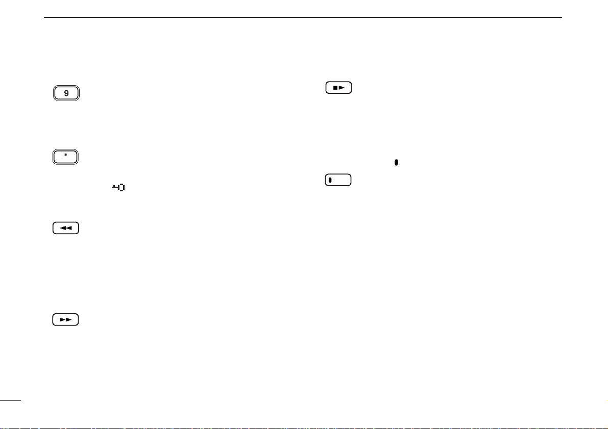
5
1
PANEL DESCRIPTION
!8 TUNING STEP KEY [9 TS]
➥ Inputs digit ‘9’ for frequency input, memory
channel selection, etc.
➥ Push for 1 sec. to select the tuning step.
(p. 14)
!9 LOCK KEY [• LOCK]
➥ Inputs MHz digit for frequency input. (p. 15)
➥ Push for 1 sec. to toggle the lock function ON
and OFF. (p. 16)
•“ ” appears while the key lock function is in use.
@0 REWIND/ATTENUATOR KEY [
ΩΩΩΩ
ATT]
➥ Push to select the track for recorded audio.
(p. 64)
➥ Push and hold to rewind during playing the
recorded audio. (p. 64)
➥ Push for 1 sec. to turn the attenuator function
ON and OFF during normal operation. (p. 19)
@1 FAST FORWARD/RF GAIN KEY [
≈≈≈≈
RF GAIN]
➥ Push to select the track for recorded audio.
(p. 64)
➥ Push and hold to fast forward through the
recorded contents. (p. 64)
➥ Push for 1 sec. to enter the RF GAIN set
mode. Push to select the level after selecting
with [R-DIAL]. (p. 19)
@2 STOP/PLAY [■
≈≈
]
➥ Push to start the recorded audio. (p. 64)
➥ Push to stop the recording or playing audio.
(p. 64)
➥ Push for 1 sec. to enter the play speed set
mode. Push to select the item after selecting
with [R-DIAL]. (p. 65)
@3 RECORD KEY [ REC]
➥ Push to start recording audio. (p. 64)
➥ Push to pause recording audio. (p. 64)
➥ Push for 1 sec. to enter the record set mode.
Push to select the item after selecting with [RDIAL]. (p. 65)
LOCK
ATT
RF GAIN
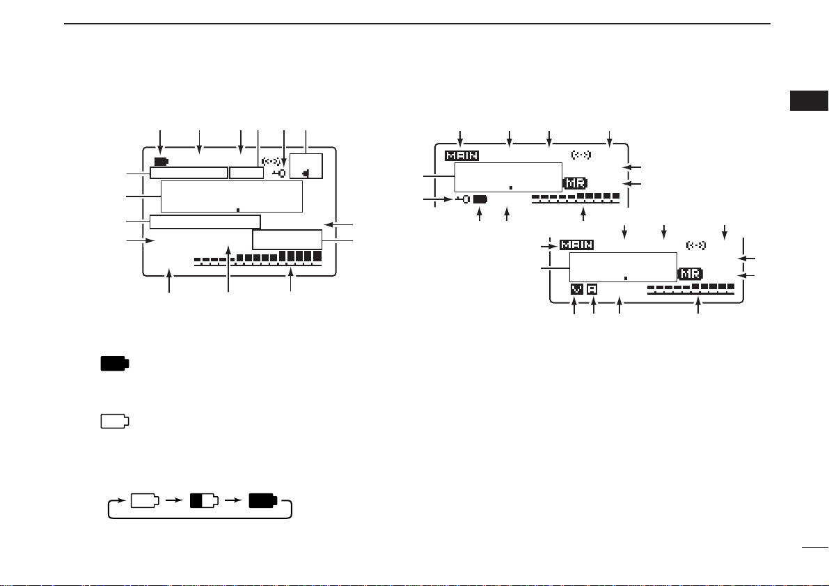
6
1
PANEL DESCRIPTION
1
■ Function display
qBATTERY INDICATOR
➥ “” appears when the installed batteries have
ample capacity.
• They do not appear when operating with an external power
source.
➥ “” appears when the batteries are nearing ex-
haustion.
• IC-R20 installed the BP-206 must be charged presently, but
when it installed alkaline batteries can be operate for a while.
➥ Scrolls while charging the installed BP-206. (p. 
➥ Battery indicator blinks when completely charged.
wDUPLEX INDICATORS (p. 20)
“+DUP” appears when plus semi-duplex, “–DUP” appears
when minus semi-duplex (repeater) operation is selected.
eSIGNAL SQUELCH INDICATORS
➥ “TSQL” appears while the tone squelch function is in
use. (p. 45)
➥ “DTCS” appears while the DTCS squelch function is in
use. (p. 45)
➥ “S” appears with the “TSQL” or “DTCS” indicator
while the pocket beep function
(with CTCSS or DTCS) is
in use. (p. 45)
➥ “VSC” appears while the VSC (Voice Squelch Control)
function is in use. (p. 45)
MODE
!5
!4
!3
M:Amateur2
!2
√
-DUP
145 000
TSQL
FM
PRIRIO
ANL
ATT
!1
!0
µ
AFC
PSKIP
000
o
u
i
!6
!4
t
145 000
w
-DUP
e
TSQL
u
PS
PRIO
000
FM
!1
w
-DUP
FM
!5
!5
!6
!4
o
433 000
!2
!0
i
e
TSQL
PRIO
000
o
u
PS
!0
i

7
1
PANEL DESCRIPTION
rANL/NB INDICATOR (pgs. 21, 52)
➥ “ANL” appears when the ANL (Automatic Noise Limitter)
function is in use. The ANL function is available only for
AM mode.
➥ “NB” appears when the noise blanker function is in use.
The noise blanker function is available while in
LSB/USB/CW modes.
tLOCK INDICATOR (p. 16)
Appears when the lock function is activated.
yAFC INDICATOR (p. 21)
Appears when the AFC function is activated.
• The AFC function is available for single band operation only.
uSKIP INDICATORS (p. 39)
➥ “SKIP” appears when the selected memory channel is
specified as a skip channel.
➥ “PSKIP” appears when the displayed frequency is spec-
ified as a skip frequency.
iCHANNEL SELECTION INDICATOR (p. 11)
➥ “µµ” and three digits channel number appear when
memory channel is selected.
➥ “åå” and three digits channel number appear when
auto-memory write channel is selected.
➥ “
TV” appears when TV channel is selected.
➥ (
0–9) channel number appears when PreSet channel
is selected.
➥ “
WX”* appears when weather channel is selected.
*Available for the USA version only. “åå,” “
0–9” and “TV”
indications appear for single band operation only.
oSIGNAL STRENGTH INDICATOR
Shows the receiving signals relative to signal strength.
!0PRIORITY WATCH INDICATOR (p. 42)
Appears when priority watch is in use.
!1ATTENUATOR INDICATOR (p. 19)
Appears when the RF attenuator is in use.
!2VOLUME/DIAL EXCHANGE INDICATOR (p. 23)
➥ “
√√
” appears when the normal operation.
➥ “
∂∂
” appears when the functions of the tuning con-
trol and volume control are traded.
!3MEMORY/BANK NAME INDICATOR
Shows the memory name or bank name.
• This indication is available when memory name or bank name is
programmed.
!4FREQUENCY READOUT
Shows an operating frequency.
• The smaller readout appears at right when tuning step is selected 0.1 kHz or 0.01 kHz steps.
• The decimal point blinks during scan.
!5RECEIVE MODE INDICATOR (p. 16)
Shows the selected receive mode.
• FM, WFM AM, LSB, USB and CW are available.
!6MAIN BAND INDICATOR (p. 24)
Shows the main band on upper display or lower display.
• This indication appears only when dualwatch operation.
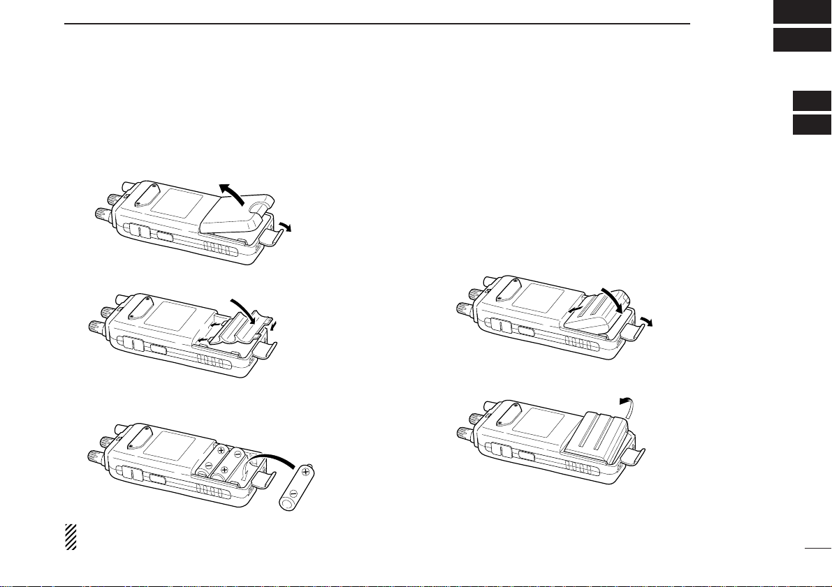
8
2
BATTERY INSTALLATION/CHARGING
1
2
■ Battery installation
Make sure receiver power is turned OFF before installing or
replacing the batteries.
qRemove the battery cover from the receiver.
wFor alkaline battery use, attach the supplied battery spacer.
eInstall 3 R6 (AA) size alkaline batteries.
• Be sure to observe the correct polarity.
Keep the battery contacts clean to avoid rust or poor contact.
It’s a good idea to clean the battery terminals once a week.
DD
Battery pack installation
q Remove the battery cover from the receiver.
w Remove the supplied battery spacer for R6 (AA) size bat-
tery use.
e Install the Li-Ion battery pack (BP-206).
• Be sure to observe the correct direction.
• Charge the Li-Ion battery pack before use.
w
q
e
•Battery pack installation
•Battery pack removal
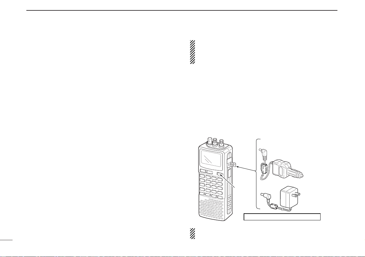
■ Caution
DD
Battery caution
CAUTION! NEVER short the battery terminals. Current will
flow into metal objects, so be careful when placing battery
pack in handbags, etc.
NEVER incinerate used battery packs or battery cells. Internal
battery gas may cause explosion.
NEVER mix old and new batteries. Make sure all battery cells
are the same brand, type and capacity.
Either of the above may cause a fire hazard or damage the
receiver if ignored.
DD
Charging caution
Recommended temperature for charging:
±0˚C to +35˚C (; +32˚F to +95˚F)
Connect the supplied (or optional for some versions) AC
adaptor or optional cigarette lighter cable only when charging
the battery pack (BP-206). NEVER use other manufacture’s
chargers.
AVOID leaving the battery pack in a fully charged, or completely discharged condition for long time. It causes shorter
battery life. In case of leaving the battery pack unused for a
long time, it must be kept safely after discharge, or use the
battery for 2 or 3 hours, then remove it from the receiver.
If your battery pack seems to have no capacity even after
being charged, fully charge the battery pack again. If the battery pack still does not retain a charge (or very little), a new
battery pack must be purchased.
CAUTION: BE SURE to disconnect the CP-18A/E from
the cigarette lighter socket when charging is finished, because, a slight current still follows in the CP-18A/E and the
vehicle’s battery will become exhausted.
■ Battery charging
DD
Regular charging
q Insert the battery pack (BP-206) into the receiver. (p.
wPlug the AC adaptor (BC-149A/D*) into an AC outlet; or the
optional CP-18A/E into a cigarette lighter socket.
* Not supplied with some versions.
eTurn OFF the receiver, then insert the adaptor plug into
[DC] of the receiver.
RR
WARNING!: NEVER attempt to charge any other bat-
teries. Because the IC-R20 can charge the BP-206 only.
9
2
BATTERY INSTALLATION/CHARGING
IC-R20
to [DC]
jack
Turn power
OFF.
Charging periods: 8 hours (w/BP-206)
Optional CP-18A/E
Cigarette lighter cable
with DC-DC converter
to cigarette
lighter socket
AC adaptor
BC-149A/D
to AC outlet
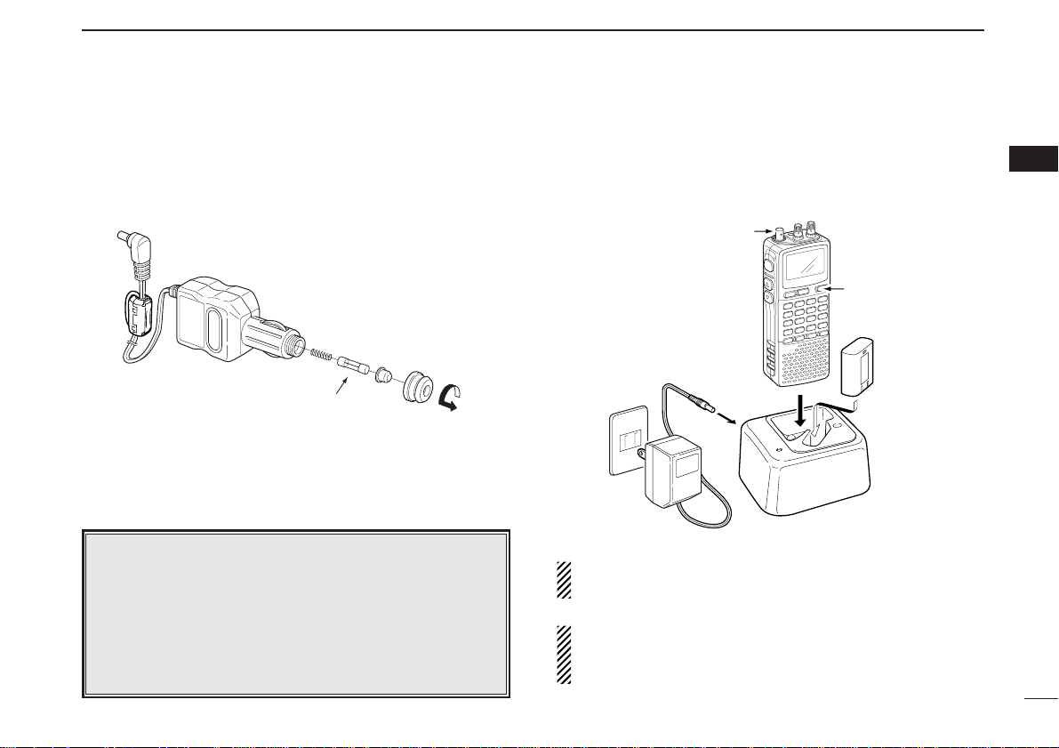
10
2
BATTERY INSTALLATION/CHARGING
2
DD
CP-18A/E fuse replacement
If the fuse blows or the receiver stops functioning while operating with the optional CP-18A/E, find the source of the problem if possible, and replace the damaged fuse with a new
rated one (FGB 5 A) as shown below.
DD
Rapid charging with the BC-156
The optional BC-156 provides rapid charging of battery pack
(BP-206).
• Charging periods: 2.5 hours (w/BP-206)
CAUTION: Shorten or remove the telescoping antenna be-
fore charging to prevent the receiver from overturning.
If the charge indicator flashes orange, there may be a
problem with the battery pack (or charger). Reinsert the
battery pack or contact your dealer.
Recommendation:
Charge the supplied battery pack for a maximum of
8 hours. Li-Ion batteries are different from Ni-Cd batteries in that it is not necessary to completely charge
and discharge them to prolong the battery life. Therefore, charging the battery in intervals, and not for extended periods is recommended.
Fuse 5 A
Shorten or remove
the antenna.
Turn power OFF.
AC adaptor
(supplied with BC-156)
BC-156
Check the
orientation.
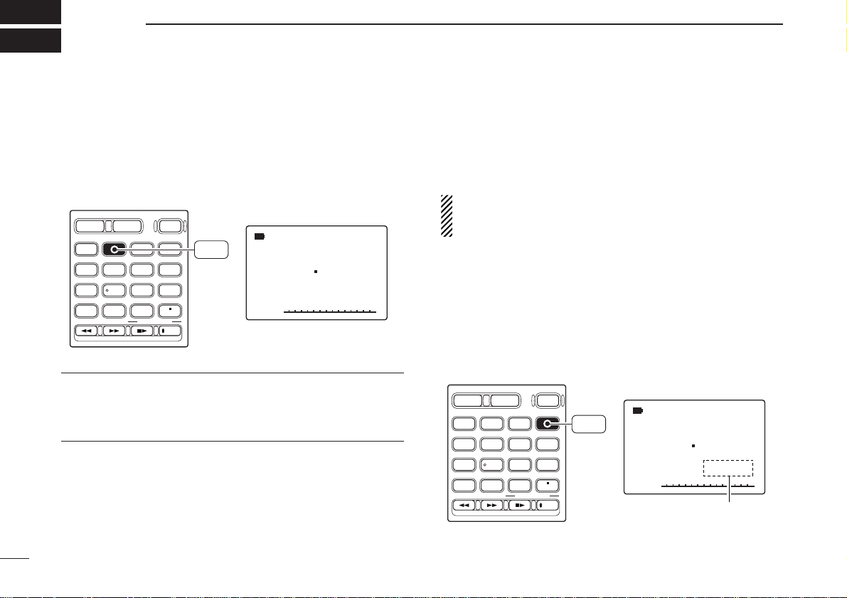
11
FREQUENCY AND CHANNEL SETTING
3
■ Mode selection
DD
VFO mode
VFO mode is used for the desired frequency setting within the
frequency coverage.
➥ Push [VFO MHz] to select VFO mode.
What is VFO?
VFO is an abbreviation of Variable Frequency Oscillator. Frequencies for receiving are generated and controlled by the
VFO.
DD
Memory mode/PreSet*/TV*/Weather†channels
Memory mode is used for operation of memory channels
which have programmed frequencies. PreSet channels are
used for most-often used frequencies for quick recall.
*Appears only when PreSet channels/TV channels are
programmed via the optional CS-R20.
†
Available for the USA version only.
qPush [MR S.MW] several times to select the channel type.
• Memory/PreSet/TV /Weather channels can be selected in sequence
wRotate [R-DIAL] to select the desired channel.
• Only programmed memory channels can be selected.
• Entering keypad directly can be selected the desired memory
channel.
• See p. 26 for memory programming details.
√
µ
MODE
ANL
AFCTSQL
FM
146 100
PSKIP
-DUP
001
DIAL.SEL SWEEP CENTER
T-SCAN SKIP M.N
TONE SET TS
ATT RF GAIN
IC Recorder
123
4560
789
BAND
DUALWATCH
MAIN/SUB
POWER
VFO
MHz
MODE
SCANMRS.MW
SCOPE
LOCK
REC
AFC
“µ ” and memory channel
number appear.
• Memory mode indication
MR
S.MW
DIAL.SEL SWEEP CENTER
T-SCAN SKIP M.N
TONE SET TS
ATT RF GAIN
IC Recorder
123
4560
789
BAND
DUALWATCH
MAIN/SUB
POWER
VFO
MHz
VFO
MHz
MODE
SCANMRS.MW
SCOPE
LOCK
REC
AFC
√
MODE
ANL
AFCTSQL
FM
146 560
PSKIP
-DUP
• VFO mode indication
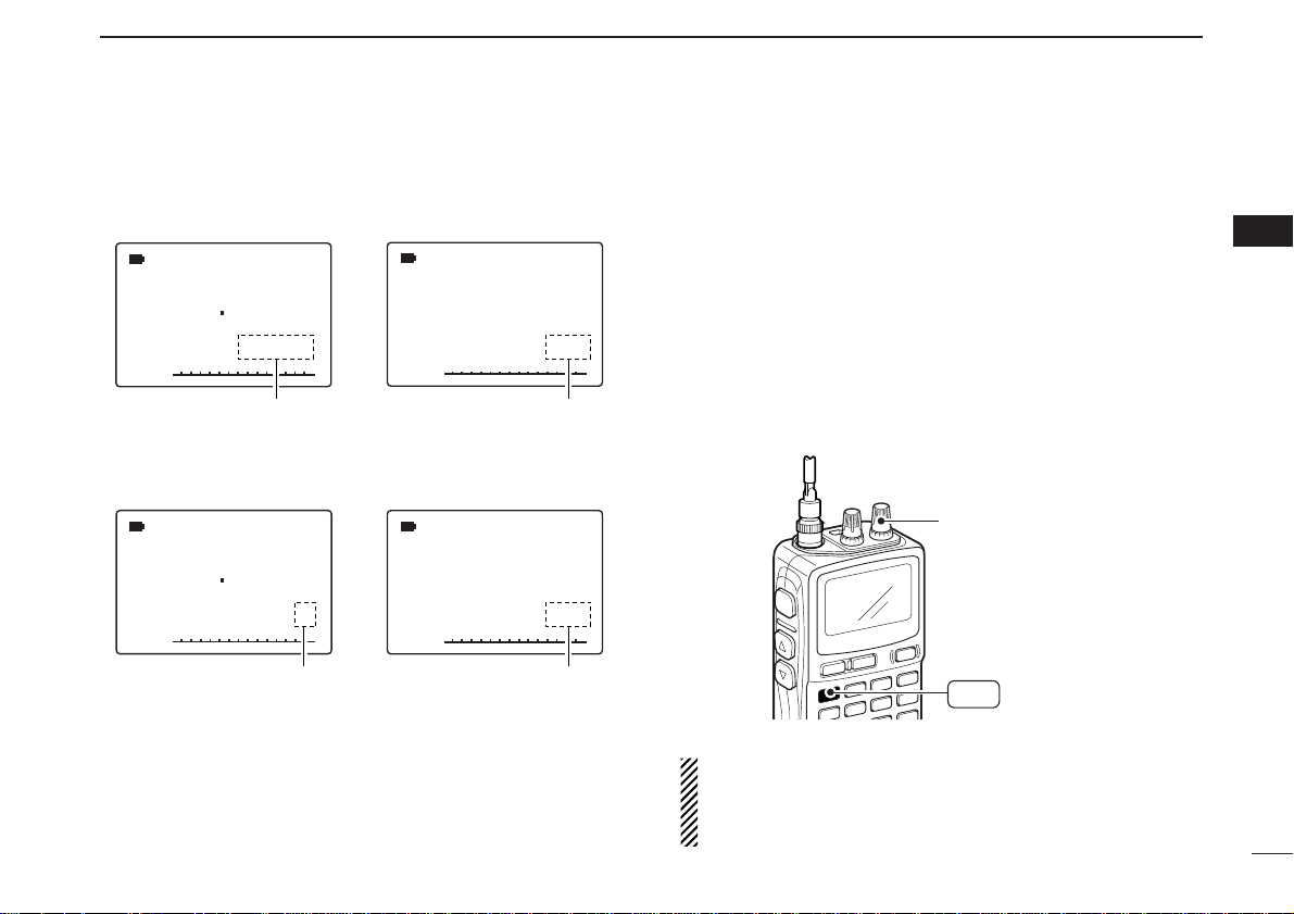
12
3
FREQUENCY AND CHANNEL SETTING
3
■ Operating band selection
The receiver can receive the AM broadcast, HF bands,
50 MHz, FM broadcast, VHF air, 144 MHz, 300 MHz,
400 MHz, 800 MHz,* 1200 MHz or 2400 MHz.
➥ In VFO mode, push [BAND] several times to select the de-
sired frequency band.
• If the other than VFO mode is selected, such as a memory/Pre-
Set/TV/Weather channel, push [VFO MHz] to select VFO mode
first, then push [BAND] to select the desired band.
➥ While pushing and holding [BAND], rotating [R-DIAL] also
selects frequency band.
Available frequency bands are different depending on version. See the specification for details.
*Some frequency ranges are prohibited for the USA ver-
sion due to local regulation.
√
MODE
ANL
AFCTSQL
WFM
76 000
PSKIP
-DUP
√
µ
MODE
ANL
AFCTSQL
FM
146 100
PSKIP
-DUP
001
0
√
MODE
ANL
AFCTSQL
WFM
2 ch
PSKIP
-DUP
TV
√
MODE
ANL
AFCTSQL
FM
1
PSKIP
-DUP
WX
“µ ” and memory channel
number appear.
• PreSet channel indication
• TV channel indication
• Weather channel indication
(USA version only)
• Memory mode indication
PreSet channel number appears.
“TV” indication appears.
“WX” indication appears.
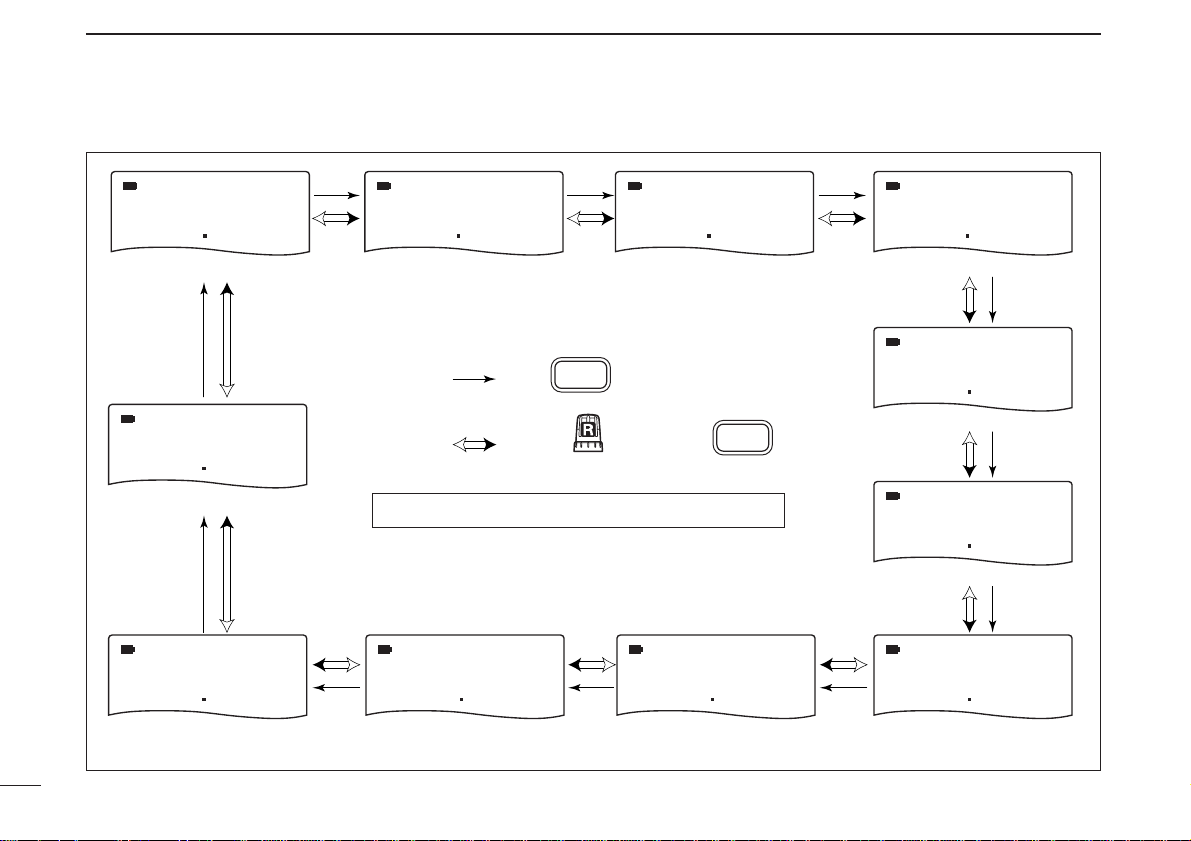
13
3
FREQUENCY AND CHANNEL SETTING
• Available frequency bands
MODE
AM
MODE
AM
MODE
FM
1620 5 000 51 000 76 000
AM broadcast band HF band 50 MHz band
BAND
MODE
FM
MODE
FM
2425 000
2400 MHz band
MODE
FM
: Push
: Rotating while pushing
Initial frequencies shown will differ according to version.
MODE
FM
1295 000
800 MHz band 400 MHz band
BAND
MODE
WFM
FM broadcast band
MODE
AM
118 000
VHF air band
MODE
FM
146 010
144 MHz band
MODE
AM
370 000440 000800 000
300 MHz band1200 MHz band
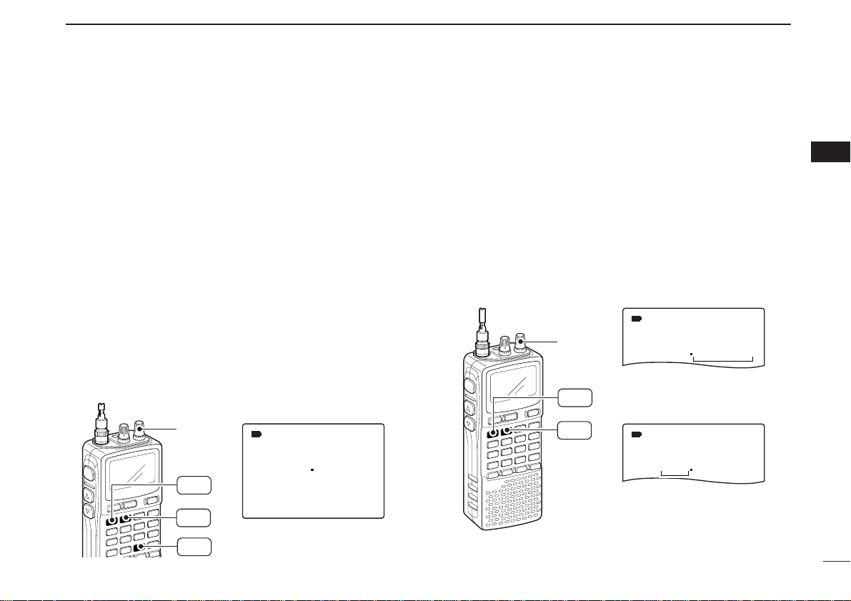
14
3
FREQUENCY AND CHANNEL SETTING
3
■ Setting a tuning step
The tuning step can be selected for each frequency band independently, however, the tuning steps, 8.33 kHz and 9 kHz,
only appear when setting the tuning step for the VHF air band
and AM broadcast band, respectively. The following tuning
steps are available for the IC-R20.
• 0.01 kHz • 0.1 kHz • 1.0 kHz • 5.0 kHz • 6.25 kHz
• 8.33 kHz* • 9.0 kHz* • 10.0 kHz • 12.5 kHz • 15.0 kHz
• 20.0 kHz • 25.0 kHz • 30.0 kHz • 50.0 kHz • 100.0 kHz
* Available for some frequency band only.
DD
Tuning step selection
qPush [VFO MHz] to select VFO mode, if necessary.
wPush [BAND] to select the desired frequency band.
•Or, while pushing and holding [BAND], rotate [R-DIAL] to select
the desired frequency band.
e Push [9 TS] for 1 sec. to enter tuning step selecting condition.
rRotate [R-DIAL] to select the desired tuning step.
tPush [9 TS] to return to VFO mode.
■ Setting a frequency
DD
Using the dial
qPush [VFO MHz] to select VFO mode, if necessary.
wSelect the desired frequency band with [BAND].
•Or, while pushing and holding [BAND], rotate [R-DIAL] to select
the desired frequency band.
eRotate [R-DIAL] to select the desired frequency.
• The frequency changes according to the preset tuning steps.
See the left section for setting the tuning step.
• Push [VFO MHz] for 1 sec. then rotate [R-DIAL] to change the
frequency in 1 MHz steps, or push for 1 sec. again then rotate
[R-DIAL] to change the frequency in 10 MHz steps. (Each push
for 1 sec. toggles 1 MHz or 10 MHz tuning steps.)
FM
MODE
146 010
00
FM
MODE
146 010
00
[R-DIAL] changes the frequency according to the selected tuning step.
While pushing [
VFO MHz
],
[R-DIAL] changes the frequency in 1 MHz steps (default).
[R-DIAL]
BAND
VFO
MHz
SET TS:5.0kHz
√
MODE
ANL
AFCTSQL
FM
146 010
PSKIP
-DUP
5 kHz tuning step
[R-DIAL]
TS
9
BAND
VFO
MHz
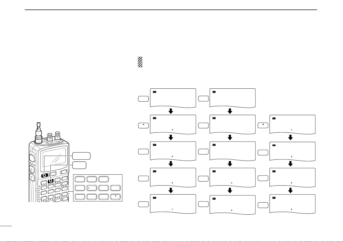
15
3
FREQUENCY AND CHANNEL SETTING
DD
Using the keypad
The frequency can be directly set via numeral
keys.
• When editing a frequency outside of the frequency range, the previously displayed frequency
is automatically recalled after editing last digit.
qPush [VFO MHz] to select VFO mode, if
necessary.
w Enter the desired frequency via the keypad.
• Direct input can be set until 1 kHz digit, rotate
[R-DIAL] to set below 1 kHz frequency after
set tuning steps, if necessary. (See the previous page for setting the tuning step.)
123
4560
789
LOCK
AFC
DUALWATCH
VFO
MHz
Pushing [VFO MHz] omits the entry of 100 kHz and below, when you want to
edit to these digits “0.” Push [DUALWATCH] to cancel the entry.
• Editting to 0.820 MHz • Editting to 1260 MHz • Changing 100 kHz
and below.
MODE
AFC
0
AM
000 010
MODE
1
FM
1 000
Editting
1260.000 MHz
to 1260.240 MHz
LOCK
MODE
AM
000 010
MODE
2
FM
12 000
MODE
LOCK
1260 240
FM
MODE
8
2
0
AM
000 8 84
MODE
AM
000 824
MODE
AM
000 820
MODE
6
MODE
AFC
0
1260 000
MODE
VFO
MHz
1260 000
FM
126 000
FM
FM
MODE
2
1260 2 40
MODE
4
1260 240
MODE
AFC
0
1260 240
FM
FM
FM
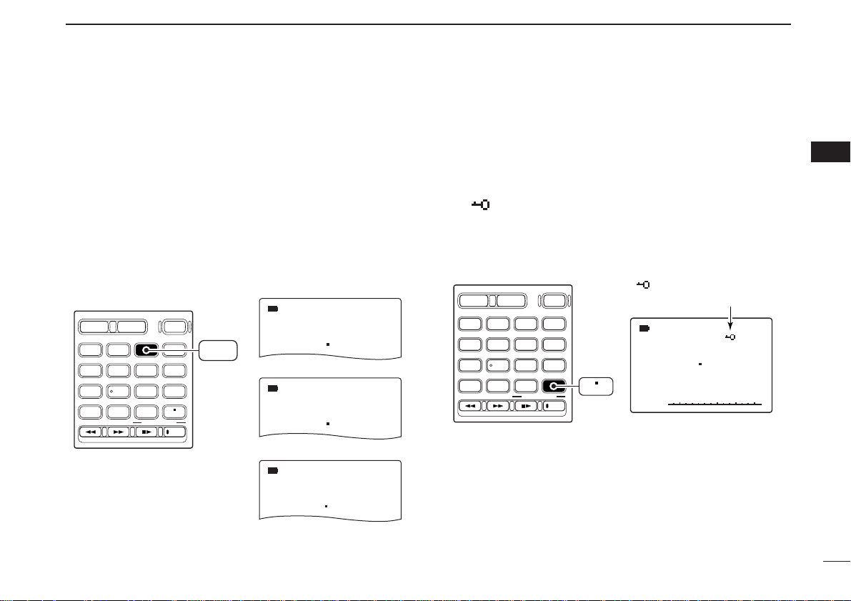
16
3
FREQUENCY AND CHANNEL SETTING
3
■ Receive mode selection
Receive modes are determined by the physical properties of
the radio signals. The receiver has 6 receive modes: FM,
WFM, AM, LSB, USB and CW modes. The mode selection is
stored independently in each band and memory channels.
Typically, AM mode is used for the AM broadcast stations
(0.495–1.620 MHz) and VHF air band (118–135.995 MHz),
and WFM is used for FM broadcast stations (76–107.9 MHz).
➥ Push [MODE SCAN] momentarily several times to select
the desired receive mode.
■ Lock function
To prevent accidental frequency changes and unnecessary
function access, use the lock function.
➥ Push [• LOCK] for 1 sec. to turn the lock function ON and
OFF.
•“ ” appears while the lock function is activated.
• The squelch control and volume control can be used while the
lock function is in use with default setting. Either or both the
squelch control and volume control can also be locked in set
mode. (p. 49)
√
MODE
ANL
AFCTSQL
FM
146 010
PSKIP
-DUP
DIAL.SEL SWEEP CENTER
T-SCAN SKIP M.N
TONE SET TS
ATT RF GAIN
IC Recorder
123
4560
789
BAND
DUALWATCH
MAIN/SUB
POWER
VFO
MHz
MODE
SCANMRS.MW
SCOPE
LOCK
REC
AFC
“ ” appears while the
lock function is in use.
LOCK
DUALWATCH
BAND
DIAL.SEL SWEEP CENTER
123
T-SCAN SKIP M.N
4560
TONE SET TS
789
ATT RF GAIN
MODE
FM
146 010
FM mode
MODE
AM
118 000
AM mode
MODE
WFM
76 000
WFM mode
PSKIP
PSKIP
PSKIP
VFO
MHz
MAIN/SUB
POWER
MODE
SCANMRS.MW
SCOPE
LOCK
IC Recorder
MODE
SCAN
AFC
REC
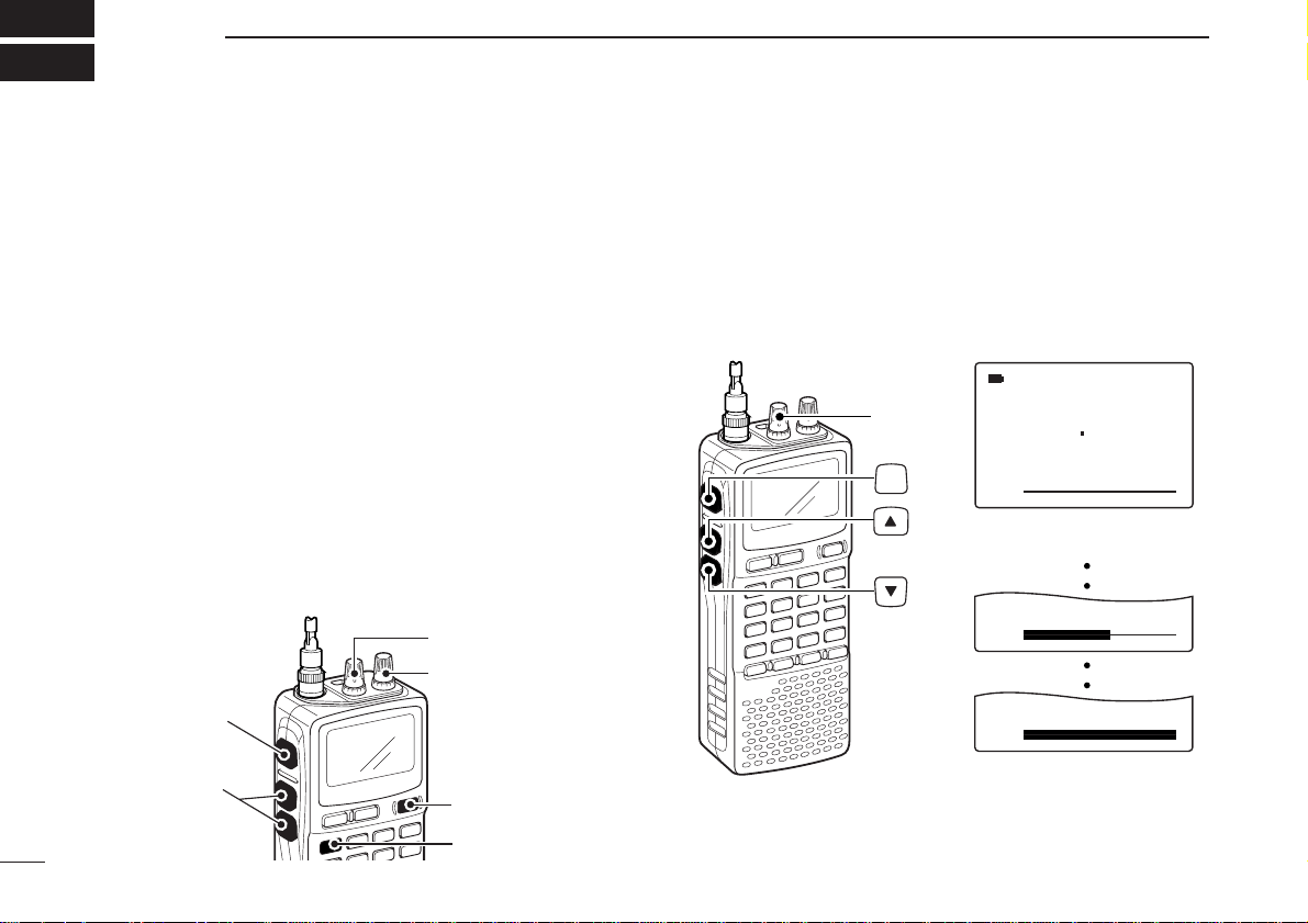
17
BASIC OPERATION
4
■ Receiving
Make sure charged battery pack (BP-206) or brand new alkaline batteries are installed (p. 8).
qPush [POWER] for 1 sec. to turn power ON.
wRotate [L-DIAL] (or push [YY] or [ZZ]) to set the desired
audio level.
• The frequency display shows the volume level while setting. See
the section at right for details.
eSet the receiving frequency. (p. 14)
rSet the squelch level. (p. 18)
• While pushing [SQL], rotate [R-DIAL].
• The first click of [R-DIAL] indicates the current squelch level.
•“LEVEL 1” is loose squelch and “LEVEL 9” is tight squelch.
• “AUTO” indicates automatic level adjustment with a noise pulse
count system.
• Push and hold [SQL] to open the squelch manually.
tWhen a signal is received:
• Squelch opens and audio is emitted.
•The S-meter shows the relative signal strength level.
■ Setting audio volume
The audio level can be adjusted through 39 levels.
➥ Push and hold [SQL], rotate [L-DIAL] (or p
ush [YY] or [ZZ])
to adjust the audio level.
• While using
[YY]/[ZZ]
, pushing and holding either key change the
audio level continuously.
• The display shows the volume level while setting.
√
MODE
ANL
AFCTSQL
FM
VOL
146 010
PSKIP
-DUP
√
VOL
√
VOL
[L-DIAL]
Minimum setting
(no audio)
Maximum setting
SQL
q [POWER]
e Set frequency
r Set squelch level
w Set audio level
w Set audio level
e Select band
r Push for setting
the squelch
(Push to monitor)
Loading…
Время на прочтение7 мин
Количество просмотров9.9K

Привет, люди будущего! Это Антон Комаров — автор команды спецпроектов МТС Диджитал. В прошлом посте я рассказывал, как сделать CI-V-кабель для управления приемником Icom IC-R20, и упоминал замечательный аппарат Icom IC-R20. Сегодня поделюсь с вами опытом его эксплуатации и расскажу, почему одни радиолюбители от него в восторге, а другие смотрят на него свысока. Поехали!
Внешний вид

Icom IC-R20 довольно крупный, его размеры — 60×142×34,8 мм. Но весит он немного — всего 320 г. Экран монохромный, жидкокристаллический с подсветкой зеленого цвета, занимает примерно треть передней панели устройства. Остальное делят между собой клавиатура и динамик.
На верхнем торце расположен стандартный 50-омный BNC-F-разъем для подключения внешней антенны. В комплекте есть телескопическая антенна, которая может складываться на 180 градусов. Это удобно для транспортировки — правда, уже спустя 15–20 циклов сборки приходится подтягивать болтики. К разъему можно без проблем подключить любую внешнюю антенну.

Также на верхней части устройства есть две крутилки DIAL, обозначенные как L и R. Их функции можно переназначить в настройках, но по умолчанию одна регулирует громкость, а другая служит для управления частотой.

На левой грани устройства — три прорезиненные кнопки. Верхняя отвечает за мониторинг. Пока вы удерживаете ее нажатой, из динамика будет слышен эфир на выбранной частоте, даже если там нет полезного сигнала. Две кнопки ниже могут с одинаковым успехом работать на изменение громкости или частоты.

На правой грани, за резиновыми заглушками, расположен совмещенный вход для наушников/CI-V, разъем для подключения блока питания и отдельный вход Mini-USB. Любопытно, что аудиоразъем может использоваться еще и в качестве антенного. Это нужно для лучшего приема вещательных FM-станций, когда возможностей встроенной магнитной антенны недостаточно.

На задней стороне расположен батарейный отсек. По умолчанию в него устанавливается перезаряжаемый Li-Ion-аккумулятор BP-206, точно такой же, как и в Icom IC-R3. Но главная фишка в том, что если батарейка села и у вас нет возможности ее зарядить, то при помощи специальной пластиковой вставки вы можете заменить ее на три обычных АА (LR6) батарейки или аккумулятора. Это особенно актуально для тех, кто много времени проводит на природе. Полного заряда хватит максимум на 11 часов, но при условии одновременного приема только одной частоты. Об этой особенности я расскажу чуть позже.

Для ношения на поясе в комплекте идет простая клипса MB-98, такая же, как и у большинства современных портативных раций. Она достаточно удобная, но у Icom есть чуть более интересный вариант этого аксессуара — поворотная быстросъемная клипса MB-86. Она позволяет легко снимать и вешать радиосканнер на пояс без необходимости отсоединения зажима.
Опционально можно докупить зарядный стакан BC-156 и чехол LC-158. Первый решает вопрос с тем, что на ровной поверхности сканер достаточно неустойчив, и помогает заряжать его, не дергая постоянно резиновую заглушку на разъеме DC. Радиосканер сам по себе довольно прочный и прошел испытания, эквивалентные военным MIL-STD 810 (C, D, E, F). При этом у него нет официального рейтинга защиты от пыли и влаги. Так что в полевых условиях его нужно дополнительно защищать при помощи чехла.
Технические характеристики
Приемный тракт
Аппаратная часть Icom IC-R20 весьма интересна. Этот радиоприемник способен принимать сигналы в очень широком диапазоне частот: 150 кГц — 3 304.999 МГц. В американской версии по требованиям законодательства вырезан спектр 800 МГц, предназначенный для мобильной связи.
Самое интересное, что аппарат может принимать две частоты одновременно. Кто-то скажет, что так может делать любой китайский трансивер за 20 долларов. Это верно, но внутри него будет простейший приемный тракт на микросхеме прямого усиления. Прием двух частот одновременно реализуется быстрым переключением между ними. То есть когда у вас есть полезный сигнал на одной частоте, то на другой он уже не будет приниматься.

Icom IC-R20 использует полностью другой подход. Внутри него фактически не один, а целых два приемных тракта. Это позволяет по-настоящему принимать две частоты в одно и то же время. Вместо прямого усиления используется супергетеродин с тройным преобразованием. Следующие частоты задействованы в качестве промежуточных:
-
266.7 МГц.
-
19.65 МГц.
-
450 кГц.
Этим достигается высокая избирательность и отличное подавление зеркальных каналов вкупе с меньшим количеством интермодуляционных искажений и лучшей стабильностью при приеме слабых сигналов. Тем не менее такая реализация имеет несколько важных особенностей и накладывает определенные ограничения. Когда вы включаете прием двух частот одновременно, это подключает второй тракт, что фактически вдвое увеличивает энергопотребление и снижает автономность.
Дополнительным ограничением становится то, что при работе двух приемных трактов нельзя использовать весь заявленный диапазон. Максимальная частота приема и модуляция при этом ограничены:
-
первый тракт (VFO A): 150 кГц — 469.999 МГц (LSB / USB / CW / AM / FM / WFM);
-
второй тракт (VFO B): 118 МГц — 174.999 МГц и 330 МГц — 1 304.999 МГц (AM / FM / WFM).
То есть в режиме приема двух частот одновременно нельзя выбрать диапазон выше 1 304.999 МГц. В большинстве случаев это и не нужно, так что не стоит это рассматривать как недостаток. Если же второй радиотракт отключить, то становится доступен весь заявленный диапазон.
Еще одна особенность Icom IC-R20 — наличие встроенного аттенюатора на 20 дБ. Это требуется в ряде случаев, включая прием сильных сигналов для защиты цепей от перегрузки или для повышения разборчивости слабых сигналов на фоне мощных помех.
Сканирование
Переходим к одной из самых сильных сторон этого приемника. Он сканирует эфир со скоростью аж 100 каналов в секунду в режиме VFO. Если работа ведется по сохраненным в памяти каналам (MR), то скорость будет примерно 30 каналов/с. Это втрое выше, чем у того же Icom IC-R5.
Отдельно стоит отметить гибкость настройки параметров. Девайс позволяет сканировать:
-
все частоты во всех доступных диапазонах приема;
-
все частоты в границах одного выбранного диапазона;
-
все частоты в границах произвольного диапазона между двумя заданными пользователем частотами;
-
последовательное сканирование всех частот в заданных банках памяти;
-
последовательное сканирование всех частот в заданных банках памяти за исключением тех, которые помечены как SKIP;
-
последовательное сканирование всех ранее не найденных частот, кроме тех, которые помечены как SKIP.
Пожалуй, самая интересная фишка — автоматическое сохранение всех найденных частот в память. Это упрощает поиск и дает возможность потом изучить каждую обнаруженную частоту. А при необходимости еще и записать принятые сигналы на цифровой диктофон.
Память
Сразу упомяну о том, что этот радиосканер выпущен в 2006 году и производился до 2014 года. Всего в нем помещалось 1 250 каналов, которые были поделены на три сегмента:
-
1 000 обычных;
-
50 пользовательских, задающих границы диапазона для сканирования;
-
200 каналов, которые использовала только функция автосохранения при сканировании.

Помимо этого, IC-R20 оснащался 32 Мб флеш-памяти для записи сигналов на цифровой диктофон. В зависимости от выбранного качества — высокое, среднее или низкое — можно было записать до 260 минут, разбитых на 32 трека соответственно. Функция эта наиболее востребована при приеме сигналов со спутников, время пролета которых ограничено.
Так, например, пролет МКС занимает около 10 минут. В дни, когда с борта станции ведется трансляция изображений в формате SSTV, радиолюбители со всего мира пробуют их принять и декодировать. Если в этот момент у вас под рукой есть Icom IC-R20, можно просто включить запись сигнала одной кнопкой, а декодировать уже позднее, подключив к компьютеру.
Увы, но существенную ложку дегтя в эту бочку меда добавляет проприетарный формат записи. При попытке скачивания файлов с помощью родного софта вы получаете набор треков в ICW. Благо в сети есть бесплатная программа-конвертер, которая преобразует ICW-треки в обычные WAV-файлы. В целом, если использовать высокое качество записи, никаких проблем с декодированием сигналов SSTV не возникает.
Прочие фичи

Не могу не упомянуть, что в Icom IC-R20 есть примитивный, но все же спектроскоп. Сейчас, во времена расцвета SDR-приемников, этим сложно кого-то удивить, но 18 лет назад не у каждого приемника была возможность обнаружить активность на соседних частотах.
Работало это так: вы выбирали диапазон сканирования (на фотографии — 25 кГц), а приемник без звука быстро «пробегал» по нему с определенным шагом и фиксировал уровень сигнала, одновременно отрисовывая его на экране. Так формировалась картинка, где отчетливо показывались пиковые значения сигналов. Потом можно было настроиться на них и поочередно их прослушать. Конечно, это давало только очень грубое представление о том, что происходит на соседних частотах. Но это лучше, чем ничего.
Мнения радиолюбителей
Icom IC-R20 никого не оставил равнодушным. Те, кому довелось использовать этот радиосканер, отмечают его удобство и высокую скорость сканирования. 100 каналов в секунду — это было невероятно быстро для 2006 года! Конечно, последовавшая за IC-R20 модель IC-R30 увеличила этот показатель вдвое, но такое улучшение вряд ли было реально нужно.
Единственный недостаток — малый объем памяти. С учетом высокой стоимости девайса это вызывало недоумение: раз в то время уже вполне себе продавались флешки на 512 Мб, можно было воткнуть хотя бы 128 Мб. Наверное, этому есть какое-то разумное объяснение, но оно вряд ли устроило бы радиолюбителя, который отсчитал 550 долларов за это чудо техники.
Ближайшим конкурентом Icom IC-R20 был сканирующий радиоприемник AOR AR-8200. Он выпускался в трех вариантах: mk1, mk2 и mk3. Каждая следующая версия значительно расширяла возможности приемника, но все равно по некоторым параметрам не могла догнать конкурента от Icom.
Тем не менее большинство радиолюбителей отмечает, что качество звука AOR значительно выше, равно как и эргономика управления. Хотя, на мой взгляд, это дело привычки: даже слабые сигналы вполне разборчивы, а для лучшего качества можно подключить внешний динамик или наушник.
Еще одним конкурентом, кроме AOR AR-8200, был радиосканер Alinco DJ-X2000. Но по техническим характеристикам он значительно скромнее. Скорость сканирования всего 30 каналов/с в режиме VFO, а при переключении в MR так и вообще падала до 7 каналов/с. Диктофон тоже вмещал всего несколько минут записи.
Тем не менее у Alinco есть своя изюминка — встроенный частотомер. Он очень быстро определяет частоту ближайшего источника излучения и мгновенно на нее настраивается. В некоторых случаях это очень полезно. Увы, но девайсы Alinco так и не стали популярными, включая российских пользователей. Да и достать их сложнее, чем тот же Icom или AOR.
Что в итоге
Icom IC-R20 через 10 лет с момента завершения выпуска остается одним из самых удобных и функциональных радиосканеров. Даже с учетом некоторых недостатков, таких как малый объем встроенной памяти и проприетарный формат записи, он предлагал отличный набор возможностей: быстрое сканирование, широкий диапазон частот, цифровой диктофон и даже простой спектроскоп.
Основным его недостатком для 2024 года может показаться полное отсутствие поддержки цифровых видов связи. Несмотря на это, его впечатляющие характеристики, наличие двух приемных трактов и возможность удаленного управления позволяют ему оставаться актуальным. Это устройство стало своеобразным эталоном для многих радиолюбителей.
А вы когда-нибудь пользовались Icom IC-R20? Если да, расскажите об этом в комментариях.