

Cooker
K1G21/R
Installation and use
Êóõoííaя плита
Установка и пользование
Aragaz
Instalare ºi utilizare
K1G21S/R

Cooker with gas oven and gas grill
Instructions for installation and use
3
Плита с газовой духовкой и газовым грилем
Инструкции по установке и эксплуатации
Aragaz cu cuptor pe gaz ºi grill pe gaz
Instrucþiuni pentru instalare ºi utilizare
14
24

Important safety warnings
T o maintain the EFFICIENCY and SAFETY of this appliance, we recommend:
• call only the Service Centers authorized by the manufacturer
• always use original Spare Parts
1 This appliance is intended for nonprofessional use within the home.
2 These instructions are only for those countries whose symbols appear in the
booklet and on the serial no. plate of the appliance.
3 This owner’s man ual is for a class 1 appliance (insulated) or
class 2, subclass 1 appliances (installed between two cabinets.
4 Before using your appliance, read the instructions in this owner’s manual carefully
since it provides all the information you need to ensure safe installation, use and
maintenance. Always keep this owner’s manual close to hand since you may
need to refer to it in the future.
5 When you have removed the packing, check that the appliance is not damaged.
If you have any doubts, do not use the appliance and contact your nearest
Ariston Service Centre. Never leave the packing components (plastic bags,
polystyrene foam, nails, etc.) within the reach of children since they are a source
of potential danger.
6 The appliance must be installed only by a qualified technician in
compliance with the instructions provided. The manufacturer
declines all liability for improper installation, which may result in
personal injury and damage to property.
7 The electrical safety of this appliance can only be guaranteed if
it is correctly and efficiently earthed, in compliance with regulations on electrical safety. Alwa ys ensure that the earthing is efficient. If y ou hav e any doubts, contact a qualified technician to
check the system. The manufacturer declines all liability f or damage resulting from a system which has not been earthed.
8 Before plugging the appliance into the mains, check that the
specifications indicated on the date plate (on the appliance and/
or packaging) correspond with those of the electrical and gas
systems in your home.
9 Check that the electrical capacity of the system and sockets will
support the maximum power of the appliance, as indicated on
the data plate. If you ha ve an y doubts, contact a qualified technician.
10 An omnipolar switch with a contact opening of at least 3 mm or
more is required for installation.
11 If the socket and appliance plug are not compatible, have the
socket replaced with a suitable model b y a qualified technician,
who should also check that the cross-section of the socket cable is sufficient for the power absorbed by the appliance. The
use of adaptors, multiple sock ets and/or extensions , is not recommended. If their use cannot be avoided, remember to use
only single or multiple adapters and extensions which comply
with current safety regulations. In these cases, never exceed
the maximum current capacity indicated on the individual adaptor or extension and the maximum pow er indicated on the multiple adapter.
12 Do not leave the appliance plugged in if it is not in use. Switch
off the main switch and gas supply when you are not using the
appliance.
13 The openings and slots used for ventilation and heat dispersion
must nev er be covered.
14 The user must not replace the supply cable of this appliance. Always contact an
after-sales service centre which has been authorised by the manufacturer if the
cable has been damaged or needs replacement.
15 This appliance must be used for the purpose for which it was expressly designed.
Any other use (e.g. heating rooms) is considered to be improper and conse-
16 A number of fundamental rules must be followed when using electrical appliances.
17 Always unplug the appliance from the mains or switch off the
18 If you are no longer using an appliance of this type, remember
19 To avoid accidental spillage do not use cookware with uneven
20 Never use flammable liquids such as alcohol or gasoline, etc.
21 When using small electric appliances near the hob, keep the
22 Make sure the knobs are in the “•”/”¡” position when the appli-
23 When the appliance is in use, the heating elements and some
24 Gas appliances require regular air exc hange to ensure trou-
25 The glass top (only on certain models) can shatter if it is over-
26 If the cooker is placed on a pedestal, take the necessary
27 Warning: never place hot containers or items and
quently dangerous. The manufacturer declines all liability for damage resulting
from improper and irresponsible use.
The following are of particular importance:
• Do not touch the appliance when your hands or feet are
wet.
• Do not use the appliance barefooted.
• Do not use extensions, but if they are necessary, caution
must be ex ercised.
• Never pull the power supply cable or the appliance to unplug the appliance plug from the mains.
• Never lea ve the appliance exposed to atmospheric agents
(rain, sun etc.)
• Do not allow children or persons who are not familiar with
the appliance to use it, without supervision.
main switch before cleaning or carrying out maintenance.
to make it unserviceable by unplugging the appliance from the
mains and cutting the supply cable. Also make all potentially
dangerous parts of the appliance safe, above all for children
who could play with the appliance.
or deformed bottoms on the burners. Turn the handles of pots
and pans inwards to avoid knoc king them ov er accidentally.
near the appliance when it is in use.
supply cord away from the hot parts.
ance is not in use.
parts of the oven door become extremely hot. Make sure you
don’t touch them and keep children well aw a y.
ble-free performance. When installing the cooker , follow the
instructions provided in the paragraph on “P ositioning” the
appliance.
heated. Therefore , all of the burners or hot plates must be turned
off before the top is closed.
precautions to prevent the same from sliding off the pedestal
itself.
flammable materials inside the dishwarmer drawer .
3

Installation
All instruction on the following pages must be carried out
by a competent person (corgi registered) in compliance
with gas safety (installation and use) regulation 1984.
Important: disconnect the cooker from the electrycity
and gas supply when any adjustment, etc.
Positioning your appliance
Important: this appliance may be installed and used only
in permanently ventilated rooms in compliance with current
directives. The following precautions should be taken:
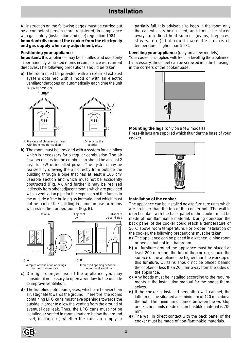
a) The room must be provided with an external exhaust
system obtained with a hood or with an electric
ventilator that goes on automatically each time the unit
is switched on.
In the case of chimneys or flues Directly to the
with branches (for cookers) exterior
b) The room must be provided with a system for air inflow
which is necessary for a regular combustion. The air
flow necessary for the combustion should be at least 2
m3/h for kW of installed power. The system may be
realized by drawing the air directly from outside the
building through a pipe that has at least a 100 cm
useable section and which must not be accidently
obstructed (Fig. A). And further it may be realized
indirectly from other adjacent rooms which are provided
with a ventilation pipe for the e xpulsion of the fumes to
the outside of the building as foresaid, and which must
not be part of the building in common use or rooms
with risk of fire, or bedrooms (Fig. B).
Detail A Adjacent Room to
room be ventilated
A
Fig. A Fig. B
Examples of ventilation openings Increased opening between
for the comburent air the door and and floor
c) During prolonged use of the appliance you may
consider it necessary to open a window to the outside
to improve ventilation.
d) The liquefied petroleum gases, which are heavier than
air, stagnate tow ards the ground. Theref ore, the rooms
containing LPG cans must have openings tow ards the
outside in order to allow the venting from the ground of
eventual gas leak. Thus, the LPG cans must not be
installed or settled in rooms that are below the ground
level, (cellar, etc.) whether the cans are empty or
partially full. It is advisable to keep in the room only
the can which is being used, and it must be placed
away from direct heat sources (ovens, fireplaces,
stoves, etc.) that could make the can reach
temperatures higher than 50°C.
Levelling your appliance (only on a fe w models)
Y our cook er is supplied with feet for le velling the appliance.
If necessary , these feet can be screwed into the housings
in the corners of the cooker base.
Mounting the legs (only on a few models)
Press-fit legs are supplied which fit under the base of your
cooker.
2
Installation of the cooker
The appliance can be installed next to furniture units which
are no taller than the top of the cooker hob. The wall in
direct contact with the back panel of the cooker must be
made of non-flammable material. During operation the
back panel of the cooker could reach a temperature of
50°C above room temperature. For proper installation of
the cooker, the following precautions must be taken:
a) The appliance can be placed in a kitchen, dining room
or bedsit, but not in a bathroom.
b) All furniture around the appliance must be placed at
least 200 mm from the top of the cooker, should the
surface of the appliance be higher than the worktop of
this furniture. Curtains should not be placed behind
the cooker or less than 200 mm awa y from the sides of
the appliance.
c) Any hoods must be installed according to the require-
ments in the installation manual for the hoods themselves.
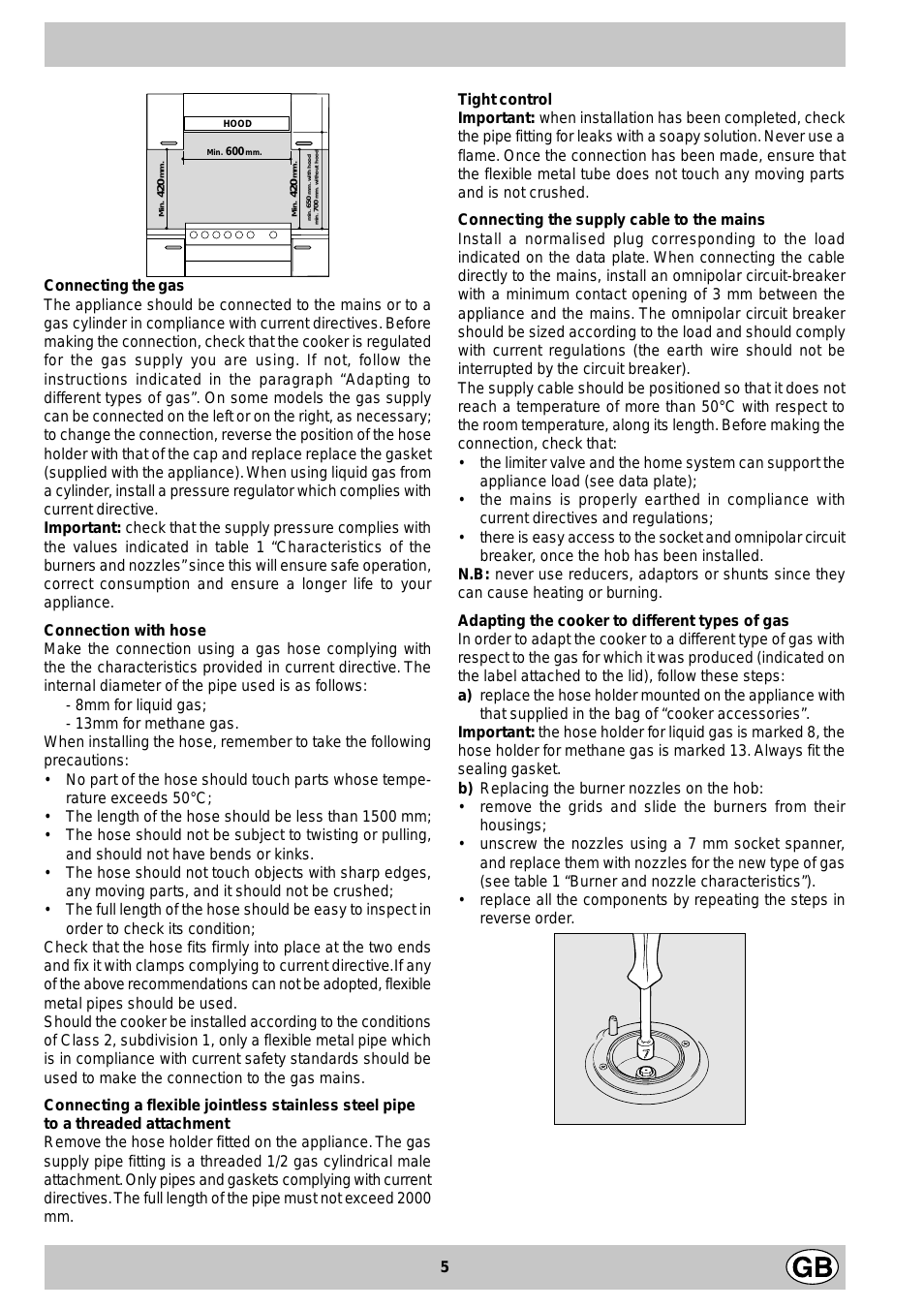
d) If the cooker is installed beneath a wall cabinet, the
latter must be situated at a minimum of 420 mm above
the hob. The minimum distance between the worktop
and kitchen units made of combustible material is 700
mm.
e) The wall in direct contact with the back panel of the
cooker must be made of non-flammable materials.
4

HOOD
Min. mm.
600
mm.
420
Min.
mm. with hood
420
650
Min. mm.
min.
mm. without hood
700
min.
Connecting the gas
The appliance should be connected to the mains or to a
gas cylinder in compliance with current directives. Bef ore
making the connection, check that the cooker is regulated
for the gas supply you are using. If not, follow the
instructions indicated in the paragraph “Adapting to
different types of gas”. On some models the gas supply
can be connected on the left or on the right, as necessary;
to change the connection, reverse the position of the hose
holder with that of the cap and replace replace the gasket
(supplied with the appliance). When using liquid gas from
a cylinder, install a pressure regulator which complies with
current directive.
Important: check that the supply pressure complies with
the values indicated in table 1 “Characteristics of the
burners and nozzles” since this will ensure saf e operation,
correct consumption and ensure a longer life to your
appliance.
Connection with hose
Make the connection using a gas hose complying with
the the characteristics provided in current directive. The
internal diameter of the pipe used is as follows:
— 8mm for liquid gas;
— 13mm for methane gas.
When installing the hose, remember to take the following
precautions:
• No part of the hose should touch parts whose tempe-
rature exceeds 50°C;
• The length of the hose should be less than 1500 mm;
• The hose should not be subject to twisting or pulling,
and should not have bends or kinks .
• The hose should not touch objects with sharp edges,
any moving parts, and it should not be crushed;
• The full length of the hose should be easy to inspect in
order to check its condition;
Check that the hose fits firmly into place at the two ends
and fix it with clamps complying to current directive.If any
of the above recommendations can not be adopted, fle xible
metal pipes should be used.
Should the cooker be installed according to the conditions
of Class 2, subdivision 1, only a flexible metal pipe which
is in compliance with current safety standards should be
used to make the connection to the gas mains.
Tight control
Important: when installation has been completed, check
the pipe fitting for leaks with a soapy solution. Ne ver use a
flame. Once the connection has been made, ensure that
the flexible metal tube does not touch any moving parts
and is not crushed.
Connecting the supply cable to the mains
Install a normalised plug corresponding to the load
indicated on the data plate. When connecting the cable
directly to the mains, install an omnipolar circuit-breaker
with a minimum contact opening of 3 mm between the
appliance and the mains. The omnipolar circuit breaker
should be sized according to the load and should comply
with current regulations (the earth wire should not be
interrupted by the circuit breaker).
The supply cable should be positioned so that it does not
reach a temperature of more than 50°C with respect to
the room temperature, along its length. Before making the
connection, check that:
• the limiter valve and the home system can support the
appliance load (see data plate);
• the mains is properly ear thed in compliance with
current directives and regulations;
• there is easy access to the socket and omnipolar circuit
breaker , once the hob has been installed.
N.B: never use reducers, adaptors or shunts since they
can cause heating or burning.
Adapting the cooker to different types of gas
In order to adapt the cooker to a different type of gas with
respect to the gas for which it was produced (indicated on
the label attached to the lid), follow these steps:
a) replace the hose holder mounted on the appliance with
that supplied in the bag of “cooker accessories”.
Important: the hose holder for liquid gas is marked 8, the
hose holder for methane gas is marked 13. Alwa ys fit the
sealing gasket.
b) Replacing the burner nozzles on the hob:
• remove the grids and slide the burners from their
housings;
• unscrew the nozzles using a 7 mm socket spanner,
and replace them with nozzles for the new type of gas
(see table 1 “Burner and nozzle characteristics”).
• replace all the components by repeating the steps in
reverse order.
Connecting a flexible jointless stainless steel pipe
to a threaded attachment
Remove the hose holder fitted on the appliance. The gas
supply pipe fitting is a threaded 1/2 gas cylindrical male
attachment. Only pipes and gask ets complying with current
directives. The full length of the pipe must not exceed 2000
mm.
5

c) Minimum regulation of the hob burners:
•
turn the tap to minimum;
• remove the knob and adjust the regulation screw , which
is positioned in or next to the tap pin, until the flame is
small but steady.
N.B.: in the case of liquid gas, the regulation screw
must be screwed in to the bottom.
• check that the flame does not turn off when you turn
the tap quickly from high to low.
d) Regulating the primary air of the burners:
The primary air of the burners requires no regulation.
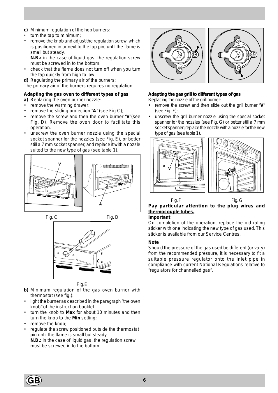
Adapting the gas oven to different types of gas
a) Replacing the oven burner nozzle:
• remove the warming drawer;
• remove the sliding protection “A” (see Fig.C);
• remove the screw and then the oven burner “V”(see
Fig. D). Remove the oven door to facilitate this
operation.
• unscrew the oven burner nozzle using the special
socket spanner for the nozzles (see Fig. E), or better
still a 7 mm socket spanner , and replace it with a nozzle
suited to the new type of gas (see table 1).
V
A
Fig. C Fig. D
Adapting the gas grill to different types of gas
Replacing the nozzle of the grill burner:
• remove the screw and then slide out the grill burner “V”
(see Fig. F);
• unscrew the grill burner nozzle using the special socket
spanner for the nozzles (see Fig. G) or better still a 7 mm
socket spanner; replace the nozzle with a nozzle f or the new
type of gas (see table 1).
I
Fig. F Fig. G
Pay particular attention to the plug wires and
thermocouple tubes.
Important
On completion of the operation, replace the old rating
sticker with one indicating the new type of gas used. This
sticker is av ailab le from our Service Centres.
Fig.E
b) Minimum regulation of the gas oven burner with
thermostat (see fig.):
• light the burner as described in the paragraph “the oven
knob” of the instruction booklet.
• tur n the knob to Max for about 10 minutes and then
turn the knob to the Min setting;
• remove the knob;
• regulate the screw positioned outside the thermostat
pin until the flame is small but steady.
N.B.: in the case of liquid gas, the regulation screw
must be screwed in to the bottom.
Note
Should the pressure of the gas used be different (or vary)
from the recommended pressure, it is necessary to fit a
suitable pressure regulator onto the inlet pipe in
compliance with current National Regulations relative to
“regulators for channelled gas”.
6

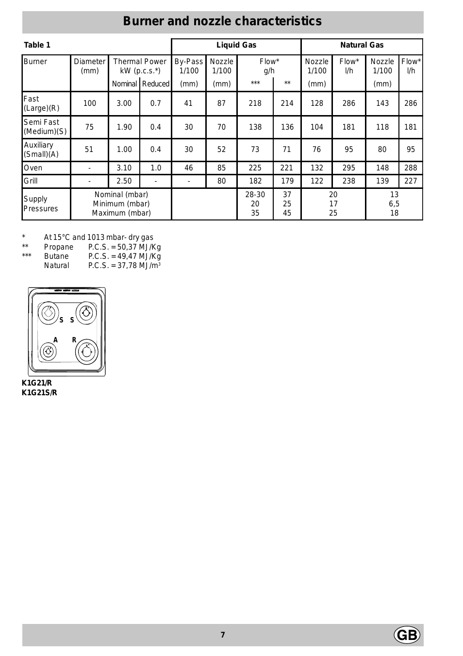
Burner and nozzle characteristics
Table 1 Liquid Gas Natural Gas
Burner Diameter
(mm)
Thermal Power
kW (p.c.s.*)
By-Pass
1/100
Nozzle
1/100
Flow*
g/h
Nozzle
1/100
Flow*
l/h
Nozzle
1/100
Flow*
l/h
Nominal Reduced (mm) (mm) *** ** (mm) (mm)
Fast
(Large)(R)
Semi Fast
(Medium)(S)
Auxiliary
(Small)(A)
100 3.00 0.7 41 87 218 214 128 286 143 286
75 1.90 0.4 30 70 138 136 104 181 118 181
51 1.00 0.4 30 52 73 71 76 95 80 95
Oven — 3.10 1.0 46 85 225 221 132 295 148 288
Grill — 2.50 — — 80 182 179 122 238 139 227
Supply
Pressures
Nominal (mbar)
Minimum (mbar)
Maximum (mbar)
28-30
20
35
37
25
45
20
17
25
13
6,5
18
* At 15°C and 1013 mbar- dry gas
** Propane P.C.S . = 50,37 MJ/Kg
*** Butane P.C.S . = 49,47 MJ/Kg
Natural P.C.S . = 37,78 MJ/m
3
K1G21/R
K1G21S/R
S
S
R
A
7

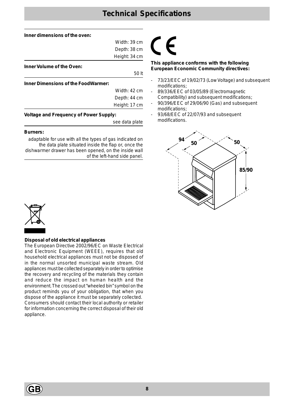
Technical Specifications
Inner dimensions of the oven:
Width: 39 cm
Depth: 38 cm
Height: 34 cm
Inner Volume of the Oven:
50 lt
Inner Dimensions of the FoodWarmer:
Width: 42 cm
Depth: 44 cm
Height: 17 cm
V olta ge and Frequency of Power Supply:
see data plate
Burners:
adaptable for use with all the types of gas indicated on
the data plate situated inside the flap or, once the
dishwarmer drawer has been opened, on the inside wall
of the left-hand side panel.
%
This appliance conforms with the following
European Economic Community directives:
— 73/23/EEC of 19/02/73 (Low V oltage) and subsequent
modifications;
— 89/336/EEC of 03/05/89 (Electromagnetic
Compatibility) and subsequent modifications;
— 90/396/EEC of 29/06/90 (Gas) and subsequent
modifications;
— 93/68/EEC of 22/07/93 and subsequent
modifications.
94
50
50
Disposal of old electrical appliances
The European Directive 2002/96/EC on Waste Electrical
and Electronic Equipment (WEEE), requires that old
household electrical appliances must not be disposed of
in the normal unsorted municipal waste stream. Old
appliances must be collected separately in order to optimise
the recovery and recycling of the materials they contain
and reduce the impact on human health and the
environment. The crossed out “wheeled bin” symbol on the
product reminds you of your obligation, that when you
dispose of the appliance it must be separately collected.
Consumers should contact their local authority or retailer
for information concerning the correct disposal of their old
appliance.
85/90
8
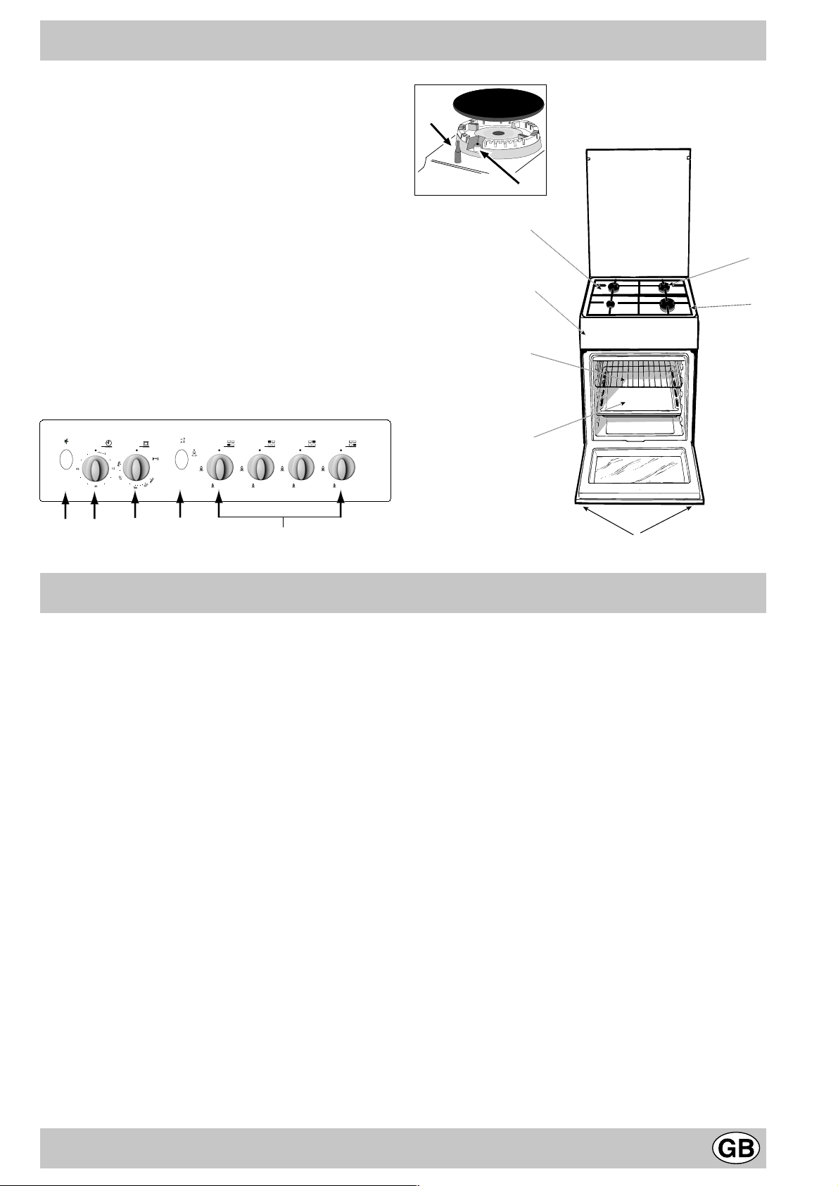
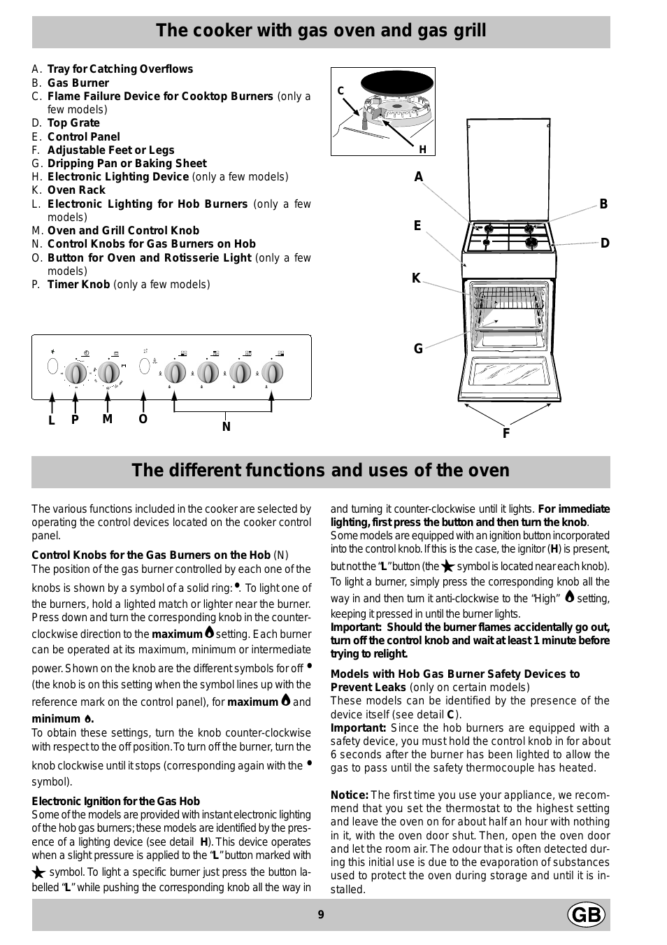
The cooker with gas oven and gas grill
A. T ra y for Catching Overflows
B. Gas Burner
C. Flame Failure Device for Cooktop Burners (only a
few models)
D. T op Grate
E. Control Panel
F. Adjustable Feet or Legs
G. Dripping Pan or Baking Sheet
H. Electronic Lighting Device (only a few models)
K. Oven Rack
L. Electronic Lighting for Hob Burners (only a few
models)
M. Oven and Grill Control Knob
N. Control Knobs for Gas Burners on Hob
O. Button for Oven and Rotisserie Light (only a few
models)
P. Timer Knob (only a few models)
C
H
M
P
L
O
N
The different functions and uses of the oven
The various functions included in the cooker are selected by
operating the control devices located on the cooker control
panel.
Control Knobs for the Gas Burners on the Hob (N)
The position of the gas burner controlled by each one of the
knobs is shown by a symbol of a solid ring:•. To light one of
the burners, hold a lighted match or lighter near the burner.
Press down and turn the corresponding knob in the counter-
clockwise direction to the maximum — setting. Each burner
can be operated at its maximum, minimum or intermediate
power . Sho wn on the knob are the different symbols for off •
(the knob is on this setting when the symbol lines up with the
reference mark on the control panel), for maximum — and
minimum +.
To obtain these settings, turn the knob counter-clockwise
with respect to the off position. T o turn off the burner, turn the
knob clockwise until it stops (corresponding again with the •
symbol).
Electronic Ignition for the Gas Hob
Some of the models are provided with instant electronic lighting
of the hob gas burners; these models are identified by the presence of a lighting device (see detail H). This device operates
when a slight pressure is applied to the “L” button marked with
symbol. To light a specific burner just press the button la-
1
belled “L” while pushing the corresponding knob all the way in
and turning it counter-clockwise until it lights. For immediate
lighting, first press the b utton and then turn the knob.
Some models are equipped with an ignition button incorporated
into the control knob. If this is the case, the ignitor (H) is present,
but not the “L” button (the 1 symbol is located near each knob).
To light a burner, simply press the corresponding knob all the
way in and then turn it anti-clockwise to the “High” — setting,
keeping it pressed in until the burner lights.
Important: Should the burner flames accidentally go out,
turn off the control knob and wait at least 1 minute before
trying to relight.
Models with Hob Gas Burner Safety Devices to
Prevent Leaks (only on certain models)
These models can be identified by the presence of the
device itself (see detail C).
Important: Since the hob burners are equipped with a
safety device , you must hold the control knob in f or about
6 seconds after the burner has been lighted to allow the
gas to pass until the safety thermocouple has heated.
Notice: The first time you use your appliance, we recommend that you set the thermostat to the highest setting
and leave the ov en on f or about half an hour with nothing
in it, with the oven door shut. Then, open the oven door
and let the room air. The odour that is often detected during this initial use is due to the evaporation of substances
used to protect the oven during storage and until it is installed.
9

Attention: Only use the bottom shelf of the oven when using
the rotisserie to cook (where present). F or all other types of
cooking, never use the bottom shelf and ne ver place anything
on the bottom of the oven when it is in operation because
this could damage the enamel. Always place your cookware
(dishes, aluminium foil, etc. etc.) on the grate provided with
the appliance inserted especially along the oven guides.
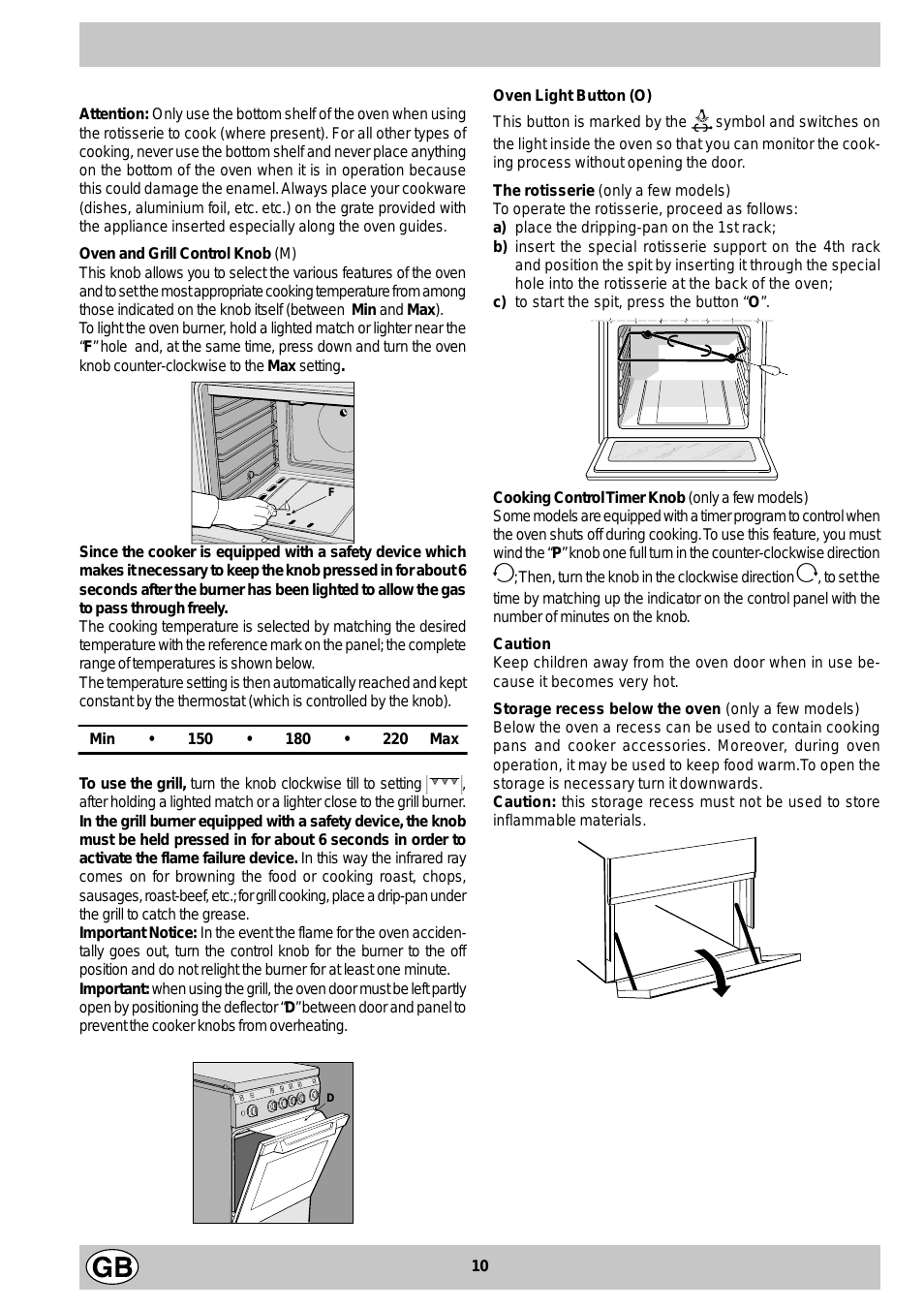
Oven and Grill Control Knob (M)
This knob allows you to select the v arious features of the ov en
and to set the most appropriate cooking temperature from among
those indicated on the knob itself (between Min and Max).
T o light the o ven burner , hold a lighted match or lighter near the
“F” hole and, at the same time, press down and turn the oven
knob counter-clockwise to the Max setting.
Oven Light Button (O)
This button is marked by the I symbol and switches on
the light inside the oven so that you can monitor the cook-
ing process without opening the door.
The rotisserie (only a few models)
To operate the rotisserie, proceed as follows:
a) place the dripping-pan on the 1st rack;
b) insert the special rotisserie suppor t on the 4th rack
and position the spit by inserting it through the special
hole into the rotisserie at the back of the oven;
c) to start the spit, press the button “O”.
F
Since the cooker is equipped with a safety device which
makes it necessary to keep the knob pressed in for about 6
seconds after the burner has been lighted to allow the gas
to pass through freely .
The cooking temperature is selected by matching the desired
temperature with the reference mark on the panel; the complete
range of temperatures is shown below .
The temperature setting is then automatically reached and kept
constant by the thermostat (which is controlled by the knob).
Min • 150 • 180 • 220 Max
To use the grill, turn the knob clockwise till to setting ,
after holding a lighted match or a lighter close to the grill burner.
In the grill burner equipped with a safety device, the knob
must be held pressed in for about 6 seconds in order to
activate the flame failure device. In this way the infrared ray
comes on for browning the food or cooking roast, chops,
sausages, roast-beef, etc.; for grill cooking, place a drip-pan under
the grill to catch the grease.
Important Notice: In the event the flame f or the oven accidentally goes out, turn the control knob for the burner to the off
position and do not relight the burner for at least one minute.
Important: when using the grill, the ov en door must be left partly
open by positioning the deflector “D” between door and panel to
prevent the cooker knobs from overheating.
Cooking Control Timer Knob (only a fe w models)
Some models are equipped with a timer program to control when
the oven shuts off during cooking. T o use this f eature, you m ust
wind the “P” knob one full turn in the counter-clockwise direction
#; Then, turn the knob in the clockwise direction «, to set the
time by matching up the indicator on the control panel with the
number of minutes on the knob.
Caution
Keep children away from the oven door when in use because it becomes very hot.
Storage recess below the oven (only a few models)
Below the oven a recess can be used to contain cooking
pans and cooker accessories. Moreover, during oven
operation, it may be used to keep f ood w arm.To open the
storage is necessary turn it downwards.
Caution: this storage recess must not be used to store
inflammable materials.
D
10

Practical advice for burner use
In order to get the maximum yield it is important to
remember the following:
• Use appropriate cookware for each burner (see table)
so as to avoid flames overshooting the edges.
• At boiling point turn the knob to minimum.
• Use cookware with lids.
• Always use cookware with flat bottoms.
Cooking advice
Burner ø Cookware diameter (cm)
Fast (R) 24 — 26
Semi Fast (S) 16 — 20
Auxiliary (A) 10 — 1 4
The oven offers a wide range of alternatives which allow
you to cook any type of food in the best possib le wa y . With
time you will learn to make the best use of this versatile
cooking appliance and the following directions are only a
guideline which may be varied according to your own personal experience.
Baking cakes
The oven should alwa ys be warm before putting in cak es
wait till the end of preheating (about 10-15 min.). Cakebaking temperatures are normally around 160°C/200°C.
Do not open the oven door during the baking process as
this could cause the cake to sink.In general:
Pastry is too dry
Increase the tem perat ure by 10°C and reduce the
cooking time.
Pastry dropped
Use less liquid or lower the t emper atur e by 10 °C.
Pastry is too dark on top
Place it on a lower r ack, lowe r the tempe rature , and
increase the c ooking time.
Cooking fish and meat
When cooking white meat, fowl and fish use low
temperatures. (150°C-175°C). When red meat must be
superficially well-cooked but succulent inside, it is
advisable to start with a high temperature (200-220°C)
for a short time, and then to reduce it at a later point.
Generally speaking, the more meat there is, the lower the
temperature and the longer the cooking time should
be.Place the meat in the centre of the grid and put a spilltray underneath to catch grease drips. Insert the grid so
that it is in the middle of the oven. If more heat from below
is required, use the 1° bottom shelf.
Cooked well on the in side but st icky on the
outside
Use less liquid, lower t he t emperat ure, and inc rease
the cooking time.
The pastry sticks to the pan
Grease the pan w ell and s prink le it wit h a dus ting of
flour.
11
Loading…
Руководство по
эксплуатации
КУХОННАЯ ПЛИТА
Содержание
GB
RS
UA
Монтаж,13-17
РУССКИЙ,12
Украінська, 24
Расположение и нивелировка
English,1
Электрическое подсоединение
Подсоединение к газопроводу
ET
LT
LV
Настроика на различные типы газа
Технические данные
Lietuviu; 35
Latviešu, 46
Eesti keeles, 57
Таблица характеристик горелок и форсунок
Описание изделия,18
Общии вид
Панель управления
Включение и эксплуатация,19-21
Эксплуатация варочнои панели
Эксплуатация духового шкафа
KN1G21/UA
Таблица приготовления в духовом шкафу
KN1G21S/UA
Предосторожности и рекомендации,22
Общие требования к безопасности
Утилизация
Экономия электроэнергии и охрана окружающеи
среды
Техническое обслуживание и уход,23
Отключение электропитания
Чистка изделия
Уход за рукоятками газовои варочнои панели
Порядок замены лампочки в духовом шкафу
Техническое обслуживание
-
Страница 1
English Русский У краінська GB RS UA Operating Instructions COOKER AND OVEN Contents Operating Instructions,1 Description of the appliance-Overall view,2 Description of the appliance-Control Panel,3 Installation,4 Start-up and use,8 Cooking modes,9 Precautions and tips,11 Care and maintenance,12 Assistance,12 Руково дств?[…]
-
Страница 2
2 1. Hob burner 2.Hob Grid 3.Control panel 4.Sliding grill rack 5.DRIPPING pan 6.Adjustable foot 7.Containment surface for spills 8.GUIDE RAILS for the sliding racks 9.position 5 10.position 4 11.position 3 12.position 2 13.position 1 14.Glass Cover *(Available only on certain models) Description of the appliance Overall view GB 1. Г аз овые[…]
-
Страница 3
GB 3 Description of the appliance Control panel GB 1.GAS BURNER IGNITION button 2.OVEN LIGHT / ROTISSERIE button 3.TIMER knob 4.OVEN AND GRILL CONTROL knob 5. Hob BURNER control knob Описание из делия Пане ль управления UA Опис плити Пане ль управління RS 1. Э лектронное зажиг?[…]
-
Страница 4
4 GB ! Before operating your new appliance please read this instruction booklet carefully. It contains important information concerning the safe installation and operation of the appliance. ! Please keep these operating instructions for future reference. Make sure that the instructions are kept with the appliance if it is sold, given away or moved.[…]
-
Страница 5
5 GB 200 mm away from its sides. • Any hoods must be installed according to the instructions listed in the relevant operating manual. Levelling If it is necessary to level the appliance, screw the adjustable feet into the places provided on each corner of the base of the cooker ( see gure ). The legs* fit into the slots on the underside of th[…]
-
Страница 6
6 GB A V ! If one or more of these conditions is not fulfilled or if the cooker must be installed according to the conditions listed for class 2 — subclass 1 appliances (installed between two cupboards), the flexible steel hose must be used instead ( see below ). Connecting a flexible jointless stainless steel pipe to a threaded attachment Make sur[…]
-
Страница 7
7 GB 5. Turn the knob from the MAX position to the MIN position quickly or open and shut the oven door, making sure that the burner is not extinguished. Adapting the grill Replacing the grill burner nozzle: 1. Remove the oven burner after loosening screw V ( see gure ). 2. Unscrew the grill burner nozzle using a special nozzle socket spanner ( […]
-
Страница 8
8 GB Using the hob Lighting the burners For each BURNER knob there is a complete ring showing the strength of the flame for the relevant burner. To light one of the burners on the hob: 1. Bring a flame or gas lighter close to the burner. 2. Press the BURNER knob and turn it in an anticlockwise direction so that it is pointing to the maximum flame s[…]
-
Страница 9
9 GB A S Grill ! If the flame is accidentally extinguished, switch off the burner and wait for at least 1 minute before attempting to relight the oven. Adjusting the temperature To set the desired cooking temperature, turn the OVEN control knob in an anticlockwise direction. Temperatures are displayed on the control panel and may vary between MIN ([…]
-
Страница 10
10 GB Oven cooking advice table WARNING! The glass lid can break in if it is heated up. Turn off all the burners and the electric plates before closing the lid. *Applies to the models with glass cover only. Foods Weight (in kg) Rack position Preheating time (min) Rec ommended Temperature (°C) Cooking time (minutes ) Pasta Lasagne Cannelloni Gratin[…]
-
Страница 11
11 GB Precautions and tips ! This appliance has been designed and manufactured in compliance with international safety standards. The following warnings are provided for safety reasons and must be read carefully. General safety • These instructions are only valid for the countries whose symbols appear in the manual and on the serial number plate.[…]
-
Страница 12
12 GB Care and maintenance Switching the appliance off Disconnect your appliance from the electricity supply before carrying out any work on it. Cleaning the appliance ! Do not use abrasive or corrosive detergents such as stain removers, anti-rust products, powder detergents or sponges with abrasive surfaces: these may scratch the surface beyond re[…]
-
Страница 13
13 RS ! Важно сохранить данное руково дство для его последующих консу ль тации . В случае продажи , переда чи или переез да проверь те , чт обы данное руково дство сопровождало изде лие . ! Внимат ел[…]
-
Страница 14
14 RS • возможная кухонная вытяжка должна быть установлена в соответствии с инструкциями , приведенными в техническом руково дстве к вытяжке . Выравнивание При необ ходимости выровнять изде л?[…]
-
Страница 15
15 RS A V устанав ливае тся в условиях класса 2, подгр уппа 1 ( изде лие , встроенное между двух ме бе льных элемент ов ), необх одимо испо льзова ть гибкии стальнои шланг ( см . ниже ). Газовое подсоедин[…]
-
Страница 16
16 RS закрывании дверцы дух овки . Настроика гриля Замена форсунки газовои горе лки гриля : 1. вынь те г орелку гриля , сняв V- бразныи винт ( см . рисунок ); 2. отвинтит е форсунку горе лки гриля при по?[…]
-
Страница 17
17 RS Экспл уатация варо чнои панели Включение к онфорок Напротив каждого рукоятки КОНФОРКИ закрашенным кружком показано положение даннои конфорки на варо чнои пане ли . Порядок включения кон?[…]
-
Страница 18
18 RS * Имее тся то лько в нек от орых моде лях S Регу ляция температуры Для получения нужнои темпера туры приго тов ления поверните про тив часовои стре лки рукоятку ДУХОВКИ . Зна чения темпера ту[…]
-
Страница 19
19 RS Т аблица приго товл ения в дух ов ом шкафу ВНИМАНИЕ ! При нагреве стеклянная крышка может лопнуть . Прежде че м закрыть ее , выклю чить вс е конфорки или э лектрические горелки .* Т ольк о для м[…]
-
Страница 20
20 RS Предо ст оро жности и рек о мендации ! Изде лие спроек тировано и изг отов лено в соотв ет ствии с междунаро дными нормативами по б езопасности . Необ ходимо внима те льно прочит ать настоящи[…]
-
Страница 21
21 RS Т е хниче ск ое об сл у жив ание и ух о д Отклю чение эл ектропитания Перед на чалом како и — либо операции по об служиванию или чистке отсое дините изде лие от сети э лек тропитания . Чистка из[…]
-
Страница 22
22 RS Мы забо тимся о своих покупателях и стараем ся сделать сервисное обслуживание наибол ее каче ственным . Мы пост оянно совершенств уем наши про дукты , чтобы сделать Ваше общение с техник ой[…]
-
Страница 23
RO 23 ! Este important s ă p ă stra ţ i acest manual pentru a-l putea consulta în orice moment. În caz de vânzare, cedare sau mutare, asigura ţ i-v ă c ă acesta r ă mâne cu aparatul. ! Citi ţ i cu aten ţ ie instruc ţ iunile: ve ţ i g ă si informa ţ ii importante cu privire la instalare, la folosire ş i la siguran ţă . ! Instalar[…]
-
Страница 24
24 RO • perdelele nu trebuie s ă fi e montate în spatele aragazului ş i nici la mai pu ţ in de 200 mm de fl ancurile acestuia; • eventualele hote trebuie s ă fi e instalate conform indica ţ iilor con ţ inute în manualul de instruc ţ iuni ale acestora. Punerea la nivel Dac ă este necesar s ă pune ţ i la nivel aparatul, în ş urub[…]
-
Страница 25
RO 25 A V strângere, conform normelor na ţ ionale în vigoare. ! Dac ă una sau mai multe din aceste condi ţ ii nu sunt respectate sau dac ă aragazul este încastrat între dou ă piese de mobilier – condi ţ ii clasa a 2a, subcategoria 1 – va trebui s ă utiliza ţ i pentru racordare un tub fl exibil din o ţ el ( vezi mai jos ). Racordar[…]
-
Страница 26
26 RO la MIN sau dac ă închide ţ i ş i deschide ţ i repede u ş a cuptorului, fl ac ă ra r ă mâne aprins ă . Adaptarea grilului Înlocuirea duzei arz ă torului de la gril: 1. extrage ţ i arz ă torul grilului dup ă ce a ţ i scos ş urubul V ( vezi fi gura ); 2. de ş uruba ţ i duza arz ă torului de la gril folosind o cheie tubular […]
-
Страница 27
RO 27 Utilizarea aragazului Aprinderea arz ă toarelor Fiecare bu ş on al aragazului are, în dreptul s ă u, schi ţ a arz ă toarelor; ARZ Ă TORUL comandat de bu ş on este reprezentat cu un cerc eviden ţ iat. Pentru a aprinde un arz ă tor al aragazului: 1. apropia ţ i de arz ă tor o fl ac ă r ă sau o brichet ă de aragaz; 2. ap ă sa ţ[…]
-
Страница 28
28 RO A S ! Dac ă fl ac ă ra se stinge accidental, opri ţ i arz ă torul ş i a ş tepta ţ i minim 1 minut înainte s ă încerca ţ i din nou. Reglarea temperaturii Pentru a ob ţ ine temperatura ideal ă coacerii alimentelor , roti ţ i bu ş onul CUPTORULUI în sens contrar acelor de ceasornic. T emperaturile sunt indicate pe panoul de cont[…]
-
Страница 29
RO 29 T abelul cu recomand ă ri pt coacerea în cuptor * doar pe anumite modele. Alimente Greutate (Kg) Pozi ţ ia rafturil or Preînc ă lzire (minut e) Temperatur ă recomandat ă (° C) Dur ata ciclu lui (minute) Paste f ă inoase Lasagne (Foi de aluat dispuse în straturi, umplute) Cannelloni (mac aroane groase umplute) Paste grat inate 2.5 2.[…]
-
Страница 30
30 RO Precau ţ ii ş i sfaturi ! Aparatul a fost proiectat ş i construit conform normelor interna ţ ionale de siguran ţă . Aceste avertiz ă ri sunt furnizate din motive de siguran ţă ş i trebuie s ă fi e citite cu aten ţ ie. Norme de protec ţ ie ş i siguran ţă generale • Aceste instruc ţ iuni sunt valabile doar pentru ţă rile a[…]
-
Страница 31
RO 31 Între ţ inere ş i cur ăţ ire Decuplarea electric ă Înainte de orice opera ţ ie, debran ş a ţ i aparatul de la re ţ eaua de alimentare cu curent electric. Cur ăţ area aparatului ! Evita ţ i utilizarea de detergen ţ i abrazivi sau corosivi, ca de ex. solu ţ iile de scos pete sau produsele împotriva ruginii, detergen ţ ii praf […]
-
Страница 32
32 UA ! Важливо зб ерегти цю брошуру , щоб можна було до неі звернутися при необ хідності у будь — якому випадку . У ра зі продажу , пере дач i i нш i и особ i або переізду , переконаитеся в том у , що вона[…]
-
Страница 33
33 UA • не розміщуите занавісок позаду плити або б лижче ніж 200 мм від іі сторін ; • витяжки повинні встанов люва тися згідно вказівк ам відповідноі інструкціі . Вирівнювання Якщо необ хідно вир?[…]
-
Страница 34
34 UA A V дотримані , або якщ о плита встанов лена згідно умовам класу 2 — підклас 1 ( плита , вст ановлена між двома шафами ), необ хідно використовув ати гнучкии шланг в сталевому обпле тенні ( див . н?[…]
-
Страница 35
35 UA при швидкому відкритті і закриті дверцят духовки пальник не гаснув . Налаштування гриля Заміна форсунки пальника гриля : 1. видаліть пальник гриля після того , як відкрутите гвинти V ( див . м[…]
-
Страница 36
36 UA Корист ування робо чою поверхнею Включення пальників У кожноі рукоятки ПАЛЬНИК , що відноситься до неі , показании у виг ляді круг а . Щоб запалити пальник робочоі пов ерхні : 1. піднесіть до […]
-
Страница 37
37 UA A S Регу лювання температури Щоб одержа ти б ажану температур у приго тування іжі , обер таите рукоятку ДУХОВКА про ти го динниковоі стрілки . Значення т емператури показані на пане лі управ?[…]
-
Страница 38
38 UA Т аблиця приг отування в духовці Ст рави Вага ( кг ) Полож ення деко Попереднє розігрівання ( хвилини ) Рекомендована те мп е ра т ура (°C) Тривалість пригот у ва ння ( хвилини ) Мака ронні вироб?[…]
-
Страница 39
39 UA Запобіжні з асоби и поради ! Г азова плита бул а розроб лена і сконструиована відповідно до міжнародних норм б езпеки . Дані вказівки обумов лені вимогами б езпеки і повинні б ути уважно вив[…]
-
Страница 40
40 UA Д ог ляд i те хнічне об сл уг ов ування Відклю чіть електричне живл ення До по чатку всіх робіт ізо люите прилад від мережі е лектричного живлення . Чищення вироба ! У никаите використання аб?[…]
Cooker
Installation and use
Êóõ
o
íí
a
я
плита
Установка и пользование
Aragaz
Instalare ºi utilizare
K1G21/R
K1G21S/R
3
14
24
Cooker with gas oven and gas grill
Instructions for installation and use
Плита с газовой духовкой и газовым грилем
Инструкции по установке и эксплуатации
Aragaz cu cuptor pe gaz ºi grill pe gaz
Instrucþiuni pentru instalare ºi utilizare
3
Important safety warnings
1 This appliance is intended for nonprofessional use within the home.
2 These instructions are only for those countries whose symbols appear in the
booklet and on the serial no. plate of the appliance.
3 This owner’s manual is for a class 1 appliance (insulated) or
class 2, subclass 1 appliances (installed between two cabinets.
4 Before using your appliance, read the instructions in this owner’s manual carefully
since it provides all the information you need to ensure safe installation, use and
maintenance. Always keep this owner’s manual close to hand since you may
need to refer to it in the future.
5 When you have removed the packing, check that the appliance is not damaged.
If you have any doubts, do not use the appliance and contact your nearest
Ariston Service Centre. Never leave the packing components (plastic bags,
polystyrene foam, nails, etc.) within the reach of children since they are a source
of potential danger.
6 The appliance must be installed only by a qualified technician in
compliance with the instructions provided. The manufacturer
declines all liability for improper installation, which may result in
personal injury and damage to property.
7 The electrical safety of this appliance can only be guaranteed if
it is correctly and efficiently earthed, in compliance with regula-
tions on electrical safety. Always ensure that the earthing is ef-
ficient. If you have any doubts, contact a qualified technician to
check the system. The manufacturer declines all liability for dam-
age resulting from a system which has not been earthed.
8 Before plugging the appliance into the mains, check that the
specifications indicated on the date plate (on the appliance and/
or packaging) correspond with those of the electrical and gas
systems in your home.
9 Check that the electrical capacity of the system and sockets will
support the maximum power of the appliance, as indicated on
the data plate. If you have any doubts, contact a qualified tech-
nician.
10 An omnipolar switch with a contact opening of at least 3 mm or
more is required for installation.
11 If the socket and appliance plug are not compatible, have the
socket replaced with a suitable model by a qualified technician,
who should also check that the cross-section of the socket ca-
ble is sufficient for the power absorbed by the appliance. The
use of adaptors, multiple sockets and/or extensions, is not rec-
ommended. If their use cannot be avoided, remember to use
only single or multiple adapters and extensions which comply
with current safety regulations. In these cases, never exceed
the maximum current capacity indicated on the individual adap-
tor or extension and the maximum power indicated on the mul-
tiple adapter.
12 Do not leave the appliance plugged in if it is not in use. Switch
off the main switch and gas supply when you are not using the
appliance.
13 The openings and slots used for ventilation and heat dispersion
must never be covered.
14 The user must not replace the supply cable of this appliance. Always contact an
after-sales service centre which has been authorised by the manufacturer if the
cable has been damaged or needs replacement.
15 This appliance must be used for the purpose for which it was expressly designed.
Any other use (e.g. heating rooms) is considered to be improper and conse-
quently dangerous. The manufacturer declines all liability for damage resulting
from improper and irresponsible use.
16 A number of fundamental rules must be followed when using electrical appliances.
The following are of particular importance:
•
Do not touch the appliance when your hands or feet are
wet.
•
Do not use the appliance barefooted.
•
Do not use extensions, but if they are necessary, caution
must be exercised.
•
Never pull the power supply cable or the appliance to un-
plug the appliance plug from the mains.
•
Never leave the appliance exposed to atmospheric agents
(rain, sun etc.)
•
Do not allow children or persons who are not familiar with
the appliance to use it, without supervision.
17 Always unplug the appliance from the mains or switch off the
main switch before cleaning or carrying out maintenance.
18 If you are no longer using an appliance of this type, remember
to make it unserviceable by unplugging the appliance from the
mains and cutting the supply cable. Also make all potentially
dangerous parts of the appliance safe, above all for children
who could play with the appliance.
19 To avoid accidental spillage do not use cookware with uneven
or deformed bottoms on the burners. Turn the handles of pots
and pans inwards to avoid knocking them over accidentally.
20 Never use flammable liquids such as alcohol or gasoline, etc.
near the appliance when it is in use.
21 When using small electric appliances near the hob, keep the
supply cord away from the hot parts.
22 Make sure the knobs are in the “•”/”
¡
” position when the appli-
ance is not in use.
23 When the appliance is in use, the heating elements and some
parts of the oven door become extremely hot. Make sure you
don’t touch them and keep children well away.
24 Gas appliances require regular air exchange to ensure trou-
ble-free performance. When installing the cooker, follow the
instructions provided in the paragraph on “Positioning” the
appliance.
25 The glass top (only on certain models) can shatter if it is over-
heated. Therefore, all of the burners or hot plates must be turned
off before the top is closed.
26 If the cooker is placed on a pedestal, take the necessary
precautions to prevent the same from sliding off the pedestal
itself.
27 Warning: never place hot containers or items and
flammable materials inside the dishwarmer drawer.
To maintain the EFFICIENCY and SAFETY of this appliance, we recommend:
•
call only the Service Centers authorized by the manufacturer
•
always use original Spare Parts
4
All instruction on the following pages must be carried out
by a competent person (corgi registered) in compliance
with gas safety (installation and use) regulation 1984.
Important: disconnect the cooker from the electrycity
and gas supply when any adjustment, etc.
Positioning your appliance
Important: this appliance may be installed and used only
in permanently ventilated rooms in compliance with current
directives. The following precautions should be taken:
a) The room must be provided with an external exhaust
system obtained with a hood or with an electric
ventilator that goes on automatically each time the unit
is switched on.
In the case of chimneys or flues
Directly to the
with branches (for cookers)
exterior
b) The room must be provided with a system for air inflow
which is necessary for a regular combustion. The air
flow necessary for the combustion should be at least 2
m
3
/h for kW of installed power. The system may be
realized by drawing the air directly from outside the
building through a pipe that has at least a 100 cm
2
useable section and which must not be accidently
obstructed (Fig. A). And further it may be realized
indirectly from other adjacent rooms which are provided
with a ventilation pipe for the expulsion of the fumes to
the outside of the building as foresaid, and which must
not be part of the building in common use or rooms
with risk of fire, or bedrooms (Fig. B).
Detail A
Adjacent
Room to
room
be ventilated
Fig. A
Fig. B
Examples of ventilation openings
Increased opening between
for the comburent air
the door and and floor
c) During prolonged use of the appliance you may
consider it necessary to open a window to the outside
to improve ventilation.
d) The liquefied petroleum gases, which are heavier than
air, stagnate towards the ground. Therefore, the rooms
containing LPG cans must have openings towards the
outside in order to allow the venting from the ground of
eventual gas leak. Thus, the LPG cans must not be
installed or settled in rooms that are below the ground
level, (cellar, etc.) whether the cans are empty or
partially full. It is advisable to keep in the room only
the can which is being used, and it must be placed
away from direct heat sources (ovens, fireplaces,
stoves, etc.) that could make the can reach
temperatures higher than 50°C.
Levelling your appliance (only on a few models)
Your cooker is supplied with feet for levelling the appliance.
If necessary, these feet can be screwed into the housings
in the corners of the cooker base.
Mounting the legs (only on a few models)
Press-fit legs are supplied which fit under the base of your
cooker.
Installation of the cooker
The appliance can be installed next to furniture units which
are no taller than the top of the cooker hob. The wall in
direct contact with the back panel of the cooker must be
made of non-flammable material. During operation the
back panel of the cooker could reach a temperature of
50°C above room temperature. For proper installation of
the cooker, the following precautions must be taken:
a) The appliance can be placed in a kitchen, dining room
or bedsit, but not in a bathroom.
b) All furniture around the appliance must be placed at
least 200 mm from the top of the cooker, should the
surface of the appliance be higher than the worktop of
this furniture. Curtains should not be placed behind
the cooker or less than 200 mm away from the sides of
the appliance.
c) Any hoods must be installed according to the require-
ments in the installation manual for the hoods them-
selves.
d) If the cooker is installed beneath a wall cabinet, the
latter must be situated at a minimum of 420 mm above
the hob. The minimum distance between the worktop
and kitchen units made of combustible material is 700
mm.
e) The wall in direct contact with the back panel of the
cooker must be made of non-flammable materials.
A
Installation
5
Connecting the gas
The appliance should be connected to the mains or to a
gas cylinder in compliance with current directives. Before
making the connection, check that the cooker is regulated
for the gas supply you are using. If not, follow the
instructions indicated in the paragraph “Adapting to
different types of gas”. On some models the gas supply
can be connected on the left or on the right, as necessary;
to change the connection, reverse the position of the hose
holder with that of the cap and replace replace the gasket
(supplied with the appliance). When using liquid gas from
a cylinder, install a pressure regulator which complies with
current directive.
Important: check that the supply pressure complies with
the values indicated in table 1 “Characteristics of the
burners and nozzles” since this will ensure safe operation,
correct consumption and ensure a longer life to your
appliance.
Connection with hose
Make the connection using a gas hose complying with
the the characteristics provided in current directive. The
internal diameter of the pipe used is as follows:
— 8mm for liquid gas;
— 13mm for methane gas.
When installing the hose, remember to take the following
precautions:
•
No part of the hose should touch parts whose tempe-
rature exceeds 50°C;
•
The length of the hose should be less than 1500 mm;
•
The hose should not be subject to twisting or pulling,
and should not have bends or kinks.
•
The hose should not touch objects with sharp edges,
any moving parts, and it should not be crushed;
•
The full length of the hose should be easy to inspect in
order to check its condition;
Check that the hose fits firmly into place at the two ends
and fix it with clamps complying to current directive.If any
of the above recommendations can not be adopted, flexible
metal pipes should be used.
Should the cooker be installed according to the conditions
of Class 2, subdivision 1, only a flexible metal pipe which
is in compliance with current safety standards should be
used to make the connection to the gas mains.
Connecting a flexible jointless stainless steel pipe
to a threaded attachment
Remove the hose holder fitted on the appliance. The gas
supply pipe fitting is a threaded 1/2 gas cylindrical male
attachment. Only pipes and gaskets complying with current
directives. The full length of the pipe must not exceed 2000
mm.
Tight control
Important: when installation has been completed, check
the pipe fitting for leaks with a soapy solution. Never use a
flame. Once the connection has been made, ensure that
the flexible metal tube does not touch any moving parts
and is not crushed.
Connecting the supply cable to the mains
Install a normalised plug corresponding to the load
indicated on the data plate. When connecting the cable
directly to the mains, install an omnipolar circuit-breaker
with a minimum contact opening of 3 mm between the
appliance and the mains. The omnipolar circuit breaker
should be sized according to the load and should comply
with current regulations (the earth wire should not be
interrupted by the circuit breaker).
The supply cable should be positioned so that it does not
reach a temperature of more than 50°C with respect to
the room temperature, along its length. Before making the
connection, check that:
•
the limiter valve and the home system can support the
appliance load (see data plate);
•
the mains is properly earthed in compliance with
current directives and regulations;
•
there is easy access to the socket and omnipolar circuit
breaker, once the hob has been installed.
N.B: never use reducers, adaptors or shunts since they
can cause heating or burning.
Adapting the cooker to different types of gas
In order to adapt the cooker to a different type of gas with
respect to the gas for which it was produced (indicated on
the label attached to the lid), follow these steps:
a) replace the hose holder mounted on the appliance with
that supplied in the bag of “cooker accessories”.
Important: the hose holder for liquid gas is marked 8, the
hose holder for methane gas is marked 13. Always fit the
sealing gasket.
b) Replacing the burner nozzles on the hob:
•
remove the grids and slide the burners from their
housings;
•
unscrew the nozzles using a 7 mm socket spanner,
and replace them with nozzles for the new type of gas
(see table 1 “Burner and nozzle characteristics”).
•
replace all the components by repeating the steps in
reverse order.
HOOD
420
Min.
min.
650
mm. with hood
min.
700
mm. without hood
mm.
600
Min.
mm.
420
Min.
mm.
6
c) Minimum regulation of the hob burners:
•
turn the tap to minimum;
•
remove the knob and adjust the regulation screw, which
is positioned in or next to the tap pin, until the flame is
small but steady.
N.B.: in the case of liquid gas, the regulation screw
must be screwed in to the bottom.
•
check that the flame does not turn off when you turn
the tap quickly from high to low.
d) Regulating the primary air of the burners:
The primary air of the burners requires no regulation.
Adapting the gas oven to different types of gas
a) Replacing the oven burner nozzle:
•
remove the warming drawer;
•
remove the sliding protection “A” (see Fig.C);
•
remove the screw and then the oven burner “V”(see
Fig. D). Remove the oven door to facilitate this
operation.
•
unscrew the oven burner nozzle using the special
socket spanner for the nozzles (see Fig. E), or better
still a 7 mm socket spanner, and replace it with a nozzle
suited to the new type of gas (see table 1).
Fig. C
Fig. D
Fig.E
b) Minimum regulation of the gas oven burner with
thermostat (see fig.):
•
light the burner as described in the paragraph “the oven
knob” of the instruction booklet.
•
turn the knob to Max for about 10 minutes and then
turn the knob to the Min setting;
•
remove the knob;
•
regulate the screw positioned outside the thermostat
pin until the flame is small but steady.
N.B.: in the case of liquid gas, the regulation screw
must be screwed in to the bottom.
Adapting the gas grill to different types of gas
Replacing the nozzle of the grill burner:
•
remove the screw and then slide out the grill burner “V”
(see Fig. F);
•
unscrew the grill burner nozzle using the special socket
spanner for the nozzles (see Fig. G) or better still a 7 mm
socket spanner; replace the nozzle with a nozzle for the new
type of gas (see table 1).
Fig. F
Fig. G
Pay particular attention to the plug wires and
thermocouple tubes.
Important
On completion of the operation, replace the old rating
sticker with one indicating the new type of gas used. This
sticker is available from our Service Centres.
Note
Should the pressure of the gas used be different (or vary)
from the recommended pressure, it is necessary to fit a
suitable pressure regulator onto the inlet pipe in
compliance with current National Regulations relative to
“regulators for channelled gas”.
A
V
I
V
7
*
At 15°C and 1013 mbar- dry gas
**
Propane
P.C.S. = 50,37 MJ/Kg
***
Butane
P.C.S. = 49,47 MJ/Kg
Natural
P.C.S. = 37,78 MJ/m
3
Burner and nozzle characteristics
S S
R
A
K1G21/R
K1G21S/R
Table 1
Liquid Gas
Natural Gas
Burner
Diameter
(mm)
Thermal Power
kW (p.c.s.*)
By-Pass
1/100
Nozzle
1/100
Flow*
g/h
Nozzle
1/100
Flow*
l/h
Nozzle
1/100
Flow*
l/h
Nominal Reduced
(mm)
(mm)
***
**
(mm)
(mm)
Fast
(Large)(R)
100
3.00
0.7
41
87
218
214
128
286
143
286
Semi Fast
(Medium)(S)
75
1.90
0.4
30
70
138
136
104
181
118
181
Auxiliary
(Small)(A)
51
1.00
0.4
30
52
73
71
76
95
80
95
Oven
—
3.10
1.0
46
85
225
221
132
295
148
288
Grill
—
2.50
—
—
80
182
179
122
238
139
227
Supply
Pressures
Nominal (mbar)
Minimum (mbar)
Maximum (mbar)
28-30
20
35
37
25
45
20
17
25
13
6,5
18
8
94
50
50
85/90
Inner dimensions of the oven:
Width: 39 cm
Depth: 38 cm
Height: 34 cm
Inner Volume of the Oven:
50 lt
Inner Dimensions of the FoodWarmer:
Width: 42 cm
Depth: 44 cm
Height: 17 cm
Voltage and Frequency of Power Supply:
see data plate
Burners:
adaptable for use with all the types of gas indicated on
the data plate situated inside the flap or, once the
dishwarmer drawer has been opened, on the inside wall
of the left-hand side panel.
%
This appliance conforms with the following
European Economic Community directives:
—
73/23/EEC of 19/02/73 (Low Voltage) and subsequent
modifications;
—
89/336/EEC of 03/05/89 (Electromagnetic
Compatibility) and subsequent modifications;
—
90/396/EEC of 29/06/90 (Gas) and subsequent
modifications;
—
93/68/EEC of 22/07/93 and subsequent
modifications.
Technical Specifications
Disposal of old electrical appliances
The European Directive 2002/96/EC on Waste Electrical
and Electronic Equipment (WEEE), requires that old
household electrical appliances must not be disposed of
in the normal unsorted municipal waste stream. Old
appliances must be collected separately in order to optimise
the recovery and recycling of the materials they contain
and reduce the impact on human health and the
environment. The crossed out “wheeled bin” symbol on the
product reminds you of your obligation, that when you
dispose of the appliance it must be separately collected.
Consumers should contact their local authority or retailer
for information concerning the correct disposal of their old
appliance.
9
A. Tray for Catching Overflows
B. Gas Burner
C. Flame Failure Device for Cooktop Burners (only a
few models)
D. Top Grate
E. Control Panel
F. Adjustable Feet or Legs
G. Dripping Pan or Baking Sheet
H. Electronic Lighting Device (only a few models)
K. Oven Rack
L. Electronic Lighting for Hob Burners (only a few
models)
M. Oven and Grill Control Knob
N. Control Knobs for Gas Burners on Hob
O. Button for Oven and Rotisserie Light (only a few
models)
P. Timer Knob (only a few models)
The cooker with gas oven and gas grill
The various functions included in the cooker are selected by
operating the control devices located on the cooker control
panel.
Control Knobs for the Gas Burners on the Hob (N)
The position of the gas burner controlled by each one of the
knobs is shown by a symbol of a solid ring:
•
. To light one of
the burners, hold a lighted match or lighter near the burner.
Press down and turn the corresponding knob in the counter-
clockwise direction to the maximum
—
setting. Each burner
can be operated at its maximum, minimum or intermediate
power. Shown on the knob are the different symbols for off
•
(the knob is on this setting when the symbol lines up with the
reference mark on the control panel), for maximum
—
and
minimum
+
.
To obtain these settings, turn the knob counter-clockwise
with respect to the off position. To turn off the burner, turn the
knob clockwise until it stops (corresponding again with the
•
symbol).
Electronic Ignition for the Gas Hob
Some of the models are provided with instant electronic lighting
of the hob gas burners; these models are identified by the pres-
ence of a lighting device (see detail H). This device operates
when a slight pressure is applied to the “L” button marked with
symbol. To light a specific burner just press the button la-
belled “L” while pushing the corresponding knob all the way in
and turning it counter-clockwise until it lights. For immediate
lighting, first press the button and then turn the knob.
Some models are equipped with an ignition button incorporated
into the control knob. If this is the case, the ignitor (H) is present,
but not the “L” button (the
symbol is located near each knob).
To light a burner, simply press the corresponding knob all the
way in and then turn it anti-clockwise to the “High”
—
setting,
keeping it pressed in until the burner lights.
Important: Should the burner flames accidentally go out,
turn off the control knob and wait at least 1 minute before
trying to relight.
Models with Hob Gas Burner Safety Devices to
Prevent Leaks (only on certain models)
These models can be identified by the presence of the
device itself (see detail C).
Important: Since the hob burners are equipped with a
safety device, you must hold the control knob in for about
6 seconds after the burner has been lighted to allow the
gas to pass until the safety thermocouple has heated.
Notice: The first time you use your appliance, we recom-
mend that you set the thermostat to the highest setting
and leave the oven on for about half an hour with nothing
in it, with the oven door shut. Then, open the oven door
and let the room air. The odour that is often detected dur-
ing this initial use is due to the evaporation of substances
used to protect the oven during storage and until it is in-
stalled.
The different functions and uses of the oven
F
A
E
K
G
D
B
M
P
L
N
O
H
C
10
Attention: Only use the bottom shelf of the oven when using
the rotisserie to cook (where present). For all other types of
cooking, never use the bottom shelf and never place anything
on the bottom of the oven when it is in operation because
this could damage the enamel. Always place your cookware
(dishes, aluminium foil, etc. etc.) on the grate provided with
the appliance inserted especially along the oven guides.
Oven and Grill Control Knob (M)
This knob allows you to select the various features of the oven
and to set the most appropriate cooking temperature from among
those indicated on the knob itself (between Min and Max).
To light the oven burner, hold a lighted match or lighter near the
“F” hole and, at the same time, press down and turn the oven
knob counter-clockwise to the Max setting.
Since the cooker is equipped with a safety device which
makes it necessary to keep the knob pressed in for about 6
seconds after the burner has been lighted to allow the gas
to pass through freely.
The cooking temperature is selected by matching the desired
temperature with the reference mark on the panel; the complete
range of temperatures is shown below.
The temperature setting is then automatically reached and kept
constant by the thermostat (which is controlled by the knob).
To use the grill, turn the knob clockwise till to setting
,
after holding a lighted match or a lighter close to the grill burner.
In the grill burner equipped with a safety device, the knob
must be held pressed in for about 6 seconds in order to
activate the flame failure device. In this way the infrared ray
comes on for browning the food or cooking roast, chops,
sausages, roast-beef, etc.; for grill cooking, place a drip-pan under
the grill to catch the grease.
Important Notice: In the event the flame for the oven acciden-
tally goes out, turn the control knob for the burner to the off
position and do not relight the burner for at least one minute.
Important: when using the grill, the oven door must be left partly
open by positioning the deflector “D” between door and panel to
prevent the cooker knobs from overheating.
Oven Light Button (O)
This button is marked by the
1
symbol and switches on
the light inside the oven so that you can monitor the cook-
ing process without opening the door.
The rotisserie (only a few models)
To operate the rotisserie, proceed as follows:
a) place the dripping-pan on the 1st rack;
b) insert the special rotisserie support on the 4th rack
and position the spit by inserting it through the special
hole into the rotisserie at the back of the oven;
c) to start the spit, press the button “O”.
Cooking Control Timer Knob (only a few models)
Some models are equipped with a timer program to control when
the oven shuts off during cooking. To use this feature, you must
wind the “P” knob one full turn in the counter-clockwise direction
#
; Then, turn the knob in the clockwise direction
«
, to set the
time by matching up the indicator on the control panel with the
number of minutes on the knob.
Caution
Keep children away from the oven door when in use be-
cause it becomes very hot.
Storage recess below the oven (only a few models)
Below the oven a recess can be used to contain cooking
pans and cooker accessories. Moreover, during oven
operation, it may be used to keep food warm.To open the
storage is necessary turn it downwards.
Caution: this storage recess must not be used to store
inflammable materials.
Min
•
150
•
180
•
220
Max
D
F
15:04
Тухнет духовка в газовой плите??? — Быстрый ремонт своими руками
04:29
Газовые и комбинированные плиты INDESIT
08:47
Ремонт газовой литы INDESIT.Ни чего не меняя. Сделать газ контроль духовки.
04:30
Гаснет газовая духовка, система газ контроль, устраняем проблему
02:13
Видеообзор газовой плиты Indesit MVI5G11(X)/RU с экспертом М.Видео
05:27
Обзор газовой плиты Indesit KN 1G217 W
03:38
Замена жиклёра духовки, газовая плита индезит К242G
Нажмите на кнопку для помощи
-
Page 1: Indesit K1G21(X)/R
English Русский У краінська GB RS UA Operating Instructions COOKER AND OVEN Contents Operating Instructions,1 Description of the appliance-Overall view,2 Description of the appliance-Control Panel,3 Installation,4 Start-up and use,8 Cooking modes,9 Precautions and tips,11 Care and maintenance,12 Assistance,12 Руково дств?[…]
-
Page 2: Indesit K1G21(X)/R
2 1. Hob burner 2.Hob Grid 3.Control panel 4.Sliding grill rack 5.DRIPPING pan 6.Adjustable foot 7.Containment surface for spills 8.GUIDE RAILS for the sliding racks 9.position 5 10.position 4 11.position 3 12.position 2 13.position 1 14.Glass Cover *(Available only on certain models) Description of the appliance Overall view GB 1. Г аз овые[…]
-
Page 3: Indesit K1G21(X)/R
GB 3 Description of the appliance Control panel GB 1.GAS BURNER IGNITION button 2.OVEN LIGHT / ROTISSERIE button 3.TIMER knob 4.OVEN AND GRILL CONTROL knob 5. Hob BURNER control knob Описание из делия Пане ль управления UA Опис плити Пане ль управління RS 1. Э лектронное зажиг?[…]
-
Page 4: Indesit K1G21(X)/R
4 GB ! Before operating your new appliance please read this instruction booklet carefully. It contains important information concerning the safe installation and operation of the appliance. ! Please keep these operating instructions for future reference. Make sure that the instructions are kept with the appliance if it is sold, given away or moved.[…]
-
Page 5: Indesit K1G21(X)/R
5 GB 200 mm away from its sides. • Any hoods must be installed according to the instructions listed in the relevant operating manual. Levelling If it is necessary to level the appliance, screw the adjustable feet into the places provided on each corner of the base of the cooker ( see gure ). The legs* fit into the slots on the underside of th[…]
-
Page 6: Indesit K1G21(X)/R
6 GB A V ! If one or more of these conditions is not fulfilled or if the cooker must be installed according to the conditions listed for class 2 — subclass 1 appliances (installed between two cupboards), the flexible steel hose must be used instead ( see below ). Connecting a flexible jointless stainless steel pipe to a threaded attachment Make sur[…]
-
Page 7: Indesit K1G21(X)/R
7 GB 5. Turn the knob from the MAX position to the MIN position quickly or open and shut the oven door, making sure that the burner is not extinguished. Adapting the grill Replacing the grill burner nozzle: 1. Remove the oven burner after loosening screw V ( see gure ). 2. Unscrew the grill burner nozzle using a special nozzle socket spanner ( […]
-
Page 8: Indesit K1G21(X)/R
8 GB Using the hob Lighting the burners For each BURNER knob there is a complete ring showing the strength of the flame for the relevant burner. To light one of the burners on the hob: 1. Bring a flame or gas lighter close to the burner. 2. Press the BURNER knob and turn it in an anticlockwise direction so that it is pointing to the maximum flame s[…]
-
Page 9: Indesit K1G21(X)/R
9 GB A S Grill ! If the flame is accidentally extinguished, switch off the burner and wait for at least 1 minute before attempting to relight the oven. Adjusting the temperature To set the desired cooking temperature, turn the OVEN control knob in an anticlockwise direction. Temperatures are displayed on the control panel and may vary between MIN ([…]
-
Page 10: Indesit K1G21(X)/R
10 GB Oven cooking advice table WARNING! The glass lid can break in if it is heated up. Turn off all the burners and the electric plates before closing the lid. *Applies to the models with glass cover only. Foods Weight (in kg) Rack position Preheating time (min) Rec ommended Temperature (°C) Cooking time (minutes ) Pasta Lasagne Cannelloni Gratin[…]
-
Page 11: Indesit K1G21(X)/R
11 GB Precautions and tips ! This appliance has been designed and manufactured in compliance with international safety standards. The following warnings are provided for safety reasons and must be read carefully. General safety • These instructions are only valid for the countries whose symbols appear in the manual and on the serial number plate.[…]
-
Page 12: Indesit K1G21(X)/R
12 GB Care and maintenance Switching the appliance off Disconnect your appliance from the electricity supply before carrying out any work on it. Cleaning the appliance ! Do not use abrasive or corrosive detergents such as stain removers, anti-rust products, powder detergents or sponges with abrasive surfaces: these may scratch the surface beyond re[…]
-
Page 13: Indesit K1G21(X)/R
13 RS ! Важно сохранить данное руково дство для его последующих консу ль тации . В случае продажи , переда чи или переез да проверь те , чт обы данное руково дство сопровождало изде лие . ! Внимат ел[…]
-
Page 14: Indesit K1G21(X)/R
14 RS • возможная кухонная вытяжка должна быть установлена в соответствии с инструкциями , приведенными в техническом руково дстве к вытяжке . Выравнивание При необ ходимости выровнять изде л?[…]
-
Page 15: Indesit K1G21(X)/R
15 RS A V устанав ливае тся в условиях класса 2, подгр уппа 1 ( изде лие , встроенное между двух ме бе льных элемент ов ), необх одимо испо льзова ть гибкии стальнои шланг ( см . ниже ). Газовое подсоедин[…]
-
Page 16: Indesit K1G21(X)/R
16 RS закрывании дверцы дух овки . Настроика гриля Замена форсунки газовои горе лки гриля : 1. вынь те г орелку гриля , сняв V- бразныи винт ( см . рисунок ); 2. отвинтит е форсунку горе лки гриля при по?[…]
-
Page 17: Indesit K1G21(X)/R
17 RS Экспл уатация варо чнои панели Включение к онфорок Напротив каждого рукоятки КОНФОРКИ закрашенным кружком показано положение даннои конфорки на варо чнои пане ли . Порядок включения кон?[…]
-
Page 18: Indesit K1G21(X)/R
18 RS * Имее тся то лько в нек от орых моде лях S Регу ляция температуры Для получения нужнои темпера туры приго тов ления поверните про тив часовои стре лки рукоятку ДУХОВКИ . Зна чения темпера ту[…]
-
Page 19: Indesit K1G21(X)/R
19 RS Т аблица приго товл ения в дух ов ом шкафу ВНИМАНИЕ ! При нагреве стеклянная крышка может лопнуть . Прежде че м закрыть ее , выклю чить вс е конфорки или э лектрические горелки .* Т ольк о для м[…]
-
Page 20: Indesit K1G21(X)/R
20 RS Предо ст оро жности и рек о мендации ! Изде лие спроек тировано и изг отов лено в соотв ет ствии с междунаро дными нормативами по б езопасности . Необ ходимо внима те льно прочит ать настоящи[…]
-
Page 21: Indesit K1G21(X)/R
21 RS Т е хниче ск ое об сл у жив ание и ух о д Отклю чение эл ектропитания Перед на чалом како и — либо операции по об служиванию или чистке отсое дините изде лие от сети э лек тропитания . Чистка из[…]
-
Page 22: Indesit K1G21(X)/R
22 RS Мы забо тимся о своих покупателях и стараем ся сделать сервисное обслуживание наибол ее каче ственным . Мы пост оянно совершенств уем наши про дукты , чтобы сделать Ваше общение с техник ой[…]
-
Page 23: Indesit K1G21(X)/R
RO 23 ! Este important s ă p ă stra ţ i acest manual pentru a-l putea consulta în orice moment. În caz de vânzare, cedare sau mutare, asigura ţ i-v ă c ă acesta r ă mâne cu aparatul. ! Citi ţ i cu aten ţ ie instruc ţ iunile: ve ţ i g ă si informa ţ ii importante cu privire la instalare, la folosire ş i la siguran ţă . ! Instalar[…]
-
Page 24: Indesit K1G21(X)/R
24 RO • perdelele nu trebuie s ă fi e montate în spatele aragazului ş i nici la mai pu ţ in de 200 mm de fl ancurile acestuia; • eventualele hote trebuie s ă fi e instalate conform indica ţ iilor con ţ inute în manualul de instruc ţ iuni ale acestora. Punerea la nivel Dac ă este necesar s ă pune ţ i la nivel aparatul, în ş urub[…]
-
Page 25: Indesit K1G21(X)/R
RO 25 A V strângere, conform normelor na ţ ionale în vigoare. ! Dac ă una sau mai multe din aceste condi ţ ii nu sunt respectate sau dac ă aragazul este încastrat între dou ă piese de mobilier – condi ţ ii clasa a 2a, subcategoria 1 – va trebui s ă utiliza ţ i pentru racordare un tub fl exibil din o ţ el ( vezi mai jos ). Racordar[…]
-
Page 26: Indesit K1G21(X)/R
26 RO la MIN sau dac ă închide ţ i ş i deschide ţ i repede u ş a cuptorului, fl ac ă ra r ă mâne aprins ă . Adaptarea grilului Înlocuirea duzei arz ă torului de la gril: 1. extrage ţ i arz ă torul grilului dup ă ce a ţ i scos ş urubul V ( vezi fi gura ); 2. de ş uruba ţ i duza arz ă torului de la gril folosind o cheie tubular […]
-
Page 27: Indesit K1G21(X)/R
RO 27 Utilizarea aragazului Aprinderea arz ă toarelor Fiecare bu ş on al aragazului are, în dreptul s ă u, schi ţ a arz ă toarelor; ARZ Ă TORUL comandat de bu ş on este reprezentat cu un cerc eviden ţ iat. Pentru a aprinde un arz ă tor al aragazului: 1. apropia ţ i de arz ă tor o fl ac ă r ă sau o brichet ă de aragaz; 2. ap ă sa ţ[…]
-
Page 28: Indesit K1G21(X)/R
28 RO A S ! Dac ă fl ac ă ra se stinge accidental, opri ţ i arz ă torul ş i a ş tepta ţ i minim 1 minut înainte s ă încerca ţ i din nou. Reglarea temperaturii Pentru a ob ţ ine temperatura ideal ă coacerii alimentelor , roti ţ i bu ş onul CUPTORULUI în sens contrar acelor de ceasornic. T emperaturile sunt indicate pe panoul de cont[…]
-
Page 29: Indesit K1G21(X)/R
RO 29 T abelul cu recomand ă ri pt coacerea în cuptor * doar pe anumite modele. Alimente Greutate (Kg) Pozi ţ ia rafturil or Preînc ă lzire (minut e) Temperatur ă recomandat ă (° C) Dur ata ciclu lui (minute) Paste f ă inoase Lasagne (Foi de aluat dispuse în straturi, umplute) Cannelloni (mac aroane groase umplute) Paste grat inate 2.5 2.[…]
-
Page 30: Indesit K1G21(X)/R
30 RO Precau ţ ii ş i sfaturi ! Aparatul a fost proiectat ş i construit conform normelor interna ţ ionale de siguran ţă . Aceste avertiz ă ri sunt furnizate din motive de siguran ţă ş i trebuie s ă fi e citite cu aten ţ ie. Norme de protec ţ ie ş i siguran ţă generale • Aceste instruc ţ iuni sunt valabile doar pentru ţă rile a[…]
-
Page 31: Indesit K1G21(X)/R
RO 31 Între ţ inere ş i cur ăţ ire Decuplarea electric ă Înainte de orice opera ţ ie, debran ş a ţ i aparatul de la re ţ eaua de alimentare cu curent electric. Cur ăţ area aparatului ! Evita ţ i utilizarea de detergen ţ i abrazivi sau corosivi, ca de ex. solu ţ iile de scos pete sau produsele împotriva ruginii, detergen ţ ii praf […]
-
Page 32: Indesit K1G21(X)/R
32 UA ! Важливо зб ерегти цю брошуру , щоб можна було до неі звернутися при необ хідності у будь — якому випадку . У ра зі продажу , пере дач i i нш i и особ i або переізду , переконаитеся в том у , що вона[…]
-
Page 33: Indesit K1G21(X)/R
33 UA • не розміщуите занавісок позаду плити або б лижче ніж 200 мм від іі сторін ; • витяжки повинні встанов люва тися згідно вказівк ам відповідноі інструкціі . Вирівнювання Якщо необ хідно вир?[…]
-
Page 34: Indesit K1G21(X)/R
34 UA A V дотримані , або якщ о плита встанов лена згідно умовам класу 2 — підклас 1 ( плита , вст ановлена між двома шафами ), необ хідно використовув ати гнучкии шланг в сталевому обпле тенні ( див . н?[…]
-
Page 35: Indesit K1G21(X)/R
35 UA при швидкому відкритті і закриті дверцят духовки пальник не гаснув . Налаштування гриля Заміна форсунки пальника гриля : 1. видаліть пальник гриля після того , як відкрутите гвинти V ( див . м[…]
-
Page 36: Indesit K1G21(X)/R
36 UA Корист ування робо чою поверхнею Включення пальників У кожноі рукоятки ПАЛЬНИК , що відноситься до неі , показании у виг ляді круг а . Щоб запалити пальник робочоі пов ерхні : 1. піднесіть до […]
-
Page 37: Indesit K1G21(X)/R
37 UA A S Регу лювання температури Щоб одержа ти б ажану температур у приго тування іжі , обер таите рукоятку ДУХОВКА про ти го динниковоі стрілки . Значення т емператури показані на пане лі управ?[…]
-
Page 38: Indesit K1G21(X)/R
38 UA Т аблиця приг отування в духовці Ст рави Вага ( кг ) Полож ення деко Попереднє розігрівання ( хвилини ) Рекомендована те мп е ра т ура (°C) Тривалість пригот у ва ння ( хвилини ) Мака ронні вироб?[…]
-
Page 39: Indesit K1G21(X)/R
39 UA Запобіжні з асоби и поради ! Г азова плита бул а розроб лена і сконструиована відповідно до міжнародних норм б езпеки . Дані вказівки обумов лені вимогами б езпеки і повинні б ути уважно вив[…]
-
Page 40: Indesit K1G21(X)/R
40 UA Д ог ляд i те хнічне об сл уг ов ування Відклю чіть електричне живл ення До по чатку всіх робіт ізо люите прилад від мережі е лектричного живлення . Чищення вироба ! У никаите використання аб?[…]