
AIWA NSX-R81
Type: (PDF)
Size
4.6 MB
Page
57
Category
AUDIO
SERVICE MANUAL
If you get stuck in repairing a defective appliance
download
this repair information for help. See below.
Good luck to the repair!
Please do not offer the downloaded file for sell only
use it for personal usage!
Looking for similar aiwa manual?
Document preview [1st page]

Click on the link for free download!
Document preview [2nd page]

Click on the link for free download!
Please tick the box below to get download link:
- Also known:
AIWA NSXR-81 NSXR81 NSXR 81 NSX R81 NSX-R81
- If you have any question about repairing write your question to the Message board. For this no need registration.
- If the site has helped you and you also want to help others, please Upload a manual, circuit diagram or eeprom that is not yet available on the site.
Have a nice Day! - See related repair forum topics below. May be help you to repair.
Warning!
If you are not familiar with electronics, do not attempt to repair!
You could suffer a fatal electrical shock! Instead, contact your nearest service center!
Note! To open downloaded files you need acrobat reader or similar pdf reader program. In addition,
some files are archived,
so you need WinZip or WinRar to open that files. Also some files are djvu so you need djvu viewer to open them.
These free programs can be found on this page: needed progs
If you use opera you have to disable opera turbo function to download file!
If you cannot download this file, try it with CHROME or FIREFOX browser.
Relevant AUDIO forum topics:
Üdv ismét Mesterek!
Egy jó ismerősömé a fenti készülék és jó lenne életre kelteni!
Nagy volt a buli, aztán fogalmam sincs hogy, de a készülék használat közben leesett neki kb. fél méterről, azóta nem csinál semmit. Ismerős elmondása szerint először még a power led világított a bekapcsolónál, de már az sem.
Szétszedtem, törést, repedést nem látok. A «kis» táp megvan, ami a digitális vezérlést (és a kijelző meghajtást) látja el, de ahogy néztem hasonló service manualban, az IC-nek 3,3V kellene, de itt 5V-ot mérek.
Egy ilyen eséskor mely alkatrészek a leginkább sérülékenyek? Logikusan végiggondolva a nagyobb tömegű, nagyobb tehetetlenségű dolgokra gondolnék, mint pl. elkók, amik esetleg zárlatba mehetnek… Ebben nincs tapasztalatom, hogy az integrált áramkörök mennyire tűrik az ilyesmit, el tudnak-e pusztulni egy efféle baleset következtében.
Gondoltam van köztetek olyan, aki esetleg már találkozott ilyesmivel.
Köszönöm!
Sziasztok! A fent említett magnódeck nem pörgeti előre-hátra a kazettát, viszont lejátszani és felvenni tud. Pörgetni egyik oldalon sem tud. A felvétel néha recsegősre vagy túl zajosra sikerül. Laptopot szoktam összekötni vele jack-rca csatlakozón keresztül. A szíj egy-két helyen le van esve, a számláló nem forog.
sziasztok!
aiwa nsx-d 636 mcenter cd részének rajzát keresem.
köszönettel!
sion
Sziasztok!Üdül nálam egy AIWA 3lemezes mini hifi.Model no:cx-ns32hr.Ami gond van vele,lemeztálca behúzás után mind a három lemezhelyet próbálja beolvasni,de a lemez forgató motor csak 3-szor pördít,közben a fej fókuszál,de nem látom jelét annak se,hogy menne a lézer(nincs fénye)Mind a három pozícióban ezt csinálja,és kész,utána már csak kiadatni lehet vele,nem próbál újra olvasni.Szerintetek mit érdemes még megnézni rajta,mert szerintem fejes!Köszönöm mindenkinek a tippeket,ötleteket előre is!
Similar manuals:
If you want to join us and get
repairing help
please sign in or sign up by completing a simple electrical test
or write your question to the Message board without registration.
You can write in English language into the forum (not only in Hungarian)!
E-Waste Reduce
Manuals Aiwa NSX-R81 Files size: 8236 KB, Language: English, Format: pdf, Platform: Windows/Linux, Date: 2017-01-29
On this page you can download the manuals Aiwa NSX-R81. We suggest you familiarize yourself with the user management, service and repair instructions.
Here you will also find a list of ordering numbers for parts and components Aiwa NSX-R81.
All files are provided exclusively for introductory purposes. And they are not a repair guide, but are only aimed at helping you to familiarize yourself with the principle of building a device in more detail.
The contents of the guidelines presented here require you to know the technical English language.
If you are going to download service management manual Aiwa NSX-R81, In other words, the manual service, you are long to possess at least minimal knowledge in the field of electronics and understanding the basic principles of the operation of electromechanical devices.
To view the manuals, you will need Adobe Acrobat Reader version 9 and above or another program for viewing PDF files.
Due to the popularity of the information presented on the site and its free provision of the final user, a convincing request to use special software products for multi-threaded download downloads.
List of manuals for Aiwa NSX-R81
- Guide to use (User manual)
- Guide to service (Service manual)
- Guide to repair (Repair manual)
- The list of parts and components (PartList)
Для того, чтобы скачать инструкции по эксплуатации для музыкальных центров Aiwa, необходимые Вам, выберете модель,
соответствующую Вашему устройству.
Список моделей для музыкальных центров Aiwa Вы можете увидеть ниже. Когда Вы найдете необходимый Вам файл, кликните напротив
него кнопку «Скачать», чтобы перейти на конечную страницу для загрузки руководства пользователя для музыкальных центров Aiwa. Обратите
внимание, представленные в нашем каталоге инструкции пользователя для музыкальных центров Aiwa находятся в PDF формате и всегда
доступны для бесплатной загрузки.
Если Вы не можете найти необходимый Вам мануал, свяжитесь с нами. Просто оставьте свой запрос на отсутствующий файл через нашу
контактную форму, и мы постараемся Вам помочь.
Обзор
- Автомагнитолы Инструкция (31)
- Диктофоны Инструкция (6)
- Магнитофоны и магнитолы Инструкция (25)
- Музыкальные центры Инструкция (65)
- Плееры Инструкция (4)
- Инструкции →
- Аудио →
- Музыкальные центры →
- AIWA →
- AIWA NSX-R81
Модель, к которой подходит эта инструкция: AIWA NSX-R81
Скачать инструкцию к AIWA NSX-R81 (871.5 Кб)
Данная инструкция написана на русском языке
Вопросы и отзывы о AIWA NSX-R81
Пожалуйста, если у вас есть вопрос или отзыв, напишите пару строк в форме ниже.
Если вы скачали инструкцию, но не смогли разобраться, как пользоваться той или иной функцией прибора,
напишите свой вопрос, наши специалисты постараются найти ответ на ваш вопрос.
Ваше имя
Ваш email
Проверочный код: введите число с картинки
SERVICE MANUAL
DA
TA
CD STEREO SYSTEM
NSX-R81
S/M Code No. 09-025-455-1N2
EZ(S)
BASIC TAPE MECHANISM : 6ZM-3 PR4NM
BASIC CD MECHANISM : BZG-5 ZD5GNDM
If requiring information about the CD mechanism, see Service Manual of
BZG-5 ZD5GNDM, (S/M Code No. 09-023-353-3NC).
NSX-R81
SPEAKER
SYSTEM
CD
CASSEIVER
CX-NR81
REMOTE
CONTROLLER
RC-CAS01
SX-NR80

-2-
SPECIFICATIONS …………………………………………………………………………………………………………………………………………… 3
PROTECTION OF EYES FROM LASER BEAM DURING SERVICING …………………………………………………………….4
NOTE ON BEFORE STARTING REPAIR ……………………………………………………………………………………………………. 5, 6
ACCESSORIES PARTS LIST ……………………………………………………………………………………………………………………………. 7
ELECTRICAL PARTS LIST ……………………………………………………………………………………………………………………… 8 ~ 23
TRANSISTOR ILLUSTRATION ………………………………………………………………………………………………………………………. 24
SCHEMATIC DIAGRAM -1/5 (MAIN-1/2, AMP SECTION) ………………………………………………………………………………….. 25
SCHEMATIC DIAGRAM -2/5 (MAIN-2/2, TUNER SECTION) ……………………………………………………………………………… 26
SCHEMATIC DIAGRAM -3/5 (HP SECTION) ……………………………………………………………………………………………………. 27
WIRING -1/4 (MAIN C.B, HP C.B) ……………………………………………………………………………………………………………………. 28
SCHEMATIC DIAGRAM -4/5 (FRONT/DECK/CD-LED SECTION) ……………………………………………………………………… 29
WIRING -2/4 (FRONT C.B/CD-LED C.B) ………………………………………………………………………………………………………….. 30
WIRING -3/4 (DECK C.B/HEAD-1 C.B) …………………………………………………………………………………………………………….. 31
SCHEMATIC DIAGRAM -5/5 (POWER SECTION) ……………………………………………………………………………………………. 32
WIRING -4/4 (POWER C.B) …………………………………………………………………………………………………………………………….. 33
ELECTRICAL ADJUSTMENT …………………………………………………………………………………………………………………… 34 ~ 40
CD TEST MODE ……………………………………………………………………………………………………………………………………………. 41
LCD DISPLAY ………………………………………………………………………………………………………………………………………… 42 ~ 43
IC BLOCK DIAGRAM ……………………………………………………………………………………………………………………………………. 44
IC DESCRIPTION ………………………………………………………………………………………………………………………………….. 45 ~ 46
MECHANICAL EXPLODED VIEW …………………………………………………………………………………………………………………. 47
MECHANICAL PARTS LIST ………………………………………………………………………………………………………………………….. 48
COLOR NAME TABLE ………………………………………………………………………………………………………………………………….. 49
TAPE MECHANISM EXPLODED VIEW <6ZM-3 PR4NM> ………………………………………………………………………………. 50
TAPE MECHANISM PARTS LIST <6ZM-3 PR4NM> ………………………………………………………………………………… 51 ~ 52
GENERAL SPEAKER DISASSEMBLY INSTRUCTIONS (FOR REFERENCE) ………………………………………………….. 53
SPEAKER PARTS LIST (SX-NR80) ……………………………………………………………………………………………………………….. 54
OTHER PARTS LIST …………………………………………………………………………………………………………………………….. 55 ~ 56
TABLE OF CONTENTS -1/1

-3-
SPECIFICATIONS -1/1
MAIN UNIT CX-NR81
TUNER
FM tuning range
87.5 MHz to 108 MHz
FM usable sensitivity (IHF)
16.8 dBf
FM antenna terminal
75 ohms (unbalanced)
MW tuning range
531 kHz to 1602 kHz (9 kHz step)
530 kHz to 1710 kHz (10 kHz step)
MW usable sensitivity
350
µV/m
LW tuning range
144 kHz to 290 kHz
LW usable sensitivity
1400
µV/m
MW/LW antenna
Loop antenna
AMPLIFIER
Power output
Rated: 80 W + 80 W (6 ohms, T.H.D.
1 %, 1 kHz/DIN 45500)
Reference: 100 W + 100 W (6 ohms,
T.H.D. 10 %, 1 kHz/DIN 45324)
DIN MUSIC POWER: 220 W + 220 W
Total harmonic distortion
0.08 % (40 W, 1 kHz, 6 ohms, DIN
AUDIO)
Input
VIDEO/AUX: 700 mV
Outputs
SPEAKERS: 6 ohms or more
CD DIGITAL OUT (OPTICAL)
PHONES: 32 ohms or more
CASSETTE DECK
Track format
4 tracks, 2 channels stereo
Frequency response
50 Hz — 15 kHz
Recording system
AC bias
Heads
DECK 1: playback x 1
DECK 2: recording/playback x 1,
erase x 1
CD PLAYER
Laser
Semiconductor laser (
= 780 nm)
D/A converter
1 bit dual
Signal-to-noise ratio
85 dB (1 kHz, 0 dB)
Harmonic distortion
0.05 % (1 kHz, 0 dB)
GENERAL
Power requirements
230 V AC, 50 Hz
Power consumption
110 W
Power consumption
With ECO mode on: 0.6 W
in standby mode
With ECO mode off: 20 W
Dimensions (W x H x D)
260 x 324 x 360 mm
Weight
7.8 kg
FRONT SPEAKERS SX-NR80
Speaker system
4 way, Built-in subwoofer (magnetic
shielded)
Speaker units
Subwoofer: 160 mm cone
Mid range: 80 mm cone
Tweeter: 50 mm cone
Super tweeter: 20 mm ceramic
Impedance
6 ohms
Dimensions (W x H x D)
266 x 324 x 259 mm
Weight
5.7 kg
· Specifications and external appearance are subject to change
without notice.
-4-
This set employs laser. Therefore, be sure to follow carefully the
instructions below when servicing.
WARNING!!
WHEN SERVICING, DO NOT APPROACH THE LASER
EXIT WITH THE EYE TOO CLOSELY. IN CASE IT IS
NECESSARY TO CONFIRM LASER BEAM EMISSION. BE
SURE TO OBSERVE FROM A DISTANCE OF MORE
THAN 30cm FROM THE SURFACE OF THE OBJECTIVE
LENS ON THE OPTICAL PICK-UP BLOCK.
Caution: Invisible laser radiation when
open and interlocks defeated avoid
exposure to beam.
Advarsel: Usynlig laserståling vedåbning,
når sikkerhedsafbrydere er ude af funktion.
Undgå udsÊttelse for stråling.
VAROITUS!
Laiteen Käyttäminen muulla kuin tässä käyttöohjeessa
mainitulla tavalla saataa altistaa käyt-täjän
turvallisuusluokan 1 ylittävälle näkymättömälle
lasersäteilylle.
VARNING!
Om apparaten används på annat sätt än vad som
specificeras i denna bruksanvising, kan användaren
utsättas för osynling laserstrålning, som överskrider
gränsen för laserklass 1.
PROTECTION OF EYES FROM LASER BEAM DURING SERVICING -1/1
CAUTION
Use of controls or adjustments or performance of proce-
dures other than those specified herin may result in
hazardous radiation exposure.
ATTENTION
L’utillisation de commandes, réglages ou procédures autres
que ceux spécifiés peut entraîner une dangereuse
exposition aux radiations.
ADVARSEL
Usynlig laserståling ved åbning, når sikkerhedsafbrydereer
ude af funktion. Undgå udsættelse for stråling.
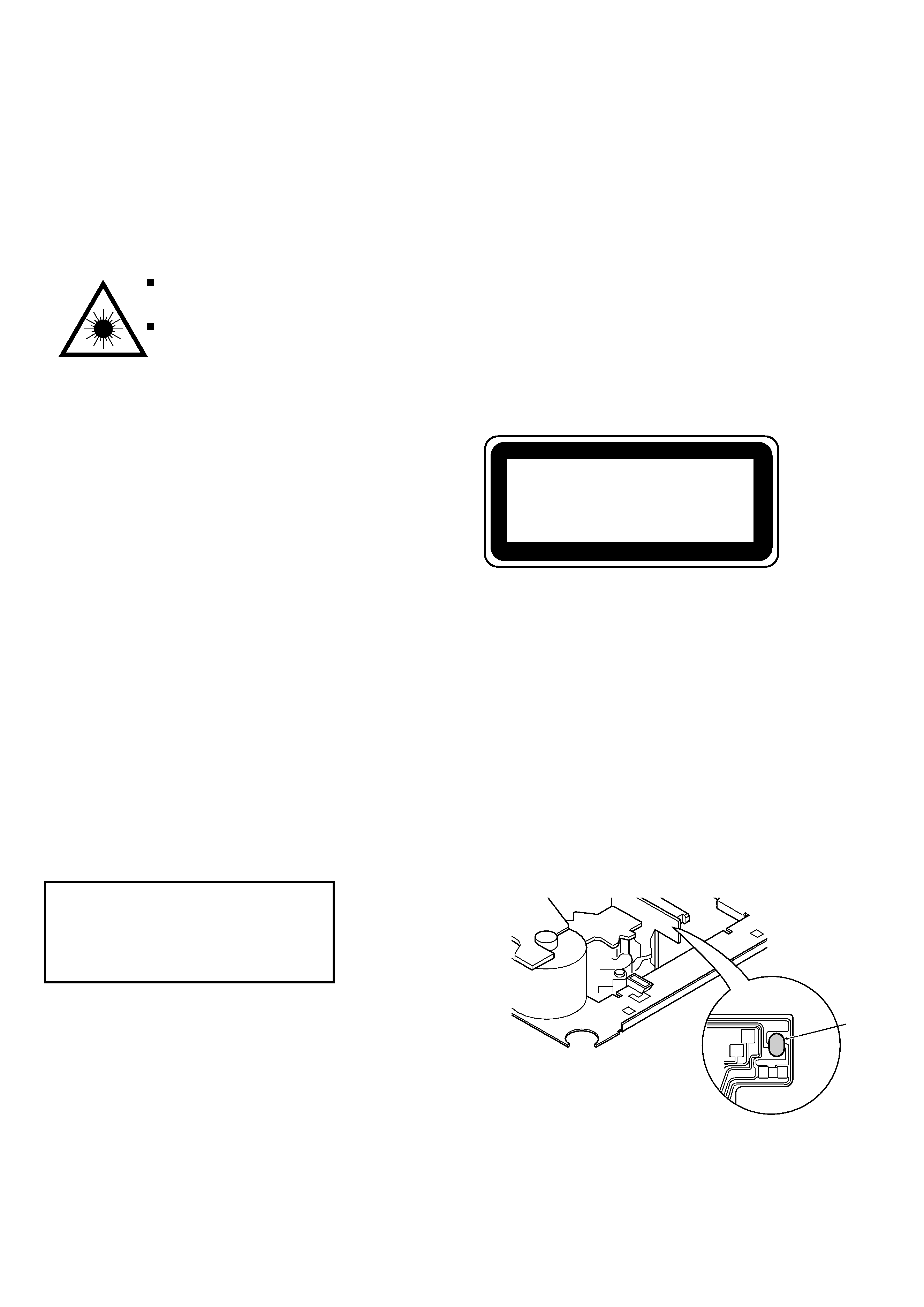
This Compact Disc player is classified as a CLASS 1
LASER product.
The CLASS 1 LASER PRODUCT label is located on the
rear exterior.
CLASS 1
LASER PRODUCT
KLASSE 1
LASER PRODUKT
LUOKAN 1
LASER LAITE
KLASS 1
LASER APPARAT
Precaution to replace Optical block
(KSM-213RSCM)
Body or clothes electrostatic potential could
ruin laser diode in the optical block. Be sure
ground body and workbench, and use care
the clothes do not touch the diode.
1) After the connection, remove solder shown in
right figure.
CD PICK-UP Assy PWB
Solder
Solder
-5-
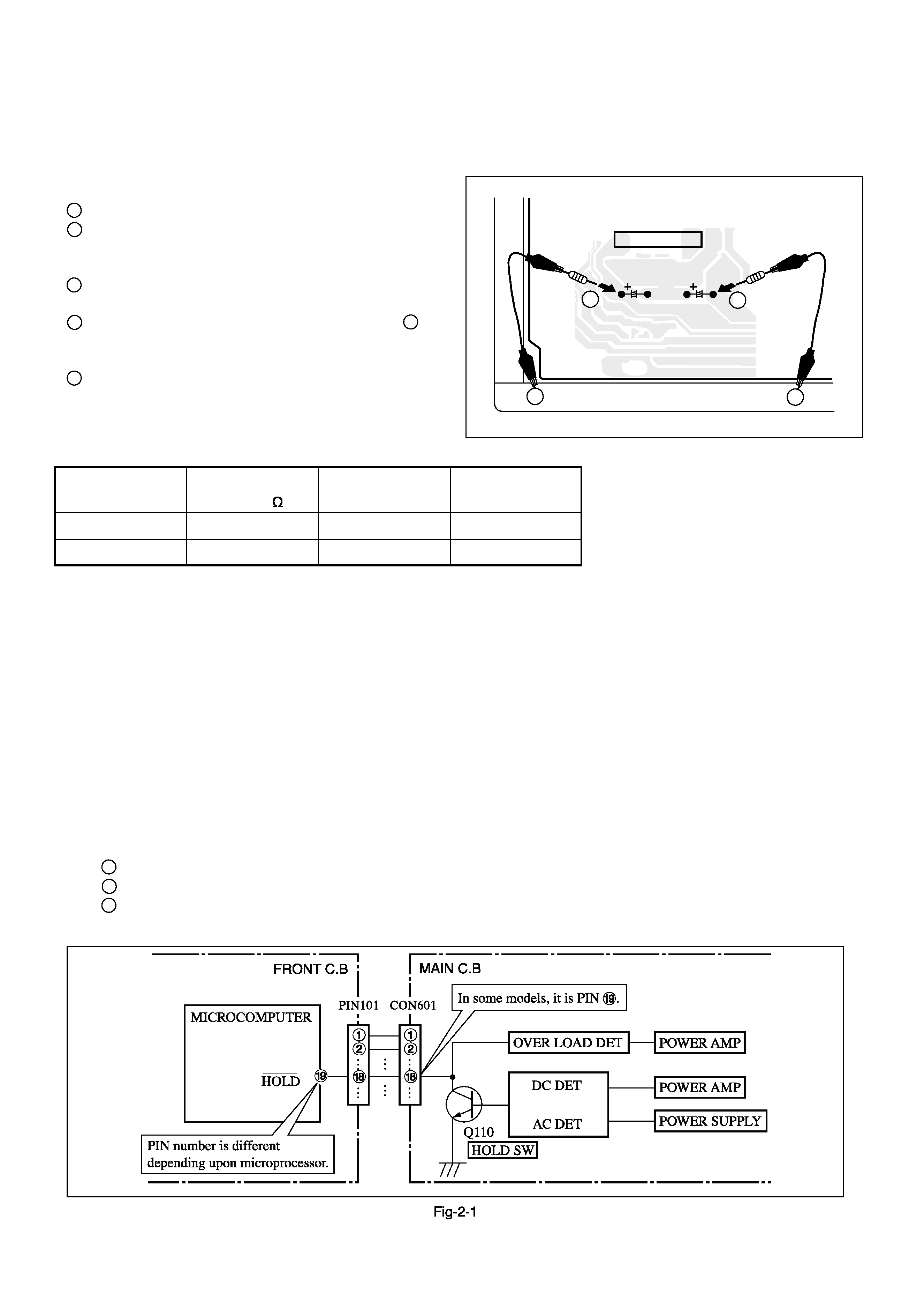
NOTE ON BEFORE STARTING REPAIR -1/2
1. Forced discharge of electrolytic capacitor of power supply block
When repair is going to be attempted in the set that uses relay circuit in the power supply block, electric potential is kept charged across the
electrolytic capacitors (C101, 102) even though AC power cord is removed. If repair is attempted in this condition, secondary defect can occur.
In order to prevent the secondary trouble, perform the following measures before starting repair work.
Discharge procedure
1 Remove the AC power cord.
2 Connect a discharging resistor at an end of lead wire that has
clips at both ends. Connect the other end of the lead wire to
metal chassis.
3 Contact the other end of the discharging resistor to the
positive (+) side (+VH) of C101. (For two seconds)
4 Contact the same end of the discharging resistor as step 3 to
the negative (-) side (-VH) of C102 in the same way.
(For two seconds)
5 Check that voltage across C101 and C102 has decreased to
1 V or less using a multimeter or an oscilloscope.
Select a discharging resistor referring to the following table.
Note: The reference numbers (C101, C102) of the electrolytic capacitors can change depending on the models. Be sure to check the reference numbers
of the charging capacitors on schematic diagram before starting the discharging work.
2. Check items before exchanging the MICROCOMPUTER
Be sure to check the following items before exchanging the MICROCOMPUTER. Exchange the MICROCOMPUTER after confirming that the
MICROCOMPUTER is surely defective.
2-1. Regarding the HOLD terminal of the MICROCOMPUTER
When the HOLD terminal (INPUT) of the MICROCOMPUTER is «H», the MICROCOMPUTER is judged to be operating correctly.
When this terminal is «L», the main power cannot be turned on. Therefore, be sure to check the terminal voltage of the HOLD terminal before
exchange.
When the MICROCOMPUTER is not defective, the HOLD terminal can also go «L» when the POWER AMPLIFIER has any abnormalities
that triggers the abnormality detection circuit on the MAIN C. B. that sets the HOLD terminal to «L».
· Good or no good judgement of the MICROCOMPUTER
1 Turn on the AC main power.
2 Confirm that the main power is turned on and the HOLD terminal of the MICROCOMPUTER keeps the «H» level or not.
3 When the HOLD terminal is «L» level, the abnormality detection circuit is judged to be working correctly and the MICRO
COMPUTER is judged to be good.
Fig-1
MAIN C.B
D101
C101
C102
3
4
2
2
Charging voltage (V)
Discharging
Rated power (W)
Parts number
(C101, 102)
resistor ( )
25-48
100
3
87-A00-247-090
49-140
220
5
87-A00-232-090