

Dell Vostro 3650
Руководство по эксплуатации
нормативная модель: D19M
нормативный тип: D19M002

Примечания, предупреждения и
предостережения
ПРИМЕЧАНИЕ: Указывает на важную информацию, которая поможет использовать компьютер более
эффективно.
ОСТОРОЖНО: ПРЕДУПРЕЖДЕНИЕ. Указывает на опасность повреждения оборудования или
потери данных и подсказывает, как этого избежать.
ПРЕДУПРЕЖДЕНИЕ: Указывает на риск повреждения оборудования, получения травм или на
угрозу для жизни.
© Dell Inc., 2015 г. Все права защищены. Данное изделие защищено американскими и международными законами об
авторских правах и интеллектуальной собственности. Dell™ и логотип Dell являются товарными знаками корпорации Dell в
Соединенных Штатах и (или) других странах. Все другие товарные знаки и наименования, упомянутые в данном документе,
могут являться товарными знаками соответствующих компаний.
2015 — 11
Ред. A00

Содержание
1 Работа с компьютером……………………………………………………………………………… 5
Подготовка к работе с внутренними компонентами компьютера……………………………………………………5
Выключение компьютера…………………………………………………………………………………………………………6
После работы с внутренними компонентами компьютера……………………………………………………………..7
2 Извлечение и установка компонентов………………………………………………………8
Рекомендуемые инструменты………………………………………………………………………………………………….. 8
Снятие крышки………………………………………………………………………………………………………………………8
Установка крышки………………………………………………………………………………………………………………….8
Снятие лицевой панели……………………………………………………………………………………………………………9
Установка лицевой панели……………………………………………………………………………………………………….9
Открытие дверцы лицевой панели…………………………………………………………………………………………….9
Извлечение жесткого диска в сборе…………………………………………………………………………………………10
Установка жесткого диска в сборе………………………………………………………………………………………….. 11
Извлечение оптического дисковода в сборе……………………………………………………………………………… 11
Установка оптического дисковода в сборе………………………………………………………………………………..12
Извлечение платы WLAN……………………………………………………………………………………………………….13
Установка платы WLAN…………………………………………………………………………………………………………13
Извлечение модуля памяти……………………………………………………………………………………………………. 14
Установка модуля памяти………………………………………………………………………………………………………14
Извлечение платы расширения PCIe………………………………………………………………………………………. 14
Установка плат расширения PCIe……………………………………………………………………………………………15
Извлечение модуля блока питания…………………………………………………………………………………………..15
Установка модуля блока питания…………………………………………………………………………………………….16
Извлечение переключателя питания……………………………………………………………………………………….. 16
Установка переключателя питания…………………………………………………………………………………………..17
Извлечение батареи типа «таблетка»………………………………………………………………………………………. 17
Установка батареи типа «таблетка»…………………………………………………………………………………………18
Извлечение радиатора в сборе……………………………………………………………………………………………….. 18
Установка радиатора в сборе…………………………………………………………………………………………………. 18
Извлечение процессора………………………………………………………………………………………………………….19
Установка процессора……………………………………………………………………………………………………………19
Извлечение системного вентилятора……………………………………………………………………………………….20
Установка системного вентилятора…………………………………………………………………………………………20
Извлечение системной платы………………………………………………………………………………………………… 20
Установка системной платы……………………………………………………………………………………………………21
Компоновка системной платы……………………………………………………………………………………………….. 22
3

3 Поиск и устранение неполадок………………………………………………………………. 23
Коды диагностических индикаторов питания……………………………………………………………………………23
Диагностические сообщения об ошибках…………………………………………………………………………………24
Системные сообщения об ошибке………………………………………………………………………………………….. 28
4 Параметры настройки системы…………………………………………………………….. 30
Краткое описание программы настройки системы……………………………………………………………………..33
Доступ к настройке системы…………………………………………………………………………………………………..33
5 Технические характеристики………………………………………………………………… 34
6 Обращение в компанию Dell…………………………………………………………………..38
4
1
Работа с компьютером
Подготовка к работе с внутренними компонентами
компьютера
Во избежание повреждения компьютера и для собственной безопасности следуйте приведенным ниже
указаниям по технике безопасности. Если не указано иное, каждая процедура, предусмотренная в данном
документе, подразумевает соблюдение следующих условий:
• прочитаны указания по технике безопасности, прилагаемые к компьютеру;
• для замены компонента или установки отдельно приобретенного компонента выполните процедуру снятия
в обратном порядке.
ПРЕДУПРЕЖДЕНИЕ: Отсоедените компьютер от всех источников питания перед снятием
крышки компьютера или панелей. После окончания работы с внутренними компонентами
компьютера, установите все крышки, панели и винты на место, перед тем как, подключить
компьютер к источнику питания.
ПРЕДУПРЕЖДЕНИЕ: Перед началом работы с внутренними компонентами компьютера
ознакомьтесь с указаниями по технике безопасности, прилагаемыми к компьютеру.
Дополнительные сведения о рекомендуемых правилах техники безопасности можно посмотреть на
начальной странице раздела, посвященного соответствию нормативным требованиям:
www.Dell.com/regulatory_compliance .
ОСТОРОЖНО: Многие виды ремонта могут быть выполнены только сертифицированным
техническим специалистом. Вам следует устранять неполадки и выполнять простой ремонт,
разрешенный в соответствии с документацией к изделию или проводимый в соответствии с
указаниями, которые можно найти в Интернете, получить по телефону или в службе технической
поддержки. На повреждения, причиной которых стало обслуживание без разрешения компании
Dell, гарантия не распространяется. Прочтите инструкции по технике безопасности, прилагаемые к
изделию, и следуйте им.
ОСТОРОЖНО: Во избежание электростатического разряда следует заземлиться, надев
антистатический браслет или периодически прикасаясь к некрашеной металлической поверхности
(например, к разъемам на задней панели компьютера).
ОСТОРОЖНО: Соблюдайте осторожность при обращении с компонентами и платами. Не следует
дотрагиваться до компонентов и контактов платы. Держите плату за края или за металлическую
монтажную скобу. Такие компоненты, как процессор, следует держать за края, а не за контакты.
ОСТОРОЖНО: При отсоединении кабеля беритесь за разъем или специальную петлю на нем. Не
тяните за кабель. На некоторых кабелях имеются разъемы с фиксирующими защелками. Перед
отсоединением кабеля такого типа необходимо нажать на фиксирующие защелки. При
разъединении разъемов старайтесь разносить их по прямой линии, чтобы не погнуть контакты. А
перед подсоединением кабеля убедитесь в правильной ориентации и соосности частей разъемов.
ПРИМЕЧАНИЕ: Цвет компьютера и некоторых компонентов может отличаться от цвета, указанного в
этом документе.
5
Во избежание повреждения компьютера выполните следующие шаги, прежде чем приступать к работе с
внутренними компонентами компьютера.
1. Чтобы не поцарапать крышку компьютера, работы следует выполнять на плоской и чистой поверхности.
2. Выключите компьютер (см. раздел Выключение компьютера).
ОСТОРОЖНО: При отсоединении сетевого кабеля необходимо сначала отсоединить его от
компьютера, а затем от сетевого устройства.
3. Отсоедините от компьютера все сетевые кабели.
4. Отсоедините компьютер и все внешние устройства от электросети.
5. Нажмите и не отпускайте кнопку питания, пока компьютер не подключен к электросети, чтобы заземлить
системную плату.
6. Снимите крышку.
ОСТОРОЖНО: Прежде чем прикасаться к чему-либо внутри компьютера, снимите
статическое электричество, прикоснувшись к некрашеной металлической поверхности
(например, на задней панели компьютера). Во время работы периодически прикасайтесь к
некрашеной металлической поверхности, чтобы снять статическое электричество, которое
может повредить внутренние компоненты.
Выключение компьютера
ОСТОРОЖНО: Во избежание потери данных сохраните и закройте все открытые файлы и выйдите
из всех открытых программ перед выключением компьютера.
1. Выключение компьютера (Windows 8.1):
• При использовании сенсорного устройства:
a. Проведите пальцем с правого края экрана, открыв меню панели Charms, и выберите пункт
Параметры.
b. Select (Выбрать) а затем выберите Завершение работы.
или
a. На Главном экране коснитесь а затем выберите Завершение работы.
• При использовании мыши:
a. Укажите мышью правый верхний угол экрана и щелкните Параметры.
b. Нажмите а затем выберите Завершение работы.
или
a. На Главном экране щелкните а затем выберите Завершение работы.
2. Выключение компьютера (Windows 7):
Нажмите Пуск .
a.
b. Щелкните Завершение работы.
или
a. Нажмите Пуск .
b. Нажмите стрелку в нижнем правом углу менюПуск, а затем нажмите Выход из системы.
6

3. Убедитесь, что компьютер и все подключенные к нему устройства выключены. Если компьютер и
подключенные устройства не выключились автоматически по завершении работы операционной системы,
нажмите и не отпускайте кнопку питания примерно 6 секунд, пока они не выключатся.
После работы с внутренними компонентами компьютера
После завершения любой процедуры замены не забудьте подключить все внешние устройства, платы и кабели,
прежде чем включать компьютер.
1. Установите на место крышку.
ОСТОРОЖНО: Чтобы подсоединить сетевой кабель, сначала подсоедините его к сетевому
устройству, а затем к компьютеру.
2. Подсоедините к компьютеру все телефонные или сетевые кабели.
3. Подключите компьютер и все внешние устройства к электросети.
4. Включите компьютер.
5. Если необходимо, проверьте исправность работы компьютера, запустив программу Dell Diagnostics.
7
2
Извлечение и установка компонентов
В этом разделе приведены подробные сведения по извлечению и установке компонентов данного компьютера.
Рекомендуемые инструменты
Для выполнения процедур, описанных в этом документе, требуются следующие инструменты:
• маленькая шлицевая отвертка;
• крестовая отвертка;
• небольшая пластиковая палочка.
Снятие крышки
1. Выполните процедуры, приведенные в разделе Подготовка к работе с внутренними компонентами
компьютера.
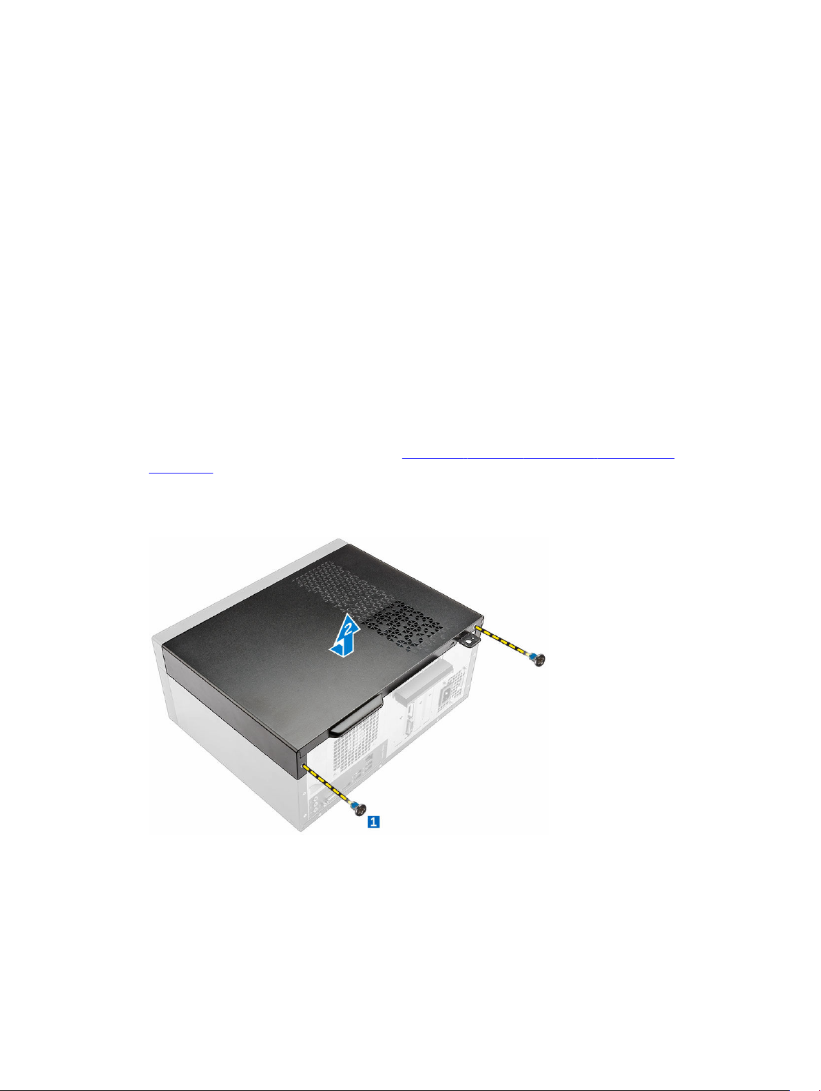
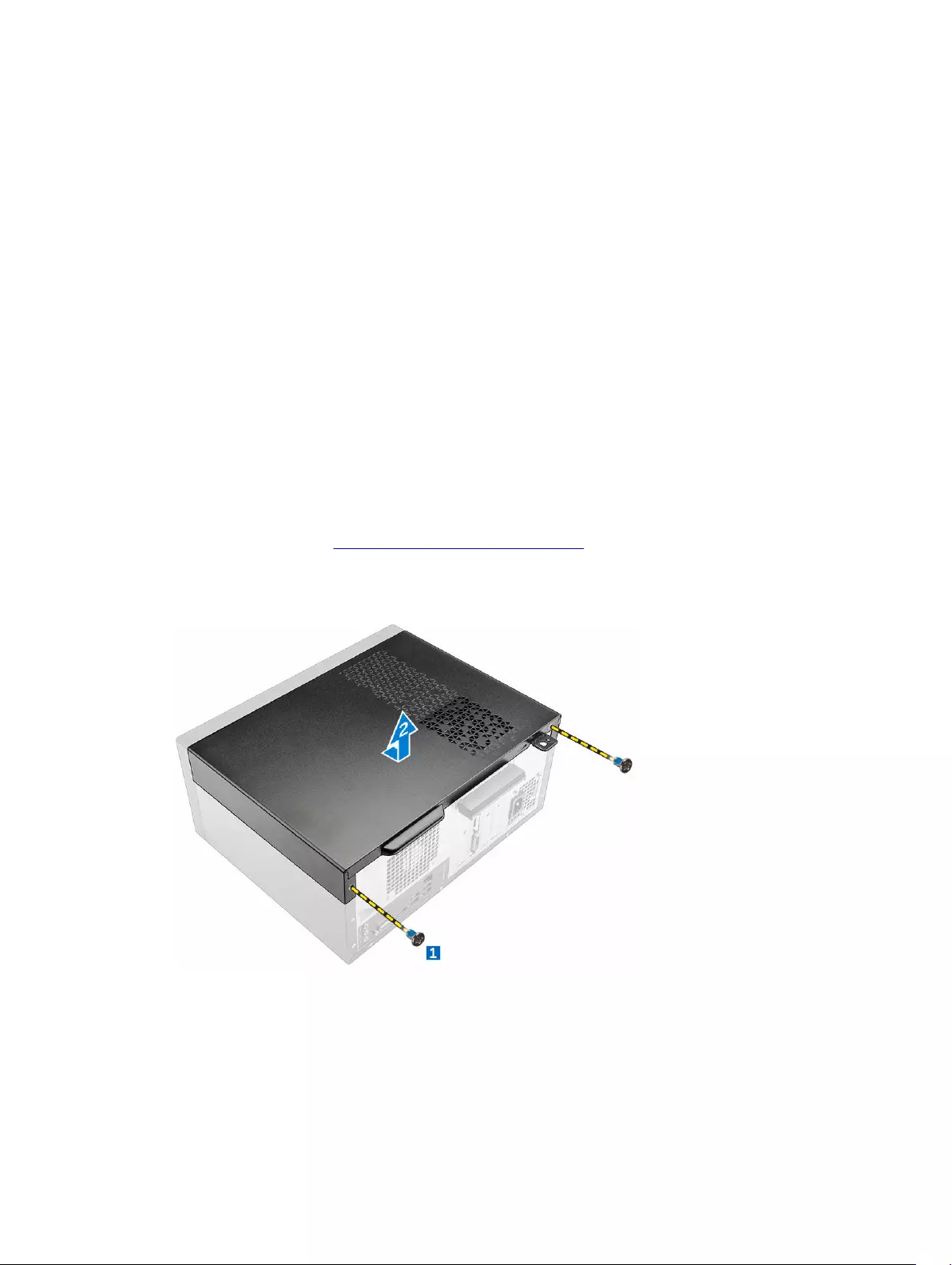
2. Снятие крышки:
a. Выкрутите винты, с помощью которых крышка крепится к компьютеру [1].
b. Сдвиньте крышку вперед и поднимите ее, чтобы извлечь из корпуса компьютера [2].
Установка крышки
1. Установите крышку на компьютер и сдвиньте ее, чтобы она встала на место со щелчком.
2. Затяните винты, чтобы прикрепить крышку к компьютеру.
8
3. Выполните процедуру, приведенную в разделе После работы с внутренними компонентами компьютера.
Снятие лицевой панели
1. Выполните процедуры, приведенные в разделе Подготовка к работе с внутренними компонентами
компьютера.
2. Снимите крышку.
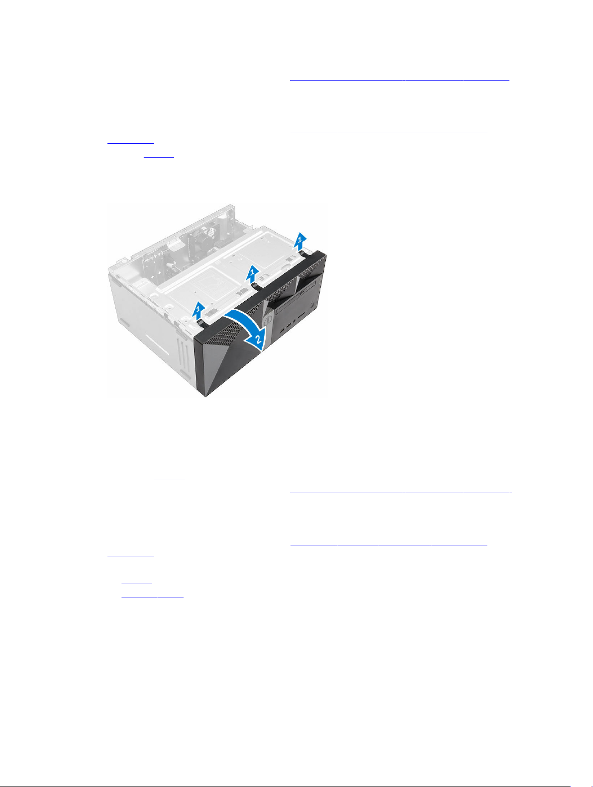
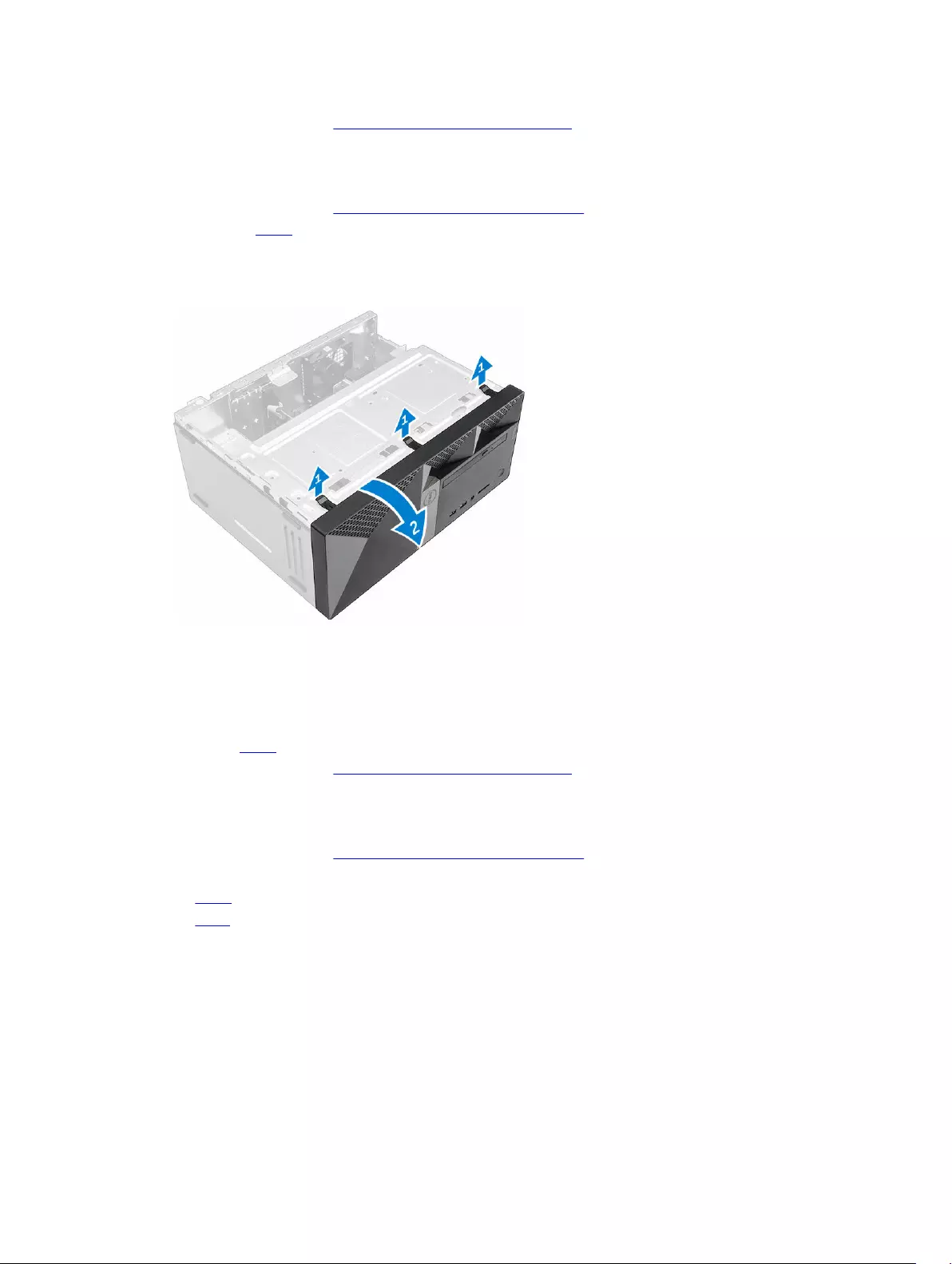
3. Снятие лицевой панели:
a. Приподнимите защелки, чтобы высвободить лицевую панель из корпуса компьютера.
b. Снимите лицевую панель с компьютера.
Установка лицевой панели
1. Вставьте фиксаторы лицевой панели в пазы на корпусе компьютера.
2. Нажмите на лицевую панель до щелчка фиксаторов.
3. Установите крышку.
4. Выполните процедуру, приведенную в разделе После работы с внутренними компонентами компьютера.
Открытие дверцы лицевой панели
1. Выполните процедуры, приведенные в разделе Подготовка к работе с внутренними компонентами
компьютера.
2. Снимите:
• крышку
• лицевую панель
3. Потяните дверцу лицевой панели, чтобы открыть ее.
9
ОСТОРОЖНО: Дверца передней панели открывается только в определенных пределах.
Максимально допустимый уровень указан в печатной метке.
Извлечение жесткого диска в сборе
1. Выполните процедуры, приведенные в разделе Подготовка к работе с внутренними компонентами
компьютера.
2. Снимите:
• крышку
• лицевую панель
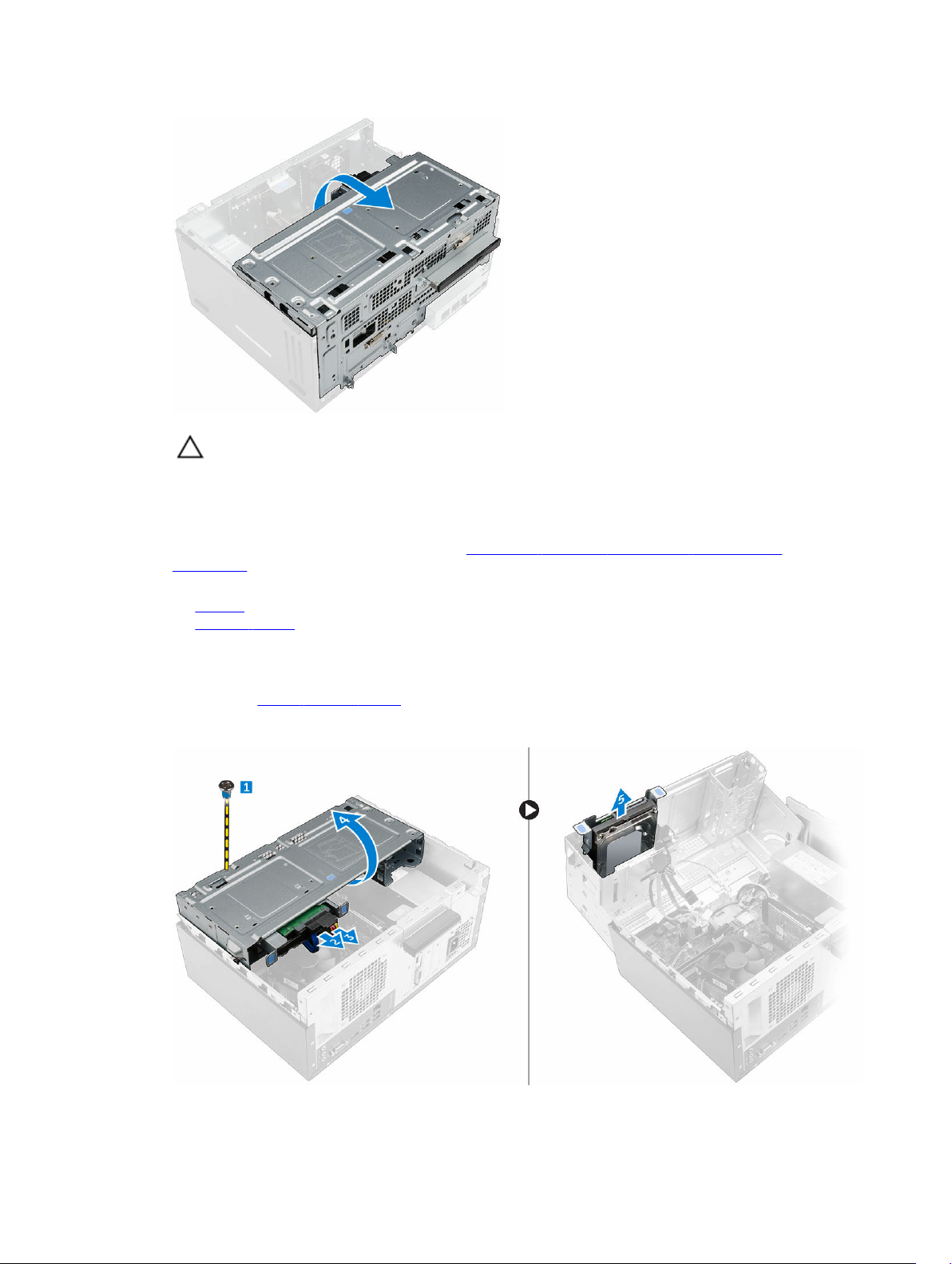
3. Извлечение жесткого диска в сборе:
a. Открутите винт, которым жесткий диск в сборе крепится к дверце лицевой панели [1].
b. Отсоедините кабели жесткого диска в сборе от разъемов на жестком диске [2, 3].
c. Откройте дверцу лицевой панели [4].
d. Удерживайте на металлические выступы с обеих сторон , потяните жесткий диск в сборе и извлеките
его из корпуса компьютера[6].
10
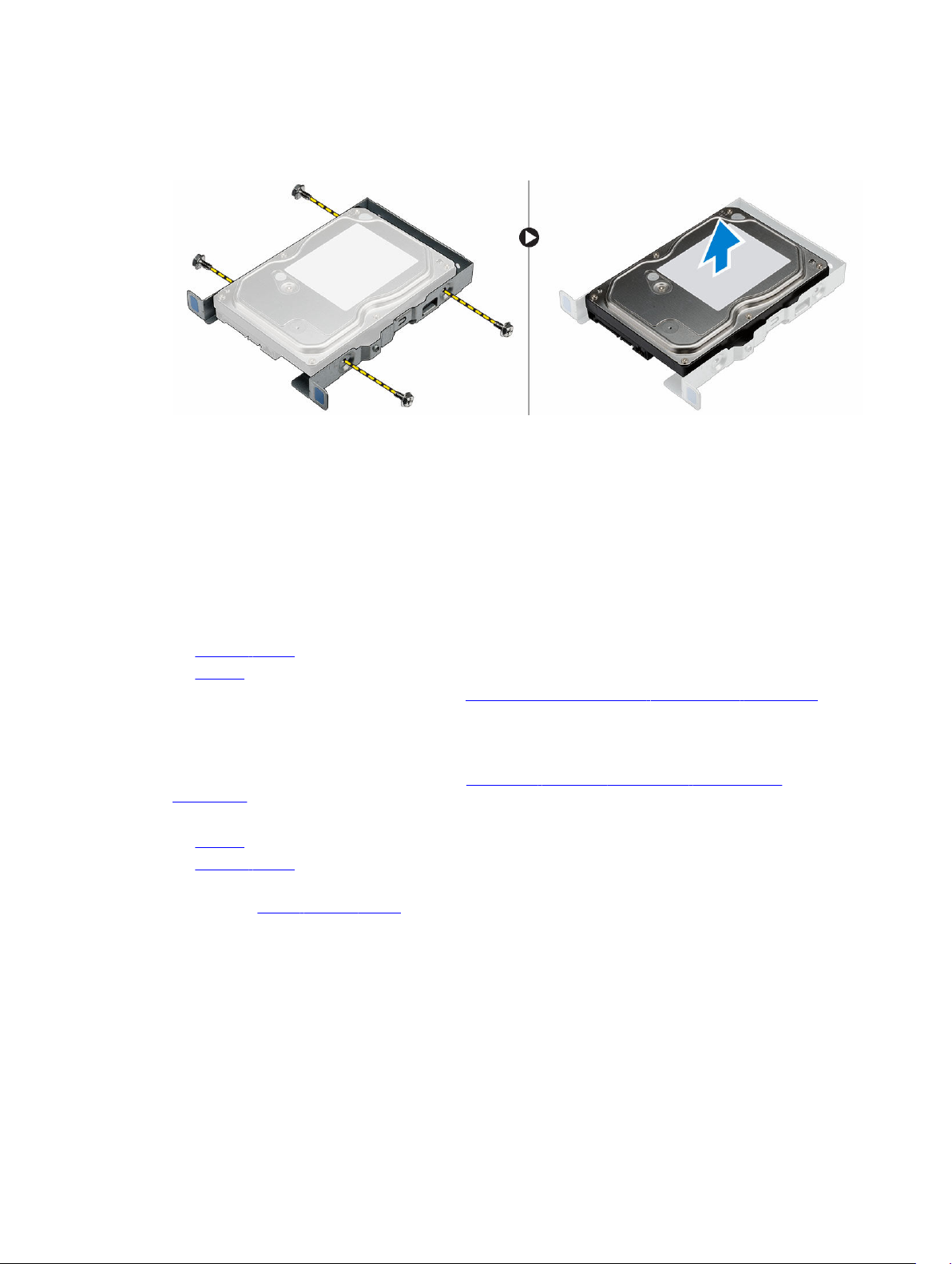
4. Извлечение жесткого диска из каркаса жесткого диска:
a. Выверните винты, которыми каркас жесткого диска крепится к жесткому диску.
b. Извлеките жесткий диск из каркаса жесткого диска.
Установка жесткого диска в сборе
1. Вставьте жесткий диск в каркас жесткого диска.
2. Затяните винты, которыми крепится кронштейн жесткого диска.
3. Вставьте жесткий диск в сборе в разъем на компьютере.
4. Закройте дверцу лицевой панели.
5. Установите винт, которым жесткий диск в сборе крепится к дверце лицевой панели.
6. Подключите кабель SATA и кабель питания к разъемам на жестком диске.
7. Установите:
• лицевую панель
• крышку
8. Выполните процедуру, приведенную в разделе После работы с внутренними компонентами компьютера.
Извлечение оптического дисковода в сборе
1. Выполните процедуры, приведенные в разделе Подготовка к работе с внутренними компонентами
компьютера.
2. Снимите:
• крышку
• лицевую панель
3. Извлечение оптического дисковода в сборе:
a. Откройте дверцу лицевой панели.
b. Отсоедините кабель передачи данных и кабель питания от разъемов оптического дисковода в сборе [1,
2].
c. Закройте дверцу лицевой панели [3].
d. Отвинтите винт, которым оптический дисковод в сборе крепится к компьютеру [4].
e. Сдвиньте оптический дисковод в сборе и извлеките его из компьютера [5].
11
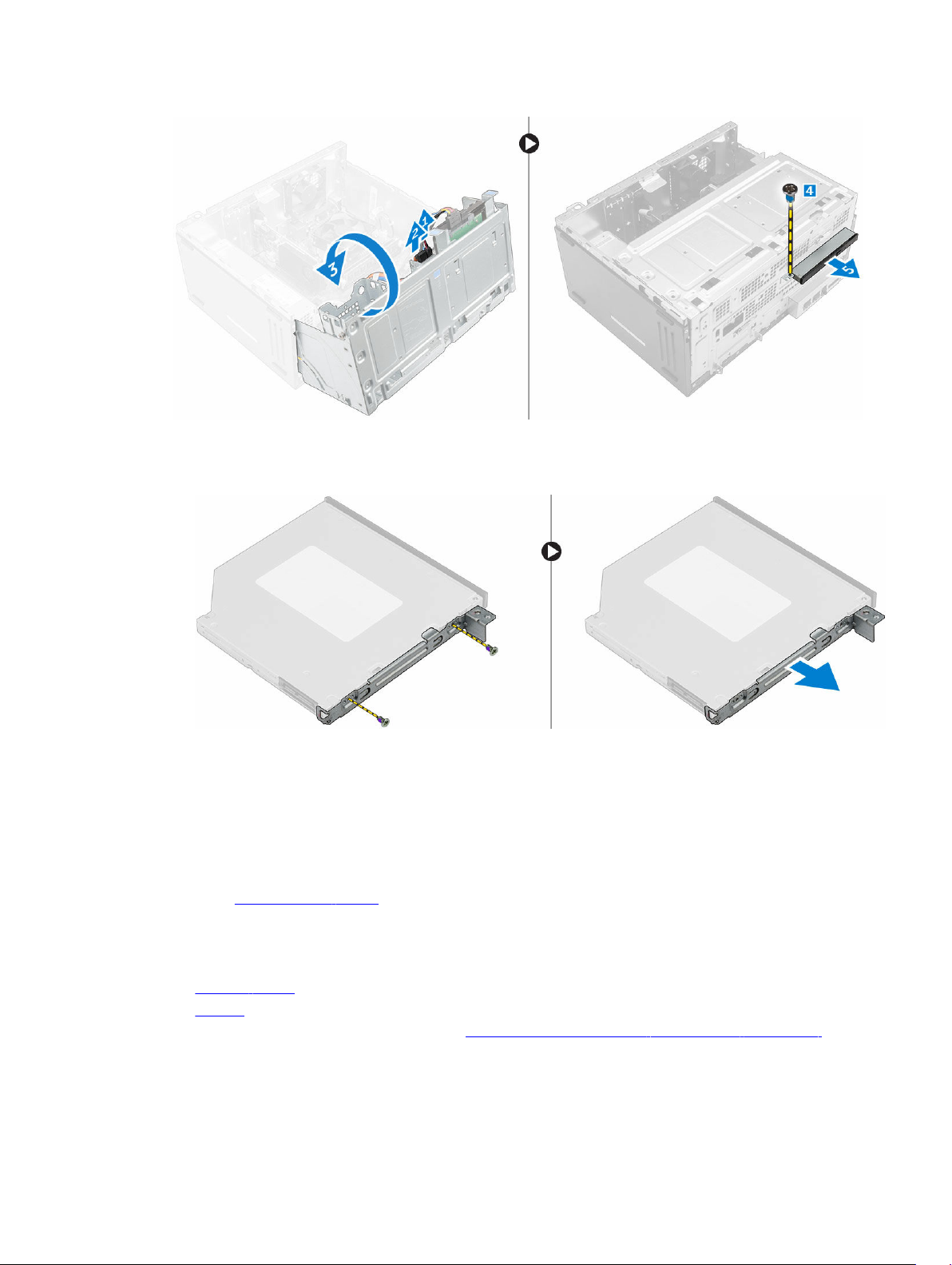
4. Извлечение кронштейна оптического дисковода:
a. Отвинтите винты, которыми кронштейн оптического дисковода крепится к оптическому дисководу.
b. Снимите кронштейн оптического дисковода с оптического дисковода.
Установка оптического дисковода в сборе
1. Установите кронштейн оптического дисковода на оптический дисковод.
2. Затяните винты, которыми кронштейн оптического дисковода крепится к оптическому дисководу.
3. Вставьте оптический дисковод в сборе в отсек оптического дисковода на место до щелчка.
4. Затяните винт, чтобы прикрепить оптический дисковод в сборе к компьютеру.
5. Откройте дверцу лицевой панели.
6. Подключите кабель передачи данных и кабель питания к разъемам на оптическом дисководе в сборе.
7. Закройте дверцу лицевой панели.
8. Установите:
• лицевую панель
• крышку
9. Выполните процедуру, приведенную в разделе После работы с внутренними компонентами компьютера.
12
Loading…
Manual
View the manual for the Dell Vostro 3650 here, for free. This user manual comes under the category desktops and has been rated by 1 people with an average of a 8.5. This manual is available in the following languages: English. Do you have a question about the Dell Vostro 3650?
Ask your question here
Dell Vostro 3650 specifications
Below you will find the product specifications and the manual specifications of the Dell Vostro 3650.
Processor frequency
2.7 GHz
Total storage capacity
500 GB
Optical drives quantity
1
General
| Brand | Dell |
| Model | Vostro 3650 | 3W0CH+210-AFOQ |
| Product | desktop |
| EAN | 5397063823383, 5397063823390, 5397063823406, 5397063896554, 5397063896561, 5397063896578, 5397063896585, 5397063897278, 5397063897285, 5397063897292, 5397063924264, 5397063936427, 5397063936434, 5397063936441, 5397063941865, 5397063975884, 5397063975891, 5397063976058, 5397063976065, 5397063976072 |
| Language | English |
| Filetype | Manual (PDF) |
Processor
| Processor frequency | 2.7 GHz |
| Processor family | Intel® Core™ i5 |
| Processor model | i5-6400 |
| Processor cores | 4 |
| Processor boost frequency | 3.3 GHz |
| Processor socket | LGA 1151 (Socket H4) |
| Processor cache | 6 MB |
| Processor cache type | Smart Cache |
| System bus rate | 8 GT/s |
| Processor threads | 4 |
| Number of processors installed | 1 |
| Processor lithography | 14 nm |
| Stepping | R0 |
| PCI Express slots version | 3.0 |
| Processor operating modes | 64-bit |
| Tcase | 71 °C |
| Bus type | DMI3 |
| PCI Express configurations | 1×16, 2×8, 1×8+2×4 |
| Thermal Design Power (TDP) | 65 W |
| Processor codename | Skylake |
| Maximum number of PCI Express lanes | 16 |
| Processor series | Intel Core i5-6400 Desktop series |
| Maximum internal memory supported by processor | 64 GB |
| Memory types supported by processor | DDR3L-SDRAM, DDR4-SDRAM |
| Memory clock speeds supported by processor | 2133,1333,1600,1866 MHz |
| Memory bandwidth supported by processor (max) | 34.1 GB/s |
| ECC supported by processor | No |
| Memory voltage supported by processor | 1.35 V |
| Processor front side bus | — MHz |
| Processor manufacturer | Intel |
| Processor generation | 6th gen Intel® Core™ i5 |
Design
| Product colour | Black |
| Placement supported | Vertical |
| Number of 3.5″ bays | 1 |
| Number of 5.25″ bays | 1 |
| Number of 2.5″ bays | 1 |
| Chassis type | Mini Tower |
Performance
| Product type | PC |
| Motherboard chipset | Intel® H110 |
| Compatible processor series | Intel Celeron, Intel Pentium |
| Audio output channels | 5.1 channels |
| Password protection | Yes |
Memory
| Internal memory | 4 GB |
| Internal memory type | DDR3L-SDRAM |
| Maximum internal memory | 16 GB |
| Memory layout (slots x size) | 1 x 4 GB |
| Memory slots | 2x DIMM |
| Memory clock speed | 1600 MHz |
| Non-ECC | Yes |
| Memory channels | Dual-channel |
Storage
| Total storage capacity | 500 GB |
| Card reader integrated | — |
| Storage media | HDD |
| Number of storage drives installed | 1 |
| Number of HDDs installed | 1 |
| HDD capacity | 500 GB |
| Optical drive type | DVD±RW |
Other features
| Optical drives quantity | 1 |
| Intel segment tagging | Home Office, Small Business |
Graphics
| Discrete graphics card | No |
| On-board graphics card | Yes |
| Discrete graphics card model | Not available |
| On-board graphics card family | Intel® HD Graphics |
| On-board graphics card model | Intel® HD Graphics 530 |
| On-board graphics card base frequency | 350 MHz |
| On-board graphics card dynamic frequency (max) | 950 MHz |
| On-board graphics card ID | 1912 |
| Maximum on-board graphics card memory | 64 GB |
| Number of displays supported (on-board graphics) | 3 |
| On-board graphics card OpenGL version | 4.4 |
| On-board graphics card DirectX version | 12.0 |
Software
| Operating system installed | Windows 10 Pro |
| Operating system architecture | 64-bit |
| Drivers included | Yes |
Network
| Ethernet LAN | Yes |
| Ethernet LAN data rates | 10,100,1000 Mbit/s |
| Cabling technology | 10/100/1000Base-T(X) |
| Wi-Fi | Yes |
| Bluetooth | Yes |
| Wi-Fi standards | 802.11b, 802.11g, Wi-Fi 4 (802.11n) |
| Bluetooth version | 4.0 |
| Top Wi-Fi standard | Wi-Fi 4 (802.11n) |
Power
| Power supply | 255 W |
| Power supply input frequency | 50 — 60 Hz |
| Power supply input voltage | 100 — 240 V |
Weight & dimensions
| Width | 436.3 mm |
| Depth | 175 mm |
| Height | 380 mm |
| Weight | 8500 g |
Ports & interfaces
| USB 2.0 ports quantity | 4 |
| USB 3.2 Gen 1 (3.1 Gen 1) Type-A ports quantity | 2 |
| USB 3.2 Gen 1 (3.1 Gen 1) Type-C ports quantity | 0 |
| USB 3.2 Gen 2 (3.1 Gen 2) Type-A ports quantity | 0 |
| USB 3.2 Gen 2 (3.1 Gen 2) Type-C ports quantity | 0 |
| Thunderbolt 3 ports quantity | 0 |
| VGA (D-Sub) ports quantity | 1 |
| DVI port | No |
| HDMI ports quantity | 1 |
| Ethernet LAN (RJ-45) ports | 1 |
| Line-in | Yes |
| Line-out | Yes |
| Microphone in | Yes |
| Headphone outputs | 1 |
| Combo headphone/mic port | Yes |
Operational conditions
| Operating temperature (T-T) | 10 — 35 °C |
| Operating relative humidity (H-H) | -40 — 65 % |
| Operating altitude | -15.2 — 3048 m |
| Non-operating altitude | -15.2 — 10668 m |
| Storage temperature (T-T) | -40 — 65 °C |
Sustainability
| Sustainability certificates | ENERGY STAR |
Display
| Display included | Yes |
| Display diagonal | 19.5 « |
| Display type | LED |
| Display resolution | 1440 x 900 pixels |
| Panel type | IPS |
| Native aspect ratio | 16:10 |
| Contrast ratio (typical) | 1000:1 |
| Display number of colours | 16.78 million colours |
| Display brightness | 250 cd/m² |
| Viewing angle, horizontal | 178 ° |
| Viewing angle, vertical | 178 ° |
Expansion slots
| PCI Express x1 slots | 2 |
| PCI Express x16 slots | 1 |
Packaging content
| Cables included | AC |
| Manual | Yes |
| AC adapter included | Yes |
Processor special features
| Supported instruction sets | SSE4.2, AVX 2.0, SSE4.1 |
| Processor code | SR2BY |
| Intel® Hyper Threading Technology (Intel® HT Technology) | No |
| Intel® Turbo Boost Technology | 2.0 |
| Intel® Quick Sync Video Technology | Yes |
| Intel® InTru™ 3D Technology | Yes |
| Intel® Wireless Display (Intel® WiDi) | Yes |
| Intel® Clear Video HD Technology (Intel® CVT HD) | Yes |
| Intel® Insider™ | Yes |
| Intel® Smart Cache | Yes |
| Intel® AES New Instructions (Intel® AES-NI) | Yes |
| Enhanced Intel SpeedStep Technology | Yes |
| Execute Disable Bit | Yes |
| Idle States | Yes |
| Thermal Monitoring Technologies | Yes |
| Intel Trusted Execution Technology | No |
| Scalability | 1S |
| CPU configuration (max) | 1 |
| Intel Enhanced Halt State | Yes |
| Intel® Clear Video Technology for Mobile Internet Devices (Intel CVT for MID) | Yes |
| Intel VT-x with Extended Page Tables (EPT) | Yes |
| Embedded options available | No |
| Graphics & IMC lithography | 14 nm |
| Thermal solution specification | PCG 2015C |
| Intel 64 | Yes |
| Intel Stable Image Platform Program (SIPP) | No |
| Intel® OS Guard | Yes |
| Intel Virtualization Technology for Directed I/O (VT-d) | Yes |
| Intel Clear Video Technology | Yes |
| Intel Secure Key Technology version | 1.00 |
| Intel Small Business Advantage (SBA) version | 1.00 |
| Intel Virtualization Technology (VT-x) | Yes |
| Intel Stable Image Platform Program (SIPP) version | 0.00 |
| Intel TSX-NI version | 0.00 |
| Processor package size | 37.5 x 37.5 mm |
| Conflict-Free processor | Yes |
| Processor ARK ID | 88185 |
| Intel® Identity Protection Technology (Intel® IPT) | Yes |
| Intel TSX-NI | No |
| Intel® Secure Key | Yes |
| Intel Identity Protection Technology version | 1.00 |
| Intel Software Guard Extensions (Intel SGX) | Yes |
show more
Frequently asked questions
Can’t find the answer to your question in the manual? You may find the answer to your question in the FAQs about the Dell Vostro 3650 below.
What is the weight of the Dell Vostro 3650?
The Dell Vostro 3650 has a weight of 8500 g.
What is the height of the Dell Vostro 3650?
The Dell Vostro 3650 has a height of 380 mm.
What is the width of the Dell Vostro 3650?
The Dell Vostro 3650 has a width of 436.3 mm.
What is the depth of the Dell Vostro 3650?
The Dell Vostro 3650 has a depth of 175 mm.
What is HDMI?
HDMI stands for High-Definition Multimedia Interface. An HDMI cable is used to transport audio and video signals between devices.
What is the screen size of the Dell Vostro 3650?
The screen size of the Dell Vostro 3650 is 19.5 «.
What is the screen resolution of the display of the Dell Vostro 3650?
The screen resolution of the Dell Vostro 3650 is 1440 x 900 pixels.
What does the download speed on the internet depend on?
The download speed on the internet depends on the type of connection you have. If you have a 25 Mb/s connection this means that theoretically you should be able to download 25 MB per second.
How do I clean my keyboard?
Hold the keyboard upside down and use a can of compressed air to blow away the dirt. The keys can even be cleaned with a damp cloth.
Is the manual of the Dell Vostro 3650 available in English?
Yes, the manual of the Dell Vostro 3650 is available in English .
Is your question not listed? Ask your question here

Dell Vostro 3650
Owner’s Manual
Regulatory Model: D19M
Regulatory Type: D19M002

Notes, cautions, and warnings
NOTE: A NOTE indicates important information that helps you make better use of your computer.
CAUTION: A CAUTION indicates either potential damage to hardware or loss of data and tells you
how to avoid the problem.
WARNING: A WARNING indicates a potential for property damage, personal injury, or death.
Copyright © 2015 Dell Inc. All rights reserved. This product is protected by U.S. and international copyright and
intellectual property laws. Dell™ and the Dell logo are trademarks of Dell Inc. in the United States and/or other
jurisdictions. All other marks and names mentioned herein may be trademarks of their respective companies.
2015 — 11
Rev. A00

Contents
1 Working on your computer………………………………………………………………………5
Before working inside your computer……………………………………………………………………………………..5
Turning Off Your Computer……………………………………………………………………………………………………6
After working inside your computer………………………………………………………………………………………..6
2 Removing and installing components……………………………………………………..8
Recommended tools……………………………………………………………………………………………………………..8
Removing the cover………………………………………………………………………………………………………………8
Installing the cover………………………………………………………………………………………………………………..8
Removing the bezel……………………………………………………………………………………………………………… 9
Installing the bezel……………………………………………………………………………………………………………….. 9
Opening the front bezel door…………………………………………………………………………………………………9
Removing the hard drive assembly………………………………………………………………………………………..10
Installing the hard drive assembly…………………………………………………………………………………………. 11
Removing the optical drive assembly …………………………………………………………………………………… 11
Installing the optical drive assembly ……………………………………………………………………………………..12
Removing the WLAN card……………………………………………………………………………………………………. 13
Installing the WLAN Card…………………………………………………………………………………………………….. 13
Removing the memory module…………………………………………………………………………………………….14
Installing the memory module………………………………………………………………………………………………14
Removing the PCIe expansion card……………………………………………………………………………………… 14
Installing the PCIe expansion card…………………………………………………………………………………………15
Removing the power supply unit (PSU)………………………………………………………………………………….15
Installing the power supply unit (PSU)……………………………………………………………………………………16
Removing the power switch………………………………………………………………………………………………… 16
Installing the power switch………………………………………………………………………………………………….. 17
Removing the coin cell battery…………………………………………………………………………………………….. 17
Installing the coin cell battery……………………………………………………………………………………………….18
Removing the heat sink assembly………………………………………………………………………………………… 18
Installing the heat sink assembly………………………………………………………………………………………….. 18
Removing the processor………………………………………………………………………………………………………19
Installing the processor………………………………………………………………………………………………………..19
Removing the system fan……………………………………………………………………………………………………. 20
Installing the system fan……………………………………………………………………………………………………… 20
Removing the system board…………………………………………………………………………………………………20
Installing the system board………………………………………………………………………………………………….. 21
System Board Layout………………………………………………………………………………………………………….. 22
3

3 Troubleshooting your computer……………………………………………………………23
Diagnostic power LED codes………………………………………………………………………………………………. 23
Diagnostic error messages………………………………………………………………………………………………….. 24
System error messages………………………………………………………………………………………………………..28
4 System Setup Options…………………………………………………………………………… 29
System Setup overview……………………………………………………………………………………………………….. 31
Accessing System Setup……………………………………………………………………………………………………… 32
5 Specifications………………………………………………………………………………………… 33
6 Contacting Dell……………………………………………………………………………………… 37
4

1
Working on your computer
Before working inside your computer
Use the following safety guidelines to help protect your computer from potential damage and to help to
ensure your personal safety. Unless otherwise noted, each procedure included in this document assumes
that the following conditions exist:
• You have read the safety information that shipped with your computer.
• A component can be replaced or—if purchased separately—installed by performing the removal
procedure in reverse order.
WARNING: Disconnect all power sources before opening the computer cover or panels. After you
finish working inside the computer, replace all covers, panels, and screws before connecting to
the power source.
WARNING: Before working inside your computer, read the safety information that shipped with
your computer. For additional safety best practices information, see the Regulatory Compliance
Homepage at www.Dell.com/regulatory_compliance
CAUTION: Many repairs may only be done by a certified service technician. You should only
perform troubleshooting and simple repairs as authorized in your product documentation, or as
directed by the online or telephone service and support team. Damage due to servicing that is
not authorized by Dell is not covered by your warranty. Read and follow the safety instructions
that came with the product.
CAUTION: To avoid electrostatic discharge, ground yourself by using a wrist grounding strap or
by periodically touching an unpainted metal surface, such as a connector on the back of the
computer.
CAUTION: Handle components and cards with care. Do not touch the components or contacts
on a card. Hold a card by its edges or by its metal mounting bracket. Hold a component such as a
processor by its edges, not by its pins.
CAUTION: When you disconnect a cable, pull on its connector or on its pull-tab, not on the cable
itself. Some cables have connectors with locking tabs; if you are disconnecting this type of cable,
press in on the locking tabs before you disconnect the cable. As you pull connectors apart, keep
them evenly aligned to avoid bending any connector pins. Also, before you connect a cable,
ensure that both connectors are correctly oriented and aligned.
NOTE: The color of your computer and certain components may appear differently than shown in
this document.
To avoid damaging your computer, perform the following steps before you begin working inside the
computer.
1. Ensure that your work surface is flat and clean to prevent the computer cover from being scratched.
2. Turn off your computer (see Turning off your computer).
CAUTION: To disconnect a network cable, first unplug the cable from your computer and
then unplug the cable from the network device.
5
3. Disconnect all network cables from the computer.
4. Disconnect your computer and all attached devices from their electrical outlets.
5. Press and hold the power button while the computer is unplugged to ground the system board.
6. Remove the cover.
CAUTION: Before touching anything inside your computer, ground yourself by touching an
unpainted metal surface, such as the metal at the back of the computer. While you work,
periodically touch an unpainted metal surface to dissipate static electricity, which could
harm internal components.
Turning Off Your Computer
CAUTION: To avoid losing data, save and close all open files and exit all open programs before
you turn off your computer.
1. Turning off your computer (Windows 8.1):
• Using a touch enabled device:
a. Swipe in from the right edge of the screen, opening the Charms menu and select Settings.
b. Select and then select Shut down.
or
a. On the Home screen, touch and then select Shut down.
• Using a mouse:
a. Point to upper-right corner of the screen and click Settings.
b. Click and then select Shut down.
or
a. On the Home screen, click and then select Shut down.
2. Turning off your computer (Windows 7):
a. Click Start .
b. Click Shut Down.
or
a. Click Start .
b. Click the arrow in the lower-right corner of the Start menu, and then click Log off.
3. Ensure that the computer and all attached devices are turned off. If your computer and attached
devices did not automatically turn off when you shut down your operating system, press and hold
the power button for about 6 seconds to turn them off.
After working inside your computer
After you complete any replacement procedure, ensure that you connect any external devices, cards, and
cables before turning on your computer.
1. Replace the cover.
6

CAUTION: To connect a network cable, first plug the cable into the network device and then
plug it into the computer.
2. Connect any telephone or network cables to your computer.
3. Connect your computer and all attached devices to their electrical outlets.
4. Turn on your computer.
5. If required, verify that the computer works correctly by running Dell Diagnostics.
7
2
Removing and installing components
This section provides detailed information on how to remove or install the components from your
computer.
Recommended tools
The procedures in this document require the following tools:
• Small flat blade screwdriver
• Phillips screwdriver
• Small plastic scribe
Removing the cover
1. Follow the procedure in Before Working Inside Your Computer.
2. To remove the cover:
a. Remove the screws that secure the cover to the computer [1].
b. Slide the cover forward and lift it away to remove from the computer [2].
Installing the cover
1. Place the cover on the computer and slide the cover until it clicks into place.
2. Tighten the screws to secure the cover to the computer.
8
3. Follow the procedure in After Working Inside Your Computer.
Removing the bezel
1. Follow the procedure in Before Working Inside Your Computer.
2. Remove the cover.
3. To remove the front bezel:
a. Lift the tabs to release the front bezel from the computer.
b. Remove the front bezel from the computer.
Installing the bezel
1. Insert the tabs on the bezel into the slots on the computer.
2. Press the bezel until the tabs clicks into place.
3. Install the cover.
4. Follow the procedure in After Working Inside Your Computer.
Opening the front bezel door
1. Follow the procedure in Before Working Inside Your Computer.
2. Remove the:
•cover
•bezel
3. Pull the front bezel door to open it.
9

CAUTION: The front bezel door opens only to a limited extent. See the printed label for the
maximum permissible level.
Removing the hard drive assembly
1. Follow the procedure in Before Working Inside Your Computer.
2. Remove the:
•cover
•bezel
3. To remove the hard drive assembly:
a. Remove the screw that secures the hard drive assembly to the front bezel door [1].
b. Disconnect the hard drive assembly cables from the connectors on the hard drive [2, 3] .
c. Open the front bezel door [4].
d. Hold the metal tabs on both sides and pull the hard drive assembly out of the computer [6] .
10
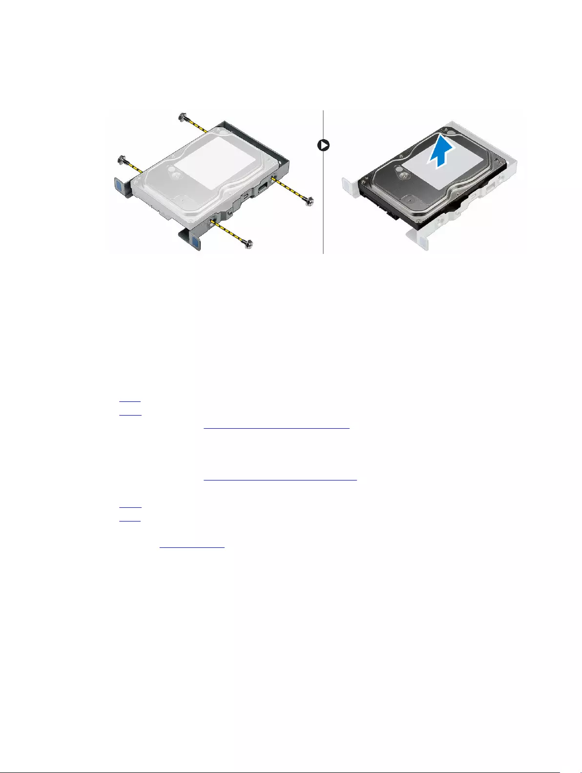
4. To remove the hard drive from the hard drive bracket:
a. Remove the screws that secure the hard-drive bracket to the hard drive.
b. Remove the hard drive from the hard drive bracket.
Installing the hard drive assembly
1. Replace the hard drive into the hard drive bracket.
2. Install the screws that secure the hard drive bracket.
3. Insert the hard drive assembly into the slot on the computer.
4. Close the front bezel door.
5. Install the screw that secures the hard drive assembly to the front bezel door.
6. Connect the SATA cable and the power cable to the connectors on the hard drive.
7. Install the:
•bezel
•cover
8. Follow the procedure in After Working Inside Your Computer.
Removing the optical drive assembly
1. Follow the procedure in Before Working Inside Your Computer.
2. Remove the:
•cover
•bezel
3. To remove the optical drive assembly:
a. Open the front bezel door.
b. Disconnect the data cable and power cable from the connectors on the optical drive assembly [1,
2].
c. Close the front bezel door [3].
d. Remove the screw that secures the optical drive assembly to the computer [4].
e. Slide the optical drive assembly out of the computer [5].
11
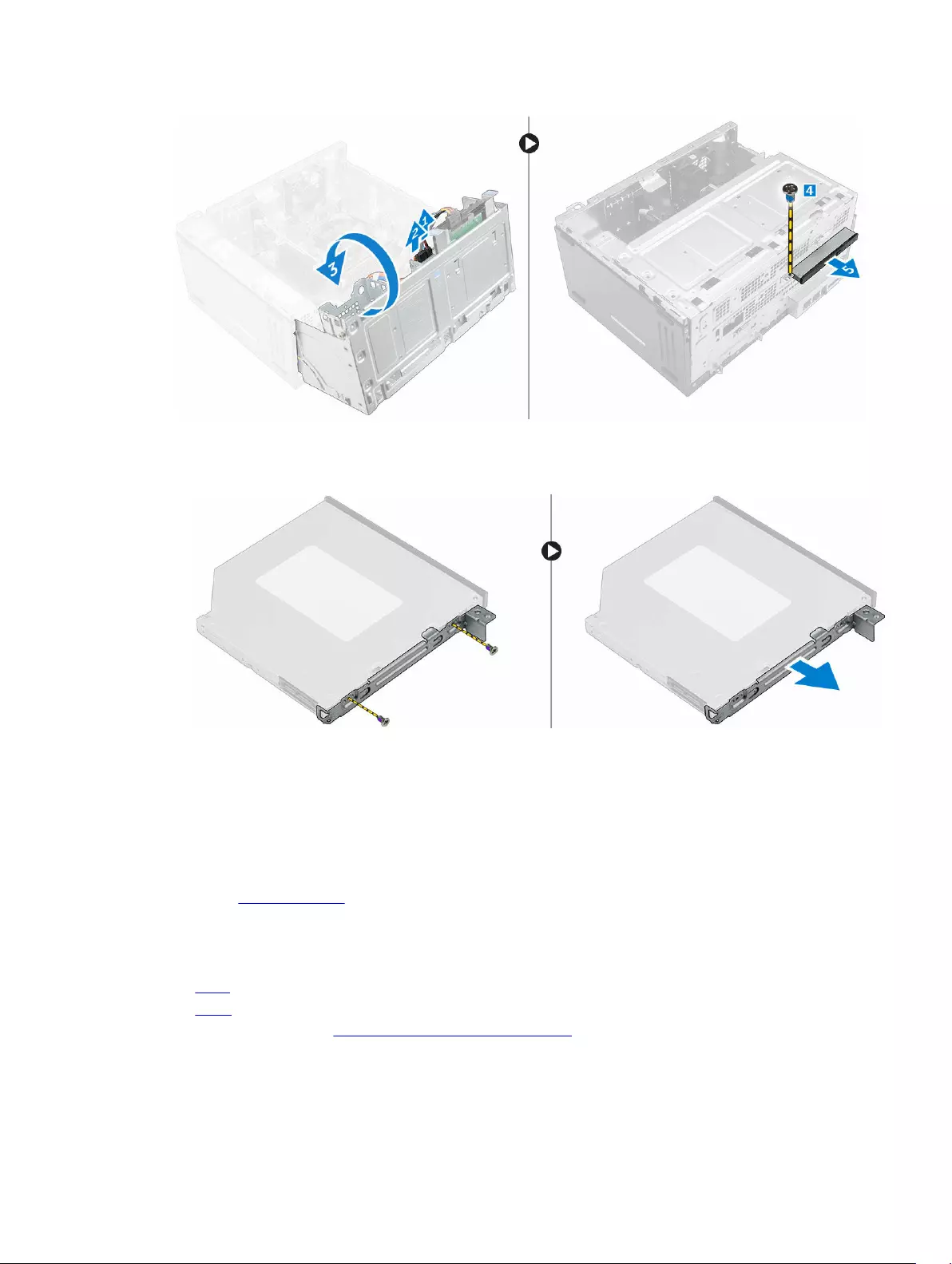
4. To remove the optical drive bracket:
a. Remove the screws that secure the optical drive bracket to the optical drive.
b. Remove the optical drive bracket from the optical drive.
Installing the optical drive assembly
1. Place the optical drive bracket on the optical drive.
2. Tighten the screws to secure the optical drive bracket to the optical drive.
3. Insert the optical drive assembly into the optical drive bay until it clicks into place.
4. Tighten the screw to secure the optical drive assembly to the computer.
5. Open the front bezel door.
6. Connect the data cable and power cable to the connectors on the optical drive assembly .
7. Close the front bezel door.
8. Install the:
•bezel
•cover
9. Follow the procedure in After Working Inside Your Computer.
12
Removing the WLAN card
1. Follow the procedure in Before Working Inside Your Computer.
2. Remove the:
•cover
•bezel
3. Open the front bezel door.
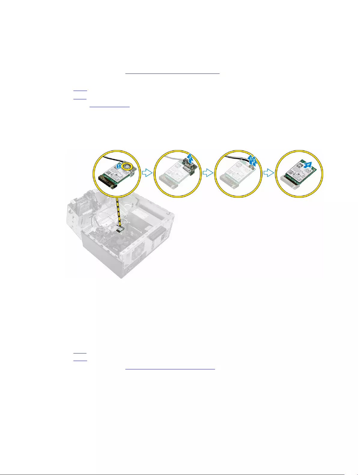
4. To remove the WLAN card:
a. Remove the screw to release the plastic tab that secures the WLAN card to the computer [1].
b. Remove the plastic tab to access the WLAN cables [2].
c. Disconnect the WLAN cables from the connectors on the WLAN card [3].
d. Disconnect the WLAN card from the connector on the system board [4].
Installing the WLAN Card
1. Insert the WLAN card to the connector on the system board.
2. Connect the WLAN cables to the connectors on the WLAN card.
3. Place the plastic tab and tighten the screw to secure the WLAN card to the system board.
4. Close the front bezel door.
5. Install the:
a. bezel
b. cover
6. Follow the procedure in After Working Inside Your Computer.
13
Removing the memory module
1. Follow the procedure in Before Working Inside Your Computer.
2. Remove the:
•cover
•bezel
3. Open the front bezel door.
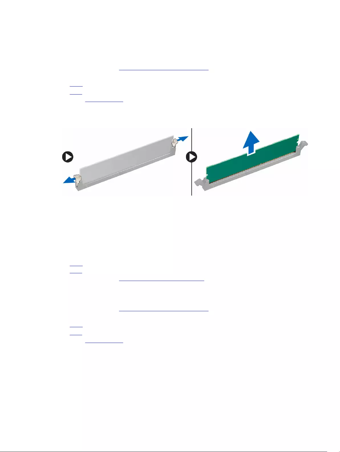
4. To remove the memory module:
a. Press the memory module retention tabs on both sides of the memory module.
b. Lift the memory module from the memory module connector on the system board.
Installing the memory module
1. Align the notch on the memory module with the tab on the memory module connector.
2. Insert the memory module into the memory module socket.
3. Press the memory module until the memory module retention tabs click into place.
4. Close the front bezel door.
5. Install the:
a. cover
b. bezel
6. Follow the procedure in After Working Inside Your Computer.
Removing the PCIe expansion card
1. Follow the procedure in Before Working Inside Your Computer.
2. Remove the:
•cover
•bezel
3. Open the front bezel door.
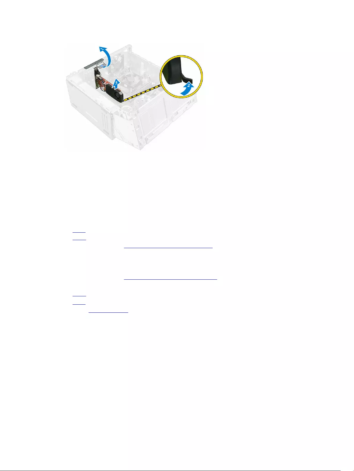
4. To remove the PCIe expansion card:
a. Pull the release latch to unlock the PCIe expansion card [1].
b. Push the release tab [2] and lift the PCIe expansion card out of the computer [3].
14
Installing the PCIe expansion card
1. Pull the release latch to open it.
2. Insert the PCIe expansion card to the connector on the system board.
3. Secure the PCIe expansion card by pushing the card retention latch until it clicks into place.
4. Close the release latch.
5. Close the front bezel door.
6. Install the:
a. bezel
b. cover
7. Follow the procedure in After Working Inside Your Computer.
Removing the power supply unit (PSU)
1. Follow the procedure in Before Working Inside Your Computer.
2. Remove the:
•cover
•bezel
3. Open the front bezel door.
4. To remove the PSU:
a. Remove the screws that secure the PSU to the computer [1].
b. Disconnect the PSU cables from the connectors on the system board [2, 3].
c. Unroute the PSU cables from the retention clips.
d. Press the metal release tab [4], slide and lift the PSU out of the computer [5].
15

Installing the power supply unit (PSU)
1. Insert the PSU into the PSU slot and slide it toward the back of the computer until it clicks into place.
2. Tighten the screws to secure the PSU to the computer.
3. Route the PSU cables through the retention clips.
4. Connect the PSU cables to the connectors on the system board.
5. Close the front bezel door.
6. Install the:
•bezel
•cover
7. Follow the procedure in After Working Inside Your Computer.
Removing the power switch
1. Follow the procedure in Before Working Inside Your Computer.
2. Remove the:
•cover
•bezel
3. Open the front bezel door.
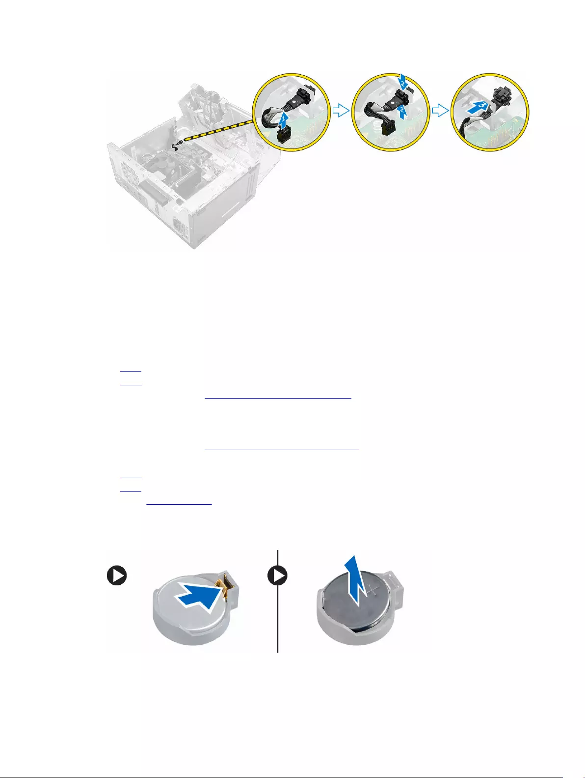
4. To remove the power switch:
a. Disconnect the power switch cable from the system board [1].
b. Unroute the power switch cable from the retention clip.
c. Press the release tab [2] and slide the power switch out of the computer [3].
16
Installing the power switch
1. Insert the power switch into the slot and press it until it clicks into place.
2. Route the power switch cable through the cable retention clip.
3. Connect the power switch cable to the connector on the system board.
4. Close the front bezel door.
5. Install the:
•bezel
•cover
6. Follow the procedure in After Working Inside Your Computer.
Removing the coin cell battery
1. Follow the procedure in Before Working Inside Your Computer.
2. Remove the:
•cover
•bezel
3. Open the front bezel door.
4. To remove the coin cell battery:
a. Press the release latch until the coin cell battery pops out.
b. Remove the coin cell battery from the system board.
17

Installing the coin cell battery
1. Hold the coin cell battery with the «+» sign facing up and slide it under the securing tabs at the
positive side of the connector.
2. Press the battery into the connector until it locks into place.
3. Close the front bezel door.
4. Install the:
•bezel
•cover
5. Follow the procedure in After Working Inside Your Computer.
Removing the heat sink assembly
1. Follow the procedure in Before Working Inside Your Computer.
2. Remove the:
•cover
•bezel
3. Open the front bezel door.
4. To remove the heat sink assembly:
a. Disconnect the heat sink assembly cable from the connector on the system board [1].
b. Loosen the captive screws that secure the heat sink assembly to the system board [2, 3, 4, 5].
c. Lift the heat sink assembly away from the computer [6].
Installing the heat sink assembly
1. Place the heat sink assembly on the processor.
2. Tighten the captive screws to secure the heat sink assembly to the system board.
3. Connect the heat sink assembly cable to the connector on the system board.
4. Close the front bezel door.
5. Install the:
18
•bezel
•cover
6. Follow the procedure in After Working Inside Your Computer.
Removing the processor
1. Follow the procedure in Before Working Inside Your Computer.
2. Remove the:
•cover
•bezel
3. Open the front bezel door.
4. Remove the heat sink assembly.
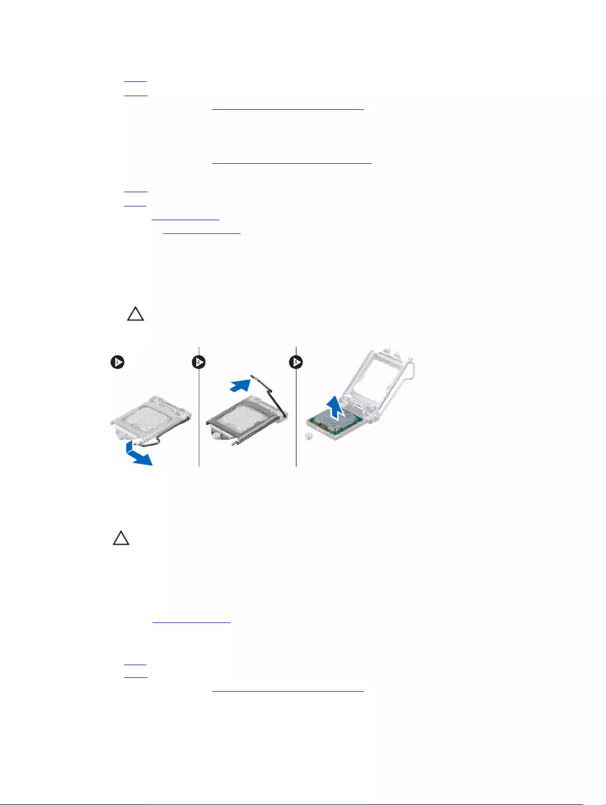
5. To remove the processor:
a. Release the socket lever by pushing the lever down and out from under the tab on the processor
shield [1].
b. Lift the lever upward and lift the processor shield [2].
c. Lift the processor out of the socket [3].
CAUTION: The processor socket pins are fragile and can be permanently damaged. Be
careful not to bend the pins in the processor socket when removing the processor out of
the socket.
Installing the processor
1. Align the processor with the socket keys.
CAUTION: Do not use force to seat the processor. When the processor is positioned
correctly, it engages easily into the socket.
2. Align the pin-1 indicator of the processor with the triangle on the socket.
3. Place the processor on the socket such that the slots on the processor align with the socket keys.
4. Close the processor shield by sliding it under the retention screw.
5. Lower the socket lever and push it under the tab to lock it.
6. Install the heat sink assembly.
7. Close the front bezel door.
8. Install the:
a. bezel
b. cover
9. Follow the procedure in After Working Inside Your Computer.
19
Removing the system fan
1. Follow the procedure in Before Working Inside Your Computer.
2. Remove the:
•cover
•bezel
3. Open the front bezel door.
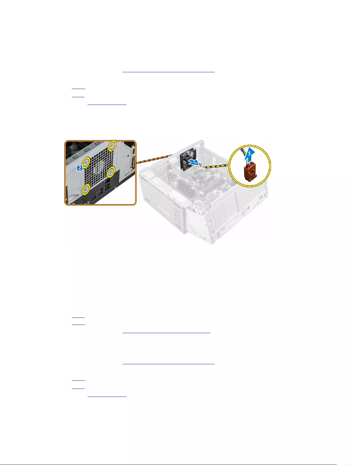
4. To remove the system fan:
a. Disconnect the system fan cable from the connector on the system board [1].
b. Remove the screws that secure the system fan to the computer [2].
c. Slide the system fan out of the computer [3].
Installing the system fan
1. Hold the system fan by the sides with the cable end facing the bottom of the computer.
2. Tighten the screws to secure the system fan to the computer.
3. Connect the system fan cable to the connector on the system board.
4. Close the front bezel door.
5. Install the:
a. bezel
b. cover
6. Follow the procedure in After Working Inside Your Computer.
Removing the system board
1. Follow the procedure in Before Working Inside Your Computer.
2. Remove the:
•cover
•bezel
3. Open the front bezel door.
20
4. Remove the:
•heat sink assembly
•processor
•PCIe expansion card
•memory module
•WLAN card
5. Disconnect all the cables from the connectors on the system board.
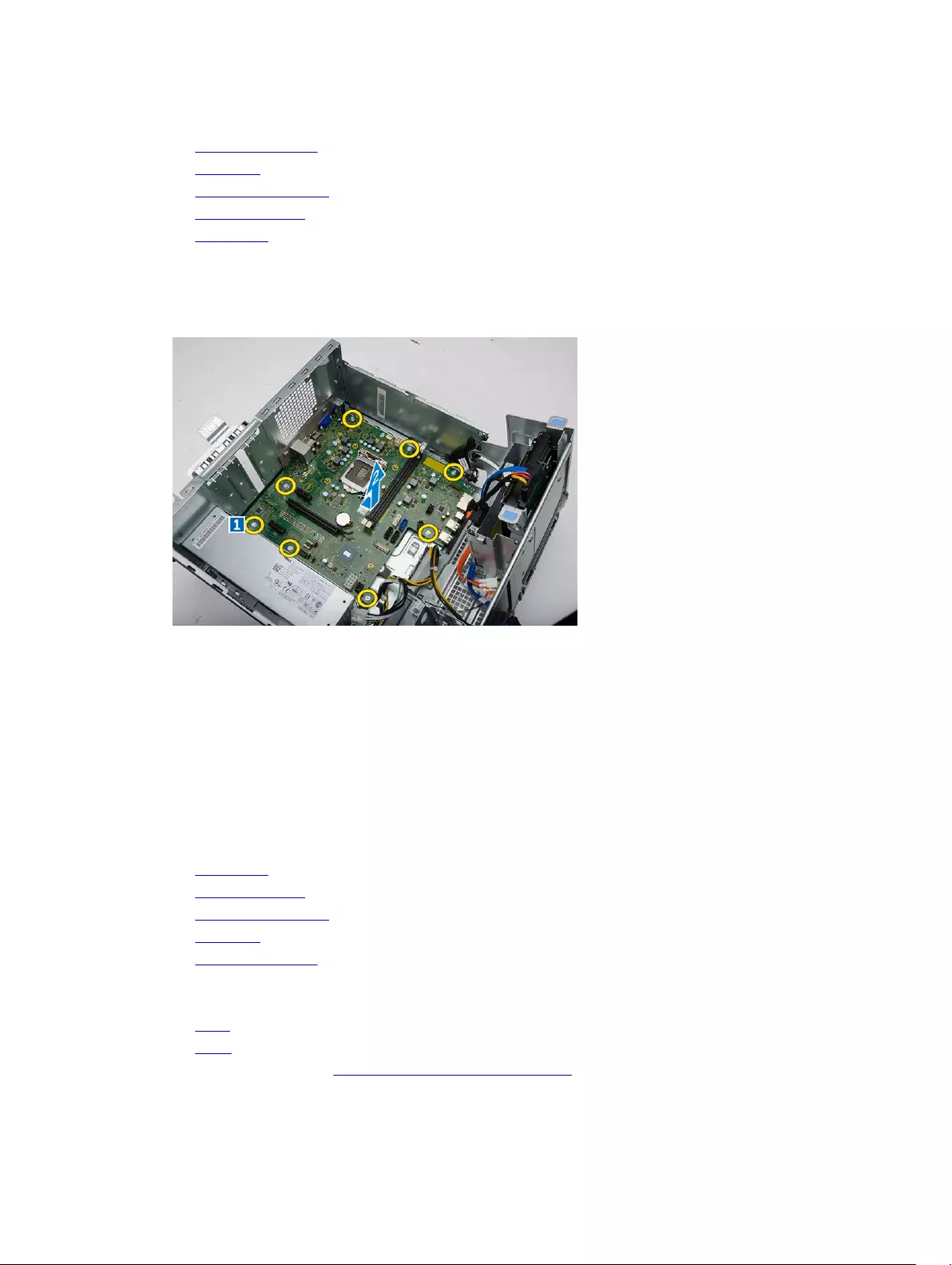
6. To remove the system board:
a. Remove the screws that secure the system board to the computer [1].
b. Slide the system board toward the front of the computer and lift it away from the computer [2].
Installing the system board
1. Hold the system board by its edges and angle it toward the back of the computer.
2. Lower the system board into the computer until the connectors at the back of the system board
align with the slots on the back wall of the computer, and the screw holes on the system board align
with the standoffs on the computer.
3. Tighten the screws to secure the system board to the computer.
4. Route all the cables through the routing channels and connect all the cables to the connectors on
the system board.
5. Install the:
•WLAN card
•memory module
•PCIe expansion card
•processor
•heat sink assembly
6. Close the front bezel door.
7. Install the:
•bezel
•cover
8. Follow the procedure in After Working Inside Your Computer.
21
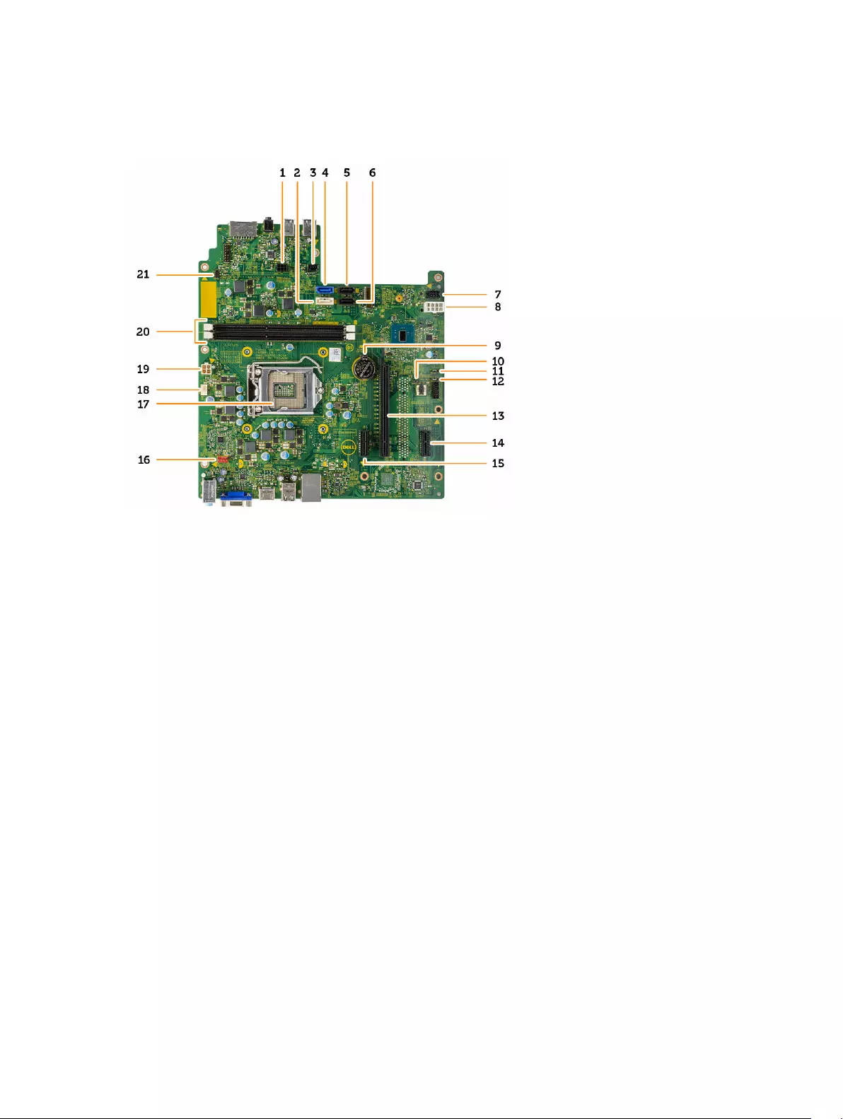
System Board Layout
1. SATA power connector 2. SATA1
3. Light bar header 4. SATA0
5. SATA3 6. SATA2
7. SATA power connector 8. PSU connector
9. Coin cell battery 10. Clear CMS jumper
11. ME disable jumper 12. Password clear jumper
13. PCIex16 14. PCIex1
15. PCIex1 16. System fan connector
17. CPU socket 18. CPU fan connector
19. PSU connector 20. Memory module connectors
21. Power switch connector
22

3
Troubleshooting your computer
You can troubleshoot your computer using indicators like diagnostic lights, beep codes, and error
messages during the operation of the computer.
Diagnostic power LED codes
Table 1. Diagnostic power LED codes
Power LED light status Possible cause Troubleshooting steps
Off The computer is either turned off or
is not receiving power or in
Hibernation mode.
• Re-seat the power cable in the
power connector on the back of
the computer and the electrical
outlet.
• If the computer is plugged into a
power strip, ensure that the
power strip is plugged into an
electrical outlet and is turned on.
Also, bypass power protection
devices, power strips, and power
extension cables to verify that
the computer turns on properly.
• Ensure the electrical outlet is
working by testing it with
another device, such as a lamp.
Steady/Blinking Amber Computer fails to complete POST or
processor failure.
• Remove and reinstall any cards.
• Remove and reinstall the
graphics card, if applicable.
• Ensure the power cable is
connected to the system board
and processor.
Blinking White Light Computer is in sleep mode. • Press the power button to bring
the computer out of the sleep
mode.
• Ensure all power cables are
securely connected to the
system board.
• Ensure the main power cable
and front panel cable are
connected to the system board.
Steady White The computer is fully functional and
in the On state.
If the computer is not responding,
do the following:
• Ensure the display is connected
and turned on.
23

Power LED light status Possible cause Troubleshooting steps
• If the display is connected and
turned on, listen for a beep
code.
Diagnostic error messages
Table 2. Diagnostic error messages
Error messages Description
AUXILIARY DEVICE FAILURE The touchpad or external mouse may be faulty. For
an external mouse, check the cable connection.
Enable the Pointing Device option in the System
Setup program.
BAD COMMAND OR FILE NAME Ensure that you have spelled the command
correctly, put spaces in the proper place, and used
the correct path name.
CACHE DISABLED DUE TO FAILURE The primary cache internal to the microprocessor
has failed. Contact Dell.
CD DRIVE CONTROLLER FAILURE The optical drive does not respond to commands
from the computer.
DATA ERROR The hard drive cannot read the data.
DECREASING AVAILABLE MEMORY One or more memory modules may be faulty or
improperly seated. Reinstall the memory modules
or, if necessary, replace them.
DISK C: FAILED INITIALIZATION The hard drive failed initialization. Run the hard
drive tests in Dell Diagnostics.
DRIVE NOT READY The operation requires a hard drive in the bay
before it can continue. Install a hard drive in the
hard drive bay.
ERROR READING PCMCIA CARD The computer cannot identify the ExpressCard.
Reinsert the card or try another card.
EXTENDED MEMORY SIZE HAS CHANGED The amount of memory recorded in non-volatile
memory (NVRAM) does not match the memory
module installed in the computer. Restart the
computer. If the error appears again, Contact Dell
THE FILE BEING COPIED IS TOO LARGE FOR
THE DESTINATION DRIVE
The file that you are trying to copy is too large to fit
on the disk, or the disk is full. Try copying the file to
a different disk or use a larger capacity disk.
A FILENAME CANNOT CONTAIN ANY OF THE
FOLLOWING CHARACTERS: \ / : * ? » < > |
—
Do not use these characters in filenames.
24

Error messages Description
GATE A20 FAILURE A memory module may be loose. Reinstall the
memory module or, if necessary, replace it.
GENERAL FAILURE The operating system is unable to carry out the
command. The message is usually followed by
specific information. For example, Printer out
of paper. Take the appropriate action.
HARD-DISK DRIVE CONFIGURATION ERROR The computer cannot identify the drive type. Shut
down the computer, remove the hard drive, and
boot the computer from an optical drive. Then,
shut down the computer, reinstall the hard drive,
and restart the computer. Run the Hard Disk Drive
tests in Dell Diagnostics.
HARD-DISK DRIVE CONTROLLER FAILURE 0 The hard drive does not respond to commands
from the computer. Shut down the computer,
remove the hard drive, and boot the computer
from an optical drive. Then, shut down the
computer, reinstall the hard drive, and restart the
computer. If the problem persists, try another
drive. Run the Hard Disk Drive tests in Dell
Diagnostics.
HARD-DISK DRIVE FAILURE The hard drive does not respond to commands
from the computer. Shut down the computer,
remove the hard drive, and boot the computer
from an optical drive. Then, shut down the
computer, reinstall the hard drive, and restart the
computer. If the problem persists, try another
drive. Run the Hard Disk Drive tests in Dell
Diagnostics.
HARD-DISK DRIVE READ FAILURE The hard drive may be defective. Shut down the
computer, remove the hard drive, and boot the
computer from an optical. Then, shut down the
computer, reinstall the hard drive, and restart the
computer. If the problem persists, try another
drive. Run the Hard Disk Drive tests in Dell
Diagnostics.
INSERT BOOTABLE MEDIA The operating system is trying to boot to non-
bootable media, such as an optical drive. Insert
bootable media.
INVALID CONFIGURATION INFORMATION-
PLEASE RUN SYSTEM SETUP PROGRAM
The system configuration information does not
match the hardware configuration. The message is
most likely to occur after a memory module is
installed. Correct the appropriate options in the
system setup program.
25

Error messages Description
KEYBOARD CLOCK LINE FAILURE For external keyboards, check the cable
connection. Run the Keyboard Controller test in
Dell Diagnostics.
KEYBOARD CONTROLLER FAILURE For external keyboards, check the cable
connection. Restart the computer, and avoid
touching the keyboard or the mouse during the
boot routine. Run the Keyboard Controller test in
Dell Diagnostics.
KEYBOARD DATA LINE FAILURE For external keyboards, check the cable
connection. Run the Keyboard Controller test in
Dell Diagnostics.
KEYBOARD STUCK KEY FAILURE For external keyboards or keypads, check the cable
connection. Restart the computer, and avoid
touching the keyboard or keys during the boot
routine. Run the Stuck Key test in Dell Diagnostics.
LICENSED CONTENT IS NOT ACCESSIBLE IN
MEDIADIRECT
Dell MediaDirect cannot verify the Digital Rights
Management (DRM) restrictions on the file, so the
file cannot be played.
MEMORY ADDRESS LINE FAILURE AT ADDRESS,
READ VALUE EXPECTING VALUE
A memory module may be faulty or improperly
seated. Reinstall the memory module or, if
necessary, replace it.
MEMORY ALLOCATION ERROR The software you are attempting to run is
conflicting with the operating system, another
program, or a utility. Shut down the computer, wait
for 30 seconds, and then restart it. Run the
program again. If the error message still appears,
see the software documentation.
MEMORY DOUBLE WORD LOGIC FAILURE AT
ADDRESS, READ VALUE EXPECTING VALUE
A memory module may be faulty or improperly
seated. Reinstall the memory module or, if
necessary, replace it.
MEMORY ODD/EVEN LOGIC FAILURE AT
ADDRESS, READ VALUE EXPECTING VALUE
A memory module may be faulty or improperly
seated. Reinstall the memory module or, if
necessary, replace it.
MEMORY WRITE/READ FAILURE AT ADDRESS,
READ VALUE EXPECTING VALUE
A memory module may be faulty or improperly
seated. Reinstall the memory module or, if
necessary, replace it.
NO BOOT DEVICE AVAILABLE The computer cannot find the hard drive. If the
hard drive is your boot device, ensure that the drive
is installed, properly seated, and partitioned as a
boot device.
NO BOOT SECTOR ON HARD DRIVE The operating system may be corrupted, Contact
Dell.
26

Error messages Description
NO TIMER TICK INTERRUPT A chip on the system board may be
malfunctioning. Run the System Set tests in Dell
Diagnostics.
NOT ENOUGH MEMORY OR RESOURCES. EXIT
SOME PROGRAMS AND TRY AGAIN
You have too many programs open. Close all
windows and open the program that you want to
use.
OPERATING SYSTEM NOT FOUND Reinstall the hard drive. If the problem persists,
Contact Dell.
OPTIONAL ROM BAD CHECKSUM The optional ROM has failed. Contact Dell.
SECTOR NOT FOUND The operating system cannot locate a sector on
the hard drive. You may have a defective sector or
corrupted File Allocation Table (FAT) on the hard
drive. Run the Windows error-checking utility to
check the file structure on the hard drive. See
Windows Help and Support for instructions (click
Start → Help and Support). If a large number of
sectors are defective, back up the data (if possible),
and then format the hard drive.
SEEK ERROR The operating system cannot find a specific track
on the hard drive.
SHUTDOWN FAILURE A chip on the system board may be
malfunctioning. Run the System Set tests in Dell
Diagnostics. If the message reappears, Contact
Dell.
TIME-OF-DAY CLOCK LOST POWER System configuration settings are corrupted.
Connect your computer to an electrical outlet to
charge the battery. If the problem persists, try to
restore the data by entering the System Setup
program, then immediately exit the program. If the
message reappears, Contact Dell.
TIME-OF-DAY CLOCK STOPPED The reserve battery that supports the system
configuration settings may require recharging.
Connect your computer to an electrical outlet to
charge the battery. If the problem persists, Contact
Dell.
TIME-OF-DAY NOT SET-PLEASE RUN THE
SYSTEM SETUP PROGRAM
The time or date stored in the system setup
program does not match the system clock. Correct
the settings for the Date and Time options.
TIMER CHIP COUNTER 2 FAILED A chip on the system board may be
malfunctioning. Run the System Set tests in Dell
Diagnostics.
UNEXPECTED INTERRUPT IN PROTECTED MODE The keyboard controller may be malfunctioning, or
a memory module may be loose. Run the System
27

Error messages Description
Memory tests and the Keyboard Controller test in
Dell Diagnostics or Contact Dell.
X:\ IS NOT ACCESSIBLE. THE DEVICE IS
NOT READY
Insert a disk into the drive and try again.
System error messages
Table 3. System error messages
System message Description
Alert! Previous attempts at booting
this system have failed at checkpoint
[nnnn]. For help in resolving this
problem, please note this checkpoint
and contact Dell Technical Support
The computer failed to complete the boot routine
three consecutive times for the same error.
CMOS checksum error RTC is reset, BIOS Setup default has been loaded.
CPU fan failure CPU fan has failed.
System fan failure System fan has failed.
Hard-disk drive failure Possible hard disk drive failure during POST.
Keyboard failure Keyboard failure or loose cable. If reseating the
cable does not solve the problem, replace the
keyboard.
No boot device available No bootable partition on hard disk drive, the hard
disk drive cable is loose, or no bootable device
exists.
• If the hard drive is your boot device, ensure that
the cables are connected and that the drive is
installed properly and partitioned as a boot
device.
• Enter system setup and ensure that the boot
sequence information is correct.
No timer tick interrupt A chip on the system board might be
malfunctioning or motherboard failure.
NOTICE — Hard Drive SELF MONITORING
SYSTEM has reported that a parameter
has exceeded its normal operating
range. Dell recommends that you back up
your data regularly. A parameter out of
range may or may not indicate a
potential hard drive problem
S.M.A.R.T error, possible hard disk drive failure.
28

4
System Setup Options
Table 4. — Main
System Time Displays the system time. Allows you to reset the time on the
computer’s internal clock.
System Date Displays the system date. Allows you to reset the date on the
computer’s internal calendar.
BIOS Version Displays the BIOS revision.
Product Name Displays the computer model number.
Service Tag Displays the service tag of your computer.
Asset Tag Displays the asset tag of your computer (if available).
CPU Type Displays the type of processor.
CPU Speed Displays the speed of the processor
CPU ID Displays the processor ID
CPU Cache Displays the L1, L2, and L3 cache size of the processor.
HDD0 Displays the HDD0 size of the computer.
HDD1 Displays the HDD1 size of the computer.
HDD2 Displays the HDD2 size of the computer.
HDD3 Displays the HDD3 size of the computer.
System Memory Displays the size of the memory installed.
Memory Speed Displays the speed of the memory installed.
Table 5. — Advanced
Intel (R) SpeedStep (TM) Allows you to enable or disable the Intel SpeedStep technology.
Default: Enabled
Virtualization Allows you to enable or disable the virtualization feature.
Default: Enabled
VT for Direct I/O Allows you to enable or disable the VT for direct I/O.
Default: Enabled
Trusted Execution Allows you to enable or disable the trusted execution.
Default: Disabled
Integrated NIC Allows you to enable to disable the integrated network
29

Default: Enabled
SATA Operation Allows you to change the SATA mode
Default: AHCI
Intel Multi-Display Allows you to enable or disable the multi-display feature.
Default: disabled
USB Emulation Allows you to enable or disable the USB emulation.
Default: Enabled
SW Guard Extensions (SGX) Allows you to enable or disable the SW guard extensions (SGX).
Default: Disabled
USB Configuration Allows you to enable or disable the USB ports.
Front USB Ports: Enabled
Rear USB Ports: Enabled
Power Options Allows you to modify the power options.
Wake up by Integrated LAN/WLAN: Disabled
AC Recovery: Power Off
Deep Sleep Control: Enabled in S4 and S5 modes
Auto Power On: Disabled
Auto Power On Mode: Allows you to select the day (Default:
disabled)
Auto Power On Date: Allows you to select the date
Auto Power On Time: Allows you to select the time
SMART Settings Allows you to enable to enable or disable the SMART feature.
Default: Disabled
Table 6. — Security
Unlock Setup Status Allows you to lock or unlock the system setup.
Default: Unlocked
Admin Password Status Displays the status indicating if the Administrator
password is set.
Default: Not Set
System Password Status Displays the status indicating if the System
password is set.
Default: Not Set
HDD Password Status Displays the status indicating if the System
password is set.
30

Default: Not Set
Asset Tag Allows you to enter your service tag.
Admin Password Allows you to create an admin password.
HDD Password Allows you to create an HDD password.
System Password Allows you to create a system password.
Password Change Allows you to set the option to change password.
Default: Permitted
Firmware TPM Allows you to enable or disable the Firmware TPM.
Default: Disabled
HDD Protection Allows to modify the HDD protection feature.
Default: Disabled
Table 7. — Boot
Boot List Option Displays the boot modes
Default: UEFI
File Browser Add Boot Option and File Browser Del
Boot Option are actiavted
Secure Boot Allows you to enable or disable the Secure Boot
control.
Default: Enabled
Legacy Option ROMs Allows you to load the legacy option ROMs.
Default: Disabled
Boot Option Priorities Enables you to change the boot option priorities.
Table 8. — Exit
Save Changes and Reset Allows to save or rest the changes made to the
system setup.
1. Allows you to discard the changes made to
the system setup.
2. Allows you to restore the system setup
options to default.
3. Allows you to discard the changes made to
the system setup.
4. Allows you to save the changes made to the
system setup.
System Setup overview
System Setup allows you to:
31

• Change the system configuration information after you add, change, or remove any hardware in your
computer.
• Set or change a user-selectable option such as the user password.
• Read the current amount of memory or set the type of hard drive installed.
Before you use System Setup, it is recommended that you write down the System Setup screen
information for future reference.
CAUTION: Unless you are an expert computer user, do not change the settings for this program.
Certain changes can cause your computer to work incorrectly.
Accessing System Setup
1. Turn on (or restart) your computer.
2. After the white Dell logo appears, press F2 or F12 immediately.
The System Setup page is displayed.
NOTE: If you wait too long and the operating system logo appears, wait until you see the
desktop. Then, shut down or restart your computer and try again.
32

5
Specifications
NOTE: Offerings may vary by region. The following specifications are only those required by law to
ship with your computer. For more information about the configuration of your computer, go to
Help and Support in your Windows operating system and select the option to view information
about your computer.
Table 9. Processor
Type • Intel Celeron
• Intel Pentium
• Intel Dual Core i3 (6th Generation)
• Intel Dual Core i5 (6th Generation)
• Intel Dual Core i7 (6th Generation)
Table 10. Memory
Memory-module connector Two UDIMM slots
Memory-module capacity 2 GB, 4 GB, and 8 GB
Type 1600 MHz DDR3L (Non-ECC)
Minimum memory 2 GB
NOTE: Depending on the operating system
installed, the requirement of the minimum
memory might vary.
Maximum memory 16 GB
NOTE: Each UDIMM slot supports maximum of
8 GB memory.
Table 11. Video
Video type:
Integrated Intel HD Graphics
Discrete PCI Express x16 graphics card
• Nvidia GT 705
• AMD R9 360
Integrated video memory Shared system memory
33

Table 12. Audio
Integrated Integrated 5.1 channel High Definition Audio
Table 13. Communication
Ethernet 10/100/1000 Mbps Ethernet controller integrated on system board
Wireless Up to Wi-Fi 802.11ac
Bluetooth 4.0
Table 14. System Information
Chipset Intel H110
Table 15. Expansion Bus
Bus speed:
PCI Express PCIe 2.0 at speeds upto 5.0 GT/s
SATA • SATA 3 Gbps for optical drive
• SATA 6 Gbps for hard drive
USB • 5 Gbps for USB 3.0
• 480 Mbps for USB 2.0
Table 16. Cards
PCIe x16 One full height card
PCIe x1 Up to two full height cards
M2 Slot One M.2 card slot for Wi-Fi and Bluetooth combo
card
Table 17. Drives
2.5 inch drive bays Up to two
3.5 inch drive bays One
5.25 inch optical-drive bays One
Table 18. External Connectors
Audio:
Back panel Three connectors
Front Panel One headset port
Network One RJ-45 connector
USB:
Front panel Two USB 3.0 connectors
34

Back panel Four USB 2.0 connectors
Video • One 15-hole VGA connector
• One 19-pin HDMI connector
Memory-card reader one
Table 19. Control Lights And Diagnostic Lights
Power button light white light — solid white light indicates power-on
state ; blinking white light indicates sleep/stand-by
state of the computer.
amber light — solid amber light indicates boot failure
— System Power Error; blinking amber light indicates
boot failure — System Power OK
Drive activity light white light — blinking white light indicates that the
computer is reading data from, or writing data to the
hard drive.
Table 20. Power
Coin cell battery 3 V CR2032 lithium coin cell
Input voltage 200-240 VAC / 100-127/200-240 VAC / 100-240
VAC
Input frequency 50 Hz to 60 Hz
Wattage 240 W
Input current 2 A / 7/3.5A / 4 A
Maximum heat dissipation 820 BTU/hr
NOTE: Heat dissipation is calculated by using the power supply wattage rating.
Table 21. Physical
Height 380 mm (14.96 inches)
Width 175 mm (6.88 inches)
Depth 436.3 mm (17.17 inches)
Weight (Minimum) 8.5 kg (18.73 lb)
Table 22. Environmental
Temperature:
Operating 10 °C to 35 °C (50 °F to 95 °F)
Storage –40 °C to 65 °C (–40 °F to 149 °F)
Relative humidity 20 % to 80 % (non-condensing)
35

Altitude:
Operating –15.20 m to 3048 m (–50 ft to 10,000 ft)
Storage –15.20 m to 10,668 m (–50 ft to 35,000 ft)
Airborne contaminant level G1 as defined by ISA-S71.04–1985
36

6
Contacting Dell
NOTE: If you do not have an active Internet connection, you can find contact information on your
purchase invoice, packing slip, bill, or Dell product catalog.
Dell provides several online and telephone-based support and service options. Availability varies by
country and product, and some services may not be available in your area. To contact Dell for sales,
technical support, or customer service issues:
1. Go to Dell.com/support.
2. Select your support category.
3. Verify your country or region in the Choose a Country/Region drop-down list at the bottom of the
page.
4. Select the appropriate service or support link based on your need.
37
Owner’s Manual
33 pages
en
Quick Start Guide
2 pages
Dell Vostro 3650 Desktop Specification
The Dell Vostro 3650 Desktop is designed for small businesses seeking a reliable, space-saving solution. It features a compact mini-tower design, providing ample performance without occupying excessive desk space. Powered by Intel Core processors, it offers a range of options from the i3 to i7 series, ensuring efficient multitasking capabilities. The desktop supports up to 16GB of DDR3L RAM, catering to various business needs and enhancing overall system responsiveness. Storage options include a traditional HDD with capacities up to 1TB or a faster SSD, allowing users to balance between storage space and speed. Integrated Intel HD Graphics or optional discrete AMD Radeon R5 340X graphics deliver competent visual performance for everyday tasks and light multimedia applications. Connectivity is robust, with multiple USB 3.0 and USB 2.0 ports, HDMI and VGA outputs for dual-monitor setups, and an Ethernet port for stable network connections. The system also supports wireless connectivity through an optional Wi-Fi card. The Vostro 3650 comes pre-installed with Windows 10 Pro, providing a user-friendly interface and advanced security features suitable for business environments. Its tool-less chassis design facilitates easy access to internal components, simplifying upgrades and maintenance. The desktop is equipped with a DVD-RW drive for additional media handling capabilities. With a focus on reliability, it incorporates Dell’s security and support services, including TPM 2.0 for data protection and optional ProSupport for enhanced technical assistance. The Vostro 3650 balances performance, connectivity, and manageability, making it an ideal choice for small businesses looking for an efficient and cost-effective computing solution.
Dell Vostro 3650 Desktop F.A.Q.
To upgrade the RAM on your Dell Vostro 3650, first power off and unplug the desktop. Open the side panel by removing the screws at the back. Locate the RAM slots on the motherboard and insert the new RAM module into an available slot, ensuring it clicks into place. Replace the side panel and power on the system to check if the system recognizes the new RAM.
If your Dell Vostro 3650 is not turning on, check the power cable and ensure it is securely connected to both the desktop and the power outlet. Confirm the outlet is working by testing with another device. If the issue persists, try resetting the power supply by disconnecting the power cable, pressing and holding the power button for 15 seconds, then reconnecting the power cable and trying again.
To perform a factory reset on your Dell Vostro 3650, restart the computer and press F8 multiple times until the Advanced Boot Options menu appears. Select «Repair Your Computer» and press Enter. Follow the on-screen instructions to perform a factory reset. Ensure you backup important data before proceeding, as this process will erase all data on the hard drive.
Your Dell Vostro 3650 may be running slow due to insufficient RAM, a cluttered hard drive, or malware. Consider upgrading your RAM, removing unnecessary files and programs, and running a full system antivirus scan. Additionally, check for any pending system updates that may improve performance.
To connect dual monitors, ensure your Dell Vostro 3650 has a graphics card that supports multiple displays. Connect each monitor to the available video output ports (HDMI, VGA, DVI, or DisplayPort) on your computer. Once connected, right-click on the desktop, select «Display settings», and configure the display arrangement according to your preference.
The Dell Vostro 3650 supports a maximum RAM capacity of 16GB. It has two DIMM slots, each capable of holding up to 8GB of DDR3L RAM. Ensure that the RAM you purchase is compatible with the system specifications.
To update the BIOS on your Dell Vostro 3650, visit the Dell Support website and locate the latest BIOS update for your model. Download the BIOS update file and follow the included instructions to install it. Ensure your computer is connected to a reliable power source during the update process to prevent any interruptions.
If your Dell Vostro 3650 is overheating, ensure the cooling vents are not blocked and clean them with compressed air if necessary. Verify that all fans are operational. Consider applying new thermal paste to the CPU if overheating persists. Also, ensure the system is not placed in an enclosed space that limits airflow.
To troubleshoot audio problems, first check the volume settings and ensure the audio output is set to the correct device. Update the audio drivers via the Device Manager. If the issue continues, run the Windows Troubleshooter by going to Settings > Update & Security > Troubleshoot, and selecting «Playing Audio».
Regular maintenance for your Dell Vostro 3650 includes keeping the system and drivers updated, running antivirus scans, cleaning physical dust from the vents and components, checking for disk errors, and ensuring the operating system is optimized by removing unnecessary startup programs.