
Manual
View the manual for the Gigabyte GA-K8N-SLI here, for free. This user manual comes under the category motherboards and has been rated by 1 people with an average of a 7.5. This manual is available in the following languages: English. Do you have a question about the Gigabyte GA-K8N-SLI?
Ask your question here
Gigabyte GA-K8N-SLI specifications
Below you will find the product specifications and the manual specifications of the Gigabyte GA-K8N-SLI.
Maximum internal memory
4 GB
Processor manufacturer
AMD
Number of SATA connectors
4
Floppy disk drive connector
Yes
Parallel ports quantity
1
Motherboard form factor
ATX
General
| Brand | Gigabyte |
| Model | GA-K8N-SLI | GA-K8N-SLI |
| Product | motherboard |
| EAN | 4719331831066 |
| Language | English |
| Filetype | User manual (PDF), Installation Guide (PDF) |
Memory
| Maximum internal memory | 4 GB |
| Number of memory slots | 4 |
Processor
| Processor manufacturer | AMD |
| Processor socket | Socket 939 |
| Processor system buses supported | 2000 MHz |
Internal I/O
| Number of SATA connectors | 4 |
| USB 2.0 connectors | 3 |
| CD/AUX audio in | Yes |
Other features
| Floppy disk drive connector | Yes |
| Dimensions (WxDxH) | 305 x 244 mm |
Rear panel I/O ports
| Parallel ports quantity | 1 |
| Serial ports quantity | 1 |
| PS/2 ports quantity | 2 |
| USB 2.0 ports quantity | 4 |
| Ethernet LAN (RJ-45) ports | 1 |
| Headphone outputs | 1 |
| Microphone in | Yes |
| S/PDIF out port | Yes |
Features
| Motherboard form factor | ATX |
| Audio chip | Realtek ALC850 |
| Power source type | ATX |
Network
| Networking features | CICADA 8201 |
Expansion slots
| Expansion slots | 2 x PCI-Express X 16 \n2 x PCI-Express X 1 \n2 x PCI\n |
Weight & dimensions
show more
Frequently asked questions
Can’t find the answer to your question in the manual? You may find the answer to your question in the FAQs about the Gigabyte GA-K8N-SLI below.
What is the width of the Gigabyte GA-K8N-SLI?
The Gigabyte GA-K8N-SLI has a width of 305 mm.
What is the depth of the Gigabyte GA-K8N-SLI?
The Gigabyte GA-K8N-SLI has a depth of 244 mm.
Is the manual of the Gigabyte GA-K8N-SLI available in English?
Yes, the manual of the Gigabyte GA-K8N-SLI is available in English .
Is your question not listed? Ask your question here
Manuals.eu
- Manuals.eu
- Gigabyte
- Computers & Peripherals
- Mainboards
- Socket 775
- NVIDIA nForce4 SLI
- GA-K8N-SLI (rev. 1.x)
- Manual
×
1
2
3
4
5
6
7
8
9
10
11
12
13
14
15
16
17
18
19
20
21
22
23
24
25
26
27
28
29
30
31
32
33
34
35
36
37
38
39
40
41
42
43
44
45
46
47
48
49
50
51
52
53
54
55
56
57
58
59
60
61
62
63
64
65
66
67
68
69
70
71
72
73
74
75
76
77
78
79
80
81
82
83
84
85
86
87
88
⟨
⟩
Copyright © Manuals.eu
Agreement
Privacy Policy
Contact us
Скачать
GA-K8N Ultra-SLI /
GA-K8N Pro-SLI /
GA-K8N-SLI
AMD Socket 939 Processor Motherboard
User’s Manual
Rev. 1004
12ME-K8NUSLI-1004

GA-K8N Ultra-SLI /
GA-K8N Pro-SLI /
GA-K8N-SLI
AMD Socket 939 Processor Motherboard
User’s Manual
Rev. 1004
12ME-K8NUSLI-1004

Jan. 12, 2005
GA-K8N Ultra-SLI
Motherboard
Jan. 12, 2005
GA-K8N Ultra-SLI
Motherboard

Feb. 25, 2005
GA-K8N Pro-SLI
Motherboard
Feb. 25, 2005
GA-K8N Pro-SLI
Motherboard

Aug. 8, 2005
Motherboard
GA-K8N-SLI
Aug. 8, 2005
GA-K8N-SLI
Motherboard

Copyright
© 2006 GIGA-BYTE TECHNOLOGY CO., LTD. All rights reserved.
The trademarks mentioned in the manual are legally registered to their respective companies.
Notice
The written content provided with this product is the property of Gigabyte.
No part of this manual may be reproduced, copied, translated, or transmitted in any form or by any
means without Gigabyte’s prior written permission. Specifications and features are subject to
change without prior notice.
Product Manual Classification
In order to assist in the use of this product, Gigabyte has categorized the user manual in the
following:
For quick installation, please refer to the «Hardware Installation Guide» included with the
product.
For detailed product information and specifications, please carefully read the
«Product User Manual».
For detailed information related to Gigabyte’s unique features, please go to the
«Technology Guide» section on Gigabyte’s website to read or download the information
you need.
For more product details, please click onto Gigabyte’s website at www.gigabyte.com.tw

Table of Contents
GA-K8N Ultra-SLI / GA-K8N Pro-SLI / GA-K8N-SLI Motherboard Layout ………………… 8
Block Diagram …………………………………………………………………………………………………. 9
Chapter 1 Hardware Installation ………………………………………………………………………..11
1-1 Considerations Prior to Installation …………………………………………………………. 11
1-2 Feature Summary ……………………………………………………………………………… 12
1-3 Installation of the CPU and Fan Heat Sink …………………………………………….. 14
1-3-1 Installation of the CPU …………………………………………………………………………….. 14
1-3-2 Installation of the Fan Heat Sink ……………………………………………………………… 15
1-4 Installation of Memory ………………………………………………………………………… 16
1-5 Installation of Expansion Cards ……………………………………………………………. 18
1-6 Setup of SLI (Scalable Link Interface) Configuration ………………………………… 19
1-7 I/O Back Panel Introduction ………………………………………………………………… 22
1-8 Connectors Introduction ………………………………………………………………………. 23
Chapter 2 BIOS Setup…………………………………………………………………………………… 33
The Main Menu (For example: BIOS Ver. : F6a)……………………………………………… 34
2-1 Standard CMOS Features ………………………………………………………………….. 36
2-2 Advanced BIOS Features …………………………………………………………………… 38
2-3 Integrated Peripherals …………………………………………………………………………. 40
2-4 Power Management Setup ………………………………………………………………….. 44
2-5 PnP/PCI Configurations ……………………………………………………………………… 45
2-6 PC Health Status ………………………………………………………………………………. 46
2-7 MB Intelligent Tweaker(M.I.T.) …………………………………………………………….. 49
2-8 Top Performance ………………………………………………………………………………… 52
2-9 Load Optimized Defaults ……………………………………………………………………… 52
2-10 Set Supervisor/User Password …………………………………………………………… 53
2-11 Save & Exit Setup …………………………………………………………………………….. 54
2-12 Exit Without Saving …………………………………………………………………………… 54
— 6 —

Chapter 3 Drivers Installation ………………………………………………………………………….. 55
3-1 Install Chipset Drivers ………………………………………………………………………… 55
3-2 Software Application …………………………………………………………………………… 56
3-3 Software Information …………………………………………………………………………… 56
3-4 Hardware Information …………………………………………………………………………. 57
3-5 Contact Us ……………………………………………………………………………………….. 57
Chapter 4 Appendix ……………………………………………………………………………………… 59
4-1 Unique Software Utilities …………………………………………………………………….. 59
4-1-1 EasyTune 5 Introduction …………………………………………………………………………. 59
4-1-2 Xpress Recovery2 Introduction ………………………………………………………………. 60
4-1-3 Flash BIOS Method Introduction ……………………………………………………………… 62
4-1-4 Serial ATA BIOS Setting Utility Introduction ……………………………………………… 73
4-1-5 2- / 4- / 6- / 8- Channel Audio Function Introduction ……………………………….. 79
4-2 Troubleshooting ………………………………………………………………………………….. 85
— 7 —
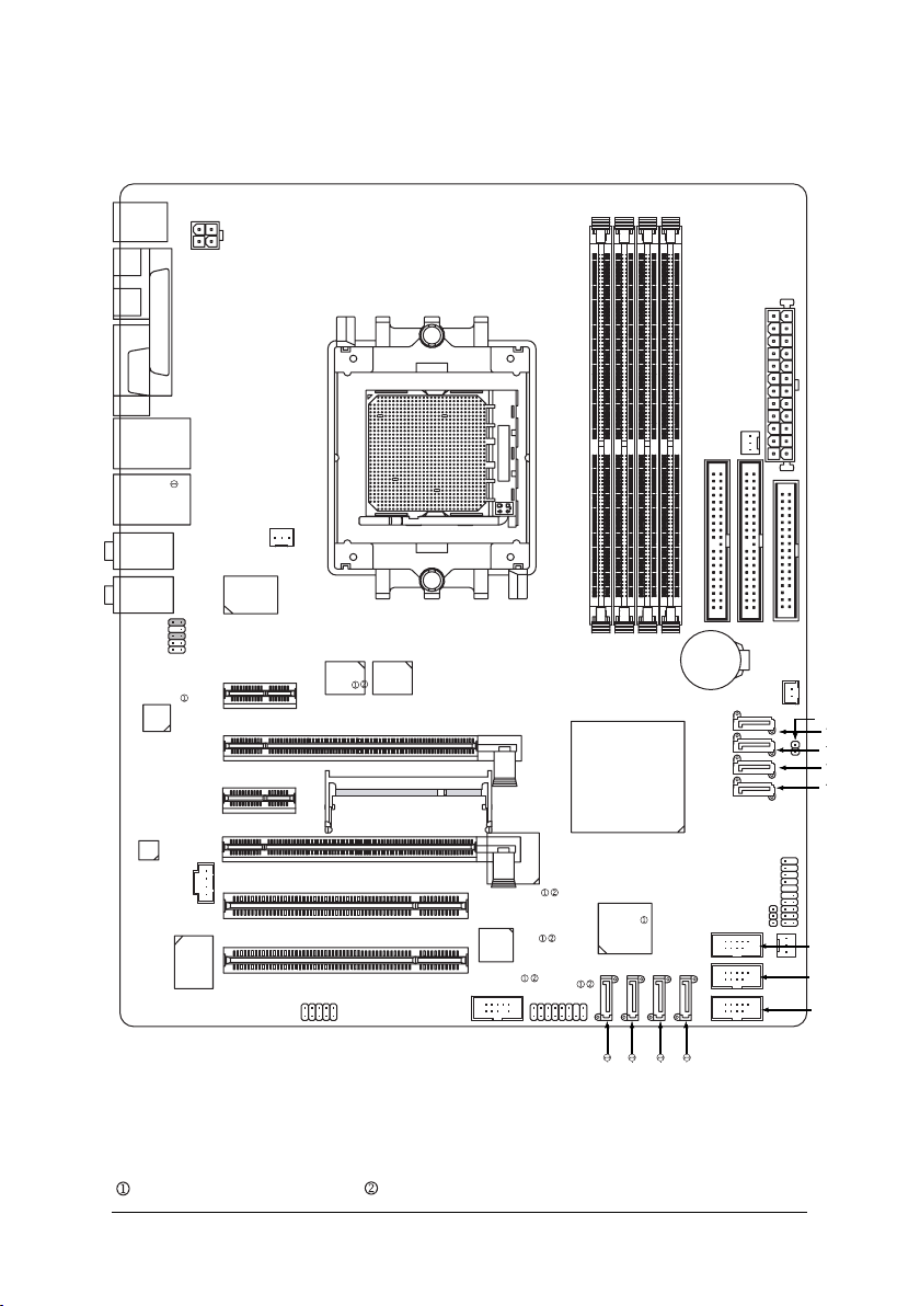
GA-K8N Ultra-SLI / GA-K8N Pro-SLI / GA-K8N-SLI Motherboard Layout
DDR1
DDR2
DDR3
KB_MS
DDR4
SPDIF_I
SPDIF_O
COMA
USB
USB
AUDIO1
AUDIO2
F_AUDIO
Marvell
8053
CODEC
LPT
LAN2
LAN1
ATX_12V
CD_IN
IT8712
VITESSE
8201 phy
PCIE_1
PCIE_2
CPU_FAN
Socket 939
Backup
Main
BIOS
BIOS
PCIE_16_1
SLI Switch Module Socket
PCIE_16_2
PCI1
PCI2
IR_CIR
TSB82AA2
TSB81BA3
F1_1394
ATX
PWR_FAN
IDE2
FDD
GA-K8N Ultra-SLI or GA-K8N Pro-SLI/GA-K8N-SLI
®
nVIDIA
nForce4 SLI
Sil3114
F2_1394
BATTERY
PWR_LED
IDE1
F_PANEL
NB_FAN
SYS_FAN
CLR_CMOS
S_ATA1_SB
S_ATA0_SB
S_ATA3_SB
S_ATA2_SB
F_USB3
F_USB2
F_USB1
Only for GA-K8N Ultra-SLI. Only for GA-K8N Pro-SLI.
— 8 —
SATA1_SII
SATA0_SII
SATA3_SII
SATA2_SII
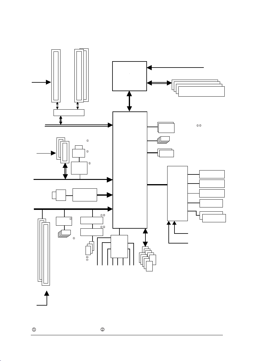
Block Diagram
1 PCIE x 16
PCI-ECLK
(100MHz)
Normal Mode
2 PCI Express x 1 Ports
PCI-ECLK
(100MHz)
or
SLI Switch
PCI Express x 16 Bus
PCI Express x 1 Bus
RJ45
LAN 2
PCI Bus
Sil3114
4 SATA
2 PCIE x 8
SLI Mode
LAN 1
RJ45
Marvell
8053
VITESSE
8201 phy
TSB82AA2
TSB81BA3
AMD K8
Socket 939
nForce4
CODEC
CPU
Hyper Transport Bus
®
nVIDIA
SLI
CPUCLK+/-(200MHz)
DDR 400/333/266/200MHz DIMM
Dual Channel Memory
Dual BIOS
4 SATA 3Gb/s
ATA33/66/100/133
IDE Channels
LPC BUS
IT8712
24MHz
33MHz
IR_CIR
Floppy
LPT Port
COM Port
PS/2 KB/Mouse
MIC
2PCI
PCICLK
(33MHz)
Only for GA-K8N Ultra-SLI. Only for GA-K8N Pro-SLI.
3 IEEE1394b
Surround Speaker Out
Line-Out
Side Speaker Out
Center/Subwoofer Spear Out
Line-In
— 9 —
10 USB
Ports
SPDIF In
SPDIF Out

— 10 —

Chapter 1Hardware Installation
1-1 Considerations Prior to Installation
Preparing Your Computer
The motherboard contains numerous delicate electronic circuits and components which can
become damaged as a result of electrostatic discharge (ESD). Thus, prior to installation, please
follow the instructions below:
1. Please turn off the computer and unplug its power cord.
2. When handling the motherboard, avoid touching any metal leads or connectors.
3. It is best to wear an electrostatic discharge (ESD) cuff when handling electronic components
(CPU, RAM).
4. Prior to installing the electronic components, please have these items on top of an antistatic
pad or within a electrostatic shielding container.
5. Please verify that the power supply is switched off before unplugging the power supply
connector from the motherboard.
Installation Notices
1. Prior to installation, please do not remove the stickers on the motherboard. These stickers
are required for warranty validation.
2. Prior to the installation of the motherboard or any hardware, please first carefully read the
information in the provided manual.
3. Before using the product, please verify that all cables and power connectors are connected.
4. To prevent damage to the motherboard, please do not allow screws to come in contact with
the motherboard circuit or its components.
5. Please make sure there are no leftover screws or metal components placed on the motherboard
or within the computer casing.
6. Please do not place the computer system on an uneven surface.
7. Turning on the computer power during the installation process can lead to damage to system
components as well as physical harm to the user.
8. If you are uncertain about any installation steps or have a problem related to the use of the
product, please consult a certified computer technician.
English
Instances of Non-Warranty
1. Damage due to natural disaster, accident or human cause.
2. Damage as a result of violating the conditions recommended in the user manual.
3. Damage due to improper installation.
4. Damage due to use of uncertified components.
5. Damage due to use exceeding the permitted parameters.
6. Product determined to be an unofficial Gigabyte product.
Hardware Installation— 11 —

English
1-2 Feature Summary
Motherboard GA-K8N Ultra-SLI or GA-K8N Pro-SLI or GA-K8N-SLI
CPU Socket 939 for AMD AthlonTM 64 / 64 FX processor (K8)
2000MT/s system bus
Supports core frequencies in excess of 3000+ and faster
Chipset nVIDIA® nForce4 SLI Chipset
Memory 4 DDR DIMM memory slots (supports up to 4GB memory)
Supports dual channel DDR 400/333/266/200 DIMM
Slots 2 PCI Express x 16 slots
2 PCI Express x 1 slots
2 PCI slots
IDE Connections 2 IDE connection (UDMA 33/ATA 66/ATA 100/ATA 133), allows connection
of 4 IDE devices
FDD Connections 1 FDD connection, allows connection of 2 FDD devices
Onboard SATA 4 SATA 3Gb/s ports from nVIDIA® nForce4 SLI controller (S_ATA0_SB,
S_ATA1_SB, S_ATA2_SB, S_ATA3_SB);
4 SATA ports from SiI3114 controller (SATA0_SII, SATA1_SII, SATA2_SII,
SATA3_SII)
Peripherals 1 parallel port supporting Normal/EPP/ECP mode
1 serial port (COMA)
10 USB 2.0/1.1 ports (rear x 4, front x 6 via cable)
3 IEEE1394b ports (requires cable)
1 front audio connector
1 IR/CIR connector
1 PS/2 keyboard port
1 PS/2 mouse port
Onboard LAN Onboard Marvell 8053 chip (10/100/1000 Mbit) (LAN1)
Onboard VITESSE 8201 phy (10/100/1000 Mbit) (LAN2)
2 RJ45 ports
Onboard Audio ALC850 CODEC
Supports Jack Sensing function
Supports 2 / 4 / 6 / 8 channel audio
Supports Line In ; Line Out (Front Speaker Out) ; MIC ; Surround Speaker
Out (Rear Speaker Out) ; Center/Subwoofer Speaker Out ; Side Speaker
Out connection
SPDIF In/Out connection
CD In connection
(Note 1)
(Note 1) Due to standard PC architecture, a certain amount of memory is reserved for system usage
and therefore the actual memory size is less than the stated amount.
For example, 4 GB of memory size will instead be shown as 3.xxGB memory during system
startup.
Only for GA-K8N Ultra-SLI. Only for GA-K8N Pro-SLI.
K8 nForce4 SLI Series Motherboard
— 12 —

I/O Control IT8712
Hardware Monitor System voltage detection
CPU temperature detection
CPU / System / Power fan speed detection
CPU warning temperature
CPU fan failure warning
CPU smart fan control
Onboard SATA RAID Onboard nForce4 SLI chipset (S_ATA0_SB, S_ATA1_SB, S_ATA2_SB, S_ATA3_SB)
— supports data striping (RAID 0), mirroring (RAID 1), or striping +
mirroring (RAID 0+1)
— supports data transfer rate of up to 300 MB/s
— supports hot plugging function
— supports a maximum of 4 SATA 3Gb/s connections
Onboard Silicon Image SiI3114 chip (SATA0_SII, SATA1_SII, SATA2_SII, SATA3_SII)
— supports data striping (RAID 0), mirroring (RAID 1), striping +
mirroring (RAID 0+1) or RAID 5
— supports data transfer rate of up to 150 MB/s
— supports hot plugging function
— supports a maximum of 4 SATA connections
— supported on the Win 2003/2000/XP operating systems
BIOS Use of licensed AWARD BIOS
Supports Dual BIOS /Q-Flash
Additional Features Supports @BIOS
Supports EasyTune 5
Overclocking Over Voltage via BIOS (CPU/ DDR/ HT-Link/ Chipset core PCI-E)
Over Clock via BIOS (CPU/ PCI-E)
Form Factor ATX form factor; 30.5cm x 24.4cm
(Note 2)
English
(Note 2) EasyTune 5 functions may vary depending on different motherboards.
Only for GA-K8N Ultra-SLI. Only for GA-K8N Pro-SLI.
Hardware Installation— 13 —
1-3 Installation of the CPU and Fan Heat Sink
English
Before installing the CPU, please comply with the following conditions:
1. Please make sure that the motherboard supports the CPU.
2. Please take note of the one indented corner of the CPU. If you install the CPU in the wrong
direction, the CPU will not insert properly. If this occurs, please change the insert direction
of the CPU.
3. Please add an even layer of heat sink paste between the CPU and fan heat sink.
4. Please make sure the fan heat sink is installed on the CPU prior to system use,
otherwise overheating and permanent damage of the CPU may occur.
5. Please set the CPU host frequency in accordance with the processor specifications. It
is not recommended that the system bus frequency be set beyond hardware specifications since it does not meet the required standards for the peripherals. If you wish to set
the frequency beyond the proper specifications, please do so according to your hardware specifications including the CPU, graphics card, memory, hard drive, etc.
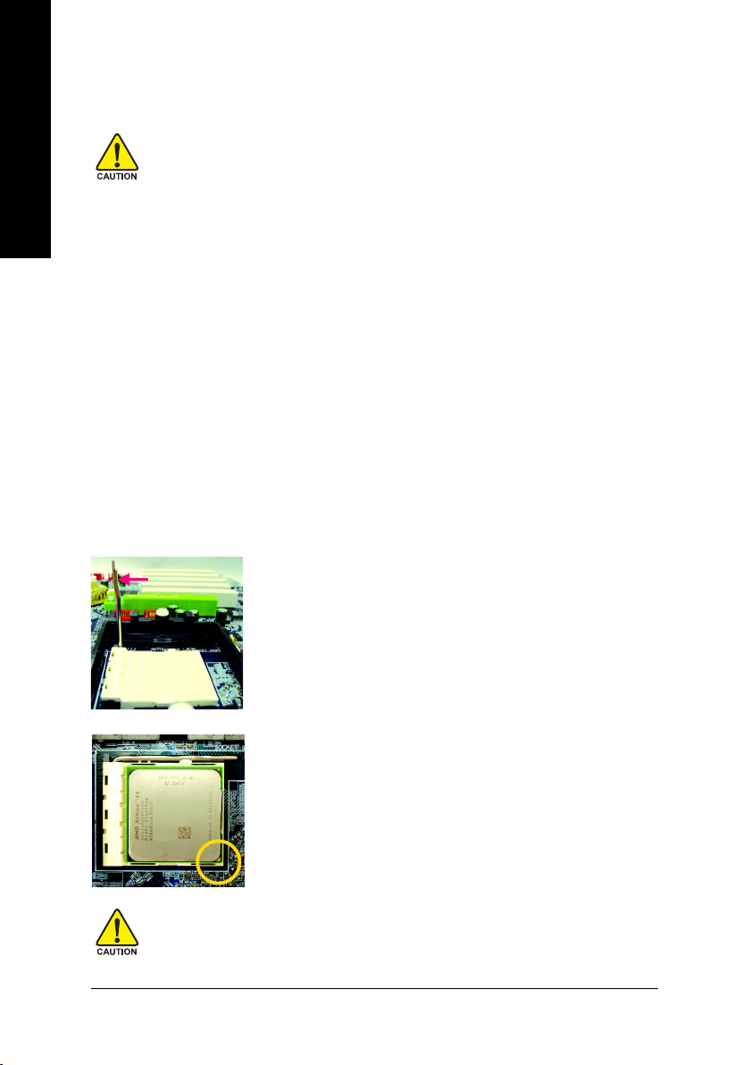
1-3-1 Installation of the CPU
Check the processor pins to see that none are bent. Move the socket lever to the unlocked position as shown
in Figure 1.(90o to the plane of the motherboard) prior to inserting the processor. The pin 1 location is
designated on the processor by a copper triangle that matches up to a triangle on the socket as shown in
Figure 2. Align the processor to the socket and gently lower it into place. Do not force the processor into the
socket.
Socket lever
Fig.1
Position lever at a 90 degree angle.
Fig.2
Pin 1 location on the socket and processor.
Gently place the CPU into position making sure that the CPU pins fit
perfectly into their holes. Once the CPU is positioned into its socket,
place one finger down on the middle of the CPU and gently press the
metal lever back into its original position.
Please use extra care when installing the CPU. The CPU will not fit if positioned incorrectly.
Rather than applying force, please change the positioning of the CPU.
K8 nForce4 SLI Series Motherboard
— 14 —
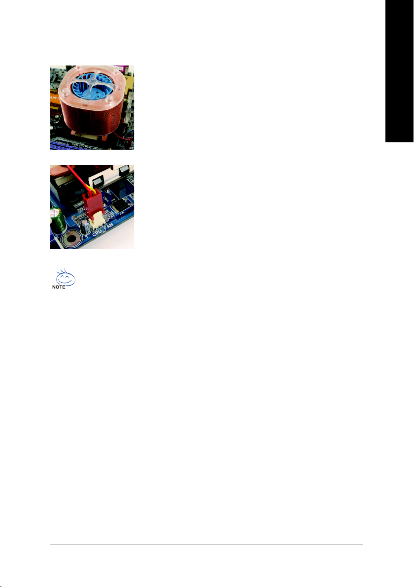
1-3-2 Installation of the Fan Heat Sink
Fig.1
Before installing the CPU fan heat sink, please first add an even layer of
heat sink paste on the surface of the CPU. Install all the fan heat sink
components (Please refer to the fan heat sink manual for detailed installation instructions).
Fig.2
Please connect the fan heat sink power connector to the CPU_FAN
connector located on the motherboard so that the fan heat sink can
properly function to prevent CPU overheating.
The fan heat sink may adhere to the CPU as a result of hardening of the heat sink paste. To
prevent such an occurrence, it is suggested that either thermal tape rather than heat sink paste
be used for heat dissipation or using extreme care when removing the fan heat sink.
English
Hardware Installation— 15 —
English
1-4 Installation of Memory
Before installing the memory modules, please comply with the following conditions:
1. Please make sure that the memory used is supported by the motherboard. It is
recommended that memory of similar capacity, specifications and brand be used.
2. Before installing or removing memory modules, please make sure that the computer power
is switched off to prevent hardware damage.
3. Memory modules have a foolproof insertion design. A memory module can be installed in
only one direction. If you are unable to insert the module, please switch the direction.
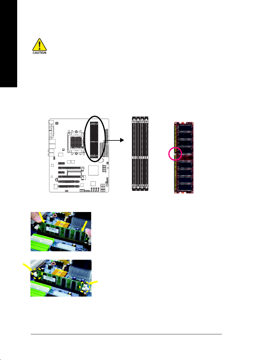
The motherboard supports DDR memory modules, whereby BIOS will automatically detect memory
capacity and specifications. Memory modules are designed so that they can be inserted only in one direction.
The memory capacity used can differ with each slot.
Notch
DDR
K8 nForce4 SLI Series Motherboard
Fig.1
The DIMM socket has a notch, so the DIMM memory module can only
fit in one direction. Insert the DIMM memory module vertically into the
DIMM socket. Then push it down.
Fig.2
Close the plastic clip at both edges of the DIMM sockets to lock the
DIMM module.
Reverse the installation steps when you wish to remove the DIMM
module.
— 16 —
Dual Channel Memory Configuration
The GA-K8N Ultra-SLI/GA-K8N Pro-SLI/GA-K8N-SLI supports the Dual Channel Technology. When the
Dual Channel Technology is activated, the bandwidth of memory bus will be double the original one.
Due to CPU limitation, if you want to operate the Dual Channel Technology, please follow the guidelines
below for Dual Channel memory configuration.
1. Dual Channel mode will not be enabled if only one DDR memory module is installed.
2. To enable Dual Channel mode with 2 memory modules (it is recommended to use memory
modules of identical brand, size, chips, and speed), you must install them into DIMM sockets
of the same color.
3. To enable Dual Channel mode with 4 memory modules, it is recommended to use memory
modules of identical brand, size, chips, and speed.
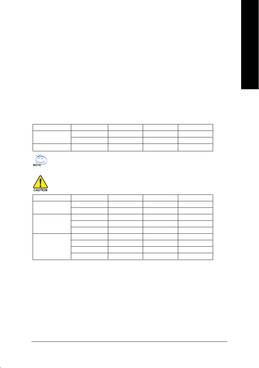
The following is a Dual Channel Memory configuration table: (DS: Double Side, SS: Single Side)
DDR 1 DDR 2 DDR 3 DDR 4
2 memory modules
4 memory modules
If two memory modules are to be used to achieve Dual Channel mode, we recommend
installing them in DDR1 and DDR2 DIMM sockets.
All of the memory configurations below will cause system unable to boot.
(DS: Double Side, SS: Single Side)
1 memory module
2 memory modules
3 memory modules
DS/SS DS/SS X X
X X DS/SS DS/SS
DS/SS DS/SS DS/SS DS/SS
DDR 1 DDR 2 DDR 3 DDR 4
X DS/SS X X
X X X DS/SS
X DS/SS DS/SS X
DS/SS X X DS/SS
X DS/SS X DS/SS
DS/SS DS/SS DS/SS X
X DS/SS DS/SS DS/SS
DS/SS X DS/SS DS/SS
DS/SS DS/SS X DS/SS
English
Hardware Installation— 17 —
English
1-5 Installation of Expansion Cards
You can install your expansion card by following the steps outlined below:
1. Read the related expansion card’s instruction document before install the expansion card into the
computer.
2. Remove your computer’s chassis cover, screws and slot bracket from the computer.
3. Press the expansion card firmly into expansion slot in motherboard.
4. Be sure the metal contacts on the card are indeed seated in the slot.
5. Replace the screw to secure the slot bracket of the expansion card.
6. Replace your computer’s chassis cover.
7. Power on the computer, if necessary, setup BIOS utility of expansion card from BIOS.
8. Install related driver from the operating system.
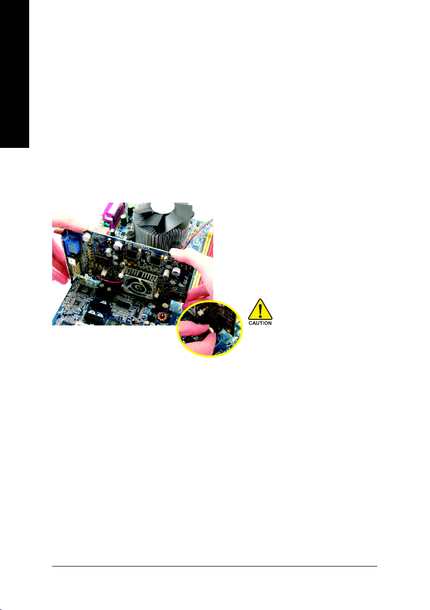
Installing a PCI Express x 16 expansion card:
Please carefully pull out the small whitedrawable bar at the end of the PCI Express
x 16 slot when you try to install/uninstall the
VGA card. Please align the VGA card to the
onboard PCI Express x 16 slot and press
firmly down on the slot. Make sure your VGA
card is locked by the small white-drawable
bar.
K8 nForce4 SLI Series Motherboard
— 18 —
1-6 Setup of SLI (Scalable Link Interface) Configuration
NVIDIA nForce4 SLI offers blistering graphics performance with the ability to bridge two NVIDIA SLIready PCI ExpressTM graphics cards! The SLI design takes advantage of the increased bandwidth of
the PCI ExpressTM bus architecture, features hardware and software innovations within NVIDIA GPU
(graphics processing unit) and the NVIDIA nForce4 chipset. Together, the NVIDIA SLI technologies work
seamlessly to allow two graphics cards to operate in parallel and share the work and deliver heartpounding PC performance. This section introduces steps to configure an SLI system on the GA-K8N
Ulra-SLI/GA-K8N Pro-SLI/GA-K8N-SLI motherboard.
Before You Begin—
I. Understanding the GIGABYTE SLI switch module:
You can find an SLI switch module socket inserted with an SLI switch
module between the first and second PCIE x 16 slots. The SLI switch
module has gold edge connectors on the top and bottom of it. One connector is SLI Mode and the other is Normal Mode.
Normal Mode: Only the first PCIE x 16 slot is available and can operate at up to x 16 in Normal Mode.
SLI Mode: In SLI Mode, the two PCIE x 16 slots can run in two modes. You can either use them as two
individual x 8 slots or install two SLI-ready PCIE x 16 cards (Example: GIGABYTE GV-NX66T128D)
of the same model and link them together with an SLI bridge connector to enable SLI function to provide
enhanced performance.
To change to a mode, you need to insert the swtich module into the switch socket with the gold edge
connector on the top. As not all PCIE slots are available while in SLI or Normal Mode, please refer to
the table below to check PCIE slots available in SLI or Normal Mode before installation.
PCIE_1 PCIE_16_1 PCIE_2 PCIE_16_2
SLI Mode
Normal Mode
«*» can run at up to PCIE x 8 mode.
Available Available* Not available Available*
Available Available Available Not available
1. Installing a device to a PCIE slot when it’s not available might damage the system.
2. We do not recommend removing the SLI switch module from the motherboard because
in that case, all PCIE slots will not be available except for the PCIE_16_1 slot, and the slot
can be used only as a PCIE x 8 slot.
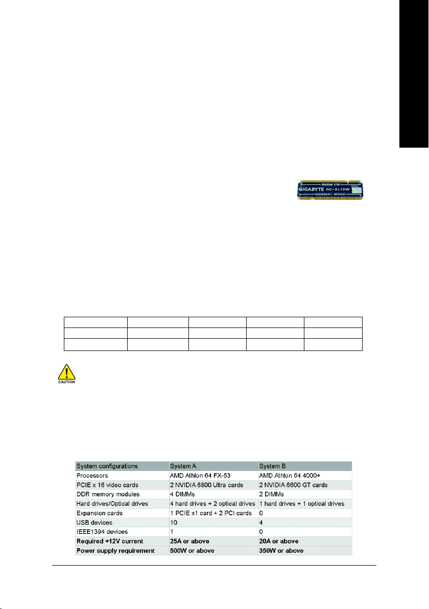
II. Power Requirements:
The exact power requirements will depend on your overall system configurations. You need a power
supply that can provide sufficient and stable power to your system and the two SLI graphics cards.
Please refer to the table below to check recommended power for different systems.
SLI Mode
Normal Mode
English
Hardware Installation— 19 —
III. Supported Operating Systems:
Only Windows XP operating system is currrently supported by the NVIDIA SLI technology.
English
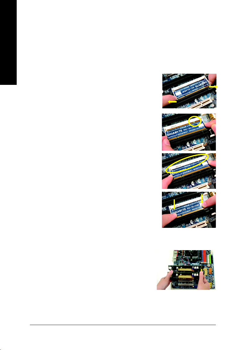
Enabling SLI Mode—
Follow the steps below to enable SLI Mode. Note that as the switch module is inserted in the socket in the
Normal Mode direction by factory default, the first step to enable SLI mode on your system is to take out the
module from the socket and insert it in the SLI Mode direction.
Step 1: Gently spread the retaining clips of the socket and the
module may then be removed from the socket. Hold the
module by the edges and lift it away from the socket.
Step 2: Position the SLI Mode side of the module above the socket at
a 25o angle. Align the small notch at the top edge of the module
with the key in the socket.
Step 3: Insert the top edge of the module into the socket. Make sure
the gold edge connectors are fully inserted.
Step 4: Gently press down on the two ends of the module until it is
locked in place by the socket clips. (You should hear a «click»
when the module is attached.)
Connecting Two Graphics Cards:
Step 1: Observe the steps in «1-5 Installation of Expansion Cards» on
page 16 and install two SLI-ready graphics cards of the same
model to the PCIE_16_1 and PCIE_16_2 slots.
K8 nForce4 SLI Series Motherboard
— 20 —
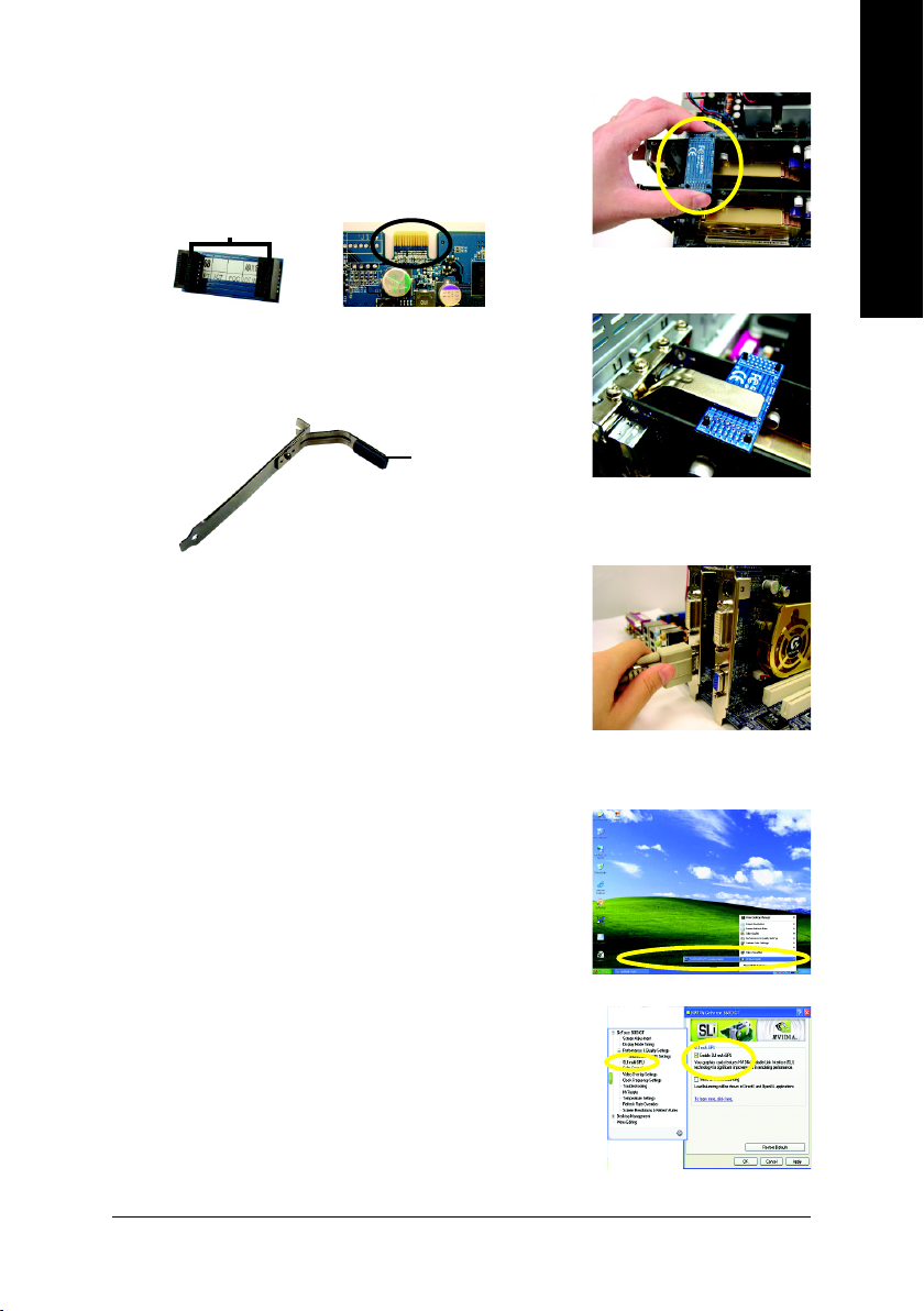
Step 2: Insert the SLI bridge (the GC-SLICON) to the SLI gold
edge connector on top of both cards. Make sure the
two mini female slots on the bridge connector securely fit onto the SLI gold edge connetors of both
cards.
Female slots on the bridge connector
Gold edge connector on the top of
graphics card
Step 3: In order to securely fix the bridge connector be-
tween the two cards, you must install the retention
bracket included with the motherboard and secure
the retention bracket to the chassis back panel with
a screw.
place this part on the top of
the bridge connector.
retention bracket
Step 4: Plug the display cable into either one of the two
graphics cards for display output. If you plug the
display cable to the card on the PCIE_16_1 slot,
make sure to set Init Display First in BIOS
Setup to PEG; if you plug the display cable to
the card on the PCIE_16_2 slot, set Init Display
First to PEG(Slot2).
English
Graphics Card Driver Setting:
Step 1: After installing graphics card driver in operating
system, right-click the NVIDIA icon in your system tray and then select NVIDIA Display. The
NVIDIA control panel will appear.
Step 2: Select SLI multi-GPU from the side menu and
then select the Enable SLI multi-GPU checkbox
in the SLI multi-GPU dialog box. System will
restart after you click Apply. Then the SLI
configuration is completed.
Hardware Installation— 21 —
English
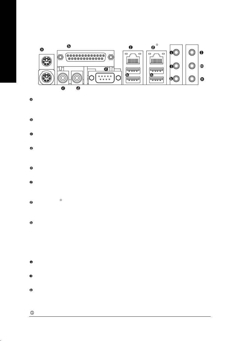
1-7 I/O Back Panel Introduction
PS/2 Keyboard and PS/2 Mouse Connector
To install a PS/2 port keyboard and mouse, plug the mouse to the upper port (green) and the keyboard to the
lower port (purple).
Parallel Port
The parallel port allows connection of a printer, scanner and other peripheral devices.
SPDIF_I (SPDIF In)
Use SPDIF In feature only when your device has digital output function.
SPDIF_O (SPDIF Out)
The SPDIF output is capable of providing digital audio to external speakers or compressed AC3
data to an external Dolby Digital Decoder.
COMA (Serial Port)
Connects to serial-based mouse or data processing devices.
LAN Port 2
The provided Internet connection is Gigabit Ethernet, providing data transfer speeds of 10/100/
1000Mbps.
LAN Port 1
The provided Internet connection is Gigabit Ethernet (PCI Express Gigabit), providing data transfer
speeds of 10/100/1000Mbps.
USB port
Before you connect your device(s) into USB connector(s), please make sure your device(s) such as
USB keyboard, mouse, scanner, zip, speaker…etc. have a standard USB interface. Also make sure
your OS supports USB controller. If your OS does not support USB controller, please contact OS
vendor for possible patch or driver upgrade. For more information please contact your OS or
device(s) vendors.
Line In
Devices like CD-ROM, walkman etc. can be connected to Line In jack.
Line Out (Front Speaker Out)
Connect the stereo speakers, earphone or front surround speakers to this connector.
MIC In
Microphone can be connected to MIC In jack.
Only for GA-K8N Ultra-SLI.
K8 nForce4 SLI Series Motherboard
— 22 —
Center/Subwoofer Speaker Out
Connect the Center/Subwoofer speakers to this connector.
Rear Speaker Out
Connect the rear surround speakers to this connector.
Side Speaker Out
Connect the side surround speakers to this connector.
You can use audio software to configure 2-/4-/6-/8-channel audio functioning.
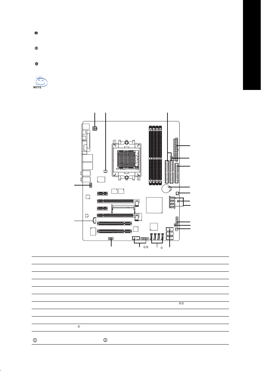
1-8 Connectors Introduction
English
11
13
1) ATX_12V
2) ATX (Power Connector)
3) CPU_FAN
4) SYS_FAN
5) PWR_FAN
6) NB_FAN
7) FDD
 IDE1 / IDE2
9) S_ATA0/1/2/3_SB
10) SATA0/1/2/3_SII
13
15
8
2
5
7
19
6
18
9
12
14
4
16
10
17
11) F_AUDIO
12) F_PANEL
13) CD_IN
14) PWR_LED
15) IR/CIR
16) F_USB1 / F_USB2/F_USB3
17) F1_1394/F2_1394
18) CLR_CMOS
19) BATTERY
Only for GA-K8N Ultra-SLI. Only for GA-K8N Pro-SLI.
Hardware Installation— 23 —
English
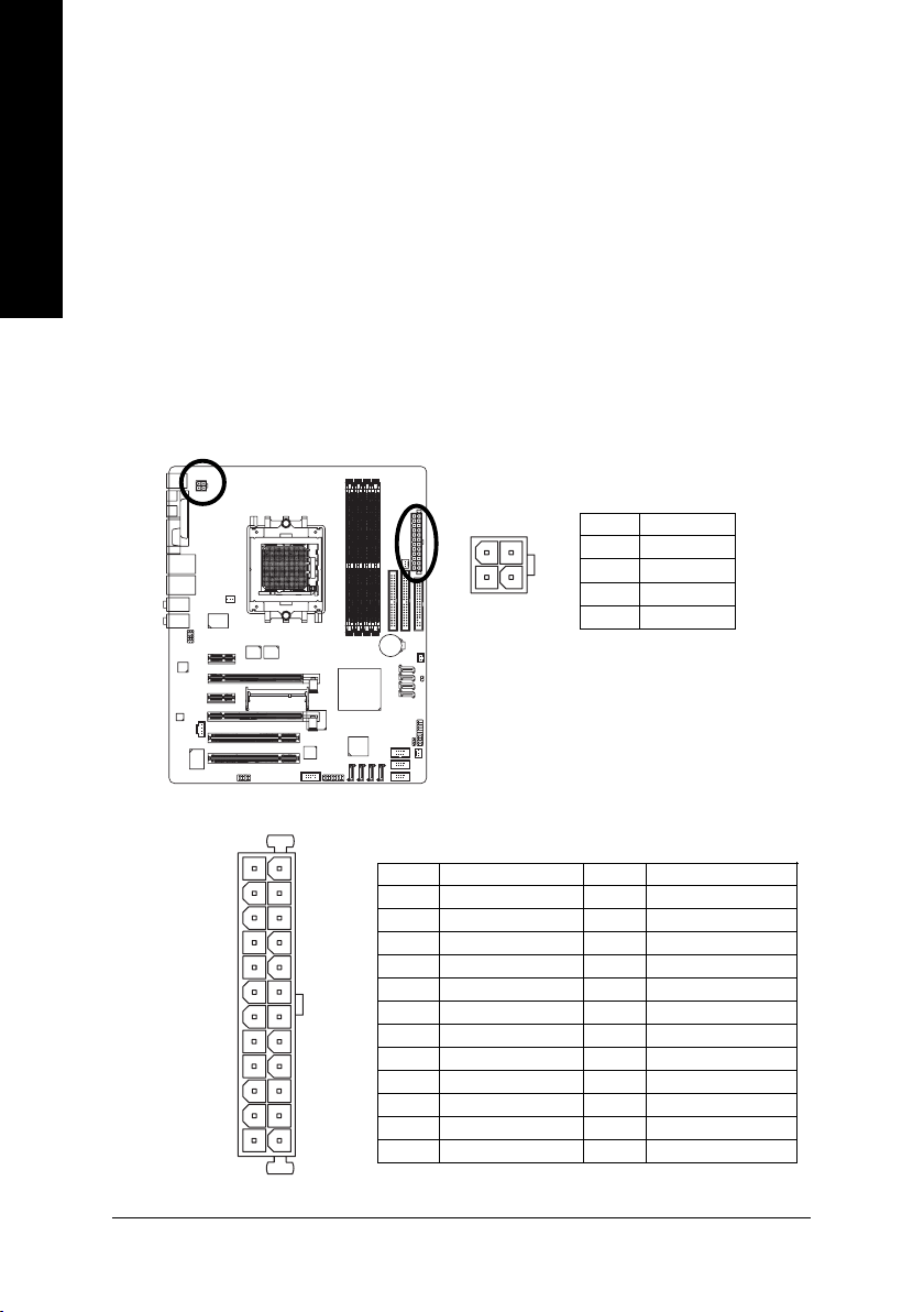
1/2) ATX_12V/ATX (Power Connector)
With the use of the power connector, the power supply can supply enough stable power to all the
components on the motherboard. Before connecting the power connector, please make sure that all
components and devices are properly installed. Align the power connector with its proper location on
the motherboard and connect tightly.
The ATX_12V power connector mainly supplies power to the CPU. If the ATX_12V power connector
is not connected, the system will not start.
Caution!
Please use a power supply that is able to handle the system voltage requirements. It is
recommended that a power supply that can withstand high power consumption be used (300W or
greater). If a power supply is used that does not provide the required power, the result can lead to an
unstable system or a system that is unable to start.
If you use a 24-pin ATX power supply, please remove the small cover on the power connector
on the motherboard before plugging in the power cord ; otherwise, please do not remove it.
Pin No. Definition
1
2
3
4
1 GND
2 GND
3 +12V
4 +12V
12
113
24
K8 nForce4 SLI Series Motherboard
Pin No. Definition
1 3.3V
2 3.3V
3 GND
4 +5V
5 GND
6 +5V
7 GND
8 Power Good
9 5V SB(stand by +5V)
10 +12V
11 +12V(Only for 24-pin ATX)
12 3.3V(Only for 24-pin ATX)
— 24 —
Pin No. Definition
13 3.3V
14 -12V
15 GND
16 PS_ON(soft On/Off)
17 GND
18 GND
19 GND
20 -5V
21 +5V
22 +5V
23 +5V (Only for 24-pin ATX)
24 GN D(Only for 24-pin ATX)
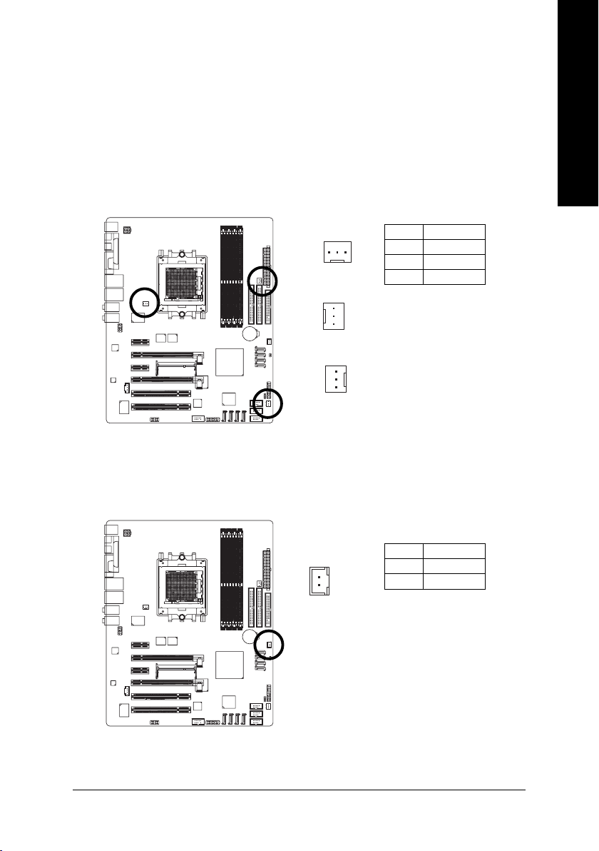
3/4/5) CPU_FAN / SYS_FAN/ PWR_FAN (Cooler Fan Power Connector)
The cooler fan power connector supplies a +12V power voltage via a 3-pin power connector and
possesses a foolproof connection design.
Most coolers are designed with color-coded power connector wires. A red power connector wire
indicates a positive connection and requires a +12V power voltage. The black connector wire is the
ground wire (GND).
Please remember to connect the power to the cooler to prevent system overheating and failure.
Caution!
Please remember to connect the power to the CPU fan to prevent CPU overheating and failure.
Pin No. Definition
1
CPU_FAN
1
SYS_FAN
1
PWR_FAN
1 GND
2 +12V
3 Sense
6) NB_FAN (Chip Fan Power Connector)
If you installed wrong direction, the chip fan will not work. Sometimes will damage the chip fan.
(Usually black cable is GND)
English
1
Pin No. Definition
1 +12V
2 GND
Hardware Installation— 25 —
English
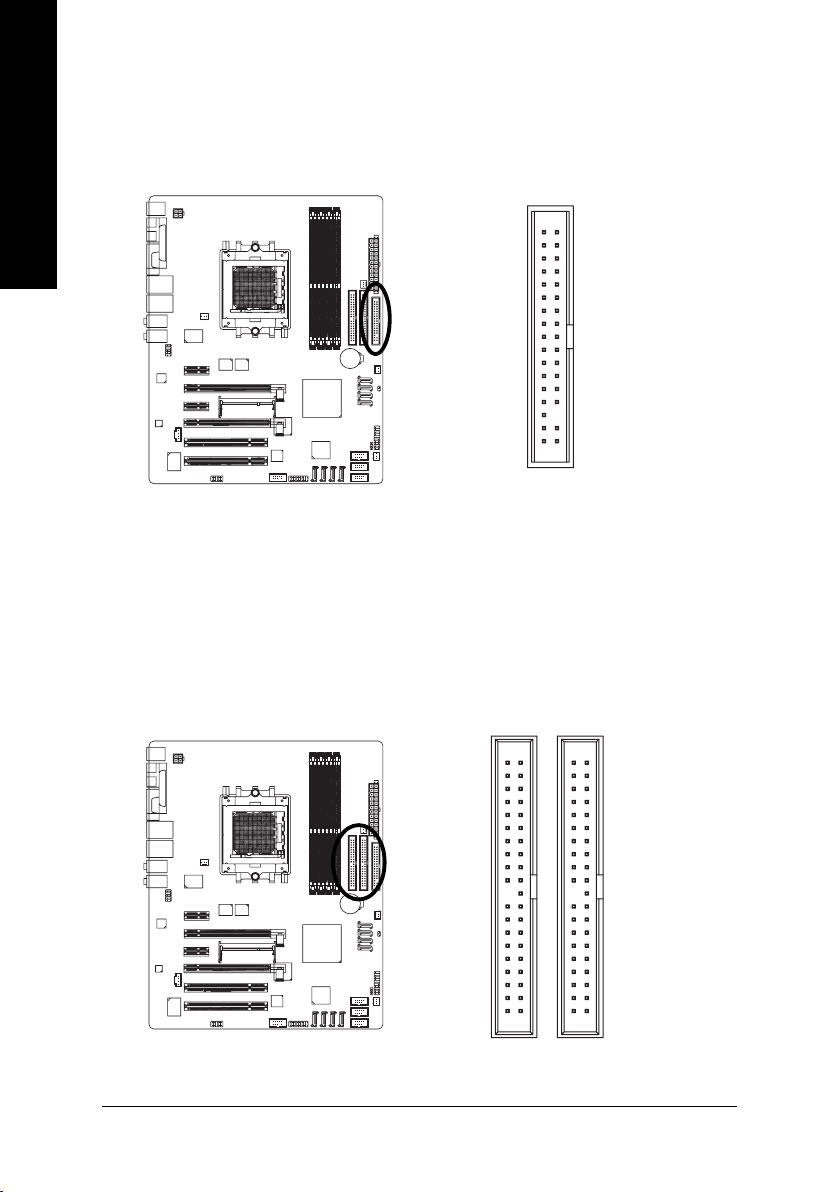
7) FDD (FDD Connector)
The FDD connector is used to connect the FDD cable while the other end of the cable connects to the
FDD drive. The types of FDD drives supported are: 360KB, 720KB, 1.2MB, 1.44MB and 2.88MB.
Please connect the red power connector wire to the pin1 position.
34
2
33
1
IDE1 / IDE2 (IDE Connector)
An IDE device connects to the computer via an IDE connector. One IDE connector can connect to one
IDE cable, and the single IDE cable can then connect to two IDE devices (hard drive or optical drive). If
you wish to connect two IDE devices, please set the jumper on one IDE device as Master and the other
as Slave (for information on settings, please refer to the instructions located on the IDE device).
40
39
K8 nForce4 SLI Series Motherboard
— 26 —
2
1
9) S_ATA0/1/2/3_SB (SATA 3Gb/s Connectors, Controlled by nForce4 SLI)
10) SATA0/1/2/3_SII (SATA Connectors, Controlled by Sil3114)
SATA 3Gb/s can provide up to 300MB/s transfer rate while SATA provides up to 150MB/s
transfer rate. Please refer to the BIOS setting for the Serial ATA controller(s)and install the proper
driver in order to work properly.
English
7
S_ATA_SB
(Controlled by nForce4 SLI)
7
1
SATA_SII
(Controlled by Sil3114)
1
Pin No. Definition
1 GND
2 TXP
3 TXN
4 GND
5RXN
6 RXP
7 GND
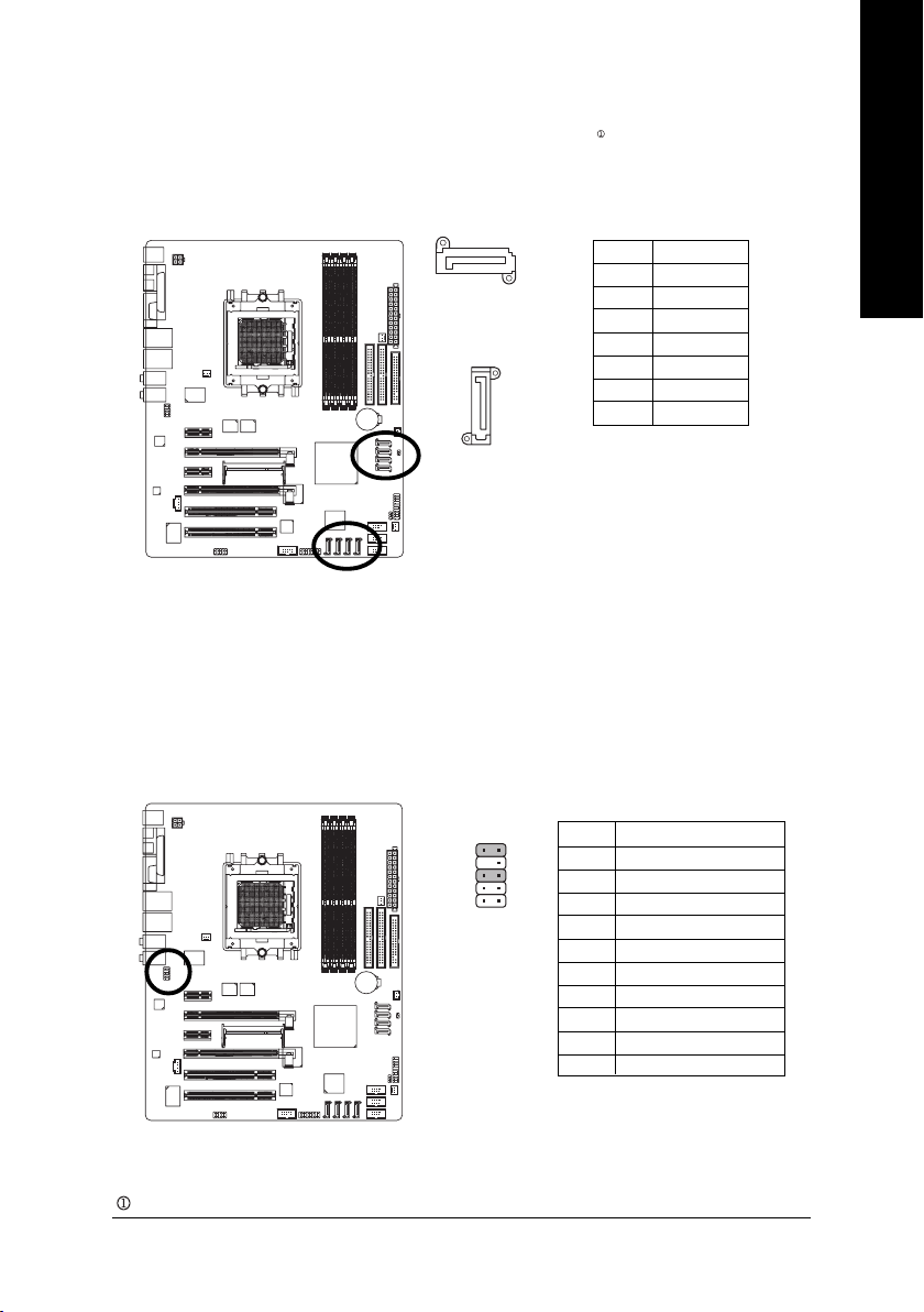
11) F_AUDIO (Front Audio Panel Connector)
If you want to use Front Audio connector, you must remove 5-6, 9-10 Jumper.
In order to utilize the front audio header, your chassis must have front audio connector. Also please
make sure the pin assigment on the cable is the same as the pin assigment on the MB header. To find
out if the chassis you are buying support front audio connector, please contact your dealer. Please note,
you can have the alternative of using front audio connector or of using rear audio connector to play
sound.
Pin No. Definition
910
12
1 MIC
2 GND
3 MIC_BIAS
4 Power
5 Front Audio (R)
6 Rear Audio (R)/ Return R
7NC
8 No Pin
9 Front Audio (L)
10 Rear Audio (L)/ Return L
Only for GA-K8N Ultra-SLI.
Hardware Installation— 27 —
Loading…
-
Страница 1
GA-K8N Ultra-SLI / GA-K8N Pro-SLI / GA-K8N-SLI AMD Socket 939 Processor Motherboard User’s Manual Rev. 1004 12ME-K8NUSLI-1004[…]
-
Страница 2
Motherboard GA-K8N Ultra-SLI Ja n. 12, 2005 Jan. 12, 2005 Motherboard GA-K8N Ultra-SLI[…]
-
Страница 3
Motherboard GA-K8N Pro-SLI Feb. 25, 2005 Feb. 25, 2005 Motherboard GA-K8N Pro-SLI[…]
-
Страница 4
Motherboard GA-K8N-SLI Aug. 8, 2005 Aug. 8, 2005 Motherboard GA-K8N-SLI[…]
-
Страница 5
Copyright © 2006 GIGA-BYTE TECHNOLOGY CO., L TD. All rights reserved. The trademarks mentioned in the manual are legally registered to their respective companies. Notice The written content provided with this product is the property of Gigabyte. No part of this manual may be reproduced, copied, translated, or transmitted in any form or by any mean[…]
-
Страница 6
— 6 — T able of Contents GA-K8N Ultra-SLI / GA-K8N Pro-SLI / GA-K8N-SLI Motherboard Layout ………………… 8 Block Diagram …………………………………………………………………………………………………. 9 Chapter 1 Hardware Installation ………………………………………………………………..[…]
-
Страница 7
— 7 — Chapter 3 Drivers Installation ………………………………………………………………………….. 55 3 — 1 Install Chipset Drivers ………………………………………………………………………… 5 5 3 -2 Software Application ……………………………………………………………………[…]
-
Страница 8
— 8 — GA-K8N Ultra-SLI / GA-K8N Pro-SLI / GA-K8N-SLI Motherboard Layout Only for GA-K8N Ultra-SLI. Only for GA-K8N Pro-SLI. ATX_12V CPU_FAN NB_FAN CODEC IT8712 nVIDIA ® nForce4 SLI Main BIOS PCI1 PCI2 F_USB2 F_USB3 VITESSE 8201 phy BATTERY ATX IDE2 FDD SYS_FAN GA-K8N Ultra-SLI or GA-K8N Pro-SLI/GA-K8N-SLI KB_MS Socket 939 AUDIO2 COMA LPT USB LAN1 […]
-
Страница 9
— 9 — Block Diagram Only for GA-K8N Ultra-SLI. Only for GA-K8N Pro-SLI. Center/Subwoofer Spear Out AMD K8 Socket 939 CPU CPUCLK+/-(200MHz) Hyper Transport Bus nVIDIA ® nForce4 SLI DDR 400/333/266/200MHz DIMM 24MHz 33MHz IT8712 4 SA T A 3Gb/s A T A33/66/100/133 IDE Channels PCICLK (33MHz) 2PCI PCI Bus Marvell 8053 RJ45 10 USB Ports Dual Channel Mem[…]
-
Страница 10
— 10 -[…]
-
Страница 11
Hardware Installation — 11 — English 1-1 Considerations Prior to Installation Preparing Y our Computer The motherboard contains numerous delicate electronic circuits and components which can become damaged as a result of electrostatic discharge (ESD). Thus, prior to installation, please follow the instructions below: 1. Please turn off the computer[…]
-
Страница 12
— 12 — English K8 nForce4 SLI Series Motherboard Motherboard GA-K8N Ultra-SLI or GA-K8N Pro-SLI or GA-K8N-SLI CPU Socket 939 for AMD Athlon TM 64 / 64 FX processor (K8) 2000MT/s system bus Supports core frequencies in excess of 3000+ and faster Chipset nVIDIA ® nForce4 SLI Chipset Memory 4 DDR DIMM memory slots (supports up[…]
-
Страница 13
Hardware Installation — 13 — English I/O Control IT8712 Hardware Monitor System voltage detection CPU temperature detection CPU / System / Power fan speed detection CPU warning temperature CPU fan failure warning CPU smart fan control Onboard SA T A RAID Onboard nForce4 SLI chipset (S_A T A0_SB, S_A TA1_SB, S_A T A2_[…]
-
Страница 14
— 14 — English K8 nForce4 SLI Series Motherboard 1 -3 Installation of the CPU and Fan Heat Sink Before installing the CPU, please comply with the following conditions: 1. Please make sure that the motherboard supports the CPU. 2. Please take note of the one indented corner of the CPU. If you install the CPU in the wrong direction, the CPU will not […]
-
Страница 15
Hardware Installation — 15 — English 1-3-2 Installation of the Fan Heat Sink The fan heat sink may adhere to the CPU as a result of hardening of the heat sink paste. T o prevent such an occurrence, it is suggested that either thermal tape rather than heat sink paste be used for heat dissipation or using extreme care when removing the fan heat sink.[…]
-
Страница 16
— 16 — English K8 nForce4 SLI Series Motherboard Before installing the memory modules, please comply with the following conditions: 1. Please make sure that the memory used is supported by the motherboard. It is recommended that memory of similar capacity, specifications and brand be used. 2. Before installing or removing memory modules, please mak[…]
-
Страница 17
Hardware Installation — 17 — English Dual Channel Memory Configuration The GA-K8N Ultra-SLI/GA-K8N Pro-SLI/GA-K8N-SLI supports the Dual Channel T echnology . When the Dual Channel T echnology is activated, the bandwidth of memory bus will be double the original one. Due to CPU limitation, if you want to operate the Dual Channel T echnology , please[…]
-
Страница 18
— 18 — English K8 nForce4 SLI Series Motherboard 1 -5 Installation of Expansion Cards Y ou can install your expansion card by following the steps outlined below: 1. Read the related expansion card’s instruction document before install the expansion card into the computer. 2. Remove your computer’s chassis cover, screws and slot bracket fr[…]
-
Страница 19
Hardware Installation — 19 — English 1 -6 Setup of SLI (Scalable Link Interface) Configuration NVIDIA nForce4 SLI offers blistering graphics performance with the ability to bridge two NVIDIA SLI- ready PCI Express TM graphics cards! The SLI design takes advantage of the increased bandwidth of the PCI Express TM bus architecture, features hardware a[…]
-
Страница 20
— 20 — English K8 nForce4 SLI Series Motherboard Connecting Two Graphics Cards: Step 1: Observe the steps in «1-5 Installation of Expansion Cards» on page 16 and install two SLI-ready graphics cards of the same model to the PCIE_16_1 and PCIE_16_2 slots. Step 2: Position the SLI Mode side of the module above the socket at a 25 o angle. Al[…]
-
Страница 21
Hardware Installation — 21 — English Graphics Card Driver Setting: Step 1: After installing graphics card driver in operating system, right-click the NVIDIA icon in your sys- tem tray and then select NVIDIA Display . The NVIDIA control panel will appear. Step 2: Select SLI multi-GPU from the side menu and then select the Enable SLI multi-GPU checkb[…]
-
Страница 22
— 22 — English K8 nForce4 SLI Series Motherboard 1 -7 I/O Back Panel Introduction PS/2 Keyboard and PS/2 Mouse Connector T o install a PS/2 port keyboard and mouse, plug the mouse to the upper port (green) and the keyboard to the lower port (purple). Parallel Port The parallel port allows connection of a printer, scanner and other peripheral device[…]
-
Страница 23
Hardware Installation — 23 — English 1 -8 Connectors Introduction Center/Subwoofer Speaker Out Connect the Center/Subwoofer speakers to this connector. Rear Speaker Out Connect the rear surround speakers to this connector. Side Speaker Out Connect the side surround speakers to this connector. Y ou can use audio software to configure 2-/4-/6-/8-chan[…]
-
Страница 24
— 24 — English K8 nForce4 SLI Series Motherboard 1/2) A TX_12V/A TX (Power Connector) With the use of the power connector, the power supply can supply enough stable power to all the components on the motherboard. Before connecting the power connector, please make sure that all components and devices are properly installed. Align the power connector[…]
-
Страница 25
Hardware Installation — 25 — English 3/4/5) CPU_F AN / SYS_F AN/ PWR_FAN (Cooler Fan Power Connector) The cooler fan power connector supplies a +12V power voltage via a 3-pin power connector and possesses a foolproof connection design. Most coolers are designed with color-coded power connector wires. A red power connector wire indicates a positive […]
-
Страница 26
— 26 — English K8 nForce4 SLI Series Motherboard 8 ) IDE1 / IDE2 (IDE Connector) An IDE device connects to the computer via an IDE connector. One IDE connector can connect to one IDE cable, and the single IDE cable can then connect to two IDE devices (hard drive or optical drive). If you wish to connect two IDE devices, please set the jumper on one[…]
-
Страница 27
Hardware Installation — 27 — English 9 ) S_A T A0/1/2/3_SB (SA T A 3Gb/s Connectors, Controlled by nForce4 SLI) 1 0 ) SA T A0/1/2/3_SII (SA T A Connectors, Controlled by Sil3114) SA T A 3Gb/s can provide up to 300MB/s transfer rate while SA T A provides up to 150MB/s transfer rate. Please refer to the BIOS setting for the Serial A T A controller(s)[…]
-
Страница 28
— 28 — English K8 nForce4 SLI Series Motherboard 1 2 ) F_PANEL (Front Panel Jumper) Please connect the power LED, PC speaker, reset switch and power switch etc of your chassis front panel to the F_P ANEL connector according to the pin assignment below . 1 2 19 20 HD- HD+ RES+ RES- NC SPEAK- MSG- MSG+ PW- PW+ SPEAK+ Message LED/ Power/ Sleep LED Pow[…]
-
Страница 29
Hardware Installation — 29 — English 1 3 ) CD_IN (CD In Connector) Connect CD-ROM or DVD-ROM audio out to the connector. Pin No. Definition 1 CD-L 2 GND 3 GND 4 CD-R 1 1 4 ) PWR_LED PWR_LED is connect with the system power indicator to indicate whether the system is on/off. It will blink when the system enters suspend mode. Pin No. Definition 1 MPD[…]
-
Страница 30
— 30 — English K8 nForce4 SLI Series Motherboard 1 5) IR_CIR Make sure the pin 1 on the IR device is align with pin one the connector . T o enable the IR/CIR function, you are required to purchase an optional IR/CIR module. T o use IR function only , please connect IR module to Pin1 to Pin5. Be careful with the polarity of the IR/CIR connector. Che[…]
-
Страница 31
Hardware Installation — 31 — English 1 7) F1_1394/F2_1394 (IEEE 1394 Connectors) Serial interface standard set by Institute of Electrical and Electronics Engineers, which has features like high speed, high bandwidth and hot plug. Be careful with the polarity of the IEEE1394 connector. Check the pin assignment carefully while you connect the IEEE139[…]
-
Страница 32
— 32 — English K8 nForce4 SLI Series Motherboard 1 9 ) BA TTERY Danger of explosion if battery is incorrectly replaced. Replace only with the same or equivalent type recommended by the manufacturer. Dispose of used batteries according to the manufacturer’s instructions. If you want to erase CMOS… 1. Turn OFF the computer and unplug the power[…]
-
Страница 33
BIOS Setup — 33 — English BIOS (Basic Input and Output System) includes a CMOS SETUP utility which allows user to configure required settings or to activate certain system features. The CMOS SETUP saves the configuration in the CMOS SRAM of the motherboard. When the power is turned off, the battery on the motherboard supplies the necessary power to[…]
-
Страница 34
K8 nForce4 SLI Series Motherboard — 3 4 — English The Main Menu (For example: BIOS V er . : F6a) Once you enter Award BIOS CMOS Setup Utility , the Main Menu (as figure below) will appear on the screen. Use arrow keys to select among the items and press <Enter> to accept or enter the sub-menu. Standard CMOS Features This s[…]
-
Страница 35
BIOS Setup — 35 — English Set Supervisor Password Change, set, or disable password. It allows you to limit access to the system and Setup, or just to Setup. Set User Password Change, set, or disable password. It allows you to limit access to the system. Save & Exit Setup Save CMOS valu[…]
-
Страница 36
K8 nForce4 SLI Series Motherboard — 3 6 — English 2-1 Standard CMOS Features Date The date format is <week>, <month>, <day>, <year>. Week The week, from Sun to Sat, determined by the BIOS and is display only Month The month, Jan. Through Dec. Day The day, from 1 to 31 (or the maximum allowed in the month) Y ear The year, fro[…]
-
Страница 37
BIOS Setup — 37 — English Cylinder Number of cylinders Head Number of heads Precomp Write precomp Landing Zone Landing zone Sector Number of sectors Drive A / Drive B The category identifies the types of floppy disk drive A or drive B that has been installed in the computer. None No floppy drive installed 360K, 5.25″ 5.25 inch PC-type standard[…]
-
Страница 38
K8 nForce4 SLI Series Motherboard — 3 8 — English 2-2 Advanced BIOS Features Hard Disk Boot Priority Select boot sequence for onboard(or add-on cards) SCSI, RAID, etc. Use < > or < > to select a device, then press<+> to move it up, or <-> to move it down the list. Press <ESC> to exit this menu. First / Second / Third B[…]
-
Страница 39
BIOS Setup — 39 — English Password Check System The system can not boot and can not access to Setup page will be denied if the correct password is not entered at the prompt. Setup The system will boot, but access to Setup will be denied if the correct password is not entered at the prompt. (Default value) Init Display First This feature allows you […]
-
Страница 40
K8 nForce4 SLI Series Motherboard — 4 0 — English 2-3 Integrated Peripherals On-Chip IDE Channel0 Enabled Enable onboard 1st channel IDE port. (Default value) Disabled Disable onboard 1st channel IDE port. On-Chip IDE Channel1 Enabled Enable onboard 2nd channel IDE port. (Default value) Disabled Disable onboard 2nd channel IDE port. IDE DMA transfe[…]
-
Страница 41
BIOS Setup — 41 — English On-Chip MAC Lan Auto Auto-detect onbo ard LAN chip function. (Default value) Disabled Disable onboard LAN chip function. On-Chip LAN BOOT ROM This function decide whether to invoke the boot ROM of the onboard LAN chip. Enabled Enable this function. (Default value) Disabled Disable this function. NV IDE/SA T A RAID function[…]
-
Страница 42
K8 nForce4 SLI Series Motherboard — 4 2 — English NV SA T A 2 class code (Note) 0101 Set NV SA T A 2 class code to 0101. (Default value) 0104 Set NV SA T A 2 class code to 0104. NV SA T A 2 Primary RAID Enabled Enable 2nd SA T A primary RAID function. (Default value) Disabled Disable this function. NV SA T A 2 Secondary RAID Enabled Enable 2nd SA T[…]
-
Страница 43
BIOS Setup — 43 — English Onboard Serial Port 1 Auto BIOS will automatically setup the Serial port 1 address. 3F8/IRQ4 Enable onboard Serial port 1 and address is 3F8/IRQ4. (Default value) 2F8/IRQ3 Enable onboard Serial port 1 and address is 2F8/IRQ3. 3E8/IRQ4 Enable onboard Serial port 1 and address is 3E8/IRQ4. 2E8/IRQ3 Enable onboard Serial port[…]
-
Страница 44
K8 nForce4 SLI Series Motherboard — 4 4 — English 2 -4 Power Management Setup ACPI Suspend T ype S1(POS) Set ACPI suspend type to S1/POS(Power On Suspend). (Default value) S3(STR) Set ACPI suspend type to S3/STR(Suspend T o RAM). Soft-Off by Power button Instant-off Press power button then Power off instantly . (Default value) Delay 4 Sec Press pow[…]
-
Страница 45
BIOS Setup — 45 — English Day of Month Alarm : Everyday, 1~31 Time (hh: mm: ss) Alarm : (0~23) : (0~59) : (0~59) Power On By Mouse Disabled Disable this function. (Default value) Double Click Double click on PS/2 mouse left button to power on the system. Power On By Keyboard Disabled Disable this function. (Default value) Password Enter from 1 to 5[…]
-
Страница 46
K8 nForce4 SLI Series Motherboard — 4 6 — English 2-6 PC Health Status CMOS Setup Utility-Copyright (C) 1984-2005 A ward Software PC Health Status Vcore OK DDR25V OK +3.3V OK +12V OK Current CPU T e mperature 34 o C Current CPU F A N Speed 3183 RPM Current POWER F A N Speed 0 RPM Current SYSTEM F AN Speed 0 RPM CPU W arning T emperature [Disabled] […]
-
Страница 47
BIOS Setup — 47 — English Current V oltage(V) Vcore / DDR25V / +3.3V / +12V Detect system’s voltage status automatically. Current CPU T emperature Detect CPU temperature automatically. Current CPU/POWER/SYSTEM F AN Speed (RPM) Detect CPU/Power/System fan speed status automatically. CPU W arning T emperature 60 o C / 140 o F Monitor CPU tempera[…]
-
Страница 48
K8 nForce4 SLI Series Motherboard — 4 8 — English T emp of F AN turn off (Default temperature: 0 o C) When the CPU temperature is below the value set in this option, the CPU fan will stop spinning. T emp Limit of Low Speed (Default temperature: 20 o C) The CPU fan will stop spinning when the CPU temperature is below the value set in Temp of FAN tur[…]
-
Страница 49
BIOS Setup — 49 — English 2 -7 MB Intelligent T weaker(M.I.T .) Incorrect using these features may cause your system broken. For power end-user use only. CMOS Setup Utility-Copyright (C) 1984-2005 Award Software MB Intelligent T weaker(M.I.T .) HT Frequency ratio [Auto] CPU Frequency [200] K8 CPU Clock Ratio [Auto] Current DDR speed 266 DDR Clock/ […]
-
Страница 50
K8 nForce4 SLI Series Motherboard — 5 0 — English Current DDR Speed Displays the current DDR speed. DDR clock/Timing Mode Auto Set DDR Clock and Timing Mode automatically. (Default value) Manual Set DDR Clock and Timing Mode manually. CPU/DDR clock Ratio Set the CPU/DDR clock ratio. Options include 2/1, 2/1.33, 2/1.5, 2/1.66, 2/1.83, 2/2. DDR Speed[…]
-
Страница 51
BIOS Setup — 51 — English Refresh Rate (Tref) Set the Refresh Rate. Read Preamble value 2~9.5ns Set the Read Preamble value. (Default value: 7ns) Async Latency value 2~9ns Set the Async Latency value (Default value: 7ns) CPU Spread Spectrum Disabled Disable CPU Spread Spectrum. Center Spread Set CPU Spread Spectrum to Center Spread. (Default value)[…]
-
Страница 52
K8 nForce4 SLI Series Motherboard — 5 2 — English 2 -8 T op Performance If you wish to maximize the performance of your system, enable «T op Performance.» Disabled Disable this function. (Default V alue) Enabled Enable T op Performance function. «T op Performance» will increase H/W working speed. Different system configuration ([…]
-
Страница 53
BIOS Setup — 53 — English 2-10 Set Supervisor/User Password When you select this function, the following message will appear at the center of the screen to assist you in creating a password. T ype the password, up to eight characters, and press <Enter>. Y ou will be asked to confirm the password. Type the password again and press <Enter>[…]
-
Страница 54
K8 nForce4 SLI Series Motherboard — 5 4 — English 2 -1 1 Save & Exit Setup Type «Y» will quit the Setup Utility and save the user setup value to RTC CMOS. Type «N» will return to Setup Utility. 2-12 Exit Without Saving Type «Y» will quit the Setup Utility without saving to RTC CMOS. Type «N» will return t[…]
-
Страница 55
Drivers Installation — 55 — English Pictures below are shown in Windows XP. Insert the driver CD-title that came with your motherboard into your CD-ROM drive, the driver CD-title will auto start and show the installation guide. If not, please double click the CD-ROM device icon in «My computer», and execute the Setup.exe. Chapter 3 Driver[…]
-
Страница 56
K8 nForce4 SLI Series Motherboard — 5 6 — English 3-2 Software Application This page displays all the tools that Gigabyte developed and some free software, you can choose anyone you want and press «install» to install them. 3-3 Software Information This page lists the contents of software and drivers in this CD-title. 1 1 1 1 1 Only for G[…]
-
Страница 57
Drivers Installation — 57 — English 3-4 Hardware Information This page lists all device you have for this motherboard. 3-5 Contact Us Please see the last page for details.[…]
-
Страница 58
K8 nForce4 SLI Series Motherboard — 5 8 — English[…]
-
Страница 59
Appendix — 59 — English 4-1-1 EasyT une 5 Introduction EasyTune 5 presents the most convenient Windows based system performance enhancement and manageability utility. Featuring several powerful yet easy to use tools such as 1) Overclocking for enhancing system performance, 2) C.I.A. and M.I.B. for special enhancement for CPU and Memory, 3) Smart-Fa[…]
-
Страница 60
K8 nForce4 SLI Series Motherboard — 6 0 — English 4-1-2 Xpress Recovery2 Introduction Xpress Recovery2 is designed to provide quick backup and restora- tion of hard disk data. Supporting Microsoft operating systems including Windows XP/2000/NT/98/Me and DOS, and file systems including F A T16, FA T32, and NTFS, Xpress Recovery2 is able to back up d[…]
-
Страница 61
Appendix — 61 — English 1. RESTORE: Restore the backed-up data to your hard disk. (This button will not appear if there is no backup file.) 2. BACKUP: Back up data from hard disk. 3. REMOVE: Remove previously-created backup files to release disk space. (This button will not appear if there is no backup file.) 4. REBOOT: Exit the main screen and res[…]
-
Страница 62
K8 nForce4 SLI Series Motherboard — 6 2 — English 4-1-3 Flash BIOS Method Introduction A. What is Dual BIOS T echnology? Dual BIOS means that there are two system BIOS (ROM) on the motherboard, one is the Main BIOS and the other is Backup BIOS. b . Dual BIOS / Q-Flash Programming Utility B. How to use Dual BIOS and Q-Flash Utility? a. After power o[…]
-
Страница 63
Appendix — 63 — English c . Dual BIOS Item explanation: Wide Range Protection: Disable(Default), Enable Status 1: If any failure (ex. Update ESCD failure, checksum error or reset? occurs in the Main BIOS, just before the Operating System is loaded and after the power is on, and that the Wide Range Protection is set to «Enable», the PC wil[…]
-
Страница 64
K8 nForce4 SLI Series Motherboard — 6 4 — English Method 1 : Q-Flash TM Utility Q-Flash TM is a BIOS flash utility embedded in Flash ROM. With this utility, users only have to stay in the BIOS menu when they want to update BIOS. Q-Flash TM allows users to flash BIOS without any utility in DOS or Windows. Using Q-Flash TM indicating no more fooling […]
-
Страница 65
Appendix — 65 — English Entering the Q-Flash TM utility: CMOS Setup Utility-Copyright (C) 1984-2004 A ward Software Standard CMOS Feature s Adva nced BIOS Features Integrated Peripherals Power M anage ment Setup PnP/PCI Configurations PC Health Status MB Intelligent Tweaker(M.I.T .) Select La nguage Loa d Fail-Safe Defau[…]
-
Страница 66
K8 nForce4 SLI Series Motherboard — 6 6 — English Dual BIOS Utility Boot From………………………………….. M ain Bios Main ROM T ype/Size………………………..SST 49LF003A 512K Backup ROM T ype/Size…………………….SST 49LF003A 512K Wide Ra nge Protection Disable Boot From M ain Bios Auto Recovery Enab le Halt On Error Di[…]
-
Страница 67
Appendix — 67 — English 3. Press Y button on your keyboard after you are sure to update BIOS. Then it will begin to update BIOS. The progress of updating BIOS will be displayed. Dual BIOS Utility Boot From………………………………….. M ain Bios Main ROM T ype/Size………………………..SST 49LF003A 512K Backup ROM T ype/Size…..[…]
-
Страница 68
K8 nForce4 SLI Series Motherboard — 6 8 — English CMOS Setup Utility-Copyright (C) 1984-2004 A ward Software Standard CMOS Feature s Adva nced BIOS Features Integrated Peripherals Power M anage ment Setup PnP/PCI Configurations PC Health Status MB Intelligent Tweaker(M.I.T .) ESC: Quit F3: Cha nge La nguage F8: Dual BIOS[…]
-
Страница 69
Appendix — 69 — English Exploring the Q-Flash TM utility screen The Q-FlashBIOS utility screen consists of the following key components. T ask menu for Q-Flash utility: Contains the names of three tasks. Blocking a task and pressing Enter key on your keyboard to enable execution of the task. Action bar: Contains the names of four actions needed to […]
-
Страница 70
K8 nForce4 SLI Series Motherboard — 7 0 — English 3. Press Y button on your keyboard after you are sure to update BIOS. Then it will begin to update BIOS. The progress of updating BIOS will be shown at the same time. Q-Flash Utility V1.30 Flash T ype/Size……………………………SST 49LF003A 256K Keep DMI Data Ena ble Update BIOS from Flopp[…]
-
Страница 71
Appendix — 71 — English Method 2 : @BIOS TM Utility If you do not have a DOS startup disk, we recommend that you use the new @BIOS utility. @BIOS allows users to update their BIOS under Windows. Just select the desired @BIOS server to download the latest version of BIOS. 1. Methods and steps: I. Update BIOS through Internet: a. Click «Internet[…]
-
Страница 72
K8 nForce4 SLI Series Motherboard — 7 2 — English III. Save BIOS: In the very beginning, there is «Save Current BIOS» icon shown in dialog box. It means to save the current BIOS version. IV. Check out supported motherboard and Flash ROM: In the very beginning, there is «About this program» icon shown in dialog box. It can help y[…]
-
Страница 73
Appendix — 73 — English 4-1-4 Serial A T A BIOS Setting Utility Introduction RAID Levels RAID (Redundant Array of Independent Disks) is a method of combining two hard disk drives into one logical unit. The advantage of an Array is to provide better performance or data fault tolerance. Fault tolerance is achieved through data redundant operation, wh[…]
-
Страница 74
K8 nForce4 SLI Series Motherboard — 7 4 — English Please follow the steps below to construct a complete RAID array: 1) Have ready your hard drives for RAID construction. Note: T o achieve best performance, it is recommended that the hard drives used are of similar make and storage capacity. 2) Please attach the hard drive connectors to their approp[…]
-
Страница 75
Appendix — 75 — English Using the «Define a New Array» Window If necessary, press the tab key to move from field to field until the appropriate field is highlighted. Selecting the RAID Mode By default, this is set to Mirroring. T o change to a different RAID mode, press the down arrow key until the mode that you want appears in the RAID M[…]
-
Страница 76
K8 nForce4 SLI Series Motherboard — 7 6 — English Completing the RAID BIOS Setup After assigning your RAID array disks, press F7. The Clear disk data prompt appears. N VIDIA RAID Utility Nov 5 10 2004 — Define a New Array — RAID Mode: Mirr oring Striping Block: Opti m al Free Disks Loc Disk Model Na me Array Disks Loc Disk Model Na me [ […]
-
Страница 77
Appendix — 77 — English Press Enter to view and verify details. The Array Detail screen appears. The Array Detail screen shows various information about the array that you selected, such as Striping Block used, RAID Mode, Striping Width, Disk Model Name, and disk capacity. Array 2 : N VIDIA MIRROR 1 11.79G — Array Detail — RAID Mode: M irr oring St[…]
-
Страница 78
K8 nForce4 SLI Series Motherboard — 7 8 — English Installing the RAID drivers T o install operating system onto a serial A T A hard disk successfully, you need to install the SA T A controller driver during OS installation. Without the driver, the hard disk may not be recognized during the Windows setup process. First of all, copy the driver for th[…]
-
Страница 79
Appendix — 79 — English 4-1-5 2- / 4- / 6- / 8- Channel Audio Function Introduction Line Out Stereo Speakers Connection and Settings: We recommend that you use the speaker with amplifier to acquire the best sound effect if the stereo output is applied. STEP 1: Connect the stereo speakers or earphone to «Line Out». STEP 2 : Following insta[…]
-
Страница 80
K8 nForce4 SLI Series Motherboard — 8 0 — English STEP 3: Click «Speaker Configuration» then click on the left selection bar and select «2CH Speaker» to complete 2 channel audio configuration. 4 Channel Audio Setup STEP 1 : Connect the front channels to «Front Speaker Out», the rear channels to «Rear Speaker Out&q[…]
-
Страница 81
Appendix — 81 — English 6 Channel Audio Setup STEP 1 : Connect the front channels to «Front Speaker Out», the rear channels to «Rear Speaker Out», and the Center/Subwoofer channels to «Center/Subwoofer Speaker Out». STEP 2 : Following installation of the audio driver, you find a Sound Effect icon on the lower right han[…]
-
Страница 82
K8 nForce4 SLI Series Motherboard — 8 2 — English 8 Channel Audio Setup STEP 1 : Connect the front channels to «Front Speaker Out», the rear channels to «Rear Speaker Out», the Cen- ter/Subwoofer channels to «Center/Subwoofer Speaker Out», and the side channels to «Side Speaker Out». STEP 2 : Following instal[…]
-
Страница 83
Appendix — 83 — English Jack-Sensing Introduction Jack-Sensing provides audio connectors error-detection function. Install Microsoft DirectX8.1 or later version before to enable Jack-Sensing support for Windows 98/ 98SE/ 2000/ ME. Jack-Sensing includes 2 parts: AUTO and MANUAL. Following is an example for 2 channels (Following pictures are in Windo[…]
-
Страница 84
K8 nForce4 SLI Series Motherboard — 8 4 — English If you set wrong with the connectors, the warning message will come out as right picture. Manual setting: If the device picture shows different from what you set, please press «Manual Selection» to set.[…]
-
Страница 85
Appendix — 85 — English 4-2 T roubleshooting Below is a collection of general asked questions. T o check general asked questions based on a specific motherboard model, please log on to www.gigabyte.com.tw Question 1: I cannot see some options that were included in previous BIOS after updating BIOS. Why? Answer: Some advanced options are hidden in n[…]
-
Страница 86
K8 nForce4 SLI Series Motherboard — 8 6 — English[…]
-
Страница 87
Appendix — 87 — English Contact Us T aiwan (Headquarters) GIGA-BYTE TECHNOLOGY CO., L TD. Address: No.6, Bau Chiang Road, Hsin-Tien, T aipei 231, T aiwan TEL: +886-2-8912-4888 FAX: +886-2-8912-4003 T ech. Support : http://tw.giga-byte.com/T echSupport/ServiceCenter .htm Non-T ech. Support(Sales/Marketing) : http://ggts.gigabyte.[…]
-
Страница 88
K8 nForce4 SLI Series Motherboard — 8 8 — English China NINGBO G.B.T . TECH. TRADING CO., L TD. T ech. Support : http://tw.giga-byte.com/T echSupport/ServiceCenter .htm Non-T ech. Support(Sales/Marketing) : http://ggts.gigabyte.com.tw/nontech.asp WEB address : http://www.gigabyte.com.cn Shanghai TEL: +86-021-63410999 FAX: +86-02[…]