
В виде стереомикроскопа SM XX Вы приобрели один из благонадежных и испытанных во многих областях науки и техники стереомикроскоп. Теперь оптимальное использование возможностей микроскопа лежит в Ваших руках. Настоящая инструкция должна Вам помочь при этом по лучшим силам. Причиной большой популярности стереомикроскопа SM XX является его оптическая конструкция, которая при общем диапазоне увеличения 4Х . . . 100Х при полях зрения диаметром 44 … 2 мм обеспечивает не изменяющееся рабочее расстояние 100 мм.
Рукоятка для быстрой смены кратности увеличения в виде барабана, позволяющая переключение на увеличения 0,63; 1,0; 1,6; 2,5; 4,0; т. е. общий фактор 6,3; особенно бросается в глаза наблюдателя.
Применением трех имеющихся пар окуляров можно осуществить всего 15 разных увеличений.
Таблица увеличений
| Окуляры | Отсчитываемое увеличение объектива | Рабочее расстояние в мм | ||||
| 0,63 | 1,0 | 1,6 | 2,5 | 4,0 | ||
| Общее увеличение | ||||||
| Диаметр поля зрения в мм | ||||||
| 6,3 X | 4Х44 | 6,3X28 | 10Х17,5 | 16Х11 | 25X7 | 100 |
| 12,5Х | 8Х23,8 | 12,5X15,0 | 20X9,3 | 31X6,0 | 50X3,7 | 100 |
| 25 X | 16Х12,5 | 25X8 | 40X5 | 63X3 | 100х2 | 100 |
Для более легкого и быстрого определения общего увеличения при частой смене кратности увеличения служит таблица на правой стороне коробки микромеханизма. Простая конструкция штатива позволяет пользоваться всеми возможностями применения в отраженном, проходящем и комбинированном свете и проводить комплектование микроскопа для множества областей применения. Она позволяет его приспособление к машинам, технологическим и контрольным устройствам самых разных видов, электронным микроскопам, ультрамикротомам, стереотаксиальным приборам и бесчисленным другим техническим и научным приборам и устройствам.
Стереомикроскоп SM XX а
Конструкция прибора видна из рис. 2. После ослабления зажимного винта (4) коробка микромеханизма (6) вдоль колонки (3) может перемещаться по высоте на приблизительно 70 мм и опять зажиматься. Эта имеющаяся возможность грубого перемещения служит для приспособления микроскопа к ра шичным юлщинам объектов. При использовании этого отрезка и диапазона перемещения микромеханизма (5) длиной 37 мм имеется возможность исследован. и обмжты толщиной 80 мм и такие объекты, на которые можно ставить микроскоп. Дли >тои цели вставной диск (19) вынимают из основания. Плавность хода микромеханизма изменяют путем фиксирования рукой ценой рукоятки микромеханизма и одновременного вращения праиой, Иращеииг по часовой стрелке дает тяжелый ход, против часовой стрелки более лен<ии Гака и конструкция делает возможным отрегулирование микромохани im.i по индипидуоль-ным желаниям каждого наблюдателя и препятствует опусканию и < лучое yi гамовки дополнительных устройств. Бинокулярный наклонный тубус (II) поело ослабления своего зажимного винта (12) может переставляться на 180 или шмоняп.с и ма промежуточный тубус для микрофотонасадки mf (рис. 10). На патрубке правого окуляра находится кольцо для устаноики диотрии (И), которое служит компенсацией индивидуальных ошибок зрения. Им ноль iyioi< ч < лодующим образом: 1. Наблюдая левым глазом только в левый окуляр, посред( том мимромеханизма фокусируют микроскоп на исследуемый объект. 2, Наблюдая правым глазом в правый окуляр, посредсшом кольца дли установки диоптрии (8) без использования микромеханизма окончательно фокусируют микроскоп. Шкалы на установочном кольце и патрубке окуляра представляют собой маркировочные шкалы для индивидуальной установки окуляром 6,1 и 25 . Относительно приема в случае окуляра 12,5 < см. стр. 8. Расстояние между глазами наблюдателя устанавливается рапиоморным попоротом патрубков окуляров. Диапазон перестановки лежит и пределах 48 . . 72 мм. Конвергенция вида сохраняется в каждом положении. Правильная установка кольца для установки диоптрии и расстояния между г лазами наблюдателя является необходимой предпосылкой для получения естественного стереоскопического »ф-фекта. Смена кратности увеличения осуществляется при помощи рукоятки для быстрой смены кратности увеличения (15). Число, находящееся напротив белого индекса на корпусе, показывает увеличение системы объективов, включенное в данный момент. Осветитель (17) может поворачиваться на приблизительно 300 вокруг оптической оси и его наклон меняться от горизонтали для работы в проходящем свете до сильно наклонного положения для работы в отраженном свете. Плавность хода шарниров держателя осветителя изменяют с помощью предусмотренных для этой цели винтов со шлицевыми головками (13). Вставной диск (19) в основании имеет матовую черную и матовую белую стороны для того, чтобы добиться хорошей контрастности по отношению к объектам с различными оттенками.
Вместо вставного диска в основание могут вставляться другие объектодержатели. Столик на сферической опоре (рис. 3) наблюдателю должен дать возможность исследовать объекты в отраженном свете при освещении под разными углами. Максимальный угол опрокидывания составляет 22,1°, предметный столик диаметром 110 мм поворачивается на 360°.
Основание (20) столика на сферической опоре вставляется в основание микроскопа и укрепляется предусмотренными для этого зажимами (21).
В качестве вспомогательного средства для прикрепления объекта могут использоваться пружины предметного столика (2), но в случае необходимости и пластилин, масло, клеящий воск или другое.
Устройство для проверки опорных камней (рис. 4) должно облегчить наблюдение и оценку маленьких твердых объектов, длина ребр которых составляет 1,0 … 4,5 мм. Оно делает возможным вращение объекта на 360 без бокового или вертикального перемещения и опрокидывание на 90 . Основание (22) устройства вставляется в основание микроскопа и укрепляется предусмотренными для этой цели зажимами (21).
Вращение кольца с рифлением (25) способствует вращению зажимной цанги на 360 , прижатие книзу к пружине — открывание ее зажимных щек. После ослабления контргайки (23) при помощи кольца с рифлением (24) объект перемещается по высоте в пределах приблизительно 10 мм. В случае опрокидывания объекта на 90 это перемещение по высоте превращается в горизонтальное движение. Перемещение осуществляется с помощью мелкой резьбы. Зажимный винт (26) служит для фиксирования требуемого наклона объекта.
Подставка для проходящего света (рис. 5) используется для визуального наблюдения объектов в проходящем свете. Она вставляется в отверстие основания микроскопа и зажимами (21) фиксируется в этом положении. Стеклянный диск (28) не прикрепляется к подставке.
Источником света служит лампочка 6 в 15 вт (27) осветителя для работы в отраженном свете, которая вместе с патроном вводится в соответствующее отверстие для укрепления в подставке для проходящего света. Внутренняя белая лакировка подставки обеспечивает диффузное освещение объекта проходящим светом. Подставка для проходящего света не предусмотрена для микрофотографических целей.
Стереомикроскоп SM XX и
Стереомикроскоп SM XX и отличается от стереомикроскопа SM XX а штативом с более длинной колонкой и приспособлением для установки серийных предметных столиков. С помощью SM XX и можно проводить наблюдения в направленном проходящем свете, в отраженном свете и в комбинированном отраженном и проходящем свете.
Конструкция и освещение видны из рис. 6. Держатель предметного столика (30) может ослабляться при помощи торцового ключа, который поставляется вместе с микроскопом, и сниматься, так что стереомикроскоп SM XX и после обмена осветительного зеркала с опорной плитой (29) на вставной диск можно применять для наблюдений в отраженном свете. Предметный столик (31) может заменяться другими типами предметных столиков, например скользящим столиком, поворотным предметным столиком или крестовым столиком с приспособлением для быстрой смены.
Помимо освещения в отраженном и проходящем свете при использовании осветителя для микроскопирования на штативе применимо и комбинированное освещение в отраженном и проходящем свете, так называемое смешанное освещение. Согласованием светотехнических свойств и направлений падения света примененных осветителей добиваются световых эффектов, облегчающих стереоскопическое изображение сложных объектов.
Применимость сильных осветителей для микроскопирования с помощью зеркала (29) дает благоприятные возможности для микрофотографии. Переоборудованием стереомикроскопа SM XX и с помощью устройства для наблюдения с двух сторон осуществляется одновременное наблюдение верхней и нижней сторон объектов толщиной до 15 мм (рис. 7). Вогнутое зеркало изображает нижнюю сторону объекта в плоскости объекта, освещение задней стороны происходит при помощи осветителя для отраженного света через передвижное осветительное зеркало. Относительно конструкции и обслуживания устройства смотрите наш проспект 30-G161.
Стереомикроскоп SM XX pol
Поляризационное устройство к стереомикроскопу SM XX (рис.  состоит из насадки с поворотным столиком (34) со шкалой и нониусом, в которой под стеклянным предметным диском с минимальными напряжениями находится «клееный с определенной ориентацией светофильтр-поляризатор диаметром 48 мм, насаживаемого на столик объектодержателя (36) для маленьких твердых объектов и насаживаемого на фронтальную оправу микроскопа светофильтра-анализатора (35). Устройство монтируют следующим образом (рис. 9):
Подставка для проходящего света (37) вставляется в основание микроскопа и укрепляется зажимами (21) таким образом, что ламповый патрон находится в оси симметрии микроскопа. Ее стеклянный вставной диск (28 рис. 5) вынимается. Насадка с поворотным столиком (34) устанавливается на подставке для проходящего света так, чтобы котировочный винт на нижней стороне насадки так входил в одно из отверстий пружин предметного столика, чтобы индекс (38) и зажимный винт (39) распологались симметрично к колонке штатива.
Таким образом направление колебания поляризатора приходит в обычное положение север-юг.
Светофильтр-анализатор (35) насаживается на фронтальную оправу и вращается до тех пор, пока не получится положение гашения относительно поляризатора в насадке с поворотным столиком (34). Направления колебания обеих поляризационных фольг скрещены в этом положении.
Объектодержатель (36) служит держателем и водителем для маленьких твердых объектов, как например кристаллов и осколков. Он вставляется в предусмотренные для этой цели отверстия в насадке с поворотным столиком и привинчивается. При вдавливании штифта в ось приспособления открывается проволочный захват, служащий для установки объектов диаметром 2 … 6 мм.
Головка захвата может поворачиваться на 360° вокруг своей горизонтальной оси и перемещаться вперед и назад. Эти возможности перемещения в связи с вращением столика позволяют устанавливать исследуемый объект в любом положении относительно направления колебания поляризованного света. Вместо объектодержателя может насаживаться препаратоводитель.
Методы воспроизведения изображений
Микрофотография
При изготовлении микрофотографических снимков при любом виде освещения находят применение части микрофотонасадки mf (рис. 10). Подробные указания по обслуживанию Вы найдете в нашем проспекте 30-G605.
При помощи стереомикроскопа SM XX на малоформатной фотопленке осуществимы следующие масштабы изображения:
| Положение валика для переключения увеличений | 4:1 | Проективы mf | 6,3:1 |
| 0,63 | 2,5:1 | 4:1 | |
| 1,0 | 4:1 | 6,3:1 | |
| 1,6 | 6,3:1 | 10:1 | |
| 2,5 | 10:1 | 16:1 | |
| 4,0 | 16:1 | 25:1 |
Приведенные в таблице данные справедливы при применении микрофотонасадки mf 24 X 36, микрофотонасадки mf для получения нескольких снимков и использованных в качестве кассеты стандартных малоформатных фотокамер. В случае применения микрофотонасадки mf 6,5 X 9 данные из таблицы должны быть помножены на фактор 2,5.
Рисование
Применение рисовального аппарата (рис. 11) возможно с промежуточным тубусом (41) для рисовального аппарата к микроскопу SM XX. После визуальной установки объекта и освещения бинокулярный наклонный тубус заменяется промежуточным тубусом, вставляется один из окуляров микроскопа SM XX и зажимается рисовальный аппарат (40). Конструкция рисовального аппарата позволяет выбирать для каждого случая самое удобное расположение микроскопа и плоскости рисования друг относительно друга.
Указания по обслуживанию самого рисовального аппарата Вы найдете в нашем проспекте 30-G205.
Ручные опоры
При применении микроскопа SM XX в любой комплектации в случае необходимости можно пользоваться опорами для обеих рук (рис. 12). Штатив насаживается на рельс ручных опор таким образом, что котировочные штифты (42) входят в соответствующие отверстия в основании микроскопа. Опорные диски (43) установлены на шариковых опорах, они могут опрокидываться на 20° на все стороны и поворачиваться на 360°. Затяжкой зажимного рычага (44) фиксируется любое установленное положение дисков.
Для визуального измерения и счета мы Вам предлагаем следующие принадлежности:
Окуляр 12,5 с диоптрийной установкой (рис. 13) Окулярная измерительная пластинка 10:100 (47 рис. 14)
т. е. шкала длиной 10 мм со 100 делениями Окулярная измерительная пластинка с сеткой 25/1 X 1 (48),
т. е. сетка, состоящая из 25 квадратиков, каждый размером 1 X 1 мм Окулярная измерительная и счетная пластинка (49),
имеющая кроме перекрестья и маркировки в форме окружности две шкалы, каждая длиной 5 мм с 50 делениями, горизонтально исходящие из центра (нулевой точки)
Объект-микрометр 70 0,5 (50),
т. е. шкала длиной 70 мм с делениями через каждое 0,5 мм на подложке 76 мм X 26 мм, в середине которой имеется отрезок длиной 10 мм со 100 делениями. Указания по работе со вспомогательными средствами для измерения Вы можете найти в нашем проспекте 30-G492.
При использовании окуляра 12,5Х с приглазной линзой, имеющей диоптрийную установку, нужно принимать во внимание следующее:
1. Помещается пластина с делениями. Для этого нижнюю часть измерительного окуляра с полевой линзой (46) вывинчивают, пластину с делениями накладывают на полевую диафрагму (так, чтобы гравировка показывала на полевую линзу) и потом окуляр опять собирается. Теперь приглазная линза с диоптрийной установкой (45) фокусируется на пластину с делениями. Для этой цели левым глазом смотрят через окуляр на светлую поверхность и фокусируют приглазную линзу.
- Устанавливается измерительный окуляр в левом патрубке окуляра.
3. Устанавливается окуляр 12,5 X в правом патрубке окуляра.
4. Наблюдая левым глазом в измерительный окуляр, посредством механизма для фокусировки фокусируют микроскоп на объект и юстируют освещение.
5. Наблюдая правым глазом в правый окуляр, вращением кольца для установки диоптрии окончательно фокусируют микроскоп. В качестве маркировочной шкалы может использоваться шкала для окуляра 6,ЗХ.
При помощи этих приемов компенсируют индивидуальную разницу глаз и юстируют микроскоп так, чтобы промежуточное изображение, которое должно быть измеренным, совпало с гравировкой пластины с делениями.
Для исследования больших объектов, наблюдение которых не осуществимо при использовании штативов к микроскопам SM XX а и и, находит применение универсальный штатив (рис. 15). Юстировка и обслуживание штатива происходят в соответствии с проспектом 30-G173.

Primo Star
Operating manual
Bedienungsanleitung
Mode d’emploi
Instrucciones de manejo
Инструкция по применению
操作手册

Carl Zeiss Copyright Primo Star
Knowledge of this manual is required for the operation of the instrument. Would you therefore
please make yourself familiar with the contents of this manual and pay special attention to hints concerning
En
safe operation of the instrument. The specifications are subject to change; the manual is not covered
lish Deutsch
by an update service. Unless expressly authorized, forwarding and duplication of this document,
as well as utilization and communication of its contents are not permitted. Violations will entail an
obligation to pay compensation. All rights reserved in the event of granting of patents or registration of a utility
model.
Die Kenntnis dieser Anleitung ist für die Bedienung des Gerätes erforderlich. Bitte machen Sie sich deshalb
mit dem Inhalt vertraut und befolgen Sie besonders Hinweise, die den sicheren Umgang mit dem Gerät
betreffen. Änderungen im Interesse der technischen Weiterentwicklung bleiben vorbehalten; das Handbuch
unterliegt nicht dem Änderungsdienst. Weitergabe sowie Vervielfältigung dieser Unterlage, Verwertung und
Mitteilung ihres Inhalts sind nicht gestattet, soweit nicht ausdrücklich zugestanden. Zuwiderhandlungen
verpflichten zu Schadenersatz. Alle Rechte für den Fall der Patenterteilung oder Gebrauchsmuster-Eintragung
vorbehalten.
L’utilisation de l’appareil suppose la bonne connaissance du présent mode d’emploi. Nous vous prions par conséquent
Fran
de lire attentivement les informations contenues dans ce document et de respecter notamment les consignes relatives
à la sécurité d’utilisation. Le fabricant se réserve le droit d’apporter des modifications techniques en fonction de
l’évolution des technologies. Ces modifications ne sont pas automatiquement prises en compte dans le mode d’emploi
ais
qui accompagne chaque appareil. Toute divulgation, reproduction ou publication du présent document, même
partielle, est interdite sans notre autorisation écrite. Toute infraction donne droit au versement de dommages et
intérêts. Tous les droits sont réservés en cas de délivrance d’un brevet ou de dépôt d’un modèle d’utilité.
El manejo de este equipo presupone el conocimiento de las presentes instrucciones. Por eso le rogamos
Es
familiarizarse con su contenido y observar en particular las indicaciones que se refieren al manejo seguro del mismo.
Nos reservamos el derecho a modificaciones en interés del desarrollo técnico; el manual no está sujeto al servicio de
añol
actualización. Sin nuestro consentimiento expreso no se autoriza ni la entrega y reproducción de este manual, ni el
aprovechamiento y la comunicación de su contenido. Cualquier contravención implica el pago de una
indemnización. Reservados todos los derechos para el otorgamiento de patentes o el registro de modelos de
utilidad.
Знание данной инструкции необходимо для использования прибора. Поэтому необходимо ознакомиться
Р
с ее содержанием и особенно следовать указаниям, касающихся безопасного обращения с прибором.
сский
Фирма оставляет за собой право на изменения в интересах технического усовершенствования;
руководство не подлежит изменениям. Передача и тиражирование данных документов, использование и
сообщение их содержания не допускаются без особого
возмещение убытков. Фирма оставляет за собой право на выдачу патента или регистрацию
зарегистрированной модели.
版 权
操作本仪器必须先阅读本手册内容。因此请务必熟悉本手册内容,尤其要遵从有关仪器正确操作的注意事项。技
术可能会有更新,此手册不含升级服务。未经授权禁止复制,利用和转载本手册内容。如有违背必须承担相应赔
偿责任。保留所有申请专利或者样品注册权利。
Issued by: Carl Zeiss MicroImaging GmbH
P.O.B. 4041, 37030 Göttingen, Germany
Phone: +49 (0) 551 5060 660
Fax: +49 (0) 551 5060 464
E-Mail: micro@zeiss.de
www.zeiss.de
Number of this manual: B 46-0071 v
Date of issue: Version 7, 03/01/2006
разрешения. В случае нарушений полагается
2 B 46-0071 v 03/06

Primo Star Contents Carl Zeiss
CONTENTS
Page
lish
1 Notes on Instrument Safety…………………………………………………………………………………. 4
1.1 General safety notes………………………………………………………………………………………………. 4
1.2 Instrument safety and EMC …………………………………………………………………………………….. 4
1.3 Unpacking, transportation, storage…………………………………………………………………………… 5
1.4 Disposal……………………………………………………………………………………………………………….. 5
1.5 Use……………………………………………………………………………………………………………………… 5
1.6 Notes on warranty…………………………………………………………………………………………………. 7
2 Description …………………………………………………………………………………………………………. 8
2.1 System overview……………………………………………………………………………………………………. 8
2.2 Total view…………………………………………………………………………………………………………… 10
2.3 Intended use ………………………………………………………………………………………………………. 11
2.4 Instrument description and main features ………………………………………………………………… 11
2.5 Objectives…………………………………………………………………………………………………………… 12
3 Start-Up and Operation …………………………………………………………………………………….. 13
3.1 Starting up the microscope……………………………………………………………………………………. 13
3.2 Controls …………………………………………………………………………………………………………….. 14
3.3 Operating the microscope …………………………………………………………………………………….. 16
3.3.1 Setting interpupillary distance and viewing height …………………………………………………….. 16
3.3.2 Compensating for ametropia and inserting the eyepiece pointer………………………………….. 16
3.3.3 Adjusting transmitted-light brightfield on the Full Köhler microscope……………………………. 17
3.3.4 Adjusting transmitted-light brightfield on the Fixed Köhler microscope …………………………. 18
3.3.5 Adjusting transmitted-light phase contrast or transmitted-light darkfield……………………….. 19
3.4 Converting the microscope……………………………………………………………………………………. 20
3.4.1 Changing the tube ………………………………………………………………………………………………. 20
3.4.2 Inserting color filters…………………………………………………………………………………………….. 20
3.4.3 Replacing the 6V 30W halogen lamp or the LED illumination………………………………………. 21
3.4.4 Changing objectives …………………………………………………………………………………………….. 21
3.4.5 Installing/removing the illuminating mirror……………………………………………………………….. 22
3.4.6 Installing a camera……………………………………………………………………………………………….. 23
En
4 Care and Troubleshooting …………………………………………………………………………………. 25
4.1 Instrument care …………………………………………………………………………………………………… 25
4.2 Troubleshooting ………………………………………………………………………………………………….. 26
5 Appendix………………………………………………………………………………………………………….. 27
5.1 Technical data …………………………………………………………………………………………………….. 27
B 46-0071 v 03/06 3

Carl Zeiss Notes on Instrument Safety Primo Star
1 NOTES ON INSTRUMENT SAFETY
En
1.1 General safety notes
lish
Please read this Operating Manual carefully before starting up the microscope.
If you need supplementary information, contact Carl Zeiss Service or an authorized agency.
To ensure safe operation and troublefree function of the microscope, strictly observe the precautions and
warnings given in this manual.
These are set off herein as follows:
CAUTION
This symbol indicates a possible hazard to the user of the instrument.
CAUTION
This symbol indicates a possible hazard to the instrument or system.
CAUTION
Disconnect the plug-in power unit from line power before opening the microscope!
NOTE
This symbol refers you to advice that you must observe under all circumstances.
1.2 Instrument safety and EMC
The Primo Star microscope has been designed, produced and tested in compliance with the standards
DIN EN 61010-1 (IEC 61010-1) and IEC 61010-2-101 «Safety requirements for electrical equipment for
measurement, control and laboratory use “.
The Primo Star microscope meets the requirements of the EC Directive 98/79/EC Annex 1 and carries the
mark.
Radio-noise suppression in compliance with EN 55011 Class B
Noise immunity in compliance with DIN EN 61326
The instruments are disposed of in compliance with the WEEE Directive 2002/96/EC.
4 B 46-0071 v 03/06

Primo Star Notes on Instrument Safety Carl Zeiss
1.3 Unpacking, transportation, storage
Please observe the following safety notes for unpacking, transportation and storage of the microscope:
− The microscope is supplied packed to commercial standards in a plastic case with cardboard
packaging; use the original packaging only for any transportation.
− Retain the original packaging for longer storage or return to the manufacturer.
− When unpacking the equipment, verify that all parts specified on the delivery note are present.
− Keep transport and storage temperatures as specified in Technical Data.
− Set up the microscope on a stable worktable with solid and smooth tabletop.
− Do not touch optical surfaces.
1.4 Disposal
Please observe the following safety notes for the disposal of the microscope:
Defective microscopes should not be disposed of with household waste; dispose of them in
compliance with the provisions of the law.
lish
En
1.5 Use
The microscope including its original accessories must not be used for microscopic techniques other than
those described in this Operating Manual.
Please observe the following safety notes when using the microscope:
The manufacturer cannot assume any liability for other applications, including those of
individual modules or single components. This also applies to any service or repair work that is
not carried out by authorized service personnel. In case of non-compliance, all warranty claims
shall be forfeited.
The microscope may only be operated by trained personnel who must be aware of the possible
dangers involved with microscopy and the particular application concerned. The microscope
may only be operated if set up on a stable, solid and smooth surface.
The stereomicroscope is a high-precision instrument that can be impaired in its performance or
even be destroyed when handled improperly.
B 46-0071 v 03/06 5

Carl Zeiss Notes on Instrument Safety Primo Star
The microscope is equipped with a plug-in power unit allowing line voltages to be used in the
En
lish
range between 100 and 240 V ± 10%, 50/60 Hz, without the need for changing the voltage
setting on the instrument.
The plug-in power unit meets the requirements of Protection Class II (with protective
insulation). If its casing is damaged, put the plug-in power unit out of operation. The
microscope may be operated only with the supplied plug-in power unit.
If it is determined that protection measures are no longer effective, the instrument must be
switched off and safeguarded against inadvertent operation. Please contact a Zeiss service
agency or the Carl Zeiss Microscopy Service to repair the instrument.
− Always disconnect the power cable, before opening the instrument and changing the lamp
or LED source.
− Wait for the lamp to cool down before replacing it and do not touch the new bulb.
− The instrument may only be opened by qualified specialists or service staff.
− The operation of the instrument in explosion-risk environments is not allowed.
®
Make sure to read the safety notes provided with Immersol 518 N
immersion oil.
Immersion oil irritates the skin. Avoid any contact with skin, eyes and clothing.
After skin contact, wash the oil off with plenty of water and soap.
After eye contact, immediately rinse the eye with plenty of water for at least five minutes.
If the irritation persists, consult a specialist.
Proper disposal of immersion oil: Take care to ensure that immersion oil does not enter surface
water or the sewage system.
The microscope is not equipped with special devices for the protection from substances that
are corrosive, potentially infectious, toxic, radioactive, or other substances that could be
hazardous to health. Make sure to observe all legal regulations, particularly the relevant
national accident prevention regulations when handling such substances.
− Before any transport of the instrument, switch it off and let it cool down (hot surface at the
bottom of the instrument).
− Operate the device only on a hard, non-combustible support.
− The plug-in power unit must not get in contact with moisture.
6 B 46-0071 v 03/06

Primo Star Notes on Instrument Safety Carl Zeiss
1.6 Notes on warranty
The Primo Star Microscope including its original accessories must not be used for microscopic techniques
other than those described in this Operating Manual. The manufacturer cannot assume any liability for
other applications.
Please note the following information on warranty for the Primo Star Microscope:
− The manufacturer guarantees that the microscope is free of material or manufacturing defects when
delivered.
− Possible defects must be notified to us immediately and steps be taken to minimize damage.
− If notified of such a defect, the manufacturer is obligated to rectify it at his discretion, either by
repairing the instrument or delivering an intact replacement.
− No guarantee is provided for defects caused by natural wear (wearing parts in particular) and improper
use.
− The instrument manufacturer shall not be liable for damage caused by faulty operation, negligence or
any other tampering with the microscope, particularly the removal or replacement of microscope
components, or the use of accessories from other manufacturers.
Unauthorized tampering with the instrument shall lead to a forfeit of all warranty claims.
lish
En
B 46-0071 v 03/06 7

Carl Zeiss Description Primo Star
2 DESCRIPTION
En
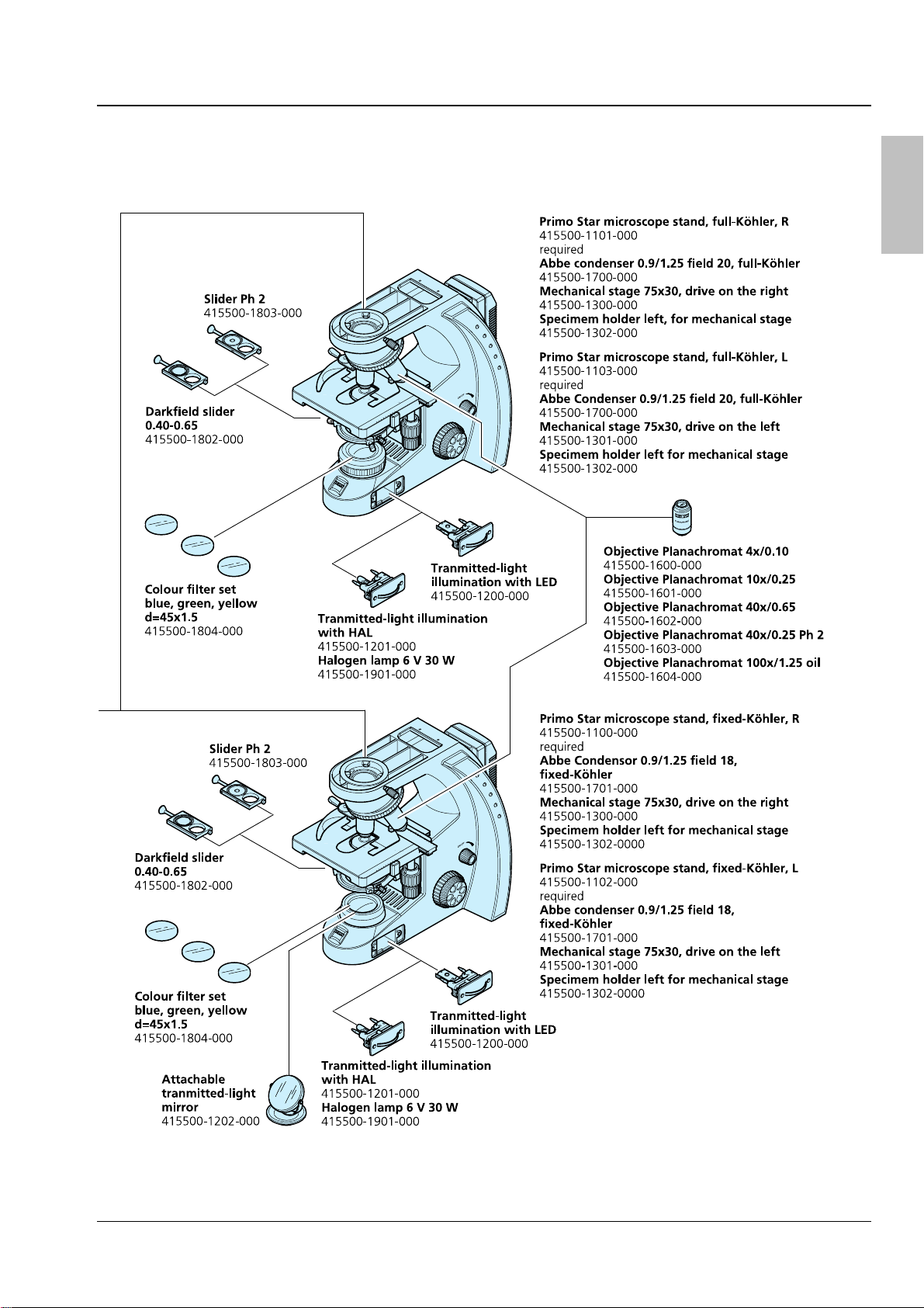
2.1 System overview
lish
8 B 46-0071 v 03/06
Primo Star Description Carl Zeiss
lish
En
B 46-0071 v 03/06 9

Carl Zeiss Description Primo Star
2.2 Total view
En
lish
1 Eyepiece
2 Binocular head
3 Tube
4 Carrying handle
5 Plug-in power unit
6 Stand
7 ON/OFF switch;
illumination
intensity
8 Illumination
module
9a Luminous-field
diaphragm,
adjustable
9b Luminous-field
diaphragm, fixed
10a Condenser carrier,
Full Köhler
10b Condenser carrier,
Fixed Köhler
11a Abbe condenser,
Full Köhler
11b Abbe condenser,
Fixed Köhler
12 Objective
13 Microscope stage
14 Objective
nosepiece
Fig. 1 Total view
10 B 46-0071 v 03/06

Primo Star Description Carl Zeiss
2.3 Intended use
The Primo Star microscope is a universally applicable light microscope primarily designed for the
examination of cell and tissue cultures as well as sediments in culture flasks, Petri dishes and microplates.
Typical applications:
Examination of blood and tissue samples from the human body, observation of intracellular
processes on living cell cultures, cell-cell interactions, motility, growth, potential measurement,
detection of medical drugs, microinjection and in vitro fertilization.
When handling hazardous substances, observe the instructions on intended operation, correct use and
statutory safety precautions.
2.4 Instrument description and main features
The Primo Star is a transmitted-light microscope of compact design with a small footprint.
Beside the high-resolution, infinity-corrected objectives and the important microscopy techniques, such as
brightfield, darkfield and phase contrast, the microscope is optionally available with a camera port for
photo and video documentation.
The major features of the microscope include:
− Modular illumination through 6V 30W halogen lamp, LED illumination or illuminating mirror.
− Integrated fixture for external power supply and cable (incl. cable with multi-standard plug and
country-specific plug adapters)
lish
En
− Plastic-coated carrying handle integrated in stand for installation, uninstallation and transport
− Blue, light-intensity indicators installed on both sides and well visible from a distance
− Stand in «Full Köhler» or «Fixed Köhler» design
− Convenient coaxial coarse and fine focusing drive, smoothness of coarse focusing drive being
adjustable
− Mechanical stage 75×30 left/right with specimen holder, stage controls optionally on the right or left
− Space-saving, continuously adjustable illumination module optionally with halogen or LED source
− «Full Köhler» or «Fixed Köhler» Abbe condensers for brightfield, darkfield and Ph 2 phase contrast
− Backward inclined quadruple objective nosepiece with W 0.8 lens thread running on ball bearing
− Infinity-corrected «Plan-ACHROMAT» objectives with magnifications of 4x, 10x, 40x and 100x/Oil for
brightfield, darkfield and Ph 2 phase contrast Ph 2 (40x/Ph2) as well as for oil immersion applications
(100x/Oil)
− Binocular tube or binocular phototube (50% vis, 50% doc) with ergonomically favorable tube angle of
30° with adjustable interpupillary distance and viewing height
− 10× focusing eyepieces for field-of-view numbers 18 or 20, suitable for spectacle wearers
B 46-0071 v 03/06 11

Carl Zeiss Description Primo Star
2.5 Objectives
En
The objectives are the optical heart of the microscope. The objectives may be labeled as follows:
lish
Plan-ACHROMAT 10×/0.25 ∞/-.
where:
10× Objective magnification,
With a defined color ring on the
objective being assigned to each
magnification step (Carl Zeiss color code)
0.25 Numerical aperture
∞ Infinite mechanical tube length
− Usable with cover slip thickness D = 0 or
0.17 mm
or
0.17 Usable with cover slip thickness
D = 0.17 mm
Other labels:
Oil Oil immersion objective
Fig. 2 Objective
Ph 2 Phase contrast objective with green
inscription and phase stop Ph 2
Objective magnification multiplied by eyepiece magnification results in overall visual magnification, e.g.
10 x 10 = 100x.
Numerical aperture multiplied by 1000, e.g. 0.25 × 1000 = 250×, presents the maximum useful
magnification; there is no resolution for further details above that limit.
When immersion objectives are used, the air between the cover slip and the objective is replaced by a
liquid, which in most cases is immersion oil. The plastic oiler containing 5 ml of immersion oil is
particularly suitable for this purpose.
Because of their short working distances, the 40×, 40x/Ph 2 and 100x/Oil objectives are equipped with
resilient mounts for specimen protection.
12 B 46-0071 v 03/06

Primo Star Start-Up and Operation Carl Zeiss
3 START-UP AND OPERATION
3.1 Starting up the microscope
Before installing and starting up the microscope, be sure to carefully read and observe the
notes on instrument safety (see Section
1).
Do not touch optical surfaces when unpacking the microscope to avoid fingerprints!
The microscope is supplied completely assembled and inclusive of accessories packed to commercial
standards. Additionally ordered components, such as sliders or transmitted-light equipment with
illuminating mirror, are packed separately.
• Remove the microscope from the transport case and place it onto the worktable.
Retain the original packaging for storage of the instrument in longer periods of non-use or for
return to the manufacturer.
• Remove the plug-in power unit (
Fig. 3/2) from
its storage fixture on the back wall of the
microscope.
• Replace the installed power outlet adapter by
one of the supplied country-specific adapters
Fig. 3/4), if necessary. To this end, pull off the
(
attached adapter and plug on the desired
adapter.
lish
En
• Connect the plug-in power unit to a power
outlet.
• If the plug-in power unit cannot be plugged
into the chosen power outlet because of limited
space, replace the power outlet adapter by the
supplied IEC adapter (
Fig. 3/3). This allows the
plug-in power unit to be put flat onto the
tabletop and connected to the power outlet
through a country-specific appliance cable.
When using the IEC adapter, the plug-in power unit can be fixed to the back wall of the
microscope stand by means of the supplied two self-adhesive hooks and the Velcro
• Turn on the microscope with rotary switch (
Fig. 3/5) and adjust the illumination to the desired
Fig. 3 Starting up the microscope
®
strip.
intensity.
The selected intensity is indicated in five steps by the blue light-emitting diodes (
Fig. 3/1) arranged on
both sides of the stand.
• At the end of the microscopic examinations, turn the microscope off with the rotary switch and cover
it with the dust cover.
• The smoothness of the coarse focusing drive (
Fig. 4/18) is factory-adjusted. However, you can readjust
it when required.
B 46-0071 v 03/06 13

Carl Zeiss Start-Up and Operation Primo Star
3.2 Controls
En
lish
Fig. 4 Controls
14 B 46-0071 v 03/06

Primo Star Start-Up and Operation Carl Zeiss
Legend to Fig. 4:
1 Eyepieces
2 Binocular body of the tube
3 Illumination-intensity indicators
4 Rotary knob for switch ON/OFF and adjustment of illumination intensity
5 Fine focusing drive (right side)
6 Coarse focusing drive (right side)
7 Control knob for X travel of mechanical stage
8 Control knob for Y travel of mechanical stage
9 Condenser clamp screw
10a Knurled ring for adjustment of luminous-field diaphragm (with Full Köhler equipment only)
10b Luminous-field diaphragm (fixed in Fixed Köhler equipment)
11a Condenser entering screws (in Full Köhler equipment: knurled screws)
11b Condenser centering screws (in Fixed Köhler equipment: Allen screws)
12 Spring lever of specimen holder
13 Knurled ring of objective nosepiece
14 Lever for the adjustment of the aperture diaphragm of the condenser
15 Knurled knob for vertical adjustment of condenser
16 Coarse focusing drive (left side)
17 Fine focusing drive (left side)
18 Knurled ring for adjusting the smoothness of the coarse focusing drive
lish
En
B 46-0071 v 03/06 15

Carl Zeiss Start-Up and Operation Primo Star
3.3 Operating the microscope
En
lish
3.3.1 Setting interpupillary distance and
viewing height
• Swing the eyepiece tubes symmetrically slightly
toward or away from one another to adjust the
distance between the tubes to your individual
interpupillary distance (
Fig. 5).
The adjustment of the interpupillary distance is
correct when you see only one round image while
Fig. 5 Setting the interpupillary distance
looking through the two eyepieces!
• Swivel the eyepiece tubes fully up (
down (
Fig. 6/B) to adjust the viewing height to
Fig. 6/A) or
your individual requirements.
Fig. 6 Adjusting the viewing height
3.3.2 Compensating for ametropia and
inserting the eyepiece pointer
The eyepieces (
over rubber eyecups (
Fig. 7/3) are equipped with fold-
Fig. 7/1: pulled out; Fig. 7/2:
folded over).
Both eyepieces are suitable for spectacle wearers.
Additionally, they contain a focusing ring for the
compensation of defective vision. The provided
diopter scale serves to facilitate finding the correct
setting.
The eyepiece pointer can be inserted in one
eyepiece, when required.
To this end, follow this procedure:
• Use Allen key SW 1 mm to loosen grub screw
(
Fig. 7/6) on the binocular body from the
bottom; remove the eyepiece.
• Unscrew the stop (
Fig. 7/5) by hand from the
eyepiece.
• Insert the eyepiece pointer (
Fig. 7/4) into the
eyepiece (with the coated side facing your
eyes). Screw in the eyepiece stop again.
• Put the eyepiece into the tube and fix it with
Fig. 7 Inserting the eyepiece pointer
the grub screw.
16 B 46-0071 v 03/06

Primo Star Start-Up and Operation Carl Zeiss
• Turn the focusing ring of the eyepiece (Fig. 7/3) to focus on the triangular figure of the eyepiece
pointer.
• Put the specimen onto the mechanical stage. Look at the specimen through the eyepiece with the
eyepiece pointer and focus on the microscopic image by turning on the focusing drive.
• When in the above-mentioned eyepiece both microscopic image and eyepiece pointer appear sharply,
focus the image for the second eye by turning the focusing ring of the second eyepiece.
Having done so, both microscopic images inclusive of the eyepiece pointer are focused.
Afterwards, you should focus on the specimen only by adjusting the focusing drive.
3.3.3 Adjusting transmitted-light
brightfield on the Full Köhler
microscope
• First, place a contrasty specimen slide with the
0.17 mm cover slip being on top in the
specimen holder of the mechanical stage. Fix
the slide by means of the spring lever
Fig. 4/12).
(
lish
En
• If the microscope stand is equipped with a
phase or dark-filed slider, pull this slider out to
the left as far as it will go.
• Turn rotary knob (
Fig. 8/1) on microscope stand
to adjust the illumination intensity.
• Move the Abbe condenser up to the top
mechanical stop by turning knurled knob
Fig. 4/15); set the control lever of the aperture
(
diaphragm (
Fig. 4/14) to mid-position.
The knurled knob for vertical
adjustment of the condenser is at the
left of the microscope, if you use the
mechanical stage 75×30 with drive on
the right, it is at the right, if the stage
controls are on the left.
• Turning at the knurled ring (
Fig. 8/6) of the
nosepiece, swing the 10x objective into the
light path.
• On the binocular tube (
Fig. 8/7), first look
through one eyepiece and turn the focusing
Fig. 8/2) to focus on the specimen.
drive (
Fig. 8 Adjusting transmitted-light
brightfield
• Then, readjust the focus for the other eye, if necessary, by turning the eye lens of the focusing
eyepiece.
• Close the luminous-field diaphragm (
of view (
Fig. 8/A).
Fig. 8/3) until it becomes visible (even if not in focus) in the field
B 46-0071 v 03/06 17

Carl Zeiss Start-Up and Operation Primo Star
• Turn the knurled knob for vertical adjustment of the condenser (Fig. 4/15) until the edge of the
En
lish
luminous-field diaphragm appears sufficiently sharp (
• Center the image of the luminous-field diaphragm using both centering screws (
condenser (
Fig. 8/D).
(
Fig. 8/C). Then, open the diaphragm until it just disappears from the field of view
Fig. 8/B).
Fig. 8/5) of the
• To adjust the aperture diaphragm (contrast), remove one eyepiece from the tube and look through the
tube with your naked eye. Swing lever (
2/3 … 4/5 of the diameter of the exit pupil of the objective (
Fig. 8/4) to adjust the aperture diaphragm to approximately
Fig. 8/E). In most applications, this
aperture diaphragm setting provides optimum contrast at almost ideal resolution, and is therefore the
best compromise for the human eye.
• Insert the eyepiece back in the tube.
Specimen field size and objective aperture change after every objective change. Therefore,
repeat the adjustment of luminous-field diaphragm and aperture diaphragm to obtain
optimum results.
3.3.4 Adjusting transmitted-light brightfield on the Fixed Köhler microscope
The Primo Star Fixed Köhler Microscope is supplied factory-adjusted. Operation is restricted to a few
manipulations.
• Place the specimen in the specimen holder of the mechanical stage.
• If the microscope stand is equipped with a phase or dark-filed slider, pull this slider out to the left as
far as it will go.
• Adjust the desired magnification by swinging in the corresponding objective.
• Set the control lever of the aperture diaphragm of the condenser to the value of the selected
magnification (10x, 40x or 100x).
• Turn the rotary knob on the microscope stand to adjust the illumination intensity to a level pleasant
for observation.
If the condenser had been removed (e.g. for installing the illuminating mirror), make sure to
reinstall and center it by means of the two centering screws (for this, refer to Section
3.4.5).
18 B 46-0071 v 03/06

Primo Star Start-Up and Operation Carl Zeiss
3.3.5 Adjusting transmitted-light phase
contrast or transmitted-light
darkfield
lish
• First, adjust the microscope as you do for
brightfield.
• Turn the nosepiece to swing the phase-contrast
objective (40x/Ph 2) into the light path.
• Open the luminous-field diaphragm (
Fig. 9/3, if
adjustable) on the stand and open the aperture
diaphragm by means of control lever (
on Abbe condenser (
• If the phase-contrast slider (
Fig. 9/2).
Fig. 9/6) was not
Fig. 9/1)
factory-installed yet, first unscrew its screw
Fig. 9/7). Then, push the slider from the left
(
into the Abbe condenser and screw the screw
Fig. 9/7) back in again.
(
• Push the slider to the right as far as it will go to
move the phase stop into the light path.
• Move the control lever of the aperture
diaphragm to fully open it on the Full Köhler
model or set it to the PH mark on the Fixed
Köhler model.
• Adjust the illumination intensity as needed.
En
Fig. 9 Inserting the slider
• Check the centering of the phase stop
according to the drawing in
Fig. 10. To this end,
remove one eyepiece and replace it by the
eyepiece telescope.
• Center the phase stop, if necessary, (
Fig. 10/A)
by turning the two adjusting screws of the
slider (
SW 1.5 (
corresponds to that shown in
Fig. 9/5) by means of the two Allen keys
Fig. 9/4) until the phase stop image
Fig. 10/B.
• Afterwards, replace the eyepiece telescope by
the eyepiece again.
For darkfield applications, use the darkfield slider in place of the phase-contrast slider.
Fig. 10 Centering the phase stop
B 46-0071 v 03/06 19
Carl Zeiss Start-Up and Operation Primo Star
3.4 Converting the microscope
En
lish
Unplug the plug-in power unit from
line power before converting the
microscope.
3.4.1 Changing the tube
Fig. 11 Changing the tube
• Loosen clamp screw (
installed tube (
approximately 90° (
side take it of upward (
For reasons of space, the tube may
Fig. 11/2), turn the
Fig. 11/1) clockwise by
Fig. 11/A) and on the right
Fig. 11/B).
also be clamped by the grub screw
with hexagonal socket head supplied
with the tube.
• Insert the tube to be installed, with the
eyepieces pointing to the right and its dovetail
mount slightly inclined, under the two holding
elements (
Fig. 11/4) in the stand.
• Then, place the tube horizontally onto the
stand. In doing so, the groove on the underside
of the tube must be located above the third
holding element (
Fig. 11/3) of the stand.
• Turn the tube counterclockwise by 45°
(eyepieces pointing frontward), align it to the
stand and tighten clamp screw (
For space-saving storage of the
Fig. 11/2).
microscope (e.g. in a cabinet) the tube
may also be rotated by 180° to the
back.
3.4.2 Inserting color filters
• Move the condenser carrier fully up by turning
the knurled screw for vertical adjustment
Fig. 4/15).
(
• Unscrew the cover cap (
luminous-field diaphragm (
Fig. 12/3) from the
Fig. 12/1).
• Put the desired filter – yellow, green or blue –
(
Fig. 12/2) onto the mounting surface of the
luminous-field diaphragm and screw the cover
cap back into place.
Fig. 12 Inserting a color filter
20 B 46-0071 v 03/06

Primo Star Start-Up and Operation Carl Zeiss
3.4.3 Replacing the 6V 30W halogen
lamp or the LED illumination
Unplug the plug-in power unit from
the power outlet and allow for a
sufficient cool-down time of the
6V 30W halogen lamp before you
replace it.
lish
En
• Loosen both fastening screws (
illumination module (
Fig. 13/1 o 2). In doing so,
Fig. 13/3) of the
slightly press the screws against the spring and
turn them by 90°: Turn left screw clockwise and
right screw counterclockwise.
• Pull the illumination module (
Fig. 13/1 or 2) out
of the stand.
• If the stand is equipped with a 6V 30W halogen
lamp (
(
Fig. 13/4) from the lamp carrier and insert the
Fig. 13/2), remove the halogen lamp
new halogen lamp. Do not touch the new lamp
with naked fingers as this will reduce lamp life.
• If the stand is equipped with an LED source,
replace the complete illumination module
including the LED (
• Push the illumination module (
Fig. 13/1).
Fig. 13/1 or 2)
back into the stand and lock it by means of the
two screws (
Fig. 13/3). In doing so, slightly press
the screws against the spring and turn them by
90°: Turn left screw counterclockwise and right
screw clockwise.
Fig. 13 Replacing the 6V 30W halogen lamp
or the LED illumination module
3.4.4 Changing objectives
• Turn the focusing drive to move the mechanical
stage fully down.
• Turn the nosepiece (
objective to be changed (
Fig. 14/3) to move the
Fig. 14/1) into a lateral
position.
• Unscrew the objective and remove it
downward.
• Screw the desired objective (
nosepiece as far as it will go.
• If you intend to insert the objective in a lens
mount not used so far, remove the dust cover
from the corresponding mount of the
nosepiece.
Fig. 14/2) into the
Fig. 14 Changing an objective
B 46-0071 v 03/06 21

Carl Zeiss Start-Up and Operation Primo Star
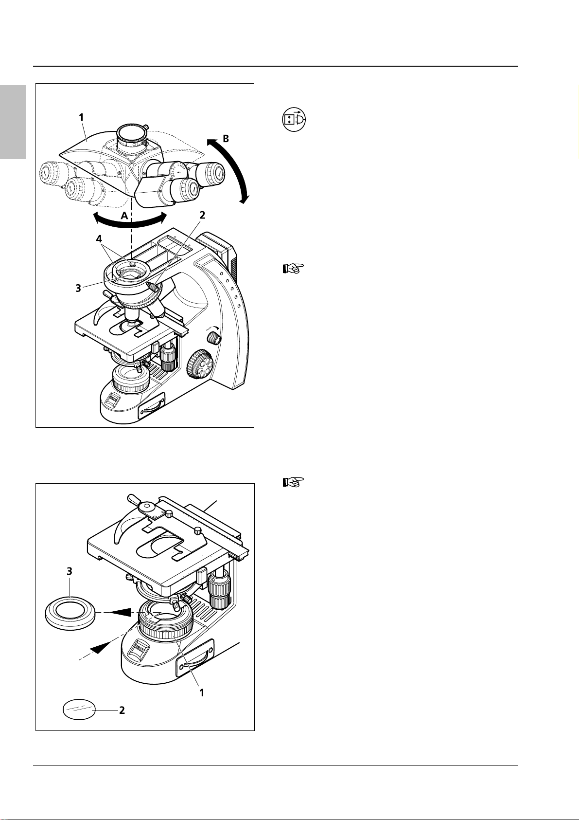
3.4.5 Installing/removing the
En
illuminating mirror
lish
Fig. 15 Removing/installing the condenser
The mirror serves to illuminate the specimen if no
power outlet is available.
It can be used only in combination with the
Primo Star Fixed Köhler Microscope. For this
purpose, it is necessary to remove the condenser
and the condenser carrier insert.
Installing the illuminating mirror:
• Remove cover cap (
field diaphragm (
Fig. 15/6) from luminous-
Fig. 15/5).
• Using an Allen key, loosen the clamp screw
Fig. 15/2) of the condenser and the centering
(
screws (
Fig. 15/4) so that the condenser (Fig. 15/7) can
(
Fig. 15/3) of the condenser carrier
be removed frontward. Remove the condenser
Fig. 15/7).
(
• Unscrew clamp screw (
from condenser carrier insert (
Fig. 15/2 or Fig. 16/1)
Fig. 15/1 or
Fig. 16/3).
Fig. 16 Installing/removing the illuminating
mirror
• Push the condenser carrier backward against
the spring and inclining it remove it upward
from the condenser carrier (
• Insert the mirror (
Fig. 16/5) from top through
Fig. 15/4).
the aperture of the condenser carrier and place
it onto the mount of the luminous-field
diaphragm (
Fig. 16/2). Take care that the mirror
rests level on the mount.
• Rotate and incline the mirror until the daylight is
reflected homogeneously into the light path.
Removing the illuminating mirror:
• Remove the mirror (
Fig. 16/5) upwards through
the aperture of the condenser carrier.
• Slightly incline the condenser carrier insert
Fig. 15/1 or Fig. 16/3) to insert it in the
(
aperture of the condenser carrier. In doing so,
press the unit backward against the spring and
place it horizontally onto the condenser carrier.
• Screw the condenser clamp screw (
into the condenser carrier insert.
Fig. 16/1)
22 B 46-0071 v 03/06

Primo Star Start-Up and Operation Carl Zeiss
• Taking care that the locating screw on the rear side of the condenser fits in groove (Fig. 16/4) of the
condenser carrier insert, put the condenser into this insert.
• Screw the cover cap back onto the luminous-field diaphragm.
• To center the condenser, connect the microscope to the power outlet and switch it on.
• Turn the nosepiece to swing the 4x objective into the light path.
lish
En
• Turn the two centering screws (
Fig. 15/3) to adjust the illuminated image symmetrically to the edge of
the field of view.
3.4.6 Installing a camera
You can install a digital camera, a video camera or
a compact digital camera to your choice on the
microscope via the available camera adapters (see
Section
• First, install the photo tube (
• Loosen clamp screw (
2.1).
necessary (refer to Section
Fig. 17/8) and remove the
Fig. 17/7), if
3.4.1).
dust cap from the photo tube.
Installing a compact digital camera
• Sliding mount (
M37/52 (
Fig. 17/3) and lens mount (Fig. 17/6)
Fig. 17/4), thread adapter ring
are supplied premounted as Digital Camera
Adapter P95 M37/52×0.75. The opposite
drawing shows this unit dismantled.
Furthermore, you may unscrew the M37/52
thread adapter (
sliding mount (
Fig. 17/3) (not shown) from the
Fig. 17/4) so that you can also
mount cameras with M37 thread.
• Mount the adapter ring (
with the camera) to the camera (
Fig. 17/2) (supplied
Fig. 17/1) (see
the operating instructions of the camera).
Fig. 17 Installing a camera
• Screw the unit consisting of sliding mount (
mount (
Fig. 17/6) into the adapter ring (Fig. 17/2).
Fig. 17/4), thread adapter ring M37/52 (Fig. 17/3) and lens
• Insert the camera with adapter into the photo tube as far as it will go. Align it and fasten it with clamp
screw (
Fig. 17/8).
B 46-0071 v 03/06 23

Carl Zeiss Start-Up and Operation Primo Star
• Depending on the microscope equipment or the camera used, it may be necessary to optimize the
En
lish
distance between camera lens and lens mount (
necessary in particular, if it is impossible to obtain an unvignetted image in any of the zoom positions
Fig. 17/6) (see double-headed arrow). This will be
of the camera lens. To this end, adjust the camera as follows:
− Switch off the autofocus.
− Set the object distance to ∞.
− Set aperture-priority auto exposure mode.
− Choose an aperture as large as possible (i.e. small aperture value!).
Not all the cameras provide these options. Please consult the Operating Manual of the used camera.
• Loosen grub screw (
Fig. 17/5).
• Vary the camera lens/lens mount distance gradually, i.e. displace the sliding mount with camera on
lens mount in defined steps.
• Zoom the camera lens through from wide angle (W) to tele position (T).
• Carry out this test until the image is format filling without masking or vignetting.
• Retighten the grub screw (
With camera/adapter combinations that have not been recommended expressly by Zeiss, it
Fig. 17/5).
may be quite impossible to obtain an unvignetted image.
Installing a digital camera or video camera with C-mount thread
Cameras with C-mount thread are to be connected to the phototube of the microscope by means of the
camera adapter P95-C 2/3” 0.65x or P95-C ½” 0.5x (
• Put the camera (
Fig. 17/10) together with the corresponding camera adapter (Fig. 17/9) into the
phototube as far as it will go, align it and fasten it by means of the clamp screw (
Fig. 17/9).
Fig. 17/8).
24 B 46-0071 v 03/06

Primo Star Care and Troubleshooting Carl Zeiss
4 CARE AND TROUBLESHOOTING
4.1 Instrument care
Care of the microscope is restricted to the following operations:
• Cover the instrument with the dust cover after every use.
• Do not install the microscope in a humid room; maximum humidity < 75%.
• Cover open tubes with the dust caps.
• Remove dust and loose dirt from visible optical surfaces with a brush, blower brush, cotton bud,
optics cleaning tissue, or a cotton cloth.
• Remove water-soluble dirt (coffee, cola, etc.) by blowing on it and subsequent wiping it off with a
cloth moistened with water to which you may also add a mild detergent.
• Wipe off stubborn oily or fatty dirt (immersion oil, fingerprints) with a cotton bud or a lint-free cotton
cloth and the optics cleaning solution L.
The cleaning solution consists of 90 vol% gasoline and 10 vol% isopropanol (IPA). Its individual
constituents are also known as:
Gasoline: Medical alcohol, petrolether
Isopropanol: 2-Propanol,
Dimethylcarbinol,
2-Hydroxypropane
Clean optical surfaces by polishing in circles starting in the middle and moving to the edges using slight
pressure only.
lish
En
For the use in humid climatic zones, all optical components of the microscope are provided with
protection against fungus attack.
B 46-0071 v 03/06 25

Carl Zeiss Care and Troubleshooting Primo Star
4.2 Troubleshooting
En
lish
The field of view is not
completely visible.
Problem Cause Remedy
Nosepiece with objective has not been
switched into click-stop position.
Condenser has not been set correctly. Set condenser correctly.
Switch nosepiece with objective into
click-stop position.
Low resolving power, poor
image contrast
The aperture diaphragm has not been
adjusted correctly.
The luminous-field diaphragm has not
been adjusted correctly.
The filter has not been inserted
correctly in the filter mount.
The aperture diaphragm has not been
opened to the correct size.
Condenser not focused correctly. Focus the condenser.
Wrong cover slip thickness selected
for use of transmitted-light objectives
corrected for 0.17mm cover slips.
Use of no or non-specified immersion
oil with immersion objective
Air bubbles in immersion oil Remove the bubbles by applying new oil
Immersion oil on the front lens of a
dry objective.
Dirt or dust on the optical surfaces of
objectives, eyepieces, condenser, or
filters
Adjust aperture diaphragm correctly.
Adjust luminous-field diaphragm
correctly.
Insert filter correctly into filter mount.
Set opening of aperture diaphragm to
correct size.
Use standard 0.17 mm cover slips.
Use the supplied immersion oil.
or moving the objective to and fro.
Clean the front lens of the dry objective.
Clean the respective optical
components.
Greater focus differences after
changing the objective
the LED source does not light
up although the microscope
has been switched on.
The 6V 30W halogen lamp is
flickering, its light intensity
unstable, the illumination
inhomogeneous
Stage comes down by itself,
image focus is unstable
The focusing eyepieces have not been
set correctly.
Power plug has not been plugged into
power outlet.
6V 30W halogen lamp or LED source is
defective.
End of average service life of 6V 30W
halogen lamp has been reached.
Power cable Incorrectly installed or
broken power cable
The pins of the 6V 30W halogen lamp
have not been inserted correctly in the
lamp holder.
The pins of the 6V 30W halogen lamp
have not been inserted symmetrically
in the lamp holder.
Adjusted torque of coarse focusing
drive is too low.
Set the focusing eyepieces to the
corresponding defective vision.
Connect power plug to power outlet. The 6V 30W halogen lamp or
Replace the defective 6V 30W halogen
lamp or the LED module
Replace the 6V 30W halogen lamp.
Connect the power cable correctly or
replace it.
Insert the pins of the 6V 30W halogen
lamp correctly in the lamp holder.
Insert the pins of the 6V 30W halogen
lamp symmetrically in the lamp holder.
Increase the torque of the coarse
focusing drive to make motion stiffer.
26 B 46-0071 v 03/06

Primo Star Appendix Carl Zeiss
5 APPENDIX
5.1 Technical data
Dimensions (width x depth x height)
Stand with binocular tube
Stand with phototube
With tube / phototube turned by 180°
approx. 190 x 425 x 395 mm
approx. 190 x 425 x 395 mm
approx. 190 x 375 x 395 mm
Weight
Primo Star with phototube 8.2 kg
Ambient conditions
Transport (in packaging):
Permissible ambient temperature
Storage:
Permissible ambient temperature
Permissible humidity
(no condensation)
Operation:
Permissible ambient temperature
Permissible humidity
(no condensation)
Atmospheric pressure
-40 to +70 °C
+10 to +40 °C
max. 75% at 35 °C
+5 to +40 °C
max. 75% at 35 °C
800 hPa to 1060 hPa
Operating data
lish
En
Protection Class
Protection Type
Electrical safety
Pollution degree
Overvoltage category
Radio interference suppression
Line voltage
Line frequency
Power consumption
Output of plug-in power unit
Microscope 12V/6V DC
Light sources
Halogen lamp
Adjustability of light source
Color temperature at 6V
Luminous flux
Average service life
Luminous area
II
IP20
in compliance with DIN EN 61010-1 (IEC 61010-1)
including CSA and UL directives
2
II
in accordance with EN 61326
100 to 240 V (±10 %) wide-range input power supply, i.e. the
voltage setting of the instrument need not be changed!
50 / 60 Hz
70 VA; secondary voltage of external power supply 12V
12 V DC; max. 2.5A
1.5V – 6V adjustable
HAL 6V 30W
continuous, from 1.5 to 6V DC
2800 K
280 lm
1000 h
1.5 x 3 mm
B 46-0071 v 03/06 27

Carl Zeiss Appendix Primo Star
En
lish
Constant, brightness-independent
color temperature of
Homogeneous field illumination
Suitable for objectives with
magnifications of
Analogous brightness adjustment from
LED illumination
Optical/mechanical data
Stand with stage focusing
With coarse focusing drive
With fine focusing drive
Total stage lift
Objective change Manual via quadruple objective nosepiece
Objectives Infinity-corrected objective range with W 0.8 mounting thread
Eyepieces
With field-of-view number 18
With field-of-view number 20
Specimen stage
Dimensions (width x depth)
Stage travel (X x Y)
Coaxial drive
Vernier scales
Specimen holder
7480 K
20 mm diameter
4x to 100x
approx. 15 to 100%
4 mm/revolution
0.5 mm/revolution
15 mm
30 mm tube size
PL 10x/18 Br. foc.
PL 10x/20 Br. foc.
Mechanical stage 75×30 right/left
140 x 135 mm
75 x 30 mm
Optionally right or left
Readable from the right
With spring lever, left
Abbe condenser 0.9/1.25, fixed collector For V
Abbe condenser 0.9/1.25 For V
Binocular tube 30°/20
Maximum field-of-view number
Interpupillary distance
Tube angle
Viewing height
Viewing port
Binocular phototube 30°/20
Maximum field-of-view number
Interpupillary distance
Tube angle
Viewing height
Viewing port
Photo/video port
Light path selection with swing-in prism
. 4x to 100x
obj
. 4x to 100x
obj
20
Adjustable from 48 to 75 mm
30°
380 to 415 mm
Tube factor 1x
20
Adjustable from 48 to 75 mm
30°
380 to 415 mm
Tube factor 1x
Tube factor 1x, 60 mm mount
50% vis / 100% doc
Illuminating mirror With plane surface and spherical surface with f’ = 75 mm
28 B 46-0071 v 03/06

Primo Star Inhaltsübersicht Carl Zeiss
INHALTSÜBERSICHT
Seite
1 Hinweise zur Gerätesicherheit …………………………………………………………………………….. 4
1.1 Allgemeine Sicherheitshinweise ……………………………………………………………………………….. 4
1.2 Gerätesicherheit und EMV………………………………………………………………………………………. 4
1.3 Auspacken, Transportieren, Lagern…………………………………………………………………………… 5
1.4 Entsorgen…………………………………………………………………………………………………………….. 5
1.5 Bedienen……………………………………………………………………………………………………………… 5
1.6 Garantiehinweise…………………………………………………………………………………………………… 7
2 Gerätebeschreibung……………………………………………………………………………………………. 8
2.1 Systemübersicht ……………………………………………………………………………………………………. 8
2.2 Gesamtansicht…………………………………………………………………………………………………….. 10
2.3 Verwendungszweck …………………………………………………………………………………………….. 11
2.4 Gerätebeschreibung und Hauptmerkmale………………………………………………………………… 11
2.5 Objektive……………………………………………………………………………………………………………. 12
Deutsch
3 Inbetriebnahme und Bedienung ………………………………………………………………………… 13
3.1 Mikroskop in Betrieb nehmen………………………………………………………………………………… 13
3.2 Bedienelemente…………………………………………………………………………………………………… 14
3.3 Mikroskop bedienen…………………………………………………………………………………………….. 16
3.3.1 Okularabstand und Einblickhöhe einstellen………………………………………………………………. 16
3.3.2 Augenfehlsichtigkeit am Okular ausgleichen und Okularzeiger einsetzen………………………. 16
3.3.3 Durchlicht-Hellfeld am Mikroskop Full-Köhler einstellen ……………………………………………… 17
3.3.4 Durchlicht-Hellfeld am Mikroskop Fixed-Köhler einstellen …………………………………………… 18
3.3.5 Durchlicht-Phasenkontrast oder Durchlicht-Dunkelfeld einstellen …………………………………. 19
3.4 Mikroskop umrüsten ……………………………………………………………………………………………. 20
3.4.1 Tubus wechseln…………………………………………………………………………………………………… 20
3.4.2 Farbfilter einsetzen ………………………………………………………………………………………………. 20
3.4.3 Halogenlampe 6 V / 30 W bzw. LED-Beleuchtung wechseln………………………………………… 21
3.4.4 Objektiv wechseln ……………………………………………………………………………………………….. 21
3.4.5 Spiegel ein- und ausbauen…………………………………………………………………………………….. 22
3.4.6 Kamera ansetzen…………………………………………………………………………………………………. 23
4 Pflege und Störungsbeseitigung………………………………………………………………………… 25
4.1 Gerät pflegen……………………………………………………………………………………………………… 25
4.2 Störungsbeseitigung…………………………………………………………………………………………….. 26
5 Anhang…………………………………………………………………………………………………………….. 27
5.1 Technische Daten ………………………………………………………………………………………………… 27
B 46-0071 v 03/06 3

Carl Zeiss Hinweise zur Gerätesicherheit Primo Star
1 HINWEISE ZUR GERÄTESICHERHEIT
1.1 Allgemeine Sicherheitshinweise
Bitte machen Sie sich vor Inbetriebnahme des Mikroskops mit dem Inhalt dieser Bedienungsanleitung
gründlich vertraut.
Ergänzende Informationen erhalten Sie von unserem Service oder von autorisierten Vertretungen.
Deutsch
Zur Gewährleistung einer sicheren Arbeitsweise und ungestörten Funktion des Mikroskops sind
unbedingt die in der Bedienungsanleitung angegebenen Vorsichtsmaßnahmen und Warnungen zu
beachten.
Diese sind im laufenden Text durch Symbole gekennzeichnet:
VORSICHT
Bei Nichtbeachtung der Sicherheitshinweise besteht eine Gefahr für den Benutzer.
ACHTUNG
Dieses Symbol kennzeichnet eine Gefahr, die für das Gerät oder Gerätesystem entstehen kann!
ACHTUNG
Vor Eingriff in das Mikroskop Steckernetzteil vom Netz trennen!
HINWEIS
Arbeitshinweise, die beim Umgang mit dem Mikroskop zu beachten sind.
1.2 Gerätesicherheit und EMV
Das Mikroskop Primo Star wurde entsprechend der Norm DIN EN 61010-1 (IEC 61010-1) und
IEC 61010-2-101 «Sicherheitsbestimmungen für elektrische Mess-, Steuer-, Regel- und Laborgeräte“,
konstruiert, gefertigt und geprüft.
Das Mikroskop Primo Star erfüllt die Anforderungen der EG-Richtlinie 98/79/EG Anhang 1 und ist mit
dem
— Zeichen gekennzeichnet.
Funkentstörung nach EN 55011 Klasse B
Störfestigkeit nach DIN EN 61326
Die Geräte werden gemäß der WEEE-Richtlinie 2002/96/EG entsorgt.
4 B 46-0071 v 03/06
Loading…
Микроскоп операционный Carl Zeiss TIVATO 700 — это инновационная система визуализации, позволяющая решать сложные задачи в нейрохирургии. Он имеет расширенные возможности визуализации, что позволяет применять современные терапевтические методики. Продвинутые режимы обеспечивают безупречное качество изображения в детализированном формате.
Главным преимуществом хирургического прибора TIVATO-700 является апохроматическая оптика, которая обеспечивает четкую передачу структурных и цветовых данных. На ее основе возможна интраоперационная флуоресценция, основанная на принципе четырех критериев:
- INFRARED 800. Исследование сосудистых соединений во время хирургических манипуляций на артериально-венозных сосудах и при сосудистых аневризмах головного мозга.
- FLOW 800. Оценка динамической скорости кровяной циркуляции и измерение уровня флуоресцентной интенсивности.
- BLUE 400. Выявление границ новообразований, имеющих злокачественное течение, с помощью технологии флуоресцентного пятна.
- YELLOW 560. Окрашивание необходимых для исследования областей флуоресцентными красителями. Окрашенные области приобретают желто-зеленый оттенок, а участки, не подвергшиеся окрашиванию, подсвечиваются естественным цветом.
Благодаря этому решению, все наиболее используемые инструменты находятся под рукой у хирурга. Также стоит отметить возможность операционного аппарата визуализировать изображения в 4-мерном формате высокого качества. Любой хирургический процесс транслируется в мельчайших деталях, чему способствует встроенная видеокамера, выдающая изображение в нужном формате и проецирующая его на широкоформатный экран.
Модель нейрохирургического микроскопа отличается максимальной гибкостью и маневренностью. Это достигается за счет плеча, имеющего «плавающую» конструкцию. Оно может подниматься на необходимую высоту, позволяя проводить все виды операций. Диапазон рабочего расстояния составляет 200-625 мм, что облегчает работу с длинными инструментами и обеспечивает непрерывный режим фокусировки.
Кроме того, прибор оснащен функциями AutoBalance, обеспечивающей балансировку в автоматическом режиме, и AutoDrape — автоматическое зачехление. Эти функции облегчают подготовку оборудования к эксплуатации.
TIVATO700 от Карл Зейц — это современный мощный микроскоп, в основе которого лежит апохроматическая оптика. В совокупности с расширенным функционалом и разнообразием режимов создается целая система для решения сложных хирургических задач. Высокое качество изображения, детализированная визуализация, эргономичная конструкция, разработанная специально для пользователей — все это объединено в одном устройстве от немецкого производителя.
Стоимость аппарата определяется его модификацией и конфигурацией. Специалисты помогут определиться с выбором и подскажут точную цену выбранного товара.
Технические характеристики
Страна изготовления
Германия
Рабочее расстояние, мм
200 — 625
Видеокамера
4К
ZEISS INFRARED 800
+
ZEISS YELLOW 560
+
Доставка и оплата
ОПЛАТА
Оплата покупок производится удобным для Вас способом: наличными или безналичными средствами на расчетный счет организации, с предоставлением всех необходимых документов, предусмотренных законодательством Российской Федерации.
Оплата также возможна следующими способами:
— в терминале транспортной компании (наложенный платеж);
— на сайте интернет-магазина «Бравокислород» с помощью платежной системы ROBOKASSA.
При оформлении заказа в нашем интернет-магазине возможна покупка товара в кредит с помощью сервиса «Купи в кредит» от банка АО «Тинькофф».
Доставка
Доставка возможна в день заказа!
Бесплатная доставка при заказе от 20 000 рублей.
Уважаемые Покупатели, транспортировка товаров осуществляется бесплатно по России.
Мы работаем с 17-ю транспортно-логистическими компаниями и курьерскими службами (DHL, EMS Почта России и другие) и из 17 вариантов подберем и предложим Вам самый оптимальный способ доставки в Ваш город.
Все товары из нашего ассортимента можно забрать самовывозом, предварительно оформив заказ.
Узнайте сроки доставки, позвонив на номер 8 (343) 346-7-500, 8 (800) 700-75-61 (звонок бесплатный) или напишите нам, и наши менеджеры свяжутся с Вами в ближайшие несколько минут.
Другие преимущества микроскопа:
- Быстрая регулировка фокусного расстояния всего одним пальцем с помощью объектива Zeiss Varioskop 230;
- Удобная коммуникация с пациентом благодаря приложению Zeiss Connect App с функцией Smart Recording, которые записывают и загружают данные в локальную сеть или по Wi-Fi, а также позволяют делиться фотографиями или видео в мессенджерах или соцсетях;
- Возможность моментального редактирования фотографий.
EXTARO 300 Premium можно приобрести с дополнительными модулями для получения идеального изображения:
- Fluorescence Mode — точное обнаружение кариозных поражений за счет флуоресцентного света и увеличения изображения
- NoGlare Mode — подавление световых бликов на поверхности зуба позволяет диагностировать мелкие нюансы, например, изменение цвета.
- TrueLight Mode — комфортное освещение для замедления затвердевания композитных материалов дает больше времени на моделирование зуба.
Технические характеристики
- Система увеличения: ручной апохроматический переключатель увеличения
- Увеличение: 0.4x, 0.6x, 1.0x, 1.6x, 2.5x
- Окуляры: 12.5-кратные или 10-кратные широкопольные окуляры
- Тубус: с изменяемым углом наклона 180°
- Фокусировка: объектив Varioskop 230, рабочее расстояние 200–430 мм
- Освещение: светодиодное, 5500 К
- Функция LightBoost — уровни интенсивности освещения, эквивалентные ксеноновому источнику света
- Пользовательский интерфейс: эргономичный джойстик управления, регулировка освещения и рабочего расстояния одним пальцем
Базовая комплектация EXTARO 300 Premium:
- Голова микроскопа с 5-ступенчатым увеличением;
- Встроенный вариоскопический объектив Varioskop 230;
- Регулируемый на 180⁰ бинокулярный тубус;
- Светодиодное освещение TriLED с функцией LightBoost;
- Оранжевый светофильтр для работы с композитными материалами;
- Зеленый светофильтр для контраста при работе с мягкими тканями;
- MORA-интерфейс, позволяющий отклонять голову микроскопа относительно бинокулярного тубуса на +/- 25°;
- Моторизированная апертура светового пучка Spot Light для изменения диаметра светового поля;
- Расширенная визуализация для подключения флюоресцентного модуля и модуля TrueLight без оранжевого спектра;
- Интегрированная Full HD видеокамера (1080p) со встроенным модулем Wi-Fi.
Дополнительные опции:
1. Флюоресцентный модуль подсвечивает (контрастирует) разными цветами в ротовой полости: здоровые ткани зубов, кариозные полости, композитные реставрации, мягкие ткани.
2. Модуль TrueLight Mode специально разработан для применения в стоматологии. Предотвращает преждевременное затвердевание полимерных (композитных) материалов, при этом сохраняет естественный цвет и глубину освещения (без оранжевого спектра). Включает в себя опцию NoGlare Mode (антибликовый фильтр), который позволяет убрать блики с отражающих поверхностей и увидеть скрытые детали.
3. Набор асепсиса включающий в себя:
- Адаптерное кольцо для установки защитных линз объектива
- Защитные нестерильные линзы объектива VisionGuard (10 шт)
- Силиконовая насадка на Вариоскоп (2 шт)
- Силиконовые насадки на ручки управления (2 шт)
- Силиконовые насадки на джойстик (6 шт)
- Силиконовые насадки на переключатели увеличения (6 шт)
- Силиконовые насадки на регулятор межзрачкового расстояния (6 шт)
Carl Zeiss EXTARO 300 Essential – микроскоп, объединивший в себе невероятное качество и четкость изображения. Это уникальное оборудование, позволяющее производить даже самые сложные манипуляции в области стоматологии и хирургии. Различные режимы визуализации выводят стоматологическую практику на совершенно иной качественный уровень!
Представленная модель объединяет в себе возможности новейших технологий и качественно превосходит конкурентов. Наличие мобильного приложения позволяет демонстрировать пациентам состояние полости рта до и после лечения, выделять области, требующие особого внимания и своевременного вмешательства. Данная функция позволит пациентам принимать быстрые решения относительно лечения.
Заказать прибор можно в базовой или расширенной комплектации. По желанию клиента конструкцию можно дополнить беспроводной педалью, фильтром для работы с лазером, поворотным кольцом и т.п. Менять настройки можно одной рукой, не отрываясь от рабочего процесса. Центральный джойстик управления качественно упрощает процесс оказания помощи пациентам.
Применение микроскопа значительно повышает эффективность оказываемых услуг, делает работу врача более комфортной и удобной. Устройство подходит как для стоматологической практики, так и применения в области хирургии.
Получить подробную консультацию, а также задать интересующие вопросы можно нашим консультантам по указанным телефонам. Доставка оборудования осуществляется во все регионы страны.
Передача данных при помощи приложения ZEISS Connect
Камера микроскопа с высоким разрешением позволяет записывать и загружать видеоматериалы в локальную сеть или в мобильное приложение ZEISS Connect по беспроводной сети. При помощи мобильного приложения ZEISS Connect вы можете показывать пациентам изображения исходного и текущего состояния полости рта, а также выделять области, требующие лечения. Это поможет пациентам принимать обоснованные решения.
Преимущества:
- Работа одной рукой со специального джойстика, встроенного в микроскоп;
- Складной тубус Foldable tube обеспечивает простую регулировку фокусного расстояния в диапазоне 200–430 мм;
- Усиленное увеличение с функцией Promag;
- Естественный свет благодаря светодиодной лампе TriLED.
Микроскоп EXTARO 300 модели Essential имеет несколько возможных вариантов крепления: настенное, потолочное и мобильное.
Имеется возможность заказа модели, имеющей раздвижной тубус с удлинителем.
Данная модель микроскопа не имеет возможности дальнейшего дооснащения модулями.
Базовая комплектация EXTARO 300 Essential
- Голова микроскопа с 5-ступенчатым увеличением;
- Varioskop 230 — встроенный вариоскопический объектив, позволяющий менять фокусное расстояние от 200 до 430 мм;
- Светодиодное освещение TriLED;
- Оранжевый светофильтр для работы с полимерными материалами;
- Зеленый светофильтр для работы с мягкими тканями;
- Моторизированная апертура светового пучка Spot Light позволяет менять диаметр светового поля;
- Интегрированная Full HD видеокамера с функцией записи фото-видеоматериалов с выходом HDMI, карта памяти USB и пульт управления.
- Система увеличения: ручной апохроматический переключатель увеличения
- Увеличение: 0.4x, 0.6x, 1.0x, 1.6x, 2.5x
- Окуляры: 12.5-кратные широкопольные окуляры с диоптрийной настройкой -8/+5
- Имеется возможность регулировки отдаленности глаза от оптики
- Фокусировка: объектив Varioskop 230, рабочее расстояние 200–430 мм
- Освещение: светодиодное, 5500 К
- Пользовательский интерфейс: эргономичный джойстик управления, регулировка освещения и рабочего расстояния одним пальцем.
Рецензии
Еще нет отзывов об этом товаре.