
Здравствуйте.
Мой первый небольшой обзор будет посвящен тестеру напряжения компьютерных блоков питания. Для кого-то эта штука окажется годной, так как позволяет протестировать приличное количество БП за короткое время, для кого-то это будет игрушкой, так как есть вольтметр, и всякие HWiNFO64, правды тут не найти. Я решил поиграться, и заказал себе его.
Начнем с упаковки. Пришел тестер завернутый в некий вспененный материал (забыл название), и на экране наклеена пленка, так что суровые будни Почты России врят ли что сделают с ним.
Сборку можно описать двумя словами — не развалится. Половинки корпуса приплавлены друг к другу (посему разборки не будет), есть коцки, и неровности. По разъемам можно придраться только к обоим Молексам, сидят они кривовато, но использованию это не мешает. В остальном все отлично, ножки не погнуты, качество нормальное.
Для общего развития — разъемы БП с вики:

Вилки шлейфов питания (из блока питания), без переходников и адаптеров
1) AMP 171822-4 мини-размера для питания 5 и 12 вольтами периферийного устройства (обычно, дисковод)
2) Molex обычного размера (molex 8981)
3) 5-контактные разъёмы MOLEX 88751 для питания устройства с интерфейсом SATA: корпус MOLEX 675820000 или эквивалентный с контактами Molex 675810000 или эквивалентными[3]
4) «PCIe8connector» для питания видеокарты, расщепляемый на «PCIe6connector» (для питания видеокарты)
5) «PCIe6connector» для питания видеокарты
6) «EPS12V» (англ. Entry-Level Power Supply Specification для питания процессора
7) «ATX PS 12V» («P4 power connector») для питания процессора
«ATX12V» основного питания материнской платы: MOLEX 39-01-2040 или эквивалентная с контактами Molex 44476-1112 (HCS) или эквивалентными
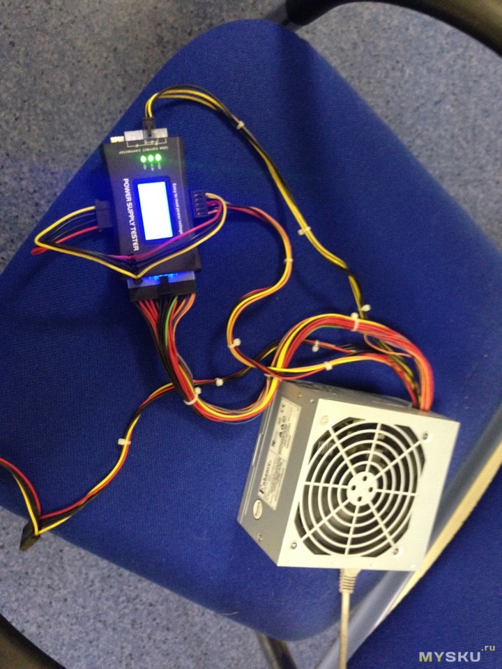
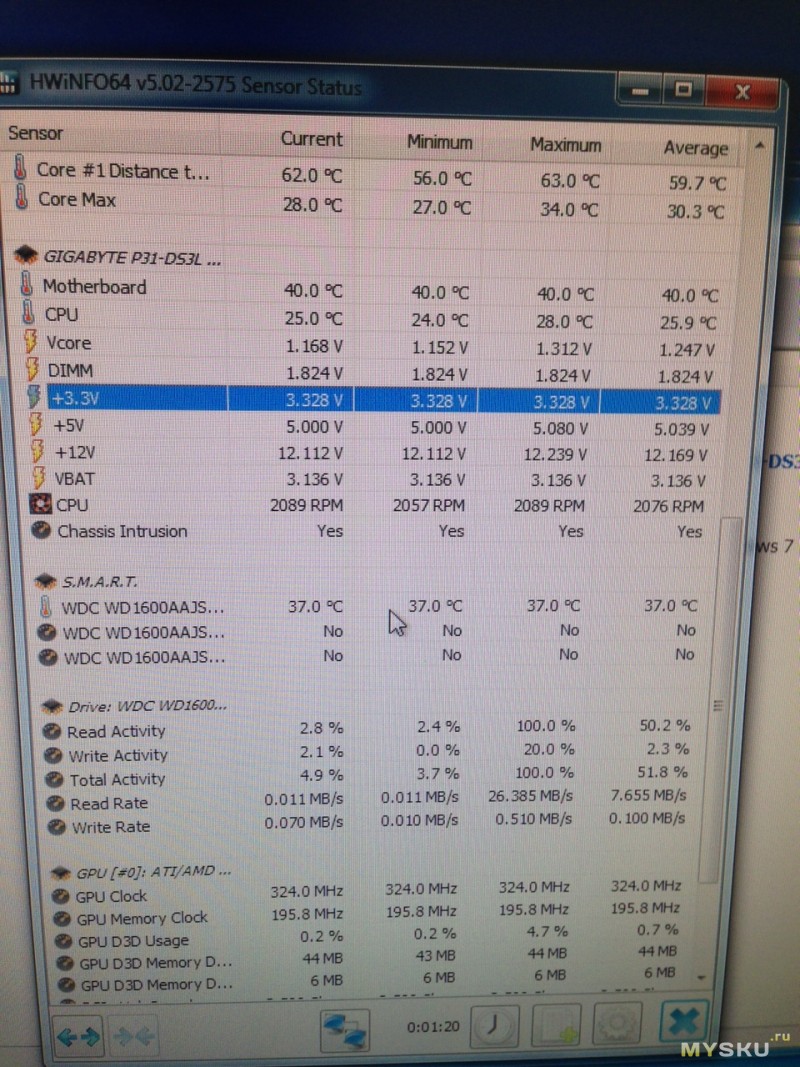
Тестирование исправного БП. Тут описывать особо нечего, сверка будет производится не вольтметром, а программным способом, с помощью HWiNFO64. Мамка исправная, и датчики не косячат. Хочу заметить, что при подключении БП к питанию вместе с тестером, на блок питания подается сигнал о включении, и он, собственно, включается. Так что замеры тестер производит при включенном БП.
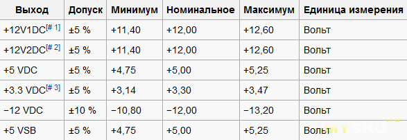
Допуски:
PG же это Power Good, задержка в миллисекундах — система защиты БП, которая дает возможность сформировать напряжение требуемого уровня. Должно быть в пределах 230-270.
К сожалению, в программе не отображаются половина линий, но думаю этого хватит.
Вполне себе интересная игрушка, которая может стать полезным инструментом. Я вот, наконец, разберу свои завалы из старых БП на работе.
upd
Пользователь stasv предоставил фотки внутренностей своего сгоревшего тестера, за что ему спасибо:
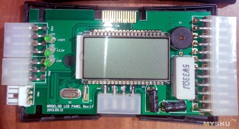
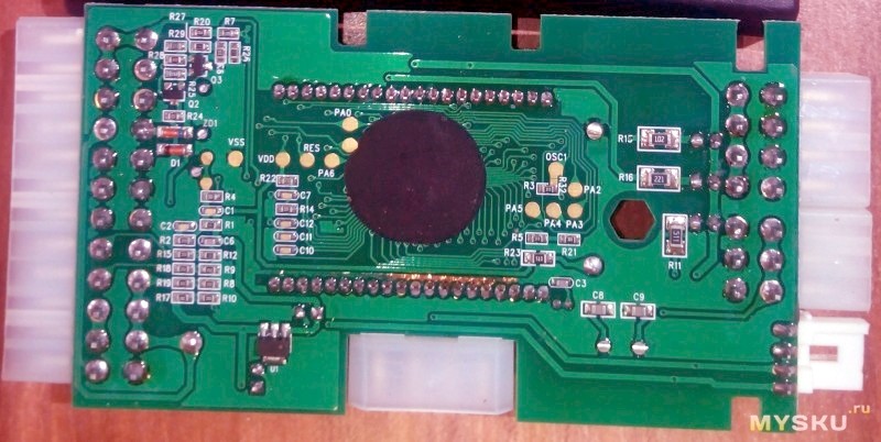
Как можно заметить, установлен простой резистор на 5W и 33 Ом. В принципе, этого и следовало ожидать. Серьезные замеры им не провести, само собой, но для отбраковывания очевидной некондиции за быстрое время более чем достаточно, как мне кажется.
- Информация о материале
-
-
Просмотров: 5034
Для проверки работоспособности блока питания компьютера можно использовать power supply tester китайских производителей. При подключении вы увидите значения напряжений, которые можете сравнить с диапазоном допустимых значений.
Подключается он обычно как показано ниже:
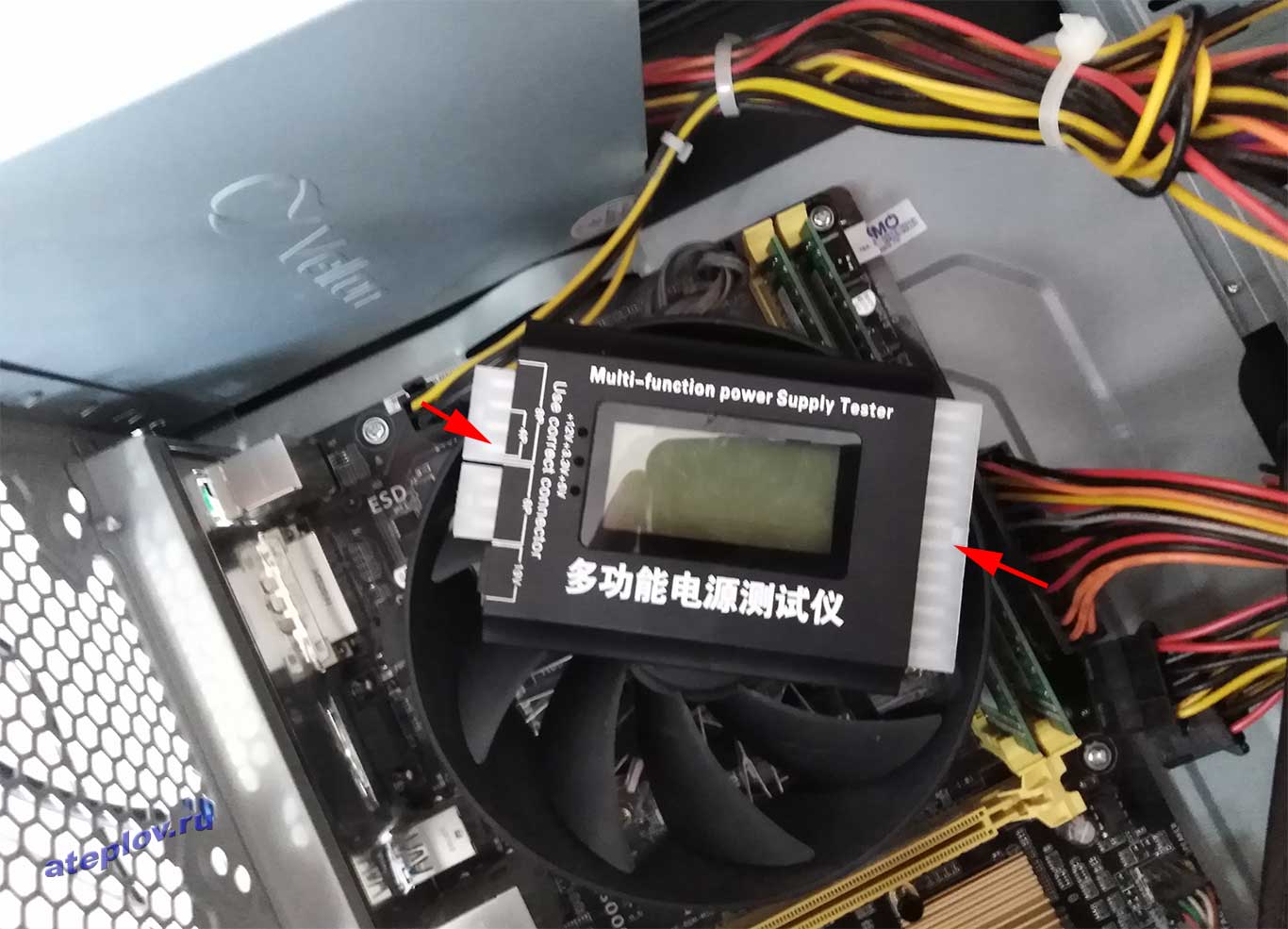
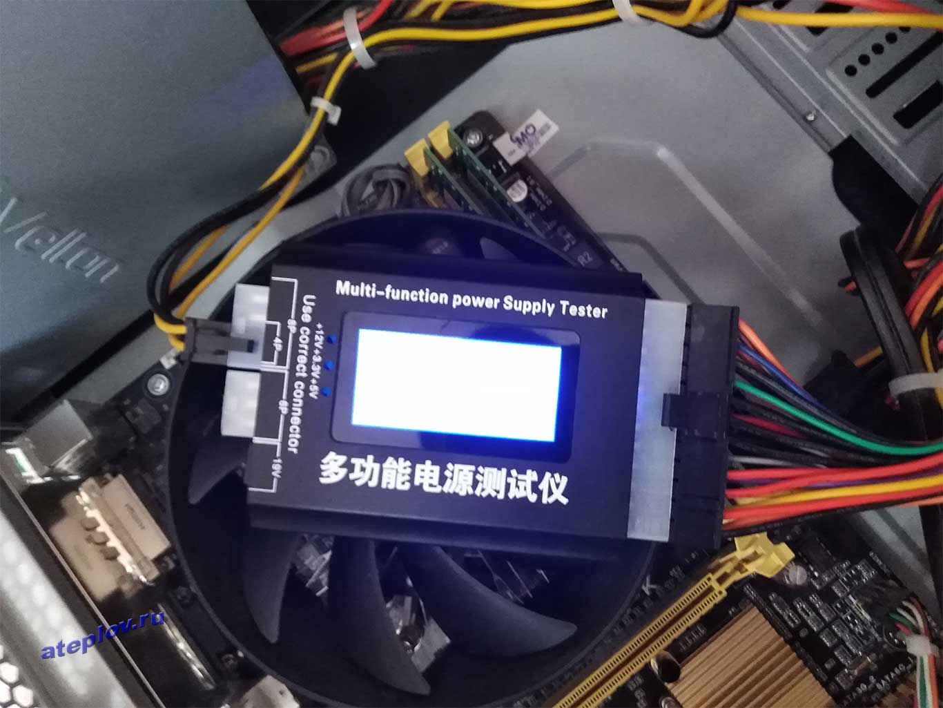
При необходимости слева подключается дополнительное питание видеокарты вместо питания для процессора.
| Параметр напряжения | Допустимое отклонение,+-% | Минимальное значение,В | Нормальное значение,В | Максимальное значение,В |
| +12VDC | 5 | 11.4 | +12.00 | +12.6 |
| +5VDC | 5 | 4.75 | +5.00 | +5.25 |
| +3.3VDC | 5 | 3.14 | +3.30 | +3.47 |
| -5VDC | 10 | -4.50 | -5.00 | -5.50 |
| -12VDC | 10 | -10.80 | -12.00 | -13.20 |
| +5VSB | 5 | +4.75 | +5.00 | +5.25 |
Проверка блока питания китайским тестером.
Автор: admin / 6 июля 2018 / Рубрика: Обзоры
Привет! Продолжаем говорить о компьютерных железках и способах их диагностики. Те, кому постоянно приходится сталкиваться с ремонтами и настройкой компьютеров знают, что любая проблема решается гораздо быстрее если под рукой есть правильный инструмент. Поэтому выкладываю небольшой обзор китайского тестера блока питания — Power Supply Tester.
Правильное питание — залог здоровья! И это касается не только нас с вами, но и наших компьютеров. Вот и проверим как хорошо этот тестер разбирается в компьютерной диете.
Вообще, я уже выкладывал статью о том как протестировать блок питания с помощью мультиметра, но не все они достаточно компактны, чтобы постоянно носить их с собой. Да и в удобстве использования и наглядности метод с мультиметром явно проигрывает. Что касается точности измерений, то это выясним далее.
Прошло всего пару недель после заказа тестера на Aliexpress и вот посылка у меня на руках (ссылка на тестер — http://aliexpress.com/power_supply_tester)
Как видно устройство достаточно компактно. Разъемы питания процессора и дополнительного питания видеокарты подписаны, для избежания некорректного подключения. Всю нужную информацию прибор выводит на дисплей, а также может сигнализировать о неполадках писком через встроенный спикер.
Для проверки достаточно подключить тестер к разъемам блока питания и включить сам блок в розетку. После этого БП стартует и на дисплее тестера отображаются показатели по разным линиям напряжения. Заметьте, что с таким тестером не требуется никаких лишних движений со скрепками.
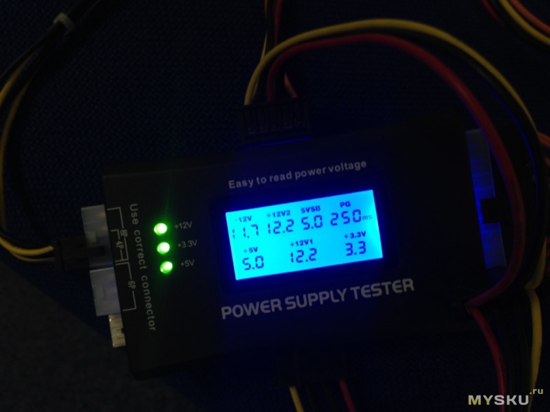
На дисплее можно увидеть показатели основных напряжений +5V, +12V, +3.3V (нижний ряд), думаю, тут не нужно пояснений. А также:
- -12V используется в основном для COM-портов.
- +12V (обозначен как +12V2) берется с разъема питания процессора, или доп. питания видеокарты, если их подключать поочередно. Обратите внимание, что все разъемы подписаны — 4 pin, 6pin, 8pin.
- +5VSB — дежурное питание. Линия должна иметь напряжение +5 вольт ±5%. Поддерживает питание устройств, которые должны быть включены постоянно, даже когда компьютер находится в спящем режиме.
- PG — в данном случае время до получения сигнала Power_Good, после которого подается питание на процессор. В интернете нашел информацию, что значение должно быть в диапазоне 100 — 500 мс, (у всех протестированных мной БП это значение было близко к 300 мс). Если это значение будет слишком большим, то компьютер с таким блоком питания может не стартануть. Если блок питания совсем не выдает напряжение PG, то тестер начинает пищать и на дисплее моргает соответствующий показатель.
Для наглядности выложу таблицу допустимых диапазонов напряжений по линиям.
В результате проверки мультиметром всех основных показатели напряжений, расхождения составили несколько сотых вольта (простительно, так как он округляет до десятых), из чего я сделал вывод, что китайский Power Supply Tester неплох. Вот пара фотографий в качестве доказательств.
Дежурное питание (5VSB)
Чуть не забыл. Данный тестер проверяет блок питания без нагрузки, поэтому во время тестов обязательно подключайте хотя бы пару вентиляторов. Если при подключении потребителя напряжение на какой-либо из линий падает, то скорее всего высохли конденсаторы и такой блок не будет работать.
Как видно прибор достаточно информативен и прост в использовании и отлично подойдет начинающим диагностам компьютерных неполадок. Я даже убежден, что пользоваться таким тестером сможет каждый пользователь. Конечно, по детальности измерений он не сравниться с обычным мультиметром, но в большинстве случаев этого и не требуется. Его вполне достаточно чтобы определить что «пациент скорее жив, чем мертв». ? Именно эту информацию и хотят услышать от нас владельцы компьютеров.
Как итог, считаю, что Power Supply Tester полностью оправдывает свою стоимость, поэтому добавлю его в свои инструменты.
Сегодня мы с Вами будем говорить о том, как проверить блок питания компьютера? Проверку мы будем проводить с помощью двух разных измерительных приборов: мультиметра (мультитестера) и одной китайской «приспособы» Ими мы проведем необходимые измерения и попытаемся выявить неисправность блока питания компьютера. Будем надеяться, что с помощью данных приборов проверка блока питания пройдет не только успешно, но и познавательно!
Начнем, как и положено, с небольшой предыстории. Был в нашем IT отделе случай: рабочая станция пользователя включалась раза с третьего-четвертого. Потом — совсем перестала загружаться. Вообщем — «классика жанра», все вентиляторы крутятся, но после включения — черный экран.
Грешим на неисправность блока питания. Как же нам с Вами проверить блок питания компьютера? Давайте извлечем его из корпуса, автономно запустим и померяем напряжения на его выходе.
Как уже упоминалось, проведем проверку блока питания двумя разными измерительными приборами: одним безымянным китайским устройством и самым обычным мультиметром долларов за 10-15. Так мы сразу убьем двух зайцев: научимся работать с этими измерителями и сравним их показания между собой.
Предлагаю начать с простого правила: напряжения блока питания надо проверять, предварительно нагрузив чем-то сам БП. Дело в том, что без «нагрузки» мы будем получать неточные (немного завышенные) результаты измерений (а оно нам надо?). Согласно рекомендациям стандарта для блоков питания без подключения к ним нагрузки они вообще не должны запускаться.
Конечно, (в случае проведения замеров мультиметром) можно и не отключать БП от материнской платы компьютера (сохранив, тем самым, для него рабочую нагрузку), но тогда я просто не смогу нормально сфотографировать для Вас сам процесс измерений
Итак, предлагаю нагрузить наш БП обычным 8-ми сантиметровым внешним вентилятором на 12V (можно — двумя), который мы на время проверки блока питания подключим к «Molex» разъему испытуемого. Вот так:
При необходимости слева подключается дополнительное питание видеокарты вместо питания для процессора.
Таблица допустимых значений для Power supply tester
| Параметр напряжения | Допустимое отклонение,+-% | Минимальное значение,В | Нормальное значение,В | Максимальное значение,В |
| +12VDC | 5 | 11.4 | +12.00 | +12.6 |
| +5VDC | 5 | 4.75 | +5.00 | +5.25 |
| +3.3VDC | 5 | 3.14 | +3.30 | +3.47 |
| -5VDC | 10 | -4.50 | -5.00 | -5.50 |
| -12VDC | 10 | -10.80 | -12.00 | -13.20 |
| +5VSB | 5 | +4.75 | +5.00 | +5.25 |
Сегодня мы с Вами будем говорить о том, как проверить блок питания компьютера? Проверку мы будем проводить с помощью двух разных измерительных приборов: мультиметра (мультитестера) и одной китайской «приспособы» Ими мы проведем необходимые измерения и попытаемся выявить неисправность блока питания компьютера. Будем надеяться, что с помощью данных приборов проверка блока питания пройдет не только успешно, но и познавательно!
Начнем, как и положено, с небольшой предыстории. Был в нашем IT отделе случай: рабочая станция пользователя включалась раза с третьего-четвертого. Потом — совсем перестала загружаться. Вообщем — «классика жанра», все вентиляторы крутятся, но после включения — черный экран.
Грешим на неисправность блока питания. Как же нам с Вами проверить блок питания компьютера? Давайте извлечем его из корпуса, автономно запустим и померяем напряжения на его выходе.
Как уже упоминалось, проведем проверку блока питания двумя разными измерительными приборами: одним безымянным китайским устройством и самым обычным мультиметром долларов за 10-15. Так мы сразу убьем двух зайцев: научимся работать с этими измерителями и сравним их показания между собой.
Предлагаю начать с простого правила: напряжения блока питания надо проверять, предварительно нагрузив чем-то сам БП. Дело в том, что без «нагрузки» мы будем получать неточные (немного завышенные) результаты измерений (а оно нам надо?). Согласно рекомендациям стандарта для блоков питания без подключения к ним нагрузки они вообще не должны запускаться.
Конечно, (в случае проведения замеров мультиметром) можно и не отключать БП от материнской платы компьютера (сохранив, тем самым, для него рабочую нагрузку), но тогда я просто не смогу нормально сфотографировать для Вас сам процесс измерений
Итак, предлагаю нагрузить наш БП обычным 8-ми сантиметровым внешним вентилятором на 12V (можно — двумя), который мы на время проверки блока питания подключим к «Molex» разъему испытуемого. Вот так:
А вот так выглядит наш китайский тестер (вещь в себе) для проверки БП о котором я говорил раньше:

Как видите, устройство без названия. Надпись «Power Supply Tester» (тестер электропитания) и — все. Но нам название не обязательно, нам надо чтобы он замеры производил адекватно.
Я подписал основные коннекторы, с которых может снимать показания данное устройство, поэтому здесь — все просто. Единственно, перед тем как начинать проверку блока питания компьютера убедитесь в том, что правильно подключили дополнительный 4-х контактный штекер на 12V. Он используется при подключении блока питания к соответствующему разъему возле центрального процессора.
Давайте разберем этот момент подробнее. Вот интересующая нас часть устройства крупным планом:

Внимание! Видите предупреждающую надпись «Use correct connector»? (используйте подходящий коннектор). При неправильном подключении мы не то что правильно проверить блок питания не сможем, мы сам измеритель угробим ! На что тут нужно обратить внимание? На подсказки: «8P (пин)», «4P (пин)» и «6P (пин)»? К 4-х пиновому разъему подключается 4-х контактный (12-ти вольтовый) штекер питания процессора, к «6P» — шести контактный разъем дополнительного питания (к примеру — видеокарты), к «8P», соответственно, — 8-ми контактный. Только так и никак иначе!
Давайте посмотрим, как проверить блок питания данным устройством в «боевых» условиях? Вскрываем системный блок, внимательно подключаем к тестеру нужные нам коннекторы и смотрим на экран с результатами замеров.

На фото выше мы можем видеть на цифровом табло показатели замера. Предлагаю по порядку разобрать их все. Прежде всего, стоит обратить внимание на три зеленых светодиода слева. Они указывают на наличие напряжения по основным линиям: 12, 3,3 и 5V.
По центру на экране отображается числовой результат измерений. Причем отображаются как плюсовые значения, так и значения напряжения со знаком «минус».
Давайте еще раз посмотрим на фото выше и слева направо пройдемся по всем показаниям, тестера при проверке блока питания компьютера.
- — 12V (в наличии — 11,7V) — в норме
- + 12V2 (в наличии 12,2V) — ток на отдельном 4-х контактном разъеме возле процессора)
- 5VSB (5.1V) — здесь V=Вольт, SB — «standby» (дежурное напряжение — «дежурка»), с номиналом в 5В, которые устанавливаются на заданном уровне не позднее чем через 2 секунды после включения блока в сеть.
- PG 300ms — сигнал «Power Good». Измеряется в миллисекундах (ms). О нем поговорим чуть ниже
- 5V (есть 5.1V) — линии, которые служат для подачи энергии на жесткие диски, оптические приводы, дисководы и другие устройства.
- + 12V1 (12.2V) — которые подаются на основной (20 или 24-х контактный коннектор) и коннекторы дисковых устройств.
- + 3,3 V (в наличии — 3,5V) — используется для подачи питания на платы расширения (также присутствует на коннекторе SATA).
Это мы произвели проверку блока питания, который был полностью исправен (чтобы набить руку), так сказать Теперь вопрос, как проверить блок питания компьютера, который вызывает у нас подозрения? С него эта статья и начиналась, помните? Снимаем БП, «вешаем» к нему нагрузку (вентилятор) и подключаем к нашему тестеру.

Обратите внимание на выделенные области. Мы видим что напряжения БП компьютера по линиям 12V1 и 12V2 составляют 11,3 V (при номинале в 12V).
Хорошо это или плохо? Спросите Вы Отвечаю: согласно стандарту, есть четко заданные границы допустимых значений, которые считаются «нормальными». Все что в них не вписывается — иногда тоже замечательно работает, но зачастую — глючит или не включается вообще
Для наглядности — вот таблица допустимого разброса напряжений:
Первая колонка показывает нам все основные линии, которые есть в БП. Столбец «Допуск» это — максимально допустимое отклонение от нормы (в процентах). Согласно с ним, в поле «мин» указывается минимально допустимое значение по данной линии. Столбец «ном» приводит номинальный (рекомендуемый показатель, согласно стандарту). И — «макс» — максимально допустимое.
Как видите, (на одной из предыдущих фотографий) наш результат замера по линиям 12V1 и 12V1 равен 11,30V и он не вписывается в стандартный пятипроцентный разброс (от 11,40 до 12,60V). Данная неисправность блока питания, по видимому, и приводит к тому, что компьютер не включается вообще или запускается с третьего раза.
Итак, неисправность, вызывающую подозрения мы обнаружили. Но как произвести дополнительную проверку и убедиться, что проблема именно в заниженном напряжении +12V? С помощью нашего (самого обычного) мультиметра под маркой «XL830L».
Как проверить блок питания с помощью мультиметра?
Запускать блок будем замыкая два контакта (пина) скрепкой или куском проволоки подходящего диаметра.
Теперь — подсоединяем к БП внешний вентилятор (помним про «нагрузку») и — кабель 220V. Если мы все сделали правильно, то внешний вентилятор и «карлсон» на самом блоке начнут вращаться. Картина, на этом этапе, выглядит следующим образом:

На фото выделены приборы, с помощью которых мы будем проверять блок питания. Работу тестера из поднебесной мы уже рассматривали в начале статьи, теперь произведем те же измерения, но уже с помощью цифрового мультиметра.
Здесь нужно немного отвлечься и рассмотреть поближе сам разъем БП компьютера. Точнее — те напряжения, которые в нем присутствуют. Как мы можем видеть (на одном из предыдущих фото) он состоит из 20-ти (или же — 24-ти четырех) проводов разного цвета.
Эти цвета употреблены не просто так, а обозначают весьма определенные вещи:
- Черный цвет это — «земля» (COM, он же — общий провод или — масса)
- Желтый цвет + 12V
- Красный: + 5V
- Оранжевый цвет: +3,3V
Предлагаю проверить и рассмотреть каждый пин отдельно:

Так — гораздо нагляднее, не правда ли? Про цвета Вы помните, да? (черный, желтый, красный и оранжевый). Это — основное, что нам надо запомнить и понять, прежде чем самостоятельно проверять блок питания. Но есть еще несколько пинов, на которые нам надо обратить внимание.
В первую очередь это провода:
- Зеленый PS-ON — при замыкании его с «землей» блок питания запускается. На схеме это показано, как «БП Вкл.». Именно эти два контакта мы замыкаем с помощью скрепки. Напряжение на нем должно быть 5V.
- Далее — серый и передаваемый по нему сигнал «Power Good» или — «Power OK». Также 5V (смотрите в примечании)
- Сразу за ним — фиолетовый с маркировкой 5VSB (5V Standby). Это — пять вольт дежурного напряжения (дежурка). Оно подается в компьютер даже тогда, когда он выключен (кабель на 220V должен быть, естественно, подключен). Это нужно, к примеру, для того, чтобы иметь возможность отправить удаленному компьютеру по сети команду на запуск «Wake On Lan».
- Белый (минус пять Вольт) — сейчас практически не используется. Раньше служило для обеспечения током плат расширения, устанавливаемых в ISA слот.
- Голубой (минус двенадцать Вольт) — на данный момент потребляют интерфейсы «RS232» (COM порт), «FireWire» и некоторые PCI платы расширения.
Перед тем, как проверять блок питания мультиметром, рассмотрим еще два его разъема: дополнительный 4-х контактный для нужд процессора и «Molex» коннектор, для подключения жестких дисков и оптических приводов.
Здесь мы видим знакомые уже нам цвета (желтый, красный и черный) и соответствующие им значения: + 12 и + 5V.
Для большей наглядности скачайте себе полную расшифровку всех напряжений БП отдельным архивом.
Сейчас давайте с Вами убедимся, что полученные нами теоретические знания вполне подтверждаются на практике. Каким же образом? Предлагаю начать с внимательного изучения заводского «стикера» (наклейки) на одном из реальных блоков питания стандарта ATX.

Обратите внимание на то, что подчеркнуто красным. «DC OUTPUT» (Direct Current Output — выходное значение постоянного тока).
- +5V=30A (RED) — плюс пять В, обеспечивает силу тока в 30 Ампер (красный провод) Мы ведь помним из текста выше, что по красному у нас поступает именно +5V?
- +12V=10A (YELLOW) — по плюс двенадцать В мы имеем силу тока в десять Ампер (ее провод — желтый)
- +3.3V=20A (ORANGE) — линия три и три десятых В может выдержать силу тока в двадцать Ампер (оранжевый)
- -5V (WHITE) — минус пять В — по аналогии с описанным выше (белый)
- -12V (BLUE) — минус двенадцать В (голубой)
- +5Vsb (PURPLE) — плюс пять В дежурное (Standby). О нем мы уже говорили выше (он — фиолетовый).
- PG (GRAY) — сигнал Power Good (серый).
На заметку: если, к примеру, дежурное напряжение согласно замерам равно не пяти вольтам, а, скажем, — четырем, то, весьма вероятно, что мы имеем дело с проблемным стабилизатором напряжения (стабилитроном), который следует заменить на аналогичный.
И последняя запись из списка выше говорит нам, что максимальная выходная мощность изделия в ваттах равна 400W, причем только каналы в 3 и 5V суммарно могут обеспечить 195 Ватт.
Примечание: «Power Good» — «питание соответствует норме». Напряжение от 3-х до 6-ти Вольт (номинал — 5V) вырабатывается после необходимых внутренних проверок через 100 — 500 ms(миллисекунд, получается — от 0,1 до 0,5 секунды) после включения. После этого микросхема тактового генератора формирует сигнал начальной установки центрального процессора. Если он отсутствует, то на материнской плате возникает другой сигнал — аппаратного сброса ЦП, не позволяя компьютеру работать при нештатном или нестабильном питании.
Если выходные напряжения не соответствуют номинальным (например, при его снижении в электросети), сигнал «Power Good» пропадает и процессор автоматически перезапускается. При восстановлении всех необходимых значений тока «P.G.» формируется заново и компьютер начинает работать так, как будто его только что включили. Благодаря быстрому отключению сигнала «Power Good» ПК “не замечает” неполадок в системе питания, поскольку останавливает работу раньше, чем могут появиться ошибки и другие проблемы, связанные с его нестабильностью.
В правильно спроектированном блоке выдача команда «Power Good» задерживается до стабилизации питания по всем цепям. В дешевых БП эта задержка недостаточна и процессор начинает работать слишком рано, что, само по себе, может даже привести к искажению содержимого CMOS-памяти.
Вот теперь, вооружившись необходимыми теоретическими знаниями, мы понимаем как правильно проверить блок питания компьютера с помощью мультитестера. Выставляем предел измерений по шкале постоянного тока в 20 Вольт и приступим к проверке блока питания.
Черный «щуп» тестера прикладываем к черному проводу «земля», а красным начинаем «тыкать» во все оставшиеся
Примечание: не волнуйтесь, даже если Вы что-то не так начнете «щупать», то ничего не сожжете — просто получите не верные результаты измерений.
Итак, что мы видим на экране мультиметра в процессе проверки блока питания?
По линии +12V напряжение в 11,37V. Помните, китайский тестер показал нам 11,3 (в принципе, — похожее значение). Но все равно не дотягивает до минимально допустимого в 11,40V.
Обратите внимание также на две полезные кнопки на тестере: «Hold» — удержание показаний измерений на табло и «Back Light» — подсветка экрана (при работе в плохо освещенных помещениях).
Что мы делаем дальше? Предлагаю также снять замер с «Molex» разъема и с провода в +12V.

Видим — те же (не внушающие доверия) 11,37V.
Теперь (для полноты картины) нам нужно проверить блок питания на предмет соответствия номиналу других значений. Протестируем, к примеру, пять Вольт на том же «Molex-е».

Черный «щуп» к «земле», а красный — к красному пятивольтовому пину. Вот результат на мультиметре:
Как видим — показатели в норме. Аналогично производим замеры всех остальных проводов и сверяем каждый результат с номиналом из полной расшифровки.
Таким образом, проверка блока питания показала, что устройство имеет сильно заниженное (относительно номинала) напряжение +12V. Давайте, для наглядности еще раз промеряем эту же линию (желтый цвет на дополнительном 4-х контактном разъеме) у полностью исправного устройства.
Видим — 11,92V (помним что минимально допустимое значение здесь у нас — 11,40V). Значит в допуск вполне укладываемся.
Но проверить блок питания компьютера это еще — пол дела. Надо его после этого еще и отремонтировать, а этот момент мы разбирали в одной из предыдущих статей, которая называлась проблемы с блоком питания.
Надеюсь, что теперь Вы сами, при необходимости, сможете проверить блок питания компьютера, будете точно знать, какие именно напряжения должны присутствовать на его выводах и действовать, в соответствии с этим.
Avaya
Power Supplies — Models 1151B1 and 1151B2 Инструкция по эксплуатации
Популярность:
758 просмотры
Подсчет страниц:
3 страницы
Тип файла:
Размер файла:
330 Kb

IP Office
Installation Manual
40DHB0002USCL – Issue 9 (28th October 2003)

Page 2 — Contents
Contents
Introduction ……………………………………………………………………………………………………………………………….5
General …………………………………………………………………………………………………………………………………………………….5
Scope of Manual ……………………………………………………………………………………………………………………………………..5
IP401 Compact Office Platform …………………………………………………………………………………………….5
General …………………………………………………………………………………………………………………………………………………….6
IP401 Compact Office — Front View………………………………………………………………………………………………………. 7
Port connections…………………………………………………………………………………………………………………………………………………………….. 7
IP401 Compact Office — Rear View ………………………………………………………………………………………………………. 8
Port connections…………………………………………………………………………………………………………………………………………………………….. 8
Typical Configuration ……………………………………………………………………………………………………………………………………………………..9
IP403 Office Platform …………………………………………………………………………………………………………….10
General …………………………………………………………………………………………………………………………………………………..10
Expansion Modules ………………………………………………………………………………………………………………………………………………………10
Integral Modules (Optional)…………………………………………………………………………………………………………………………………………. 10
IP403 Office — Front View …………………………………………………………………………………………………………………….. 11
Port connections…………………………………………………………………………………………………………………………………………………………… 11
IP403 Office — Rear View………………………………………………………………………………………………………………………12
Port connections…………………………………………………………………………………………………………………………………………………………… 12
Typical Configuration ……………………………………………………………………………………………………………………………………………………13
IP406 Office Platform …………………………………………………………………………………………………………….14
General …………………………………………………………………………………………………………………………………………………..14
Expansion Modules ………………………………………………………………………………………………………………………………………………………14
Integral Modules (Optional)…………………………………………………………………………………………………………………………………………. 14
IP406 Office — Front View …………………………………………………………………………………………………………………….. 15
Port connections…………………………………………………………………………………………………………………………………………………………… 15
IP406 Office — Rear View………………………………………………………………………………………………………………………16
Port connections…………………………………………………………………………………………………………………………………………………………… 16
Typical Configurations …………………………………………………………………………………………………………………………………………………. 17
IP412 Office Platform …………………………………………………………………………………………………………….18
General …………………………………………………………………………………………………………………………………………………..18
Expansion Modules ………………………………………………………………………………………………………………………………………………………18
Integral Modules (Optional)…………………………………………………………………………………………………………………………………………. 18
IP412 Office — Front View …………………………………………………………………………………………………………………….. 19
Port connections…………………………………………………………………………………………………………………………………………………………… 19
IP412 Office — Rear View………………………………………………………………………………………………………………………20
Port connections…………………………………………………………………………………………………………………………………………………………… 20
Typical Configurations …………………………………………………………………………………………………………………………………………………. 21
Expansion Modules ……………………………………………………………………………………………………………….23
IP400 Digital Terminal 16/30………………………………………………………………………………………………………………..23
Front View (30 Port version)……………………………………………………………………………………………………………………………………….. 23
Rear View (all versions) ……………………………………………………………………………………………………………………………………………….23
IP400 Digital Stations 16/30 …………………………………………………………………………………………………………………24
IP400 Phone 8/16/30…………………………………………………………………………………………………………………………….24
Front View (30 port version) ………………………………………………………………………………………………………………………………………..24
Rear View (all versions) ……………………………………………………………………………………………………………………………………………….24
IP400 So8………………………………………………………………………………………………………………………………………………. 25
Front View……………………………………………………………………………………………………………………………………………………………………… 25
Rear View ………………………………………………………………………………………………………………………………………………………………………25
IP400 WAN3…………………………………………………………………………………………………………………………………………..26
Front View……………………………………………………………………………………………………………………………………………………………………… 26
Rear View ………………………………………………………………………………………………………………………………………………………………………26
IP400 Analog Trunk 16 ………………………………………………………………………………………………………………………… 27
Front View……………………………………………………………………………………………………………………………………………………………………… 27
Rear View ………………………………………………………………………………………………………………………………………………………………………27
Country Variants …………………………………………………………………………………………………………………….28
Page 2 — Contents IP Office Installation Manual
40DHB0002USCL – Issue 9 (28th October 2003)

Contents — Page 3
IP400 Office Systems ……………………………………………………………………………………………………………………………28
Integral Module Kits ……………………………………………………………………………………………………………………………… 29
Trunk Module Kits…………………………………………………………………………………………………………………………………. 29
Power Supplies……………………………………………………………………………………………………………………………………… 30
IP Office Rack Mounting Kits ……………………………………………………………………………………………………………….31
Expansion Modules………………………………………………………………………………………………………………………………. 31
Preparing for Installation………………………………………………………………………………………………………32
Introduction …………………………………………………………………………………………………………………………………………….32
Tools & Parts Required………………………………………………………………………………………………………………………… 32
Space requirements……………………………………………………………………………………………………………………………… 33
Environmental requirements ………………………………………………………………………………………………………………..33
Power Supply requirements ………………………………………………………………………………………………………………… 34
Grounding………………………………………………………………………………………………………………………………………………. 35
Protective Ground …………………………………………………………………………………………………………………………………………………………35
Functional Ground ……………………………………………………………………………………………………………………………………………………….. 35
Out of Building Telephone Installations ………………………………………………………………………………………………36
Rack Mounting Barrier Boxes …………………………………………………………………………………………………………………………………….. 37
Installing a New System………………………………………………………………………………………………………..38
Unpacking ……………………………………………………………………………………………………………………………………………… 38
Initial Assembly……………………………………………………………………………………………………………………………………… 39
Installation of Integral Modules…………………………………………………………………………………………………………………………………… 40
Installation of Voice Compression Modules (VCM)………………………………………………………………………………………………….. 41
Dual Modem Module……………………………………………………………………………………………………………………………………………………. 42
Rack Mounting Assembly Instructions ……………………………………………………………………………………………………………………….43
IP401 Compact Office Wall Mounting ………………………………………………………………………………………………… 44
IP401 Expansion and Installation of Integral Modules ………………………………………………………………………45
Basic System Programming ………………………………………………………………………………………………..46
Introduction …………………………………………………………………………………………………………………………………………….46
Programming Tools………………………………………………………………………………………………………………………………. 46
PC to IP Office LAN Port Connection ………………………………………………………………………………………………………………………… 46
Initial Programming ………………………………………………………………………………………………………………………………. 47
Using the IP Office Installation Wizard:……………………………………………………………………………………………………………………… 47
Using the IP Office Manager Application: ………………………………………………………………………………………………………………….48
Software Upgrades………………………………………………………………………………………………………………………………………………………. 49
Telephone Installation …………………………………………………………………………………………………………..51
Checking Telephones…………………………………………………………………………………………………………………………… 51
Connecting & Testing IP Office Telephones ……………………………………………………………………………………………………………..51
Connecting & Checking Two-Wire Telephones ………………………………………………………………………………………………………..52
Power Fail Telephones and Sockets ………………………………………………………………………………………………………………………….52
Wall Mounting 2000 Series Telephones……………………………………………………………………………………………..53
Wall Mounting 44/4600, 2420 & 6400 Series Telephones………………………………………………………………..55
System Handover……………………………………………………………………………………………………………………56
Checklist ………………………………………………………………………………………………………………………………………………… 56
Safety and Homologation Statements ………………………………………………………………………………57
Lithium Batteries ……………………………………………………………………………………………………………………………………57
Lightening Protection/Hazard Symbols………………………………………………………………………………………………. 57
Electromagnetic Interference Information …………………………………………………………………………………………..58
Federal Communications Commission (FCC) ………………………………………………………………………………………………………….. 58
Canadian Department of Communications (DOC)…………………………………………………………………………………………………… 58
89/336/ EEC (EMC Directive) CISPR 22:1993 including A1 + A2, AS/NZ 3548:1995 (ROW)…………………………… 58
Trunk Interface Modules………………………………………………………………………………………………………………………. 59
Rest Of World (ROW) ………………………………………………………………………………………………………………………………………………….. 59
USA/Canada…………………………………………………………………………………………………………………………………………………………………. 59
Further Information and Product Updates………………………………………………………………………………………….. 60
Support Telephone Numbers ……………………………………………………………………………………………………………………………………… 60
Regulatory Instructions for Use ……………………………………………………………………………………………………………61
IP Office Operation in Australia …………………………………………………………………………………………………………………………………..61
IP Office Operation in Canada……………………………………………………………………………………………………………………………………. 61
IP Office Installation Manual Contents — Page 3
40DHB0002USCL – Issue 9 (28th October 2003)

Page 4 — Contents
IP Office Operation in EU …………………………………………………………………………………………………………………………………………….62
IP Office Operation in New Zealand …………………………………………………………………………………………………………………………..62
IP Office Operation in USA ………………………………………………………………………………………………………………………………………….62
Technical Data…………………………………………………………………………………………………………………………63
Port Pinouts ……………………………………………………………………………………………………………………………………………63
Analog Trunk Ports (RJ45) ………………………………………………………………………………………………………………………………………….63
Power Fail and POT Ports (RJ45) ……………………………………………………………………………………………………………………………… 63
DS/DT Ports (RJ45) ……………………………………………………………………………………………………………………………………………………..63
ISDN Port – BRI (RJ45) ……………………………………………………………………………………………………………………………………………….63
ISDN Port – PRI (RJ45) ……………………………………………………………………………………………………………………………………………….64
LAN Port – 10/100 BaseT ……………………………………………………………………………………………………………………………………………64
DTE Port (25 Way or 9 Way D-Type socket) …………………………………………………………………………………………………………….64
Audio Port (3.5mm Stereo Jack Socket) …………………………………………………………………………………………………………………… 65
Expansion Port (RJ45 Socket)……………………………………………………………………………………………………………………………………. 65
External Control Port (3.5mm Stereo Jack Socket) ………………………………………………………………………………………………….65
WAN Port (37 Way D-Type Socket)…………………………………………………………………………………………………………………………… 66
Cables ……………………………………………………………………………………………………………………………………………………. 67
DTE Cable …………………………………………………………………………………………………………………………………………………………………….. 67
DT Line Cord for Structured Cabling …………………………………………………………………………………………………………………………. 68
PRI/BRI ISDN Cable …………………………………………………………………………………………………………………………………………………….69
LAN Interconnect Cable………………………………………………………………………………………………………………………………………………. 70
LAN Cable ……………………………………………………………………………………………………………………………………………………………………..71
LAN Crossover Cable………………………………………………………………………………………………………………………………………………….. 72
Expansion Interconnect Cable……………………………………………………………………………………………………………………………………. 73
V.24/V.28 WAN Cable …………………………………………………………………………………………………………………………………………………. 74
X.21 WAN Cable …………………………………………………………………………………………………………………………………………………………..75
V.35 WAN Cable …………………………………………………………………………………………………………………………………………………………..76
Telephone Converter Cables ………………………………………………………………………………………………………………………………………77
Port Safety Classification ……………………………………………………………………………………………………………………..78
Compliance with FCC Rules……………………………………………………………………………………………………………………………………….. 78
Technical Specifications ……………………………………………………………………………………………………………………….79
General………………………………………………………………………………………………………………………………………………………………………….. 79
Interfaces ……………………………………………………………………………………………………………………………………………………………………….79
Protocols ………………………………………………………………………………………………………………………………………………………………………..80
Internal Data Channels………………………………………………………………………………………………………………………………………………… 80
SNMP Functionality……………………………………………………………………………………………………………………………………………………… 82
SNMP Agent Configuration…………………………………………………………………………………………………………………………………………. 82
MIBs Supported ……………………………………………………………………………………………………………………………………………………………. 82
Trap Generation……………………………………………………………………………………………………………………………………………………………. 83
MIB Loading………………………………………………………………………………………………………………………………………………………………….. 83
HP OpenView Network Node Manager 6.41 and earlier: ………………………………………………………………………………………..83
CastleRock SNMPc 5.1.6c and earlier:……………………………………………………………………………………………………………………… 84
Index ………………………………………………………………………………………………………………………………………….85
Page 4 — Contents IP Office Installation Manual
40DHB0002USCL – Issue 9 (28th October 2003)
Introduction General — Page 5
Introduction
General
This manual covers the installation of your Avaya IP401/403/406/412 Office equipped with
software release Level 1.0+ through to 2.0+. It is intended for use by installers and
maintainers who have successfully completed the appropriate IP Office training courses.
Ensure that you have read and understood this manual before beginning installation.
For installation instructions for the Avaya IP Office — Small Office Edition, refer to the
separate Installation Manual (available on CD).
Scope of Manual
This manual, for Avaya IP Office systems, covers the following subjects and should be
read in the sequence shown below:
– Avaya IP Office Platforms :
This section provides details of the various Avaya IP Office platforms available.
Illustrations of the front and rear of each unit show what ports/sockets/etc are provided.
Typical configuration examples are also provided in this section. A further section
details the country variants of modules/trunks/integral modules/etc.
– Preparing for and Installing a new system :
These sections provide all the information required and the actions to be performed to
physically install an IP Office, i.e. what tools are required, the environmental/power
requirements, wall mounting, rack mounting, etc. The software installation is covered in
the following section.
– Basic System Programming :
System programming is necessary for configuration and maintenance of the Avaya IP
Office. This manual only covers the installation of the IP Office suite of programs (see
page 46). For full details refer to the Installation Wizard Help files and/or to the
Manuals contained on the documentation CD (supplied with every unit).
– Terminal/Telephone Installation :
This manual details the information required to install telephone but does not detail the
usage and functionality of IP Office terminals/telephones. These details are to be found
in the appropriate User Guides.
The terminals/telephones that are supported by the IP Office are (these are also used
across a number of Avaya platforms:
Avaya 2000 Series 20AT, 20CC, 2010, 2030, 2050, 20DSS/BLF and 20DT
Avaya 2400 Series 2420
Avaya 3600 Series 3616, 3626
Avaya 4400 Series 4406D, 4412D, 4424D and 4450DSS*
Avaya 4600 Series 4602, 4602SW, 4620, 4606, 4612 and 4624
Avaya 6400 Series 6408D+, 6416D+M, 6424D+M and XM24(DSS)
*Caution: See page 68 for wiring details on a 4450DSS module.
– Safety and Homologation Statements :
This provides all the necessary Safety, Homologation Statements and Regulatory
Instructions for Use required. This section also detail where further information,
including other Manuals and support telephone numbers, can be obtained
– Technical Data :
This manual contains information on the Port Pinouts/Safety classifications, cables,
and basic technical specifications only (see page 79). Descriptions of the functionality,
features and performance of the IP Office are covered by the Product Description.
IP401 Compact Office Platform
IP Office Installation Manual Introduction — Page 5
40DHB0002USCL – Issue 9 (28th October 2003) General

Page 6 — General IP401 Compact Office Platform
General
The IP401 Compact Office system platform is supplied in two variants:
IP401 Compact Office 2 supports:
Two digital and two analog telephones
A BRI ISDN port (2 trunks)
An four port auto-negotiating 10/100 BaseT LAN hub
The IP401 Compact Office 2 can be expanded to an IP401 Compact Office 4 (see page
45).
IP401 Compact Office 4 supports:
Four digital and four analog telephones
Two BRI ISDN ports (4 trunks)
An eight port auto-negotiating 10/100 BaseT LAN hub.
See page 28 for country specific variants.
The auto-negotiating 10/100 BaseT LAN hub provides access to networks and/or up to
eight IP telephones.
The DT ports support Avaya 2000 series telephones. DT ports are set to A-Law PCM
encoding at default but can be programmed to µ-Law PCM encoding.
In addition the IP401 Compact Office can be fitted with any of the following optional
Integral Modules (see page 45):
• WAN Port
This port supports a single synchronous data connection, which can be
X.21, V.35 or V.24.
• Voice Compression Module (VCM5)
Supports VoIP applications (over two of the five channels) using Avaya 4600 IP
telephones connected via LAN ports.
• VME card
Provides memory capacity for embedded voice mail feature.
Page 6 — IP401 Compact Office Platform IP Office Installation Manual
General 40DHB0002USCL – Issue 9 (28th October 2003)
IP401 Compact Office Platform IP401 Compact Office — Front View — Page 7
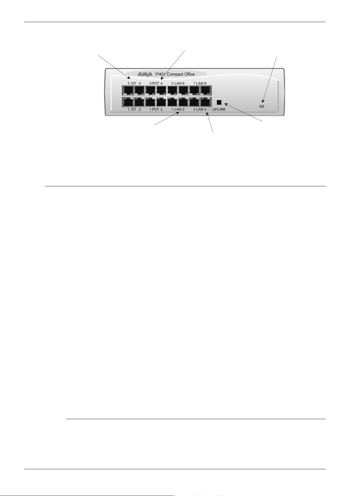
IP401 Compact Office — Front View
DT Ports 1-4
Green LEDs — Terminal connected
Yellow LEDs – Status of ISDN/WAN links
Phone Ports 1 -4
(POTS)
Unit Status LED
Red = Alive but not initiated
Green = Running OK
Flashing Green — LAN OK and activ
Solid Green LED — LAN O
Yellow LED on – 100Mbps operatio
Yellow LED 0ff — 10Mbps operatio
Note: The IP Compact Office DT4 is shown above. The IP Compact Office DT2 does not
have the top row (labeled 3 DT 4, 3 POT 4, 5 LAN 6 and 7 LAN 8) of RJ45 ports
fitted.
Port connections
• DT Ports: DT ports are used for connection to Avaya 2000 series telephones (see
page 5) and support either A-Law or µ-Law PCM encoding (default A-Law). Using DT
Line Cords (see page 68) and standard structured wiring, these RJ45 ports can be
extended to the required telephone location. In addition, converters can be used to
provide BT New Plan sockets (431A/631A) if required (see page 77). When telephones
are equipped with line cords that terminate in RJ11 plugs, then pin-to-pin RJ11/RJ45
adapters should be used.
• Plain Ordinary Telephone (POT) Ports: These ports are used for connection to
standard analog telephones, fax machines and modems. These ports must not be
used for connection to trunks. Using standard structured wiring, these RJ45 ports can
be extended to the required telephone location. Converters can be used to provide BT
New Plan sockets (431A/631A) if required (see page 77). When telephones are
equipped with line cords that terminate in RJ11 plugs, then pin-to-pin RJ11/RJ45
adapters should be used.
• LAN Ports: The auto-negotiating 10/100 BaseT LAN hub ports are used for PC and
server connectivity. They can also be used to connect to IP telephones (Avaya 4600 IP
series).
LAN ports allow information relating to incoming and outgoing telephone calls to be
forwarded to PC based applications. They also provide access to the router
functionality/configuration of the IP401 Compact Office platform for both data and Voice
over IP (VoIP) calls. The auto-negotiating 10/100 BaseT LAN hub ports support a
single MAC address only (printed on base of unit).
Where more than eight LAN connections are required, the fourth LAN port can be used
for cascading to other hubs. The Cascade pushbutton to the right of this port is used to
set the mode. When the Cascade switch is in the out position the port can be
connected to another hub without the need for a crossover cable, i.e. the port is an MDI
type port. When the Cascade switch is in the in position the port can be connected
directly to a PC.
LAN Ports 1-
LAN Port 4
(Cascade Port)
Cascade Switch
(for Port 4)
Cables
IP401 Compact Office 2 is supplied with one red CAT5E cable. The Compact Office 4 is
supplied with two red CAT5E cables. For Port Pinouts and Cables, refer to pages 63 and
67 respectively.
IP Office Installation Manual IP401 Compact Office Platform — Page 7
40DHB0002USCL – Issue 9 (28th October 2003) IP401 Compact Office — Front View

Page 8 — IP401 Compact Office — Rear View IP401 Compact Office Platform
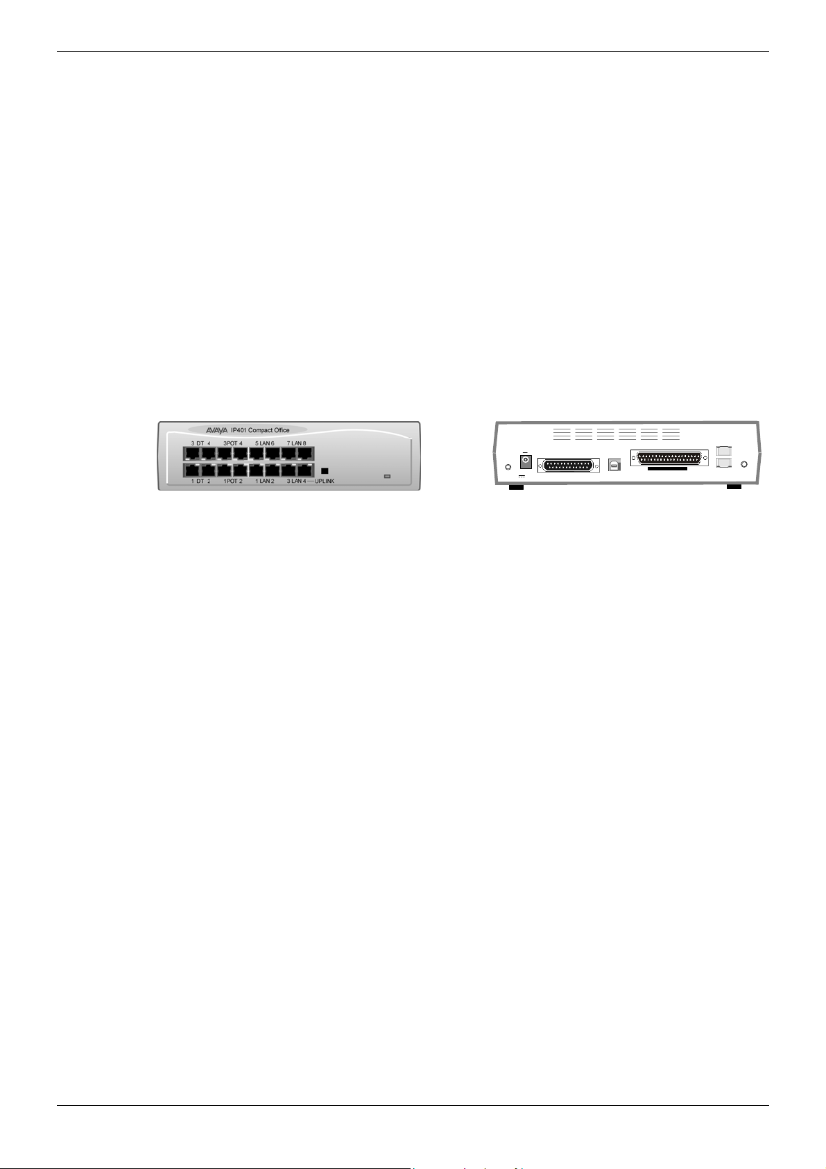
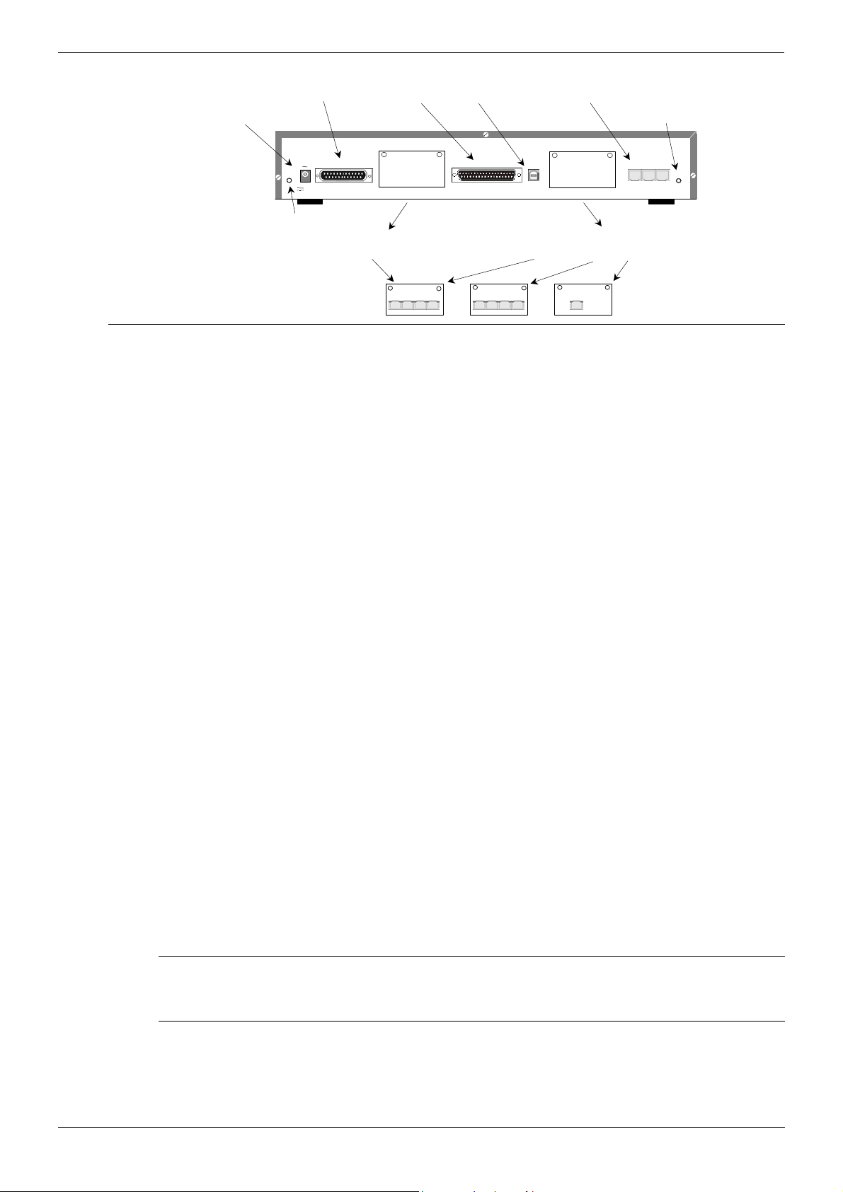
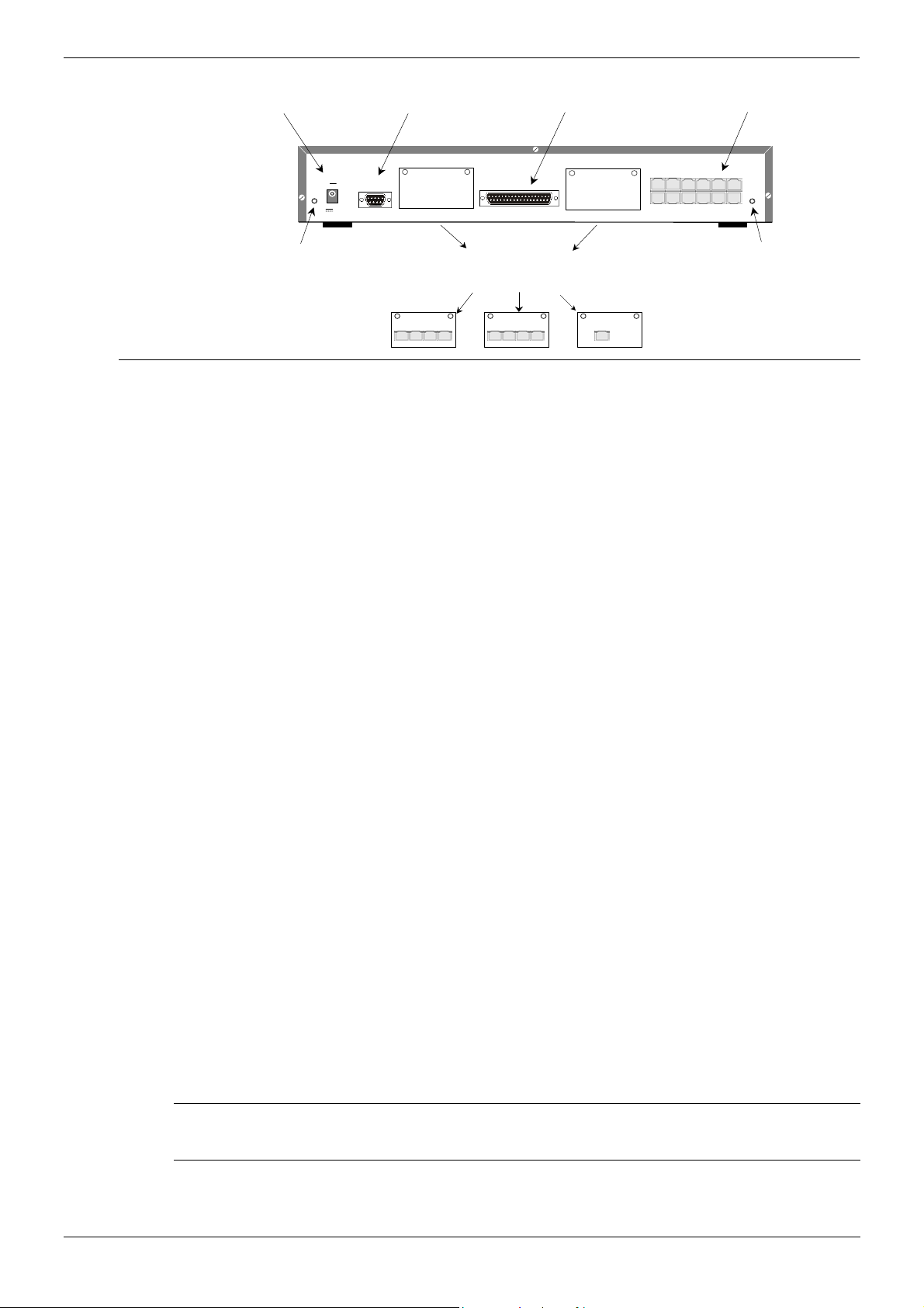
IP401 Compact Office — Rear View
DC Power I/P Socket
External O/P Socket
Notes: 1. The IP401 Compact Office 4 is shown above; the WAN port is optional.
2. On an IP401 Compact Office 2, the WAN port is optional and BRI 1 is not
fitted. (See pages 28 and 45 for upgrade kits and expansion instructions
respectively).
3. The IP401 Compact Office can be wall mounted (see page 44).
Port connections
• External O/P Socket: Allows externally powered circuits to be controlled via a single
3.5mm stereo jack socket.
• DC Power I/P Socket: Socket for the external 24V DC unregulated power supply
(supplied with kit).
• DTE Port: A 25-way D-type socket. Used for connection to PCs, servers and EFTPOS
terminals.
• BRI Ports: Two BRI trunk interface ports are fitted on an IP401 Compact Office 4 and
only one on an IP401 Compact Office 2; providing four and two trunks respectively.
See page 45 for expansion and page 28 for country specific variants.
• WAN Port: This port supports a single synchronous data connection, which can be
X.21, V.35 or V.24. The selection of the required interface is automatically determined
from the pin-out of the cable plugged into the ‘WAN’ port. This cable must be
connected before power is applied for auto detection to work. Connection to a Digital
Leased Circuit is made by connecting the WAN port on the rear of the unit to the
existing Network Terminating Unit (NTU) via the appropriate X.21, V.35 or V.24 cable.
See pages 74, 75 and 76 for cable details and page 66 for port details.
• USB Interface: This port may only be used by trained maintenance personnel using
static protection precautions. Used for connection to a PC or server, allowing it to
utilize the IP401 Office as a Terminal Adapter (TA).
• Audio I/P Socket: A single 3.5mm stereo or mono jack socket that enables input from
an external ‘Music-on-Hold’ source.
EXT
O/P
USB Interface Socket
DC I/P
— C +
24V DC
2A
DTE
DTE Port
Vents
USB
Slot for VME Card
WAN
WAN Port
BRI 1
BRI 2
Audio I/P Socket
BRI Ports
AUDI O
Port Pinouts and Cables
For Port Pinouts and Cables, refer to pages 63 and 67 respectively.
Page 8 — IP401 Compact Office Platform IP Office Installation Manual
IP401 Compact Office — Rear View 40DHB0002USCL – Issue 9 (28th October 2003)
IP401 Compact Office Platform IP401 Compact Office — Rear View — Page 9
Typical Configuration
Scenario:
A customer requiring a voice and data solution for a warehousing facility remote from a
regional office. Three administrators and two pickers staff the warehouse.
This configuration provides support for four Avaya 2000 series digital telephones, one for
each of the administrators, leaving a spare port for future growth. Up to four analog
telephones (POTS), two of which support a DECT wireless solution to allow the pickers
freedom of movement, with one of the remaining ports being used for a fax machine.
The eight port 10/100M Hub allows the local PCs and Printers to be networked.
Connectivity for all voice and data traffic between the Warehouse and the regional office is
carried over the optional IP401 WAN interface using Voice over IP and standards based
compression (through the optional IP400 VCM 5 media card). Two ISDN ports allow up to
four simultaneous calls to the public network.
Kit List
IP401 Compact Office DT4
IP401 Compact Office WAN Expansion
IP400 Office Voice Compression Module 5
2 x 2030 Display Terminals
WAN
DC I/P
— C +
EXT
O/P
24V DC
2A
DTE
USB
BRI 1
AUDIO
BRI 2
IP Office Installation Manual IP401 Compact Office Platform — Page 9
40DHB0002USCL – Issue 9 (28th October 2003) IP401 Compact Office — Rear View

Page 10 — General IP403 Office Platform
IP403 Office Platform
General
The IP403 Office base unit supports up to eight digital and two analog telephones. This
can be expanded, by use of 3 additional extension modules, to a max. of 100 extensions.
Two variants are available and are equipped as follows:
• DT ports — support Avaya 2000 series telephones.
• DS ports — support Avaya 6400, 2420 series and/or Avaya 4400 series telephones.
Both ports can be set for either µ-Law or A-Law PCM encoding. At default DT ports are
set to A-Law and DS ports are set to µ-Law. However, these can be switched in software
(refer to the Administration Manager Manual for details).
Connection to trunks is via one* of the following integral interface modules:-
— Single PRI E1 (30 trunks) or Single PRI T1 (23B+1D or 24B trunks — USA only) or
— Quad BRI (8 trunks) or Analog 4 (loop start trunks).
*If Analog 4 modules are used, a second module can be fitted in Slot A.
See page 40 for installation and page 28 for country specific variants.
An eight port auto-negotiating 10/100 BaseT LAN hub provides access to networks and/or
up to eight IP telephones. (Where IP telephones are to be used, the hub should be
connected to a suitable LAN switch with QoS capabilities.)
Expansion Modules
Optional Expansion Modules (see page 23) allow the IP403 Office to be expanded to
100 extensions. These modules (with the exception of the WAN3 – see below) are
connected via the Expansion Port sockets that are located on the back of each unit. Up to
3, in any combination, of the following Expansion Modules can be supported by the
IP403 Office base unit.
• IP400 Digital Terminal 16/30 or Digital Station 16/30: Two variants of both (16 or 30
extensions) for digital telephones (see page 23). Hence, if all 3 extension modules are
IP400 Digital Terminal/Station 30s, then the maximum of 100 extensions will consist of
90 digital extensions, plus the base unit’s 2 analog extensions and 8 digital extensions.
• IP400 Phone 8/16/30: Three variants (8, 16 or 30 extensions) for analog telephones
(see page 24). Hence, if all 3 extension modules are IP400 Phone 30s, then the
maximum of 100 extensions will consist of 90 analog extensions, plus the base unit’s 2
analog extensions and 8 digital extensions.
• IP400 So8: An S-bus module that provides 8 Basic Rate ISDN interfaces
(see page 25).
• IP400 WAN3: Provides support for a further 3 digital leased line (WAN) connections
(see page 26). These expansion modules are connected to the IP403 Office unit via
one of the LAN Ports located on the front of each unit.
• IP400 Analog Trunk 16: Provides support for up to 16 Loop Start or Ground Start
analog trunks (see page 27). Two power fail sockets are also provided.
Integral Modules (Optional)
In addition the IP403 Office can be fitted with either or both of the following optional
Integral Modules (see pages 41 and 42):
• Voice Compression Module (VCM): Supports VoIP applications including trunking
and support for IP telephones. Available in 5,10 and 20 channel variants.
• Dual Modem Module: Allows termination of two simultaneous analog modem calls up
to and including 56kbps.
Page 10 — IP403 Office Platform IP Office Installation Manual
General 40DHB0002USCL – Issue 9 (28th October 2003)

IP403 Office Platform IP403 Office — Front View — Page 11
IP403 Office — Front View
ellow LEDs
LEDs 1-3 = Expansion Ports 1-3 status
LEDs 4-7 = ISDN 1-4 status
LED 8 = WAN status
Green LEDs
Terminal connected
DT or DS Ports 1-8
Port connections
• DT/DS Ports
— DT ports are for connection to Avaya 2000 series telephones (see page 5).
— DS ports are for connection to Avaya 4400, 2420 and/or 6400 series telephones
(see page 5).
At default DT ports are set to A-Law PCM encoding and DS ports to either A-Law or µ-
Law PCM encoding (see page 28). However, both ports can be switched in software refer to the Administration Manager Manual for details).
Using DT Line Cords (see page 68) and standard structured wiring, these RJ45 ports
can be extended to the required telephone location. In addition, converters can be
used to provide BT New Plan sockets (431A/631A) if required (see page 77). When
telephones are equipped with line cords that terminate in RJ11 plugs, then pin-to-pin
RJ11/RJ45 adapters should be used.
• Plain Ordinary Telephone (POTS) Ports: These two ports are used for connection to
standard analog telephones, fax machines and modems. They must not be connect to
trunks. Using standard structured wiring, these RJ45 ports can be extended to the
required telephone location. Converters can be used to provide BT New Plan sockets
(431A/631A) if required (see page 77). When devices are equipped with line cords that
terminate in RJ11 plugs, then pin-to-pin RJ11/RJ45 adapters should be used.
• LAN Ports: The eight auto-negotiating 10/100 BaseT LAN hub ports are used for PC
and server connectivity. They can also be used to connect to the optional IP400 WAN3
Expansion Module (see page 26) and IP telephones. LAN ports allow information
relating to incoming and outgoing telephone calls to be forwarded to PC based
applications. They also provide access to the router functionality/configuration of the
IP403 Office platform for both data and Voice over IP (VoIP) calls. (Where IP telephony
is required, a suitable switch LAN switch with QoS capabilities.) This eight port autonegotiating 10/100 BaseT LAN hub has a single MAC address (printed on the base of
the unit).
Where more than eight LAN connections are required, the eighth LAN port can be used
for cascading to other hubs. The Cascade pushbutton to the right of this port is used to
set the mode. When the Cascade switch is in the out position the port can be
connected to another hub without the need for a crossover cable, i.e. the port is an MDI
type port. When the Cascade switch is in the in position the port can be connected
directly to a PC.
Unit Status LED
Red = Alive but not initiated
Green = Running OK
Analog Telephone Ports 1& 2
POTs
ellow LED
LAN Collision
Green LED
Solid Green LED — LAN OK
Flashing Green — LAN OK and active
Port 8
LAN Ports 1-8
Cascade port)
ellow LED
On — 100Mbps operation
0ff — 10Mbps operation
Cascade Switch
For port eigh
Cables
IP403 Office DT PRI 30 E1 & DS PRI 24 T1 are supplied with one red CAT5E cable.
IP403 Office DT BRI 8 & DS Analog 4 are supplied with four red CAT5E cables. For Port
Pinouts and Cables, refer to pages 63 and 67 respectively.
IP Office Installation Manual IP403 Office Platform — Page 11
40DHB0002USCL – Issue 9 (28th October 2003) IP403 Office — Front View
Page 12 — IP403 Office — Rear View IP403 Office Platform
IP403 Office — Rear View
DC Power I/P Socket
EXT
O/P
24V DC
2A
External O/P Socket
DTE Port
DC I/P
— C +
Slot A is normally blank, but can
contain an ANALOG Trunk Module
WAN Port
DTE
Slot A
USB Interface Socket
WAN
Expansion Ports 1-3
Audio I/P Socket
EXPANSION
1 2 3
Slot B
Slot B can contain either an ANALOG
or BRI or PRI Trunk Module
AUDIO
Port connections
• External O/P Socket: Two relay ports that allow externally powered circuits to be
controlled via a single 3.5mm stereo jack socket.
• DC Power I/P Socket: Socket for the external 24V DC unregulated power supply
(supplied with equipment).
• DTE Port: A 25-way D-type socket. Used for connection to PCs, servers and EFTPOS
devices or terminals.
• BRI/PRI/ANALOG Ports: The trunk interface modules are fitted into either Slot A or
Slot B as follows:
Slot A Quad Analog: 4 trunks (see page 35 for grounding)
Slot B Quad Analog: 4 trunks (see page 35 for grounding)
PRI E1/PRI E1-R2: 30 trunks
PRI T1: 24B trunks or 23B+1D trunks (see page 35 for grounding)
Quad BRI: 8 trunks.
PRI T1 trunks support both ISDN and Analog emulation. The default setting is 23B+1D
and is switchable in the installation software to provide 24B trunks.
See page 40 for installation, page 29 for country specific variants and page 35 for
grounding.
• WAN Port: This port supports a single synchronous data connection, which can be
X.21, V.35 or V.24. The selection of the required interface is automatically determined
from the pin-out of the cable plugged into the ‘WAN’ port. This cable must be
connected before power is applied for auto detection to work. Connection to a Digital
Leased Circuit is made by connecting the WAN port on the rear of the unit to the
existing Network Terminating Unit (NTU) via the appropriate X.21, V.35 or V.24 cable.
See pages 74, 75 and 76 for cable details and page 66 for port details. These
interfaces are identical to those on the WAN3 Extension Module (see page 26).
• USB Interface: Used for connection to a PC or server, allowing it to utilize the IP403
Office as a Terminal Adapter (TA).
• Expansion Ports 1-3: Used to provide access to the optional Expansion Modules
(see page 23) which allow the IP403 Office to be expanded to 100 extensions
(see page 10).
• Audio I/P Socket: A single 3.5mm stereo or mono jack socket that enables input from
an external ‘Music-on-Hold’ source.
ANALOG TRUNK
1 2 3 4
BRI
1 2 3 4
PRI
Port Pinouts and Cables
• For Port Pinouts and Cables, refer to pages 63 and 67 respectively.
Functional Earth
For Functional Earth connections see page 35.
Page 12 — IP403 Office Platform IP Office Installation Manual
IP403 Office — Rear View 40DHB0002USCL – Issue 9 (28th October 2003)
IP403 Office Platform IP403 Office — Rear View — Page 13
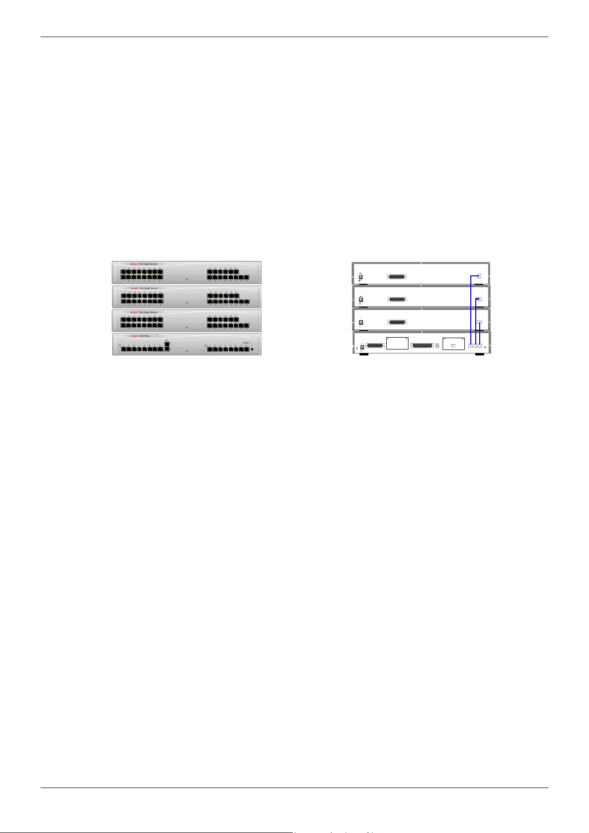
Typical Configuration
Scenario:
A customer with sophisticated telephony requirements, needing 30 exchange lines and 80
Display Terminals.
This configuration provides support for 98 Avaya 20 series digital telephones (18 spare for
growth) and a single Primary Rate ISDN connection. If growth beyond 18 users or
additional line capacity were anticipated, the IP406 Office would be considered more
appropriate. Typically, a business of this size would have a data network built using LAN
switches such as the Avaya Cajun range. The IP403 Compact Office would be connected
to the data network through its integral 8 port Hub, providing all users access to the
Internet and IP Office productivity applications.
Kit List
IP403 Office DT PRI 30 E1
3 x IP400 Digital Terminal Module 30
80 x 2030 Display Terminals
DC I/P
— C +
24V DC
2A
DC I/P
— C +
24V DC
2A
DC I/P
— C +
24V DC
2A
DC I/P
— C +
EXT
O/P
24V DC
2A
DTE
DTE
DTE
DTE
WAN
Slot A
PRI
Slot B
EXPANSION
EXPANSION
EXPANSION
EXPANSION
1 2 3
AUDIO
IP Office Installation Manual IP403 Office Platform — Page 13
40DHB0002USCL – Issue 9 (28th October 2003) IP403 Office — Rear View

Page 14 — General IP406 Office Platform
IP406 Office Platform
General
The IP406 Office base unit supports up to 180 extensions by using up to 6 Expansion
modules. Connection to trunks is via any two of the following integral interface modules as
follows:-
— Single PRI E1/PRI E1-R2 (30 trunks) or
— Single PRI T1 (23B+1D or 24B trunks — USA only) or
— Quad BRI (8 trunks) or
— Analog 4 (loop start).
See page 40 for installation and page 28 for country specific variants.
An eight port auto-negotiating 10/100 BaseT LAN hub provides access to networks and/or
up to eight IP telephones.
(Where IP telephones are to be used a suitable LAN switch with QoS capabilities, should
be used).
Expansion Modules
Optional Expansion Modules (see page 23) allow the IP406 Office to be expanded to
180 extensions. These modules (with the exception of the WAN3 – see below) are
connected via the Expansion Port sockets that are located on the back of each unit.
Up to six, in any combination, of the following Expansion Modules can be supported by
the IP406 Office base unit.
• IP400 Digital Terminal 16/30 or Digital Station 16/30: Two variants of both (16 or 30
extensions) for digital telephones (see page 23).
Hence, six IP400 Digital Terminal/Station 30s will allow a maximum of 180 digital
extensions.
• IP400 Phone 8/16/30: Three variants (8, 16 or 30 extensions) for analog telephones
(see page 24).
Hence, six IP400 Phone 30s will allow a maximum of 180 analog extensions.
• IP400 So8: An S-bus module that provides 8 Basic rate ISDN interfaces
(see page 25).
• IP400 WAN3: Provides support for a further 3 digital leased line (WAN) connections
(see page 26). These expansion modules are connected to the IP403 Office unit via
one of the LAN Ports located on the front of each unit.
• IP400 Analog Trunk 16: Provides support for up to 16 Loop Start or Ground Start
analog trunks (see page 27). Two power fail sockets are also provided.
Integral Modules (Optional)
In addition the IP406 Office can be fitted with either or both of the following optional
Integral Modules (see pages 41 and 42):
• Voice Compression Module (VCM)
Supports VoIP applications including trunking and support for IP telephones. Available
in 5, 10 and 20 channel variants.
• Dual Modem Module
Allows termination of two simultaneous analog modem calls up to and including
56kbps.
Page 14 — IP406 Office Platform IP Office Installation Manual
General 40DHB0002USCL – Issue 9 (28th October 2003)
IP406 Office Platform IP406 Office — Front View — Page 15
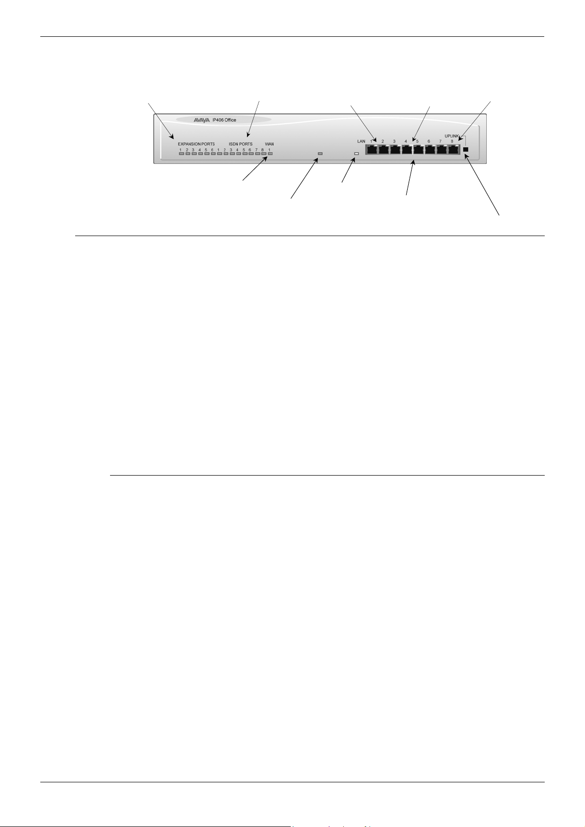
IP406 Office — Front View
Expansion Ports 1
Green Status LEDs
Port connections
• LAN Ports
The eight auto-negotiating 10/100 BaseT LAN hub ports are used for PC and server
connectivity. They can also be used to connect to the optional IP400 WAN3 Expansion
Module (see page 26) and IP telephones.
LAN ports allow information relating to incoming and outgoing telephone calls to be
forwarded to PC based applications. They also provide access to the router
functionality/configuration of the IP406 Office platform for both data and Voice over IP
(VoIP) calls. (Where IP telephony is required, the hub must be connected to a suitable
LAN switch with QoS capabilities.) This eight port auto-negotiating 10/100 BaseT LAN
hub supports a single MAC address only (printed on the base of the module).
Where more than eight LAN connections are required, the eighth LAN port can be used
for cascading to other hubs. The Cascade pushbutton to the right of this port is used to
set the mode. When the Cascade switch is in the out position the port can be
connected to another hub without the need for a crossover cable, i.e. the port is an MDI
type port. When the Cascade switch is in the in position the port can be connected
directly to a PC.
ISDN Port s 1
Green Status LEDs
WAN Por
Green Status LED
Green LED
Solid Green LED — LAN OK
Flashing Green — LAN OK and active
Unit Statu
Red = Alive but not ini tiated
Green = Running OK
ellow LED
LAN Collision
ellow LED
On — 100Mbps operation
0ff — 10Mbps operation
LAN Ports 1-8
Port
(Cascade Port
Cascade Switch for Port
Cables
IP406 Office PRI 30 E1 & PRI 24 T1 are supplied with one red CAT5E cable. IP406 Office
Analog 4 is supplied with four red CAT5E cables. IP406 Office BRI 16 is supplied with
eight red CAT5E cables. For Port Pinouts and Cables, refer to pages 63 and 67
respectively.
IP Office Installation Manual IP406 Office Platform — Page 15
40DHB0002USCL – Issue 9 (28th October 2003) IP406 Office — Front View
Page 16 — IP406 Office — Rear View IP406 Office Platform
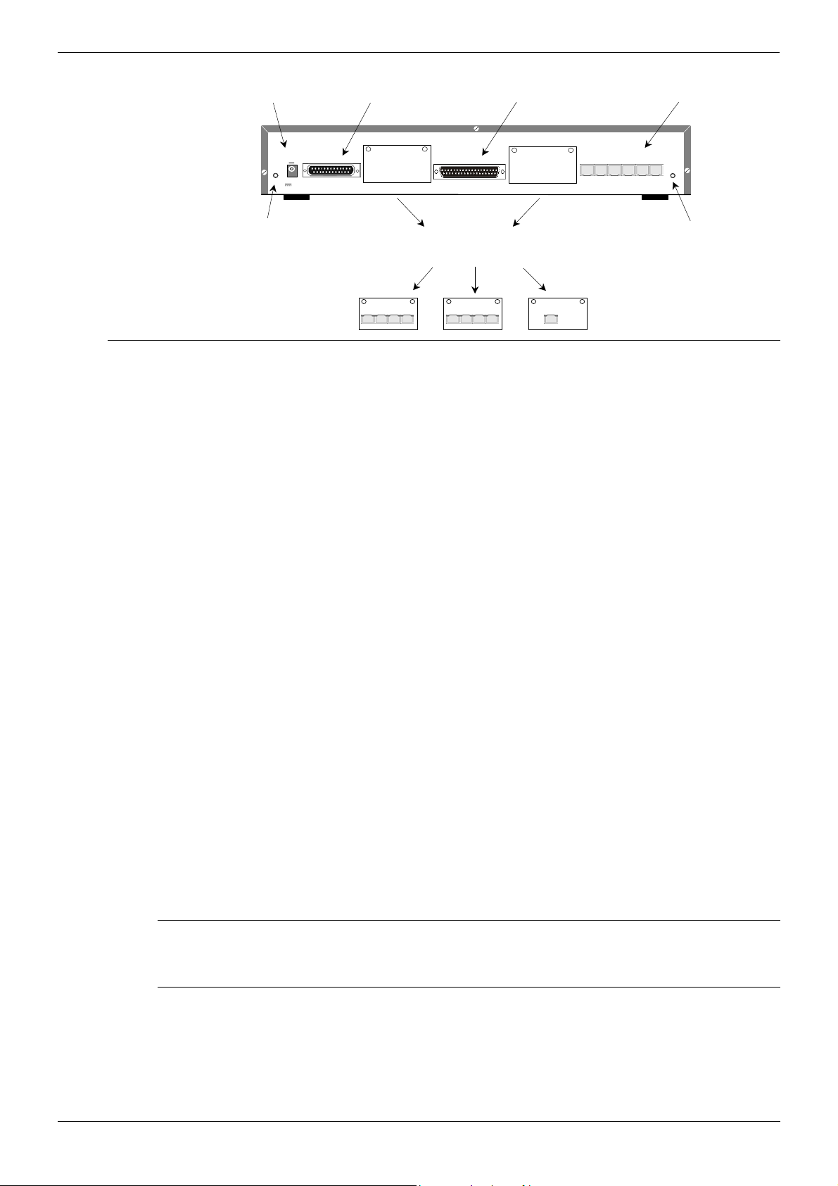
IP406 Office — Rear View
DC Power I/P Socket
DTE Port
WAN Port
Expansion Ports 1-6
External O/P Socket
Port connections
• External O/P Socket: Two relay ports that allow externally powered circuits to be
controlled via a single 3.5mm stereo jack socket.
• DC Power I/P Socket: Socket for the external 24V DC unregulated power supply
(supplied with kit).
• DTE Port: A 25-way D-type socket. Used for connection to PCs, servers and EFTPOS
terminals.
• BRI/PRI/ALOG Ports: The trunk interface modules are fitted into either Slots A or B
and can consist of any combination of:
— Quad Analog — 4 trunks (see page 35 for grounding)
— PRI E1/PRI E1-R2: 30 trunks
— PRI T1: 24B trunks or 23B+1D trunks (see page 35 for grounding)
— Quad BRI: 8 trunks.
PRI T1 trunks support both ISDN and Analog emulation. The default setting is 23B+1D
and is switchable in the installation software to provide 24B trunks.
See page 40 for installation, page 29 for country specific variants and page 35 for
grounding.
• WAN Port: This port supports a single synchronous data connection, which can be
X.21, V.35 or V.24. The selection of the required interface is automatically determined
from the pin-out of the cable plugged into the ‘WAN’ port. This cable must be
connected before power is applied for auto detection to work. Connection to a Digital
Leased Circuit is made by connecting the WAN port on the rear of the unit to the
existing Network Terminating Unit (NTU) via the appropriate X.21, V.35 or V.24 cable.
See pages 74, 75 and 76 for cable details and page 66 for port details. These
interfaces are identical to those on the WAN3 Extension Module (see page 26).
• Expansion Ports 1-6: Used to provide access to the optional Expansion Modules
(see page 23) which allow the IP406 Office to be expanded to 180 extensions (see
page 14).
• Audio I/P Socket: A single 3.5mm stereo or mono jack socket that enables input from
an external ‘Music-on-Hold’ source.
DC I/P
DTE
— C +
EXT
O/P
24V DC
2A
Slot A
Slots A and B can contain any combination of
ANALOG or BRI or PRI Trunk Modules
(Slot B must be used first)
NALOG TRUNK
1 2 3 4
WAN
BRI
1 2 3 4
Slot B
PRI
EXPANSION
1 2 3 4 5 6
AUDIO
udio I/P Socket
Port Pinouts and Cables
• For Port Pinouts and Cables, refer to pages 63 and 67 respectively.
Functional Earth
For Functional Earth connections see page 35.
Page 16 — IP406 Office Platform IP Office Installation Manual
IP406 Office — Rear View 40DHB0002USCL – Issue 9 (28th October 2003)
IP406 Office Platform IP406 Office — Rear View — Page 17
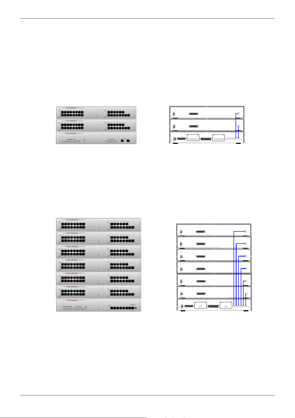
Typical Configurations
Scenario 1:
A business requiring 60 analog Telephones and 8 Basic Rate ISDN lines (16 channels).
The IP406 Office BRI 16 with two IP400 Office Phone 30 modules provides the required
line and extension capacity. Through the use of PhoneManager Lite the functionality
provided by the Analog Telephones is greatly enhanced. Expansion capability for an
additional 4 Modules allows the system to be expanded to a full 180 extensions.
Additional lines can be added by replacing one of the BRI interfaces for a Primary rate.
Kit List
IP406 Office BRI 16
2 x IP400 Office Phone Module 30
DC I/P
— C +
24V DC
2A
DC I/P
— C +
24V DC
2A
DC I/P
DTE WAN
— C +
EXT
O/P
24V DC
2A
DTE
DTE
BRI
1 2 3 4
Slot A
BRI
1 2 3 4
Slot B
EXPANSION
1 2 3 4 5 6
EXPANSION
EXPANSION
A UDIO
Scenario 2:
A business requiring 180 analog Telephones and 60 lines.
The configuration illustrates a fully configured IP406 Office providing 180 extensions and
60 trunks. Factory shipped with a single PRI the system is fitted with an extra trunk card in
its spare slot to provide the additional 30 lines.
Kit List
IP406 Office PRI 30 E1 fitted with an additional IP400 IP PRI E1 trunk card
6 x IP400 Office Phone Module 30
DC I/P
— C +
24V DC
2A
DC I/P
— C +
24V DC
2A
DC I/P
— C +
24V DC
2A
DC I/P
— C +
24V DC
2A
DC I/P
— C +
24V DC
2A
DC I/P
— C +
24V DC
2A
DC I/P
DTE WAN
— C +
EXT
O/P
24V DC
2A
DTE
DTE
DTE
DTE
DTE
DTE
PRI
Slot A
PRI
Slot B
EXPANSION
2 4 6 8 10 12
1 3 5 7 9 11
EXPANSION
EXPANSION
EXPANSION
EXPANSION
EXPANSION
EXPANSION
AUDIO
IP Office Installation Manual IP406 Office Platform — Page 17
40DHB0002USCL – Issue 9 (28th October 2003) IP406 Office — Rear View

Page 18 — General IP412 Office Platform
IP412 Office Platform
General
The IP412 Office base unit supports up to 360 extensions by using up to12 Expansion
modules. Connection to trunks is via a combination of any of the following integral
interface modules :-
— Single or Dual PRI E1/PRIE1-R2 (30 or 60 trunks respectively)
— Single or Dual PRI T1 (24 or 48 trunks respectively — USA only)
— Quad BRI (8 trunks)
— Analog 4 (4 loop start trunks)
See page 40 for installation and page 28 for country specific variants.
Dual independent auto-negotiating 10/100 BaseT Ethernet ports provide segmented
access (allows a firewall break to be used) to the LAN.
(Where IP telephones are to be used a suitable LAN switch with QoS capabilities, must be
used.)
Expansion Modules
Optional Expansion Modules (see page 23) allow the IP412 Office to be expanded to a
maximum of 360 digital or analog extensions. The Expansion Modules (with the exception
of the WAN3 – see below) are connected via the Expansion Port sockets that are located
on the back of each unit.
Up to twelve, in any combination, of the following Expansion Modules can be supported
by the IP412 Office base unit provided that the maximum number of extensions does not
exceed 360.
• IP400 Digital Terminal 16/30 or Digital Station 16/30: Two variants of both (for 16 or
30 extensions) for digital telephones (see page 23). Hence, twelve IP400 Digital
Terminal/Station modules can be fitted to allow a maximum of 360 digital extensions.
• IP400 Phone 8/16/30: Three variants (for 8, 16 or 30 extensions) for analog
telephones (see page 24). Hence, twelve IP400 Phone modules can be fitted to allow a
maximum of 360 analog extensions.
• IP400 So8: An S-bus module that provides 8 Basic rate ISDN interfaces
(see page 25).
• IP400 WAN3: Provides support for a further 3 digital leased line (WAN) connections
(see page 26). These expansion modules are connected to the IP403 Office unit via
one of the LAN Ports located on the front of each unit.
• IP400 Analog Trunk 16: Provides support for up to 16 Loop Start or Ground Start
analog trunks (see page 27). Two power fail sockets are also provided.
Integral Modules (Optional)
In addition the IP412 Office can be fitted with either or both of the following optional
Integral Modules (see pages 41 and 42):
• Voice Compression Module (VCM)
Provides VoIP applications including trunking and support for IP telephones. Available
in 5, 10, 20 and 30 channel variants. The IP412 Office can have two VCMs (of any
type).
• Dual Modem Module
Allows termination of two simultaneous analog modem calls at speeds up to and
including 56kbps (V.90).
Page 18 — IP412 Office Platform IP Office Installation Manual
General 40DHB0002USCL – Issue 9 (28th October 2003)

IP412 Office Platform IP412 Office — Front View — Page 19
IP412 Office — Front View
Expansion Ports 1-12
Green Stat us LEDS
Port connections
• LAN Ports: The segmented dual independent auto-negotiating 10/100 BaseT Ethernet
ports are used for PC and server connectivity. They can also be used to connect to the
optional IP400 WAN3 Expansion Module (see page 26) and IP telephones.
Information relating to incoming and outgoing telephone calls can be forwarded to PC
based applications via these ports. These segmented Ethernet ports support separate
IP and MAC addresses and hence a Firewall break may be implemented. They also
provide access to the router functionality/configuration of the IP412 Office platform for
both data and Voice over IP (VoIP) calls. (Where IP telephony is required, a suitable
switch LAN switch with QoS capabilities.)
Unit Status LED
Red = Alive but not ini ti ated
Green = Running OK
WAN Port
Green Stat us LED
LAN Ports 1-
Trunk Ports 1-8
Green Stat us LEDS
Cables
IP412 Office DT PRI 30 E1 & DS PRI 24 T1 are supplied with one red CAT5E cable.
IP412 Office DT PRI60 E1 & PRI48 T1 are supplied with two red CAT5E cables. For Port
Pinouts and Cables, refer to pages 63 and 67 respectively.
IP Office Installation Manual IP412 Office Platform — Page 19
40DHB0002USCL – Issue 9 (28th October 2003) IP412 Office — Front View
Page 20 — IP412 Office — Rear View IP412 Office Platform
IP412 Office — Rear View
DC Power I/P Socket
EXT
O/P
24V DC
2A
DC I/P
— C +
DTE
DTE Port
Slot A
WAN
WAN Port
Slot B
Expansion Ports 1-12
EXPANSION
2 4 6 8 10 12
1 3 5 7 9 11
AUDIO
External O/P Socket
Port connections
• External O/P Socket
Two relay ports that allow externally powered circuits to be controlled via a single
3.5mm stereo jack socket.
• DC Power I/P Socket
Socket for the external 24V DC unregulated power supply (supplied with kit).
• DTE Port
A 9-way D-type socket. Used for connection to PCs, servers and EFTPOS terminals.
• BRI/PRI/ALOG Ports
The trunk interface modules are fitted into either Slots A or B as follows:
Slot A — Quad Analog: 4 trunks (see page 35 for grounding)
— Quad BRI: 8 trunks
— Single or Dual PRI E1/E1-R2: 30 or 60 trunks respectively
— Single or Dual PRI T1: 24B/ 23B+1D or 48B/46B+2D trunks respectively
(see page 35 for grounding).
Slot B — Single or Dual PRI E1/E1-R2: 30 or 60 trunks respectively
— Single or Dual PRI T1: 24B/ 23B+1D or 48B/46B+2D trunks respectively
(see page 35 for grounding).
PRI T1trunks support both ISDN and Analog emulation. The default setting is 23B+1D
(46B+2D) and is switchable in the installation software to become a 24B (48B) trunk.
See page 40 for installation, page 29 for country specific variants and page 35 for
grounding.
• WAN Port: This port supports a single synchronous data connection, which can be
X.21, V.35 or V.24. The selection of the required interface is automatically determined
from the pin-out of the cable plugged into the WAN port. This cable must be connected
before power is applied for auto detection to work. Connection to a Digital Leased
Circuit is made by connecting the WAN port on the rear of the unit to the supplied
Network Terminating Unit (NTU) via the appropriate X.21/V.35 /V.24 cable. See pages
74, 75 and 76 for cable details and page 66 for port details. These interfaces are
identical to those on the WAN3 Extension Module (see page 26).
• Expansion Ports 1-12: Used to provide access to either:
— optional Expansion Modules which allow the IP412 Office to be expanded to 256
extensions (see page 18).
— additional ISDN or WAN interfaces.
• Audio I/P Socket: A single 3.5mm stereo or mono jack socket that enables input from
an external ‘Music-on-Hold’ source.
Slots A and B can contain any combination of
ANALOG or BRI or PRI Trunk Modul es
Slot B must be used fir st
ANALOG TRUNK
1 2 3 4
BRI
1 2 3 4
PRI
udio I/P Socket
Port Pinouts and Cables
• For Port Pinouts and Cables, refer to pages 63 and 67 respectively.
Functional Earth
For Functional Earth connections see page 35.
Page 20 — IP412 Office Platform IP Office Installation Manual
IP412 Office — Rear View 40DHB0002USCL – Issue 9 (28th October 2003)
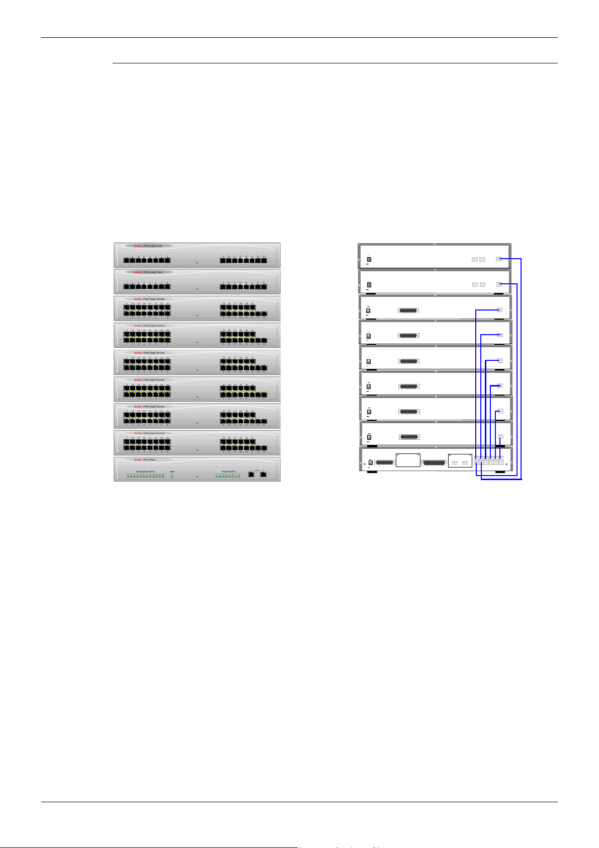
IP412 Office Platform IP412 Office — Rear View — Page 21
Typical Configurations
Scenario 1:
A business requiring 180 Display Telephones and 96 Digital lines with 20 Analog lines for
fall back purposes in the event of the T1 service failing.
The configuration illustrates a fully configured IP412 Office providing 180 extensions and
96 digital trunks (4 x T1) and two IP400 Office Analog Trunk 16 modules offering capacity
of up to 32 analog trunk lines. Factory shipped with a single Dual PRI T1 interface, the
system is fitted with an extra trunk card in its spare slot to provide the additional 48 lines.
Kit List
IP412 Office PRI 48 T1
6 X IP400 Office Digital Station 30 Module
2 x IP400 Office Analog Trunk 16
180 x Avaya 6412 Digital Terminals
DC I/P
— C +
24V DC
2A
DC I/P
— C +
24V DC
2A
DC I/P
— C +
24V DC
2A
DC I/P
— C +
24V DC
2A
DC I/P
— C +
24V DC
2A
DC I/P
— C +
24V DC
2A
DC I/P
— C +
24V DC
2A
DC I/P
— C +
24V DC
2A
DC I/P
— C +
EXT
O/P
24V DC
2A
DTE
DTE
DTE
DTE
DTE
DTE
DTE WAN
Slot A
PRI PRI
Slot B
EXPANSION
PF2
PF1
PF2
PF1
EXPANSION
2 4 6 8 10 12
1 3 5 7 9 11
EXPANSION
EXPANSION
EXPANSION
EXPANSION
EXPANSION
EXPANSION
EXPANSION
AUDIO
IP Office Installation Manual IP412 Office Platform — Page 21
40DHB0002USCL – Issue 9 (28th October 2003) IP412 Office — Rear View
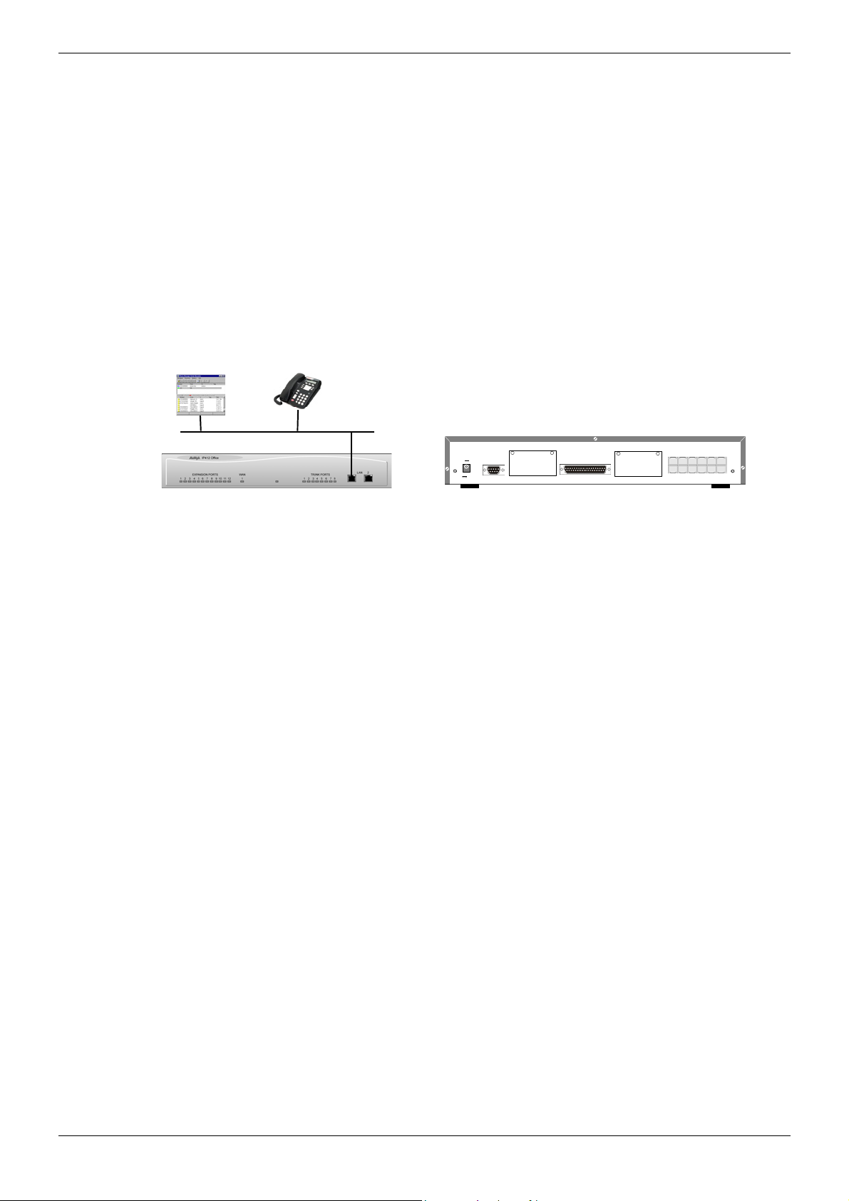
Page 22 — IP412 Office — Rear View IP412 Office Platform
Scenario 2:
A Business requiring 90 IP hardphones, 90 IP softphones and 60 lines.
This configuration illustrates an IP412 Office PRI 60 E1 fitted with two optional IP400
Office Voice Compression Module 20s. These two internally fitted cards allow up 40
simultaneous calls to external parties, as they are only used when an IP extension is
calling a non-IP telephone or line. If less ‘Gateway’ed calls are required, one of the 20
channel cards could be substituted for a smaller variant.
The IP Office softphone is ‘iPhoneManager Pro’ which requires two types of Licence Keys
which allow PhoneManager Lite, supplied as standard, to run as IP Extensions.
Kit List
IP412 Office PRI 60 E1fitted with two optional IP400 Voice Compression Module 20s,
90 x 4612 IP Hardphones
— IP400 PhoneManager Pro RFA
— IP400 iPhoneManager Pro RFA 50
— IP400 iPhoneManager Pro RFA 40 (50+40 = 90)
EXPANSION
Slot B
2 4 6 8 10 12
1 3 5 7 9 11
AUDIO
DC I/P
— C +
DTE
EXT
O/P
24V DC
2A
Slot A
WAN
Page 22 — IP412 Office Platform IP Office Installation Manual
IP412 Office — Rear View 40DHB0002USCL – Issue 9 (28th October 2003)
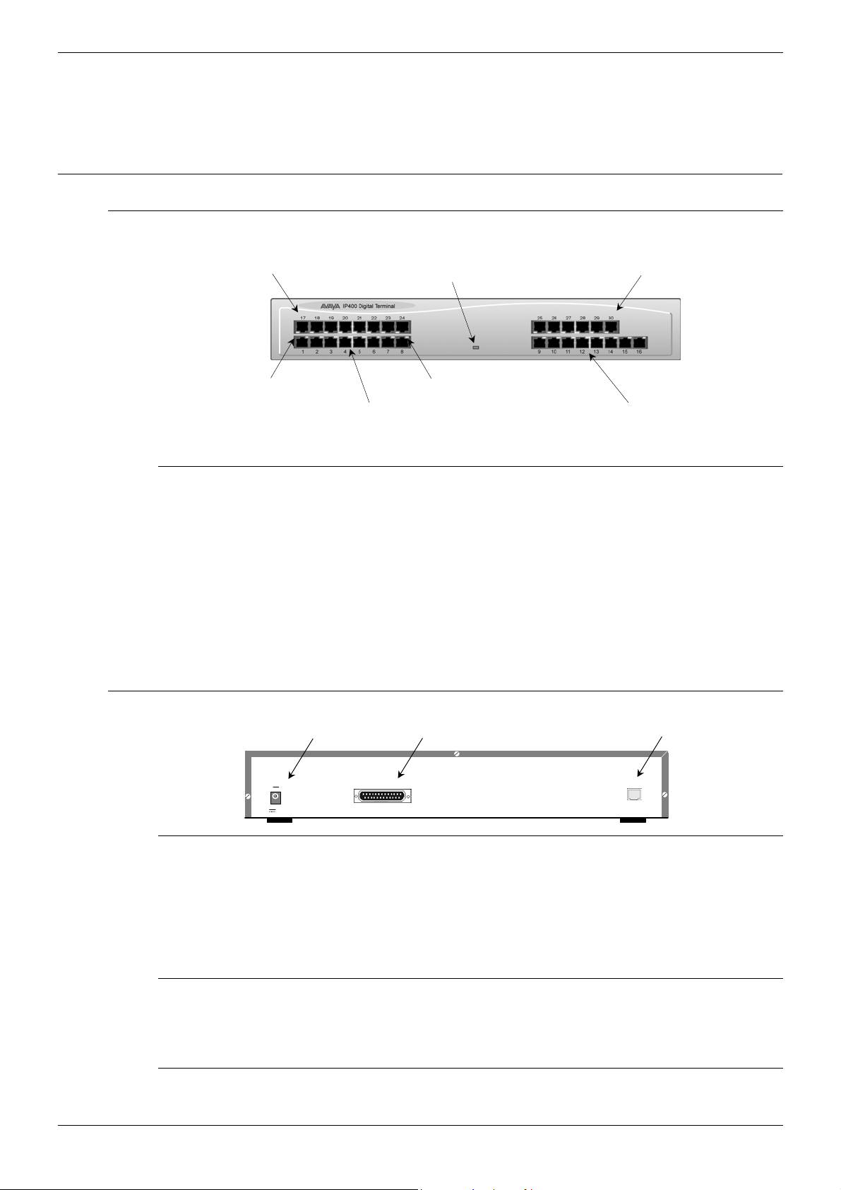
Expansion Modules IP400 Digital Terminal 16/30 — Page 23
Expansion Modules
Dependent upon configuration requirements, combinations of the following Expansion
Modules are used with IP Office platforms. With the exception of the WAN3 module (see
page 26), all of these Expansion Modules are connected to the Expansion Ports of an IP
Office platform using Expansion Interconnect Cables (see page 73).
IP400 Digital Terminal 16/30
Front View (30 Port version)
DT Ports 17 — 24
Unit Status LED
Red = Alive but not initi ated
Green = Running OK
DT Ports 25 — 30
Green LED
Connection OK
Note: The IP400 Digital Terminal 16 Expansion Module is only equipped with the
bottom row of ports (1-16).
Port connections
• DT ports are used for connection to Avaya 2000 series telephones (see page 5) and
support either A-Law or µ-Law PCM encoding. Both DT and DS ports can be set for
either µ-Law or A-Law PCM encoding. At default both types of port are set to µ-Law but
can be switched, in software, to A-Law (refer to the Administration Manager Manual for
details).
Using DT Line Cords (see page 68) and standard structured wiring, these RJ45 ports
can be extended to the required telephone location. In addition, converters can be
used to provide BT New Plan sockets (431A/631A) if required (see page 77). When
devices are equipped with line cords that terminate in RJ11 plugs, then RJ11/RJ45
adapters should be used.
Rear View (all versions)
DC Power I/P Socket
DC I/P
— C +
24V DC
2A
DT Ports 1 -8
DTE
DTE Port
ellow LED
(not used)
DT Ports 9 — 16
Expansion Port
EXPANSION
Port connections
• Expansion Port: Used to connect a Digital Terminal Expansion Module to the
Expansion Port of an IP Office platform.
• DC Power I/P Socket: Socket for the external 24V DC unregulated power supply
(supplied with kit).
• DTE Port: A 25-way D-type socket. Used for connection to PC (diagnostics only).
Cables
All IP400 Office Digital Terminal/Digital Station variants are supplied with one blue
Expansion Interconnect cable. For Port Pinouts and Cables, refer to pages 63 and 67
respectively.
Functional Earth
For Functional Earth connections see page 35.
IP Office Installation Manual Expansion Modules — Page 23
40DHB0002USCL – Issue 9 (28th October 2003) IP400 Digital Terminal 16/30
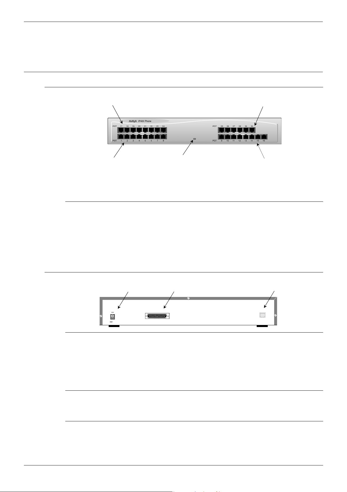
Page 24 — IP400 Digital Stations 16/30 Expansion Modules
IP400 Digital Stations 16/30
The IP400 Digital Station Expansion Module similar to the IP400 Digital Terminal
Expansion Module (see page 23) with the exception that the Ports are labeled DS not DT
and support Avaya 6400, 2420 or 4400 series telephones.
IP400 Phone 8/16/30
Front View (30 port version)
Phone Ports 17 — 24
Phone Ports 25 — 30
Phone Ports 1 — 8
Notes: The IP400 Phone 8 variant is only equipped with the bottom left row of ports.
The IP400 Phone 16 variant is only equipped with the bottom row of ports.
Port connections
• Plain Ordinary Telephone (POT) Ports: These ports are used for connection to
standard analog telephones, fax machines and modems. Using standard structured
wiring, these RJ45 ports can be extended to the required telephone location.
Converters can be used to provide BT New Plan sockets (431A/631A) if required (see
page 77). When devices are equipped with line cords that terminate in RJ11 plugs,
then RJ11/RJ45 adapters should be used.
• All analog telephones must conform to the port specification (see page 79).
Rear View (all versions)
DC Power I/P Socket
DC I/P
— C +
24V DC
2A
Unit Status LED
Red = Alive but not ini tiated
Green = Running OK
DTE
DTE Port
Phone Ports 9 — 16
Expansion Port
EXPANSION
Port connections
• Expansion Port: Used to connect a Phone Expansion Module to the Expansion Ports
of an IP Office platform.
• DC Power I/P Socket: Socket for the external 24V DC unregulated power supply
(supplied with kit).
• DTE Port: A 25-way D-type socket. Used for connection to PC (diagnostics only).
Cables
All IP400 Office Phone variants are supplied with one blue Expansion Interconnect cable.
For Port Pinouts and Cables, refer to pages 63 and 67 respectively.
Functional Earth
For Functional Earth connections see page 35.
Page 24 — Expansion Modules IP Office Installation Manual
IP400 Digital Stations 16/30 40DHB0002USCL – Issue 9 (28th October 2003)
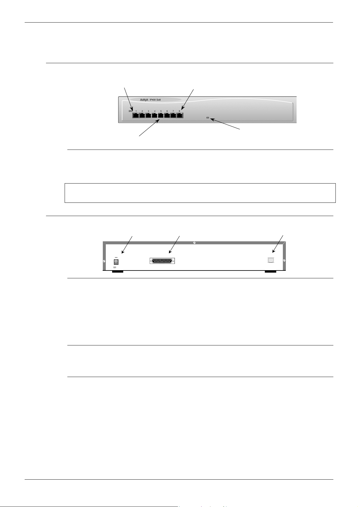
Expansion Modules IP400 So8 — Page 25
IP400 So8
The So8 Module is only applicable to countries that support the ETSI signaling protocol
(see page 31).
Front View
Green LED
Connection OK
Phone Ports 1 — 8
Port connections
• BRI Ports: These are 64k ISDN BRI S-Bus ports and are used for connection to ISDN
Telephones, Group 4 faxes, Video conferencing units, etc.
BRI phone ports 1-8 must not be connected to the external ISDN Connections.
ellow LED
ctivity Indicator
WARNING:
Unit Status LED
Red = Alive but not ini tiated
Green = Running OK
Rear View
Port connections
• Expansion Port
Used to connect a So8 Module to the Expansion Ports of an IP Office platform.
• DC Power I/P Socket
Socket for the external 24V DC unregulated power supply (supplied with kit).
• DTE Port
A 25-way D-type socket. Used for connection to PC (as a diagnostic aid).
Cables
IP400 So8 is supplied with one blue Expansion Interconnect cable. For Port Pinouts and
Cables, refer to pages 63 and 67 respectively.
Functional Earth
For Functional Earth connections see page 35.
DC Power I/P Socket
DC I/P
— C +
24V DC
2A
DTE
DTE Port
Expansion Port
EXPANSION
IP Office Installation Manual Expansion Modules — Page 25
40DHB0002USCL – Issue 9 (28th October 2003) IP400 So8
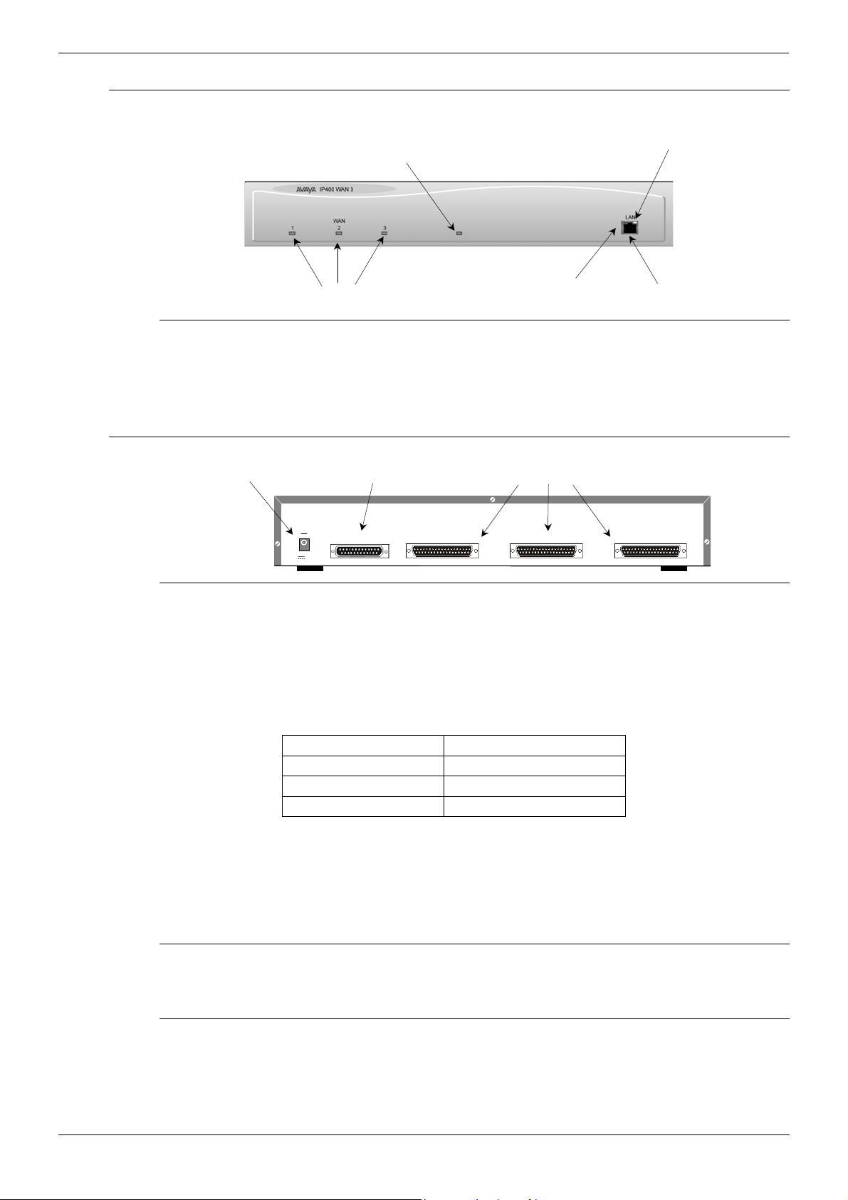
Page 26 — IP400 WAN3 Expansion Modules
IP400 WAN3
Front View
Unit Status LED
Red = Alive but not ini tiated
Green = Running OK
Yellow LE
LAN Activity Indicato
Port connections
• LAN Port: The LAN Port is the expansion port and permits connection to an IP403,
IP406 or IP412 Office platform LAN Port. A LAN Interconnect cable (see page 70) is
required for connection to an IP403 or IP406 and an IP412 requires a Crossover cable
(see page 72).
Rear View
Port connections
• WAN Ports: These ports support a single synchronous data connection, which can be
X.21, V.35 or V.24/V.28. The selection of the required interface is automatically
determined from the pin-out of the cable plugged into the WAN port. This cable must
be connected before power is applied for auto detection to work. Connection to a
Digital Leased Circuit is made by connecting the WAN port on the rear of the unit to the
existing Network Terminating Unit (NTU) via the appropriate X.21, V.35 or V.24 cable.
These cables are detailed in the table below (see pages 74, 75 and 76 for details).
These WAN ports are identical to those on the IP403/406/412 Office platforms (see
pages 12, 16 and 20).
• DC Power I/P Socket: Socket for the external 24V DC unregulated power supply
(supplied with kit).
• DTE Port: A 25-way D-type socket. Used for connection to PC (as a diagnostic aid).
WAN Link Stat us 1 — 3
DC Power I/P Socket
DC I/P
— C +
24V DC
2A
Cable Type SAP Code
V.24/V.28 Cable 700213416
V.35 Cable 700213408
X.21 Cable 700213424
Green LE
LAN Link O
DTE Port
DTE
WAN 1 WAN 1
WAN Ports 1-3
WAN 1
LAN Por
Cables
IP400 WAN3 is supplied with one green LAN Interconnect cable. For Port Pinouts and
Cables, refer to pages 63 and 67 respectively.
Functional Earth
For Functional Earth connections see page 35.
Page 26 — Expansion Modules IP Office Installation Manual
IP400 WAN3 40DHB0002USCL – Issue 9 (28th October 2003)
Loading…
- Инструкции и руководства
- Бренды
- Avaya
- Телефоны
| Продукт | Модель |
|---|---|
| #22426 | |
| Листовка (English) |
| Продукт | Модель |
|---|---|
| 03-300686 | |
| Справочник Пользователя (English) |
| Продукт | Модель |
|---|---|
| 1403 | 700469927 |
| Справочник Пользователя (English) | |
| 1608/1616 | |
| Листовка (English) | |
| 1200 | |
| Справочник Пользователя (English) | |
| 150 MXP | |
| Справочник Пользователя (English) | |
| 1400 Series | |
| Справочник Пользователя (English) | |
| 16CC | |
| Справочник Пользователя (English) | |
| 16-603578 | |
| Справочник Пользователя (English) | |
| 16xx | |
| Справочник Пользователя (English) | |
| 1230 IP | |
| Справочник Пользователя (English) | |
| 10U100 | |
| Справочник Пользователя (English, Français, Español) | |
| 1030 | 3070 |
| Руководство Пользователя (English)Руководство Пользователя (English)Руководство Пользователя (English)Справочник Пользователя (English) | |
| 10bs | 2500 ymgk, 5bs, 7102, bis10, bis22, bis22d, bis34, bis34d, dss, mlx-10Показать ещё
, mlx-10d, mlx-10dp, mlx-16dp, mlx-20l, mlx-28d, mlx-5, mlx-5d, sp34d Скрыть |
| Справочник Пользователя (English)Краткое Руководство По Установке (English)Руководство Пользователя (English)Руководство По Работе (English)Руководство Пользователя (English)Руководство Пользователя (English)Краткое Руководство По Установке (English)Руководство Пользователя (English)Руководство Пользователя (English)Инструкции По Обслуживанию (English)Справочное Руководство (English)Краткий Справочник (English) | |
| 18d | 34d, mlc-5, mlc-6, mls 12, mls 12d, mls 18d, mls 34d, mls 6 |
| Краткий Справочник (English)Справочник Пользователя (English)Руководство По Подключению (English)Дополнительное Руководство (English)Справочник Пользователя (English)Руководство Пользователя (English) | |
| 1224 | 2448, 308, 616 |
| Справочник Пользователя (English)Руководство Пользователя (English)Справочное Руководство (English)Руководство Пользователя (English) | |
| 1010 | |
| Справочник Пользователя (English) |
| Продукт | Модель |
|---|---|
| 2420 | 700381585-IM |
| Справочник Пользователя (English)Листовка (English)Краткий Справочник (English)Справочник Пользователя (English)Справочник Пользователя (English)Справочник Пользователя (English) | |
| 2554 YMGP | |
| Справочник Пользователя | |
| 201-type | |
| Справочник Пользователя (English) | |
| 200-Type Module Analog | |
| Справочник Пользователя (English) | |
| 2060 | |
| Справочник Пользователя (English) | |
| 206 | 410 |
| Дополнительное Руководство (English)Дополнительное Руководство (English)Справочник Пользователя (English) |
| Продукт | Модель |
|---|---|
| 3.1.0 | |
| Справочник Пользователя (English) | |
| 3600 | |
| Справочник Пользователя (English) | |
| 3600 Series | |
| Справочник Пользователя (English) | |
| 3.0.0 | |
| Справочник Пользователя (English) | |
| 3641/3645 | |
| Листовка (English) | |
| 3631 | |
| Справочник Пользователя (English) | |
| 3410 | 3420 |
| Руководство Пользователя (English)Руководство Пользователя (English) | |
| 302a | 302b |
| Краткий Справочник (English)Краткий Справочник (English) | |
| 3749 | |
| Справочное Руководство (English, Deutsch, Español, …)Руководство Пользователя (English) |
| Продукт | Модель |
|---|---|
| 4412D+ | |
| Справочник Пользователя (English) | |
| 4610 | |
| Справочник Пользователя (English)Руководство Пользователя (English)Справочник Пользователя (English) | |
| 4600 Series | |
| Справочник Пользователя (English) | |
| 4424LD+ | |
| Справочник Пользователя (English) | |
| 4424D+ | |
| Справочник Пользователя (English)Руководство Пользователя (English)Руководство Пользователя (English) | |
| 4400d | |
| Руководство Пользователя (English)Release Note (English) | |
| 4624 | |
| Руководство Пользователя (English)Справочник Пользователя (English) | |
| 4690IP | |
|
Инструкция для Avaya 4690IP скоро будет доступна. |
|
| 4406D+, 4412D+, 4424D+, 4424LD+ | |
|
Инструкция для Avaya 4406D+, 4412D+, 4424D+, 4424LD+ скоро будет доступна. |
| Продукт | Модель |
|---|---|
| 5410 | 700345291-IM |
| Справочник Пользователя (English)Листовка (English) | |
| 5602 | |
| Справочник Пользователя (English) | |
| 5420 + EU24 | |
| Справочник Пользователя (English) | |
| 555-233-116 | |
| Справочник Пользователя (English) | |
| 5620 | |
| Справочник Пользователя (English) | |
| 518-456-161 | |
| Справочник Пользователя (English) |
| Продукт | Модель |
|---|---|
| 6408D+ | |
| Справочник Пользователя (English)Справочное Руководство (English) | |
| 6402D | |
| Дополнительное Руководство (English)Руководство Пользователя (English)Руководство Пользователя (English)Справочник Пользователя (English) | |
| 6408+ | |
| Справочник Пользователя (English) | |
| 6416D+ | |
| Справочник Пользователя (English) | |
| 6400 Series | |
| Справочник Пользователя (English) | |
| 6402 | |
| Руководство Пользователя (English)Справочник Пользователя (English)Краткий Справочник (English)Справочник Пользователя (English)Справочник Пользователя (English)Справочник Пользователя (English)Дополнительное Руководство (English) | |
| 6424D+ | |
| Справочник Пользователя (English) | |
| 6201 | 6210, 6220 |
| Справочное Руководство (English)Руководство Пользователя (English) | |
| 6218 | 6220 |
| Справочник Пользователя (English) | |
| 6220 | 6225 |
|
Инструкция для Avaya 6220 скоро будет доступна. |
|
| 6211 | |
| Руководство Пользователя (English)Справочник Пользователя (English)Руководство Пользователя (English)Руководство Пользователя (English)Справочник Пользователя (English)Справочник Пользователя (English)Руководство Пользователя (English)Справочник Пользователя (English)Руководство Пользователя (English)Краткий Справочник (English) | |
| 6219 | 6221 |
| Краткий Справочник (English) |
| Продукт | Модель |
|---|---|
| 700217243 | |
| Справочник Пользователя (English) | |
| 700361330 | |
| Справочник Пользователя (English) | |
| 7313h | 7314h, 7315h, 7316h, 7317h |
| Справочник Пользователя (English)Справочник Пользователя (English) | |
| 7402 plus | |
| Справочник Пользователя (English) | |
| 7406bis | |
| Справочник Пользователя (English) | |
| 7410 plus | |
| Справочник Пользователя (English) | |
| 7444 | |
| Справочник Пользователя (English) | |
| 7505 | 7506, 7507 |
| Справочник Пользователя (English) |
| Продукт | Модель |
|---|---|
| 8101 | 8102, 8110 |
| Справочник Пользователя (English)Справочник Пользователя (English)Справочник Пользователя (English) | |
| 8403 | |
| Справочник Пользователя (English)Справочник Пользователя (English) | |
| 8405 | |
| Краткий Справочник (English)Руководство Пользователя (English) | |
| 8410 | |
| Справочник Пользователя (English)Справочник Пользователя (English)Руководство Пользователя (English) | |
| 8434 | |
| Руководство Пользователя (English)Справочник Пользователя (English) | |
| 8434dx | |
| Справочник Пользователя (English) | |
| 8503t | |
| Справочник Пользователя (English) | |
| 8520t | |
| Справочник Пользователя (English) |
| Продукт | Модель |
|---|---|
| 9103 | |
| Справочник Пользователя (English) | |
| 9600 | |
| Справочник Пользователя (English) | |
| 9600 Series | |
| Справочник Пользователя (English) | |
| 9101 | |
| Справочник Пользователя (English) | |
| 9335-AV | |
| Справочник Пользователя (English) | |
| 9640G | |
| Справочник Пользователя (English)Руководство Пользователя (English) | |
| 96xx | |
| Справочник Пользователя (English) | |
| 9110 | |
| Руководство Пользователя (English) | |
| 9601 | |
| Краткий Справочник (English)Справочник Пользователя (English) |
| Продукт | Модель |
|---|---|
| Audix | |
| Листовка (English) | |
| Aria | |
| Листовка (English) |
| Продукт | Модель |
|---|---|
| BM32 | |
| Справочник Пользователя (English) | |
| bis 10 | bis 22, bis 34, bis22d, bis34d |
| Справочное Руководство (English)Справочное Руководство (English)Инструкции По Обслуживанию (English)Краткое Руководство По Установке (English) |
| Продукт | Модель |
|---|---|
| Communications System | |
| Справочник Пользователя (English) | |
| callmaster ii | callmaster iii |
| Справочное Руководство (English)Руководство Пользователя (English)Справочное Руководство (English)Справочник Пользователя (English)Краткий Справочник (Português, Français, Nederlands, …)Справочник Пользователя (English)Краткий Справочник (Português, Français, Nederlands, …) | |
| callmaster iv | |
| Инструкции По Установке (English) | |
| cm018-kst-2 | |
| Справочник Пользователя (English) |
| Продукт | Модель |
|---|---|
| Desk | |
| Справочник Пользователя (English) | |
| definity callmaster v | |
| Справочник Пользователя (English) | |
| deskphone ntys20dc70e6 | |
| Справочник Пользователя (English) | |
| Definity 6211 | |
|
Инструкция для Avaya Definity 6211 скоро будет доступна. |
|
| Definity 8405 | |
|
Инструкция для Avaya Definity 8405 скоро будет доступна. |
|
| Definity 8434DX | |
|
Инструкция для Avaya Definity 8434DX скоро будет доступна. |
|
| Definity Callmaster IV | |
|
Инструкция для Avaya Definity Callmaster IV скоро будет доступна. |
|
| Definity 8410 | |
|
Инструкция для Avaya Definity 8410 скоро будет доступна. |
|
| Definity Callmaster II | |
|
Инструкция для Avaya Definity Callmaster II скоро будет доступна. |
|
| Definity 6402D | |
|
Инструкция для Avaya Definity 6402D скоро будет доступна. |
|
| Definity 6408 | |
|
Инструкция для Avaya Definity 6408 скоро будет доступна. |
|
| Definity 6402 | |
|
Инструкция для Avaya Definity 6402 скоро будет доступна. |
|
| Definity 8102 | |
|
Инструкция для Avaya Definity 8102 скоро будет доступна. |
|
| Definity 6219 | |
|
Инструкция для Avaya Definity 6219 скоро будет доступна. |
|
| Definity 8101 | |
|
Инструкция для Avaya Definity 8101 скоро будет доступна. |
| Продукт | Модель |
|---|---|
| EU24 | 700381817 |
| Листовка (English)Справочник Пользователя (English)Справочник Пользователя (English) | |
| EC500 | |
| Руководство Пользователя (English)Справочник Пользователя (English) | |
| EA20R | |
| Справочник Пользователя (English) | |
| EA401 | |
| Справочник Пользователя (English) | |
| etr | mls |
| Руководство Пользователя (English) | |
| EHS5 #22426 | |
|
Инструкция для Avaya EHS5 #22426 скоро будет доступна. |
| Продукт | Модель |
|---|---|
| INDeX 11.0 | |
| Справочник Пользователя (English) | |
| integral d3 | |
| Руководство По Подключению (Deutsch, English, Español, …)Руководство Пользователя (English) | |
| ip office 2410 | |
| Справочник Пользователя (English)Справочник Пользователя (English) | |
| ip office 5410 | |
| Справочник Пользователя (English)Справочник Пользователя (English) | |
| ip office 4600 | |
| Справочник Пользователя (English)Справочник Пользователя (English) | |
| index 2050 | |
| Справочник Пользователя (English) | |
| index 2030 | |
| Справочник Пользователя (English) | |
| ip office 5420 | |
| Справочник Пользователя (English) | |
| IP OFFICE 2420 | |
|
Инструкция для Avaya IP OFFICE 2420 скоро будет доступна. |
| Продукт | Модель |
|---|---|
| MDW 9040 | |
| Справочник Пользователя (English)Справочник Пользователя (English)Краткий Справочник (English)Справочник Пользователя (English) | |
| merlin legend end user training | |
| Листовка (English)Справочник Пользователя (English) | |
| M7310 | |
| Справочник Пользователя (English) | |
| mdc 9000 | |
| Справочник Пользователя (English)Справочник Пользователя (English)Справочник Пользователя (English)Справочник Пользователя (English) | |
| mdw 9030p | |
| Краткий Справочник (English) | |
| mdw 9031 | mdw 9031dcp |
| Справочное Руководство (English)Краткий Справочник (English)Справочное Руководство (English)Краткий Справочник (English) | |
| merlin ii | |
| Руководство Пользователя (English) | |
| mlc-6 | |
| Краткое Руководство По Установке (English) | |
| merlin plus | |
| Руководство Пользователя (English)Справочник Пользователя (English) | |
| mlc-5 | |
| Дополнительное Руководство (English) | |
| Merlin BIS 10 | |
|
Инструкция для Avaya Merlin BIS 10 скоро будет доступна. |
| Продукт | Модель |
|---|---|
| null 3711 | |
| Справочник Пользователя (English) |
| Продукт | Модель |
|---|---|
| One-X for RIM Blackberry | |
| Справочник Пользователя (English) | |
| office 5410 | |
| Справочник Пользователя (English) | |
| one-X 9600 Series | |
|
Инструкция для Avaya one-X 9600 Series скоро будет доступна. |
|
| one-X 16-603578 | |
|
Инструкция для Avaya one-X 16-603578 скоро будет доступна. |
|
| ONE-X 3.0.0 | |
|
Инструкция для Avaya ONE-X 3.0.0 скоро будет доступна. |
|
| ONE-X 3.1.0 | |
|
Инструкция для Avaya ONE-X 3.1.0 скоро будет доступна. |
| Продукт | Модель |
|---|---|
| Partner 34D | |
|
Инструкция для Avaya Partner 34D скоро будет доступна. |
|
| Partner 18 | |
|
Инструкция для Avaya Partner 18 скоро будет доступна. |
|
| Partner MLS 12D | |
|
Инструкция для Avaya Partner MLS 12D скоро будет доступна. |
| Продукт | Модель |
|---|---|
| T3 (IP) Comfort | |
| Справочник Пользователя (English)Руководство Пользователя (English) | |
| Trimline | |
| Справочник Пользователя (English) | |
| T3 (IP) Compact | |
| Справочник Пользователя (English) | |
| t3 classic | |
| Руководство Пользователя (English) | |
| t3 compact | |
| Справочник Пользователя (English) | |
| t3 comfort | |
|
Инструкция для Avaya t3 comfort скоро будет доступна. |
|
| TransTalk MDW 9040 | |
|
Инструкция для Avaya TransTalk MDW 9040 скоро будет доступна. |
| Продукт | Модель |
|---|---|
| Wall | |
| Справочник Пользователя (English) |
Most Searched Power Supply User Instructions:
G-02X, PDW-F800, AP 100, AE5723, MASS-VIEW series, SMART750SLT
FAQ
What are the key features of Avaya’s power supply products?
Avaya’s power supply products are known for their high efficiency, reliability, and advanced power management capabilities, ensuring uninterrupted power supply to critical communication systems.
How does Avaya ensure the quality and reliability of its power supply products?
Avaya puts its power supply products through rigorous testing and quality control processes to meet industry standards and customer expectations, ensuring they perform optimally in all conditions.
Are Avaya’s power supply products energy-efficient?
Yes, Avaya’s power supply products are designed with energy efficiency in mind, helping businesses save on energy costs while minimizing their environmental impact.
Does Avaya offer a wide range of power supply solutions for different business needs?
Yes, Avaya offers a diverse range of power supply solutions to cater to various business needs, from small businesses to large enterprises, ensuring reliable power for communication systems.
How does Avaya support its customers in choosing the right power supply product?
Avaya provides comprehensive support to its customers, offering consultation services and guidance to help them select the most suitable power supply product for their specific requirements.
Are Avaya’s power supply products customizable for specific use cases?
Yes, Avaya’s power supply products can be customized to meet specific use cases, allowing businesses to tailor the power supply solution to their unique needs and infrastructure.
Does Avaya provide maintenance and servicing for its power supply products?
Yes, Avaya offers maintenance and servicing support for its power supply products to ensure optimal performance and longevity, helping customers protect their investment in critical communication systems.