
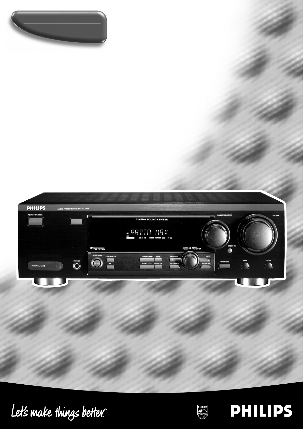
Surround sound receiver
FR740
FR760
MX740

Important notes for users in the U.K.
Mains plug
This apparatus is fitted with an approved 13 Amp plug.
To change a fuse in this type of plug proceed as follows:
1 Remove fuse cover and fuse.
2
Fix new fuse which should be a
BS1362
5 Amp, A.S.T.A. or BSI approved type.
3 Refit the fuse cover.
If the fitted plug is not suitable for your socket outlets, it
should be cut off and an appropriate plug fitted in its place.
If the mains plug contains a fuse, this should have a value
of 5 Amp. If a plug without a fuse is used, the fuse at the
distribution board should not be greater than 5 Amp.
Note: The severed plug must be disposed of to avoid a
possible shock hazard should it be inserted into a 13 Amp
socket elsewhere.
How to connect a plug
The wires in the mains lead are coloured with the following
code: blue = neutral (N), brown = live (L).
As these colours may not correspond with the colour
mark
ings identifying the terminals in your plug, proceed as
follows:
• Connect the blue wire to the terminal marked N or
coloured black.
• Connect the brown wire to the terminal marked L or
coloured red.
•
Do not connect either wire to the earth terminal in the
plug,
marked E (or e) or coloured green (or green and
yellow).
Before replacing the plug cover, make certain that the cord
grip is clamped over the sheath of the lead — not simply over
the two wires.
Copyright in the U.K.
Recording and playback of material may require consent.
See
Copyright Act 1956 and The Performer’s Protection Acts
1958 to 1972.
Typeskilt finnes på apparatens bakside.
Observer: Nettbryteren er sekundert innkoplet. Den
innebygde netdelen er derfor ikke frakoplet nettet så lenge
apparatet er tilsluttet nettkontakten.
For å redusere faren for brann eller elektrisk støt, skal
apparatet ikke utsettes for regn eller fuktighet.
Norge
DICHIARAZIONE DI CONFORMITA’
Si dichiara che gli apparecchi FR 740, FR 760 e MX 740
Philips rispondono alle prescrizioni dell’art. 2 comma 1 del
D. M. 28 Agosto 1995 n. 548.
Fatto a Eindhoven, il 01/02/2000 (FR 740, MX 740)
Fatto a Eindhoven, il 01/03/2000 (FR 760)
Philips Consumer Electronics
Philips, Glaslaan 2
5616 JB Eindhoven, The Netherlands
Italia
2

3
English …………………………………………….4
Français………………………………………….24
Español ………………………………………….44
Deutsch………………………………………….64
Nederlands …………………………………….84
EnglishFrançaisEspañolDeutschNederlands
Italiano
Italiano…………………………………………104
GENERAL INFORMATION
4
This receiver is supplied including:
– a remote control
– 2 batteries for the remote control, size AA
– a system bus cable for the CINEMA LINK connection
– a loop antenna
– a wire antenna
– 5 loudspeakers including 5 speaker cables (MX 740 only)
– a quick installation card (MX 740 only)
– this instruction booklet
Clean the receiver with a soft,
slightly dampened, lint-free cloth.
Do not use any cleaning agents as
they may have a corrosive effect.
Do not expose the receiver to
humidity, rain, sand or excessive heat
(caused by heating equipment or
direct sunlight).
If you have stacked the components of your system, the
receiver must be on top. Place the receiver on a flat,
hard, stabile surface. Do not cover any vents and leave
50 cm above and 10 cm left and right of the receiver
free for ventilation.
For good reception the loop antenna should not be placed on
top of, or beneath VCRs, CD recorders, DVD players, TVs and
other radiation sources.
All redundant packing material has been omitted. We have
done our utmost to make the packaging easily separable into
three mono materials: cardboard (box), polystyrene foam
(buffer) and polyethylene (bags, protective foam sheet).
Your set consists of materials which can be recycled if
disassembled by a specialized company. Please observe the
local regulations regarding the disposal of packing materials,
exhausted batteries and old equipment.
“DOLBY”, “DOLBY DIGITAL”, “PRO LOGIC” and the
double-D symbol 2 are trademarks of Dolby Laboratories.
Trademark acknowledgment
Environmental information
Setup
Maintenance
Scope of supply
English
General information
Scope of supply……………………………………………………………………….4
Maintenance …………………………………………………………………………..4
Setup ……………………………………………………………………………………..4
Environmental information………………………………………………………..4
Trademark acknowledgment……………………………………………………..4
Controls …………………………………………………………………………………….5
Remote control
Remote control usage………………………………………………………………6
Remote control buttons ……………………………………………………………7
Connectors………………………………………………………………………………..8
Connections
Audio connections……………………………………………………………………9
System control bus, CINEMA LINK ………………………………………….10
Video connections (FR 760 only)………………………………………………10
Mains …………………………………………………………………………………..11
Speaker connections………………………………………………………………11
TV as the center speaker………………………………………………………..11
Antenna connections ……………………………………………………………..11
FRONT AV /GAME cap (FR 760 only)……………………………………….11
System setup
Positioning of the speakers …………………………………………………….12
Speaker setup and testing………………………………………………………12
Power handling ……………………………………………………………………..12
Headphones ………………………………………………………………………….12
Display…………………………………………………………………………………….13
Menus
Receiver menu……………………………………………………………………….14
TV menu ……………………………………………………………………………….15
Source selection
SOURCE SELECTOR………………………………………………………………..16
About 6 CHANNEL / DVD INPUT……………………………………………..16
Playback, recording
Playing a source…………………………………………………………………….17
Adjusting the sound……………………………………………………………….17
Recording from a source…………………………………………………………17
Surround sound
About surround sound…………………………………………………………….18
Switching surround sound ………………………………………………………18
Surround sound settings…………………………………………………………18
Tuner
Tuning to radio stations………………………………………………………….19
Switching FM sensitivity ………………………………………………………..19
Storing radio stations …………………………………………………………….19
Tuning to stored radio stations………………………………………………..20
Resorting stored radio station…………………………………………………20
Naming radio stations ……………………………………………………………20
Clearing station names…………………………………………………………..20
RDS R………………………………………………………………………………….21
RDS News and Traffic Announcement……………………………………..21
Technical data
Receiver………………………………………………………………………………..22
Speakers (supplied with MX 740 only)……………………………………..22
Troubleshooting
Warning………………………………………………………………………………..23
Troubleshooting……………………………………………………………………..23
This product complies with the radio interference
requirements of the European Community.
As an ENERGY STAR®partner, Philips has determined that
this product meets the ENERGY STAR
®
guidelines for energy efficiency.

CONTROLS
5
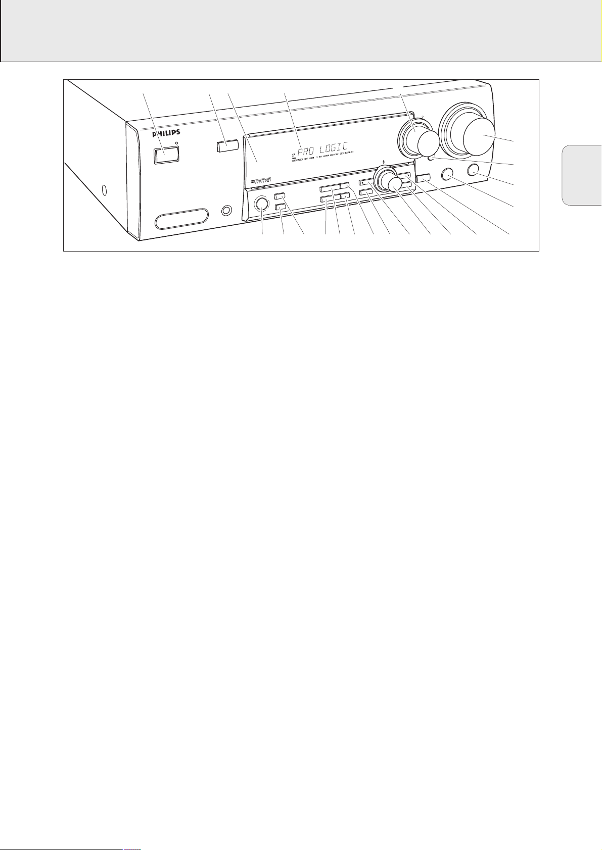
1 POWER / STANDBY…….Switches the receiver on and off.
2 CINEMA LINK …………….Switches the system control bus
between the receiver and the TV
on and off.
3 ……………………………………Sensor for the infrared remote
control.
4 ……………………………………Display
5 SOURCE SELECTOR ……Selects the different audio and
video connectors.
6 VOLUME……………………..Increases and decreases the
volume level.
7 FRONT AV…………………..Selects the FRONT AV / GAME
input (FR 760 only).
8 TREBLE……………………….Adjusts the treble when used in
combination with VOLUME.
9 BASS ………………………….Adjusts the bass when used in
combination with VOLUME.
0 LOUDNESS …………………Switches LOUDNESS on and off.
! NEXT 2 ………………………TUNER: searches radio stations.
MENU: switches to the next
menu level.
@ ENTER / OK…………………Confirms selected menu values.
# TUNER PRESET X MENU NAVIGATOR
TUNER: switches to the next and
previous stored radio station.
MENU: moves upwards and
downwards.
$ 1 PREV. / EXIT ……………TUNER: searches radio stations.
MENU: switches to the previous
menu level.
% SETUP MENU …………….Switches the menu on and off.
^ SENS. …………………………Switches between low and high
tuner sensitivity.
& NEWS/TA……………………Switches the RDS news and
RDS traffic announcement on
and off.
* TUNER AM/FM …………..Switches the wavebands of the
tuner.
( RADIO TEXT ……………….Scrolls through the different RDS
information.
) SURR. MODE………………Switches through the different
speaker configurations.
¡ HALL …………………………..Switches HALL on and off.
™ SURROUND ON/OFF …..Switches between the last
selected surround mode and
stereo.
English
1 23 4 5
CINEMA SOUND CENTER
SENS.
TUNER AM/FM
NEWS/TA
RADIO TEXT
PREV. / EXIT
SETUP MENU
MENU
TUNER
NAVIGATOR
PRESET
TER / OK
POWER / STANDBY
FRONT AV / GAME
CINEMA LINK
PHONES
SURROUND
SURR. MODE
HALL
ON/OFF
SOURCE SELECTOR
6CH/DVD
AV
LOUDNESS
BASS
NEXT
VOLUME
6
TREBLE
7
8
9
0!@#$%^&*()¡™

REMOTE CONTROL
6
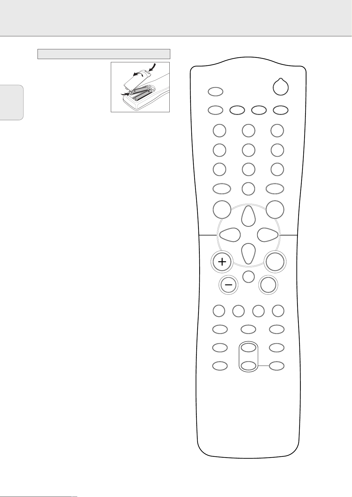
Open the battery compartment
of the remote control and insert
2 alkaline batteries, type AA
(R06, UM-3).
Remove batteries if they are flat
or if the remote control is not
going to be used for a long time.
Batteries contain chemical substances, so they should
be disposed of properly.
The buttons on the remote control work the same way as the
corresponding ones on the receiver.
Additional appliances can only be controlled if they are
working with the RC-5 and the RC-6 code system.
Important!
You have to press a source button for longer than 1 second to
switch the sound source on the receiver. Pressing a source
button for less than 1 second will only switch the remote
control to use the commands for the selected product.
The remote control remains tuned to the selected source until
another source button on the remote control is pressed.
This enables you to operate additional sources (i. e. winding
a tape) without changing the source on the receiver.
Remote control usage
English
TUNER
CD CDR/TAPE VCR TV
1
4
7
CINEMA LINK
2
5
8
0
GUIDE
MENU
2
3
6
9
DVD/6CH
OK
É
AA
H
Ç
CHANNEL/TRACK
íëÅ
b
REAR
±
+
—
CHANNEL
FR.D/INDEXPAUSE
SURR. ON/OFFDISPLAY/T-C NEWS/TA
SURR. MODESMART SOUND
TEST TONELOUDNESS
TV
DISC

REMOTE CONTROL
7
English
2 …………………………..Switches the receiver to standby.
TUNER, CD, CDR/TAPE,
TV, VCR, DVD/6CH……..Switches the remote control to the
commands of the different products.
Selects the sources if pressed longer
than 1 second.
1–0…………………………..Keys in numbers for tracks, stations or
frequencies. Numbers consisting of
two figures must be keyed in within
2 seconds.
CINEMA LINK……………Switches the connection between the
receiver and the TV on and off.
MENU GUIDE …………..TUNER: Switches the receiver menu
on and off.
DVD, TV: Switches the DVD/TV menu
on and off.
OK……………………………Confirms menu options.
Arrow buttons …………..TUNER: Moves in the menus.
Right/left arrows are tuning up/down.
CD, CDR: Left/right arrows are
searching backwards/forwards,
up/down arrows are selecting the
next/previous track.
+A………………………Increases the receiver volume.
-A………………………Decreases the receiver volume.
H …………………………..Mutes the sound of the receiver.
ÉATV ………………….Increases the TV volume.
CD, CDR, VCR, DVD: Starts playback.
ÇATV ………………….Decreases the TV volume.
CD, CDR, VCR, DVD: Stops playback.
í
CHANNEL/TRACK
…Selects the previous preset tuner
station.
VCR: Rewinds the tape.
CD, CDR, DVD: Selects the previous
track.
TV: Selects the previous channel.
ë
CHANNEL/TRACK
…Selects the next preset tuner station.
VCR: Fast forwards the tape.
CD, CDR, DVD: Selects the next
track.
TV: Selects the next channel.
Å PAUSE……………….CD, CDR, VCR, DVD: Pauses
playback.
DISC FR.D./INDEX ……..CD-, CDR-, DVD-Changers:
Switches to the next disc.
TUNER: Switches to FREQUENCY
DIRECT.
VCR: Switches the index search on
and off.
b DISPLAY/T-C………..TUNER: Switches between station
name, frequency and radio text.
CD, CDR: Switches between the
different time displays.
TV: Switches teletext on and off.
DVD: Switches between title and
chapter.
NEWS/TA…………………Switches the functions NEWS and
TRAFFIC ANNOUNCEMENT on and off.
SURR. ON/OFF…………..Switches SURROUND SOUND on and
off.
±SMART SOUND ……Scrolls through the different smart
sounds.
+/- REAR ……………Increases/decreases the volume of the
rear speakers. While test tone is on,
the volume of the speakers you are
hearing can be increased/decreased
with these buttons.
SURR. MODE…………….Scrolls through the different surround
modes.
LOUDNESS ……………….Switches LOUDNESS on and off.
TEST TONE ……………….Switches the test tone on and off.
While test tone is on, the volume of
the speakers you are hearing can be
increased/decreased with
+/- REAR.
Remote control buttons
8
English
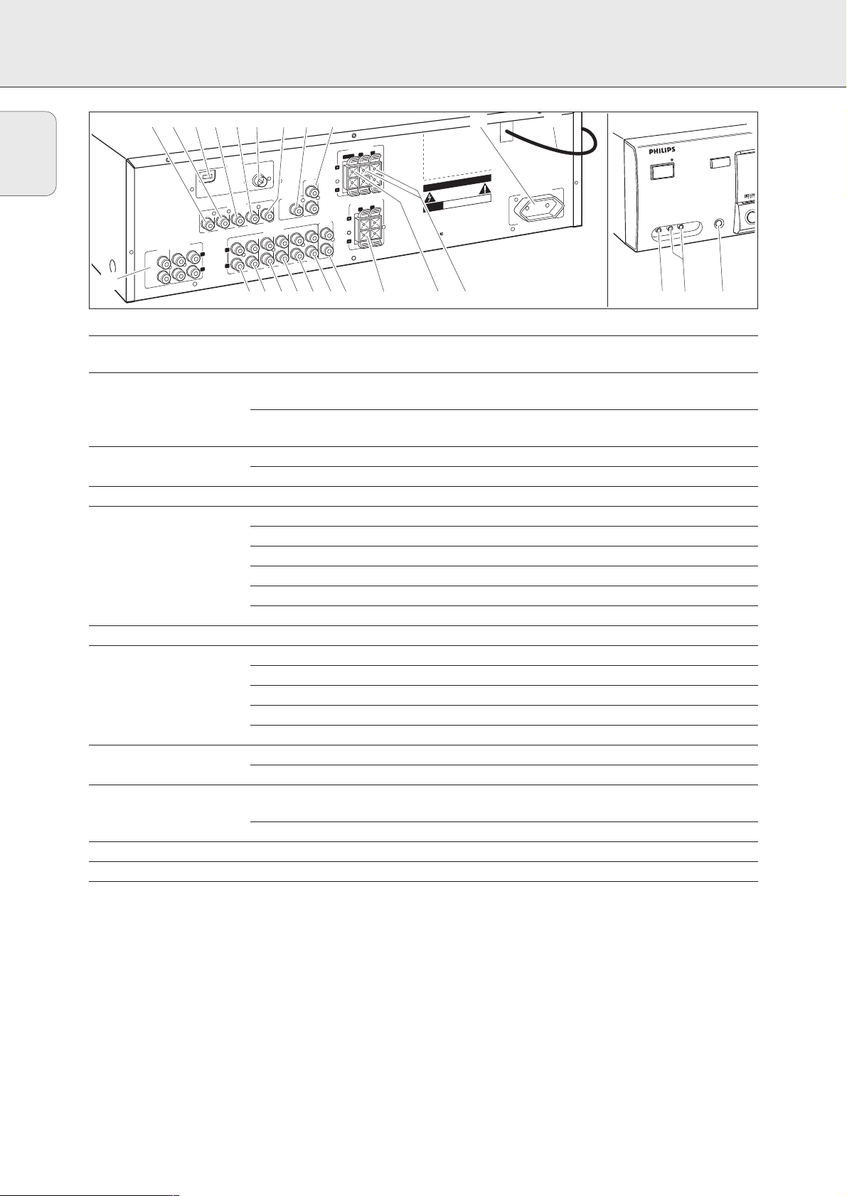
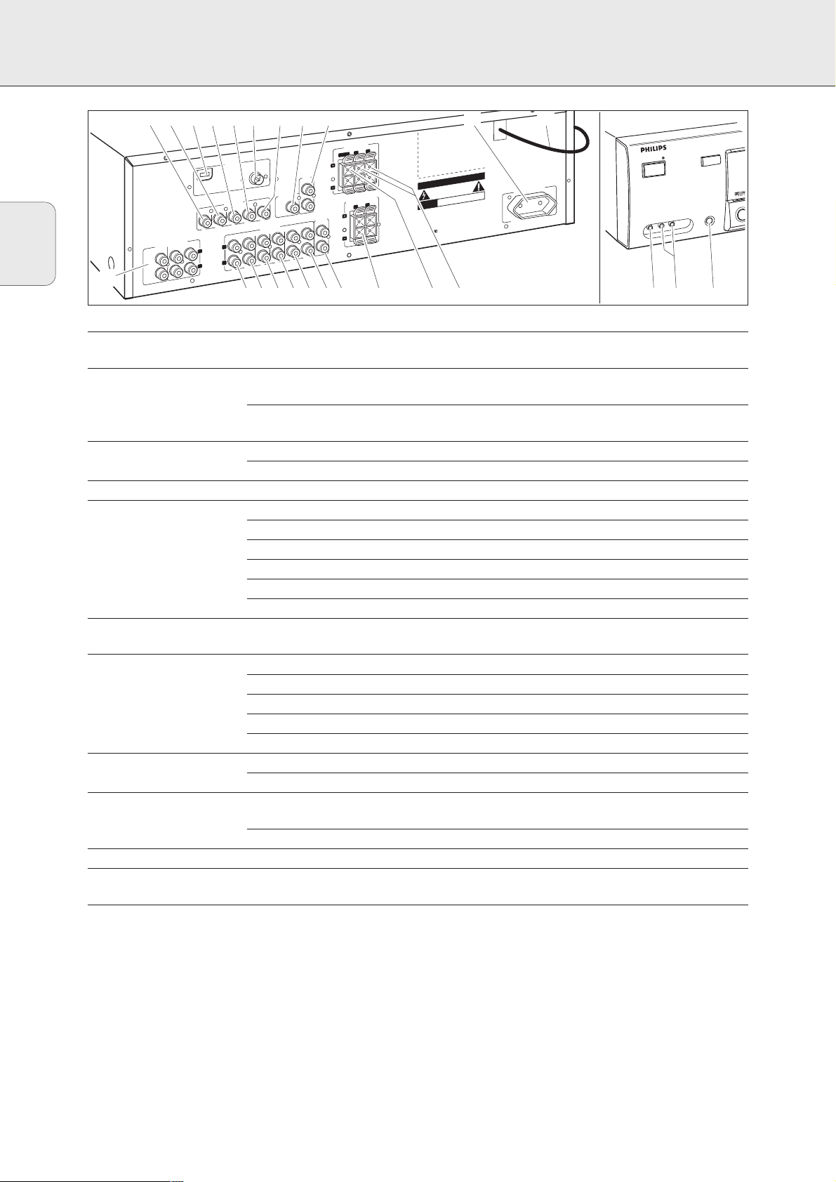
CONNECTORS
Connectors Connectors name Connect to:
6.3 mm headphone socket 1 PHONES A headphone with a 6.3 mm plug.
at the front
Audio and video inputs 2 FRONT AV / GAME Left and right audio out sockets of appliances such as video cameras
at the front (FR 760 only) and game consoles.
3 FRONT AV / GAME Video out sockets of appliances such as video cameras and game
consoles.
FRONT SPEAKERS 4 R, L Right and left front speaker.
5 CENTER Center speaker.
SURROUND SPEAKERS 6 R, L Right and left surround speaker.
AUDIO IN/OUT 8 CDR/TAPE OUT Input of a CD recorder or a tape deck.
9 CDR/TAPE IN Output of a CD recorder or a tape deck.
0 CD IN Output of a CD player.
! TV IN Output of a TV.
@ VCR OUT Input of a video recorder.
# VCR IN Output of a video recorder.
6-channel input $
6 CHANNEL /DVD INPUT
6-channel output of appliances such as DVD or Laserdisc players.
VIDEO IN/OUT (FR 760 only) % DVD IN Output of a DVD player.
^ MON OUT Input of a monitor (e. g. the TV).
* VCR IN Output of a video recorder.
( VCR OUT Input of a video recorder (for recording).
¡ TV IN Output of a TV.
Antenna connectors &
AM LOOP
Frame antenna supplied.
) FM 75 Ω Wire antenna supplied or exterior antenna.
Preamplified outputs 7 CENTER PRE-OUT Input of a TV when it is used as the center speaker (only possible
when the CINEMA LINK system bus is connected).
™
SUBWOOFER PRE-OUT
Input of a powered subwoofer.
System control bus £ CINEMA LINK System control bus sockets of a Philips TV with CINEMA LINK.
Mains outlet ≤ AC OUTLET Supplies same voltage as mains. Up to 100 W total permitted load.
Mains lead ∞ After all other connections have been made, connect the
mains lead to the wall socket.
$
%^&*() ¡™ ≤ ∞
ANTENNA
Ω
75
FM
SUBWOOFER
PRE-OUT
TV
VIDEO IN/OUT
VCR
MON
OUT
IN
OUT
IN
REC
PLAY
AUDIO IN/OUT
CD
TV
VCR
L
R
IN
PLAY
IN
IN
OUT
REC
CENTER
SUBWOOFER
6 CHANNEL / DVD INPUT
SURR.
AM LOOP
DVD
IN
FRONT
L
R
£
FRONT SPEAKERS
≥ 6 Ω
EACH SPEAKER
L
R
CENTER
CINEMA
LINK
SURROUND SPEAKERS
EACH SPEAKER ≥ 3 Ω
L
R
CENTER
PRE-OUT
APE
CDR/T
OUT
IN
REC
PLAY
CAUTION
RISK OF ELECTRIC SHOCK
DO NOT OPEN
RISQUE DE CHOC ELECTRIQUE
AVIS
developed
and
Designed
European Community
Manufactured
Laboratories
«PRO-LOGIC»
are Trademarks
«DOLBY«,
Symbol
Laboratories
under
Licencing
Licencing
NE PAS OUVRIR
by Philips
licence
and the Double-D
from
Corporation.
of Dolby
Corporation.
~50 Hz
230V
AC OUTLET
in the
Dolby
TOTAL 100W MAX. SWITCHED
POWER / STANDBY
3
CINEMA LINK
PHONES
124567890!@#
SURROU
ON/O
9
English
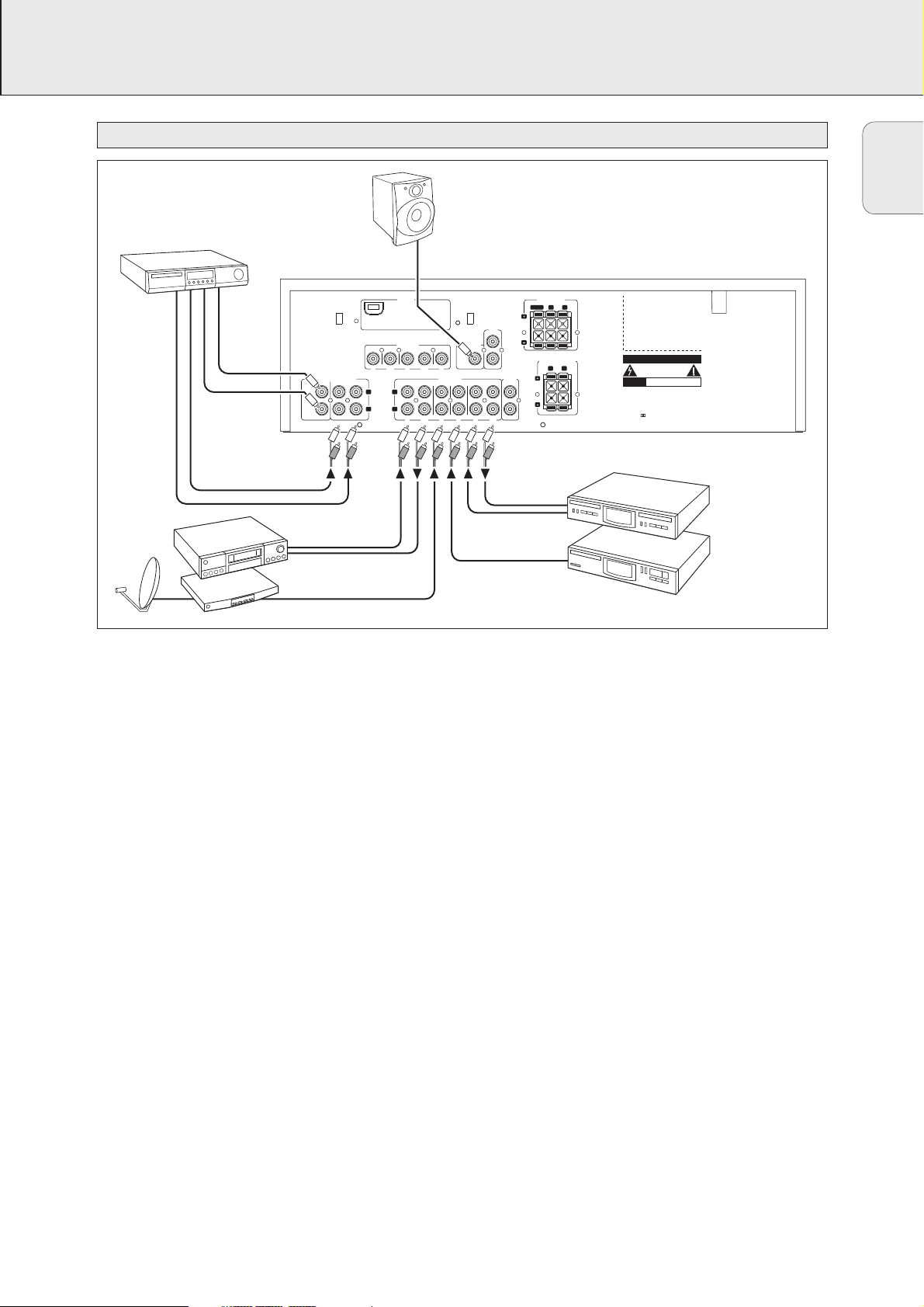
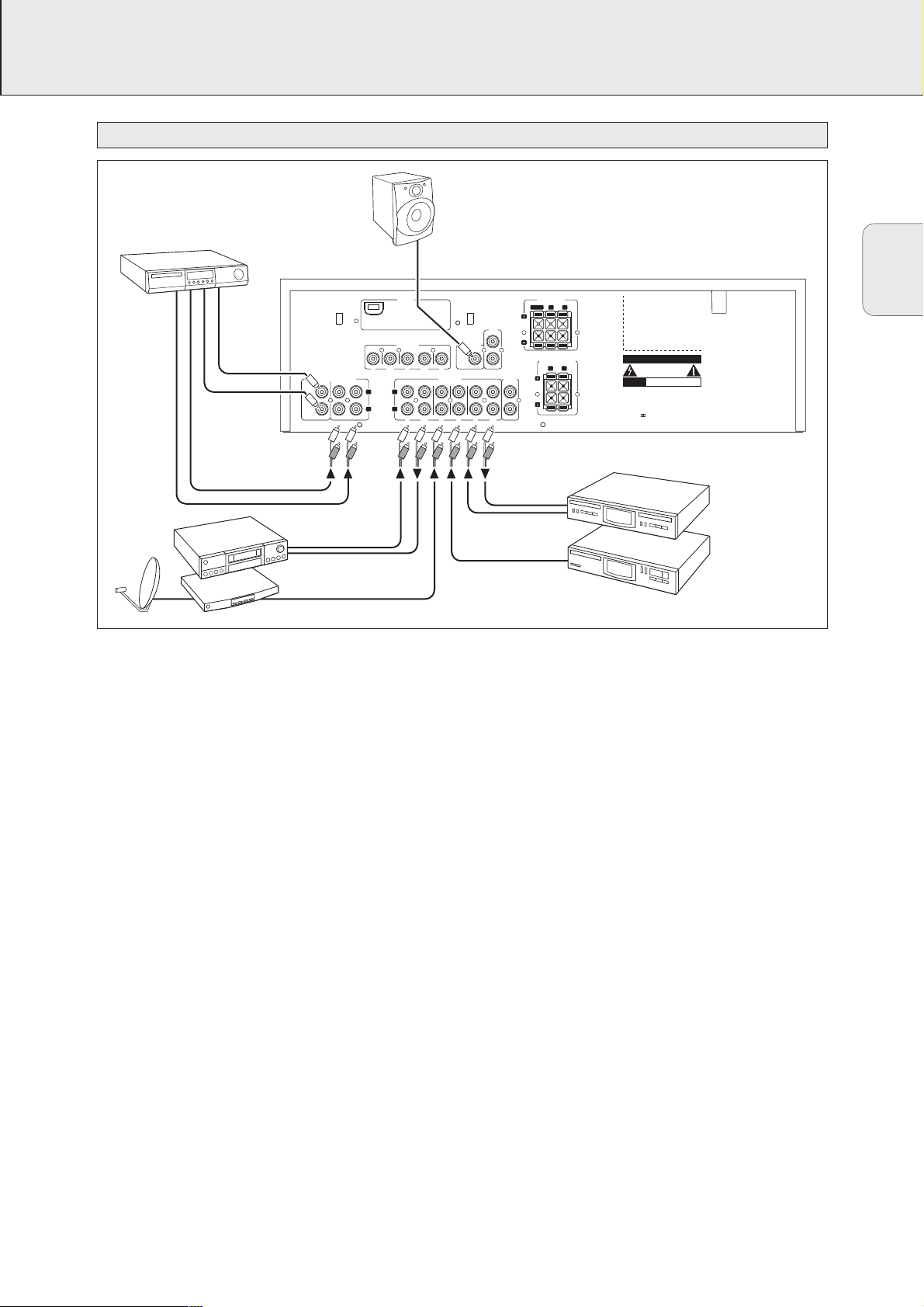
CONNECTIONS
Audio connections
DVD PLAYER
(6 Channel Output)
SUBWOOFER
6 CHANNEL / DVD INPUT
CENTER
SUBWOOFER
VCR
AUDIO OUT
AUDIO IN
SAT RECEIVER
POWERED
FRONTSURR.
ANTENNA
AM LOOP
VIDEO IN/OUT
DVD MON TV/SAT
VCR
IN OUT
L
R
OUT
IN
REC
PLAY
VCR
L
R
IN
OUT
PLAY
REC
SUBWOOFER
PRE-OUT
IN
IN
AUDIO IN/OUT
TV CD CDR/TAPE
IN
IN IN
PLAY
CINEMA
LINK
OUT
REC
FRONT SPEAKERS
EACH SPEAKER ≥ 6 Ω
CENTER
CENTER
PRE-OUT
CD RECORDER
CD PLAYER
R
SURROUND SPEAKERS
EACH SPEAKER ≥ 6 Ω
R
IN
OUT
L
CAUTION
L
RISK OF ELECTRIC SHOCK
DO NOT OPEN
RISQUE DE CHOC
AVIS
ELECTRIQUE
Designed and developed by Philips in the
European Community
Manufactured under licence from Dolby
Laboratories Licencing Corporation.
«DOLBY», «PRO-LOGIC» and the Double-D
Symbol are Trademarks of Dolby
Laboratories Licencing Corporation.
10
English
CONNECTIONS
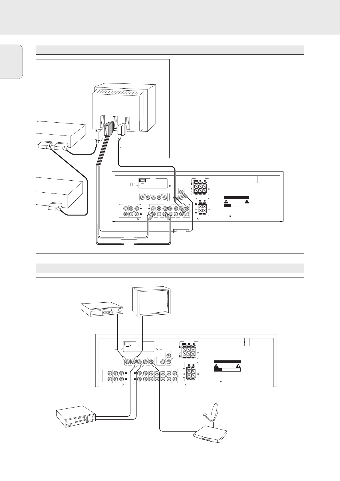
System control bus, CINEMA LINK
Video connections (FR 760 only)
VIDEO IN/OUT
DVD MON TV/SAT
IN OUT
OUT
REC
IN
IN
PLAY
TV CD CDR/TAPE
AUDIO IN/OUT
L
R
IN
PLAY
OUT
REC
IN IN
IN
PLAY
OUT
REC
PRE-OUT
CENTER
6 CHANNEL / DVD INPUT
FRONTSURR.
CENTER
SUBWOOFER
VCR
L
R
VCR
IN
CINEMA
LINK
SUBWOOFER
PRE-OUT
ANTENNA
AM LOOP
FRONT SPEAKERS
L
R
EACH SPEAKER ≥ 6 Ω
CENTER
Designed and developed by Philips in the
European Community
CAUTION
RISK OF ELECTRIC SHOCK
DO NOT OPEN
AVIS
RISQUE DE CHOC
ELECTRIQUE
Manufactured under licence from Dolby
Laboratories Licencing Corporation.
«DOLBY», «PRO-LOGIC» and the Double-D
Symbol are Trademarks of Dolby
Laboratories Licencing Corporation.
R
L
EACH SPEAKER ≥ 6 Ω
SURROUND SPEAKERS
TV to AMP
AUX to AMP
TV
AUX
EXT 1 EXT 2 EXT 3
DVD PLAYER
VCR
TV
optional
(TV = CENTER)
CINEMA LINK
A
If the receiver and your Philips TV (or even better in
addition a Philips VCR or DVD player) with Cinemalink are
connected with the CINEMA LINK system bus control, some
extra system benefits are offered:
– Upon starting a source, the system will automatically
switch to that input.
– You may control the system via the TV screen. Depending
on the language of the TV, this can be done in your
preferred language.
– The TV can function as the center speaker of your system,
making a separate center speaker unnecessary. (The cable
A has to be purchased separately.)
– By pressing the standby button on the remote control you
can switch the complete system to standby.
DVD PLAYER
6 CHANNEL / DVD INPUT
FRONTSURR.
CENTER
SUBWOOFER
VCR
VIDEO OUT
VIDEO IN
ANTENNA
AM LOOP
VIDEO IN/OUT
DVD MON TV/SAT
IN OUT
IN
PLAY
L
L
R
R
IN
PLAY
MONITOR / TV
VCR
IN
OUT
IN
REC
AUDIO IN/OUT
VCR
TV CD CDR/TAPE
IN IN
OUT
REC
SUBWOOFER
PRE-OUT
CINEMA
IN
PLAY
LINK
OUT
REC
CENTER
PRE-OUT
FRONT SPEAKERS
EACH SPEAKER ≥ 6 Ω
R
CENTER
SURROUND SPEAKERS
EACH SPEAKER ≥ 6 Ω
R
L
SAT RECEIVER
L
CAUTION
RISK OF ELECTRIC SHOCK
DO NOT OPEN
RISQUE DE CHOC
AVIS
ELECTRIQUE
Designed and developed by Philips in the
European Community
Manufactured under licence from Dolby
Laboratories Licencing Corporation.
«DOLBY», «PRO-LOGIC» and the Double-D
Symbol are Trademarks of Dolby
Laboratories Licencing Corporation.
11
English
CONNECTIONS
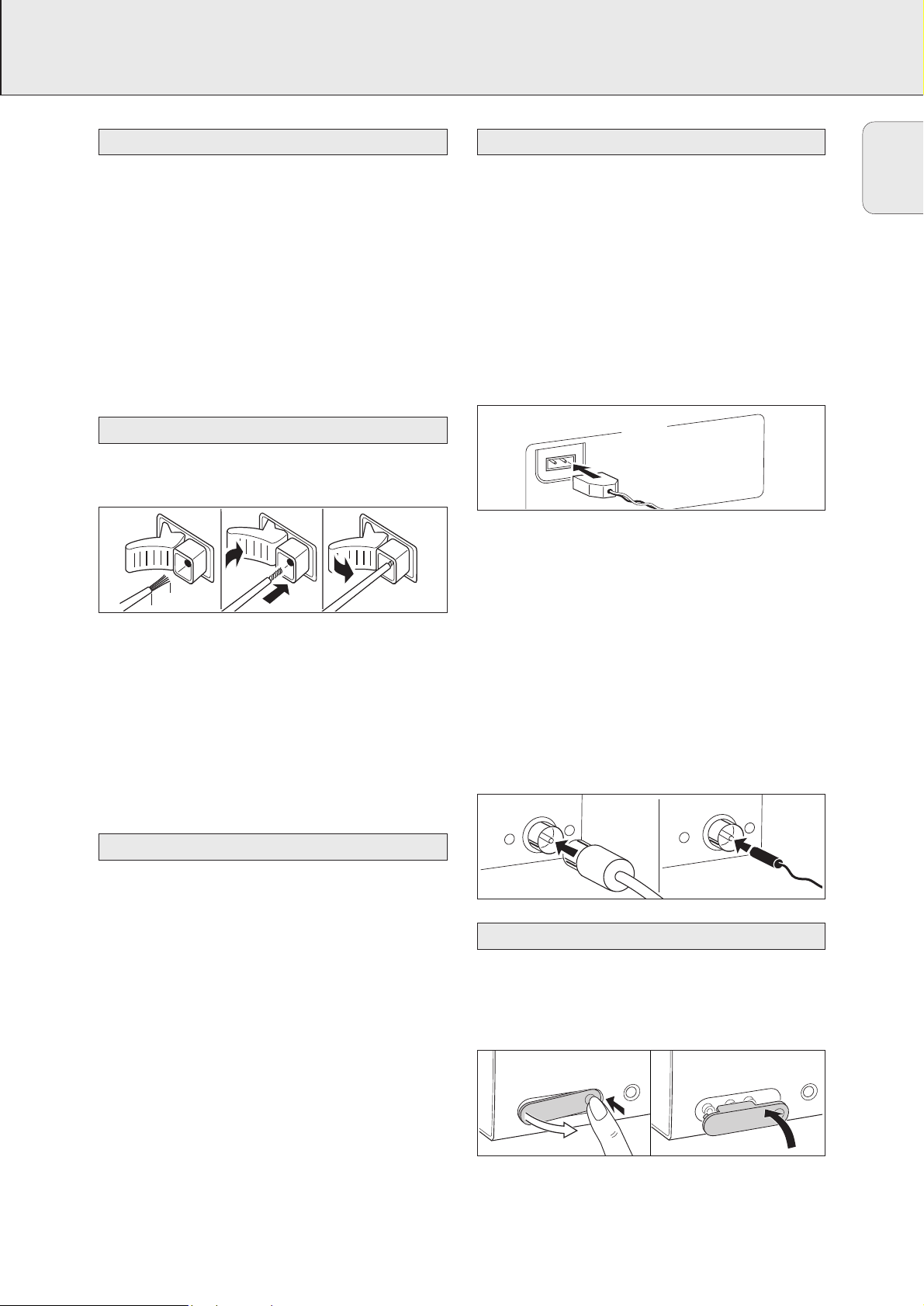
The type plate is located on the rear of the receiver.
1 Check whether the mains voltage as shown on the type
plate corresponds to your local mains voltage. If it does not,
consult your dealer or service organization.
2 Connect the mains cable to the wall socket.
To disconnect the set from the mains completely, remove the
mains plug from the wall socket.
For users in the U. K.: please follow the instructions on
page 2.
The speaker connections on the receiver are click-fit
connectors. Use them as shown below.
1 Always connect the coloured (or marked) wire to the
coloured terminal and the black (or unmarked) wire to the
black terminal.
2 Connect:
– Left front speaker to L (red and black)
– Right front speaker to R (red and black)
– Center speaker to CENTER (blue and black)
– Left surround speaker to SURROUND L (grey and black)
– Right surround speaker to SURROUND R (grey and black)
You may use your Philips TV with CINEMA LINK as the center
speaker. For TVs with a scart connector an additional audio
cinch-to-scart cable is needed. For TV’s with cinch connectors
additional cinch cables are needed. Look into the instruction
manual of your TV on how to use it as the center speaker.
AM (MW) antenna
The loop antenna supplied is for indoor use only. Position the
antenna as far away as possible from the receiver, the TV, the
cables, a DVD player, a VCR and other radiation sources.
1 Fit the plug of the frame antenna to AM LOOP as shown
below.
2 Position the antenna as far away as possible from radiation
sources.
3 Turn the antenna for optimum reception.
FM antenna
The wire antenna supplied can only be used to receive nearby
stations. For better reception we recommend using a cable
antenna system or an outdoor antenna.
1 Fit the supplied wire antenna to FM 75 Ω as shown below.
2 Move the antenna in different positions for optimum
reception.
• If you are using a cable antenna system or an outdoor
antenna, fit the antenna plug to FM 75 Ω instead of the
wire antenna.
• To remove the FRONT AV / GAME cap, press on the right
side of the cap.
• Insert the cap from below to close the compartment.
FRONT AV / GAME cap (FR 760 only)
Antenna connections
TV as the center speaker
Speaker connections
Mains
8 mm
1
2
3
ANTENNA
AM LOOP
FM 75 Ω
FM 75 Ω
PHONES
FRONT AV / GAME
FRONT A
V / GAME
PHONES

SYSTEM SETUP
12
General hints for positioning
Avoid positioning the speakers in a corner or on the floor as
this will boost the bass tones too much. Placing the speakers
behind curtains, furniture, etc. will reduce the treble response.
The listener should always be able to ”see” the speakers.
Each room has different acoustic characteristics and the
positioning possibilities are often limited. You can find the
best position for your speakers by referring to the picture
above.
As a minimum we recommend 5 speakers (2 front, a center,
2 surround) for good surround sound. It is possible to
reproduce some kind of surround sound with fewer speakers.
This is done by redirecting the signals which are foreseen for
the missing speakers to the existing ones. See “Menus” on
how to set up the receiver correctly for the number and size
of the speakers used.
Positioning the front speakers
The front speakers should be placed right and left in front of
the listening position like usual stereo speakers.
Positioning the center speaker
The center speaker should be placed in the center between
the two front speakers, e. g. underneath or on top of the TV.
The best height for the center speaker is the height of the
listener’s ears (while seated).
Positioning the surround speakers
The surround speakers should face each other and be in line
with, or slightly behind the listener.
Positioning the subwoofer
A subwoofer can be used to enhance the bass performance of
your system dramatically. The subwoofer can be positioned
anywhere in the room, because it is not possible to locate the
source of deep tones. Nevertheless, you should not place the
subwoofer in the middle of a room, since the bass could be
severely weakened. Do not place any object on the subwoofer.
The relative volume of the speakers must be adjusted for
optimal surround sound. You should be at your usual listening
position when adjusting the speaker volume. See “Receiver
menus” on how to set up the receiver for the used speakers.
Ideally, the volume in the listening position should be the
same from all speakers.
1 Press POWER / STANDBY to switch on the receiver.
2 Press TEST TONE on the remote control.
y A test tone coming from the different speakers is
heard.
3 Press +/- REAR on the remote control to
increase/decrease the volume of the actual speaker.
4 Press TEST TONE on the remote control.
y The test tone stops.
Note: If you are not completely satisfied with the volume
settings, we recommend making minor adjustments to
them during surround sound playback.
If the receiver is used at very high power, it can produce
distortions which may seriously damage your speakers.
If distortions occur, reduce the volume and the tone controls
to a level where the sound is acceptable again.
To avoid overheating of the set a safety circuit has
been built in. Therefore your set may disconnect under
extreme conditions. If this happens, switch the set off
and let it cool down before reusing it.
Connecting headphones to PHONES will switch off the
speakers. The receiver switches to STEREO and surround
sound will be reduced to a stereo signal which is reproducible
by standard headphones.
Disconnecting the headphones switches on the speakers
again. If you wish to enjoy surround sound again, switch the
receiver back to surround sound.
Headphones
Power handling
Speaker setup and testing
Positioning of the speakers
English
FRONT
RIGHT
RIGHT
SURROUND
(REAR)
SUBWOOFER
SURROUND
(REAR)
CENTER
FRONT
LEFT
LEFT

13
English
DISPLAY
The display of the receiver is divided into 3 sections, which
are to be used for the following:
Menu indication
These signs show you if the menu is on or off and indicate in
which direction you may move.
MMEENNUU …………………..Menu is on.
1…………………………You may move backwards to the previous
menu topic using 1 PREV. / EXIT (“left”
key on the remote control).
3 ………………………..You may move up in an option list using
X MENU NAVIGATOR (“up” key on the
remote control).
4 ………………………..You may move down in an option list
using X MENU NAVIGATOR (“down” key
on the remote control).
2…………………………You may move forward to the next menu
topic using NEXT 2 (“right” key on the
remote control).
OOKK………………………..You may confirm the displayed value.
Status lights
Signs showing you various settings and information about the
status of the receiver.
PRESET ………………….Tuner is tuned to a preset radio station.
SENS HI…………………Tuner is switched to high sensitivity.
SENS LO………………Tuner is switched to low sensitivity.
CCIINNEEMMAA LLIINNKK OONN ……CINEMA LINK is active.
= ………………………An FM station is being received in stereo.
SMART SOUND ………..One of the preset sound settings of the
receiver is being used.
R………………………..An RDS station is being received.
EON………………………An RDS station with EON is being
received.
HALL……………………..HALL effect is on.
TA ………………………..RDS traffic announcement is on.
NEWS……………………RDS news announcement is on.
LOUDNESS ……………..LOUDNESS is switched on.
Information area
This area is used for feedback of the receiver, tuner
frequencies, menu options, values and scrolling text
messages.
GUIDE
MENU
OK
É
AA
H
TV

14
English
MENUS
The receiver is equipped with a menu system. The menu is
used for the setup of the receiver. The different menu options
are related to each other in a logical way. Let’s assume you
have no center speaker connected, and therefore switched
CENTER LS to NO. If you try to use VOL CENTER, a
message will be scrolled that this is not possible (INSTALL
CENTER SPEAKER).
The menu always works the same way. Arrows in the display
show you the possible moving directions.
1 Press SETUP MENU.
yMENU, and * VOL BAL is displayed.
• You can exit the menu at any time by pressing
SETUP MENU.
2 Turn X MENU NAVIGATOR until the desired option (or a
value) is displayed.
3 Press NEXT 2 to choose the displayed option (or
ENTER / OK to confirm a value).
• You can leave any option (values remain unchanged) by
pressing 1 PREV. / EXIT.
Menu structure
* VOL BAL
Adjusts the relative volume balance between the
connected speakers.
TEST TONE
Test tone: on/off
VOL FR-L
Volume front left speaker: –50…+50
VOL FR-R
Volume front right speaker: –50…+50
VOL CENTER
Volume center speaker: –50…+50
VOL REAR-L
Volume rear left speaker: –50…+50
VOL REAR-R
Volume rear right speaker: –50…+50
VOL SUBW
Volume subwoofer: –50…+50
* LS SETUP
Selects the used speakers. Chooses the speaker sizes of
the used speakers, for optimal sound reproduction.
The distance between the usual listening position and the
speakers defines the delay time for the surround sound.
Note: When using the 6 CHANNEL / DVD IN input, these
values cannot be changed.
CENTER LS
Center speaker present: yes/no
REAR LS
Rear speakers present: yes/no
CENTR SIZE
Center speaker: small/large
DIST L/ R
Distance to front speakers: 1…10 m
DIST REAR
Distance to rear speakers: 1…10 m
* TUNER
Setup for preset radio stations (see “TUNER” for details).
AUTO INST
Stores radio stations automatically
MAN INST
Stores radio stations manually
GIVE NAME
Allows to assign names to stored radio stations
RESHUFFLE
Resorts stored radio stations
Receiver menu

15
English
MENUS
If the receiver is connected to a Philips CINEMA LINK TV
via the CINEMA LINK system control bus sockets
(see “CONNECTIONS”), you may use the TV to set up the
system. An option called RECEIVER will be added to the TV
menu.
If CINEMA LINK is on, adjustments on the receiver will be
shown on the TV screen for a few seconds. Consult the
instruction booklet of your TV on how to use the TV menu.
The options offered may vary by TV model.
Switching the connection
• Press CINEMA LINK to switch the connection between the
receiver and the TV either on or off.
yIf the connection is switched on, CINEMA LINK ON is
displayed.
Note: We recommend switching CINEMA LINK off during
recording. This avoids unwanted interruptions due to
switching TV functions.
If CINEMA LINK is switched on and the TV menu is active,
TV MENU is displayed and the menu and sound functions on
the receiver are locked.
TV menu

16
English
SOURCE SELECTION
When selecting a source by turning SOURCE SELECTOR,
the audio inputs – and video inputs (FR 760 only) – with the
corresponding name are activated. The incoming signal is
reproduced by all audio and – if the source includes a video
signal – video outputs of the receiver.
Source selected……..Connectors used
6 CH / DVD……………….6 CHANNEL / DVD INPUT audio input
and DVD IN video input (FR 760 only)
TUNER ……………………..The tuner part of the receiver is used,
all inputs are switched off.
CD……………………………CD IN audio input
CDR/TAPE…………………CDR/TAPE IN audio input
TV…………………………….TV IN audio input and
TV IN video input (FR 760 only)
VCR………………………….VCR IN audio input and
VCR IN video input (FR 760 only)
The 6 CHANNEL / DVD INPUT can be used to connect a
device with a built-in multichannel decoder (e.g. Dolby Digital,
DTS, etc.) and 6-channel output connector, i. e. a high end
DVD player.
When using the 6 CHANNEL / DVD INPUT audio input, the
receiver works as a multichannel amplifier. The source
reproduces surround sound and sends it to the receiver
divided into the necessary channels. Therefore the
SURROUND ON/OFF, HALL and SURR. MODE button have no
effect since the provided signal is already multichannel.
From a source which is connected to the
6 CHANNEL / DVD INPUT audio input cannot be recorded.
About 6 CHANNEL / DVD INPUT
SOURCE SELECTOR

17
English
PLAYBACK, RECORDING
1 Press POWER / STANDBY to switch on the receiver.
2 Turn SOURCE SELECTOR to select a source.
yThe name of the source is displayed.
• You can select the FRONT AV/GAME input by pressing
FRONT AV (FR 760 only).
3 Start playback of the source as usual.
• Turn VOLUME to adjust the volume.
yVOLUME and the volume level between 0 and 50 is
displayed.
1 Press BASS or TREBLE.
yBASS or TREBLE and the actual value are displayed
briefly. Then TURN VOLUME KNOB TO CHANGE is
scrolled.
2 Turn VOLUME to adjust the bass or treble.
yBASS or TREBLE and the actual value are displayed.
Note : If VOLUME is not turned within 5 seconds or if any
other control is used, the bass or treble adjustment is
switched off.
• Press ±SMART SOUND on the remote control to scroll
through the built-in smart sounds: MOVIE, SPEECH,
MUSIC, MULTIMEDIA and PERSONAL.
(PERSONAL is the userdefined bass and treble setting.)
ySMART SOUND is displayed and the name of the chosen
sound profile is scrolled once if smart sound is on.
• Press LOUDNESS to switch loudness either on or off.
yLOUDNESS is displayed if loudness is on.
If you wish to record from a source you must select it with
SOURCE SELECTOR. The incoming signal is reproduced by all
audio and – if the source includes a video signal – video
outputs of the receiver. The sound settings do not affect the
recording.
1 Turn SOURCE SELECTOR (or press FRONT AV – FR 760 only)
to select the source you want to record from.
yThe name of the source is displayed.
2 Prepare the desired recording appliance. It must be
connected to one of the outputs of the receiver.
3 Start recording on the recording appliance.
4 Start the playback of the source as usual.
Notes: – The audio and video signal of VCR IN is not
reproduced by VCR OUT. The same applies to the
audio signal of CDR/TAPE IN to CDR/TAPE OUT.
– From a source which is connected to the
6 CHANNEL / DVD IN audio input cannot be
recorded.
Recording from a source
Adjusting the sound
Playing a source

18
English
SURROUND SOUND
Surround sound gives you a complete new listening sensation.
You will have the feeling of being in the middle of the action,
because sound is coming from everywhere around you. Look
out for TV broadcasts, audio and video tapes and discs with
the 3 or 1 marks which are encoded for
multichannel surround sound.
Notice that DVD discs do not always carry full multichannel
surround. To be sure that a disc is multichannel encoded
consult your dealer.
Most ordinary stereo tapes and discs can be replayed using
surround sound settings with good results. If the reproduction
is distorted in surround mode, switch to normal stereo mode.
The availabilty of the various surround sound modes described
depends on the number of speakers used and the incoming
sound information.
With surround sound on, you can switch through the different
surround modes. Note that the possibilities are related to
speaker setup defined in the receivers menu.
1 Press SURROUND ON/OFF to switch on the surround sound.
yThe surround mode in use is scrolled.
2 Press SURR. MODE repeatedly to listen to the different
surround modes (if available).
yThe surround mode in use is scrolled.
3 Press HALL to switch hall either on or off.
yHALL is displayed if hall is on.
4 Press SURROUND ON/OFF to switch off the surround
sound.
ySURROUND OFF is scrolled.
Note: Switching surround sound has no effect when using the
6 CHANNEL / DVD IN input.
HALL
The sound reproduction is enhanced and a slight echo is
added. This gives the impression of being in a large room.
SURROUND <PRO LOGIC>
The surround mode enables normal surround sound
reproduction with 4 or 5 speakers.
FRONT-3 STEREO <PRO LOGIC>
The surround sound is muted. 3 Stereo lets you listen to
surround sound without using the surround speakers.
STEREO
All sound is reproduced and played through the front left and
right speakers. This enables standard stereo reproduction.
Surround sound settings
Switching surround sound
About surround sound

19
English
TUNER
You can search for radio stations by scanning the frequency
band. You can also key in the frequency of a known radio
station. If an FM station is being broadcast and received in
stereo, = is shown.
Searching for radio stations
1 Turn SOURCE SELECTOR to select the tuner.
yTUNER is displayed.
2 Select a waveband by pressing TUNER AM/FM repeatedly.
yThe selected waveband is displayed.
3 Keep 1 or 2 pressed for approximately 1 second.
ySEARCH is displayed and the tuner tunes to a station
with sufficient strength.
4 Repeat this procedure until you find the desired station.
• To fine tune to a weak transmitter, briefly press 1 or 2 as
often as necessary for optimum reception.
Tuning to a radio station by frequency (with the remote
control only)
1 Press TUNER.
yTUNER is displayed.
2 Press FR. D..
y_ is displayed.
3 Use 1–0 to key in the frequency of a radio station.
Note: Only valid numbers within the frequency range of the
tuner can be keyed in.
You can switch the tuner to a lower search sensitivity, to
search for stations with a strong signal only (FM only).
1 Turn SOURCE SELECTOR to select the tuner.
yTUNER is displayed.
2 Press SENS. on the receiver.
yEither SENS HI or SENS LO is displayed for 5 seconds.
Note: While searching for radio stations, the actual sensitivity
is displayed. In this case, SENS LO means the tuner is
only looking for radio stations with a strong signal.
You may store up to 30 radio stations in the memory. The
receiver can select and program radio stations by itself or you
can choose them yourself.
Automatic programming
1 Choose * TUNER from the menu and press NEXT 2.
2 Choose AUTO INST and press NEXT 2.
yThe preset number where programming will start, the
waveband and AUTO are displayed.
3 Turn TUNER PRESET X to change the preset number where
programming should start.
4 Use TUNER AM/FM to switch to the desired waveband.
5 Press ENTER / OK to start programming.
yAUTO INST flashes and all available radio stations
are programmed, this may take a few minutes.
Programming is done when AUTO INST stops
flashing.
Manual programming
1 Choose * TUNER from the menu and press NEXT 2.
2 Choose MAN INST and press NEXT 2.
yA preset number, the waveband and the frequency are
displayed.
3 Turn TUNER PRESET X to change to the preset number
where the radio station should be stored.
4 Tune to the desired radio station (see “Searching for radio
stations”).
5 Press ENTER / OK to confirm your selection.
ySTORED is displayed briefly. The radio station is
programmed at the chosen preset number.
6 Select and store all desired radio stations this way.
Storing radio stations
Switching FM sensitivity
Tuning to radio stations

20
English
TUNER
1 Turn SOURCE SELECTOR to TUNER to select the tuner.
yTUNER is displayed.
2 Turn TUNER PRESET X to select a preset radio station.
yPRESET, the preset number and station are displayed.
After programming radio stations, you might want to change
their sequence. RESHUFFLE allows you to exchange the
positions of presets.
1 Choose * TUNER from the menu and press NEXT 2.
2 Choose RESHUFFLE and press NEXT 2.
yPRESET, a preset number and station are displayed.
3 Turn TUNER PRESET X to select a preset station.
4 Press ENTER / OK to confirm the selection.
yThe selected preset number <-> and a second preset
number are displayed.
5 Turn TUNER PRESET X to select the other preset station.
6 Press ENTER / OK to confirm the exchange.
yRESHUFFLED is displayed briefly and these two
preset numbers are swapped.
It is possible to assign a name to any of the preset radio
stations. RDS station names also can be overwritten.
1 Choose * TUNER from the menu and press NEXT 2.
2 Choose GIVE NAME and press NEXT 2.
yA preset radio station is displayed.
3 Turn TUNER PRESET X to select the preset to be renamed.
4 Press ENTER / OK to confirm your selection.
yThe existing name or ________ is displayed.
5 Turn TUNER PRESET X to select a letter and NEXT 2 or
1 PREV. to move to the next or previous position.
6 After you have entered the entire name, press ENTER / OK
to confirm.
ySTORED is displayed and the name is stored.
Note: If you want to use the transmitted RDS station name
again, simply clear the given name.
1 Use the menu option * TUNER, choose GIVE NAME.
yA preset radio station is displayed.
2 Turn X MENU NAVIGATOR to select the name to be
cleared.
3 Press ENTER / OK to confirm your selection.
4 Press 1 PREV. while the first letter is flashing.
y CL is flashing to the left of the station name.
5 Press ENTER / OK to clear the station name.
Or, if you have changed your mind,
press 1 PREV. to leave the station name as it is.
Clearing station names
Naming radio stations
Resorting stored radio stations
Tuning to stored radio stations

21
English
TUNER
Radio Data System is a service that allows FM stations to
send additional information. If you are receiving an RDS
station, R and the station name are displayed.
Switching through different RDS information
• Press RADIO TEXT on the receiver repeatedly to switch
through the following information (if available):
– Radio text messages
– RDS clock
– Frequency
– Station name
Note: The time signal broadcasted from certain radio stations
may not always be accurate.
It is possible to set up the tuner in such a way that any
playback is interrupted by news or traffic information of a
chosen RDS station. Announcement functions only work if the
necessary RDS signals are being broadcast.
If RDS stations are also carrying an EON signal (Enhanced
Other Networks),
EON is displayed. This signal enables the
tuner to search not only the chosen RDS station, but the
whole EON station network for news and traffic information.
1 Tune to the desired RDS station.
2 Press NEWS/TA:
Once to display NEWS, this switches on the news
announcement function.
Twice to display TA, this switches on the traffic
announcement function.
Three times to display TA and NEWS, this switches on both
announcement functions.
3 Select and play any other source as usual.
y While news or traffic information is being broadcast
the receiver will switch to tuner and NEWS or TA will
flash.
4 Press NEWS/TA until the display indication disappears to
switch off the function(s).
or
Press NEWS/TA during an announcement to switch off the
function(s).
Note: Be sure to switch the news and traffic announcement
off during recording, otherwise these announcements
will also be recorded.
RDS News and Traffic Announcement
RDS R

22
English
TECHNICAL DATA
Subject to modification without notice.
General
Power consumption (FR 740, MX 740) ……………………….210 W
Power consumption (FR 760) …………………………………….255 W
Standby power consumption……………………………………..< 2 W
Dimensions, w × h × d ……………………….435 × 135 × 350 mm
Weight (FR 740, MX 740) ………………………………………….8.6 kg
Weight (FR 760) ……………………………………………………….9.4 kg
Amplifier part (0.7 % THD, 6 Ω, 1 kHz)
Output power, stereo mode (FR 740, MX 740) (DIN)…2 × 60 W
Output power, surround mode (FR 740, MX 740)
Front …………………………………………………………….2 × 60 W
Center ………………………………………………………………..60 W
Surround……………………………………………………….2 × 60 W
Output power, stereo mode (FR 760) (DIN)……………2 × 100 W
Output power, surround mode (FR 760)
Front …………………………………………………………..2 × 100 W
Center ………………………………………………………………100 W
Surround……………………………………………………..2 × 100 W
Bass …………………………………………………………±9 dB at 100 Hz
Treble ……………………………………………………….±9 dB at 10 kHz
Loudness….+6 dB at 100 Hz (-30 dB); +3 dB at 10 kHz (-30 dB)
Total harmonic distortion …………………….0.05 % at 1 kHz, 5 W
Frequency response …………………………….20–20,000 Hz, ±1 dB
S/N ratio ………………………………………………………………≥ 82 dB
Stereo separation (1 kHz) ……………………………………….≥ 45 dB
Crosstalk (1 kHz) …………………………………………………..≤ -65 dB
Inputs
Linear inputs……………………………………………….250 mV/47 kΩ
6 CH …………………………………………………………..250 mV/40 kΩ
Front AV (FR 760 only)………………………………….250 mV/22 kΩ
Outputs
Power supply AC outlet (switched)………….totally max. 100 W
Linear outputs……………………………………………….250 mV/1 kΩ
Subwoofer pre-out…………………………………………….0.8 V/1 kΩ
Center pre-out…………………………………………………..0.8 V/1 kΩ
Headphones………………………………8–600 Ω (3 V e.m.f., 60 Ω)
Speakers …………………………………………………………………≥ 6 Ω
Tuner part
Wave range
FM……………………………………………………..87.5–108.0 MHz
MW………………………………………………………531–1,602 kHz
LW…………………………………………………………..153–279 kHz
Sensitivity
Stereo FM …………………………………………………………41 dBf
Mono FM…………………………………………………………..15 dBf
Total harmonic distortion
Stereo FM ………………………………………………………….0.3 %
Mono FM………………………………………………………….0.85 %
Frequency response ……………………………..63–12,500 Hz ±1 dB
S/N ratio
Stereo FM…………………………………………………………..55 dB
Mono FM……………………………………………………………60 dB
Channel separation………………………………………35 dB at 1 kHz
Subject to modification without notice.
Front speakers
Impedance………………………………………………………………….6 Ω
Frequency range ……………………………………………40–20,000 Hz
Power handling capacity…………………………………………….60 W
Power handling capacity – peak ……………………………….120 W
Sensitivity………………………………………………………………..89 dB
Drivers ………………………………1 × 5
1
⁄
4» woofers, 1 × 2″ tweeter
Passive radiator ………………………………………….1 × 6
1
⁄
2» woofer
Crossover frequencies …………………………………………..4,000 Hz
Dimensions, h × w × d ……………………….421 × 219 × 191 mm
Weight…………………………………………………………approx. 2.5 kg
Rear speakers
Impedance………………………………………………………………….6 Ω
Frequency range ………………………………………….100–20,000 Hz
Power handling capacity…………………………………………….60 W
Power handling capacity – peak ……………………………….120 W
Sensitivity………………………………………………………………..89 dB
Drivers……………………………………………………..1 × 4″ full range
Passive radiator ………………………………………….1 × 6
1
⁄
2» woofer
Crossover frequencies …………………………………………..4,500 Hz
Dimensions, h × w × d …………………………179 × 181 × 92 mm
Weight…………………………………………………approx. 0.7 kg each
Center speaker
Impedance………………………………………………………………….6 Ω
Frequency range ……………………………………………75–20,000 Hz
Power handling capacity…………………………………………….60 W
Power handling capacity – peak ……………………………….120 W
Sensitivity………………………………………………………………..89 dB
Drivers ………………………………..2 × 4″ woofers, 1 × 2″ tweeter
Crossover frequencies …………………………………………..4,500 Hz
Dimensions, h × w × d ……………………….131 × 435 × 122 mm
Weight…………………………………………………………approx. 1.6 kg
Speakers (supplied with MX 740 only)Receiver
23
English
TROUBLESHOOTING
PROBLEM POSSIBLE CAUSE SOLUTION
No sound VOLUME is not correctly adjusted. Adjust the VOLUME.
Headphones are connected. Disconnect headphones.
The wrong source is selected. Turn SOURCE SELECTOR to select the correct
source.
No sound on the One speaker is wrongly connected. Connect the speaker properly.
left or right side
A speaker cable is damaged. Replace the cable.
Volume balance in the receiver menu is Adjust VOL FR-L and VOL FR-R
wrongly adjusted. in the receiver menu.
Poor sound or no sound at SURROUND mode is not switched on. Press SURROUND ON/OFF to switch on the
the center or surround surround sound.
speakers
Surround and/or center speakers are not Connect the speakers properly.
(properly) connected.
Surround and/or center speakers are Set speaker present to YES.
switched off in the LS SETUP menu.
A speaker cable is damaged. Replace the cable.
Poor bass sound Speakers are not in phase. Connect the coloured (or marked) wires to the
coloured terminals and the black (or unmarked)
wires to the black terminals.
Bad sound Badly matching setting for the given type of Correct the sound settings on the receiver.
music or sound.
Surround sound level is The level of the surround sound is not Adjust the level of the surround sound on
too low or too high properly adjusted. the receiver.
Center sound level is too The sound level of the center channel is not Adjust the level of the center channel
low or too high properly adjusted. on the receiver.
Only center speaker is A mono signal is reproduced. Choose a different sound source or switch off
heard in Dolby Surround surround sound.
Pro Logic
Bad radio reception, Receiver or antenna is positioned near a Change the position of the interfering unit
automatic programming radiation source such as a TV, CD player, or try to switch it off.
does not work properly CD recorder, DVD player, etc.
WARNING
Under no circumstances should you try to repair
anything by yourself, as this will invalidate the
guarantee. Do not open the set as there is a risk of
electric shock.
If a fault occurs, first check the points listed below before
taking the speakers for repair.
If you are unable to solve a problem by following these hints,
consult your dealer or service center.

GENERALITES
24
Cet équipement comprend :
– une télécommande
– 2 piles pour télécommande, type AA
– un câble bus pour connexion CINEMA LINK
– une antenne-cadre
– une antenne à câble
– 5 enceintes y compris 5 câbles de raccordement
(uniquement pour MX 740)
– une carte d‘installation rapide (uniquement pour MX 740)
– ce manuel d‘utilisation
Nettoyez le récepteur avec un chiffon
doux non pelucheux légèrement
humidifié. N‘utilisez pas d‘agents de
nettoyage, ceux-ci pouvant avoir un
effet abrasif.
N‘exposez pas le récepteur à
l‘humidité, à la pluie, au sable ou à une
chaleur excessive (causée par un
équipement de chauffage ou par
exposition directe aux rayons du soleil).
Si vous avez empilé les composants de votre système,
le récepteur doit se trouver en haut. Placez le récepteur
sur une surface plane, dure et stable. Ne couvrez aucun
orifice de ventilation et maintenez un encombrement de
50 cm au-dessus de l‘équipement et de 10 cm à gauche
et à droite du récepteur pour assurer une ventilation
adéquate.
Pour obtenir une réception optimale, l‘antenne-cadre ne devra pas
être placée au-dessous et sur des VCR, des enregistreurs CD, des
lecteurs DVD, des téléviseurs et d‘autres sources de radiation.
Tous les matériaux d‘emballage superflus ont été supprimés.
Nous avons fait notre possible afin que l‘emballage soit
facilement séparable en trois types de matériaux : carton
(boîte), polystyrène expansible (matériel tampon) et
polyéthylène (sachets, feuille de protection en mousse).
Votre appareil est composé de matériaux pouvant être recyclés
et réutilisés s‘il est démonté par une firme spécialisée.
Veuillez observer les règlements locaux en vigueur sur la
manière de vous débarrasser des anciens matériaux
d‘emballage, des piles usées et de votre ancien appareil.
« DOLBY », « DOLBY DIGITAL », « PRO LOGIC » et le symbole
double-D 2 sont des marques déposées de Dolby Laboratories.
Admission des marques déposées
Informations relatives à l’environnement
Mise en place
Entretien
Produits livrés avec l’équipement
Généralités
Produits livrés avec l’équipement…………………………………………….24
Entretien……………………………………………………………………………….24
Mise en place ……………………………………………………………………….24
Informations relatives à l’environnement………………………………….24
Admission des marques déposées…………………………………………..24
Commandes …………………………………………………………………………….25
Télécommande
Utilisation de la télécommande……………………………………………….26
Boutons de la télécommande………………………………………………….27
Connecteurs ……………………………………………………………………………28
Connexions
Connexions audio…………………………………………………………………..29
Bus de commande système, CINEMA LINK………………………………30
Connexions vidéo (uniquement pour FR 760)…………………………….30
Secteur …………………………………………………………………………………31
Connexions des enceintes ………………………………………………………31
Téléviseur faisant fonction d’enceinte centrale…………………………31
Connexions d’antenne…………………………………………………………….31
Cache FRONT AV /GAME (uniquement FR 760) ……………………………….31
Installation du système
Positionnement des enceintes…………………………………………………32
Mise en place et test des enceintes………………………………………..32
Manipulation de la puissance …………………………………………………32
Ecouteurs………………………………………………………………………………32
Affichage…………………………………………………………………………………33
Menus
Menu récepteur……………………………………………………………………..34
Menu téléviseur…………………………………………………………………….35
Sélection de source
SOURCE SELECTOR………………………………………………………………..36
A propos de 6 CHANNEL / DVD INPUT…………………………………….36
A propos de la lecture, enregistrement
Lecture d’une source………………………………………………………………37
Réglage du son ……………………………………………………………………..37
Enregistrement d’une source…………………………………………………..37
Son surround
A propos du son surround……………………………………………………….38
Mise en service du son surround …………………………………………….38
Réglages du son surround ………………………………………………………38
Syntoniseur
Syntonisation des stations radio……………………………………………..39
Sélection de sensibilité FM…………………………………………………….39
Mémorisation des stations radio……………………………………………..39
Syntonisation des stations radio mémorisées …………………………..40
Modification des stations radio mémorisées…………………………….40
Dénomination des stations radio……………………………………………..40
Effacement des noms de station……………………………………………..40
RDS R………………………………………………………………………………….41
Informations et radioguidage RDS …………………………………………..41
Caractéristiques techniques
Récepteur ……………………………………………………………………………..42
Enceintes (livrées uniquement avec le MX 740)………………………..42
Dépistage des anomalies
Avertissement ……………………………………………………………………….43
Dépistage des anomalies ……………………………………………………….43
Français
Cet appareil est conforme aux normes de la Communauté
européenne en matière d’interférences radio.
En tant que partenaire d´ENERGY STAR®, Philips a déterminé
que ce produit répond aux lignes directrices
d´ENERGY STAR
®
én matière de rendement
énergétique.
COMMANDES
25
1 POWER / STANDBY…….Bouton de marche/arrêt de
l‘équipement.
2 CINEMA LINK …………….Mise en/hors service bus de
commande système entre
l‘équipement et le téléviseur.
3 ……………………………………Capteur pour télécommande
infrarouges.
4 ……………………………………Affichage
5 SOURCE SELECTOR ……Sélectionne les différents
connecteurs audio et vidéo.
6 VOLUME……………………..Pour augmenter et réduire le
niveau de volume.
7 FRONT AV…………………..Pour sélectionner l‘entrée
FRONT AV / GAME (uniquement
pour FR 760).
8 TREBLE……………………….Pour régler les aiguës en
combinaison avec VOLUME.
9 BASS ………………………….Pour régler les graves en
combinaison avec VOLUME.
0 LOUDNESS …………………Pour mettre en/hors service
LOUDNESS.
! NEXT 2 ………………………TUNER : pour rechercher les
stations radio.
MENU : pour passer au niveau
de menu suivant.
@ ENTER / OK…………………Pour confirmer les valeurs de
menu sélectionnées.
# TUNER PRESET X MENU NAVIGATOR
TUNER : pour sélectionner la
station radio mémorisée
suivante et précédente.
MENU : pour passer en avant et
en arrière.
$ 1 PREV. / EXIT ……………TUNER : pour rechercher les
stations radio.
MENU : pour passer au niveau
de menu précédent.
% SETUP MENU …………….Pour mettre en/hors service le
menu.
^ SENS. …………………………Pour opter entre la sensibilité
basse et haute du syntoniseur.
& NEWS/TA……………………
Pour mettre en/hors service les
informations et radioguidages RDS.
* TUNER AM/FM …………..Pour sélectionner les bandes de
fréquence du synthétiseur.
( RADIO TEXT ……………….Pour passer en revue les
différentes informations RDS.
) SURR. MODE………………Passe d’une configuration des
haut-parleurs à l’autre.
¡ HALL …………………………..Pour mettre en/hors
service HALL.
™ SURROUND ON/OFF …..Passe du dernier mode surround
choisi au mode stéréo, et viceversa.
1 23 4 5
CINEMA SOUND CENTER
SENS.
TUNER AM/FM
NEWS/TA
RADIO TEXT
PREV. / EXIT
SETUP MENU
MENU
TUNER
NAVIGATOR
PRESET
TER / OK
POWER / STANDBY
FRONT AV / GAME
CINEMA LINK
PHONES
SURROUND
SURR. MODE
HALL
ON/OFF
SOURCE SELECTOR
6CH/DVD
AV
LOUDNESS
BASS
NEXT
VOLUME
6
TREBLE
7
8
9
0!@#$%^&*()¡™
TELECOMMANDE
26
Ouvrez le compartiment piles de
la télécommande et insérez 2 piles
alcaline, type AA (R06, UM-3).
Retirez les piles si elles sont à
plat ou si la télécommande ne
sera pas utilisée pendant une
période prolongée.
Les piles contiennent des substances chimiques, donc
elles devront être mises proprement au rebut.
Les touches de la télécommande fonctionnent de la même
manière que les touches correspondantes sur le récepteur.
Les dispositifs supplémentaires ne peuvent être contrôlés que
s‘ils fonctionnent avec un système de codage RC-5 et RC-6.
Important!
Vous devez appuyer pendant plus d’1 seconde sur un bouton
de sélection de source pour faire passer le récepteur sur cette
source sonore. En appuyant sur le bouton de sélection de
source pendant moins d’1 seconde, la télécommande passe
simplement au mode de contrôle du produit choisi.
La télécommande reste ne service sur la source sélectionnée
jusqu‘à ce qu‘un autre bouton de source soit sollicité au
niveau de la télécommande. Ceci permet de solliciter des
sources complémentaires par exemple l‘enroulement d‘une
cassette sans modifier la source au niveau de l‘équipement.
Utilisation de la télécommande
TUNER
2
CD CDR/TAPE VCR TV
1
4
7
CINEMA LINK
2
5
8
3
6
9
DVD/6CH
0
GUIDE
MENU
AA
H
OK
É
TV
Ç
CHANNEL/TRACK
íëÅ
SURR. ON/OFFDISPLAY/T-C NEWS/TA
b
±
REAR
+
—
CHANNEL
SURR. MODESMART SOUND
FR.D/INDEXPAUSE
DISC
TEST TONELOUDNESS

TELECOMMANDE
27
2 …………………………..Pour mettre l‘équipement en mode de
veille.
TUNER, CD, CDR/TAPE,
TV, VCR, DVD/6CH……..Pour solliciter la télécommande au
niveau des divers produits. Sélectionne
les sources s’il est enfoncé plus
d´1 seconde.
1–0…………………………..Boutons référencés pour pistes,
stations ou fréquences. Les numéros
sont composés de deux chiffres à
solliciter dans les 2 secondes.
CINEMA LINK……………Pour établir la connexion entre
l‘équipement et le téléviseur (en/hors
service).
MENU GUIDE …………..TUNER : Active/désactive le menu du
récepteur.
DVD, TV : Active/désactive le menu
DVD/TV.
OK……………………………Pour confirmer les options du menu.
Boutons fléchés…………TUNER : Pour se déplacer dans les
menus. Les flèches droite/gauche sont
réglées sur vers le haut/vers le bas.
CD, CDR : Les flèches gauche/droite
font une recherche vers l‘arrière/vers
l‘avant, les flèches haut/bas
sélectionnent la piste suivante/
précédente.
+A………………………Pour augmenter le volume du récepteur.
-A………………………Pour réduire le volume du récepteur.
H …………………………..Réduit au minimum le son de
l‘équipement.
ÉATV ………………….Pour augmenter le volume TV.
CD, CDR, VCR, DVD : Pour démarrer
la lecture.
ÇATV ………………….Pour diminuer le volume TV.
CD, CDR, VCR, DVD : Pour arrêter la
lecture.
í
CHANNEL/TRACK
…Pour sélectionner la station radio
présélectionnée précédente.
VCR : Pour rebobiner la cassette.
CD, CDR, DVD : Pour sélectionner la
piste précédente.
TV: Pour sélectionner le canal
précédent.
ë
CHANNEL/TRACK
…Pour sélectionner la station radio
présélectionnée suivante.
VCR : Bobinage rapide de la cassette.
CD, CDR, DVD : Pour sélectionner la
piste suivante.
TV: Pour sélectionner le canal suivant.
Å PAUSE………………..CD, CDR, VCR, DVD : Pour
interrompre la lecture.
DISC FR.D./INDEX ……..Changeurs CD-, CDR-, DVD :
Pour passer au disque suivant.
TUNER : Pour solliciter FREQUENCY
DIRECT.
VCR : Pour mettre en/hors service la
recherche d‘index.
b DISPLAY/T-C………..TUNER : Pour sélectionner le nom de la
station, la fréquence et le texte radio.
CD, CDR : Pour opter entre les
différents affichages de temps.
TV : Pour mettre en/hors service le
télétexte.
DVD : Pour opter entre le titre et le
chapitre.
NEWS/TA…………………
Pour mettre en/hors service les fonctions
NEWS et TRAFFIC ANNOUNCEMENT.
SURR. ON/OFF…………..Pour mettre en/hors service
SURROUND SOUND.
±SMART SOUND ……Pour passer en revue les différents
sons smart.
+/- REAR ……………Augmente/réduit le volume des
enceintes arrière. Si la tonalité test
est en service, le volume des
enceintes que vous entendez peut être
augmenté/réduit à l‘aide de ces
boutons.
SURR. MODE…………….Pour passer en revue les différents
modes surround.
LOUDNESS ……………….Pour mettre en/hors service LOUDNESS.
TEST TONE ……………….Pour mettre en/hors service la tonalité
test. Si la tonalité test est en service,
le volume des enceintes que vous
entendez peut être augmenté/réduit à
l‘aide de +/- REAR.
Boutons de la télécommande
Français
28
Français
CONNECTEURS
Connecteurs Nom des connecteurs Connectez à :
Douille écouteur 6,3 mm 1 PHONES Ecouteur avec fiche 6,3 mm.
à l‘avant.
Entrées audio et vidéo 2 FRONT AV / GAME Prises de sortie audio gauche et droite pour des appareils tels que
à l’avant (FR 760 uniquement) caméras vidéo et consoles de jeux.
3 FRONT AV / GAME Prises de sortie vidéo pour des appareils tels que caméras vidéo et
consoles de jeux.
FRONT SPEAKERS 4 R, L Enceinte avant droite et gauche.
5 CENTER Enceinte central.
SURROUND SPEAKERS 6 R, L Enceinte surround droite et gauche.
AUDIO IN/OUT 8 CDR/TAPE OUT Entrée d‘un enregistreur CD ou d‘une platine cassette.
9 CDR/TAPE IN Sortie d‘un enregistreur CD ou d‘une platine cassette.
0 CD IN Sortie d‘un lecteur CD.
! TV IN Sortie d‘un téléviseur.
@ VCR OUT Entrée d‘un enregistreur vidéo.
# VCR IN Sortie d‘un enregistreur vidéo.
Entrée à 6 canaux $
6 CHANNEL /DVD INPUT
Sortie à 6 canaux des applications telles que DVD ou lecteurs
Laserdisc.
VIDEO IN/OUT (uniquement % DVD IN Sortie d‘un lecteur DVD.
pour FR 760)
^ MON OUT Entrée d‘un moniteur (par ex. le téléviseur).
* VCR IN Sortie d‘un enregistreur vidéo.
( VCR OUT Entrée d‘un enregistreur vidéo (pour enregistrement).
¡ TV IN Sortie d‘un téléviseur.
Connecteurs d‘antenne &
AM LOOP
Antenne-cadre comprise dans la livraison.
) FM 75 Ω Antenne câblée ou antenne extérieure.
Sorties préamplifiées 7 CENTER PRE-OUT Entrée d‘un téléviseur utilisé comme enceinte central (uniquement
possible lorsque le bus de système CINEMA LINK a été connecté).
™
SUBWOOFER PRE-OUT
Entrée d‘un subwoofer alimenté.
Bus de commande système £ CINEMA LINK Douille de commande système d‘un téléviseur Philips avec CINEMA LINK.
Sortie secteur ≤ AC OUTLET Alimente la même tension que le secteur. Charge totale utilisée
jusqu‘à 100 W.
Cordon secteur ∞ Une fois que toutes les autres connexions ont été faites,
branchez le cordon secteur à la prise murale.
$
%^&*() ¡™ ≤ ∞
ANTENNA
Ω
75
FM
SUBWOOFER
PRE-OUT
TV
VIDEO IN/OUT
VCR
MON
OUT
IN
OUT
IN
REC
PLAY
AUDIO IN/OUT
CD
TV
VCR
L
R
IN
PLAY
IN
IN
OUT
REC
CENTER
SUBWOOFER
6 CHANNEL / DVD INPUT
SURR.
AM LOOP
DVD
IN
FRONT
L
R
£
FRONT SPEAKERS
≥ 6 Ω
EACH SPEAKER
L
R
CENTER
CINEMA
LINK
SURROUND SPEAKERS
EACH SPEAKER ≥ 3 Ω
L
R
CENTER
PRE-OUT
APE
CDR/T
OUT
IN
REC
PLAY
CAUTION
RISK OF ELECTRIC SHOCK
DO NOT OPEN
RISQUE DE CHOC ELECTRIQUE
AVIS
developed
and
Designed
European Community
Manufactured
Laboratories
«PRO-LOGIC»
are Trademarks
«DOLBY«,
Symbol
Laboratories
under
Licencing
Licencing
NE PAS OUVRIR
by Philips
licence
and the Double-D
from
Corporation.
of Dolby
Corporation.
~50 Hz
230V
AC OUTLET
in the
Dolby
TOTAL 100W MAX. SWITCHED
POWER / STANDBY
3
CINEMA LINK
PHONES
124567890!@#
SURROU
ON/O
29
Français
CONNEXIONS
Connexions audio
DVD PLAYER
(6 Channel Output)
POWERED
SUBWOOFER
6 CHANNEL / DVD INPUT
CENTER
SUBWOOFER
VCR
AUDIO OUT
AUDIO IN
SAT RECEIVER
ANTENNA
AM LOOP
VIDEO IN/OUT
DVD MON TV/SAT
IN OUT
FRONTSURR.
L
L
R
R
IN
PLAY
IN
PLAY
VCR
OUT
REC
VCR
OUT
REC
SUBWOOFER
PRE-OUT
IN
IN
AUDIO IN/OUT
TV CD CDR/TAPE
IN
IN IN
PLAY
CINEMA
LINK
OUT
REC
CENTER
CENTER
PRE-OUT
CD RECORDER
CD PLAYER
FRONT SPEAKERS
EACH SPEAKER ≥ 6 Ω
R
SURROUND SPEAKERS
EACH SPEAKER ≥ 6 Ω
R
OUT
L
CAUTION
L
RISK OF ELECTRIC SHOCK
DO NOT OPEN
RISQUE DE CHOC
AVIS
ELECTRIQUE
Designed and developed by Philips in the
European Community
Manufactured under licence from Dolby
Laboratories Licencing Corporation.
«DOLBY», «PRO-LOGIC» and the Double-D
Symbol are Trademarks of Dolby
Laboratories Licencing Corporation.
IN

30
Français
CONNEXIONS
Bus de commande système, CINEMA LINK
Connexions vidéo (uniquement pour FR 760)
Si le récepteur et votre téléviseur Philips (et mieux encore si
à cela s’ajoute un magnétoscope ou un lecteur DVD Philips)
sont reliés, par un Cinemalink, à la commande du bus
système CINEMA LINK, le système offre certains avantages
supplémentaires :
– Au démarrage d‘une source, le système passe
automatiquement à l‘entrée concernée.
–
Il vous est possible de contrôler le système à partir de
l‘équipement du téléviseur. Selon la langue au niveau du
téléviseur, ceci peut être réalisé dans la langue de votre choix.
– Le téléviseur peut fonctionner comme enceinte central de
votre système, de sorte qu‘il n‘est pas nécessaire de
prévoir une enceinte centrale séparée. (Le câble A doit
être acheté séparément.)
– Vous pouvez mettre l’ensemble du système en mode veille
en appuyant sur le bouton de veille de la télécommande.
VIDEO IN/OUT
DVD MON TV/SAT
IN OUT
OUT
REC
IN
IN
PLAY
TV CD CDR/TAPE
AUDIO IN/OUT
L
R
IN
PLAY
OUT
REC
IN IN
IN
PLAY
OUT
REC
PRE-OUT
CENTER
6 CHANNEL / DVD INPUT
FRONTSURR.
CENTER
SUBWOOFER
VCR
L
R
VCR
IN
CINEMA
LINK
SUBWOOFER
PRE-OUT
ANTENNA
AM LOOP
FRONT SPEAKERS
L
R
EACH SPEAKER ≥ 6 Ω
CENTER
Designed and developed by Philips in the
European Community
CAUTION
RISK OF ELECTRIC SHOCK
DO NOT OPEN
AVIS
RISQUE DE CHOC
ELECTRIQUE
Manufactured under licence from Dolby
Laboratories Licencing Corporation.
«DOLBY», «PRO-LOGIC» and the Double-D
Symbol are Trademarks of Dolby
Laboratories Licencing Corporation.
R
L
EACH SPEAKER ≥ 6 Ω
SURROUND SPEAKERS
TV to AMP
AUX to AMP
TV
AUX
EXT 1 EXT 2 EXT 3
DVD PLAYER
VCR
TV
optional
(TV = CENTER)
CINEMA LINK
A
ANTENNA
VIDEO IN/OUT
IN OUT
PLAY
L
R
PLAY
MONITOR / TV
VCR
OUT
IN
REC
VCR
IN
OUT
REC
IN
IN
AUDIO IN/OUT
TV CD CDR/TAPE
IN IN
DVD PLAYER
6 CHANNEL / DVD INPUT
CENTER
SUBWOOFER
VCR
VIDEO OUT
VIDEO IN
FRONTSURR.
AM LOOP
DVD MON TV/SAT
L
R
SUBWOOFER
PRE-OUT
CINEMA
IN
PLAY
LINK
OUT
REC
CENTER
PRE-OUT
FRONT SPEAKERS
EACH SPEAKER ≥ 6 Ω
R
CENTER
SURROUND SPEAKERS
EACH SPEAKER ≥ 6 Ω
R
L
SAT RECEIVER
L
CAUTION
RISK OF ELECTRIC SHOCK
DO NOT OPEN
RISQUE DE CHOC
AVIS
ELECTRIQUE
Designed and developed by Philips in the
European Community
Manufactured under licence from Dolby
Laboratories Licencing Corporation.
«DOLBY», «PRO-LOGIC» and the Double-D
Symbol are Trademarks of Dolby
Laboratories Licencing Corporation.
Loading…
Philips FR760 Home Theater System PDF User Guides and Manuals for Free Download: Found (2) Manuals for Philips FR760 Device Model (Specifications, Manual )
The Philips FR760 is a standout kitchen appliance that promises to elevate your cooking experience. With its sleek design and versatile functionality, this product has quickly gained popularity among home cooks and culinary enthusiasts alike. The FR760 is engineered to offer a seamless cooking process while ensuring high-quality results with minimal effort. Whether you are preparing a simple family meal or an elaborate dinner party, this device can be an invaluable addition to your kitchen arsenal.
One of the first features that catch the eye is the FR760’s impressive cooking capabilities. It boasts multiple cooking modes, including frying, grilling, roasting, and baking. This flexibility allows users to experiment with various dishes without needing multiple appliances. The ability to cook a variety of foods enhances the overall utility of the Philips FR760, making it an ideal choice for those who love diverse cuisines.
Another aspect of the FR760 worth highlighting is its user-friendly interface. The digital control panel is intuitive, allowing even novice cooks to navigate the settings with ease. The temperature settings can be easily adjusted to suit different recipes, and the timer function ensures that meals are cooked to perfection every time. Additionally, the automatic shut-off feature offers peace of mind, making it suitable for busy kitchens.
When it comes to safety, the Philips FR760 does not disappoint. The device is equipped with several safety features, including a cool-touch handle and a secure locking mechanism. These elements help reduce the risk of accidents, particularly when cooking at high temperatures. Moreover, the FR760’s non-stick cooking surface makes for easy cleaning, which is an added bonus for individuals who may dread post-cooking cleanup.
Here are some key features that make the Philips FR760 stand out:
- Versatile Cooking Options: Multiple modes to cater to various cooking styles.
- User-Friendly Interface: Digital controls that are easy to operate.
- Safety Features: Includes a cool-touch handle and secure locking mechanism.
- Easy to Clean: Non-stick surface for hassle-free maintenance.
- Compact Design: Space-saving design that fits well in any kitchen.
The performance of the Philips FR760 is another highlight. Users rave about the even cooking results it delivers, thanks to the innovative heating technology that ensures optimal heat distribution. Whether you are frying crispy French fries or baking fluffy pastries, you can count on the FR760 to provide consistent results. Furthermore, many users report that cooking time is reduced compared to traditional methods, allowing for faster meal preparation.
However, no product is without its drawbacks. Some users have reported a learning curve associated with mastering the various functions of the Philips FR760. It may take time to get used to the settings and features, particularly for those new to cooking. Additionally, while the compact design is a plus, it may limit the amount of food that can be cooked at once, making it less ideal for larger families or gatherings.
In conclusion, the Philips FR760 is a versatile and reliable kitchen appliance that delivers on its promises. With its array of cooking options, user-friendly design, and safety features, it is well worth considering for those looking to enhance their culinary experiences. While there may be a slight learning curve, the end results make it a worthwhile investment. Whether you are a seasoned chef or just starting your cooking journey, the FR760 is likely to make a valuable addition to your kitchen.
More User Guides for Philips FR760:
-
Philips FR760 Manual (25 pages)
FAQ: Types of Manuals and Their Contents
Philips FR760 Manuals come in various types, each serving a specific purpose to help users effectively operate and maintain their devices. Here are the common types of Philips FR760 User Guides and the information they typically include:
- User Manuals: Provide comprehensive instructions on how to use the device, including setup, features, and operation. They often include troubleshooting tips, safety information, and maintenance guidelines.
- Service Instructions: Designed for technicians and repair professionals, these manuals offer detailed information on diagnosing and repairing issues with the device. They include schematics, parts lists, and step-by-step repair procedures.
- Installation Guides: Focus on the installation process of the device, providing detailed instructions and diagrams for proper setup. They are essential for ensuring the device is installed correctly and safely.
- Maintenance Manuals: Provide guidance on routine maintenance tasks to keep the device in optimal condition. They cover cleaning procedures, part replacements, and regular servicing tips.
- Quick Start Guides: Offer a concise overview of the essential steps needed to get the device up and running quickly. They are ideal for users who need immediate assistance with basic setup and operation.
Each type of Philips FR760 instruction is designed to address specific needs, ensuring users have the necessary information to use, maintain, and repair their devices effectively.
Related Instructions for Philips FR760:
2
Senseo Viva Café
24
239
39
3
BDP-7600
Brochure BDP-7600 Brochure — D5TEVU
3
474
81
5
HF367 Series
Manual Philips HF367 Series User Guide (Manual ), @29RUHI
75
249
60
6
GC1409
Specifications Manual: Philips GC1409 (FP7FVU, Upd.Tue 03.2025)
2
1065
192
9
HR1600
Operation & user’s manual Philips Blender Operation & user’s manual (File: philips-hr1600-operation-user-s-manual-2, Fri 03.2025)
2
488
83
Receiver Devices by Other Brands:
|
Grandstream Networks HT818 Quick Installation Manual Telephone Accessories #797395 HT818 23 May 2025 | 20 |
|
|
One for All SV 1730 Instruction Manual Receiver #51G6P7 Instruction Manual . . . . . . . . . . . . . . . . . . . . . . . . . . . . .4 19 Oct 2024 | 111 |
|
|
Denon DRA-685 Specifications Guide: Denon DRA-685 (4AQI22, Upd.Wednesday 25-12-2024) Featuring a multi-room audio function, along with video selection and high power, the DRA-685 serves as the 25 Dec 2024 | 2 |
|
|
FrSky ACCESS G-RX6 Instruction Manual ACCESS G-RX6 Instruction manual — LDT64Q FrSky Electronic Co., Ltd www.frsky-rc.com Contact us : [email protected] 08 Nov 2024 | 2 |
Categories:
Blu-ray disc player/hdd recorder
Home theatre
Hd led tv
Car audio-video system
Smartphone
Cordless phones
-
Инструкции по эксплуатации
2
Языки:
Philips FR760/00 инструкция по эксплуатации
(124 страницы)
- Языки:Английский, Испанский, Итальянский, Немецкий, Нидерландский, Французский
-
Тип:
PDF -
Размер:
4.37 MB
Просмотр
Philips FR760/00 инструкция по эксплуатации
(124 страницы)
- Языки:Греческий, Датский, Польский, Португальский, Финский, Шведский
-
Тип:
PDF -
Размер:
4.5 MB
Просмотр
На NoDevice можно скачать инструкцию по эксплуатации для Philips FR760/00. Руководство пользователя необходимо для ознакомления с правилами установки и эксплуатации Philips FR760/00. Инструкции по использованию помогут правильно настроить Philips FR760/00, исправить ошибки и выявить неполадки.
Document Download |
‹
›
Philips FR760 Manual Online:
3.65,
1288
votes
Philips FR760 User Manual
Philips FR760 User Guide
Philips FR760 Online Manual
Text of Philips FR760 User Guide:
More Instructions:
|
Philips FR760 Manual
|
DOWNLOAD |
Related Products and Documents (Home Theater System):
-
Philips CSS7235Y Home Theater System Specifications
CSS7235Y
philips/css7235y.pdf, 3 -
Philips FTS6000/12 Home Theater System Operation & user’s manual
FTS6000/12
philips/fts6000-12.pdf, 2 -
Philips HTS2511/12 Home Theater System Operation & user’s manual
HTS2511/12
philips/hts2511-12.pdf, 25 -
Philips SL300I Home Theater System Getting started manual
SL300I
philips/sl300i.pdf, 8 -
Philips CID2780 Home Theater System Specifications
CID2780
philips/cid2780.pdf, 3 -
Philips HTS3541/05 Home Theater System Quick start manual
HTS3541/05
philips/hts3541-05.pdf, 8 -
Philips HTD5510 Home Theater System Quick start manual
HTD5510
philips/htd5510.pdf, 14 -
Philips HTS3100/51 Home Theater System Quick start manual
HTS3100/51
philips/hts3100-51.pdf, 2
Comparable Devices:
| # | Manufacturer | Model | Document Type | File | Updated | Pages | Size |
|---|---|---|---|---|---|---|---|
| 1 | Rautz | HC-7852UX | Service manual | rautz/hc-7852ux-GMG.pdf | 12 Oct 2024 | 89 | |
| 2 | G-project | G-Grip | Operation & user’s manual | g-project/g-grip-O45.pdf | 15 Dec 2024 | 14 | |
| 3 | NEC | Slot-In PC with Intel Celeron 2 x 1.6 GHz CPU STv2 (Sandy Bridge | Installation instructions | nec/slot-in-pc-with-intel-celeron-2-x-1-6-ghz-cpu-stv2-sandy-bridge-3R2.pdf | 29 Mar 2024 | 2 | |
| 4 | WiebeTech | RTX400-IR | Quick start manual | wiebetech/rtx400-ir-M6M.pdf | 13 Mar 2025 | 14 | 0.55 Mb |
| 5 | SkyGolf | SkyCaddie SG5 | Operation & user’s manual | skygolf/skycaddie-sg5-6X2.pdf | 17 Aug 2024 | 48 | 1.12 Mb |
| 6 | Gerni | Classic 100.2 | Operation & user’s manual | gerni/classic-100-2-4SE.pdf | 23 Aug 2024 | 20 |
Similar Resources:
Home Theater System Instructions:
-
Indesit Cooktop K 34 G/G
Indesit K 34 G/G User Manual (Instructions for installation and use manual), @ROGIM9
K 34 G/G, 16
-
Maxtor Storage QUICKVIEW 300
Maxtor Product Manual: QUICKVIEW 300 PDF Product manual — I758EN
QUICKVIEW 300, 73
-
GP Kitchen Appliances S360
GP S360 User Manual (Doc Type: Kitchen Appliances Instruction manual)
S360, 4
-
Valor Fires Indoor Fireplace 953
Valor Fires Indoor Fireplace Installer and owner manual (File: valor-fires-953-installer-and-owner-manual-56, Sat 03.2025)
953, 56
-
Sony Digital Camera DSC-W100
Especificacoes for Sony DSC-W100 Digital Camera
DSC-W100, 1
-
Asus Desktop VivoStick TS10
Asus VivoStick TS10 Manual (Doc Type: Desktop Quick start manual)
VivoStick TS10, 2
-
Chamberlain Lawn and Garden Equipment SL595
Chamberlain Lawn and Garden Equipment Owner’s manual (File: chamberlain-sl585-owner-s-manual-40, Tuesday 14-01-2025)
SL595, 40
-
Philips LCD TV 20HF4003F/10
Philips 20HF4003F/10 User Manual (Operation & user’s manual), @62P8NV
20HF4003F/10, 20
-
SI Kitchen Appliances 7 SERIES
7 SERIES Instructions manual — TL337G
7 SERIES, 12
-
Chiayo Speakers Coach 400
Speakers Operating instructions manual (Chiayo Coach 400)
Coach 400, 8
-
Eaton Power Supply Powerware 5130 Rack/Tower UPS 1250-3000 VA
#37VT3Z Powerware 5130 Rack/Tower UPS 1250-3000 VA: Eaton Power Supply Owner Documentation
Powerware 5130 Rack/Tower UPS 1250-3000 VA, 74
-
DeWalt Saw DW718
Instruction manual for DeWalt DW718 Saw
DW718, 16