
6 файлов
-
Сортировка
- Последние обновления
- Последний ответ
- Заголовок
- Наивысший рейтинг
- Дата начала
- Самые комментируемые
- Больше отзывов
- Самые просматриваемые
- Самые скачиваемые
-
Фильтрация
- Все
- Бесплатный
- Платный
-
Service manual
Автор
Maciek
Service manual Jeep Renegade
33 раза скачали
(0 отзывов)
0 комментариев
Отправлено
-

100 руб.
(0 отзывов)
0 комментариев
Отправлено
-
Бесплатный
(0 отзывов)
0 комментариев
Отправлено
-
Бесплатный
(0 отзывов)
0 комментариев
Отправлено
-
Бесплатный
(0 отзывов)
0 комментариев
Отправлено
-
Jeep Renegade Repair manual
Автор
Evil_Hamster
Максимально полная инструкция для Renegade, которую я смог найти. Выкладываю сюда для простого доступа
549 раз скачали


VEHICLES SOLD IN CANADA
With respect to any Vehicles Sold in Canada, the name FCA
US LLC shall be deemed to be deleted and the name FCA
Canada Inc. used in substitution therefore.
DRIVING AND ALCOHOL
Drunken driving is one of the most frequent causes of
accidents.
Your driving ability can be seriously impaired with blood
alcohol levels far below the legal minimum. If you are
drinking, don’t drive. Ride with a designated nondrinking driver, call a cab, a friend, or use public transportation.
WARNING!
Driving after drinking can lead to an accident.
Your perceptions are less sharp, your reflexes are
slower, and your judgment is impaired when you
have been drinking. Never drink and then drive.
This manual illustrates and describes the operation of
features and equipment that are either standard or optional on this vehicle. This manual may also include a
description of features and equipment that are no longer
available or were not ordered on this vehicle. Please
disregard any features and equipment described in this
manual that are not on this vehicle.
FCA US LLC reserves the right to make changes in design
and specifications, and/or make additions to or improvements to its products without imposing any obligation
upon itself to install them on products previously manufactured.
Copyright © 2015 FCA US LLC

SECTION PAGE
INTRODUCTION . ……………………………………………………..3
1
CUSTOMER ASSISTANCE …………………………………………………9
2
GRAPHICAL TABLE OF CONTENTS ………………………………………….19
3
GETTING TO KNOW YOUR VEHICLE . . . ……………………………………..27
4
GETTING TO KNOW YOUR INSTRUMENT CLUSTER . . ……………………………177
5
TABLE OF CONTENTS
1
2
3
4
5
SAFETY ……………………………………………………………237
6
STARTINGANDOPERATING …………………………………………….317
7
INCASEOFEMERGENCY ……………………………………………….433
8
MAINTAINING AND CARING FOR YOUR VEHICLE ………………………………519
9
TECHNICAL DATA ……………………………………………………595
10
MULTIMEDIA ……………………………………………………….603
11
INDEX ……………………………………………………………665
12
6
7
8
9
10
11
12


INTRODUCTION
CONTENTS
䡵 INTRODUCTION ……………………4
1
䡵 VEHICLE MODIFICATIONS/ALTERATIONS ….7
䡵 HOW TO USE THIS MANUAL …………..5
䡵 WARNINGS AND CAUTIONS …………..7
䡵 ROLLOVER WARNING ……………….7

4 INTRODUCTION
INTRODUCTION
Congratulations on selecting your new FCA US LLC
vehicle. Be assured that it represents precision workmanship, distinctive styling, and high quality — all essentials
that are traditional to our vehicles.
This is a specialized utility vehicle. It can go places and
perform tasks that conventional passenger cars are not
intended. It handles and maneuvers differently from
many passenger cars both on-road and off-road, so take
time to become familiar with your vehicle.
The two-wheel drive version of this vehicle was designed
for on-road use only. It is not intended for off-road
driving or use in other severe conditions suited for a
four-wheel drive vehicle.
Before you start to drive this vehicle, read the Owner’s
Manual. Be sure you are familiar with all vehicle controls,
particularly those used for braking, steering, transmission, and transfer case shifting. Learn how your vehicle
handles on different road surfaces. Your driving skills
will improve with experience. When driving off-road or
working the vehicle, don’t overload the vehicle or expect
the vehicle to overcome the natural laws of physics.
Always observe federal, state, provincial and local laws
wherever you drive.
As with other vehicles of this type, failure to operate this
vehicle correctly may result in loss of control or a
collision. Refer to “Driving Tips/Off-Road Driving Tips”
in “Starting And Operating” for further information.

This Owner’s Manual has been prepared with the assistance of service and engineering specialists to acquaint
you with the operation and maintenance of your vehicle.
It is supplemented by Warranty Information, and various
customer-oriented documents. Please take the time to
read these publications carefully. Following the instructions and recommendations in this manual will help
assure safe and enjoyable operation of your vehicle.
NOTE: After reviewing the owner information, it
should be stored in the vehicle for convenient referencing and remain with the vehicle when sold.
When it comes to service, remember that your authorized
dealer knows your Jeep® vehicle best, has factory-trained
technicians and genuine MOPAR® parts, and cares about
your satisfaction.
INTRODUCTION 5
HOW TO USE THIS MANUAL
Consult the Table of Contents to determine which section
contains the information you desire.
Since the specification of your vehicle depends on the
items of equipment ordered, certain descriptions and
illustrations may differ from your vehicle’s equipment.
The detailed index at the back of this Owner’s Manual
contains a complete listing of all subjects.
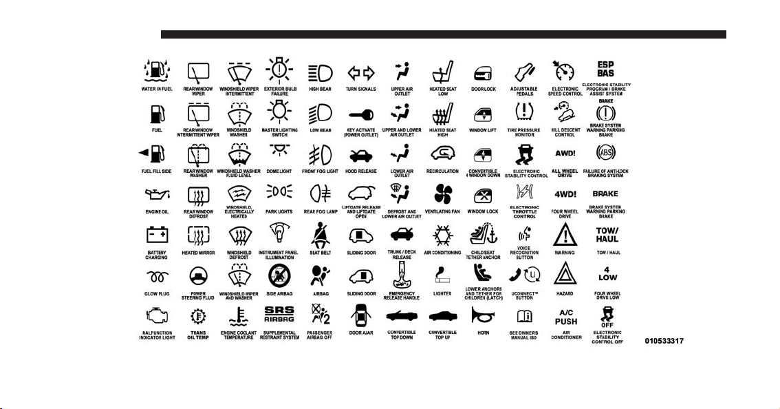
Consult the following table for a description of the
symbols that may be used on your vehicle or throughout
this Owner’s Manual:
1
6 INTRODUCTION

WARNINGS AND CAUTIONS
This Owner’s Manual contains WARNINGS against
operating procedures that could result in a collision or
bodily injury. It also contains CAUTIONS against procedures that could result in damage to your vehicle. If you
do not read this entire Owner’s Manual, you may miss
important information. Observe all Warnings and Cautions.
VEHICLE MODIFICATIONS/ALTERATIONS
WARNING!
Any modifications or alterations to this vehicle could
seriously affect its roadworthiness and safety and
may lead to a collision resulting in serious injury or
death.
INTRODUCTION 7
ROLLOVER WARNING
Utility vehicles have a significantly higher rollover rate
than other types of vehicles. This vehicle has a higher
ground clearance and a higher center of gravity than
many passenger vehicles. It is capable of performing
better in a wide variety of off-road applications. Driven
in an unsafe manner, all vehicles can go out of control.
Because of the higher center of gravity, if this vehicle is
out of control it may roll over while some other vehicles
may not.
1

8 INTRODUCTION
Do not attempt sharp turns, abrupt maneuvers, or other
unsafe driving actions that can cause loss of vehicle
control. Failure to operate this vehicle safely may result
in a collision, rollover of the vehicle, and severe or fatal
injury. Drive carefully.
Rollover Warning Label
Failure to use the driver and passenger seat belts provided is a major cause of severe or fatal injury. In fact, the
U.S. government notes that the universal use of existing
seat belts could cut the highway death toll by 10,000 or
more each year and could reduce disabling injuries by
two million annually. In a rollover crash, an unbelted
person is significantly more likely to die than a person
wearing a seat belt. Always buckle up.

CUSTOMER ASSISTANCE
CONTENTS
䡵 SUGGESTIONS FOR OBTAINING SERVICE
FOR YOUR VEHICLE ………………..11
2
▫ Customer Assistance For The Hearing Or
Speech Impaired (TDD/TTY) …………..13
▫ Prepare For The Appointment ………….11
▫ Prepare A List …………………….11
▫ Be Reasonable With Requests …………..11
䡵 IF YOU NEED ASSISTANCE ……………11
▫ FCA US LLC Customer Center ………….12
▫ FCA Canada Inc. Customer Center ……….12
▫ In Mexico Contact ………………….13
▫ Puerto Rico And U.S. Virgin Islands ………13
▫ Service Contract …………………..13
䡵 WARRANTY INFORMATION …………..15
䡵 REPORTING SAFETY DEFECTS ………….15
▫ In The 50 United States And Washington, D.C.. .15
▫ In Canada ………………………15
䡵 PUBLICATION ORDER FORMS ………….16

10 CUSTOMER ASSISTANCE
䡵 DEPARTMENT OF TRANSPORTATION
UNIFORM TIRE QUALITY GRADES ………17
▫ Treadwear ………………………17
▫ Traction Grades……………………17
▫ Temperature Grades ………………..18

SUGGESTIONS FOR OBTAINING SERVICE FOR
YOUR VEHICLE
Prepare For The Appointment
If you are having warranty work done, be sure to have
the right papers with you. Take your warranty folder. All
work to be performed may not be covered by the
warranty. Discuss additional charges with the service
manager. Keep a maintenance log of your vehicle’s
service history. This can often provide a clue to the
current problem.
Prepare A List
Make a written list of your vehicle’s problems or the
specific work you want done. If you’ve had an accident
or work done that is not on your maintenance log, let the
service advisor know.
CUSTOMER ASSISTANCE 11
Be Reasonable With Requests
If you list a number of items and you must have your
vehicle by the end of the day, discuss the situation with
the service advisor and list the items in order of priority.
At many authorized dealers, you may obtain a rental
vehicle at a minimal daily charge. If you need a rental, it
is advisable to make these arrangements when you call
for an appointment.
IF YOU NEED ASSISTANCE
The manufacturer and its authorized dealer are vitally
interested in your satisfaction. We want you to be happy
with our products and services.
Warranty service must be done by an authorized dealer.
We strongly recommend that you take the vehicle to an
authorized dealer. They know your vehicle the best, and
are most concerned that you get prompt and high quality
service. The manufacturer’s authorized dealer have the
2

12 CUSTOMER ASSISTANCE
facilities, factory-trained technicians, special tools, and
the latest information to ensure the vehicle is fixed
correctly and in a timely manner.
This is why you should always talk to an authorized
dealer service manager first. Most matters can be resolved with this process.
• If for some reason you are still not satisfied, talk to the
general manager or owner of the authorized dealer.
They want to know if you need assistance.
• If an authorized dealer is unable to resolve the concern, you may contact the manufacturer’s customer
center.
Any communication to the manufacturer’s customer center should include the following information:
• Owner’s name and address
• Owner’s telephone number (home and office)
• Authorized dealer name
• Vehicle Identification Number (VIN)
• Vehicle delivery date and mileage
FCA US LLC Customer Center
P.O. Box 21–8004
Auburn Hills, MI 48321–8004
Phone: (877) 426-5337
FCA Canada Inc. Customer Center
P.O. Box 1621
Windsor, Ontario N9A 4H6
Phone: (800) 465-2001 English / (800) 387-9983 French

In Mexico Contact
Av. Prolongacion Paseo de la Reforma, 1240
Sante Fe C.P. 05109
Mexico, D. F.
In Mexico City: 5081-7568
Outside Mexico City: 1-800-505-1300
Puerto Rico And U.S. Virgin Islands
Customer Service Chrysler International Services LLC
P.O. Box 191857
San Juan 00919-1857
Tel.: (787) 782-5757
Fax: (787) 782-3345
CUSTOMER ASSISTANCE 13
Customer Assistance For The Hearing Or Speech
Impaired (TDD/TTY)
To assist customers who have hearing difficulties, the
manufacturer has installed special TDD (Telecommunication Devices for the Deaf) equipment at its customer
center. Any hearing or speech impaired customer, who
has access to a TDD or a conventional teletypewriter
(TTY) in the United States, can communicate with the
manufacturer by dialing 1-800-380-CHRY.
Canadian residents with hearing difficulties that require
assistance can use the special needs relay service offered
by Bell Canada. For TTY teletypewriter users, dial 711
and for Voice callers, dial 1-800-855-0511 to connect with
a Bell Relay Service operator.
Service Contract
You may have purchased a service contract for a vehicle
to help protect you from the high cost of unexpected
repairs after the manufacturer’s New Vehicle Limited
2

14 CUSTOMER ASSISTANCE
Warranty expires. The manufacturer stands behind only
the manufacturer’s service contracts. If you purchased a
manufacturer’s service contract, you will receive Plan
Provisions and an Owner Identification Card in the mail
within three weeks of the vehicle delivery date. If you
have any questions about the service contract, call the
manufacturer’s Service Contract National Customer
Hotline at 1-800-521-9922 (Canadian residents, call (800)
465-2001 English / (800) 387-9983 French).
The manufacturer will not stand behind any service
contract that is not the manufacturer’s service contract. It
is not responsible for any service contract other than the
manufacturer’s service contract. If you purchased a service contract that is not a manufacturer’s service contract,
and you require service after the manufacturer’s New
Vehicle Limited Warranty expires, please refer to the
contract documents, and contact the person listed in
those documents.
We appreciate that you have made a major investment
when you purchased the vehicle. An authorized dealer
has also made a major investment in facilities, tools, and
training to assure that you are absolutely delighted with
the ownership experience. You will be pleased with their
sincere efforts to resolve any warranty issues or related
concerns.
WARNING!
Engine exhaust (internal combustion engines only),
some of its constituents, and certain vehicle components contain, or emit, chemicals known to the State
of California to cause cancer and birth defects, or
other reproductive harm. In addition, certain fluids
contained in vehicles and certain products of component wear contain, or emit, chemicals known to the
State of California to cause cancer and birth defects,
or other reproductive harm.

WARRANTY INFORMATION
See the Warranty Information Booklet, located on the
DVD, for the terms and provisions of FCA US LLC
warranties applicable to this vehicle and market.
REPORTING SAFETY DEFECTS
In The 50 United States And Washington, D.C.
If you believe that your vehicle has a defect that could
cause a crash or cause injury or death, you should
immediately inform the National Highway Traffic Safety
Administration (NHTSA) in addition to notifying the
manufacturer.
If NHTSA receives similar complaints, it may open an
investigation, and if it finds that a safety defect exists in
a group of vehicles, it may order a recall and remedy
campaign. However, NHTSA cannot become involved in
individual problems between you, your authorized
dealer, and the manufacturer.
CUSTOMER ASSISTANCE 15
To contact NHTSA, you may either call the Auto Safety
Hotline toll free at 1-888-327-4236 (TTY: 1-800-424-9153),
or go to http://www.safercar.gov; or write to: Administrator, NHTSA, 1200 New Jersey Avenue, SE., West
Building, Washington, D.C. 20590.
You can also obtain other information about motor
vehicle safety from http://www.safercar.gov.
In Canada
If you believe that your vehicle has a safety defect, you
should contact the Customer Service Department immediately. Canadian customers who wish to report a safety
defect to the Canadian government should contact Transport Canada, Motor Vehicle Defect Investigations and
Recalls at 1-800-333-0510 or go to http://www.tc.gc.ca/
roadsafety/
2

16 CUSTOMER ASSISTANCE
PUBLICATION ORDER FORMS
To order the following manuals, you may use either the
website or the phone numbers listed below. Visa, Mastercard, American Express, and Discover orders are accepted. If you prefer mailing your payment, please call
for an order form.
NOTE: A street address is required when ordering
manuals (no P.O. Boxes).
Service Manuals
These comprehensive Service Manuals provide the information that students and professional technicians need in
diagnosing/troubleshooting, problem solving, maintaining, servicing, and repairing FCA US LLC vehicles. A
complete working knowledge of the vehicle, system,
and/or components is written in straightforward language with illustrations, diagrams, and charts.
Diagnostic Procedure Manuals
Diagnostic Procedure Manuals are filled with diagrams,
charts and detailed illustrations. These practical manuals
make it easy for students and technicians to find and fix
problems on computer-controlled vehicle systems and
features. They show exactly how to find and correct
problems the first time, using step-by-step troubleshooting and drivability procedures, proven diagnostic tests
and a complete list of all tools and equipment.
Owner’s Manuals
These Owner’s Manuals have been prepared with the
assistance of service and engineering specialists to acquaint you with specific FCA US LLC vehicles. Included
are starting, operating, emergency and maintenance procedures as well as specifications, capabilities and safety
tips.

Call toll free at:
• 1-800-890-4038 (U.S.)
• 1-800-387-1143 (Canada)
Or
Visit us on the Worldwide Web at:
• www.techauthority.com
DEPARTMENT OF TRANSPORTATION UNIFORM
TIRE QUALITY GRADES
The following tire grading categories were established by
the National Highway Traffic Safety Administration. The
specific grade rating assigned by the tire’s manufacturer
in each category is shown on the sidewall of the tires on
your vehicle.
All passenger vehicle tires must conform to Federal
safety requirements in addition to these grades.
CUSTOMER ASSISTANCE 17
Treadwear
The Treadwear grade is a comparative rating, based on
the wear rate of the tire when tested under controlled
conditions on a specified government test course. For
example, a tire graded 150 would wear one and one-half
times as well on the government course as a tire graded
100. The relative performance of tires depends upon the
actual conditions of their use, however, and may depart
significantly from the norm due to variations in driving
habits, service practices, and differences in road characteristics and climate.
Traction Grades
The Traction grades, from highest to lowest, are AA, A, B,
and C. These grades represent the tire’s ability to stop on
wet pavement, as measured under controlled conditions
on specified government test surfaces of asphalt and
concrete. A tire marked C may have poor traction performance.
2
18 CUSTOMER ASSISTANCE
WARNING!
The traction grade assigned to this tire is based on
straight-ahead braking traction tests, and does not
include acceleration, cornering, hydroplaning, or
peak traction characteristics.
Temperature Grades
The temperature grades are A (the highest), B, and C,
representing the tire’s resistance to the generation of heat
and its ability to dissipate heat, when tested under
controlled conditions on a specified indoor laboratory
test wheel. Sustained high temperature can cause the
material of the tire to degenerate and reduce tire life, and
excessive temperature can lead to sudden tire failure. The
grade C corresponds to a level of performance, which all
passenger vehicle tires must meet under the Federal
Motor Vehicle Safety Standard No. 109. Grades B and A
represent higher levels of performance on the laboratory
test wheel, than the minimum required by law.
WARNING!
The temperature grade for this tire is established for
a tire that is properly inflated and not overloaded.
Excessive speed, under-inflation, or excessive loading, either separately or in combination, can cause
heat buildup and possible tire failure.

GRAPHICAL TABLE OF CONTENTS
CONTENTS
䡵 FRONT VIEW ……………………..20
▫ Front View (Trailhawk) ………………21
䡵 REAR VIEW ………………………22
▫ Rear View (Trailhawk) ……………….23
䡵 INSTRUMENT PANEL ………………..24
3
䡵 INTERIOR………………………..25
20 GRAPHICAL TABLE OF CONTENTS
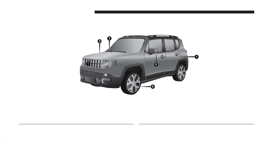
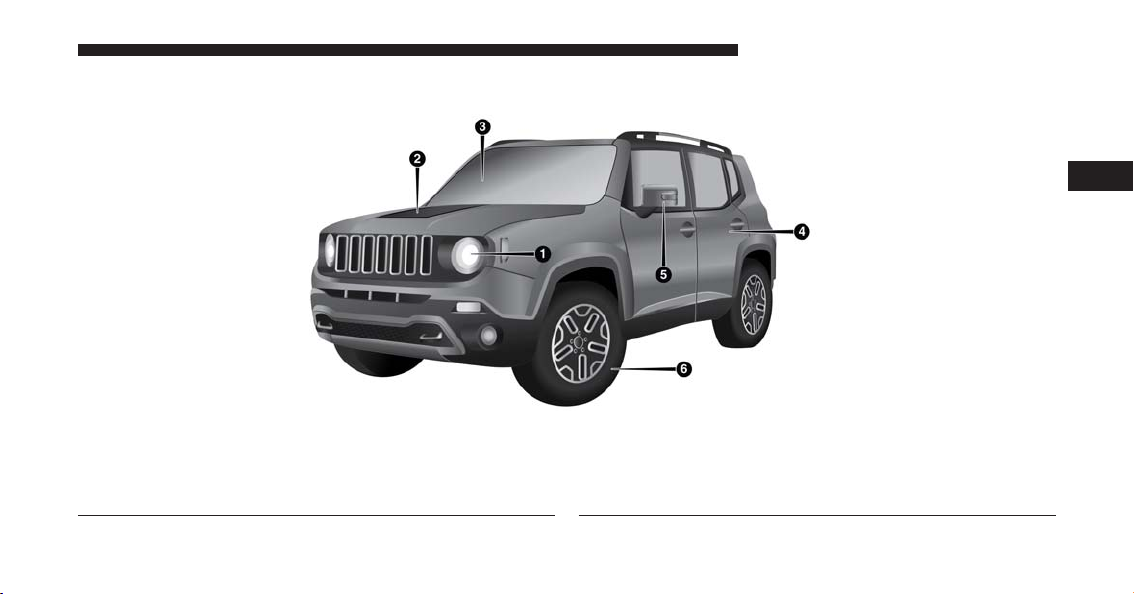
FRONT VIEW
1 — Headlights
2 — Engine Compartment
3 — Windshield
Front View
4 — Doors
5 — Exterior Mirrors
6 — Wheels
Front View (Trailhawk)
1 — Headlights
2 — Engine Compartment
3 — Windshield
GRAPHICAL TABLE OF CONTENTS 21
3
Front View (Trailhawk)
4 — Doors
5 — Exterior Mirrors
6 — Wheels
22 GRAPHICAL TABLE OF CONTENTS
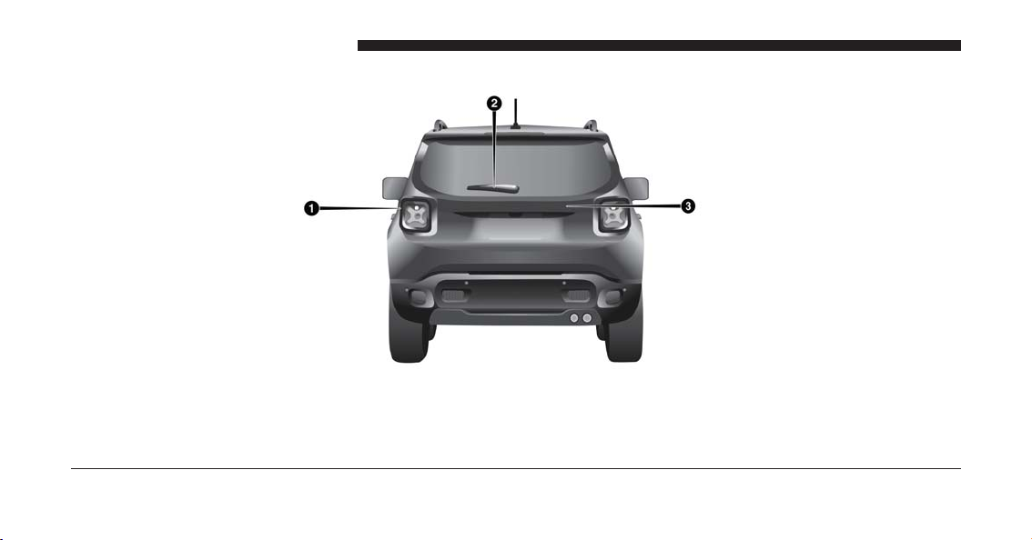
REAR VIEW
1 — Rear Lights
2 — Rear Windshield Wiper
3 — Liftgate
Rear View
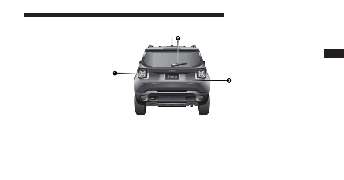
Rear View (Trailhawk)
1 — Rear Lights
2 — Rear Windshield Wiper
3 — Liftgate
GRAPHICAL TABLE OF CONTENTS 23
3
Rear View (Trailhawk)
24 GRAPHICAL TABLE OF CONTENTS
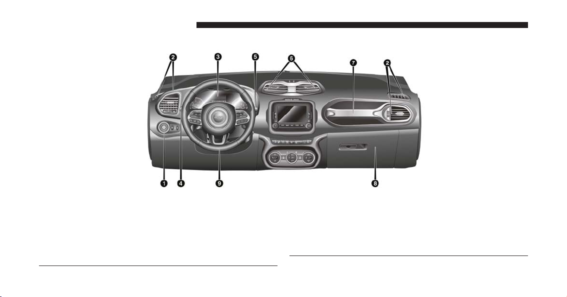
INSTRUMENT PANEL
1 — Headlight Switch
2—AirVents
3 — Instrument Cluster
4 — Multifunction Lever
5 — Windshield Wiper Lever
Instrument Panel
6—AirVents
7 — Hand Grip
8 — Glove Compartment
9 — Steering Wheel
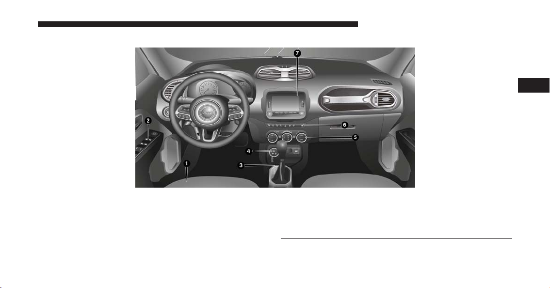
INTERIOR
1 — Seats
2 — Power Window Switches
3 — Transmission Shift Lever (Automatic/Manual options)
4 — Selec Terrain Mode Knob — If Equipped
GRAPHICAL TABLE OF CONTENTS 25
3
Interior Features
5 — Climate Controls
6 — Switch Panel
7 — Uconnect Radio


GETTING TO KNOW YOUR VEHICLE
CONTENTS
䡵 KEYS …………………………..31
▫ Key Fob With Remote Control ………….31
䡵 IGNITION SWITCH …………………41
▫ Operation ……………………….41
䡵 REMOTE STARTING SYSTEM —
IF EQUIPPED ……………………..45
▫ Remote Start Cancel Message —
If Equipped ……………………..46
▫ How To Use Remote Start …………….46
▫ To Enter Remote Start Mode……………47
▫ To Exit Remote Start Mode Without Driving
The Vehicle ……………………..48
▫ To Exit Remote Start Mode And Drive
The Vehicle………………………48
▫ Remote Start Comfort Systems —
If Equipped ……………………..48
▫ Remote Start Windshield Wiper De–Icer
Activation — If Equipped …………….49
▫ General Information ………………..49
䡵 SENTRY KEY ……………………..50
▫ General Information ………………..51
4

28 GETTING TO KNOW YOUR VEHICLE
䡵 VEHICLE SECURITY ALARM …………..51
▫ Rear Seats……………………….72
▫ To Arm The System ………………..52
▫ To Disarm The System ……………….53
▫ Disabling ……………………….54
䡵 DOORS …………………………54
▫ Manual Door Locks …………………54
▫ Central Lock/Unlock………………..56
▫ Keyless Enter-N-Go ………………..58
▫ Child Locks ……………………..65
䡵 SEATS ………………………….66
▫ Manual Front Seats …………………67
▫ Power Adjustment (Front) — If Equipped …..69
▫ Heated Seats — If Equipped……………71
䡵 HEAD RESTRAINTS …………………78
▫ Front Head Restraints ……………….79
▫ Rear Head Restraints ………………..80
䡵 STEERING WHEEL ………………….81
▫ Tilt/Telescoping Steering Column ………..81
▫ Heated Steering Wheel — If Equipped …….82
䡵 MIRRORS ………………………..83
▫ Inside Day/Night Mirror …………….83
▫ Auto Dimming Mirror — If Equipped ……..84
▫ Outside Mirrors …………………..85
▫ Heated Mirrors — If Equipped …………87

䡵 BLIND SPOT MONITORING (BSM) —
IF EQUIPPED ……………………..87
▫ Rear Cross Path (RCP) ………………93
▫ Mode Of Operation …………………94
▫ Blind Spot Monitoring Fault Warnings …….95
▫ General Information ………………..96
䡵 EXTERIOR LIGHTS ………………….97
▫ Headlights ………………………97
▫ Automatic Lighting — If Equipped ………98
▫ Daytime Running Lights (DRL) —
If Equipped ……………………..98
▫ Front Fog Lights — If Equipped ………..99
▫ Parking Lights ……………………99
▫ Headlight Delay …………………..99
GETTING TO KNOW YOUR VEHICLE 29
▫ Flash-To-Pass ……………………100
▫ High Beams …………………….101
▫ Turn Signals …………………….101
䡵 INTERIOR LIGHTS …………………102
▫ Front Lights …………………….102
▫ Interior Lights Dimmer Switch …………107
䡵 WIPERS AND WASHERS ……………..108
▫ Front Wiper Operation ………………108
▫ Rear Wiper Operation ………………111
▫ Windshield Wiper De-Icer — If Equipped ….113
䡵 WINDOWS ………………………114
▫ Power Windows ………………….114
4

30 GETTING TO KNOW YOUR VEHICLE
䡵 CLIMATE CONTROLS ……………….117
▫ Air Outlet And Diffuser Locations —
Passenger Compartment ……………..117
▫ Manual Climate Controls — If Equipped …..119
▫ Automatic Climate Controls — If Equipped . .123
䡵 MY SKY SUN ROOF — IF EQUIPPED ……..136
▫ Removable Roof — IF Equipped ……….136
▫ Power My Sky — If Equipped …………137
▫ Removing And Installing Panels ………..139
▫ Bag For Housing Panels — If Equipped ……145
▫ Emergency Open/Close ……………..148
䡵 HOOD …………………………150
▫ Closing………………………..155
▫ Cargo Area Features………………..156
䡵 INTERNAL EQUIPMENT ……………..163
▫ Glove Compartment ……………….163
▫ Sun Visors ……………………..164
▫ Power Outlets …………………..166
▫ Power Inverter — If Equipped …………168
▫ Cigar Lighter — Optional…………….169
▫ Ashtray — Optional………………..170
▫ Front Armrest …………………..171
▫ Cupholders …………………….172
▫ Handle Grip …………………….173
䡵 LIFTGATE ………………………152
▫ Opening ……………………….152
䡵 ROOF LUGGAGE RACK — IF EQUIPPED . . . .174

KEYS
Your vehicle uses either a key start ignition system or
keyless ignition system. The key start ignition system
consists of a Key Fob with a Remote Keyless Entry (RKE)
transmitter and an Ignition Node Module (IGNM). The
keyless ignition system consists of a Key Fob with
Remote Keyless Entry (RKE) transmitter and a Keyless
Ignition Node (KIN).
Key Fob With Remote Control
The Key Fob with Remote Control contains a Remote
Keyless Entry (RKE) transmitter. The RKE system allows
you to lock or unlock the doors and liftgate or activate the
Panic Alarm from distances up to approximately 66 ft (20
m) using a handheld Key Fob with a RKE transmitter.
The RKE transmitter does not need to be pointed at the
vehicle to activate the system.
NOTE: In the ON/RUN position, the LOCK button is
disabled. Only the UNLOCK button is enabled.
GETTING TO KNOW YOUR VEHICLE 31
Vehicles With Keyless Enter-N-Go
4
Keyless Enter-N-Go Key Fob

32 GETTING TO KNOW YOUR VEHICLE
Keyless Enter-N-Go Key Fob Emergency Key Release
A — Emergency Key Release Button
B — Emergency Key
Key Fob With Remote Control And Integrated Vehicle
Key
The Key Fob With Remote Control contains the RKE
transmitter with an integrated vehicle key. To use the
vehicle key, simply push the vehicle key release button.

GETTING TO KNOW YOUR VEHICLE 33
This device complies with Part 15 of the FCC Rules and
with Industry Canada licence-exempt RSS standard(s).
Operation is subject to the following two conditions:
1. This device may not cause harmful interference, and
Integrated Vehicle Key
1 — Vehicle Key
2 — Vehicle Key Release Button
General Information
The following regulatory statement applies to all radio
frequency (RF) devices equipped in this vehicle:
2. This device must accept any interference received,
including interference that may cause undesired operation.
NOTE: Changes or modifications not expressly approved
by the party responsible for compliance could void the
user’s authority to operate the equipment.
To Unlock The Doors And Liftgate
The driver ’s door may be unlocked by inserting the
vehicle key into the exterior driver’s door lock cylinder.
To unlock all the doors, push the interior door unlock
button on the door panel.
4

34 GETTING TO KNOW YOUR VEHICLE
Push and release the UNLOCK button on the RKE
transmitter once to unlock the driver’s door or twice
within five seconds to unlock all doors and the liftgate.
The turn signal lights will flash to acknowledge the
unlock signal. The illuminated entry system will also
turn on.
1st Push Of Key Fob Unlocks
This feature lets you program the system to unlock either
the driver’s door or all doors on the first push of the
UNLOCK button on the RKE transmitter. To change the
current setting, refer to “Uconnect SETTINGS” in “Multimedia” for further information.
NOTE: If the vehicle is equipped with Passive Entry,
refer to “Keyless Enter-N-Go” in “Getting To Know Your
Vehicle” for further information.
To Lock The Doors And Liftgate
If equipped, the doors may be locked by inserting the
vehicle key into the exterior driver’s door lock cylinder.
Push and release the LOCK button on the RKE transmitter to lock all doors and liftgate. The turn signal lights
will flash and the horn will chirp to acknowledge the
signal. Settings in radio can change to lights only, chirp
only, or both.
If the vehicle is equipped with Passive Entry, refer to
“Keyless Enter-N-Go” in “Getting To Know Your Vehicle” for further information.
Key Fob With Remote Control And Integrated Vehicle
Key
If one or more doors are open, or the liftgate is open, the
doors will lock. This is signaled by a quick flash of the
turn signals.

Vehicles With Keyless Enter-N-Go
If one or more doors are open, or the liftgate is open, the
doors will lock. The doors will unlock again only if the
key is inside the passenger compartment.
NOTE:
• The current setting can be changed within the Electronic Vehicle Information Center (EVIC) menu or in
the Uconnect Settings so that the system will allow/
inhibit the ability to lock the doors when one or more
of them are open.
• For more information, refer to “Multi-Functional Display (EVIC)” in “Getting To Know Your Instrument
Panel,” subsection “Electronic Vehicle Information
Center (EVIC)/ Driver Information Display (DID),” or
“Uconnect Settings” in “Multimedia.”
GETTING TO KNOW YOUR VEHICLE 35
Replacing The Battery In The Key Fob With
Remote Control
The recommended replacement battery is one CR2032
battery.
NOTE:
• Perchlorate Material — special handling may apply.
See www.dtsc.ca.gov/hazardouswaste/perchlorate
• Do not touch the battery terminals that are on the back
housing or the printed circuit board.
4

36 GETTING TO KNOW YOUR VEHICLE
Key Fob With Remote Control
1. Separating RKE halves requires screw removal (if
equipped) and gently prying the two halves of the
RKE transmitter apart using a screwdriver or similar
tool. Make sure not to damage the seal during removal.
Integrated Vehicle Key Battery Removal
A — RKE Transmitter

2. Remove the battery by turning the back cover over
(battery facing downward) and tapping it lightly on a
solid surface such as a table or similar surface. Then,
replace the battery.
When replacing the battery, match the + sign on the
battery to the + sign on the inside of the battery clip,
located on the back cover. Avoid touching the new
battery with your fingers. Skin oils may cause battery
deterioration. If you touch a battery, clean it with rubbing
alcohol.
GETTING TO KNOW YOUR VEHICLE 37
4
Integrated Vehicle Key Battery Removal
B — Battery

38 GETTING TO KNOW YOUR VEHICLE
Separating Keyless Enter-N-Go Transmitter Case
1. Remove the emergency key by sliding the mechanical
latch on the back of the RKE transmitter sideways
with your thumb. Then, pull the key out with your
other hand.
2. Separating RKE halves requires screw removal (if
equipped) and gently prying the two halves of the
RKE transmitter apart with the emergency key. Make
sure not to damage the seal during removal.
Separating Keyless Enter-N-Go Transmitter Case
A — RKE Transmitter

3. Remove the battery by turning the back cover over
(battery facing downward) and tapping it lightly on a
solid surface such as a table or similar surface. Then,
replace the battery.
When replacing the battery, match the + sign on the
battery to the + sign on the inside of the battery clip,
located on the back cover. Avoid touching the new
battery with your fingers. Skin oils may cause battery
deterioration. If you touch a battery, clean it with rubbing
alcohol.
GETTING TO KNOW YOUR VEHICLE 39
4
Keyless Enter-N-Go Battery Replacement
B — Battery
4. To assemble the RKE transmitter case, snap the two
halves together and insert the emergency key.

40 GETTING TO KNOW YOUR VEHICLE
Programming Additional Transmitters
Programming Key Fobs or RKE transmitters may be
performed at an authorized dealer.
Request For Additional Key Fobs
NOTE: Only Key Fobs that are programmed to the
vehicle electronics can be used to start and operate the
vehicle. Once a Key Fob is programmed to a vehicle, it
cannot be programmed to any other vehicle.
CAUTION!
• Always remove the Key Fobs from the vehicle and
lock all doors when leaving the vehicle unattended.
• For vehicles equipped with Keyless Enter-N-Go,
always remember to place the ignition in the OFF
position.
At the time of purchase, the original owner is provided
with a four-digit Personal Identification Number (PIN).
Keep the PIN in a secure location. This number is
required for authorized dealer replacement of Key Fobs.
Duplication of Key Fobs may be performed at an authorized dealer. This procedure consists of programming a
blank Key Fob to the vehicle electronics. A blank Key Fob
is one that has never been programmed.
NOTE: When having the Sentry Key Immobilizer System
serviced, bring all vehicle keys with you to an authorized
dealer.

IGNITION SWITCH
Operation
Your vehicle uses either a key start ignition system or
keyless ignition system. The key start ignition system
consists of a Key Fob with a Remote Keyless Entry (RKE)
transmitter and an Ignition Node Module (IGNM). The
keyless ignition system consists of a Key Fob with
Remote Keyless Entry (RKE) transmitter and a Keyless
Ignition Node (KIN).
Models With Integrated Vehicle Key
The Ignition Node Module (IGNM) operates similar to an
ignition switch. It has three operating positions, two with
detents and one that is spring-loaded. The detent positions are STOP/OFF, MAR/RUN, and AVV/START. The
AVV/START position is a spring-loaded momentary
contact position. When released from the AVV/START
position, the switch automatically returns to the MAR/
RUN position.
GETTING TO KNOW YOUR VEHICLE 41
4
Ignition Node Module (IGNM)
1 — STOP/OFF
• The engine is stopped.
• The key can be removed from the IGNM.
• The steering column can be locked (with the ignition
key removed).

42 GETTING TO KNOW YOUR VEHICLE
• Some electrical devices (e.g. power locks, alarm, etc.)
are still available.
2 — MAR/RUN
• Driving position.
• Electrical devices are available.
3 — AVV/START
• Start the engine.
The ignition switch is provided with a safety mechanism.
If the engine fails to start, the ignition should be returned
to the STOP/OFF position prior to repeating the starting
procedure.
On models equipped with an automatic transmission, the
ignition key is only removable when the shift lever is in
PARK (P).
Models With Keyless Enter-N-Go
This feature allows the driver to operate the ignition
switch with the push of a button as long as the Remote
Keyless Entry (RKE) transmitter is in the passenger
compartment.
The Keyless Ignition Node (KIN System) has three operating positions. The three positions are STOP, RUN, and
START.
NOTE: If the ignition switch does not change with the
push of a button, the RKE transmitter (Key Fob) may
have a low or dead battery. In this situation, a back up
method can be used to operate the ignition switch. Put
the nose side (side opposite of the emergency key) of the
Key Fob against the ENGINE START/STOP button and
push to operate the ignition switch.

START/STOP Button
GETTING TO KNOW YOUR VEHICLE 43
The KIN can be placed in the following positions:
STOP
• The engine is stopped.
• Some electrical devices (e.g. Central locking, alarm,
etc.) are still available.
RUN
• Driving position.
• All the electrical devices are available.
START
• Start the engine.
NOTE: The vehicle will not start if the FOBIK is located
inside the cargo area AND the liftgate is opened.
4

44 GETTING TO KNOW YOUR VEHICLE
WARNING!
• When leaving the vehicle, always remove the Key
Fob from the vehicle and lock your vehicle.
• Never leave children alone in a vehicle, or with
access to an unlocked vehicle.
• Allowing children to be in a vehicle unattended is
dangerous for a number of reasons. A child or
others could be seriously or fatally injured. Children should be warned not to touch the parking
brake, brake pedal or the gear selector.
• Do not leave the Key Fob in or near the vehicle, or
in a location accessible to children, and do not
leave the ignition of a vehicle equipped with
Keyless Enter-N-Go in the MAR/RUN mode. A
child could operate power windows, other controls,
or move the vehicle.
(Continued)
WARNING! (Continued)
• Do not leave children or animals inside parked
vehicles in hot weather. Interior heat build-up may
cause serious injury or death.
CAUTION!
An unlocked car is an invitation to thieves. Always
remove key from the ignition and lock all doors
when leaving the vehicle unattended.
NOTE: For further information, refer to ⬙Starting the
Engine,⬙ in ⬙Starting And Operating.⬙

General Information
The following regulatory statement applies to all radio
frequency (RF) devices equipped in this vehicle:
This device complies with Part 15 of the FCC Rules and
with Industry Canada licence-exempt RSS standard(s).
Operation is subject to the following two conditions:
1. This device may not cause harmful interference, and
2. This device must accept any interference received,
including interference that may cause undesired operation.
GETTING TO KNOW YOUR VEHICLE 45
REMOTE STARTING SYSTEM — IF EQUIPPED
This system uses the Remote Keyless Entry
(RKE) transmitter to start the engine conveniently from outside the vehicle while still
maintaining security. The system has a range of
246 ft (75 m).
The Remote Starting System also activates the Climate
Control and (if equipped) the optional heated seats and
optional heated steering wheel depending on temperatures outside and inside the car.
4
NOTE: Changes or modifications not expressly approved
by the party responsible for compliance could void the
user’s authority to operate the equipment.
NOTE:
• The vehicle must be equipped with an automatic
transmission to be equipped with Remote Start.
• Obstructions between the vehicle and RKE transmitter
may reduce this range.

46 GETTING TO KNOW YOUR VEHICLE
Remote Start Cancel Message — If Equipped
The following messages will display in the instrument
cluster if the vehicle fails to remote start or exits remote
start prematurely:
• Remote Start Cancelled — Door Open
• Remote Start Cancelled — Hood Open
• Remote Start Cancelled — Fuel Low
• Remote Start Cancelled — Liftgate Open
• Remote Start Disabled — Start Vehicle To Reset
• Remote Start Cancelled — Too Cold
• Remote Start Cancelled — Time Expired
The message will stay active until the ignition is placed in
the MAR/RUN position.
How To Use Remote Start
All of the following conditions must be met before the
engine will remote start:
• Shift Lever in PARK
• Doors closed
• Hood closed
• Liftgate closed
• Hazard switch off
• Brake switch inactive (brake pedal not pushed)
• Battery at an acceptable charge level
• RKE PANIC button not pushed
• System not disabled from previous remote start event
• Vehicle alarm system indicator flashing

• Ignition in STOP/OFF position
• Fuel level meets minimum requirement
WARNING!
• Do not start or run an engine in a closed garage or
confined area. Exhaust gas contains Carbon Monoxide (CO) which is odorless and colorless. Carbon
Monoxide is poisonous and can cause serious injury or death when inhaled.
• Keep Remote Keyless Entry (RKE) transmitters
away from children. Operation of the Remote Start
System, windows, door locks or other controls
could cause serious injury or death.
GETTING TO KNOW YOUR VEHICLE 47
To Enter Remote Start Mode
Push and release the REMOTE START button
on the RKE transmitter twice within five seconds. The vehicle doors will lock, the turn
signals will flash, and the horn will chirp twice.
Then, the engine will start, and the vehicle will remain in
the Remote Start mode for a 15-minute cycle.
NOTE:
• If an engine fault is present or fuel level is low, the
vehicle will start and then shut down in 10 seconds.
• The park lamps will turn on and remain on during
Remote Start mode.
• For security, power window operation is disabled
when the vehicle is in the Remote Start mode.
4

48 GETTING TO KNOW YOUR VEHICLE
To Exit Remote Start Mode Without Driving The
Vehicle
Push and release the REMOTE START button one time or
allow the engine to run for the entire 15-minute cycle.
NOTE: To avoid unintentional shutdowns, the system
will disable the one time push of the REMOTE START
button for two seconds after receiving a valid Remote
Start request.
To Exit Remote Start Mode And Drive The Vehicle
Before the end of 15-minute cycle, push and release the
UNLOCK button on the RKE transmitter to unlock the
doors and disarm the Vehicle Security Alarm (if
equipped). Then, prior to the end of the 15-minute cycle,
for vehicles equipped with the Keyless Enter-N-Go feature push and release the START/STOP button; for
vehicles not equipped with Keyless Enter-N-Go feature
put the key in RUN position.
NOTE: For vehicles equipped with the Keyless EnterN-Go feature, the message “Remote Start Active — Push
Start Button” will display in the Electronic Vehicle Information Center (EVIC) or the Driver Information Dispay
(DID) until you push the START button.
NOTE: For vehicles not equipped with the Keyless
Enter-N-Go feature, the message “Remote Start Active —
Key to RUN” will display in the Electronic Vehicle
Information Center (EVIC) until you put the key in RUN
position.
Remote Start Comfort Systems — If Equipped
When Remote Start is activated, the heated steering
wheel and driver heated seat features will automatically
turn on in cold weather. These features will stay on
through the duration of Remote Start or until the ignition
switch is cycled to the MAR/RUN position.

NOTE: The Remote Start Comfort System can be activated and deactivated through the Uconnect Settings. For
more information on Remote Start Comfort System operation, refer to “Uconnect Settings” in “Multimedia.”
Remote Start Windshield Wiper De–Icer
Activation — If Equipped
When Remote Start is active and the outside ambient
temperature is less than 40° F (4.4° C), the Windshield
Wiper De-Icer will be enabled. Exiting Remote Start will
resume previous operation, except if the Windshield
Wiper De-Icer is active. The Windshield Wiper De-Icer
timer and operation will continue.
GETTING TO KNOW YOUR VEHICLE 49
General Information
The following regulatory statement applies to all radio
frequency (RF) devices equipped in this vehicle:
This device complies with Part 15 of the FCC Rules and
with Industry Canada licence-exempt RSS standard(s).
Operation is subject to the following two conditions:
1. This device may not cause harmful interference, and
2. This device must accept any interference received,
including interference that may cause undesired operation.
NOTE: Changes or modifications not expressly approved
by the party responsible for compliance could void the
user’s authority to operate the equipment.
4

50 GETTING TO KNOW YOUR VEHICLE
SENTRY KEY
The Sentry Key Immobilizer system prevents unauthorized vehicle operation by disabling the engine. The
system does not need to be armed or activated. Operation
is automatic, regardless of whether the vehicle is locked
or unlocked.
The system uses a Key Fob with a factory-mated Remote
Keyless Entry (RKE) transmitter, a Keyless Push Button
Ignition, and a RF receiver to prevent unauthorized
vehicle operation. Therefore, only Key Fobs that are
programmed to the vehicle can be used to start and
operate the vehicle. The system will not allow the engine
to crank if an invalid Key Fob tries to start the engine.
After placing the ignition to the ON/RUN position, if
there is a problem with the system, the Vehicle Security
Light will turn on. This condition will result in the engine
being shut off after two seconds.
Should this occur, have the vehicle serviced as soon as
possible by an authorized dealer.
CAUTION!
• Do not make modifications or alterations to the
immobilizer system. Modifications or alterations to
the immobilization system may result in a loss of
security protection.
• The Sentry Key Immobilizer system is not compatible with some aftermarket remote starting systems. Use of these systems may result in vehicle
starting problems and loss of security protection.

General Information
The following regulatory statement applies to all radio
frequency (RF) devices equipped in this vehicle:
This device complies with Part 15 of the FCC Rules and
with Industry Canada licence-exempt RSS standard(s).
Operation is subject to the following two conditions:
1. This device may not cause harmful interference, and
2. This device must accept any interference received,
including interference that may cause undesired operation.
NOTE: Changes or modifications not expressly approved
by the party responsible for compliance could void the
user’s authority to operate the equipment.
GETTING TO KNOW YOUR VEHICLE 51
VEHICLE SECURITY ALARM
The Vehicle Security Alarm monitors the vehicle doors
for unauthorized entry and if the ignition switch is cycled
to the ON/RUN position without a valid key. While the
Vehicle Security Alarm is armed, interior switches for
door locks and liftgate release are disabled.
If something triggers the alarm, the Vehicle Security
Alarm will provide the following audible and visible
signals:
• Horn will pulse.
• Park lamps and/or turn signals will flash.
4

52 GETTING TO KNOW YOUR VEHICLE
• Vehicle Security Light in the instrument cluster will
flash.
Vehicle Security Light Location
A — Vehicle Security Light
To Arm The System
Follow these steps to arm the Vehicle Security Alarm:
1. Make sure the vehicles ignition is cycled to the STOP/
OFF position (refer to ⬙Starting The Engine⬙ in ⬙Starting And Operating⬙ for further information).
• For vehicles equipped with Keyless Enter-N-Go,
make sure the vehicle ignition system is OFF.
• For vehicles not equipped with Keyless Enter-N-Go,
make sure the vehicle ignition system is STOP/OFF,
and the key is physically removed from the ignition.
2. Perform one of the following methods to lock the
vehicle:
• Push LOCK on the interior power door lock switch
with the driver and/or passenger door open.
• Push the LOCK button on the exterior Passive Entry
Door Handle with a valid Key Fob available in the

same exterior zone (for further information, refer to
⬙Keyless Enter-N-Go⬙ in ⬙Getting To Know Your
Vehicle”).
• Push the LOCK button on the Remote Keyless Entry
(RKE) transmitter.
3. If any doors are open, close them.
NOTE:
• If a second chime is heard after approximately four
seconds from arming the alarm, disarm the alarm by
pressing the UNLOCK button. Check for the correct
closure of doors and liftgate, then reactivate the
system by following steps 1 and 2.
• If a second chime is heard after approximately four
seconds from arming the alarm, even with the doors
and liftgate properly closed, a fault may have occurred during the arming operation. If this occurs,
contact your authorized dealer.
GETTING TO KNOW YOUR VEHICLE 53
To Disarm The System
The Vehicle Security Alarm can be disarmed using any of
the following methods:
• Push the UNLOCK button on the Remote Keyless
Entry (RKE) transmitter.
• Grasp the Passive Entry Unlock Door Handle with a
valid Key Fob available in the same exterior zone (if
equipped). Refer to ⬙Keyless Enter-N-Go⬙ in ⬙Getting
To Know Your Vehicle⬙ for further information.
• Cycle the vehicle ignition system out of the STOP/OFF
position.
– For vehicles equipped with Keyless Enter-N-Go,
push the Keyless Enter-N-Go START/STOP button
(requires at least one valid Key Fob in the vehicle).
– For vehicles not equipped with Keyless Enter-N-Go,
insert a valid key into the ignition switch and turn
the key to the MAR/RUN position.
4

54 GETTING TO KNOW YOUR VEHICLE
NOTE:
• The driver’s door key cylinder cannot arm or disarm
the Vehicle Security Alarm.
• When the Vehicle Security Alarm is armed, the interior
power door lock switches will not unlock the doors.
The Vehicle Security Alarm is designed to protect your
vehicle. However, you can create conditions where the
system will give you a false alarm. If one of the previously described arming sequences has occurred, the
Vehicle Security Alarm will arm regardless of whether
you are in the vehicle or not. If you remain in the vehicle
and open a door, the alarm will sound. If this occurs,
disarm the Vehicle Security Alarm.
If the Vehicle Security Alarm is armed and the battery
becomes disconnected, the Vehicle Security Alarm will
remain armed when the battery is reconnected.
Disabling
To completely disable the alarm (e.g. in the case of long
inactivity of the car), lock the doors by turning the vehicle
key in the exterior door lock cylinder.
NOTE: If the batteries in the RKE transmitter discharge
in the event of a failure to the system, or to switch off the
alarm, place the ignition in the MAR/RUN position.
DOORS
Manual Door Locks
To lock each door, rotate the door lock button on each
door trim panel forward. To unlock the doors, pull the
inside door handle to the first detent or rotate the door
lock button until the lock symbol is no longer visible.
If the lock symbol is visible when the door is shut, the
door will lock. Therefore, make sure the Key Fob is not
inside the vehicle before closing the door.

Locking/Unlocking Doors From Outside
With the doors closed, insert the key blade into the driver
exterior door lock cylinder and turn to the right to lock
the driver’s door.
To unlock the driver’s door, insert the key blade into the
driver exterior door lock cylinder and turn to the left to
unlock the driver’s door.
GETTING TO KNOW YOUR VEHICLE 55
4
Manual Door Lock
NOTE: The manual lock knob unlocks each individual
door separately.

56 GETTING TO KNOW YOUR VEHICLE
WARNING!
• For personal security and safety in the event of a
collision, lock the vehicle doors before you drive as
well as when you park and leave the vehicle.
• When leaving the vehicle, always remove the Key
Fob from the vehicle and lock your vehicle. Unsupervised use of vehicle equipment may cause severe personal injuries or death.
• Never leave children alone in a vehicle, or with
access to an unlocked vehicle. Allowing children to
be in a vehicle unattended is dangerous for a
number of reasons. A child or others could be
seriously or fatally injured. Children should be
warned not to touch the parking brake, brake pedal
or the gear selector.
• Do not leave the Key Fob in or near the vehicle, or
in a location accessible to children, and do not
(Continued)
WARNING! (Continued)
leave the ignition of a vehicle equipped with
Keyless Enter-N-Go in the RUN mode. A child
could operate power windows, other controls, or
move the vehicle.
Central Lock/Unlock
A power door lock switch is located on each of the front
door trim panels. This switch is used to lock or unlock the
doors and liftgate.
Locking/Unlocking From The Inside
Push the button on the driver or passenger door trim
panel to lock the doors.
With the doors locked, push the button to unlock the
doors.

Power Door Lock Switch
GETTING TO KNOW YOUR VEHICLE 57
The doors can also be locked and unlocked with the
Keyless Enter-N-Go (Passive Entry) system if equipped.
Refer to “Keyless Enter-N-Go” in “Getting To Know Your
Vehicle” for further information.
The power locks will continue to operate while the
ignition is in the MAR/RUN and STOP/OFF position. If
a door is open, and the ignition is in the MAR/RUN
position, a chime will sound as a reminder to remove the
key.
NOTE: If all of the doors are closed properly, the door
locks will lock automatically when the vehicle’s speed
exceeds 12 mph (20 km/h). Refer to “Uconnect SETTINGS” in “Multimedia” for further information.
4

58 GETTING TO KNOW YOUR VEHICLE
Keyless Enter-N-Go
The Passive Entry system is an enhancement to the
vehicle’s Remote Keyless Entry (RKE) system and a
feature of Keyless Enter-N-Go. This feature allows you to
lock and unlock the vehicle’s door(s) without having to
push the RKE transmitter LOCK or UNLOCK buttons.
NOTE:
• Passive Entry can be enabled or disabled. Refer to
“Uconnect SETTINGS” in “Multimedia” for further
information.
• If wearing gloves on your hands, or if it has been
raining on the Passive Entry door handle, the unlock
sensitivity can be affected, resulting in a slower response time.
• If the vehicle is unlocked by the Passive Entry Door
Handle, and no door is opened within 60 seconds, the
vehicle will re-lock and if equipped, the security alarm
will arm.
To Unlock From The Driver’s Side
With a valid Passive Entry RKE transmitter within 5 ft
(1.5 m) of the driver’s door handle, grab the front driver
door handle to unlock the driver’s door automatically.

Grab The Door Handle To Unlock
NOTE: If “Unlock All Doors 1st Press” is programmed,
all doors will unlock when you grab hold of the front
driver’s door handle. To select between “Unlock Driver
Door 1st Press” and “Unlock All Doors 1st Press,” refer to
“Uconnect SETTINGS” in “Multimedia” for further information.
GETTING TO KNOW YOUR VEHICLE 59
To Unlock From The Passenger Side
With a valid Passive Entry RKE transmitter within 5 ft
(1.5 m) of the passenger door handle, grab the front
passenger door handle to unlock all four doors and the
liftgate automatically.
NOTE: All doors will unlock when the front passenger
door handle is grabbed regardless of the driver’s door
unlock preference setting (“Unlock Driver Door 1st
Press” or “Unlock All Doors 1st Press”).
To Lock The Vehicle’s Doors And Liftgate
With one of the vehicle’s Passive Entry RKE transmitters
within 5 ft (1.5 m) of the driver or passenger front door
handles, push the door handle LOCK button to lock all
four doors.
4

60 GETTING TO KNOW YOUR VEHICLE
Do NOT grab the door handle when pushing the door
handle LOCK button. This could unlock the door(s).
Push The Door Handle Button To Lock
DO NOT Grab The Door Handle When Locking
NOTE: The Passive Entry system will not operate if the
RKE transmitter battery is dead.
The vehicle doors can also be locked by using the lock
button located on the vehicle’s interior door panel.

Preventing Inadvertent Locking Of Passive Entry RKE
Transmitter In Vehicle (FOBIK-Safe)
To minimize the possibility of unintentionally locking a
Passive Entry RKE transmitter inside your vehicle, the
Passive Entry system is equipped with an automatic door
unlock feature which will function if the ignition switch
is in the OFF position.
FOBIK-Safe only executes in vehicles with Passive Entry.
There are three situations that trigger a FOBIK-Safe
search in any Passive Entry vehicle:
1. A lock request is made by a valid Passive Entry RKE
transmitter while a door is open.
2. A lock request is made by the Passive Entry door
handle while a door is open.
3. A lock request is made by the door panel switch while
the door is open.
GETTING TO KNOW YOUR VEHICLE 61
When any of these situations occur, after all open doors
are shut, the FOBIK-Safe search will be executed. If it
finds a Passive Entry RKE transmitter inside the car, and
it does not find any Passive Entry RKE transmitters
outside the car, then the car will unlock and alert the
customer.
4
NOTE: The vehicle will only unlock the doors when a
valid Passive Entry RKE transmitter is detected inside the
vehicle, and no valid Passive Entry RKE transmitter is
detected outside the vehicle. The vehicle will not unlock
the doors when any of the following conditions are met:
• The doors are manually locked using the door lock
knobs.
• There is a valid Passive Entry RKE transmitter outside
the vehicle and within 5 ft (1.5 m) of either Passive
Entry door handle.

62 GETTING TO KNOW YOUR VEHICLE
To Unlock/Enter The Liftgate
The liftgate Passive Entry unlock feature is built into the
electronic liftgate release. With a valid Passive Entry RKE
transmitter within 3 ft (1.0 m) of the liftgate, push the
Electronic Liftgate release to open with one fluid motion.
To Lock The Liftgate
With a valid Passive Entry RKE transmitter within 3 ft
(1.0 m) of the liftgate, push the Passive Entry LOCK
button located to the right of electronic liftgate release.
NOTE: The liftgate Passive Entry lock button will lock
the liftgate and the doors. The liftgate unlock feature is
built into the Electronic Liftgate release.
Liftgate Release/Passive Entry
A — Electronic Liftgate Release/Liftgate Passive Entry Location
B — Electronic Liftgate Lock/Liftgate Passive Lock Location

NOTE: If “Unlock All Doors 1st Press” is programmed in
EVIC/DID, if equipped, only the liftgate will unlock
when you push the Electronic Release. If ⬙Unlock Driver
Door 1st Press⬙ is programmed in Uconnect, the liftgate
will unlock when you push the electronic lock/unlock
button on the liftgate. For further information, refer to
“Uconnect SETTINGS” in “Multimedia.”
Emergency Unlocking Driver Door
If the Remote Keyless Entry (RKE) transmitter battery is
low or dead, the emergency key can be used to unlock the
driver side door lock cylinder.
To release the emergency key, proceed as follows:
1. Slide the emergency key release button to the side.
2. Remove the emergency key from the Key Fob with
Remote Control housing.
GETTING TO KNOW YOUR VEHICLE 63
4
Emergency Key Release
1 — Emergency Key Release Button
2 — Emergency Key
NOTE: The Emergency Key can be inserted into the door
lock cylinder from either direction.

64 GETTING TO KNOW YOUR VEHICLE
WARNING!
• Never leave children alone in a vehicle, or with
access to an unlocked vehicle. Allowing children to
be in a vehicle unattended is dangerous for a
number of reasons. A child or others could be
severely injured or killed. Children should be
warned not to touch the parking brake, brake
pedal, or the gear selector. Do not leave the Key Fob
in or near the vehicle, or in a location accessible to
children, and do not leave the ignition of a vehicle
equipped with Keyless Enter- N-Go in the MAR/
RUN mode. A child could start the vehicle, operate
power windows, other controls, or move the vehicle.
• Do not leave children or animals inside parked
vehicles in hot weather. Interior heat build-up may
cause them to be severely injured or killed.
General Information
The following regulatory statement applies to all radio
frequency (RF) devices equipped in this vehicle:
This device complies with Part 15 of the FCC Rules and
with Industry Canada licence-exempt RSS standard(s).
Operation is subject to the following two conditions:
1. This device may not cause harmful interference, and
2. This device must accept any interference received,
including interference that may cause undesired operation.
NOTE: Changes or modifications not expressly approved
by the party responsible for compliance could void the
user’s authority to operate the equipment.

Child Locks
To provide a safer environment for small children riding
in the rear seats, the rear doors are equipped with a
Child-Protection Door Lock system.
To use the system, open each rear door, use a flat blade
screwdriver (or ignition key) and rotate the dial to the
LOCK or UNLOCK position. When the system on a door
is engaged, that door can only be opened by using the
outside door handle even if the inside door lock is in the
unlocked position.
GETTING TO KNOW YOUR VEHICLE 65
4
Child-Protection Door Lock Location

66 GETTING TO KNOW YOUR VEHICLE
NOTE:
• When the child lock system is engaged, the door can
only be opened by using the outside door handle even
though the inside door lock is in the unlocked position.
• After disengaging the Child-Protection Door Lock
system, always test the door from the inside to make
certain it is in the desired position.
• After engaging the Child-Protection Door Lock system, always test the door from the inside to make
certain it is in the desired position.
• For emergency exit with the system engaged, rotate
the lock button to the unlocked position, roll down the
window, and open the door with the outside door
handle.
WARNING!
Avoid trapping anyone in a vehicle in a collision.
Remember that the rear doors can only be opened
from the outside when the Child-Protection locks are
engaged.
SEATS
Seats are a part of the Occupant Restraint System of the
vehicle.
WARNING!
• It is dangerous to ride in a cargo area, inside or
outside of a vehicle. In a collision, people riding in
these areas are more likely to be seriously injured
or killed.
(Continued)

WARNING! (Continued)
• Do not allow people to ride in any area of your
vehicle that is not equipped with seats and seat
belts. In a collision, people riding in these areas are
more likely to be seriously injured or killed.
• Be sure everyone in your vehicle is in a seat and
using a seat belt properly.
GETTING TO KNOW YOUR VEHICLE 67
Manual Front Seats
4
Manual Seat Adjustment Levers
1 — Forward/Rearward Adjustment Bar
2 — Seat Height Adjustment Lever
3 — Recline Lever

68 GETTING TO KNOW YOUR VEHICLE
Manual Front Seat Forward/Rearward Adjustment
On models equipped with manual seats, the adjusting
bar is located at the front of the seats, near the floor.
While sitting in the seat, lift up on the bar and move the
seat forward or rearward. Release the bar once you have
reached the desired position. Then, using body pressure,
move forward and rearward on the seat to be sure that
the seat adjusters have latched.
WARNING!
• Adjusting a seat while the vehicle is moving is
dangerous. The sudden movement of the seat could
cause you to lose control. The seat belt might not be
adjusted properly and you could be injured. Adjust
the seat only while the vehicle is parked.
(Continued)
WARNING! (Continued)
• Do not ride with the seatback reclined so that the
shoulder belt is no longer resting against your
chest. In a collision you could slide under the seat
belt and be seriously or even fatally injured. Use
the recliner only when the vehicle is parked.
Height Adjustment
The driver’s seat height can be raised or lowered by
using a lever, located on the outboard side of the seat.
Pull upward on the lever to raise the seat height or push
downward on the lever to lower the seat height.
Recline Adjustment
To adjust the seatback, lift the lever located on the
outboard side of the seat, lean back to the desired
position and release the lever. To return the seatback, lift
the lever, lean forward and release the lever.

Power Adjustment (Front) — If Equipped
The power seat controls are located on the outboard side
of the seat, close to the floor.
Use the switch to move the seat up/down, forward/
rearward, tilt if equipped and to set the angle of the
seatback.
GETTING TO KNOW YOUR VEHICLE 69
4
Power Seat Switches
1 — Power Seat Switch
2 — Power Recline Switch
3 — Power Lumbar Switch

70 GETTING TO KNOW YOUR VEHICLE
Forward Or Rearward Adjustment
The seat can be adjusted both forward and rearward.
Push the seat switch forward or rearward, the seat will
move in the direction of the switch. Release the switch
when the desired position has been reached.
Height Adjustment
The height of the seats can be adjusted up or down. Pull
upward or push downward on the seat switch, the seat
will move in the direction of the switch. Release the
switch when the desired position is reached.
Recline Adjustment
Push the seat recliner switch forward or rearward, the
seatback will move in the direction of the switch. Release
the switch when the desired position has been reached.
Tilt Adjustment
The angle of the seat cushion can be adjusted up or
down. Pull upward or push downward on the front of
the seat switch, the front of the seat cushion will move in
the direction of the switch.
Power Lumbar Adjustment
Push the switch forward or rearward to increase or
decrease the lumbar support. Push the switch upward or
downward to raise or lower the lumbar support.

Heated Seats — If Equipped
The heated seat switches are located on the instrument
panel.
You can choose between two heating levels:
• Push the heated seat button
once to turn the HI
setting ON.
• Push the heated seat button
a second time to turn
the LO setting ON.
• Push the heated seat button
a third time to turn
the heating elements OFF.
If the HI-level setting is selected, the system will automatically switch to LO-level after approximately 145
minutes of continuous operation. At that time, the display will change from HI to LO, indicating the change.
The LO-level setting will turn OFF automatically after
approximately 60 minutes.
GETTING TO KNOW YOUR VEHICLE 71
NOTE: The engine must be running for the heated seats
to operate.
Vehicles Equipped With Remote Start
Vehicles equipped with Remote Start, the heated seats
can be programed to come on during a Remote Start.
This feature can be programmed through the Uconnect
system. Refer to “Uconnect Settings” in “Multimedia” for
further information.
Auto Comfort Systems — If Equipped
Vehicles equipped with Auto on Comfort, turning on the
car the driver’s heated seat will automatically turn ON
when temperatures are below 40° F (4.4° C).
4

72 GETTING TO KNOW YOUR VEHICLE
WARNING!
• Persons who are unable to feel pain to the skin
because of advanced age, chronic illness, diabetes,
spinal cord injury, medication, alcohol use, exhaustion or other physical condition must exercise care
when using the seat heater. It may cause burns
even at low temperatures, especially if used for
long periods of time.
• Do not place anything on the seat or seatback that
insulates against heat, such as a blanket or cushion.
This may cause the seat heater to overheat. Sitting
in a seat that has been overheated could cause
serious burns due to the increased surface temperature of the seat.
Rear Seats
The split rear seat has the ability to fold flat which
increases the storage of the rear cargo area.
NOTE:
• Prior to folding the rear seat down, it may be necessary
to position the front seat to its mid-track position. Be
sure that the front seats are fully upright and positioned forward, this will allow the rear seat to fold
down easily.
• Prior to folding the rear seat, you must secure the rear
armrest in up position.

WARNING!
• It is extremely dangerous to ride in a cargo area,
inside or outside of a vehicle. In a collision, people
riding in these areas are more likely to be seriously
injured or killed.
• Do not allow people to ride in any area of your
vehicle that is not equipped with seats and seat
belts.
• Be sure everyone in your vehicle is in a seat and
using a seat belt properly.
GETTING TO KNOW YOUR VEHICLE 73
4
Removing Shelf — If Equipped
Proceed as follows:
1. Disconnect the two links that support the shelf at the
eyelets.
Rear Shelf Support Links
1 — Links
2 — Eyelets
2. Lift the rear part of the overhead luggage shelf.
3. Clear the pins placed outside of the shelf, and then
remove the rear shelf pulling it upwards.

74 GETTING TO KNOW YOUR VEHICLE
4. The rear shelf can be stored in the cargo area, or
behind the front seatbacks.
Adjusting The Rear Shelf
Rear Shelf Pin

Partial Enlargement Of Cargo Area
Enlargement of the left side of the cargo area allows you
to carry a single passenger on the right side of the rear
seat, while the enlargement of the right side allows you to
carry two passengers.
Proceed as follows:
1. Remove the rear shelf (if equipped).
2. Fully lower the rear seat head restraints.
3. Move the safety belts to the outboard side of the seat
and rest them on the seat belt guide.
4. Pull the seatback release lever to fold the left or right
rear seatback completely forward.
GETTING TO KNOW YOUR VEHICLE 75
4
Rear Seat Release
1 — Seatback Release Lever
2 — Seat Belt Guide

76 GETTING TO KNOW YOUR VEHICLE
Cargo Area Enlargement
Folding both sides of the rear seat provides additional
storage in the rear cargo area.
Proceed as follows:
1. Fully lower the rear seat head restraints.
2. Move the safety belts to the outboard side of the seat.
3. Pull the seatback release lever to fold both sides of the
rear seatbacks completely forward.
Seatback Repositioning
NOTE: If interference from the cargo area prevents the
seatback from fully locking, you will have difficulty
returning the seat to its proper position.
2. Lift the seatbacks, pushing them back until they lock
on both the latches. Verify the red notches are no
longer visible on the release lever. If the red notches
are visible, the seatback is not secure.
1. Move the safety belts to the seat belt guides on the top
edge of the seat to ensure the seatbacks properly latch.
Rear Seat Latch

Unfolding The Rear Armrest 40/20/40
Tilt the head restraint forward and pull the rear armrest
tab to release it from the seat and pull forward.
Rear Seat Center Armrest — If Equipped
GETTING TO KNOW YOUR VEHICLE 77
The center part of the rear seat can also be used as rear
armrest with cupholders.
4
Rear Armrest

78 GETTING TO KNOW YOUR VEHICLE
WARNING!
Be certain that the seatback is securely locked into
position. If the seatback is not securely locked into
position the seat will not provide the proper stability
for child seats and/or passengers. An improperly
latched seat could cause serious injury.
HEAD RESTRAINTS
Head restraints are designed to reduce the risk of injury
by restricting head movement in the event of a rear
impact. Head restraints should be adjusted so that the top
of the head restraint is located above the top of your ear.
WARNING!
The head restraints for all occupants must be properly adjusted prior to operating the vehicle or occupying a seat. Head restraints should never be adjusted while the vehicle is in motion. Driving a
vehicle with the head restraints improperly adjusted
or removed could cause serious injury or death in the
event of a collision.

Front Head Restraints
Your vehicle is equipped with front driver and passenger
head restraints.
To raise the head restraint, pull upward on the head
restraint. To lower the head restraint, push the adjustment button, located at the base of the head restraint, and
push downward on the head restraint.
GETTING TO KNOW YOUR VEHICLE 79
4
Head Restraint Adjustment Button
NOTE: The head restraints should only be removed by
qualified technicians, for service purposes only. If either
of the head restraints require removal, see your authorized dealer.

80 GETTING TO KNOW YOUR VEHICLE
WARNING!
The head restraints for all occupants must be properly adjusted prior to operating the vehicle or occupying a seat. Head restraints should never be adjusted while the vehicle is in motion. Driving a
vehicle with the head restraints improperly adjusted
or removed could cause serious injury or death in the
event of a collision.
Rear Head Restraints
Your vehicle is equipped with 2 outboard head restraints
and 1 center head restraint for its rear passengers. The
rear head restraints can be raised or lowered. When the
center seat is being occupied, the head restraint should be
in the raised position. When there are no occupants in the
center seat, the head restraint can be lowered for maximum visibility for the driver.
To raise the head restraint, pull upward on the head
restraint.
To lower the head restraint, push the adjustment button,
located at the base of the head restraint, and push
downward on the head restraint.
Adjustment Button

NOTE: The head restraints should only be removed by
qualified technicians, for service purposes only. If either
of the head restraints require removal, see your authorized dealer.
STEERING WHEEL
Tilt/Telescoping Steering Column
This feature allows you to tilt the steering column
upward or downward. It also allows you to lengthen or
shorten the steering column. The tilt/telescoping lever is
located below the steering wheel at the end of the
steering column.
GETTING TO KNOW YOUR VEHICLE 81
4
Tilt Steering Wheel Lever
To unlock the steering column, push the tilt/telescoping
lever downward (toward the floor). To tilt the steering
column, move the steering wheel upward or downward
as desired. To lengthen or shorten the steering column,
pull the steering wheel outward or push it inward as
desired.

82 GETTING TO KNOW YOUR VEHICLE
To lock the steering column in position, pull the tilt/
telescoping lever upward until fully engaged.
WARNING!
Do not adjust the steering column while driving.
Adjusting the steering column while driving or driving with the steering column unlocked, could cause the
driver to lose control of the vehicle. Failure to follow
this warning may result in serious injury or death.
already warm. The heated steering wheel control
button is located on the center of the instrument panel
below the radio screen.
Auto Comfort Systems — If Equipped
Vehicles equipped with Auto on Comfort, turning on the
car the heated steering wheel will automatically turn ON
when temperatures are below 40° F (4.4° C).
WARNING!
Heated Steering Wheel — If Equipped
The steering wheel contains a heating element that helps
warm your hands in cold weather. The heated steering
wheel has only one temperature setting. Once the heated
steering wheel switch
has been turned on, it will
operate for up to 100 minutes before automatically
shutting off. The heated steering wheel can shut off
early or may not turn on when the steering wheel is
• Persons who are unable to feel pain to the skin
because of advanced age, chronic illness, diabetes,
spinal cord injury, medication, alcohol use, exhaustion, or other physical conditions must exercise
care when using the steering wheel heater. It may
cause burns even at low temperatures, especially if
used for long periods.
(Continued)

WARNING! (Continued)
• Do not place anything on the steering wheel that
insulates against heat, such as a blanket or steering
wheel covers of any type and material. This may
cause the steering wheel heater to overheat.
MIRRORS
Inside Day/Night Mirror
The mirror can be adjusted up, down, left, and right. The
mirror should be adjusted to center on the view through
the rear window. Headlight glare from vehicles behind
you can be reduced by moving the lever under the mirror
to the night position (toward the rear of the vehicle). The
mirror should be adjusted while the lever under the
mirror is set in the day position (toward the windshield).
GETTING TO KNOW YOUR VEHICLE 83
4
Mirror Adjustment
NOTE: The mirror will automatically release in the event
of heavy contact with a passenger.

84 GETTING TO KNOW YOUR VEHICLE
Auto Dimming Mirror — If Equipped
This mirror automatically adjusts for headlight glare
from vehicles behind you. You can turn the feature on or
off by pushing the button at the base of the mirror. A light
to the left of the button will illuminate to indicate when
the dimming feature is activated. The sensor to the right
of the button does not illuminate.
Dimming Mirror
NOTE: This feature is disabled when the vehicle is
moving in reverse.

Outside Mirrors
Power Adjustment Mirrors — If Equipped
The power mirror switch is located on the drivers door
panel.
To adjust the mirror, push the mirror adjustment switch
in the four directions indicated by arrows.
NOTE:
• To adjust the power mirrors, the ignition must be in
the MAR/RUN position.
GETTING TO KNOW YOUR VEHICLE 85
4
• Once the mirror is adjusted, rotate the control to the
neutral position to avoid accidental movements.
Power Mirror Switch
1 — Mirror Selector Switch
2 — Mirror Adjustment Switch

86 GETTING TO KNOW YOUR VEHICLE
Manual Adjustment Mirrors — If Equipped
To adjust the exterior mirrors, push the corners of the
mirrors till desired alignment is obtained.
Manual Adjustment Mirror
Folding Mirror
The exterior mirrors are hinged to allow the mirror to
pivot forward or rearward to help avoid damage. The
mirror has three detent positions: full forward, normal
and full rearward.
Folding Exterior Mirror

Heated Mirrors — If Equipped
These mirrors are heated to melt frost or ice. This
feature can be activated whenever you turn on the
Rear Window Defroster.
BLIND SPOT MONITORING (BSM) — IF
EQUIPPED
The Blind Spot Monitoring (BSM) system uses two radarbased sensors, located inside the rear bumper fascia, to
detect highway licensable vehicles (automobiles, trucks,
motorcycles, etc.) that enter the blind spot zones from the
rear/front/side of the vehicle.
GETTING TO KNOW YOUR VEHICLE 87
4
Rear Detection Zones
When the vehicle is started, the BSM warning light will
momentarily illuminate in both outside rear view mirrors
to let the driver know that the system is operational. The
BSM system sensors operate when the vehicle is in any
forward gear or REVERSE and enters stand-by mode
when the vehicle is in PARK.

88 GETTING TO KNOW YOUR VEHICLE
The BSM detection zone covers approximately one lane
width on both sides of the vehicle, 10 ft (3 m). The zone
length starts at the outside mirror and extends approximately 20 ft (6 m) beyond the rear bumper of the vehicle.
The BSM system monitors the detection zones on both
sides of the vehicle when the vehicle speed reaches
approximately 6 mph (10 km/h) or higher and will alert
the driver of vehicles in these areas.
NOTE:
• The BSM system does NOT alert the driver about
rapidly approaching vehicles that are outside the detection zones.
• If a trailer is connected to the vehicle, it is necessary to
deactivate BSM system manually by settings menu to
avoid a misdetection. Refer to “Uconnect Settings” in
“Multimedia” for further information.
The area on the rear fascia where the radar sensors are
located must remain free of snow, ice, and dirt/road
contamination so that the BSM system can function
properly. Do not block the radar sensors located on the
rear fascia with foreign objects (bumper stickers, bicycle
racks, etc.).
Rear Sensor Locations

The BSM system notifies the driver of objects in the
detection zones by illuminating the BSM warning light
located in the outside mirrors in addition to sounding an
audible (chime) alert and reducing the radio volume.
Refer to “Modes Of Operation” for further information.
GETTING TO KNOW YOUR VEHICLE 89
4
BSM Warning Light
The BSM system monitors the detection zone from three
different entry points (side, rear, front) while driving to
see if an alert is necessary. The BSM system will issue an
alert during these types of zone entries.

90 GETTING TO KNOW YOUR VEHICLE
Entering From The Side
Entering From The Rear
Vehicles that move into your adjacent lanes from either
side of the vehicle.
Side Monitoring
Vehicles that come up from behind your vehicle on either
side and enter the rear detection zone with a relative
speed of less than 31 mph (50 km/h).
Rear Monitoring

Overtaking Traffic
If you pass another vehicle slowly with a relative speed
less than 15 mph (25 km/h) and the vehicle remains in
the blind spot for approximately 1.5 seconds, the warning
light will be illuminated. If the difference in speed
between the two vehicles is greater than 15 mph
(25 km/h), the warning light will not illuminate.
Overtaking/Approaching
GETTING TO KNOW YOUR VEHICLE 91
4
Overtaking/Passing
92 GETTING TO KNOW YOUR VEHICLE
The BSM system is designed not to issue an alert on
stationary objects such as guardrails, posts, walls, foliage,
berms, etc. However, occasionally the system may alert
on such objects. This is normal operation and your
vehicle does not require service.
Stationary Objects
The BSM system will not alert you of objects that are
traveling in the opposite direction of the vehicle in
adjacent lanes.
Opposing Traffic

WARNING!
The Blind Spot Monitoring system is only an aid to
help detect objects in the blind spot zones. The BSM
system is not designed to detect pedestrians, bicyclists, or animals. Even if your vehicle is equipped
with the BSM system, always check your vehicles
mirrors, glance over your shoulder, and use your turn
signal before changing lanes. Failure to do so can
result in serious injury or death.
Rear Cross Path (RCP)
The Rear Cross Path (RCP) feature is intended to aid the
driver when backing out of parking spaces where their
vision of oncoming vehicles may be blocked. Proceed
slowly and cautiously out of the parking space until the
rear end of the vehicle is exposed. The RCP system will
then have a clear view of the cross traffic and if an
oncoming vehicle is detected, alert the driver.
GETTING TO KNOW YOUR VEHICLE 93
4
RCP Detection Zones
RCP monitors the rear detection zones on both sides of
the vehicle, for objects that are moving toward the side of
the vehicle with a minimum speed of approximately
1 mph (2 km/h), to objects moving a maximum of
approximately 22 mph (35 km/h), such as in parking lot
situations.

94 GETTING TO KNOW YOUR VEHICLE
NOTE: In a parking lot situation, oncoming vehicles can
be obscured by vehicles parked on either side. If the
sensors are blocked by other structures or vehicles, the
system will not be able to alert the driver.
When RCP is on and the vehicle is in REVERSE, the
driver is alerted using both the visual and audible
alarms, including reducing the radio volume.
WARNING!
RCP is not a Back Up Aid system. It is intended to be
used to help a driver detect an oncoming vehicle in a
parking lot situation. Drivers must be careful when
backing up, even when using RCP. Always check
carefully behind your vehicle, look behind you, and
be sure to check for pedestrians, animals, other
vehicles, obstructions, and blind spots before backing up. Failure to do so can result in serious injury or
death.
Mode Of Operation
Three selectable modes of operation are available in the
Uconnect System. Refer to “Uconnect Settings” in “Multimedia” for further information.
Blind Spot Alert Lights Only
When operating in Blind Spot Alert mode, the BSM
system will provide a visual alert in the appropriate side
view mirror based on a detected object. However, when
the system is operating in Rear Cross Path (RCP) mode,
the system will respond with both visual and audible
alerts when a detected object is present. Whenever an
audible alert is requested, the radio is muted.
Blind Spot Alert Lights/Chime
When operating in Blind Spot Alert Lights/Chime mode,
the BSM system will provide a visual alert in the appropriate side view mirror based on a detected object. If the
turn signal is then activated, and it corresponds to an

alert present on that side of the vehicle, an audible chime
will also be sounded. Whenever a turn signal and detected object are present on the same side at the same
time, both the visual and audible alerts will be issued. In
addition to the audible alert, the radio (if on) will also be
muted.
NOTE: Whenever an audible alert is requested by the
BSM system, the radio is also muted.
When the system is in RCP, the system will respond with
both visual and audible alerts when a detected object is
present. Whenever an audible alert is requested, the radio
is also muted. Turn/hazard signal status is ignored; the
RCP state always requests the chime.
Blind Spot Alert Off
When the BSM system is turned off, there will be no
visual or audible alerts from either the BSM or RCP
systems.
GETTING TO KNOW YOUR VEHICLE 95
NOTE: The BSM system will store the current operating
mode when the vehicle is shut off. Each time the vehicle
is started the previously stored mode will be recalled and
used.
Blind Spot Monitoring Fault Warnings
Sensor Blinded
In the case of a sensor blinded:
• BSM Mirror Warning Lights are turned on continuously.
• A instrument cluster message will display “Blind Spot
Monitoring Unavailable — Wipe Rear Bumper Corners.”
NOTE: The rear bumper must be clean and free of any
obstructing debris.
4

96 GETTING TO KNOW YOUR VEHICLE
System Not Available
In the case of the system being temporary unavailable:
• BSM Mirror Warning Lights are turned on continuously.
• A instrument cluster message will display “Blind Spot
Monitoring Temporary Unavailable.”
In the case of the system being completely unavailable:
• A chime will turn on.
• A instrument cluster message will display “Blind Spot
Monitoring Unavailable — Service Required.”
NOTE: Vehicle must be taken to the nearest authorized
dealer for service.
General Information
This vehicle has systems that operate on radio frequency
that comply with Part 15 of the Federal Communications
Commission (FCC) rules and with Industry Canada
Standards RSS- GEN/210/220/310.
Operation is subject to the following two conditions:
1. The device may not cause harmful interference.
2. The device must accept any interference received,
including interference that may cause undesired operation of the device.
Changes or modifications to any of these systems by
other than an authorized service facility could void
authorization to use this equipment.

EXTERIOR LIGHTS
Headlights
The headlight switch is located on the left side of the
instrument panel. The headlight switch controls the
operation of the headlights, side marker lights, daytime
running lights, fog lights and the dimming of the instrument cluster and interior lighting.
GETTING TO KNOW YOUR VEHICLE 97
4
Headlight Switch
Turning on the headlights will illuminate the instrument
cluster and the controls located on the instrument panel.

98 GETTING TO KNOW YOUR VEHICLE
Automatic Lighting — If Equipped
Light Sensor
The light sensor is equipped with an infrared LED,
located on the windshield. It detects changes in light
intensity outside the vehicle, based on the sensitivity of
light set by using the Menu on the display or on the
Uconnect system.
The higher the sensitivity, the lesser the amount of
external light required for controlling the lighting.
Automatic Headlights
Turn the headlight switch to the AUTO position.
When the automatic headlights are enabled, the headlight time delay is active. After the ignition switch is
placed in the STOP/OFF position, the headlights will
automatically turn off after the time is set by Uconnect
Settings.
The timing of the headlights is adjustable between 0, 30,
60 and 90 seconds. Refer to “Uconnect Settings” in
“Multimedia” for further information.
NOTE: The engine must be running before the headlights
will come on in the automatic mode.
Daytime Running Lights (DRL) — If Equipped
The Daytime Running Lights (DRLs) will turn on when
the engine is started and remain on unless the headlights
are turned on or the engine is shut off.
The DRLs will be disabled during turn signal operation
and resume operation when the turn signal operation has
ended.
Loading…
(1 votes, average: 5.00 out of 5)
Loading…
In 2018, a restyling of the popular Jeep Renegade SUV model was introduced. Relatively compact, powerful, stylish, comfortable, and safe – these are the main epithets that can characterize this car model. If we talk about the appearance of the model, then it received relatively few changes:
• Functional LED optics;
• Transfer of direction indicators;
• A large number of plastic inserts;
• A new kind of rear lights;
• Changed the appearance of the rear bumper.
Wheels with a diagonal of 17 inches and a clearance of 21 cm allow you to perfectly pass through many obstacles.
Engines
Unlike the previous generation, the Jeep Renegade received a different set of engines:
1. Gasoline 1.0 liters = 120 horsepower.
2. Gasoline 1.3 liters = 150 horsepower.
3. Gasoline 1.3 liters = 180 horsepower.
4. Diesel 1.6 liters = 120 horsepower.
5. Diesel 2.0 liters = 140 horsepower.
6. Diesel 2.0 liters = 170 horsepower.
The transmission can be either an automatic 6-speed or manual 6-speed. The transmission is available in two versions: front-wheel drive and all-wheel drive. As a rule, the rear axle is connected when slipping and in other situations when it is necessary to increase the vehicle’s cross-country ability.
Electronic assistants and other systems
Jeep Renegade is a safe and functional vehicle. This model will please with a large number of assistants. Among them, one can separately note the tracking of markings, adaptive cruise control, assistance when starting downhill, control of blind spots, and so on. Also very useful is the descent assist system – the car itself controls the force on the brake discs to maintain a safe speed.
The multimedia system pleased with high-quality audio equipment, and a functional 7-inch screen. Inside the car, there are many additional elements aimed at connecting and charging mobile devices and their synchronization.
Competitors
The main competitors of the Jeep Renegade are cars such as Volkswagen T-Cross, Mazda CX-30, BMW X2.
We also have owner’s manuals for other vehicle years:
- 2025 Jeep Grand Cherokee
- 2025 Jeep Wagoneer
- 2025 Jeep Gladiator
- 2025 Jeep Wrangler
- 2025 Jeep Compass
- 2024 Jeep Avenger
- 2024 Jeep Gladiator
- 2024 Jeep Renegade
- 2024 Jeep Cherokee
- 2024 Jeep Compass
Have any question?
Need help?
Follow the link below to ask us a question about your 2023 Jeep Renegade. Try to describe your problem with the car in as much detail as possible, in this case it will be easier for us to answer you. However, we try to answer all the questions of our visitors.
Ask your question on the page Need Help!
Posted by: Dimitri Shtreicher
Enthusiast and big cars lover!
Jeep Renegade (2020)
OWNER’S MANUAL
Printed in the U.S.A.
2020
20_BV_OM_EN_USC RenegadeFirst Edition Owner’s Manual
2020 Renegade
©2019 FCA US LLC. All Rights Reserved. Tous droits réservés. Jeep is a registered trademark
of FCA US LLC. Jeep est une marque déposée de FCA US LLC. App Store is a registered
trademark of Apple Inc. Google Play Store is a registered trademark of Google.
Manual
View the manual for the Jeep Renegade (2020) here, for free. This user manual comes under the category cars and has been rated by 10 people with an average of a 8.9. This manual is available in the following languages: English. Do you have a question about the Jeep Renegade (2020)?
Ask your question here
Product Images (2)

Jeep Renegade (2020) specifications
Below you will find the product specifications and the manual specifications of the Jeep Renegade (2020).
The Jeep Renegade is a compact SUV that first made its appearance in 2014. The 2020 model has seen some minor updates, including a refreshed front exterior design and additional safety features. It is available in both front-wheel and four-wheel drive options.
Under the hood of the 2020 Jeep Renegade, buyers can choose between a 1.3-liter four-cylinder engine or a 2.4-liter four-cylinder engine. The smaller engine comes with a nine-speed automatic transmission and 177 horsepower, while the larger engine offers 180 horsepower and either a six-speed manual or nine-speed automatic transmission.
Inside, the Renegade offers a spacious and practical cabin with comfortable seats and a standard 7-inch touchscreen infotainment system. Higher trims come with an 8.4-inch touchscreen and additional features such as leather seats, a sunroof, and a premium audio system.
The Renegade also comes with an impressive towing capacity of up to 2,000 pounds when properly equipped. Safety features include blind-spot monitoring, rear cross-traffic alert, lane departure warning, and automatic emergency braking.
Overall, the Jeep Renegade is a practical and capable SUV that offers good value for its price point.
General
| Brand | Jeep |
| Model | Renegade (2020) |
| Product | car |
| Language | English |
| Filetype | User manual (PDF), Warranty information (PDF) |
Frequently asked questions
Can’t find the answer to your question in the manual? You may find the answer to your question in the FAQs about the Jeep Renegade (2020) below.
When does my Jeep need maintenance?
Regular maintenance is necessary for every car. How often the car needs maintenance and what exactly needs to be done can be found in the maintenance instructions.
For major periodic service, this should generally be done every 2 years or after 30,000 kilometres.
One or more doors won’t open from the inside. Now what?
The lock is most likely set to the child safety lock so it cannot be opened from the inside. How to unset the child safety lock differs per brand and type.
My car radio does not turn on, now what?
If your car radio does not turn on, it will not receive any power. Check that the red wire is connected to the contact power supply and the yellow wire to the constant power supply.
How do I convert miles into kilometres?
1 mile equals 1.609344 kilometers and 1 kilometer equals 0.62137119 miles.
Where can I find the VIN number of my Jeep?
The location of the VIN number of the car differs per brand and type of car.
The code may be stamped on the frame of the car or mounted on a plate. It is best to consult the manual of the Jeep Renegade (2020)for the exact location of the VIN number.
When should I change the brake fluid of my Jeep?
It is recommended to change the brake fluid every two years.
What is the difference between E10 and E5 petrol?
E10 petrol consists of up to ten per cent ethanol while E5 petrol will contain less than five per cent ethanol. As a result, the percentage of E10 petrol is lower than that of E5 petrol, making it less bad for the environment.
What is a VIN number?
The VIN number of a car is an identification number unique to each car. The abbreviation VIN therefore stands for Vehicle Identification Number.
Is the manual of the Jeep Renegade (2020) available in English?
Yes, the manual of the Jeep Renegade (2020) is available in English .
Is your question not listed? Ask your question here