
Устанавливая недавно приобретённый роутер для обеспечения локальной сети и доступа к интернету, необходима его настройка. В основные пункты входит присвоение всем устройствам в локальной сети IP-адреса, создание Wi-Fi точки, проверка интернета, изменение пароля локального администратора. Данная настройка приводится на примере роутера TP-Link TL–MR3420.
Содержание
- Особенности роутера
- Настройки
- Физическое подключение интернета
- Включение Wi-Fi или соединение ПК с роутером по LAN
- Вход в веб-интерфейс
- Быстрая настройка
- Изменение настроек входа
- Заключение
- Задать вопрос автору статьи
Особенности роутера
TL-MR3420 – это стационарный роутер, который относится к серии N TP-Link. Особенность его в том, что можно подключить через порт USB модем и использовать 3G/4G интернет.
Еще в роутере присутствует 2 усилителя антенны, поэтому сигнал Wi-Fi достаточно сильный. К сожалению, используется только частота Wi-Fi 2.4 ГГц, поэтому создать можно одну точку доступа со скоростью до 300 Мбит/с.
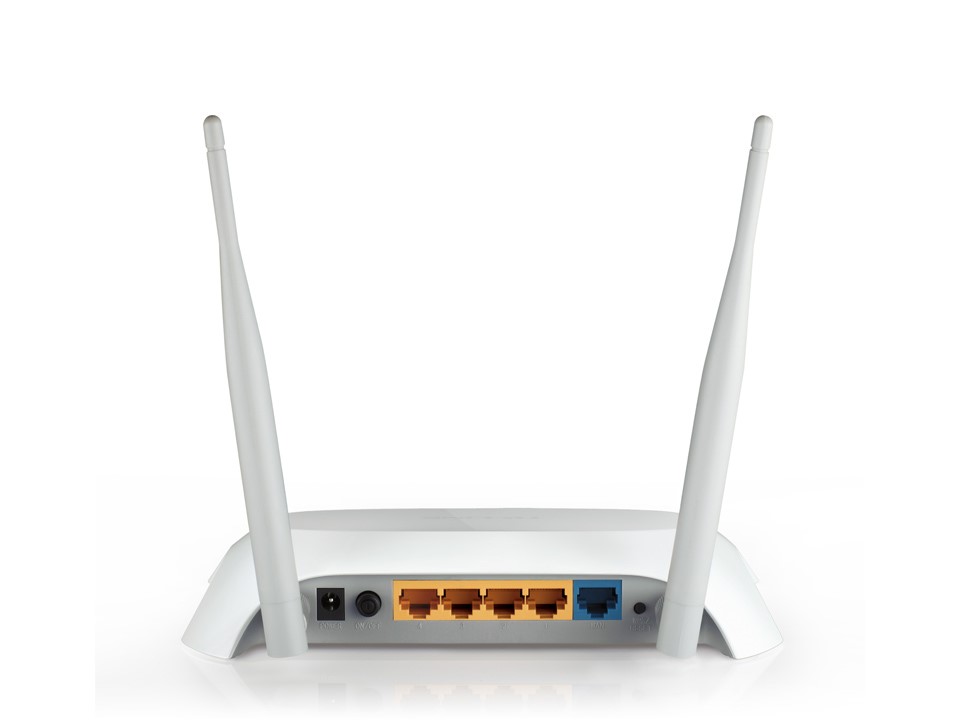
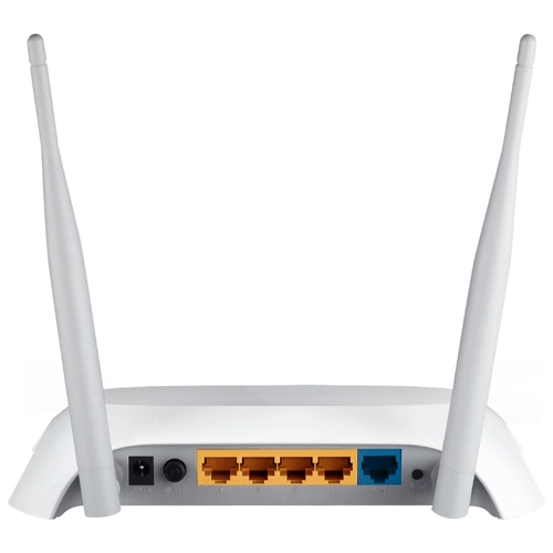
В остальном все шаблонно: 1 WAN, 4 LAN, кнопка QSS, кнопка включения/выключения, утопленная в корпус кнопка Wi-Fi. На передней панели размещена индикация.
Настройки
В целом, настройки роутера TP-Link TL-MR3420 можно делать в любой последовательности. Главное, чтобы был доступ к веб-интерфейсу маршрутизатора. Если роутером пользовались, перед началом, рекомендуется сбросить настройки до заводских. Сделать это можно, зажав на 10 секунд кнопку QSS/Reset на задней части корпуса.
Данная модель работает с обновленным интерфейсом и с автоматически включенным DHCP-сервером (назначаются IP-адреса компьютерам, смартфонам и прочим сетевым устройствам автоматически), что делает настройку еще легче.
Самое полное руководство по работе и настройке роутера TP-Link TL–MR3420 на русском языке можно скачать ЗДЕСЬ.
Физическое подключение интернета
Если используете интернет от провайдера, подключайте кабель, который идет в квартиру, в разъем WAN. Можно вместо или вместе с проводным интернетом подключить 3G/4G модем по USB, чтобы получать интернет из двух источников.
Включение Wi-Fi или соединение ПК с роутером по LAN
На корпусе, со стороны USB порта, нажмите на кнопку Wi-Fi. Если индикация беспроводной сети загорелась, можете подключаться к роутеру через Wi-Fi точку:
- Откройте раздел поиска сетей Wi-Fi.
- Присоединитесь к точке, с названием модели вашего роутера.
- Готово, можно входить через браузер в веб-интерфейс настроек.
Чтобы подключить устройства проводным способом, соедините сетевой порт компьютера и LAN роутера Ethernet-кабелем.
Вход в веб-интерфейс
Для входа в веб-интерфейс личного кабинета, перейдите по адресу tplinkwifi.net или 192.168.0.1. Создайте и подтвердите пароль для будущих входов.
Затем жмите кнопку входа.
Быстрая настройка
В веб-интерфейсе есть функция быстрой настройки TP-Link TL–MR3420 на тот режим, который нужен. Вот вам инструкция:
- Зайдите в раздел «Quick Setup» и выберите «Time zone».
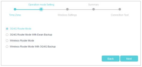
- В мастере установки выбирайте нужный вам режим и жмите Next.
- Если используете только WAN подключение, выберите Wireless Mode.
- Если интернет получаете от WAN и 4G-модема, и хотите, чтобы они работали в режиме «always ON», то есть автоматически переключалась работа интернета на другой канал, при отсутствии такового на первом, выберите Wireless Router Mode with 3G/4G Backup.
- А если интернет только от USB-модема, ваш выбор – 3G/4G Router Mode.
- В следующем пункте выставите настройки Wi-Fi точки: измените имя, тип безопасности, придумайте пароль.
- Просмотрите ваши изменения и проверьте доступность соединения.
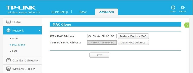
NB! Если зарегистрированный MAC-адрес устройства, который провайдер прописал для регистрации, отличается от фактического, интернет может не предоставляться.
Для корректной работы перейдите в Advanced – Network – Mac Clone, пропишите нужный мак-адрес в разделе WAN (что выдал провайдер) и жмите Save.
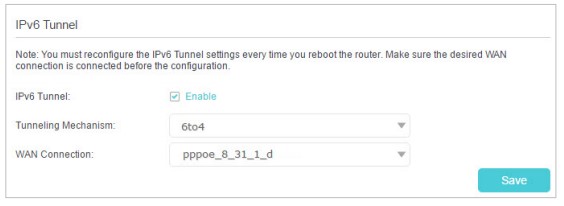
Дополнительно, чтобы без проблем открывались сайты, работающие на IPv6, рекомендуется использовать следующую инструкцию:
- Зайдите в Advanced – Network – IPv6 Tunnel.
- Выберите туннелирование 6to4.
- В выпадающем списке выберите WAN connection.
- Жмите «Save».
О том, как обновить и настроить маршрутизатор, рассказано и показано в следующем видео (русский интерфейс):
Изменение настроек входа
Пароль для входа вы задали изначально, но можно зарегистрироваться в TP-Link ID для входа в веб-интерфейс или приложение для мобильного, и управлять роутером удаленно.
Чтобы сделать такую настройку роутера TP-Link TL-MR3420, нужно:
- Зайти в раздел TP-Link Cloud.
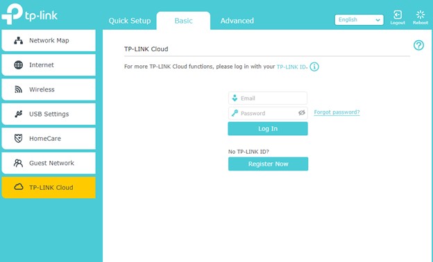
- Нажать Register Now.
- Указать почтовый ящик, от которого у вас есть доступ.
- Получить на него письмо с активацией.
- Придумать пароль и сохранить его.
- Почта и пароль в дальнейшем понадобятся для входа в веб-панель.
Если вам нужно управлять роутером удаленно, обязательно установить на смартфон приложение TP-Link Tether.
Заключение
С помощью легкого подключения и быстрой настройки, можно организовать правильную работу сети и стабильный выход в интернет за 10 минут. Веб-интерфейс маршрутизатора в целом понятен, поэтому персонализация параметров устройства не вызовет затруднений, даже если включен не русский интерфейс.
TL-MR3420
3G/4G Wireless N Router
Rev: 2.0.0
1910010676

COPYRIGHT & TRADEMARKS
Specifications are subject to change without notice. is a registered trademark of
TP-LINK TECHNOLOGIES CO., LTD. Other brands and product names are trademarks or
registered trademarks of their respective holders.
No part of the specifications may be reproduced in any form or by any means or used to make any
derivative such as translation, transformation, or adaptation without permission from TP-LINK
TECHNOLOGIES CO., LTD. Copyright © 2012 TP-LINK TECHNOLOGIES CO., LTD. All rights
reserved.
http://www.tp-link.com

FCC STATEMENT
This equipment has been tested and found to comply with the limits for a Class B digital device,
pursuant to part 15 of the FCC Rules. These limits are designed to provide reasonable protection
against harmful interference in a residential installation. This equipment generates, uses and can
radiate radio frequency energy and, if not installed and used in accordance with the instructions,
may cause harmful interference to radio communications. However, there is no guarantee that
interference will not occur in a particular installation. If this equipment does cause harmful
interference to radio or television reception, which can be determined by turning the equipment off
and on, the user is encouraged to try to correct the interference by one or more of the following
measures:
Reorient or relocate the receiving antenna.
Increase the separation between the equipment and receiver.
Connect the equipment into an outlet on a circuit different from that to which the receiver
is connected.
Consult the dealer or an experienced radio/ TV technician for help.
This device complies with part 15 of the FCC Rules. Operation is subject to the following two
conditions:
This device may not cause harmful interference.
This device must accept any interference received, including interference that may cause
undesired operation.
Any changes or modifications not expressly approved by the party responsible for compliance
could void the user’s authority to operate the equipment.
Note: The manufacturer is not responsible for any radio or TV interference caused by
unauthorized modifications to this equipment. Such modifications could void the user’s authority
to operate the equipment.
FCC RF Radiation Exposure Statement:
This equipment complies with FCC RF radiation exposure limits set forth for an uncontrolled
environment. This device and its antenna must not be co-located or operating in conjunction with
any other antenna or transmitter.
“To comply with FCC RF exposure compliance requirements, this grant is applicable to only
Mobile Configurations. The antennas used for this transmitter must be installed to provide a
separation distance of at least 20 cm from all persons and must not be co-located or operating in
conjunction with any other antenna or transmitter.”

CE Mark Warning
This is a class B product. In a domestic environment, this product may cause radio interference, in
which case the user may be required to take adequate measures.
National Restrictions
This device is intended for home and office use in all EU countries (and other countries following
the EU directive 1999/5/EC) without any limitation except for the countries mentioned below:
Country Restriction Reason/remark
Bulgaria None
Outdoor use limited to
10 mW e.i.r.p. within
France
the band 2454-2483.5
MHz
Italy None
Luxembourg None
Norway Implemented
Russian Federation None Only for indoor applications
Note: Please don’t use the product outdoors in France.
General authorization required for outdoor use and
public service
Military Radiolocation use. Refarming of the 2.4 GHz
band has been ongoing in recent years to allow current
relaxed regulation. Full implementation planned 2012
If used outside of own premises, general authorization is
required
General authorization required for network and service
supply(not for spectrum)
This subsection does not apply for the geographical area
within a radius of 20 km from the centre of Ny-Ålesund
This device has been designed to operate with the antennas listed below, and having a maximum
gain of 5 dBi. Antennas not included in this list or having a gain greater than 5 dBi are strictly
prohibited for use with this device. The required antenna impedance is 50 ohms.
To reduce potential radio interference to other users, the antenna type and its gain should be so
chosen that the equivalent isotropically radiated power (e.i.r.p.) is not more than that permitted for
successful communication.”
Industry Canada Statement:
This device complies with RSS-210 of the Industry Canada Rules. Operation is subject to the
following two conditions:
(1)This device may not cause harmful interference, and
(2)This device must accept any interference received, including interference that may cause
undesired operation.

IMPORTANT NOTE:
Radiation Exposure Statement:
This equipment complies with Canada radiation exposure limits set forth for an uncontrolled
environment. This equipment should be installed and operated with minimum distance 20cm
between the radiator & your body.
Ce dispositif est conforme à la norme CNR-210 d’Industrie Canada applicable aux appareils radio
exempts de licence. Son fonctionnement est sujet aux deux conditions suivantes:
(1)Le dispositif ne doit pas produire de brouillage préjudiciable, et
(2)Ce dispositif doit accepter tout brouillage reçu,y compris un brouillage susceptible de
provoquer un fonctionnement indésirable.
NOTE IMPORTANTE:
Déclaration d’exposition aux radiations:
Cet équipement est conforme aux limites d’exposition aux rayonnements IC établies pour un
environnement non contrôlé. Cet équipement doit être installé et utilisé avec un minimum de 20
cm de distance entre la source de rayonnement et votre corps.
Korea Warning Statements:
당해 무선설비는 운용중 전파혼신 가능성이 있음.
NCC Notice:
經型式認證合格之低功率射頻電機,非經許可,公司、商號或使用者均不得擅自變更頻率、加大功
率或變更原設計之特性及功能。
低功率射頻電機之使用不得影響飛航安全及干擾合法通信;經發現有干擾現象時,應立即停用,並
改善至無干擾時方得繼續使用。前項合法通信,指依電信法規定作業之無線電通信。低功率射頻電
機須忍受合法通信或工業、科學及醫療用電波輻射性電機設備之干擾。
Продукт сертифіковано згідно с правилами системи УкрСЕПРО на відповідність вимогам
нормативних документів та вимогам, що передбачені чинними законодавчими актами
України.

TP-LINK TECHNOLOGIES CO., LTD
DECLARATION OF CONFORMITY
For the following equipment:
Product Description: 3G/4G Wireless N Router
Model No.: TL-MR3420
Trademark: TP-LINK
We declare under our own responsibility that the above products satisfy all the technical
regulations applicable to the product within the scope of Council Directives:
Directives 1999/5/EC, Directives 2004/108/EC, Directives 2006/95/EC, Directives 1999/519/EC,
Directives 2011/65/EU
The above product is in conformity with the following standards or other normative documents
ETSI EN 300 328 V1.7.1: 2006
ETSI EN 301 489-1 V1.8.1:2008& ETSI EN 301 489-17 V2.1.1:2009
EN 55022:2010
EN 55024:2010
EN 61000-3-2:2006+A1:2009+A2:2009
EN 61000-3-3:2008
EN60950-1:2006+A11:2009+A1:2010+A12:2011
EN62311:2008
The product carries the CE Mark:
Person is responsible for marking this declaration:
Yang Hongliang
Product Manager of International Business
Date of issue: 2012
TP-LINK TECHNOLOGIES CO., LTD.
Building 24 (floors 1, 3, 4, 5), and 28 (floors 1-4) Central Science and Technology Park,
Shennan Rd, Nanshan, Shenzhen, China

CONTENTS
Package Contents…………………………………………………………………………………………. 1
Chapter 1. Introduction…………………………………………………………………………….. 2
1.1 Overview of the Router……………………………………………………………………………………. 2
1.2 Conventions ………………………………………………………………………………………………….. 2
1.3 Main Features ……………………………………………………………………………………………….. 2
1.4 Panel Layout …………………………………………………………………………………………………. 3
1.4.1 The Front Panel…………………………………………………………………………………… 3
1.4.2 The Rear Panel …………………………………………………………………………………… 4
1.4.3 The Side Panel……………………………………………………………………………………. 4
Chapter 2. Connecting the Router …………………………………………………………….. 5
2.1 System Requirements …………………………………………………………………………………….. 5
2.2 Installation Environment Requirements……………………………………………………………… 5
2.3 Connecting the Router ……………………………………………………………………………………. 5
Chapter 3. Quick Installation Guide…………………………………………………………… 7
3.1 TCP/IP Configuration ……………………………………………………………………………………… 7
3.2 Quick Installation Guide ………………………………………………………………………………….. 7
Chapter 4. Configuring the Router…………………………………………………………… 13
4.1 Login ………………………………………………………………………………………………………….. 13
4.2 Status …………………………………………………………………………………………………………. 13
4.3 Quick Setup…………………………………………………………………………………………………. 14
4.4 WPS…………………………………………………………………………………………………………… 14
4.5 Network ………………………………………………………………………………………………………. 21
4.5.1 Internet Access………………………………………………………………………………….. 21
4.5.2 3G/4G………………………………………………………………………………………………. 22
4.5.3 WAN ………………………………………………………………………………………………… 26
4.5.4 MAC Clone ……………………………………………………………………………………….. 35
4.5.5 LAN………………………………………………………………………………………………….. 35
4.6 Wireless ……………………………………………………………………………………………………… 36
4.6.1 Wireless Settings……………………………………………………………………………….. 36
4.6.2 Wireless Security……………………………………………………………………………….. 38
4.6.3 Wireless MAC Filtering ……………………………………………………………………….. 41
4.6.4 Wireless Advanced …………………………………………………………………………….. 43
4.6.5 Wireless Statistics………………………………………………………………………………. 45
4.7 DHCP …………………………………………………………………………………………………………. 45
I

4.7.1 DHCP Settings ………………………………………………………………………………….. 46
4.7.2 DHCP Client List………………………………………………………………………………… 47
4.7.3 Address Reservation ………………………………………………………………………….. 47
4.8 Forwarding ………………………………………………………………………………………………….. 48
4.8.1 Virtual Servers…………………………………………………………………………………… 48
4.8.2 Port Triggering…………………………………………………………………………………… 50
4.8.3 DMZ…………………………………………………………………………………………………. 52
4.8.4 UPnP ……………………………………………………………………………………………….. 53
4.9 Security ………………………………………………………………………………………………………. 54
4.9.1 Basic Security……………………………………………………………………………………. 54
4.9.2 Advanced Security……………………………………………………………………………… 55
4.9.3 Local Management …………………………………………………………………………….. 57
4.9.4 Remote Management …………………………………………………………………………. 58
4.10 Parental Control …………………………………………………………………………………………… 58
4.11 Access Control …………………………………………………………………………………………….. 61
4.11.1 Rule …………………………………………………………………………………………………. 62
4.11.2 Host …………………………………………………………………………………………………. 64
4.11.3 Target……………………………………………………………………………………………….. 65
4.11.4 Schedule…………………………………………………………………………………………… 67
4.12 Advanced Routing ………………………………………………………………………………………… 68
4.12.1 Static Routing List………………………………………………………………………………. 69
4.12.2 System Routing Table…………………………………………………………………………. 70
4.13 Bandwidth Control ………………………………………………………………………………………… 70
4.13.1 Control Settings …………………………………………………………………………………. 70
4.13.2 Rule List……………………………………………………………………………………………. 71
4.14 IP & MAC Binding…………………………………………………………………………………………. 72
4.14.1 Binding Settings…………………………………………………………………………………. 72
4.14.2 ARP List……………………………………………………………………………………………. 74
4.15 Dynamic DNS………………………………………………………………………………………………. 74
4.15.1 Comexe.cn DDNS ……………………………………………………………………………… 74
4.15.2 Dyndns.org DDNS ……………………………………………………………………………… 75
4.15.3 No-ip.com DDNS ……………………………………………………………………………….. 76
4.16 System Tools ……………………………………………………………………………………………….. 77
4.16.1 Time Settings…………………………………………………………………………………….. 77
4.16.2 Diagnostic…………………………………………………………………………………………. 78
4.16.3 Firmware Upgrade……………………………………………………………………………… 80
4.16.4 Factory Defaults ………………………………………………………………………………… 81
II III

4.16.5 Backup & Restore………………………………………………………………………………. 81
4.16.6 Reboot……………………………………………………………………………………………… 82
4.16.7 Password………………………………………………………………………………………….. 82
4.16.8 System Log……………………………………………………………………………………….. 83
4.16.9 Statistics …………………………………………………………………………………………… 85
Appendix A: FAQ…………………………………………………………………………………………. 87
Appendix B: Configuring the PCs ………………………………………………………………… 92
Appendix C: Specifications………………………………………………………………………….. 96
Appendix D: Glossary …………………………………………………………………………………. 97
Appendix E: Compatible 3G/4G USB Modem ………………………………………………… 99

TL-MR3420 3G/4G Wireless N Router User Guide
Package Contents
The following items should be found in your package:
TL-MR3420 3G/4G Wireless N Router
DC Power Adapter for TL-MR3420 3G/4G Wireless N Router
Ethernet Cable
Quick Installation Guide
Resource CD for TL-MR3420 3G/4G Wireless N Router, including:
This Guide
Other Helpful Information
Note:
Make sure that the package contains the above items. If any of the listed items is damaged or
missing, please contact with your distributor.
-1-

TL-MR3420 3G/4G Wireless N Router User Guide
Chapter 1. Introduction
1.1 Overview of the Router
TP-LINK understands the need for sharing the 3G/4G connection locally that benefits our end
users. We realize the convenience with our latest wireless N 3G/4G Routers —— they give you
the freedom to quickly set up a stable and high speed wireless network, up to 300Mbps,
on-the-go and share a 3G/4G connection. By connecting a USB Card to the Router, a Wi-Fi
hotspot is instantly established allowing users to share a Internet connection anywhere 3G/4G
coverage is available. So whether you’re on the train, camping, or at a construction site, you’ll
have a reliable wireless connection to accommodate your networking needs.
3G/4G and WAN Broadband
The TL-MR3
dynamic IP) two kinds of broadband connections to get on the Internet, you can via the Internet
no matter at home or outside on business. Automatic 3G/4G and WAN failover feature just
provide nonstop internet connection.
TP-LINK 3G/4G Router provides up to 300Mbps, faster than that of traditional 11g products,
surpasses 11G performance enabling the use of high bandwidth-consuming applications such
as HD Videos.
With just pre
connection for solid security in under a minute.
420 3G/4G Wireless N Router provides 3G/4G and WAN (xDSL, static IP, or
Incredibly High Speed
Wi-fi Protected Setup
ssing on the ‘WPS’ button, the Router automatically establishes a WPA2 secure
1.2 Conventions
The Router or TL-MR3420 mentioned in this guide stands for TL-MR3420 3G/4G Wireless N
Router without any explanation.
1.3 Main Features
One 10/100M Auto-Negotiation RJ45 WAN port, four 10/100M Auto-Negotiation RJ45 LAN
ports, supporting Auto MDI/MDIX
Compatible with LTE/HSPA+/HSUPA/HSDPA/UMTS/EVDO USB modem
Automatic 3G/4G and WAN failover
Wireless N speed up to 300Mbps
2T2R MIMO, CCA technologies deliver greater coverage and higher speed
Wireless security encryption easily at a push of “WPS” button
WDS wireless bridge provides seamless bridging to expand your wireless network
-2-
TL-MR3420 3G/4G Wireless N Router User Guide
Backward compatible with 802.11b and 802.11g devices
Provides WPA/WPA2-Enterprise, WPA/WPA2-Personal authentication, TKIP/AES
encryption security
Supports 3G/4G/Dynamic IP/Static IP/PPPoE/L2TP/PPTP Internet access
Supports Virtual Server, Special Application and DMZ host
Supports UPnP, Dynamic DNS, Static Routing
Provides Automatic-connection and Scheduled Connection on certain time to the Internet
Built-in NAT and DHCP server supporting static IP address distributing
Connects Internet on demand and disconnects from the Internet when idle for PPPoE
Provides 64/128-bit WEP encryption security and wireless LAN ACL (Access Control List)
Supports Flow Statistics
Supports firmware upgrade and Web management
1.4 Panel Layout
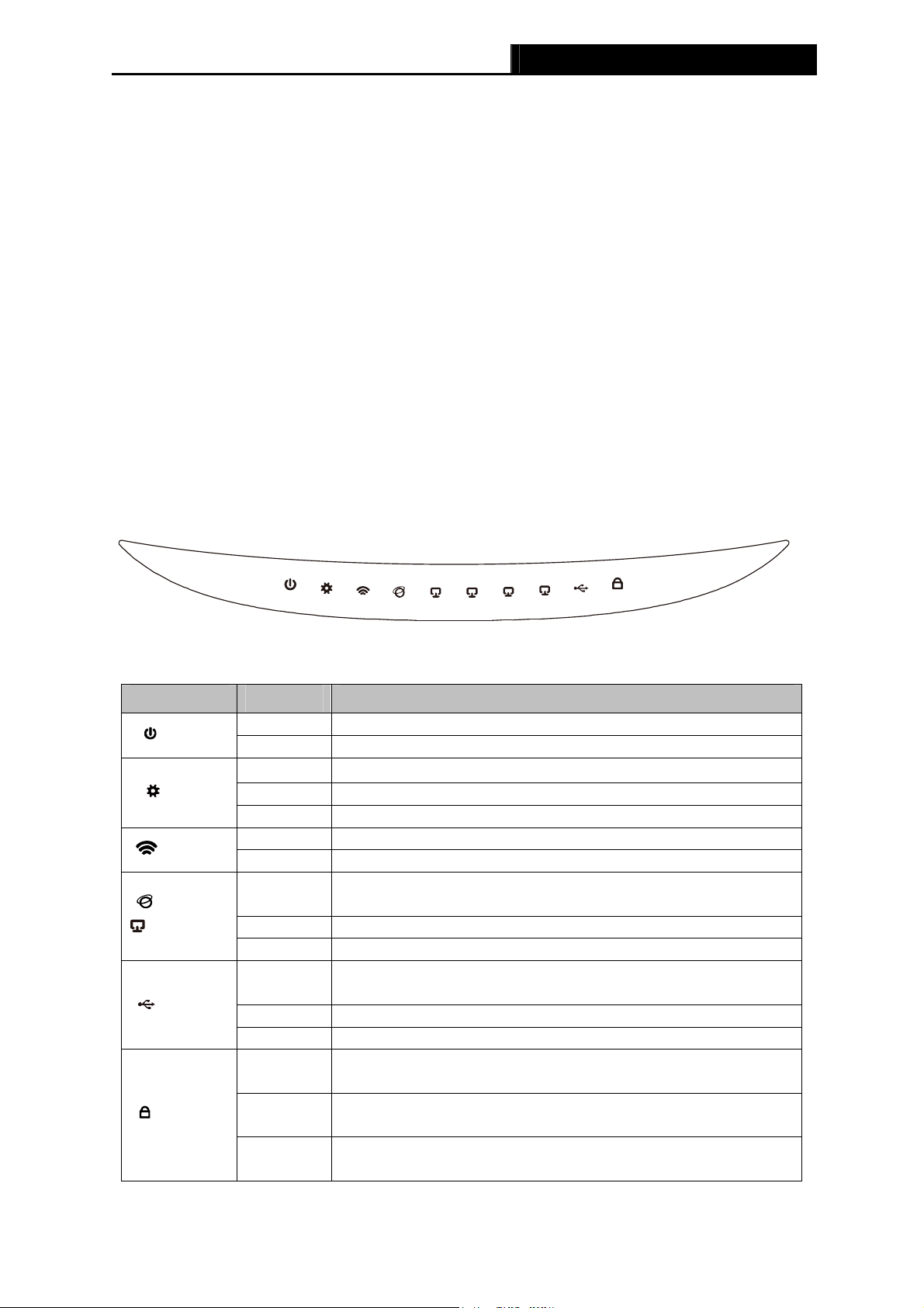
1.4.1 The Front Panel
Figure 1-1 Front Panel sketch
The Router’s LEDs are located on the front panel (View from left to right).
Item Status Indication
(PWR)
(SYS)
(WLAN)
(WAN)
(LAN1-4)
(USB)
(WPS)
On Power is on.
Off Power is off.
On
The Router is initializing.
Flashing The Router is working properly.
Off The Router has a system error.
Flashing The Wireless function is enabled.
Off The Wireless function is disabled.
On
A device is linked to the corresponding port but there is no
activity.
Flashing An active device is linked to the corresponding port.
Off No device is linked to the corresponding port.
On
The USB 3G/4G modem is connected but no data being
transferred.
Flashing Data is received or sent through the 3G/4G modem.
Off The USB 3G/4G modem is not connected.
Slow
Flash
On
Quick
Flash
A wireless device is connecting to the network by WPS
function. This process will last in the first 2 minutes.
A wireless device has been successfully added to the network
by WPS function.
A wireless device failed to be added to the network by WPS
function.
Table 1-1 The LEDs description
-3-
TL-MR3420 3G/4G Wireless N Router User Guide
Note:
After a device is successfully added to the network by WPS function, the WPS LED will keep on
for about 5 minutes and then turn off.
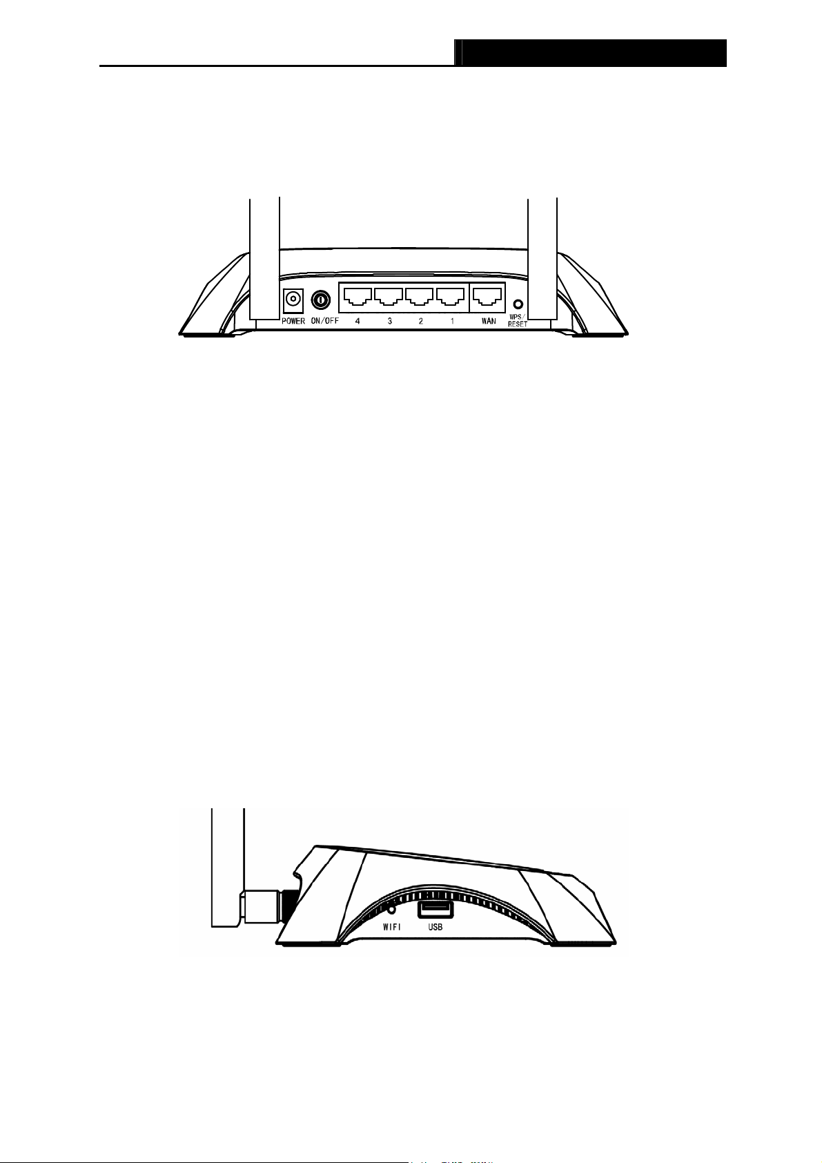
1.4.2 The Rear Panel
Figure 1-2 Rear Panel sketch
The following parts are located on the rear panel (View from left to right).
POWER: The Power socket is where you will connect the power adapter. Please use the
power adapter provided with this TL-MR3420 3G/4G Wireless N Router.
ON/OFF: The switch is for you to turn on/off the Router, but only with the Router powered
on.
4,3,2,1 (LAN): These ports (4,3,2,1) connect the Router to the local PC(s)
WAN: This WAN port is where you will connect the DSL/cable Modem, or Ethernet
WPS/RESET:
There are two ways to reset to the Router’s factory defaults:
1) Use the Factory Defaults function on “System Tools -> Factory Defaults” page in
the Router’s Web-based Utility.
2) Use the Factory Default Reset button: With the Router powered on, use a pin to press
and hold the WPS/RESET button (about 5 seconds) until the SYS LED becomes
quick-flash from slow-flash. And then release the button and wait the Router to reboot
to its factory default settings.
Wireless antenna: To receive and transmit the wireless data.
1.4.3 The Side Panel
Figure 1-3 Side Panel sketch
The following parts are located on the side plate (View from left to right).
WIFI: This switch is an easy and convenient operation for you to turn on or off the wireless
network.
USB: Connect to the USB Modem.
-4-

TL-MR3420 3G/4G Wireless N Router User Guide
Chapter 2. Connecting the Router
2.1 System Requirements
Broadband Internet Access Service (DSL/Cable/Ethernet)
One DSL/Cable Modem that has an RJ45 connector (which is not necessary if the Router
is connected directly to the Ethernet.)
PCs with a working Ethernet Adapter and an Ethernet cable with RJ45 connectors
TCP/IP protocol on each PC
Web browser, such as Microsoft Internet Explorer 5.0 , Netscape Navigator 6.0 or above
2.2 Installation Environment Requirements
Place the Router in a well ventilated place far from any heater or heating vent
Avoid direct irradiation of any strong light (such as sunlight)
Keep at least 2 inches (5 cm) of clear space around the Router
Operating Temperature: 0 ~40 (32 ~104 )
Operating Humidity: 10%~90%RH, Non-condensing
2.3 Connecting the Router
Before installing the Router, make sure your PC is connected to the Internet through the
broadband service successfully. If there is any problem, please contact your ISP. After that,
please install the Router according to the following steps. Don’t forget to pull out the power plug
and keep your hands dry.
1. Power off your Cable/DSL Modem, and the Router.
2. Locate an optimum location for the Router. The best place is usually at the center of your
wireless network. The place must accord with the Installation Environment Requirements
3. Adjust the direction of the antenna. Normally, upright is a good direction.
4. Connect the PC(s) or Switch/Hub in your LAN to the LAN Ports of the 3G/4G Router with
Ethernet cable.
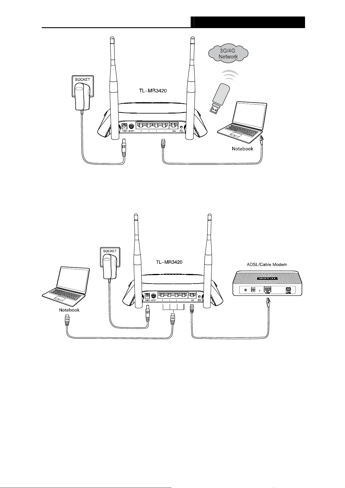
5. The 3G/4G Router supports both 3G/4G and WAN connection; so you can insert 3G/4G
USB Modem to the USB port of the Router (as shown in Figure 2-1), or connect the
.
DSL/Cable Modem to the WAN port of the Router (as shown in Figure 2-2). Please visit our
website http://www.tp-link.com to get the latest USB modems compatibility, and we
recommend
you to check whether the modem in your hand has already been tested by us.
6. Connect the power adapter to the power socket on the Router, and the other end into an
electrical outlet. The Router will start to work automatically.
7. Power on your Cable/DSL Modem.
-5-
TL-MR3420 3G/4G Wireless N Router User Guide
Figure 2-1 Hardware Installation – 3G/4G connection
Figure 2-2 Hardware Installation – WAN connection
-6-

TL-MR3420 3G/4G Wireless N Router User Guide
Chapter 3. Quick Installation Guide
This chapter will show you how to configure the basic functions of your 3G/4G Wireless N
Router using Quick Setup Wizard within minutes.
3.1 TCP/IP Configuration
The default IP address of the 3G/4G Wireless N Router is 192.168.0.1. And the default Subnet
Mask is 255.255.255.0. These values can be changed as you desire. In this guide, we use all
the default values for description.
Connect the local PC to the LAN ports of the Router. And then you can configure the IP address
for your PC in the following two ways.
Configure the IP address manually
1) Set up the TCP/IP Protocol for your PC. If you need instructions as to how to do this,
please refer to Appendix B: «Configuring the PC.»
2) Configure the network parameters. The IP address is 192.168.0.xxx («xxx» is any number
from 2 to 254), Subnet Mask is 255.255.255.0, and Gateway is 192.168.0.1 (The Router’s
default IP address)
Obtain an IP address automatically
1) Set up the TCP/IP Protocol in «Obtain an IP address automatically» mode on your PC. If
you need instructions as to how to do this, please refer to Appendix B: «Configuring the
PC.»
2) Then the built-in DHCP server will assign IP address for the PC.
3.2 Quick Installation Guide
Note:
If you are trying to connect to TL-MR3420 wirelessly, please refer to the label on the bottom of
the Router for the Wireless Password.
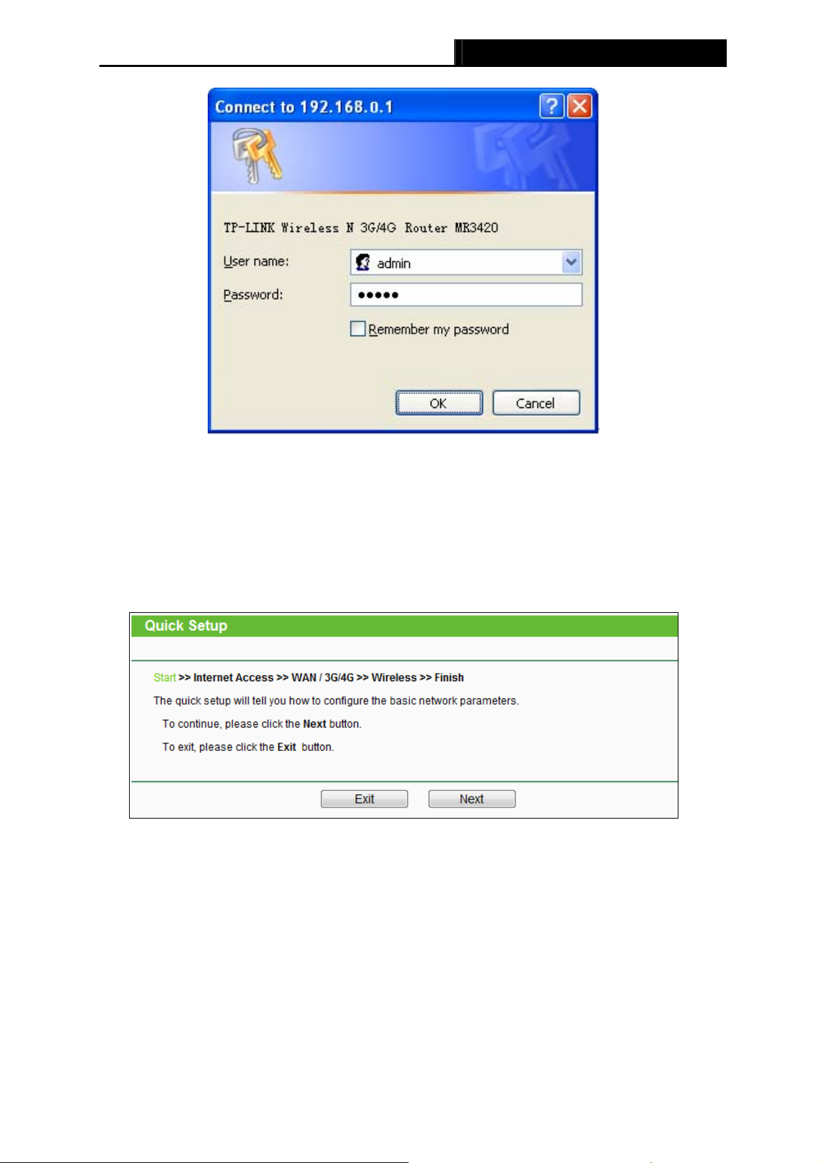
1. To access the configuration utility, open a web-browser and type in the default address
http://192.168.0.1
in the address field of the browser.
Figure 3-1 Login the Router
After a moment, a login window will appear, similar to the Figure 3-2. Enter admin for the User
Name and Password, both in lower case letters. Then click the OK button or press the Enter
key.
-7-
TL-MR3420 3G/4G Wireless N Router User Guide
Figure 3-2 Login Windows
Note:
If the above screen does not pop-up, it means that your Web-browser has been set to a proxy.
Go to Tools menu>Internet Options>Connections>LAN Settings, in the screen that appears,
cancel the Using Proxy checkbox, and click OK to finish it.
2. After successful login, you can click the Quick Setup to quickly configure your Router.
Click Next to proceed to the next screen.
Figure 3-3 Quick Setup
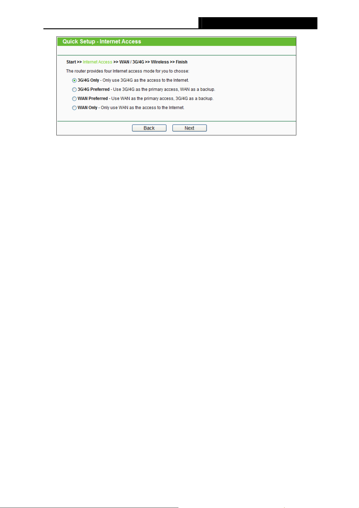
3. Select a desired Internet Access mode and then click Next. The configuration for each
mode is similar. As follows we will take 3G/4G Only mode for example.
-8-
TL-MR3420 3G/4G Wireless N Router User Guide
Figure 3-4 Choose Internet Access Mode
3G/4G Only
In this mode, the Router will try 3G/4G access only. WAN access is disabled.
3G/4G Preferred
In this mode, the Router will try 3G/4G access first. If 3G/4G access fails and WAN
access is valid, or if no 3G/4G USB modem is inserted, the Router would switch to WAN
access. Once the Router succeeds to connect to the 3G/4G network, the Router would
stop the WAN connection and switch back to 3G/4G access immediately.
WAN Preferred
In this mode, the Router will try WAN access first. If the WAN access fails and 3G/4G
access is valid, the Router would switch to 3G/4G access. Once the Router succeeds to
connect to the WAN network, the Router would stop the 3G/4G connection and switch
back to WAN access immediately.
WAN Only
In this mode, the Router will try WAN access only. 3G/4G access is disabled.
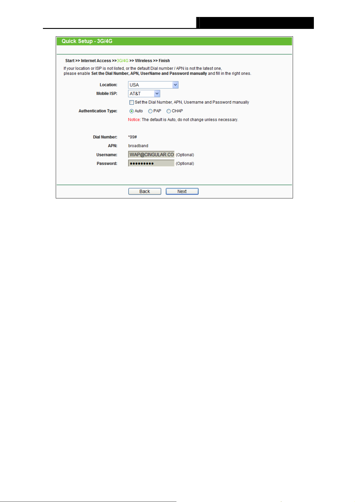
4. The next screen will appear as shown in Figure 3-5. You need to set the required
parameters and then click Next.
-9-
TL-MR3420 3G/4G Wireless N Router User Guide
Figure 3-5
Location — Select the location where you’re enjoying the 3G/4G card.
Mobile ISP — Select the ISP (Internet Service Provider) you apply to for 3G/4G service. The
Router will show the default Dial Number and APN of that ISP. If your ISP is not listed in the
Mobile ISP, check the box before Set the Dial Number, APN, Username and Password
manually and fill the Dial Number and APN blanks below.
Authentication Type — Some ISPs need a specific authentication type. Please confirm it
with your ISP or keep it Auto.
Dial Number & APN — Set these two parameters manually after Set the Dial Number, APN,
Username and Password manually is checked.
Username/Password — Enter the Username and Password provided by your ISP. These
fields are optional but case-sensitive.
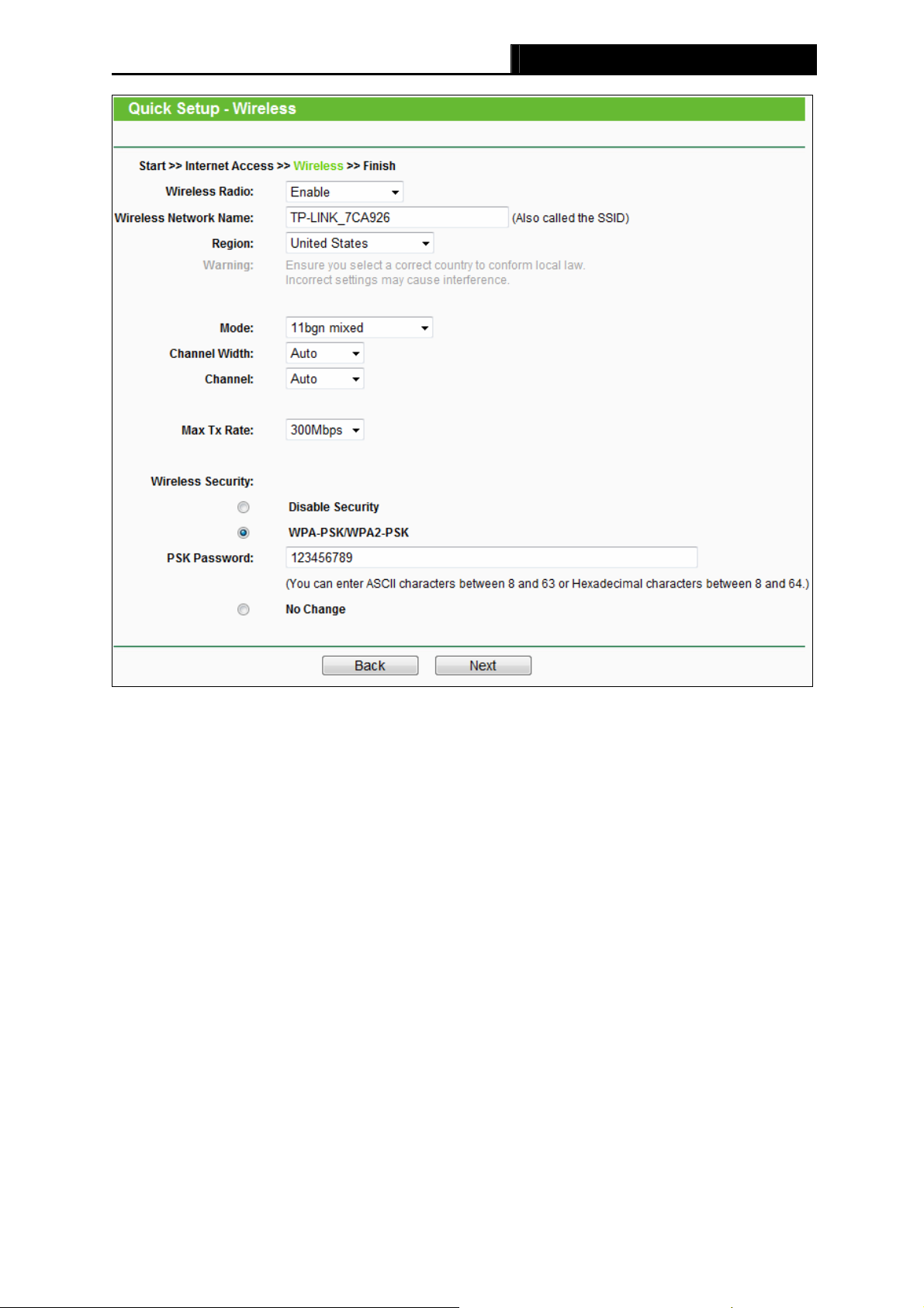
5. Configure the Wireless settings on the screen as shown in Figure 3-6, then click Next.
-10-
TL-MR3420 3G/4G Wireless N Router User Guide
Figure 3-6 Quick Setup – Wireless
Wireless Radio — Enable or disable the wireless radio choosing from the pull-down list.
Wireless Network Name — Enter a value of up to 32 characters. The same name of
Wireless Network Name (SSID) must be assigned to all wireless devices in your network.
Considering your wireless network security, the default Wireless Network Name is set to
be TP-LINK_XXXXXX (XXXXXX indicates the last six unique numbers of each Router’s
MAC address). This value is case-sensitive. For example, TEST is NOT the same as test.
Region — Select your region from the pull-down list. This field specifies the region where
the wireless function of the Router can be used. It may be illegal to use the wireless
function of the Router in a region other than one of those specified in this field. If your
country or region is not listed, please contact your local government agency for
assistance.
Mode — This field determines the wireless mode which the Router works on.
Channel Width — Select any channel width from the pull-down list. The default setting is
automatic, which can adjust the channel width for your clients automatically.
Channel — This field determines which operating frequency will be used. The default
channel is set to Auto, so the AP will choose the best channel automatically. It is not
necessary to change the wireless channel unless you notice interference problems with
another nearby access point.
-11-
TL-MR3420 3G/4G Wireless N Router User Guide
Wireless Security — You can select one of the following security options.
Disable Security — The wireless security function can be enabled or disabled. If
disabled, the wireless stations will be able to connect the Router without encryption. It
is recommended strongly that you choose one of following options to enable security.
WPA-PSK/WPA2-PSK — Select WPA based on pre-shared passphrase.
PSK Password — You can enter ASCII or Hexadecimal characters.
For ASCII, the key can be made up of any numbers 0 to 9 and any letters A to Z, the
length should be between 8 and 63 characters.
For Hexadecimal, the key can be made up of any numbers 0 to 9 and letters A to F,
the length should be between 8 and 64 characters.
Please also note the key is case sensitive, this means that upper and lower case keys
will affect the outcome. It would also be a good idea to write down the key and all
related wireless security settings.
No change — If you choose this option, wireless security configuration will not change!
These settings are only for basic wireless parameters. For advanced settings, please refer to
Section 4.6: “Wireless”.
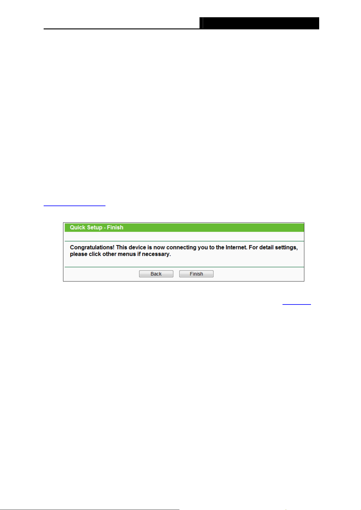
6. Click Finish to complete the Quick Setup.
Figure 3-7 Quick Setup – Finish
After the rebooting, please check whether you can access the Internet or not in the 4.2 Status
page.
-12-
TL-MR3420 3G/4G Wireless N Router User Guide
Chapter 4. Configuring the Router
This chapter will show each Web page’s key functions and the configuration way.
4.1 Login
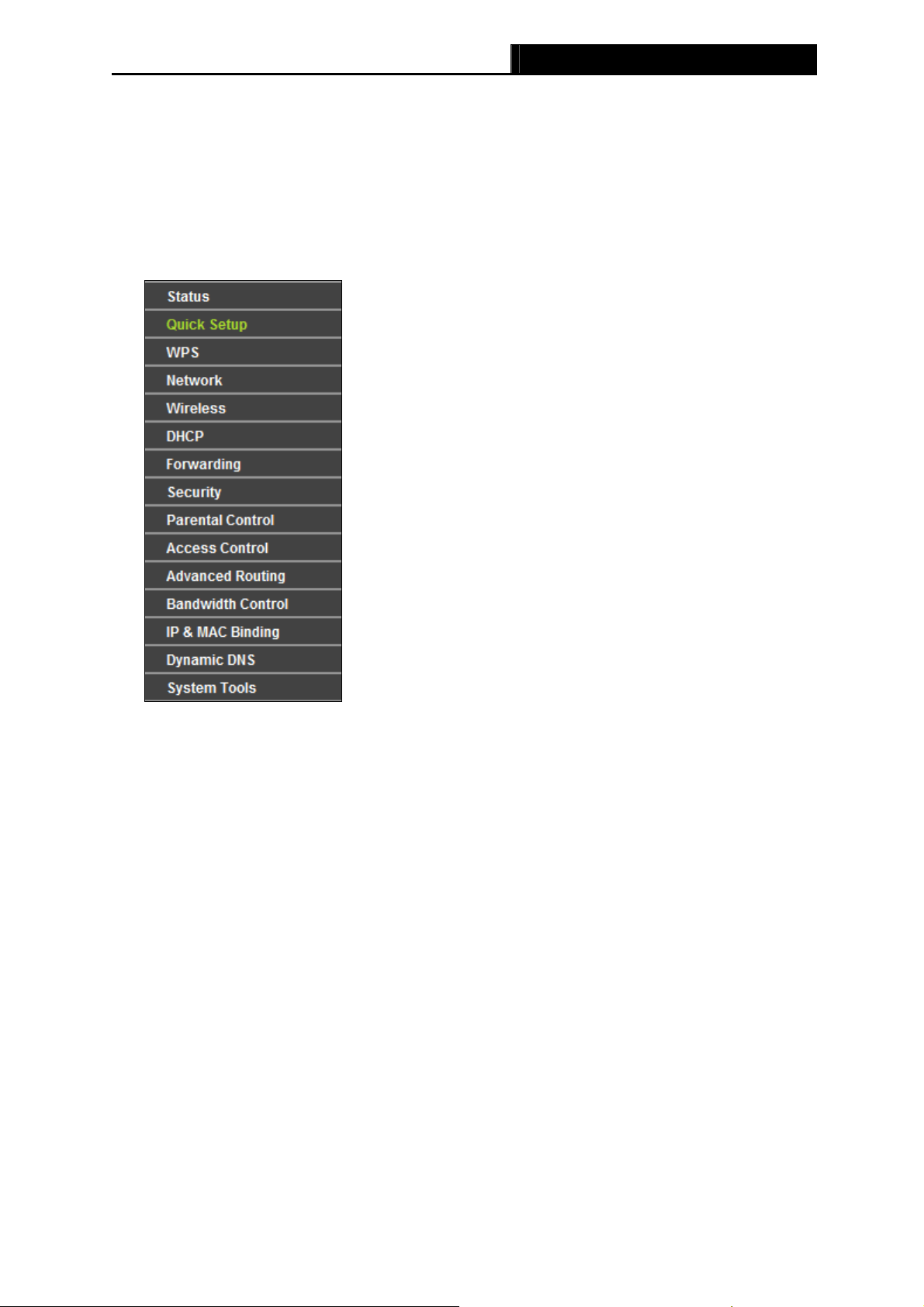
After your successful login, you will see the fifteen main menus on the left of the Web-based utility.
On the right, there are the corresponding explanations and instructions.
The detailed explanations for each Web page’s key function are listed below.
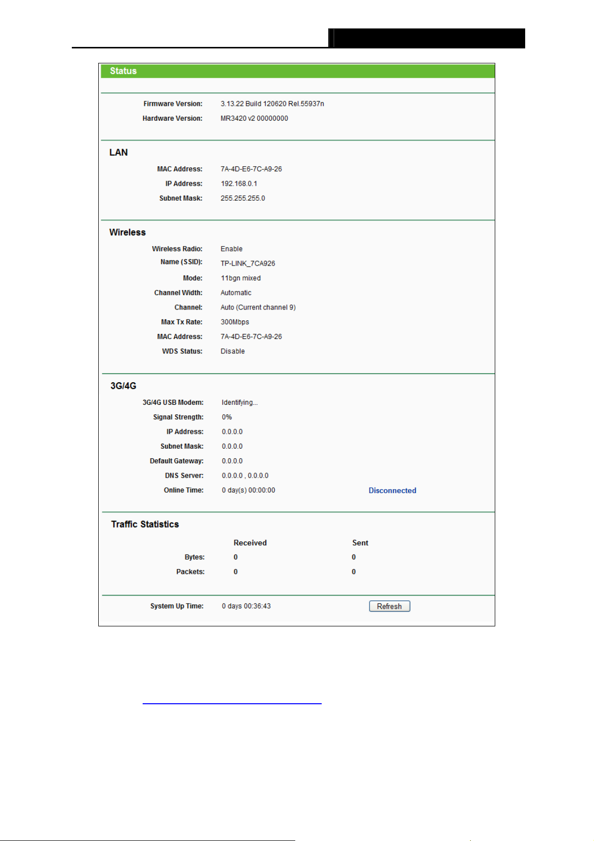
4.2 Status
The Status page displays the current status information about the Router. All information is
read-only.
-13-
TL-MR3420 3G/4G Wireless N Router User Guide
Figure 4-1 Status
4.3 Quick Setup
Please refer to Section 3.2: «Quick Installation Guide.»
4.4 WPS
This section will guide you to add a new wireless device to an existing network quickly by WPS
(Wi-Fi Protected Setup) function.
-14-
TL-MR3420 3G/4G Wireless N Router User Guide
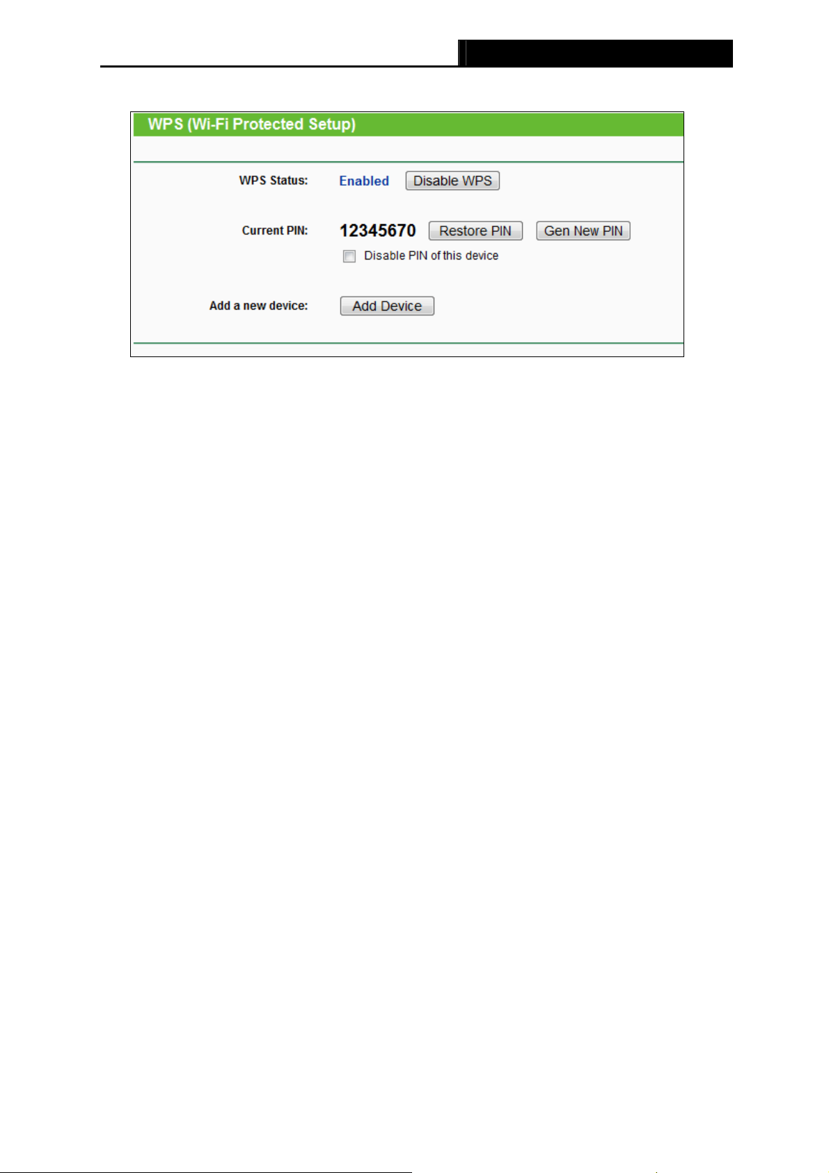
a). Choose menu “WPS”, you will see the next screen (shown in Figure 4-2).
Figure 4-2 WPS
WPS Status — Enable or disable the WPS function here.
Current PIN — The current value of the Router’s PIN displayed here. The default PIN of the
Router can be found in the label or User Guide.
Restore PIN — Restore the PIN of the Router to its default.
Gen New PIN — Click this button, and then you can get a new random value for the
Router’s PIN. You can ensure the network security by generating a new PIN.
Disable PIN of this device — WPS external registrar of entering this device’s PIN can be
disabled or enabled manually. If this device receives multiple failed attempts to
authenticate an external Registrar, this function will be disabled automatically.
Add Device — You can add the new device to the existing network manually by clicking
this button.
b). To add a new device:
If the wireless adapter supports Wi-Fi Protected Setup (WPS) or QSS (Quick Secure Setup),
you can establish a wireless connection between wireless adapter and Router by using either
Push Button Configuration (PBC) method or PIN method.
Note:
To build a successful connection by WPS, you should also do the corresponding configuration
of the new device for WPS function meanwhile.
For the configuration of the new device, here takes the Wireless adapter of our company for
example.
I. By PBC (Push Button Configuration)
If the wireless adapter supports Wi-Fi Protected Setup or Quick Secure Setup and the PBC
method, you can add it to the network by PBC with the following two methods.
Method One:
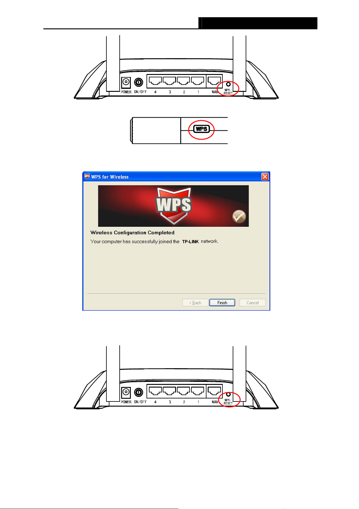
Step 1: Press the WPS/RESET button on the rear panel of the Router.
-15-
TL-MR3420 3G/4G Wireless N Router User Guide
Step 2: Press and hold the WPS or QSS button of the adapter directly for 2 or 3 seconds.
Step 3: Wait for a while until the next screen appears. Click Finish to complete the WPS
configuration.
The WPS Configuration Screen of wireless adapter
Method Two:
Step 1: Press the WPS/RESET button on the rear panel of the Router.
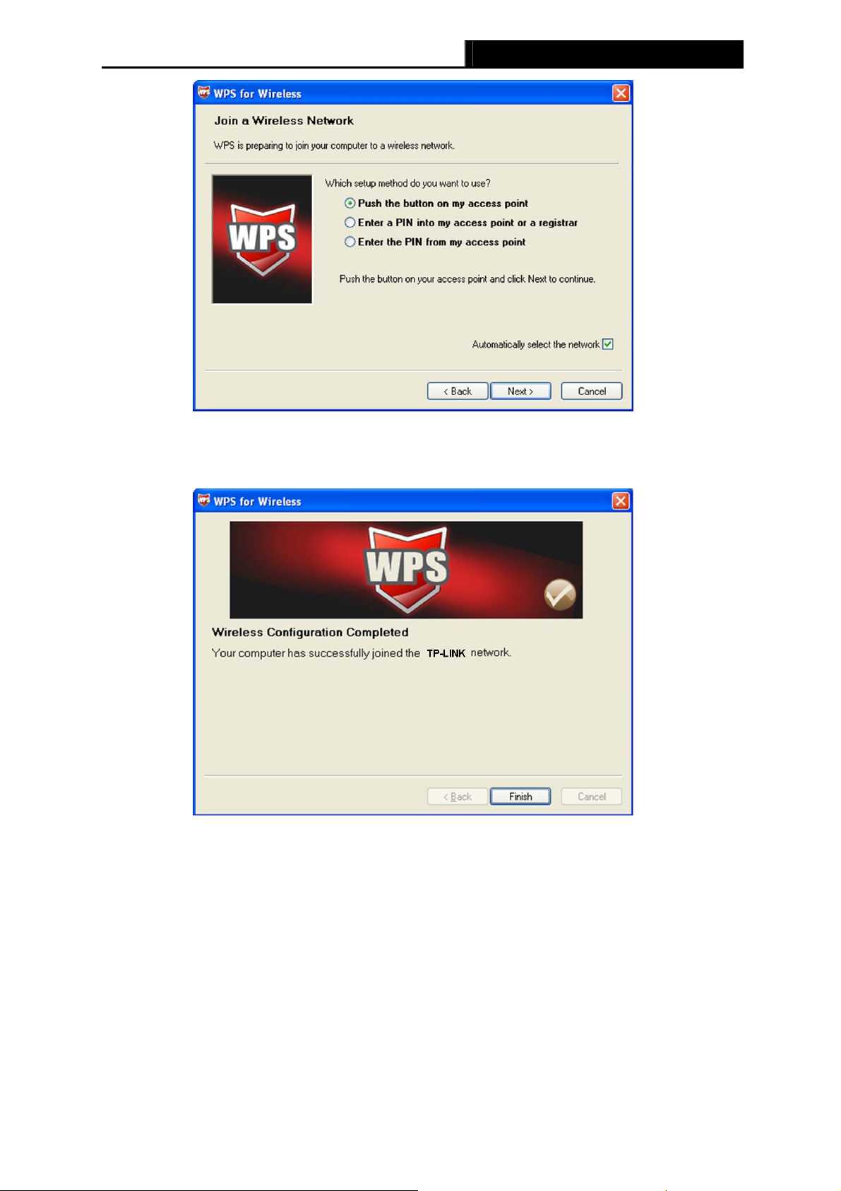
Step 2: For the configuration of the wireless adapter, please choose Push the button on my
access point in the configuration utility of the WPS as below, and click Next.
-16-
TL-MR3420 3G/4G Wireless N Router User Guide
The WPS Configuration Screen of wireless adapter
Step 3: Wait for a while until the next screen appears. Click Finish to complete the WPS
configuration.
The WPS Configuration Screen of wireless adapter
Method Three:
Step 1: Keep the default WPS Status as Enabled and click the Add device button in
Figure 4-2,
then the following screen will appear.
-17-
TL-MR3420 3G/4G Wireless N Router User Guide
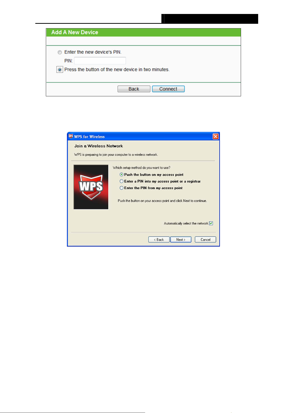
Figure 4-3 Add A New Device
Step 2: Choose Press the button of the new device in two minutes and click Connect.
Step 3: For the configuration of the wireless adapter, please choose Push the button on my
access point in the configuration utility of the WPS as below, and click Next.
The WPS Configuration Screen of Wireless adapter
Step 4: Wait for a while until the next screen appears. Click Finish to complete the WPS
configuration.
-18-
II. By PIN
TL-MR3420 3G/4G Wireless N Router User Guide
The WPS Configuration Screen of Wireless adapter
If the wireless adapter supports Wi-Fi Protected Setup or Quick Secure Setup and the PIN
method, you can add it to the network by PIN with the following two methods.
Method One: Enter the PIN into my Router
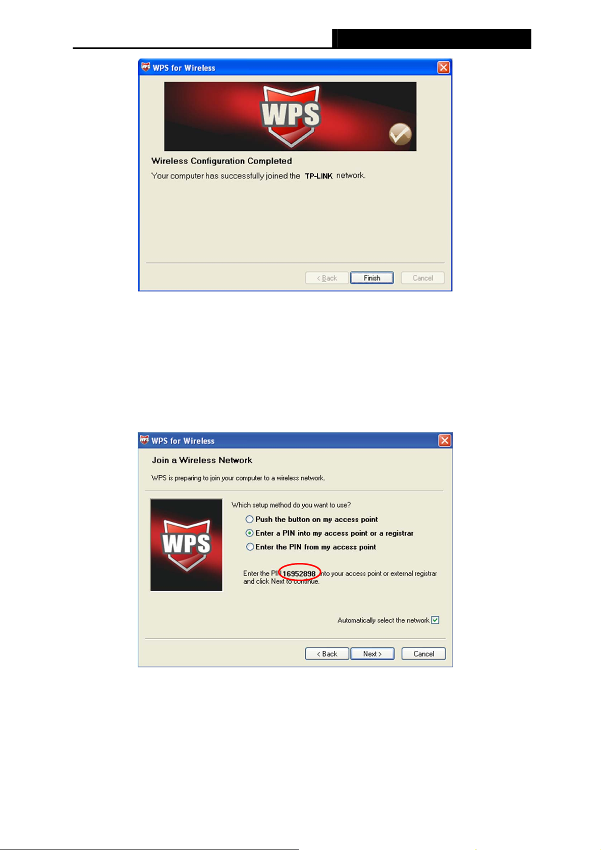
Step 1: Configure the wireless adapter. Please choose Enter a PIN into my access point or a
registrar in the configuration utility of the WPS as below, and click Next.
The WPS Configuration Screen of wireless adapter
Note:
In this example, the default PIN code of this adapter is 16952898 as the above figure shown.
Step 2: Configure the Router TL-MR3420. Keep the default WPS Status as Enabled and click
the Add device button in
Figure 4-2, then the following screen will appear.
-19-
TL-MR3420 3G/4G Wireless N Router User Guide
Step 3: Choose Enter the new device’s PIN and enter the PIN code of the wireless adapter in
the field behind PIN in the previous figure. Then click Connect.
Note:
The PIN code of the wireless adapter is always displayed on the WPS or QSS configuration
screen.
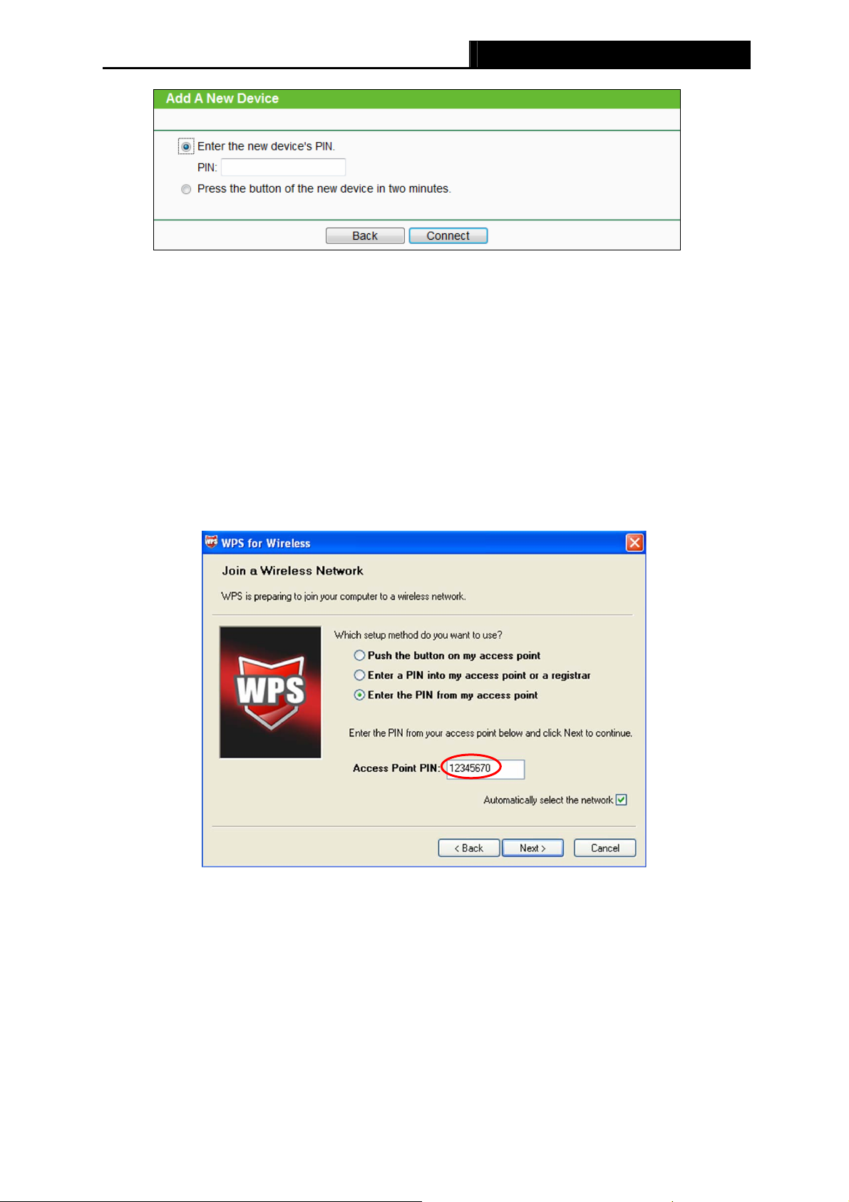
Method Two: Enter the PIN from my Router
Step 1: Get the Current PIN code of the Router in
code. Here takes the PIN code 12345670 of this Router for example).
Step 2: For the configuration of the wireless adapter, please choose Enter a PIN from my
access point in the configuration utility of the WPS as below, and enter the PIN code
of the Router into the field behind Access Point PIN. Then click Next.
Figure 4-2 (each Router has its unique PIN
The WPS Configuration Screen of Wireless adapter
Note:
The default PIN code of the Router can be found in its label or the WPS configuration screen as
Figure 4-2.
-20-
TL-MR3420 3G/4G Wireless N Router User Guide
c). You will see the following screen when the new device successfully connected to the
network.
Note:
1) The status LED on the Router will light green all the time if the device has been
successfully added to the network.
2) The WPS function cannot be configured if the Wireless Function of the Router is disabled.
Please make sure the Wireless Function is enabled before configuring the WPS.
4.5 Network
Figure 4-4 the Network menu
There are five submenus under the Network menu ( as shown in Figure 4-4): Internet Acc
3G/4G, WAN, MAC Clone and LAN. Click any of them, and you will be able to configure the
corresponding function.
ess,
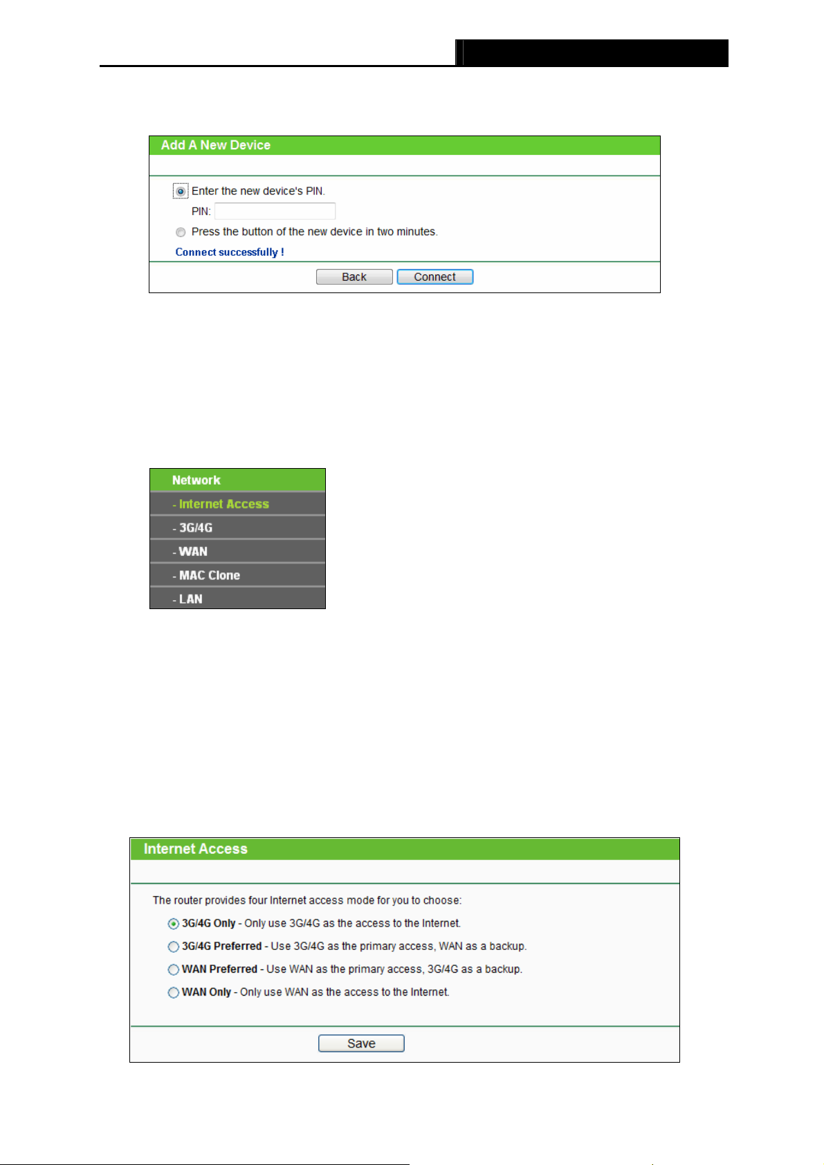
4.5.1 Internet Access
Choose menu “Network→Internet Access”, you can configure the access mode on the screen
below. The Router is designed to work with either WAN port or 3G/4G USB modem, and
supports “automatically take over back up with 3G/4G access” as Ethernet WAN failover.
Figure 4-5 Internet Access
-21-
Loading…

Юрий Санаев
Системный администратор. Менеджер по продажам компьютеров и wi-fi оборудования. Опыт работы – 10 лет. Знает о «железе» и софте все и даже больше.
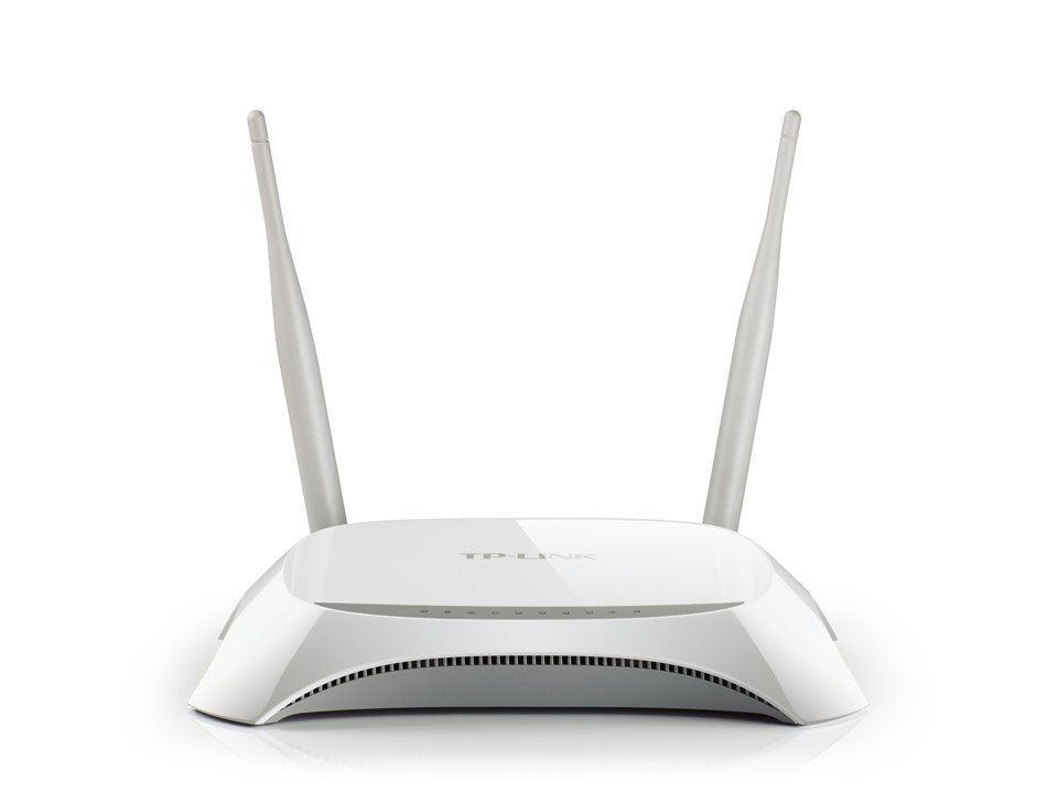
TP-Link TL-MR3420 – недорогой маршрутизатор от известного производителя с широким функционалом и высокой скоростью передачи данных до 300 Мбит/с, достаточной для просмотра фильмов онлайн или загрузки больших файлов. Среди его особенностей – две антенны для быстрой передачи сигнала и обеспечения большой площади покрытия и разъем USB для подключения флешек, жестких дисков или 3G/4G модемов. О характеристиках и возможностях прибора, подключении и настройке расскажем в этом обзоре.

Содержание
- Характеристики
- Обзор индикаторов и разъемов
- Подключение роутера
- Вход в веб-интерфейс
- Быстрая настройка
- Ручная настройка
- IPTV
- Изменение заводского пароля
- Прошивка
- Отзывы
Характеристики
Технические характеристики у TP-Link TL-MR3420 – одни из лучших в бюджетном ценовом сегменте.
| Разъемы | 1 USB, 1 WAN, 4 LAN |
| Кнопки | Reset/WPS, Wi-Fi, Power |
| Антенны | 2, несъемные, коэффициент усиления 5 дБи |
| Беспроводные сети | IEEE 802.11 b/g/n |
| Диапазон частот | 2400-2483,5 МГц |
| Скорость соединения | До 300 Мбит/с |
Маршрутизатор ТП-Линк ТЛ-МР3420 выпущен в двух аппаратных версиях. Вторая получила обновленный дизайн и поддержку 4G. Информация в статье относится именно к этой модели.
Удобство и простота настройки
9
Модель той же марки с близкими техническими характеристиками – TP-LINK TL-MR3220.
Обзор индикаторов и разъемов
Роутер TP-Link выглядит стильно благодаря плавным линиям корпуса. Верхняя часть выполнена из белого глянцевого пластика, нижняя – из матового серого. На верхней панели находится ряд индикаторов, светящихся зеленым цветом:
- Power: горит – прибор включен, не горит – выключен;
- System: светится – запуск маршрутизатора, мигает – нормальная работа, не светится – сбой устройства;
- WLAN: горит – Wi-Fi включен, не горит – Wi-Fi выключен;
- WAN: светится – к маршрутизатору подключен кабель, мигает – идет передача данных, не светится – кабель отключен;
- LAN 1-4: горит – к соответствующему порту подключен клиент, мигает – идет передача данных, не горит – нет подключенных устройств;
- USB: светится – подключен 3G/4G модем, мигает – идет передача данных, не светится – нет подключенных устройств;
- WPS: мигает – беспроводное устройство подключается к сети, продолжительность до 2 минут, постоянно горит – клиент добавлен в сеть, не горит – WPS отключена, быстро мигает – сбой при добавлении устройства в сеть.
На боковой панели роутера размещен разъем USB. Это удачное решение – подключить модем или флешку сбоку удобнее, чем к порту на тыльной стороне. Рядом с USB входом находится кнопка включения/выключения Wi-Fi.

На задней панели расположены разъем для подключения сетевого адаптера, кнопка питания, 4 пронумерованных разъема LAN желтого цвета, порт WAN синего цвета, кнопка RESET/WPS.
В комплекте с устройством производитель поставляет адаптер питания, руководство пользователя, диск с программным обеспечением, коммутационный кабель.
Подключение роутера
Перед подключением роутер должен быть правильно размещен в помещении. Если используется кабельное соединение, маршрутизатор устанавливают поблизости от системного блока компьютера. При беспроводном подключении роутер рекомендуется разместить так, чтобы он находился посредине квартиры или дома. Так будет обеспечено равномерное покрытие сигналом всего помещения. При необходимости устройство крепят на стене с помощью отверстий на нижней стороне.

После установки кабель от поставщика подсоединяют к разъему WAN маршрутизатора TP-Link TL-MR3420 V2, коммутационный кабель от разъема LAN роутера – к аналогичному порту на системном блоке ПК или ноутбука. Далее нужно подключить адаптер питания, вставить в розетку и нажать на кнопку «Power» для запуска устройства.
Вход в веб-интерфейс
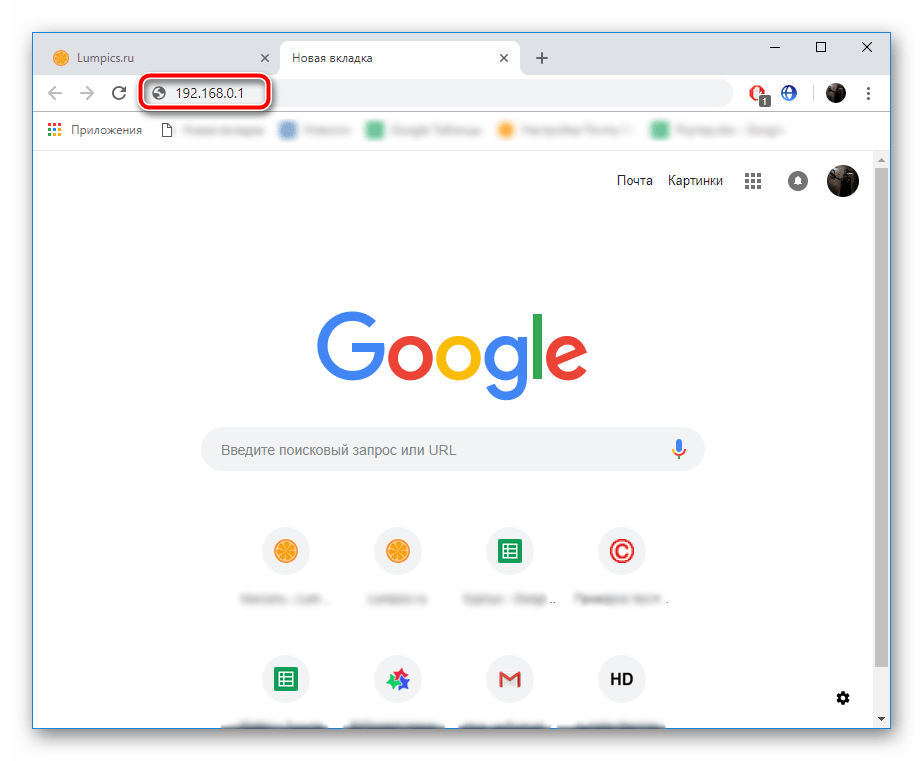
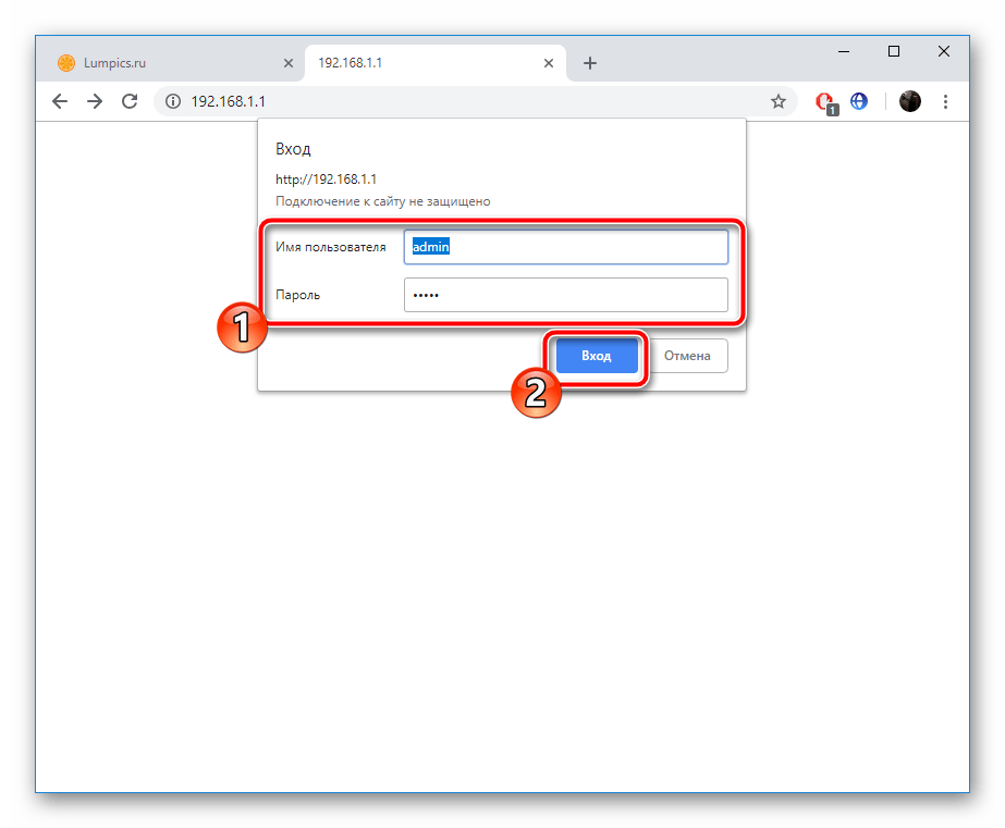
Настройка роутера TP-Link TL-MR3420 выполняется через веб-интерфейс. Чтобы открыть его, нужно запустить браузер и в адресной строке ввести 192.168.0.1. Появится окно ввода логина и пароля. По умолчанию это «admin/admin».
Быстрая настройка
Практически все маршрутизаторы TP-Link, включая и TL-MR3420, имеют мастер быстрой настройки. Он позволяет легко установить интернет-соединение, меняя только основные параметры.
Инструкция:
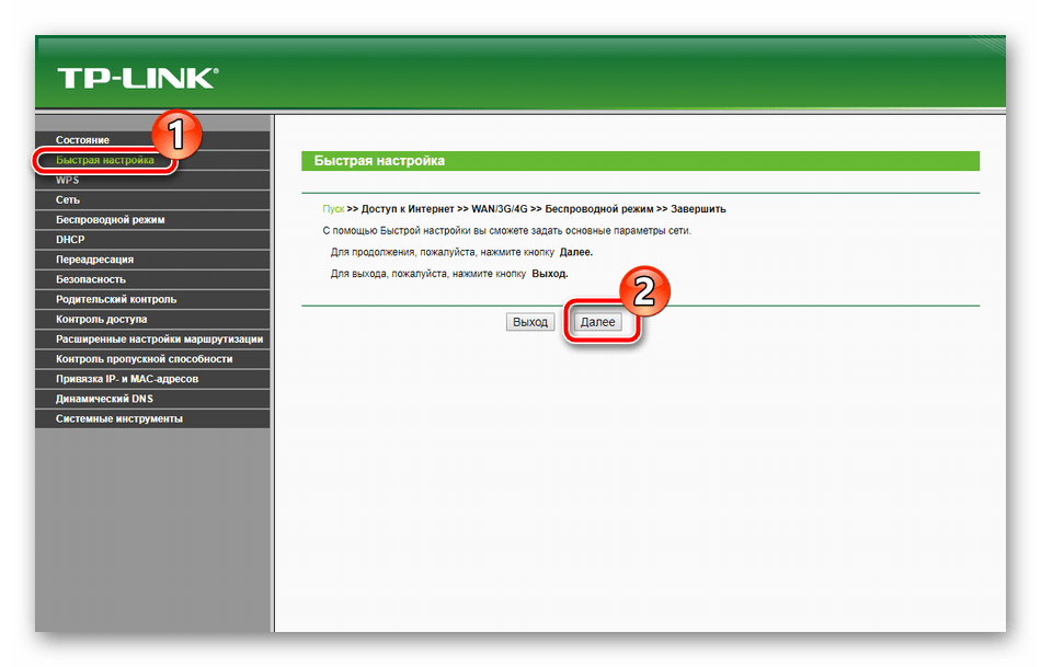
- Открыть веб-интерфейс роутера, нажать «Быстрая настройка».


- Кликнуть «Далее».

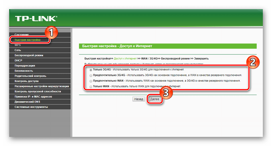
- Выбрать тип подключения – «Только WAN».

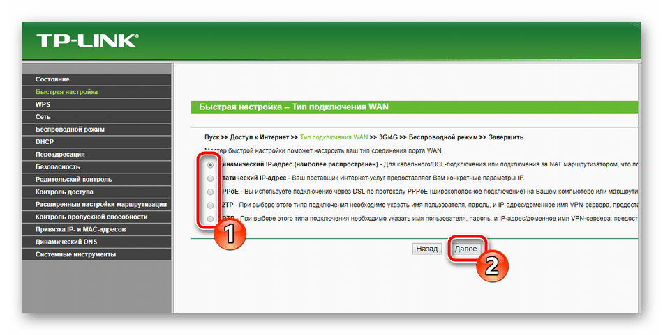
- Указать тип соединения, при необходимости уточнить информацию у провайдера. Чаще всего используется «Динамический IP-адрес».

- При выборе «Статического IP-адреса» нужно вручную указать IP, маску подсети, шлюз, первичный и вторичный DNS, предварительно получив данные у поставщика услуг.
- Выбрать клонирование MAC-адреса.
- Если нужно настроить беспроводную сеть, выбрать «Включить», указать имя сети, установить защиту «WPA-PSK/WPA2-PSK», придумать и ввести надежный пароль.


На экране появится уведомление об успешной настройке подключения.
Ручная настройка
Ручная настройка маршрутизатора TP-Link TL-MR3420 дает возможность настроить работу устройства под свои потребности с помощью дополнительных инструментов и функций.
Инструкция:
- Открыть веб-интерфейс, в меню слева выбрать «Сеть», нажать «Доступ в Интернет».
- Установить необходимый режим или комбинацию, если используется несколько типов подключения. Роутер будет самостоятельно переключаться между ними.
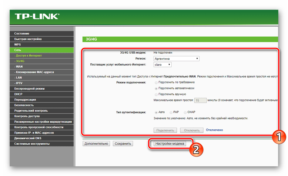
- Если настраивается подключение через USB-модем: выбрать вкладку «3G/4G», определить регион, мобильного оператора, указать способ подключения. Сохранить изменения.
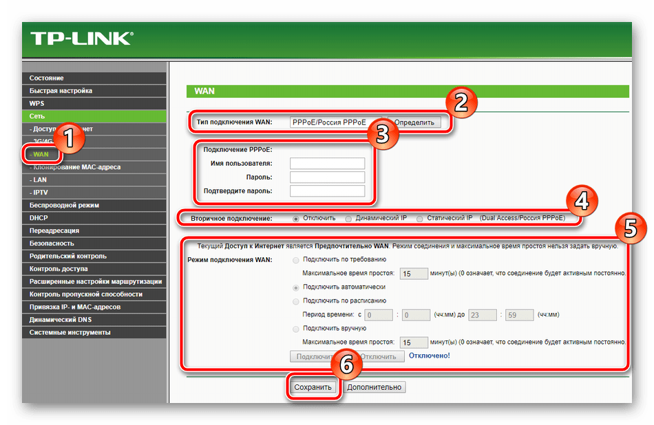
- Настроить основное подключение WAN: открыть вкладку «WAN», выбрать «Тип подключения», заполнить данные для статического или других типов подключения.
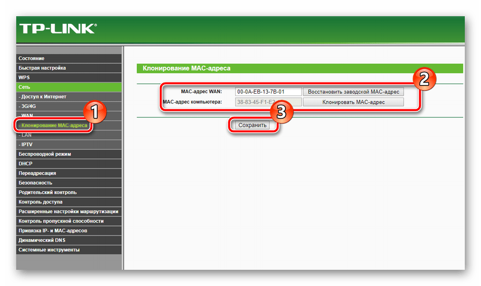
- Выполнить клонирование MAC-адреса.
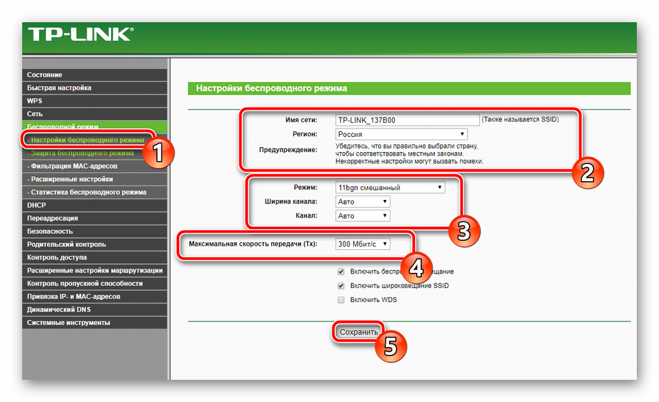
- Открыть раздел «Беспроводная сеть», перейти во вкладку «Настройки беспроводного режима». Указать имя сети, регион. Режим и ширину канала не трогать. При необходимости установить максимальную скорость передачи.

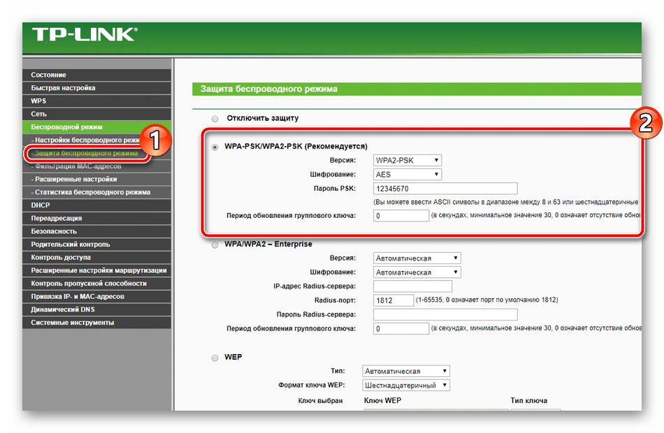
- Перейти в раздел «Защита беспроводного режима». Включить «WPA-PSK», установить надежный пароль.
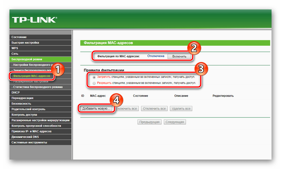
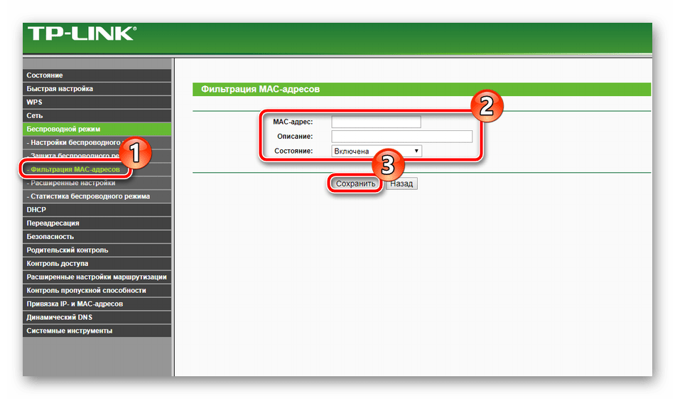
- Открыть «Фильтрацию MAC-адресов». Здесь можно запретить или разрешить определенным устройствам подключаться к сети. Включить фильтрацию, нажать «Добавить новую», ввести MAC-адрес устройства, добавить описание, выбрать тип разрешения, нажать «Сохранить».


Процесс настройки занимает всего несколько минут, после чего доступ к Интернету будет получен и надежно защищен.
IPTV
Маршрутизатор TP-Link TL-MR3420 позволяет просматривать интерактивное телевидение, но предлагает минимальный набор настроек для редактирования. Инструкция:
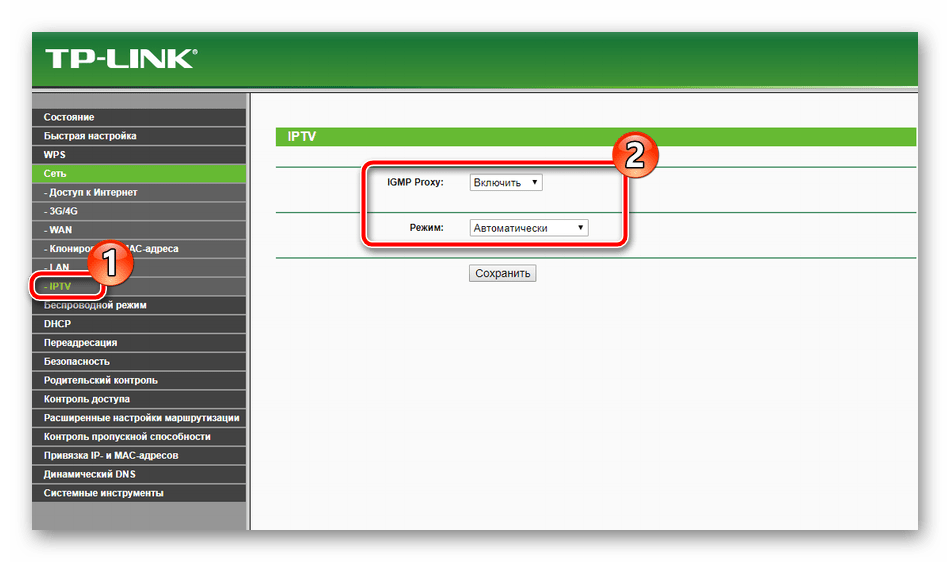
- Открыть веб-интерфейс, перейти в раздел «Сеть» и выбрать вкладку «IPTV».
- Напротив IGMP Proxy нажать «Включить».
- Установить режим «Мост» как наиболее часто используемый.
- Выбрать порт для подключения приставки – только «LAN 4» или «LAN 3 & LAN 4».
- Сохранить изменения.

После этих действий IPTV будет доступно на всех устройствах – телефонах, планшетах, ПК, ноутбуках, смарт-телевизорах после установки специальных приложений.
Для некоторых провайдеров нужно:
- Выбрать режим «802.1Q TAG VLAN».
- Установить «Отключить» напротив «VLAN TAG для Интернет».
- Прописать «Идентификатор VLAN для услуги IPTV», предварительно получив значение от провайдера.
- Выбрать порт, в который подключена приставка.
- Нажать «Сохранить».


Второй способ иногда встречается у Ростелекома.
Изменение заводского пароля
Чтобы защитить веб-интерфейс маршрутизатора от посторонних лиц и исключить их вмешательство в настройки, нужно изменить заводской пароль на более сложный. Инструкция:
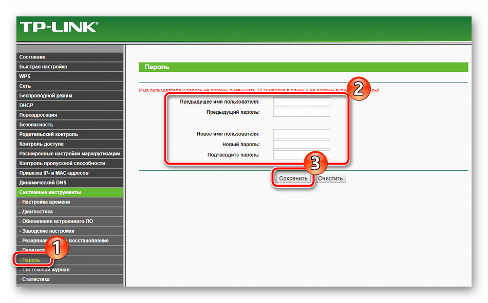
- Открыть веб-интерфейс, перейти во вкладку «Системные инструменты», выбрать «Пароль».
- Ввести предыдущие имя пользователя и пароль – по умолчанию «admin/admin».
- Указать новые логин и пароль.
- Нажать «Сохранить».
Новые учетные данные не должны быть длиннее 14 символов и не могут включать в себя пробелы.

Прошивка
После подключения и настройки рекомендуется обновить прошивку TP-Link TL-MR3420 до актуальной. В каждой «свежей» версии программного обеспечения разработчики устраняют обнаруженные ошибки и добавляют новые функции, поэтому нужно регулярно проводить поиск новых прошивок и их установку.
Инструкция:
- Открыть веб-интерфейс, перейти в «Системные инструменты» и выбрать «Обновление встроенного ПО».
- Посмотреть и запомнить текущую версию ПО.

- Открыть сайт производителя по ссылке https://www.tp-link.com/ru/support/download/tl-mr3420/v2/. На этой странице можно скачать краткую или подробную инструкцию на русском языке к TL-MR3420.
- Нажать «Встроенное ПО».

- Пролистать страницу вниз, найти последнюю версию прошивки, сравнить с установленной. Если ПО на сайте новее, нажать на кнопку загрузки и выбрать путь для скачивания файла.
- Вернуться в веб-интерфейс, нажать «Выберите файл» и указать папку с загруженной прошивкой.
- Нажать «Обновить».


Когда обновление будет завершено, роутер автоматически перезагрузится.
Чтобы не нанести урон маршрутизатору, не обновляйте его по Wi-Fi. Беспроводное подключение менее стабильно, чем кабельное. Обрыв соединения может привести к поломке устройства.
В процессе обновления запрещено выключать маршрутизатор, чтобы не причинить ему вред.
Итак, TP-link TL-MR3420 – надежный бюджетный маршрутизатор с поддержкой 3G/4G модемов. Он предлагает скорость интернет-соединения до 300 Мбит/с и широкую площадь покрытия благодаря двум антеннам. Устройство выделяется простотой настройки – интуитивно понятный веб-интерфейс дает возможность даже начинающим пользователям самостоятельно установить подключение к Интернету. С точки зрения функциональности и надежности этот роутер является одним из лучших устройств в бюджетной ценовой категории.
Отзывы
Большинство отзывов о роутере TP-link TL-MR3420 положительные. Ниже вы можете ознакомиться с ними.
Все способы:
- Подготовка к настройке
- Настраиваем роутер TP-Link TL-MR3420
- Быстрая настройка
- Ручная настройка
- Дополнительные настройки
- Настройки безопасности
- Завершение настройки
- Вопросы и ответы: 0
При покупке нового сетевого оборудования обязательным шагом является его настройка. Осуществляется она через микропрограммное обеспечение, созданное производителями. В процесс конфигурации входит отладка проводного соединения, точки доступа, параметров безопасности и дополнительных возможностей. Далее мы детально расскажем об этой процедуре, взяв за пример маршрутизатор TP-Link TL-MR3420.
Подготовка к настройке
После распаковки роутера возникает вопрос, в какое место его установить. Выбирать расположение следует исходя из длины сетевого кабеля, а также зоны действия беспроводной сети. По возможности лучше избегать наличия рядом приборов типа микроволновой печи и учитывать, что преграды в виде, например, толстых стен, снижают качество сигнала Wi-Fi.
Поверните маршрутизатор задней панелью к себе, чтобы ознакомиться со всеми присутствующими в нем разъемами и кнопками. WAN обозначен синим цветом, а Ethernet 1-4 – желтым. В первый подключается кабель от провайдера, а в остальные четыре все присутствующие дома или в офисе компьютеры.
Неправильно выставленные сетевые значения в операционной системе часто приводят к неработоспособности проводного соединения или точки доступа. Перед началом выполнения поставленной задачи конфигурирования оборудования загляните в параметры Windows и убедитесь, что значения для протоколов DNS и IP получаются автоматически. Детальные инструкции на эту тему ищите в другой нашей статье по ссылке ниже.
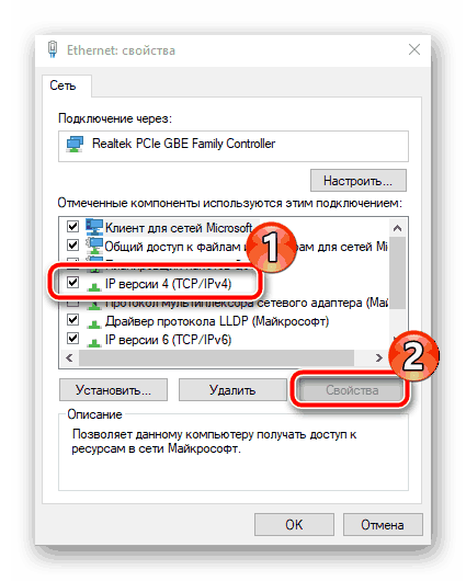
Подробнее: Сетевые настройки Windows 7
Настраиваем роутер TP-Link TL-MR3420
Все руководства, приведенные ниже, осуществляются через веб-интерфейс второй версии. Если у вас не совпадает внешний вид микропрограммного обеспечения с тем, что используется в этой статье, просто отыщите такие же пункты и измените их по нашим примерам, функционально прошивки рассматриваемого роутера практически не отличаются. Вход в интерфейс на всех версиях происходит следующим образом:
- Откройте любой удобный веб-обозреватель и напечатайте в адресной строке
192.168.1.1или192.168.0.1, после чего нажмите на клавишу Enter. - В отобразившейся форме в каждой строке введите
adminи подтвердите вход.
Теперь перейдем непосредственно к самой процедуре конфигурирования, которая происходит в двух режимах. Кроме этого мы затронем дополнительные параметры и инструменты, что будет полезно многим юзерам.
Быстрая настройка
Практически каждое микропрограммное обеспечение роутеров TP-Link содержит встроенный Мастер настройки, и рассматриваемая модель не стала исключением. С его помощью изменяются только самые основные параметры проводного соединения и точки доступа. Для успешного выполнения поставленной задачи вам нужно осуществить следующее:
- Откройте категорию «Быстрая настройка» и сразу кликните на «Далее», это запустит Мастера.
- Сначала корректируется доступ в интернет. Вам предлагается выбрать один из типов WAN, который преимущественно и будет задействован. Большинство выбирают «Только WAN».
- Далее задается тип подключения. Определяется этот пункт непосредственно самим провайдером. Информацию на эту тему ищите в договоре с поставщиком интернет-услуг. Там указаны все данные для ввода.
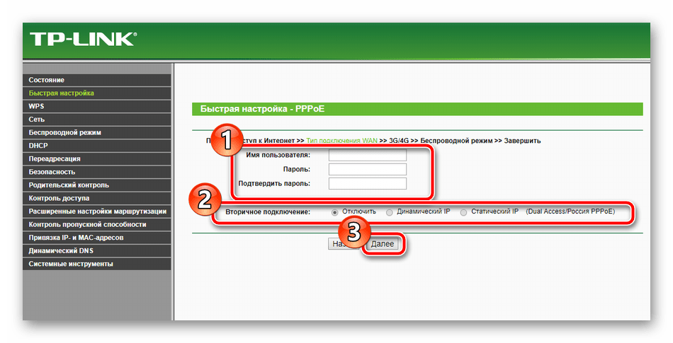
- Некоторые интернет-соединения работают нормально только после активации пользователя, а для этого необходимо задать логин и пароль, полученные при заключении договора с провайдером. Кроме этого вы можете выбрать вторичное подключение, если такое нужно.
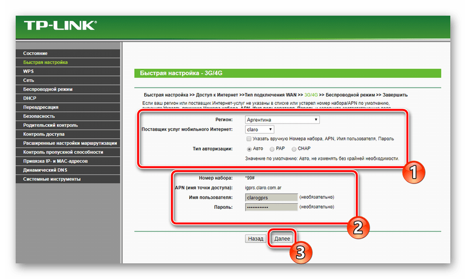
- В случае когда вы на первом этапе указали, что также будет использоваться 3G/4G, в отдельном окне потребуется выставить основные параметры. Укажите правильный регион, поставщика мобильного интернета, тип авторизации, имя пользователя и пароль, если это необходимо. По завершении кликните на «Далее».
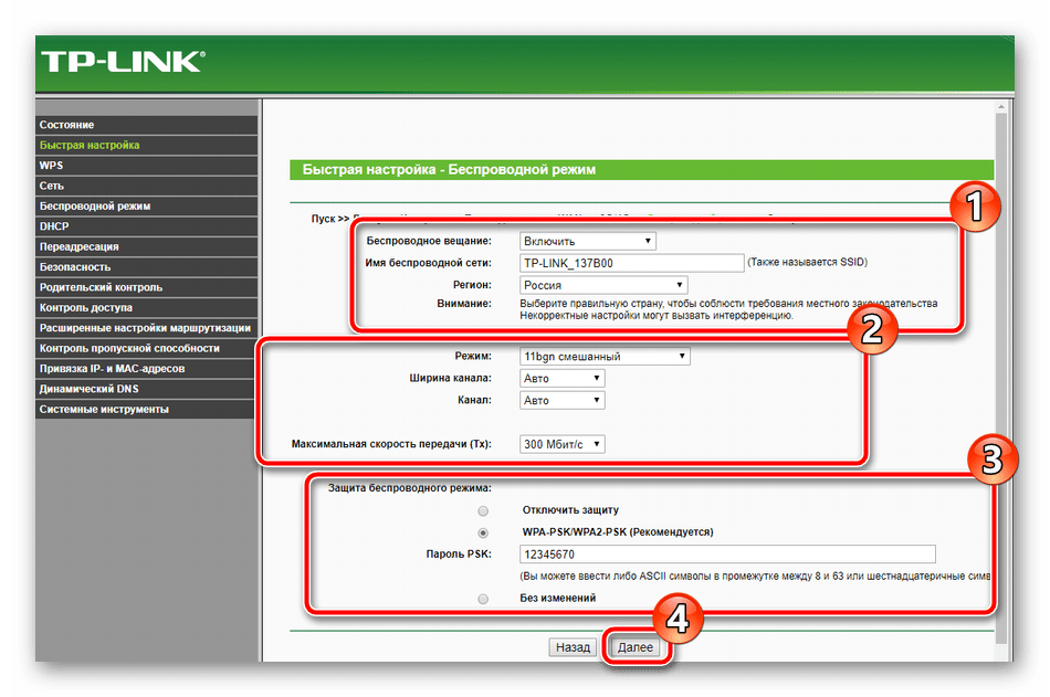
- Последним шагом является создание беспроводной точки, которую задействуют большинство юзеров для получения доступа к интернету со своих мобильных девайсов. В первую очередь активируйте сам режим и задайте имя для своей точки доступа. С ним она будет отображаться в списке соединений. «Режим» и «Ширина канала» оставьте по умолчанию, а вот в разделе про безопасность поставьте маркер возле «WPA-PSK/WPA2-PSK» и укажите удобный пароль, состоящий минимум из восьми символов. Его необходимо будет ввести каждому пользователю при попытке подключения к вашей точке.
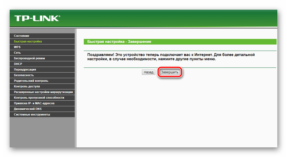
- Перед вами отобразится уведомление, что процедура быстрой настройки прошла успешно, выйти из Мастера можно нажатием на кнопку «Завершить».
Однако предоставляемые параметры при быстрой настройке не всегда отвечают потребностям пользователей. В таком случае лучшим решением будет перейти к соответствующему меню в веб-интерфейсе и вручную задать все необходимое.
Ручная настройка
Многие пункты ручного конфигурирования похожи на те, что рассматривались во встроенном Мастере, однако здесь появляется большее количество дополнительных функций и инструментов, что позволяет корректировать систему индивидуально под себя. Начнем разбор всего процесса с проводного соединения:
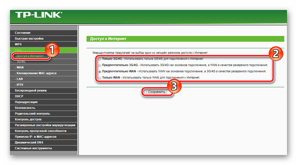
- Откройте категорию «Сеть» и переместитесь в раздел «Доступ в интернет». Перед вами открывается копия первого этапа из быстрой настройки. Задайте здесь тот тип сети, который вы будете использовать наиболее часто.
- Следующим подразделом является «3G/4G». Обратите внимание на пункты «Регион» и «Поставщик услуг мобильного интернета». Все остальные значения выставляйте исключительно под свои нужды. Кроме этого вы можете загрузить конфигурацию модема, если такая имеется у вас на компьютере в виде файла. Для этого кликните на кнопку «Настройка модема» и выберите файл.
- Теперь остановимся на WAN – основное сетевое подключение, использующееся большинством обладателей подобного оборудования. Первым шагом является переход в раздел «WAN», затем выбирается тип соединения, задается имя пользователя и пароль, если это требуется, а также вторичная сеть и параметры режима. Все присутствующие в этом окне пункты заполняются в соответствии с договором, полученным у провайдера.
- Иногда требуется выполнить клонирование MAC-адреса. Обсуждается данная процедура предварительно с поставщиком интернет-услуг, а затем через соответствующий раздел в веб-интерфейсе происходит замена значений.
- Последним пунктом является «IPTV». Роутер TP-Link TL-MR3420 хоть и поддерживает такую услугу, однако предоставляет скудный набор параметров для редактирования. Вы можете только изменить значение Proxy и тип работы, что требуется крайне редко.
На этом отладка проводного соединения закончена, однако немаловажной частью также считается и беспроводная точка доступа, которая создается юзером вручную. Подготовка к работе с беспроводным подключением выполняется так:
- В категории «Беспроводной режим» выберите «Настройки беспроводного режима». Пройдемся по всем присутствующим пунктам. Сначала задайте имя сети, оно может быть любое, затем укажите свою страну. Режим, ширина канала и сам канал часто остаются неизменными, поскольку их ручная настройка требуется крайне редко. Кроме того, вам доступна установка ограничений на максимальную скорость передачи данных на вашей точке. По завершении всех действий кликните на «Сохранить».
- Соседним разделом является «Защита беспроводного режима», куда вам и следует перейти далее. Отметьте маркером рекомендованный тип шифрования и измените там только ключ, который будет служить паролем к вашей точке.
- В разделе «Фильтрация MAC-адресов» задаются правила этого инструмента. Он позволяет ограничить или, наоборот, разрешить определенным устройствам подключаться к вашей беспроводной сети. Для этого активируйте функцию, установите желаемое правило и нажмите на «Добавить новую».
- В открывшемся окне вам будет предложено ввести адрес необходимого устройства, дать ему описание и выбрать состояние. После завершения сохраните изменения кликом на соответствующую кнопку.
На этом работа с основными параметрами завершена. Как видите, в этом нет ничего сложного, весь процесс занимает буквально несколько минут, после чего можно сразу приступать к работе в интернете. Однако присутствуют еще дополнительные инструменты и политики безопасности, что также необходимо рассмотреть.
Дополнительные настройки
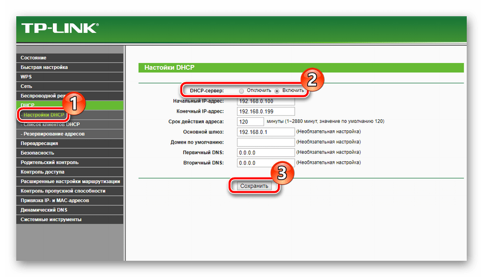
В первую очередь разберем раздел «Настройки DHCP». Данный протокол позволяет автоматически получать определенные адреса, за счет чего сеть работает более стабильно. Следует лишь убедиться в том, что функция включена, если же нет, отметьте маркером необходимый пункт и кликните на «Сохранить».
Иногда требуется пробросить порты. Их открытие позволяет локальным программам и серверам пользоваться интернетом и обмениваться данными. Процедура проброса выглядит так:
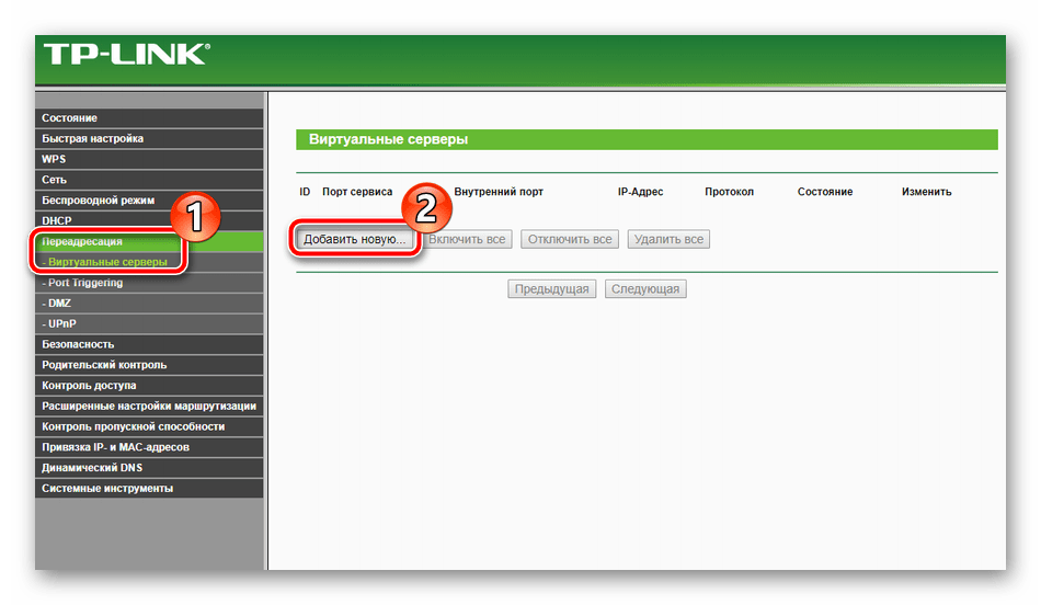
- Через категорию «Переадресация» перейдите в «Виртуальные серверы» и нажмите на «Добавить новую».
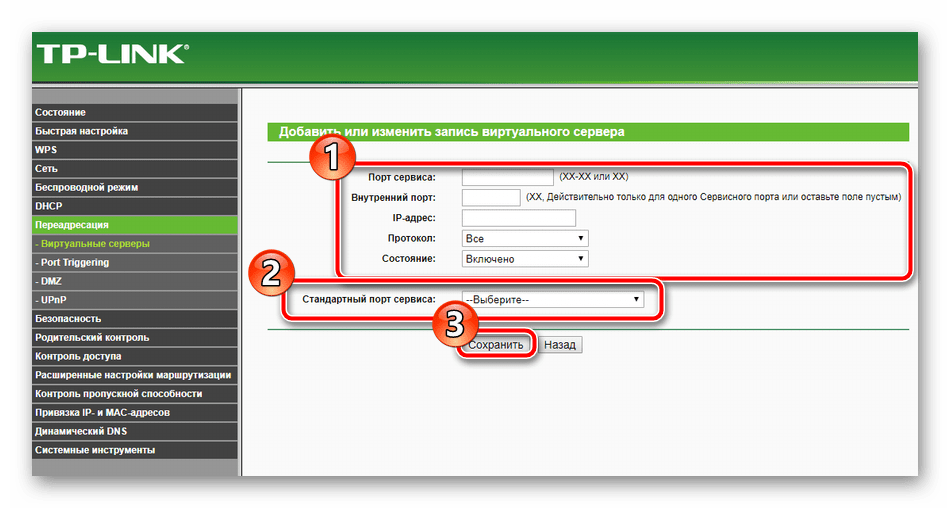
- Заполните открывшуюся форму в соответствии со своими требованиями.
Детальные инструкции по открытию портов на роутерах TP-Link вы можете найти в другой нашей статье по ссылке ниже.
Подробнее: Открытие портов на роутере TP-Link
Иногда при использовании VPN и других подключений происходит сбой при попытке маршрутизации. Случается это чаще всего из-за того, что сигнал проходит через специальные туннели и часто теряется. При возникновении подобной ситуации для требуемого адреса настраивается статический (прямой) маршрут, а выполняется это так:
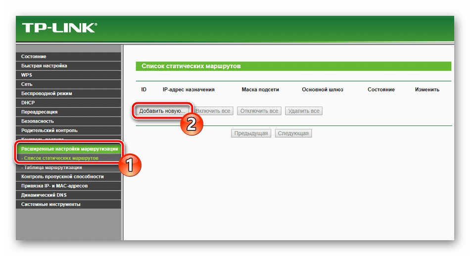
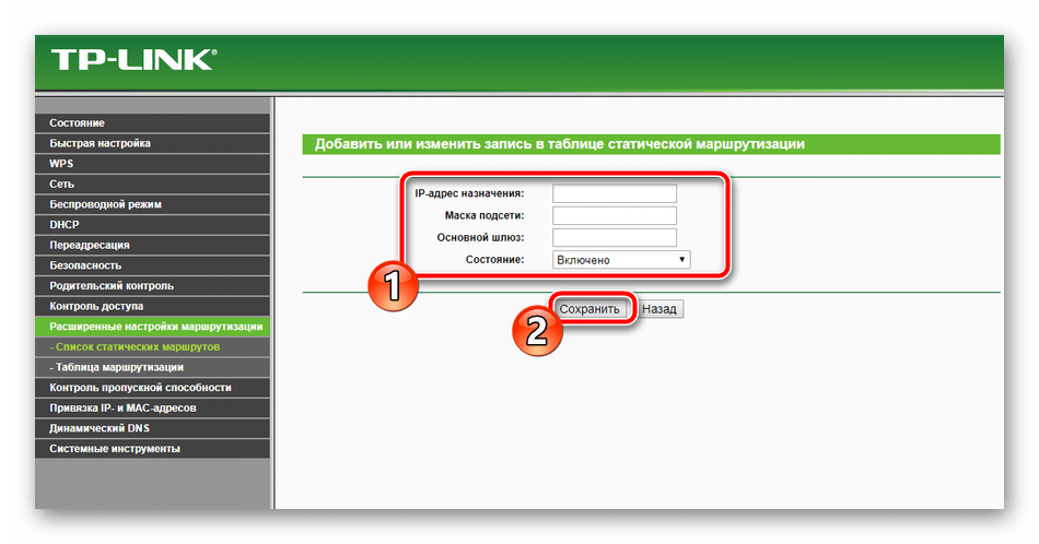
- Перейдите в раздел «Расширенные настройки маршрутизации» и выберите пункт «Список статических маршрутов». В открывшемся окне кликните на «Добавить новую».
- В строках укажите адрес назначения, сетевую маску, шлюз и задайте состояние. По завершении не забудьте нажать на «Сохранить», чтобы изменения вступили в силу.
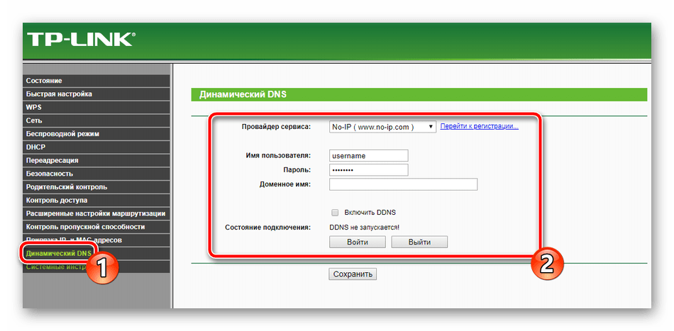
Последнее, что хотелось бы отметить из дополнительных настроек – Динамический DNS. Она необходима только в случае использования различных серверов и FTP. По умолчанию эта услуга отключена, а о ее предоставлении договариваются с провайдером. Он регистрирует вас на сервисе, присваивает имя пользователя и пароль. Активировать эту функцию вы можете в соответствующем меню настроек.
Настройки безопасности
Важно не только обеспечить корректное функционирование интернета на роутере, но и задать параметры безопасности, чтобы защитить себя от нежелательных подключений и шокирующего контента в сети. Мы рассмотрим самые основные и полезные правила, а вы уже решайте, нужно ли вам их активировать или нет:
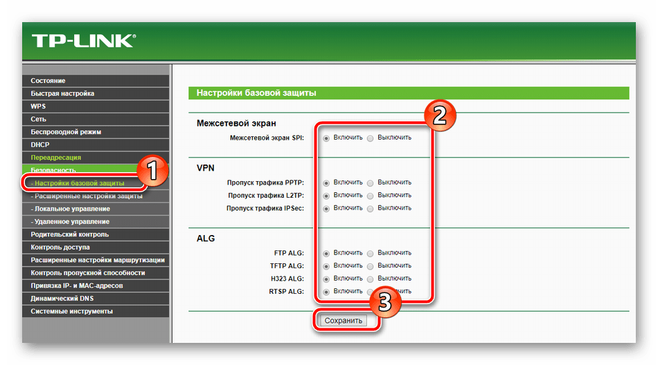
- Сразу обратите внимание на раздел «Настройки базовой защиты». Убедитесь в том, что все параметры здесь включены. Обычно они активны уже по умолчанию. Ничего отключать здесь не нужно, на саму работу устройства эти правила не влияют.
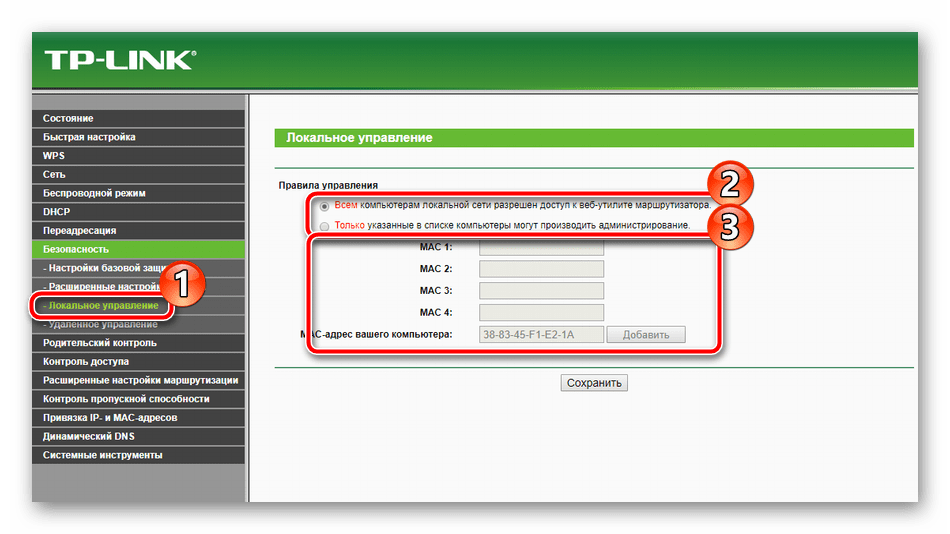
- Управление веб-интерфейсом доступно все пользователям, которые соединены с вашей локальной сетью. Запретить вход в микропрограммное обеспечение можно через соответствующую категорию. Здесь выберите подходящее правило и присвойте его для всех необходимых MAC-адресов.
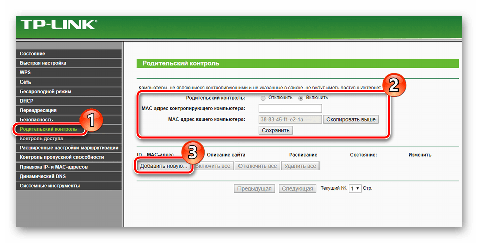
- Родительский контроль позволяет не только установить ограничение на время пребывания детей в интернете, но и задать запреты на определенные ресурсы. Сначала в разделе «Родительский контроль» активируйте эту функцию, введите адрес того компьютера, который хотите контролировать, и нажмите на «Добавить новую».
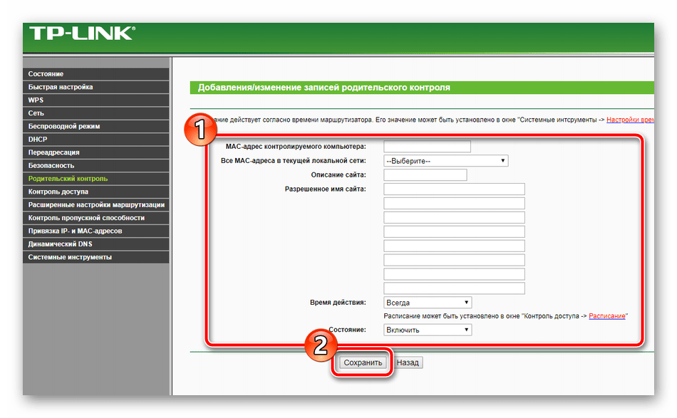
- В открывшемся меню установите те правила, которые посчитаете нужными. Повторите эту процедуру для всех требуемых сайтов.
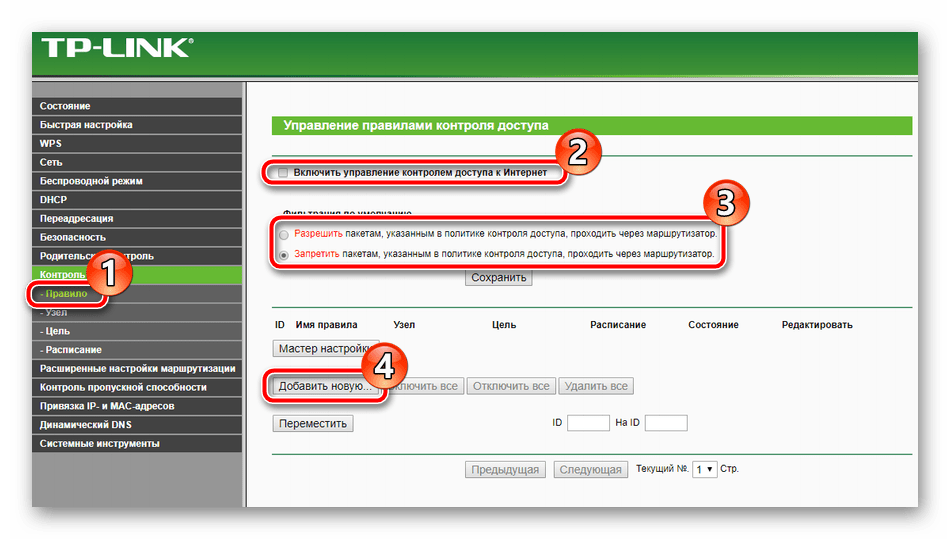
- Последнее, что хотелось бы отметить по безопасности – управление правилами контроля доступа. Через маршрутизатор проходит довольно большое количество различных пакетов и иногда требуется осуществлять контроль над ними. В таком случае перейдите в меню «Контроль» — «Правило», включите данную функцию, установите значения фильтрации и кликните на «Добавить новую».
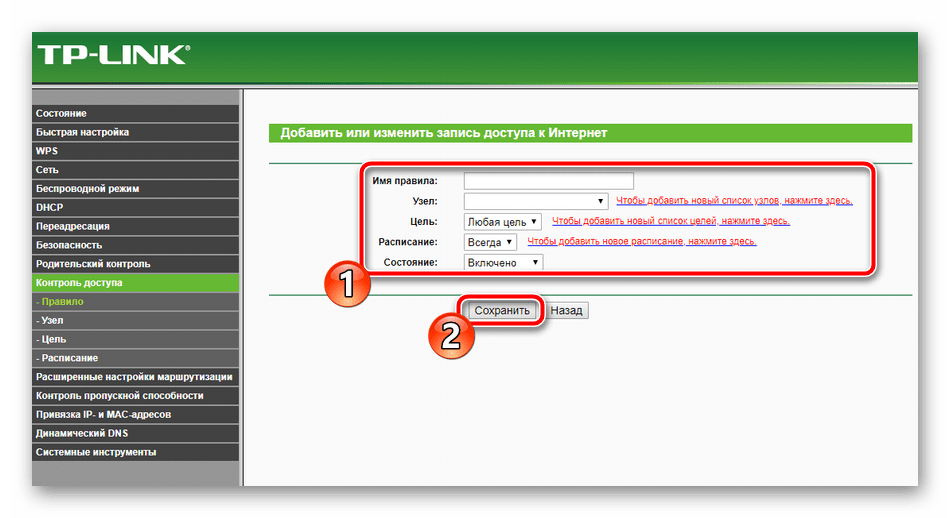
- Здесь вы выбираете узел из присутствующих в списке, задаете цель, расписание и состояние. Перед выходом нажмите на «Сохранить».
Завершение настройки
Остались только завершающие пункты, работа с которыми происходит буквально в несколько кликов:
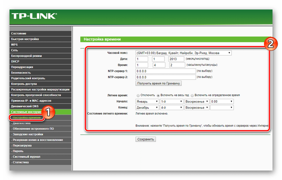
- В разделе «Системные инструменты» выберите «Настройка времени». В таблице задайте правильные значения даты и времени, чтобы обеспечить корректную работу расписания родительского контроля и параметров безопасности, а также правильную статистику по функционированию оборудования.
- В блоке «Пароль» вы можете изменить имя пользователя и установить новый ключ доступа. Данная информация применяется при входе в веб-интерфейс роутера.
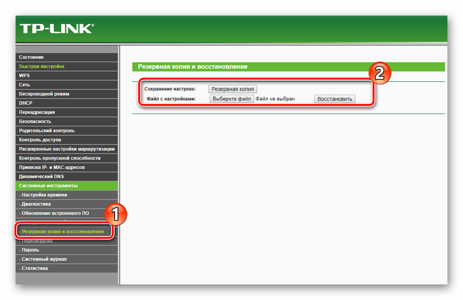
- В разделе «Резервная копия и восстановление» вам предлагают сохранить текущую конфигурацию в файл, чтобы в дальнейшем не возникло проблем с ее восстановлением.
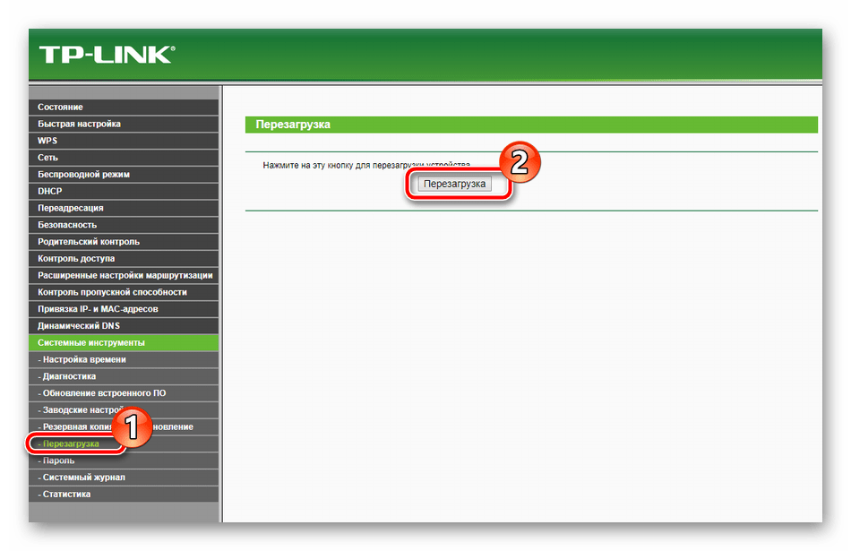
- В последнюю очередь кликните на кнопку «Перезагрузить» в подразделе с одноименным названием, чтобы после перезагрузки маршрутизатора все изменения вступили в силу.
На этом наша статья подходит к логическому завершению. Надеемся, сегодня вы узнали всю необходимую информацию о настройке роутера TP-Link TL-MR3420 и у вас не возникло трудностей при самостоятельном выполнении этой процедуры.

REV5.0.0 1910012177
User Guide
3G/4G Wireless N Router
TL-MR3420

Contents
About This Guide ……………………………………………………………………………………………1
Chapter 1. Get to Know About Your Router . . . . . . . . . . . . . . . . . . . . . . . . . . .2
1. 1. Product Overview. . . . . . . . . . . . . . . . . . . . . . . . . . . . . . . . . . . . . . . . . . . . . . . . . . . . . . . . . . . . 3
1. 2. Panel Layout. . . . . . . . . . . . . . . . . . . . . . . . . . . . . . . . . . . . . . . . . . . . . . . . . . . . . . . . . . . . . . . . . 3
1. 2. 1. Top View . . . . . . . . . . . . . . . . . . . . . . . . . . . . . . . . . . . . . . . . . . . . . . . . . . . . . . . . . . . . . . 3
1. 2. 2. The Side and Back Panel . . . . . . . . . . . . . . . . . . . . . . . . . . . . . . . . . . . . . . . . . . . . . . 5
Chapter 2. Connect the Hardware . . . . . . . . . . . . . . . . . . . . . . . . . . . . . . . . . . . .6
2. 1. Position Your Router . . . . . . . . . . . . . . . . . . . . . . . . . . . . . . . . . . . . . . . . . . . . . . . . . . . . . . . . . 7
2. 2. Connect Your Router. . . . . . . . . . . . . . . . . . . . . . . . . . . . . . . . . . . . . . . . . . . . . . . . . . . . . . . . . 7
2. 2. 1. Plug and Play via 3G/4G USB Modem . . . . . . . . . . . . . . . . . . . . . . . . . . . . . . . . . 7
2. 2. 2. Connect to DSL/Cable/Satellite Modem . . . . . . . . . . . . . . . . . . . . . . . . . . . . . . 8
Chapter 3. Set Up Internet Connection . . . . . . . . . . . . . . . . . . . . . . . . . . . . . 10
3. 1. Log In to the Router. . . . . . . . . . . . . . . . . . . . . . . . . . . . . . . . . . . . . . . . . . . . . . . . . . . . . . . . . 11
3. 2. Use Quick Setup Wizard . . . . . . . . . . . . . . . . . . . . . . . . . . . . . . . . . . . . . . . . . . . . . . . . . . . . 11
3. 3. Set Up IPv6 Tunnel. . . . . . . . . . . . . . . . . . . . . . . . . . . . . . . . . . . . . . . . . . . . . . . . . . . . . . . . . . 12
3. 3. 1. Use the Public IPv6 Tunnel Service-6to4. . . . . . . . . . . . . . . . . . . . . . . . . . . . . . 12
3. 3. 2. Specify the 6rd Tunnel with Parameters Provided by Your ISP . . . . . . . . . 13
Chapter 4. Guest Network. . . . . . . . . . . . . . . . . . . . . . . . . . . . . . . . . . . . . . . . . . 14
4. 1. Create a Network for Guests . . . . . . . . . . . . . . . . . . . . . . . . . . . . . . . . . . . . . . . . . . . . . . . 15
4. 2. Customize Guest Network Options. . . . . . . . . . . . . . . . . . . . . . . . . . . . . . . . . . . . . . . . . . 15
Chapter 5. Parental Controls . . . . . . . . . . . . . . . . . . . . . . . . . . . . . . . . . . . . . . . 17
Chapter 6. Bandwidth Control . . . . . . . . . . . . . . . . . . . . . . . . . . . . . . . . . . . . . . 21
6. 1. Set Upstream and Downstream Bandwidth. . . . . . . . . . . . . . . . . . . . . . . . . . . . . . . . . . 22
6. 2. Controlling Rules . . . . . . . . . . . . . . . . . . . . . . . . . . . . . . . . . . . . . . . . . . . . . . . . . . . . . . . . . . . 22
Chapter 7. USB Settings. . . . . . . . . . . . . . . . . . . . . . . . . . . . . . . . . . . . . . . . . . . . 24
7. 1. Access the USB Storage Device . . . . . . . . . . . . . . . . . . . . . . . . . . . . . . . . . . . . . . . . . . . . 25
7. 1. 1. Access the USB Device Locally. . . . . . . . . . . . . . . . . . . . . . . . . . . . . . . . . . . . . . . 25
7. 1. 2. Access the USB Device Remotely . . . . . . . . . . . . . . . . . . . . . . . . . . . . . . . . . . . . 26
7. 1. 3. Customize Access Settings . . . . . . . . . . . . . . . . . . . . . . . . . . . . . . . . . . . . . . . . . . 28

7. 2. Media Sharing . . . . . . . . . . . . . . . . . . . . . . . . . . . . . . . . . . . . . . . . . . . . . . . . . . . . . . . . . . . . . . 31
7. 3. Printer Sharing. . . . . . . . . . . . . . . . . . . . . . . . . . . . . . . . . . . . . . . . . . . . . . . . . . . . . . . . . . . . . . 32
Chapter 8. Network Security . . . . . . . . . . . . . . . . . . . . . . . . . . . . . . . . . . . . . . . 36
8. 1. Protect the Network from Cyber Attacks . . . . . . . . . . . . . . . . . . . . . . . . . . . . . . . . . . . . 37
8. 2. Service Filtering . . . . . . . . . . . . . . . . . . . . . . . . . . . . . . . . . . . . . . . . . . . . . . . . . . . . . . . . . . . . 38
8. 3. Access Control . . . . . . . . . . . . . . . . . . . . . . . . . . . . . . . . . . . . . . . . . . . . . . . . . . . . . . . . . . . . . 38
8. 4. IP & MAC Binding . . . . . . . . . . . . . . . . . . . . . . . . . . . . . . . . . . . . . . . . . . . . . . . . . . . . . . . . . . . 40
8. 5. Yandex DNS . . . . . . . . . . . . . . . . . . . . . . . . . . . . . . . . . . . . . . . . . . . . . . . . . . . . . . . . . . . . . . . . 41
Chapter 9. NAT Forwarding. . . . . . . . . . . . . . . . . . . . . . . . . . . . . . . . . . . . . . . . . 43
9. 1. Share Local Resources on the Internet by Virtual Servers. . . . . . . . . . . . . . . . . . . . 44
9. 2. Open Ports Dynamically by Port Triggering . . . . . . . . . . . . . . . . . . . . . . . . . . . . . . . . . . 45
9. 3. Make Applications Free from Port Restriction by DMZ . . . . . . . . . . . . . . . . . . . . . . . 46
9. 4. Make Xbox Online Games Run Smoothly by UPnP . . . . . . . . . . . . . . . . . . . . . . . . . . . 47
Chapter 10. VPN. . . . . . . . . . . . . . . . . . . . . . . . . . . . . . . . . . . . . . . . . . . . . . . . . . . . . 49
Chapter 11. Customize Your Network Settings. . . . . . . . . . . . . . . . . . . . . . . 52
11. 1. Change the LAN Settings . . . . . . . . . . . . . . . . . . . . . . . . . . . . . . . . . . . . . . . . . . . . . . . . . . . 53
11. 2. Specify DHCP Server Settings . . . . . . . . . . . . . . . . . . . . . . . . . . . . . . . . . . . . . . . . . . . . . . 53
11. 3. Set Up a Dynamic DNS Service Account . . . . . . . . . . . . . . . . . . . . . . . . . . . . . . . . . . . . 55
11. 4. Create Static Routes. . . . . . . . . . . . . . . . . . . . . . . . . . . . . . . . . . . . . . . . . . . . . . . . . . . . . . . . 55
11. 5. Specify Wireless Settings. . . . . . . . . . . . . . . . . . . . . . . . . . . . . . . . . . . . . . . . . . . . . . . . . . . 57
11. 6. Use WPS for Wireless Connection . . . . . . . . . . . . . . . . . . . . . . . . . . . . . . . . . . . . . . . . . . 58
11. 6. 1. Use the WPS Wizard for Wi-Fi Connections. . . . . . . . . . . . . . . . . . . . . . . . . . 58
11. 6. 2. Use the PIN for Wi-Fi connections . . . . . . . . . . . . . . . . . . . . . . . . . . . . . . . . . . . 59
11. 7. Schedule Your Wireless Function . . . . . . . . . . . . . . . . . . . . . . . . . . . . . . . . . . . . . . . . . . . 59
Chapter 12. Manage the Router . . . . . . . . . . . . . . . . . . . . . . . . . . . . . . . . . . . . . 61
12. 1. Set Up System Time . . . . . . . . . . . . . . . . . . . . . . . . . . . . . . . . . . . . . . . . . . . . . . . . . . . . . . . . 62
12. 2. Change Operation Mode. . . . . . . . . . . . . . . . . . . . . . . . . . . . . . . . . . . . . . . . . . . . . . . . . . . . 63
12. 3. Test the Network Connectivity . . . . . . . . . . . . . . . . . . . . . . . . . . . . . . . . . . . . . . . . . . . . . . 63
12. 4. Upgrade the Firmware . . . . . . . . . . . . . . . . . . . . . . . . . . . . . . . . . . . . . . . . . . . . . . . . . . . . . . 63
12. 4. 1. Online Upgrade . . . . . . . . . . . . . . . . . . . . . . . . . . . . . . . . . . . . . . . . . . . . . . . . . . . . . 64
12. 4. 2. Manual Upgrade . . . . . . . . . . . . . . . . . . . . . . . . . . . . . . . . . . . . . . . . . . . . . . . . . . . . 64
12. 5. Backup and Restore Configuration Settings . . . . . . . . . . . . . . . . . . . . . . . . . . . . . . . . . 65
12. 6. Auto Reboot . . . . . . . . . . . . . . . . . . . . . . . . . . . . . . . . . . . . . . . . . . . . . . . . . . . . . . . . . . . . . . . . 66
12. 7. Change the Login Password . . . . . . . . . . . . . . . . . . . . . . . . . . . . . . . . . . . . . . . . . . . . . . . . 66
12. 8. Local Management . . . . . . . . . . . . . . . . . . . . . . . . . . . . . . . . . . . . . . . . . . . . . . . . . . . . . . . . . 67

12. 9. Remote Management . . . . . . . . . . . . . . . . . . . . . . . . . . . . . . . . . . . . . . . . . . . . . . . . . . . . . . . 68
12. 10. System Log. . . . . . . . . . . . . . . . . . . . . . . . . . . . . . . . . . . . . . . . . . . . . . . . . . . . . . . . . . . . . . . . . 68
12. 11. Monitor the Internet Traffic Statistics. . . . . . . . . . . . . . . . . . . . . . . . . . . . . . . . . . . . . . . . 70
FAQ ………………………………………………………………………………………………………………..72
1
About This Guide
This guide is a complement of Quick Installation Guide. The Quick Installation Guide
instructs you on quick internet setup, and this guide provides details of each function
and shows you the way to configure these functions appropriate to your needs.
When using this guide, please notice that features of the router may vary slightly
depending on the model and software version you have, and on your location, language,
and internet service provider. All screenshots, images, parameters and descriptions
documented in this guide are used for demonstration only.
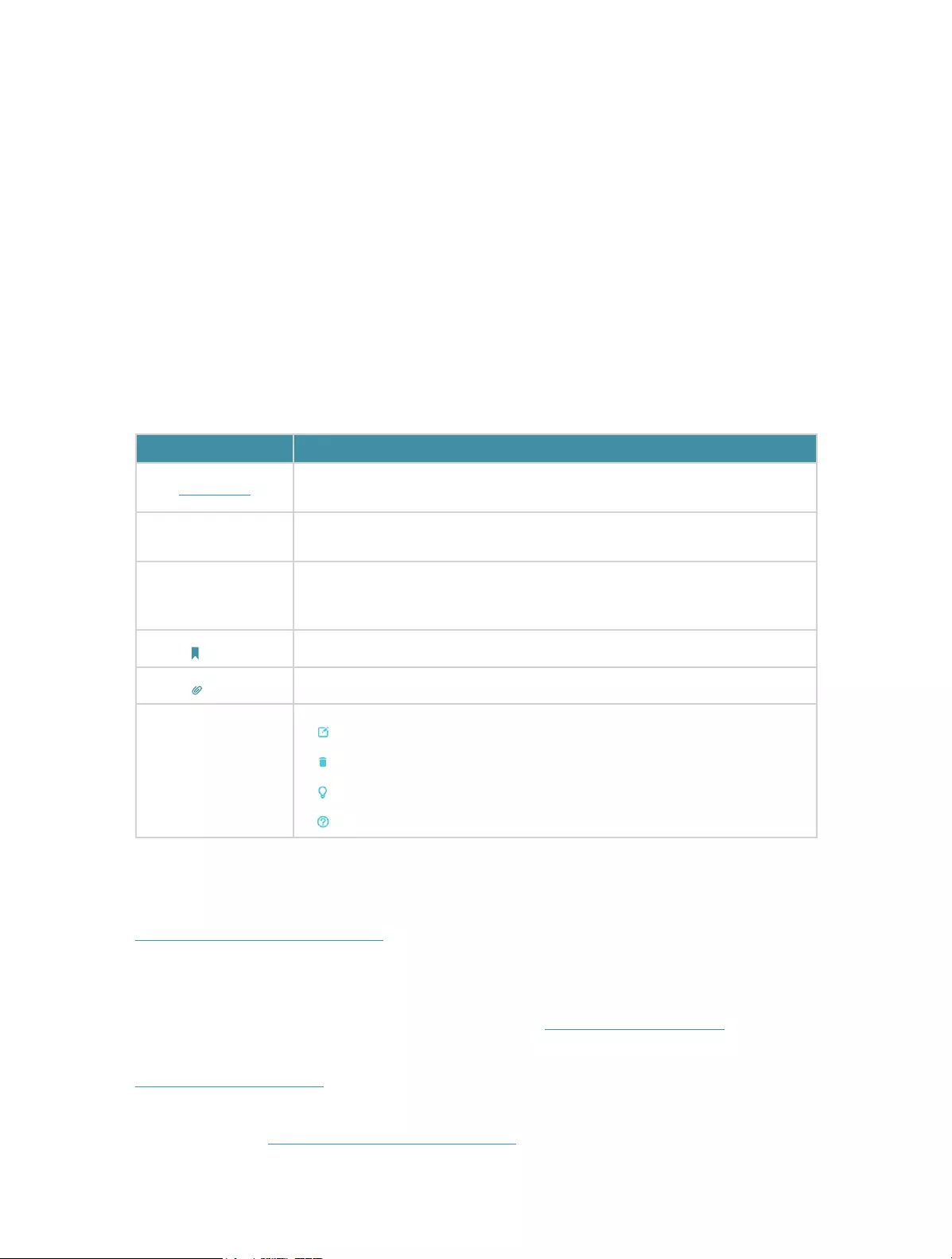
Conventions
In this guide the following conventions are used:
Convention Description
Underlined Underlined words or phrases are hyperlinks. You can click to redirect to a
website or a specific section.
Teal Contents to be emphasized and texts on the web page are in teal, including the
menus, items, buttons, etc.
>
The menu structures to show the path to load the corresponding page.
For example, Advanced > Wireless > MAC Filtering means the MAC Filtering
function page is under the Wireless menu that is located in the Advanced tab.
Note: Ignoring this type of note might result in a malfunction or damage to the device.
Tips: Indicates important information that helps you make better use of your device.
symbols on the web
page
• click to edit the corresponding entry.
• click to delete the corresponding entry.
• click to enable or disable the corresponding entry.
• click to view more information about items on the page.
More Info
The latest software, management app and utility can be found at Download Center at
http://www.tp-link.com/support.
The Quick Installation Guide can be found where you find this guide or inside the
package of the router.
Specifications can be found on the product page at http://www.tp-link.com.
A Technical Support Forum is provided for you to discuss our products at
http://forum.tp-link.com.
Our Technical Support contact information can be found at the Contact Technical
Support page at http://www.tp-link.com/support.

Chapter 1
Get to Know About Your
Router
This chapter introduces what the router can do and shows its appearance.
This chapter contains the following sections:
• Product Overview
• Panel Layout

3
Chapter 1 Get to Know About Your Router
1. 1. Product Overview
The TP-Link router is designed to fully meet the need of Small Office/Home Office
(SOHO) networks and the users demanding higher networking performance. The
powerful antennas ensure continuous Wi-Fi signal to all your devices while boosting
widespread coverage throughout your home, and the built-in Ethernet ports supply
high-speed connection to your wired devices.
Moreover, it is simple and convenient to set up and use the TP-Link router due to its
intuitive web interface.
1. 2. Panel Layout
1. 2. 1. Top View
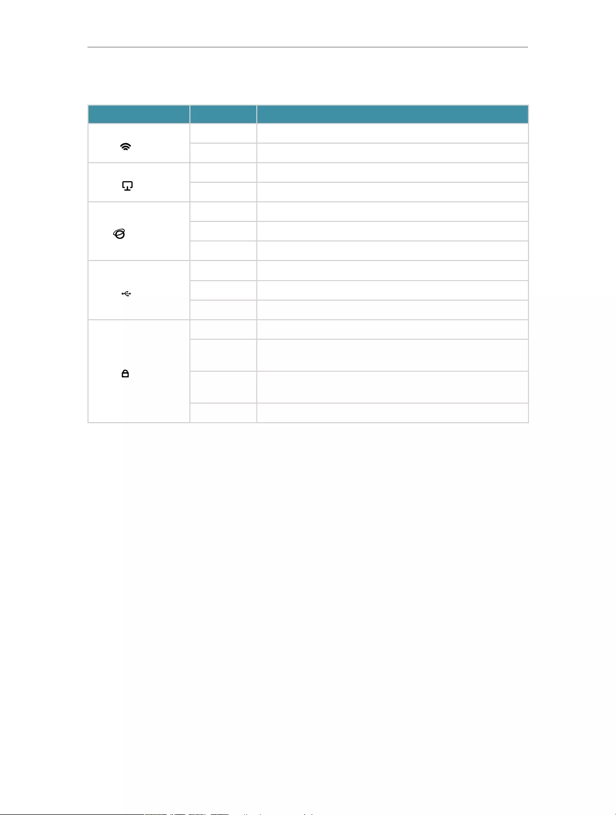
The router’s LEDs (view from left to right) are located on the top. You can check the
router’s working status by following the LED Explanation table.
LED Explanation
Name Status Indication
(Power)
On Power is on.
Off Power is off.
4
Chapter 1 Get to Know About Your Router
LED Explanation
Name Status Indication
(Wi-Fi)
On The wireless function is enabled.
Off The wireless function is disabled.
(LAN)
On At least one powered-on device is connected to a LAN port.
Off No powered-on device is connected to a LAN port.
(Internet)
Green The internet is available.
Off The WAN port is not connected.
Red The WAN port is connected, but the internet is not available.
(USB)
On The inserted USB device is ready to use.
Flashing The USB device is being detected.
Off No device is plugged into the USB port.
(WPS)
On A device is connected to the router successfully using WPS.
Quick
Flashing A device fails to connect to the router using WPS.
Slow
Flashing
A device is being connecting to the router using WPS. This
process takes up to 2 minutes.
Off No WPS connection is established.

5
Chapter 1 Get to Know About Your Router
1. 2. 2. The Side and Back Panel
The following parts (view from left to right) are located on the rear and side panel.
Item Description
Power Port For connecting the router to a power socket via the provided power adapter.
Power On/Off Button Press this button to power on/off the router.
WAN Port For connecting to a DSL/Cable modem, or an Ethernet jerk.
Ethernet Ports (1-4) For connecting the router to your PC or other Ethernet network devices.
WIFI Button Press this button to turn on/off the Wi-Fi of the router.
WPS/RESET Button
Press this button, and immediately press the WPS button on your device to
establish WPS connection.
Press this button for about 5 seconds to factory reset the router.
USB Port For connecting to a 3G/4G modem or a USB disk.
Antennas Upright the antennas for best Wi-Fi performance.

Chapter 2
Connect the Hardware
This chapter contains the following sections:
• Position Your Router
• Connect Your Router
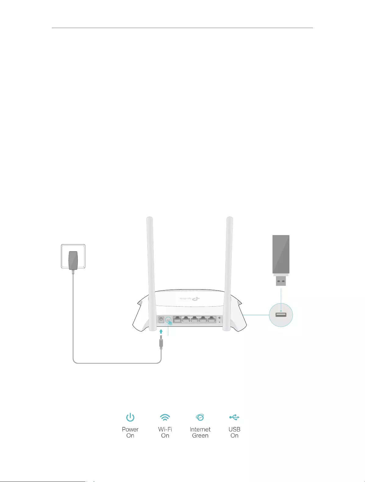
7
Chapter 2 Connect the Hardware
2. 1. Position Your Router
• The product should not be located where it will be exposed to moisture or excessive
heat.
• Place the router in a location where it can be connected to multiple devices as well as
to a power source.
• Make sure the cables and power cord are safely placed out of the way so they do not
create a tripping hazard.
• The router can be placed on a shelf or desktop.
• Keep the router away from devices with strong electromagnetic interference, such as
Bluetooth devices, cordless phones and microwaves.
2. 2. Connect Your Router
2. 2. 1. Plug and Play via 3G/4G USB Modem
Power
Adapter
Router
3G/4G USB Modem
2
POWER ON/OFF WAN 1 2 3 4 WPS/
RESET
WIFI
1
1 ) Press to turn on the router.
2 ) Plug in a 3G/4G USB modem with a SIM/UIM card.
3 ) Wait about 2 minutes and then confirm that the following LEDs are on and solid.
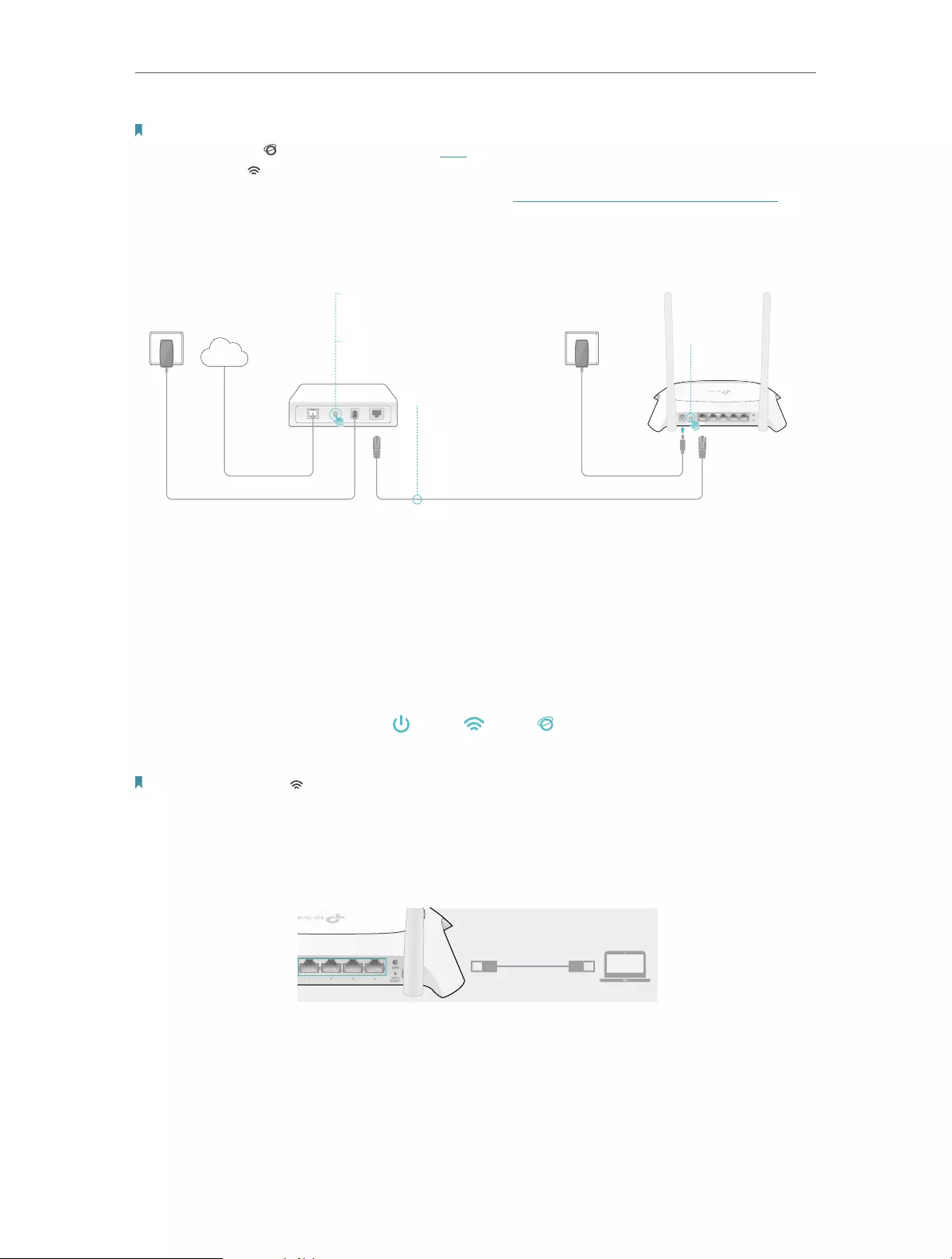
8
Chapter 2 Connect the Hardware
Note:
• If the Internet LED ( ) is off or red, please refer to FAQ.
• If the Wi-Fi LED ( ) is off, press the Wi-Fi button on the rear panel and then check the LED again.
• You can find the latest modem compatibility list in our website: http://www.tp-link.com/en/comp-list.html.
2. 2. 2. Connect to DSL/Cable/Satellite Modem
1
Rout
Power
r
POWER ON/OFF WAN1 234WPS/
RESET
WIFI
Power
Adapter
Modem
Internet
3
2
4
1 ) Power off the modem and remove the backup battery if it has one.
2 ) Connect the modem to the router’s WAN port via an Ethernet cable.
3 ) Turn on the modem and then wait about 2 minutes for it to restart.
4 ) Press to turn on the router.
5 ) Confirm that the following LEDs are on and solid to verify the hardware
connection is correct.
Power
Wi-Fi
Note: If the Wi-Fi LED ( ) is off, press the WIFI button on the rear panel and then check the LED again.
1. Connect your computer to the router.
• Method 1: Wired
Turn off the Wi-Fi on your computer and connect the devices as shown below.
Wired
• Method 2: Wirelessly
1 ) Find the SSID (Network Name) and Wireless Password printed on the label at
the bottom of the router.
2 ) Click the network icon of your computer or go to the Wi-Fi settings of your
smart device, and then select the SSID to join the network.
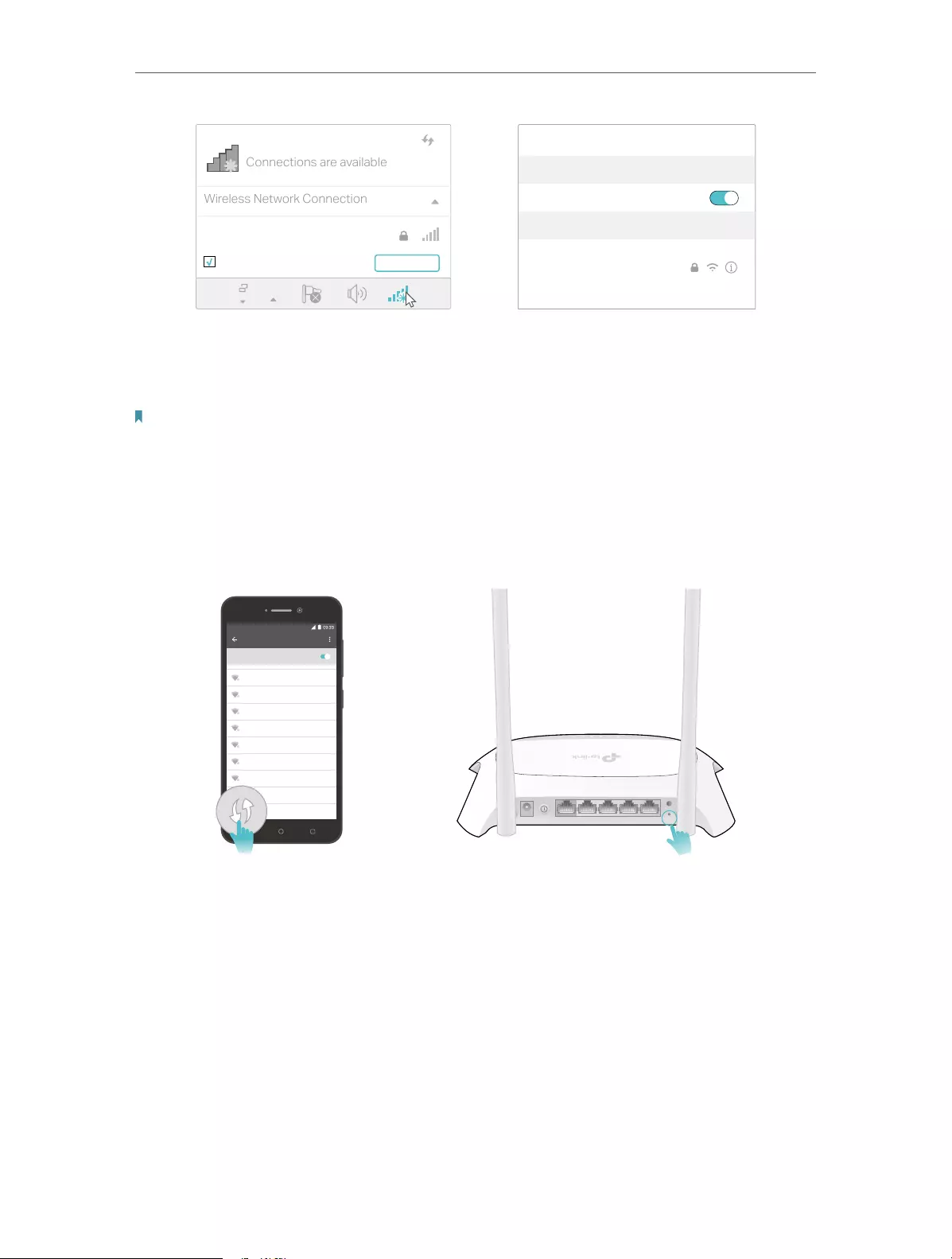
9
Chapter 2 Connect the Hardware
Connections are available
Wireless Network Connection
Connect automatically Connect
TP-Link_XXXX
Wi-Fi
Wi-Fi
TP-Link_XXXX
CHOOSE A NETWORK…
Other…
< Settings
• Method 3: Use the WPS button
Wireless devices that support WPS, including Android phones, tablets, most USB
network cards, can be connected to your router through this method.
Note:
• WPS is not supported by iOS devices.
• The WPS function cannot be configured if the wireless function of the router is disabled. Also, the WPS
function will be disabled if your wireless encryption is WEP. Please make sure the wireless function is
enabled and is configured with the appropriate encryption before configuring the WPS.
1. Tap the WPS icon on the device’s screen. Here we take an Android phone for instance.
2. Within two minutes, press the WPS button on your router.
Close to
WLAN
On
TP-Link_2017
TP-Link_Home
My Home
My Network
Home Network
TP-Link_Network
TP-Link_Test
4G
POWER ON/OFF WAN 1 2 3 4 WPS/
RESET
WIFI

Chapter 3
Set Up Internet Connection
This chapter introduces how to connect your router to the internet. The router is
equipped with a web-based Quick Setup wizard. It has many ISP information built in,
automates many of the steps and verifies that those steps have been successfully
completed.
It contains the following sections:
• Log In to the Router
• Use Quick Setup Wizard
• Set Up IPv6 Tunnel

11
Chapter 3 Set Up Internet Connection
3. 1. Log In to the Router
The Quick Setup Wizard will guide you through the process to set up your router to
access the internet.
1. Set up the TCP/IP Protocol in Obtain an IP address automatically mode on your
computer.
2. Visit http://tplinkwifi.net, and create a password for future logins.
3. Follow the step-by-step instructions to set up your router to access the internet.
Note: If the login window does not appear, please refer to the FAQ section.
3. 2. Use Quick Setup Wizard
The Quick Setup Wizard will walk you through the process to set up your router.
1. Visit http://tplinkwifi.net, and log in with the password you set for the router.
2. Go to Quick Setup, select your Time zone and click Next to continue.
3. Select the Operation Mode as needed and click Next. Then follow the screen
instructions to complete the configuration.
Note: The router can be configured with a primary WAN/3G/4G connection and a 3G/4G USB modem/WAN connection
as a backup solution to ensure “always on“ internet. In this case, select 3G/4G Router Mode with Ewan Backup or Wireless
Router Mode with 3G/4G Backup.

12
Chapter 3 Set Up Internet Connection
3. 3. Set Up IPv6 Tunnel
The IPv6 Tunnel feature helps you obtain IPv6 resources based on an IPv4 WAN
connection or vice versa.
IPv6 Tunnel is a transition mechanism that allows isolated IPv6 hosts and networks to
reach each other over IPv4-only infrastructure before IPv6 completely supplants IPv4.
It is a temporary solution for networks that do not support native dual-stack, where
both IPv6 and IPv4 run independently.
The router provides three tunneling mechanisms: 6to4, 6rd and DS-Lite. The way to set
up 6rd and DS-Lite tunnel are similar.
3. 3. 1. Use the Public IPv6 Tunnel Service-6to4
The 6to4 tunnel is a kind of public service. If there are any 6to4 servers on your network,
you can use this mechanism to access IPv6 service. If your ISP provides you with an
IPv4-only connection but you want to visit IPv6 websites, you can try to set up a 6to4
tunnel.
Set up the IPv6 tunnel though my ISP doesn’t provide me with
the tunnel service.
1. Visit http://tplinkwifi.net, and log in with the password you
set for the router.
2. Go to Advanced > Network > IPv6 Tunnel.
3. Tick the check box, select 6to4 as the tunneling mechanism
and select a WAN connection from the drop-down list, then
click Save.
Note: If there is no available WAN connection to choose, make sure you have
connected to the internet.
Now you can visit the IPv6 websites with the 6to4 tunnel.
Note: Still not being able to access IPv6 resources means that not any 6to4 public server was found in your network.
You can contact your ISP to sign up for IPv6 connection service.
I want to:
How can I
do that?
Done!

13
Chapter 3 Set Up Internet Connection
3. 3. 2. Specify the 6rd Tunnel with Parameters Provided by Your ISP
Specify the 6rd tunnel with the parameters provided by my 6rd
tunnel service provider.
1. Visit http://tplinkwifi.net, and log in with the passwod you set
for the router.
2. Go to Advanced > Network > IPv6 Tunnel.
3. Tick the check box, select 6rd as the tunneling mechanism
and select a WAN connection from the drop-down list.
4. According to the parameters provided by your ISP, choose
Auto or Manual. More parameters are needed if you choose
Manual.
5. Click Save.
Note:
If there is no available WAN connection to choose, make sure you have
connected to the internet and the connection type is not Bridge.
Now you can visit the IPv6 websites with the 6rd tunnel.
Tips: The way to set up DS-Lite tunnel is similar to that of 6rd tunnel. If you are provided with an IPv6-only WAN
connection and have signed up for DS-Lite tunnel service, specify the DS-Lite tunnel by referring to the steps above.
I want to:
How can I
do that?
How can I
do that?
Done!

Chapter 4
Guest Network
This function allows you to provide Wi-Fi access for guests without disclosing your
main network. When you have guests in your house, apartment, or workplace, you can
create a guest network for them. In addition, you can customize guest network options
to ensure network security and privacy.
It contains the following sections:
• Create a Network for Guests
• Customize Guest Network Options

15
Chapter 4 Guest Network
4. 1. Create a Network for Guests
1. Visit http://tplinkwifi.net, and log in with the password you set for the router.
2. Go to Advanced > Guest Network. Locate the Wireless section.
3. Create a guest network as needed.
1 ) Tick the Enable Guest Network checkbox.
2 ) Customize the SSID. Don‘t select Hide SSID unless you want your guests to
manually input the SSID for guest network access.
3 ) Set Security to WPA/WPA2 Personal, keep the default Version and Encryption
values, and customize your own password.
4. Click Save. Now your guests can access your guest network using the SSID and
password you set!
Tips: To view guest network information, go to Advanced > Status and locate the Guest Network section.
4. 2. Customize Guest Network Options
1. Visit http://tplinkwifi.net, and log in with the password you set for the router.
2. Go to Advanced > Guest Network. Locate the Settings section.
3. Customize guest network options as needed.

16
Chapter 4 Guest Network
• Allow Guests to Access Each Other
Tick this checkbox if you want to allow the wireless clients on your guest network
to communicate with each other via methods such as network neighbors and Ping.
• Allow Guests to Access My Local Network
Tick this checkbox if you want to allow the wireless clients on your guest network
to communicate with the devices connected to your router’s LAN ports or main
network via methods such as network neighbors and Ping.
• Allow Guests to Access My USB Storage Sharing
Tick this checkbox if you want to allow the wireless clients on your guest network to
access your files on the USB disk connected to your router.
• Enable guest network bandwidth control
Tick this checkbox if you want to apply the Bandwidth Control settings to the
wireless devices on your guest network .
4. Click Save. Now you can ensure network security and privacy!
Tips: To view guest network information, go to Advanced > Status and locate the Guest Network section.

Chapter 5
Parental Controls
This function allows you to block inappropriate, explicit and malicious websites, and
control access to specified websites at specified time.

18
Chapter 5 Parental Controls
Control the times of day my children or other home network
users are allowed to access the internet and even types of
websites they can visit.
For example, I want to allow my children’s devices (e.g. a computer
or a tablet) to access only www.tp-link.com and Wikipedia.org
from 18:00 (6PM) to 22:00 (10PM) at the weekend and not other
times.
1. Visit http://tplinkwifi.net, and log in with the password you
set for the router.
2. Go to Advanced > Parental Controls and enable Parental
Controls.
3. Click Add. And then Click Scan, and select the access device.
Or input the Device Name and MAC Address manually.
4. Click the icon to set the internet Access Time. Drag the
cursor over the appropriate cell(s) and click OK.
I want to:I want
How can I
do that?

19
Chapter 5 Parental Controls
5. Enter a Description for the entry, tick the Enable This Entry
checkbox, and then click OK.
6. Select Whitelist as the restriction policy.
Tips:
• With Blacklist selected, the controlled devices cannot access any websites
containing the specified keywords during the Internet Access Time period.
• With Whitelist selected, the controlled devices can only access websites containing
the specified keywords during the Internet Access Time period.
7. Click . Enter a website and click Save.
You can add up to 32 keywords for either Blacklist or Whitelist.
Below are some sample entries to allow access.
• For Whitelist: Enter a web address (e.g. wikipedia.org) to allow access
only to its related websites. If you wish to block all internet browsing
access, do not add any keyword to the Whitelist.
• For Blacklist: Specify a web address (e.g. wikipedia.org), a web address
keyword (e.g. wikipedia) or a domain suffix (eg. .edu or .org) to block
access only to the websites containing that keyword or suffix.

20
Chapter 5 Parental Controls
Now you can control your children’s internet access as needed.
Done!

Chapter 6
Bandwidth Control
This chapter introduces how to set bandwidth limits minimize the impact caused when
the connection is under heavy load.
It contains the following sections:
• Set Upstream and Downstream Bandwidth
• Controlling Rules

22
Chapter 6 Bandwidth Control
6. 1. Set Upstream and Downstream Bandwidth
1. Visit http://tplinkwifi.net, and log in with the password you set for the router.
2. Go to Advanced > Bandwidth Control.
3. Enable Bandwidth Control and enter the Total Upstream Bandwidth and Total
Downstream Bandwidth.
4. Click Save.
6. 2. Controlling Rules
1. Visit http://tplinkwifi.net, and log in with the password you set for the router.
2. Go to Advanced > Bandwidth Control.
3. Click Add and fill in the blanks.

23
Chapter 6 Bandwidth Control
• IP Range: Enter the IP range of your devices that you want to apply Bandwidth
Control to.
• Port Range: Enter the Port range of the protocols.
• Protocal: Select the protocols of services that you want to control.
• Priority: Select priority from 1 to 5. 1 means the highest priority.
• Upstream/Downstream: Enter the minimun and maxmium upstream/
downstream bandwidth you want to allocate.
4. Click Save.

Chapter 7
USB Settings
This chapter describes how to use the USB ports to share files, media and a printer
from the USB storage devices over your home network locally, or remotely through the
internet.
The router supports USB external flash drives, hard drives and USB printers.
It contains the following sections:
• Access the USB Storage Device
• Media Sharing
• Printer Sharing

25
Chapter 7 USB Settings
7. 1. Access the USB Storage Device
Insert your USB storage device into the router’s USB port and then access files stored
there locally or remotely.
Tips:
• If you use USB hubs, make sure no more than 4 devices are connected to the router.
• If the USB storage device requires using bundled external power, make sure the external power has been connected.
• If you use a USB hard drive, make sure its file system is FAT32 or NTFS.
• Before you physically disconnect a USB device from the router, safely remove it to avoid data damage: Go to Advanced
> USB Settings > Device Settings and click .
7. 1. 1. Access the USB Device Locally
Insert your USB storage device into the router’s USB port and then refer to the following
table to access files stored on your USB storage device.
Windows
computer
¾Method 1:
Go to Computer > Network, then click the Network Server Name
(TL-MR3420 by default) in the Computer section.
Note:
Operations in different systems are similar. Here we take Windows 8 as an example.

26
Chapter 7 USB Settings
Windows
computer
¾Method 2:
Open the Windows Explorer (or go to Computer) and type the server
address \\tplinkwifi.net or ftp://tplinkwifi.net in the address bar, then
press Enter.
Mac
1 ) Select Go > Connect to Server.
2 ) Type the server address smb://tplinkwifi.net.
3 ) Click Connect.
4 ) When prompted, select the Guest radio box. (If you have set up a
username and a password to deny anonymous access to the USB
disks, you should select the Registered User radio box. To learn how
to set up an account for the access, refer to To set up authentication
for data security:.)
Tablet Use a third-party app for network files management.
Tips: You can also access your USB disk by using your Network/Media Server Name as the server address. Refer to
To customize the address of the USB disk: to learn more.
7. 1. 2. Access the USB Device Remotely
You can access your USB disk outside the local area network. For example, you can:

27
Chapter 7 USB Settings
• Share photos and other large files with your friends without logging in to (and paying
for) a photo-sharing site or email system.
• Get a safe backup for the materials for a presentation.
• Remove the files on your camera’s memory card from time to time during the journey.
Note: If your ISP assigns a private WAN IP address (such as 192.168.x.x or 10.x.x.x), you cannot use this feature
because private addresses are not routed on the Internet.
Follow the steps below to configure remote access settings.
1. Visit http://tplinkwifi.net, and log in with the password you set for the router.
2. Go to Advanced > USB Sharing > USB Storage Device.
3. Tick the FTP(via Internet) checkbox, and then click Save.
4. Refer to the following table to access your USB disk remotely.

28
Chapter 7 USB Settings
Computer
1 ) Open the Windows Explorer (or go to Computer, only for Windows
users) or open a web browser.
2 ) Type the server address in the address bar:
Type in ftp://<WAN IP address of the router>:<port number> (such
as ftp://59.40.2.243:21). If you have specified the domain name
of the router, you can also type in ftp://<domain name>:<port
number> (such as ftp://MyDomainName:21)
3 ) Press Enter on the keyboard.
4 ) Access with the username and password you set in To set up
authentication for data security:.
Tips:
You can also access the USB disk via a third-party app for network files management, which can
resume broken file transfers.
Tablet Use a third-party app for network files management.
Tips: Click Set Up a Dynamic DNS Service Account to learn how to set up a domain name for you router.
7. 1. 3. Customize Access Settings
By default, all the network clients can access all folders on your USB disk. You can
customize your sharing settings by setting a sharing account, sharing specific contents
and setting a new sharing address on the router’s web management page.
1. Visit http://tplinkwifi.net, and log in with the password you set for the router.
2. Go to Advanced > USB Sharing > USB Storage Device.
¾To customize the address of the USB disk:
You can customize the server name and use the name to access your USB disk.
1. On the Sharing Settings part, make sure Network Neighborhood is ticked, and enter
a Network/Media Server Name as you like, such as MyShare, then click Save.

29
Chapter 7 USB Settings
2. Now you can access the USB disk by visiting \\MyShare (for Windows) or
smb://MyShare (for Mac).
¾To only share specific content:
1. Focus on the Folder Sharing section. Click the button to disable Share All, then click
Add to add a new sharing folder.
2. Select the Volume Name and Folder Path, then enter a Folder Name as you like.
3. Decide the way you share the folder:

30
Chapter 7 USB Settings
• Enable Authentication: Tick to enable authentication for this folder sharing, and
you will be required to log in to the Sharing Account to access the USB disk.
Refer to To set up authentication for data security: to learn more.
• Enable Write Access: If you tick this checkbox, network clients can modify this
folder.
• Enable Media Sharing: Tick to enable media sharing for this folder, and you can
view photos, play music and watch movies stored on the USB disk directly from
DLNA-supported devices. Click Media Sharing to learn more.
4. Click OK.
Tips: The router can share 32 volumes at most. You can click on the page to detach the corresponding volume you
do not need to share.
¾To set up authentication for data security:
You can set up authentication for your USB device so that network clients will be
required to enter username and password when accessing the USB disk.
1. On the Sharing Account part, Choose Use Default Account or Use New Account.
The username and password are both admin for default account. If your choose
Use New Account, you have to customize the username and a password.
Note:
For Windows users, do not set the sharing username the same as the Windows username. Otherwise, Windows
credential mechanism may cause the following problems:
• If the sharing password is also the same as the Windows password, authentication will not work since the Windows
will automatically use its account information for USB access.
• If the sharing password is different from the Windows password, the Windows will be unable to remember your
credentials and you will always be required to enter the sharing password for USB access.

31
Chapter 7 USB Settings
2. Enable Authentication to apply the account you just set.
• If you leave Share All enabled, click the button to enable Authentication for all
folders.
• If Share All is disabled, enable Authentication for specific folders.
Note: Due to Windows credential mechanism, you might be unable to access the USB disk after changing Authentication
settings. Please log out from the Windows and try to access again. Or you can change the address of the USB disk by
referring to To customize the address of the USB disk:.
7. 2. Media Sharing
The feature of Media Sharing allows you to view photos, play music and watch movies
stored on the USB disk directly from DLNA-supported devices, such as your computer,
tablet and PS2/3/4.
1. When your USB disk is inseted into the router, your DLNA-supported devices (such
as your computer and pad) connected to the router can detect and play the media
files on the USB disks.
2. Refer to the following table for detailed instructions.

32
Chapter 7 USB Settings
Windows
Computer
• Go to Computer > Network, then click the Media Server Name (TL-MR3420
by default) in the Media Devices section.
Note:
Here we take Windows 8 as an example.
Tablet • Use a third-party DLNA-supported player.
7. 3. Printer Sharing
The feature of Printer Sharing helps you share a printer with different computers
connected to the router.
Note: Printers unlisted on this page may be incompatible with the router:
http://www.tp-link.com/common/compatible/print-server/.
1. Install the Driver of the Printer
Make sure you have installed the driver of the printer on each computer that needs
printer service.
If you do not have the driver, contact the printer manufacturer.
2. Connect the Printer
Cable a printer to the USB port with the USB cable. Wait several seconds until the
USB LED becomes solid on.
3. Install the TP-Link USB Printer Controller Utility
TP-Link USB Printer Controller Utility helps you access the shared printer. Download
and Install the utility on each computer that needs printer service.
1 ) Visit http://www.tp-link.com/app/usb/.
2 ) Click PC Utility (for Windows users) or Mac Utility to download the installation
file and uncompress it.

33
Chapter 7 USB Settings
3 ) Open the uncompressed folder, then click TP-Link USB Printer Controller Setup
(for Windows users) or TP-Link UDS Printer Controller Installer (for Mac users)
to install the utility.
4. Access the Printer
You should set the shared printer as Auto-Connect Printer on every computer that
needs printer service.
1 ) Double-click the icon on your desktop to launch the USB Printer Controller.
2 ) Highlight the printer you share.
Windows
Mac
3 ) Click the Auto-Connect for printing tab to pull down a list, then select Set Auto-
Connect Printer.
Windows

34
Chapter 7 USB Settings
Mac
4 ) Select the printer you share, then click Apply.
Windows
Mac

35
Chapter 7 USB Settings
5 ) You will see the printer marked as Auto-Connect Printer. Now you can print with
this printer.
Windows
Mac
Tips:
The Print Server also allows different clients to share the scan feature of MFPs (Multi-Function Printers). To scan
with TP-Link USB Printer Controller, right-click the printer and select Network Scanner. Then, a scanning window
will pop up. Finish the scanning process by following on-screen instructions.

Chapter 8
Network Security
This chapter guides you on how to protect your home network from cyber attacks
and unauthorized users by implementing these three network security functions. You
can protect your home network against DoS (Denial of Service) attacks from flooding
your network with server requests using DoS Protection, block or allow specific client
devices to access your network using Access Control, or you can prevent ARP spoofing
and ARP attacks using IP & MAC Binding.
It contains the following sections:
• Protect the Network from Cyber Attacks
• Service Filtering
• Access Control
• IP & MAC Binding
• Yandex DNS

37
Chapter 8 Network Security
8. 1. Protect the Network from Cyber Attacks
The SPI (Stateful Packet Inspection) Firewall and DoS (Denial of Service) Protection
protect the router from cyber attacks.
The SPI Firewall can prevent cyber attacks and validate the traffic that is passing
through the router based on the protocol. This function is enabled by default, and it’s
recommended to keep the default settings.
DoS Protection can protect your home network against DoS attacks from flooding your
network with server requests. Follow the steps below to configure DoS Protection.
1. Visit http://tplinkwifi.net, and log in with the password you set for the router.
2. Go to Advanced > Security > Firewall & DoS Protection.
3. Enable DoS Protection.
4. Set the level (Low, Middle or High) of protection for ICMP-FLOOD Attack Filtering,
UDP-FlOOD Attack Filtering and TCP-SYN-FLOOD Attack Filtering.
• ICMP-FLOOD Attack Filtering — Enable to prevent the ICMP (Internet Control
Message Protocol) flood attack.
• UDP-FlOOD Attack Filtering — Enable to prevent the UDP (User Datagram
Protocol) flood attack.
• TCP-SYN-FLOOD Attack Filtering — Enable to prevent the TCP-SYN (Transmission
Control Protocol-Synchronize) flood attack.
Tips: The level of protection is based on the number of traffic packets. The protection will be triggered
immediately when the number of packets exceeds the preset threshold value (the value can be set on DoS
Protection Level Settings), and the vicious host will be displayed in the Blocked DoS Host List.
5. Click Save.

38
Chapter 8 Network Security
8. 2. Service Filtering
Service Filtering is used to prevent certain users from accessing a specific service. It
can even block a user from accessing the internet.
1. Visit http://tplinkwifi.net, and log in with the password you set for the router.
2. Go to Advanced > Security > Service Filtering.
3. Enable Service Filtering.
4. Click Add.
5. Select a service type from the drop-down list and the corresponding parameters will
be automatically filled in. Select Custom if your desired service type is not listed and
enter the corresponding parameters.
6. Specify the IP address(es) this filtering rule will be applied to.
7. Click Save.
8. 3. Access Control
Access Control is used to block or allow specific client devices to access your network
(via wired or wireless) based on a list of blocked devices (Blacklist) or a list of allowed
devices (Whitelist).

39
Chapter 8 Network Security
Block or allow specific client devices to access my network (via
wired or wireless).
1. Visit http://tplinkwifi.net, and log in with the password you
set for the router.
2. Go to Advanced > Security > Access Control.
3. Enable Access Control.
4. Select the access mode to either block (recommended) or
allow the device(s) in the list.
To block specific device(s):
1 ) Select Blacklist and click Save.
2 ) Select the device(s) to be blocked in the Online Devices
table by ticking the checkbox(es).
3 ) Click Block above the Online Devices table. The selected
devices will be added to Devices in Blacklist automatically.
To allow specific device(s):
1 ) Select Whitelist and click Save.
2 ) Click Add in the Devices in Whitelist section. Enter the
Device Name and MAC Address (You can copy and paste
I want to:
How can I
do that?

40
Chapter 8 Network Security
the information from the Online Devices list if the device
is connected to your network).
3 ) Click OK.
Now you can block or allow specific client devices to access your
network (via wired or wireless) using the Blacklist or Whitelist.
8. 4. IP & MAC Binding
IP & MAC Binding, namely, ARP (Address Resolution Protocol) Binding, is used to bind
network device’s IP address to its MAC address. This will prevent ARP Spoofing and
other ARP attacks by denying network access to a device with matching IP address in
the Binding list, but unrecognized MAC address.
Prevent ARP spoofing and ARP attacks.
1. Visit http://tplinkwifi.net, and log in with the password you
set for the router.
2. Go to Advanced > Security > IP & MAC Binding.
3. Enable IP & MAC Binding.
4. Bind your device(s) according to your need.
To bind the connected device(s):
Click to add the corresponding device to the Binding List.
To bind the unconnected device:
1 ) Click Add in the Binding List section.
Done!
I want to:
How can I
do that?

41
Chapter 8 Network Security
2 ) Enter the MAC address and IP address that you want to
bind.
3 ) Tick the Enable This Entry checkbox and click Save.
Now you don’t need to worry about ARP spoofing and ARP
attacks!
8. 5. Yandex DNS
Yandex DNS filter will secure your devices from malicious websites and will restrict
adult websites for your children devices. You can configure a general filtering rule for all
devices or a separate one for certain devices.
1. Visit http://tplinkwifi.net, and log in with the password you set for the router.
2. Go to Advanced > Security > Yandex DNS.
3. Enable Yandex DNS. Select Disable, Basic, Safe or Child for the Enable Yandex DNS
for all devices.
Note: If Disable is selected, set Yandex DNS rules for certain devices.
4. Click Save.
¾To set a Yandex DNS rule for a certain device:
1. Click Add.
Done!

42
Chapter 8 Network Security
2. Click Scan to find a connected device you want to apply this rule to. You can also
maunally enter the MAC address of the device if it’s currently disconnected from the
router.
3. Select a Control Mode and enter a description for this rule.
4. Click Save.

Chapter 9
NAT Forwarding
The router’s NAT (Network Address Translation) feature makes devices on the LAN use
the same public IP address to communicate with devices on the internet, which protects
the local network by hiding IP addresses of the devices. However, it also brings about
the problem that an external host cannot initiatively communicate with a specified
device on the local network.
With the forwarding feature the router can penetrate the isolation of NAT and allows
devices on the internet to initiatively communicate with devices on the local network,
thus realizing some special functions.
The TP-Link router supports four forwarding rules. If two or more rules are set, the
priority of implementation from high to low is Virtual Servers, Port Triggering, UPNP and
DMZ.
It contains the following sections:
• Share Local Resources on the Internet by Virtual Servers
• Open Ports Dynamically by Port Triggering
• Make Applications Free from Port Restriction by DMZ
• Make Xbox Online Games Run Smoothly by UPnP

44
Chapter 9 NAT Forwarding
9. 1. Share Local Resources on the Internet by Virtual
Servers
When you build up a server on the local network and want to share it on the internet,
Virtual Servers can realize the service and provide it to internet users. At the same time
Virtual Servers can keep the local network safe as other services are still invisible from
the internet.
Virtual Servers can be used for setting up public services on your local network, such as
HTTP, FTP, DNS, POP3/SMTP and Telnet. Different services use different service ports.
Port 80 is used in HTTP service, port 21 in FTP service, port 25 in SMTP service and port
110 in POP3 service. Please verify the service port number before the configuration.
Share my personal website I’ve built in local network with my
friends through the internet.
For example, the personal website has been built on my home
PC (192.168.0.100). I hope that my friends on the internet can
visit my website in some way. The PC is connected to the router
with the WAN IP address 218.18.232.154.
Personal Website
Home
Router
WAN: 218.18.232.154LAN
1. Assign a static IP address to your PC, for example
192.168.1.100.
2. Visit http://tplinkwifi.net, and log in with the password you
set for the router.
3. Go to Advanced > NAT Forwarding > Virtual Servers.
4. Click Add. Click View Existing Services and select HTTP. The
External Port, Internal Port and Protocol will be automatically
filled in. Enter the PC’s IP address 192.168.1.100 in the
Internal IP field.
5. Click OK.
I want to:
How can I
do that?
INTERNET

45
Chapter 9 NAT Forwarding
Tips:
• It is recommended to keep the default settings of Internal Port and Protocol if you are
not clear about which port and protocol to use.
• If the service you want to use is not in the Service Type, you can enter the
corresponding parameters manually. You should verify the port number that the
service needs.
• You can add multiple virtual server rules if you want to provide several services in a
router. Please note that the External Port should not be overlapped.
Users on the internet can enter http:// WAN IP (in this example:
http:// 218.18.232.154) to visit your personal website.
Tips:
• The WAN IP should be a public IP address. For the WAN IP is assigned dynamically by
the ISP, it is recommended to apply and register a domain name for the WAN referring
to Set Up a Dynamic DNS Service Account. Then users on the internet can use
http:// domain name to visit the website.
• If you have changed the default External Port, you should use
http:// WAN IP: External Port or http:// domain name: External Port to visit the website.
9. 2. Open Ports Dynamically by Port Triggering
Port Triggering can specify a triggering port and its corresponding external ports.
When a host on the local network initiates a connection to the triggering port, all the
external ports will be opened for subsequent connections. The router can record the
IP address of the host. When the data from the internet return to the external ports, the
router can forward them to the corresponding host. Port Triggering is mainly applied to
online games, VoIPs, video players and common applications including MSN Gaming
Zone, Dialpad and Quick Time 4 players, etc.
Follow the steps below to configure the Port Triggering rules:
1. Visit http://tplinkwifi.net, and log in with the password you set for the router.
2. Go to Advanced > NAT Forwarding > Port Triggering and click Add.
Done!

46
Chapter 9 NAT Forwarding
3. Click View Existing Applications, and select the desired application. The Triggering
Port, External Port and Protocol will be automatically filled in. The following picture
takes application MSN Gaming Zone as an example.
4. Click OK.
Tips:
• You can add multiple port triggering rules according to your network need.
• The triggering ports can not be overlapped.
• If the application you need is not listed in the Existing Applications list, please enter the parameters manually. You
should verify the external ports the application uses first and enter them into External Port field according to the
format the page displays.
9. 3. Make Applications Free from Port Restriction
by DMZ
When a PC is set to be a DMZ (Demilitarized Zone) host on the local network, it is totally
exposed to the internet, which can realize the unlimited bidirectional communication
between internal hosts and external hosts. The DMZ host becomes a virtual server with
all ports opened. When you are not clear about which ports to open in some special
applications, such as IP camera and database software, you can set the PC to be a DMZ
host.

47
Chapter 9 NAT Forwarding
Note: When DMZ is enabled, the DMZ host is totally exposed to the internet, which may bring some potential safety
hazards. If DMZ is not in use, please disable it in time.
Make the home PC join the internet online game without port
restriction.
For example, due to some port restriction, when playing the
online games, you can login normally but cannot join a team with
other players. To solve this problem, set your PC as a DMZ host
with all ports open.
1. Assign a static IP address to your PC, for example
192.168.1.100.
2. Visit http://tplinkwifi.net, and log in with the password you
set for the router.
3. Go to Advanced > NAT Forwarding > DMZ and select Enable
DMZ.
4. Enter the IP address 192.168.1.100 in the DMZ Host IP
Address filed.
5. Click Save.
The configuration is completed. You’ve set your PC to a DMZ
host and now you can make a team to game with other players.
9. 4. Make Xbox Online Games Run Smoothly by
UPnP
The UPnP (Universal Plug and Play) protocol allows applications or host devices
to automatically find the front—end NAT device and send request to it to open the
corresponding ports. With UPnP enabled, the applications or host devices on the
local network and the internet can freely communicate with each other thus realizing
the seamless connection of the network. You may need to enable the UPnP if you
want to use applications for multiplayer gaming, peer-to-peer connections, real-time
communication (such as VoIP or telephone conference) or remote assistance, etc.
I want to:
How can I
do that?
Done!
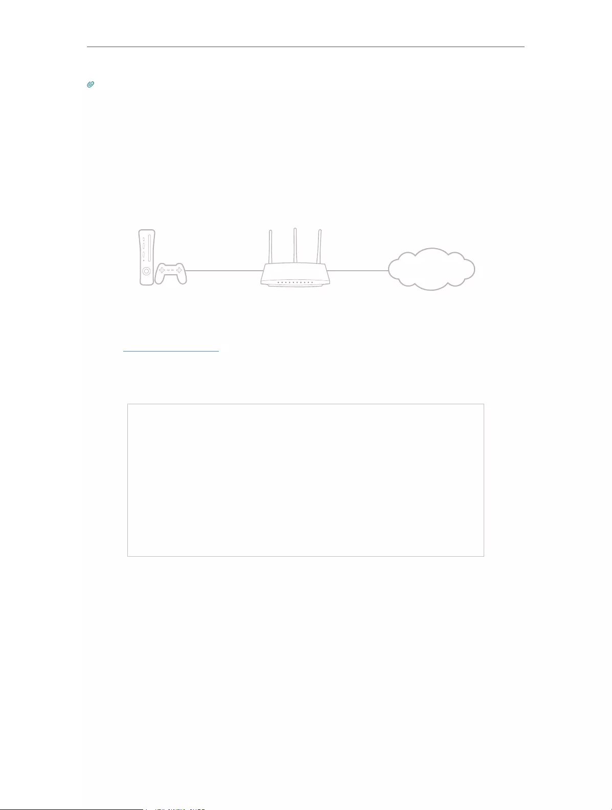
48
Chapter 9 NAT Forwarding
Tips:
• UPnP is enabled by default in this router.
• Only the application supporting UPnP protocol can use this feature.
• UPnP feature needs the support of operating system (e.g. Windows Vista/ Windows 7/ Windows 8, etc. Some of
operating system need to install the UPnP components).
For example, when you connect your Xbox to the router which has connected to
the internet to play online games, UPnP will send request to the router to open the
corresponding ports allowing the following data penetrating the NAT to transmit.
Therefore, you can play Xbox online games without a hitch.
XBOX Router
Internet
LAN WAN
If necessary, you can follow the steps to change the status of UPnP.
1. Visit http://tplinkwifi.net, and log in with the password you set for the router.
2. Go to Advanced > NAT Forwarding > UPnP and toggle on or off according to your
needs.

Chapter 10
VPN
The VPN (Virtual Private Networking) feature allows you to access your home network
in a secured way through internet when you are out of home.

50
Chapter 10 VPN
With IPSec VPN, you can access the network securely when out of home. To use the VPN
Service, you need to configure Dynamic DNS Service or assign a static IP address for
the router’s WAN port. And the System Time should be synchronized with the internet.
1. Visit http://tplinkwifi.net, and log in with the password you set for the router.
2. Go to Advanced > VPN > IPSec VPN.
3. Enable Dead Peer Detection.
4. Click Add and enter correspond parameters.
• IPSec Connection Name: Enter a name for the IPSec VPN connection.
• Remote IPSec Gateway (URL): Enter the destination gateway IP address which is the
public WAN IP or domain name of the remote VPN server endpoint.

51
Chapter 10 VPN
• Tunnel access from local IP addresses: Select Subnet Address if you want the whole
LAN to join the VPN network, or select Single Address if you want a single IP to join
the VPN network.
• IP Address for VPN: Enter the IP address of your LAN.
• Subnet Mask: Enter the subnet mask of your LAN.
• Tunnel access from remote IP addresses: Select Subnet Address if you want the
whole remote LAN to join the VPN network, or select Single Address if you want a
single IP to join the VPN network.
• IP Address for VPN: Enter the IP address of the remote LAN.
• IP Subnet Mask: Enter the subnet mask of the remote LAN.
• Key Exchange Method: Select Auto (IKE) or Manual to be used to authenticate IPSec
peers.
• Authentication Method: Select Pre-Shared Key (recommended).
• Pre-Shared Key: Create a pre-shared key to be used for authentication.
• Perfect Forward Secrecy: Select Enable or Disable as an additional security protocol
for the pre-shared key.
You can configure the advanced settings as needed. It’s recommended to keep the
default values. If you want to change these settings, make sure that both VPN server
endpoints use the same Encryption Algorithm, Integrity Algorithm, Diffie-Hellman
Group and Key Lifetime in both phase1 and phase2.
5. Click Save.

Chapter 11
Customize Your Network
Settings
This chapter guides you on how to configure advanced network features.
It contains the following sections:
• Change the LAN Settings
• Specify DHCP Server Settings
• Set Up a Dynamic DNS Service Account
• Create Static Routes
• Specify Wireless Settings
• Use WPS for Wireless Connection
• Schedule Your Wireless Function

53
Chapter 11 Customize Your Network Settings
11. 1. Change the LAN Settings
The router is preset with a default LAN IP 192.168.1.1, which you can use to log in to
its web management page. The LAN IP address together with the Subnet Mask also
defines the subnet that the connected devices are on. If the IP address conflicts with
another device on your local network or your network requires a specific IP subnet, you
can change it.
1. Visit http://tplinkwifi.net, and log in with the password you set for the router.
2. Go to Advanced > Network > LAN Settings.
3. Type in a new IP Address appropriate to your needs. And leave the Subnet Mask as
the default settings.
4. Click Save.
Note: If you have set the Virtual Server, DMZ or DHCP address reservation, and the new LAN IP address is not in the
same subnet with the old one, then you should reconfigure these features.
11. 2. Specify DHCP Server Settings
By default, the DHCP (Dynamic Host Configuration Protocol) Server is enabled and
the router acts as a DHCP server; it dynamically assigns TCP/IP parameters to client
devices from the IP Address Pool. You can change the settings of the DHCP Server if
necessary, and you can reserve LAN IP addresses for specified client devices.
1. Visit http://tplinkwifi.net, and log in with the password you set for the router.
2. Go to Advanced > Network > LAN Settings.
¾To specify the IP address that the router assigns:

54
Chapter 11 Customize Your Network Settings
1. Enable DHCP Server.
2. Enter the starting and ending IP addresses in the IP Address Pool.
3. Enter other parameters if the ISP offers. The Default Gateway is automatically filled in
and is the same as the LAN IP address of the router.
4. Click Save.
¾To reserve an IP address for a specified client device:
1. Click Add in the Address Reservation section.
2. Click Scan to find a connected device you want to apply this rule to. You can also
maunally enter the MAC address of the device if it’s currently disconnected from the
router.
3. Enter the IP address to reserve for the client device..
4. Tick the Enable This Entry checkbox and click Save.

55
Chapter 11 Customize Your Network Settings
11. 3. Set Up a Dynamic DNS Service Account
Most ISPs assign a dynamic IP address to the router and you can use this IP address
to access your router remotely. However, the IP address can change from time to time
and you don’t know when it changes. In this case, you might apply the DDNS (Dynamic
Domain Name Server) feature on the router to allow you and your friends to access your
router and local servers (FTP, HTTP, etc.) using a domain name without checking and
remembering the IP address.
Note: DDNS does not work if the ISP assigns a private WAN IP address (such as 192.168.1.x) to the router.
1. Visit http://tplinkwifi.net, and log in with the password you set for the router.
2. Go to Advanced > Network > Dynamic DNS.
3. Select the DDNS Service Provider: NO-IP or DynDNS. If you don’t have a DDNS
account, you have to register first by clicking Go to register. Then enter the username,
password and domain name of your account.
4. Click Log In and Save.
Tips: If you want to use a new DDNS account, please click Logout first, and then log in with a new account.
11. 4. Create Static Routes
Static routing is a form of routing that is configured manually by a network administrator
or a user by adding entries into a routing table. The manually-configured routing
information guides the router in forwarding data packets to the specific destination.
Visit multiple networks and servers at the same time.
For example, in a small office, my PC can surf the internet through
Router A, but I also want to visit my company’s network. Now I
have a switch and Router B. I connect the devices as shown in
the following figure so that the physical connection between my
PC and my company’s server is established. To surf the internet
and visit my company’s network at the same time, I need to
I want to:
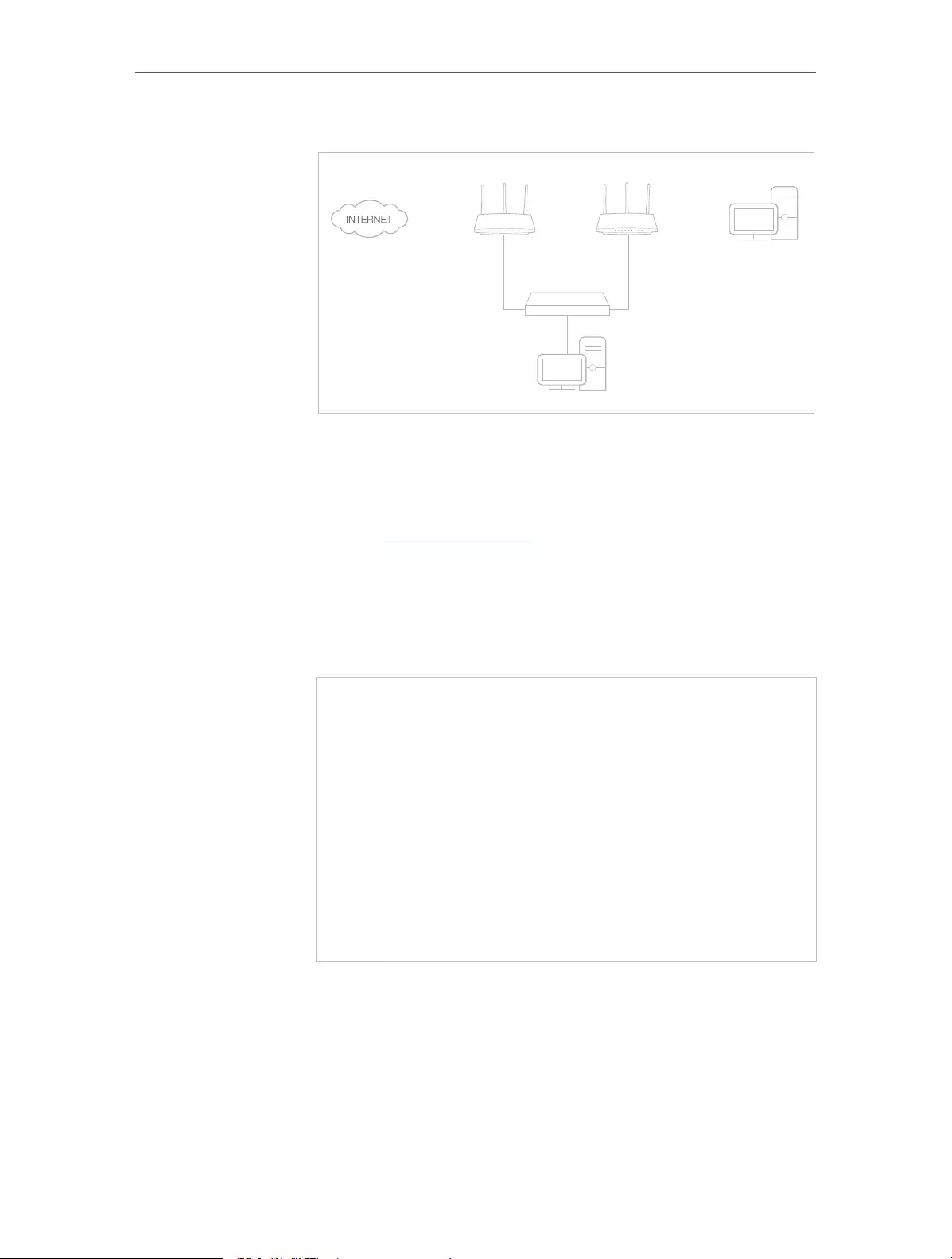
56
Chapter 11 Customize Your Network Settings
configure the static routing.
Company’s server
PC
Router B
Router A
Switch
LAN: 192.168.0.1
192.168.0.100
LAN: 192.168.0.2
WAN: 172.30.30.100
172.30.30.1
1. Change the routers’ LAN IP addresses to two different IP
addresses on the same subnet. Disable Router B’s DHCP
function.
2. Visit http://tplinkwifi.net, and log in with the password you
set for Router A.
3. Go to Advanced > Network > Static Routing.
4. Click Add and finish the settings according to the following
explanations:
Network Destination: The destination IP address that you want
to assign to a static route. This IP address cannot be on the same
subnet with the WAN IP or LAN IP of Router A. In the example,
the IP address of the company network is the destination IP
address, so here enter 172.30.30.1.
Subnet Mask: Determines the destination network with the
destination IP address. If the destination is a single IP address,
How can
I do that?

57
Chapter 11 Customize Your Network Settings
enter 255.255.255.255; otherwise, enter the subnet mask of
the corresponding network IP. In the example, the destination
network is a single IP, so here enter 255.255.255.255.
Default Gateway: The IP address of the gateway device to which
the data packets will be sent. This IP address must be on the
same subnet with the router’s IP which sends out data. In the
example, the data packets will be sent to the LAN port of Router
B and then to the Server, so the default gateway should be
192.168.0.2.
Interface: Determined by the port (WAN/LAN) that sends out
data packets. In the example, the data are sent to the gateway
through the LAN port of Router A, so LAN should be selected.
5. Click Save.
6. Check the System Routing Table below. If you can find the
entry you’ve set, the static routing is set successfully.
Open a web browser on your PC. Enter the company server’s IP
address to visit the company network.
11. 5. Specify Wireless Settings
The router’s wireless network name (SSID) and password, and security option are preset
in the factory. The preset SSID and password can be found on the label of the router.
You can customize the wireless settings according to your needs.
Visit http://tplinkwifi.net, and log in with the password you set for the router.
¾To enable or disable the wireless function:
1. Go to Basic > Wireless.
2. The wireless radio is enabled by default. If you want to disable the wireless function
of the router, just untick the Enable checkbox. In this case, all the wireless settings
will be invalid.
Done!

58
Chapter 11 Customize Your Network Settings
¾To change the wireless network name (SSID) and wireless password:
1. Go to Basic > Wireless.
2. Create a new SSID in Network Name (SSID) and customize the password for the
network in Password. The value is case-sensitive.
Note: If you change the wireless settings with a wireless device, you will be disconnected when the settings are
effective. Please write down the new SSID and password for future use.
¾To hide SSID:
1. Go to Basic > Wireless.
2. Select Hide SSID, and your SSID won’t display when you scan for local wireless
networks on your wireless device and you need to manually join the network.
¾To change the security option:
1. Go to Advanced > Wireless > Wireless Settings.
2. Select an option from the Security drop-down list. We recommend you don’t change
the default settings unless necessary. If you select other options, configure the
related parameters according to the help page.
In addition
• Mode — Select a transmission mode according to your wireless client devices. It is
recommended to just leave it as default.
• Channel Width — Select a channel width (bandwidth) for the wireless network.
• Channel — Select an operating channel for the wireless network. It is recommended
to leave the channel to Auto, if you are not experiencing the intermittent wireless
connection issue.
11. 6. Use WPS for Wireless Connection
Wi-Fi Protected Setup (WPS) provides an easier approach to set up a security-protected
Wi-Fi connection.
1. Visit http://tplinkwifi.net, and log in with the password you set for the router.
2. Go to Advanced > Wireless > WPS.
11. 6. 1. Use the WPS Wizard for Wi-Fi Connections
1. Click the Start WPS button on the screen. Within two minutes, press the WPS button
on the client device.

59
Chapter 11 Customize Your Network Settings
2. Success will appear on the above screen and the WPS LED on the router will keep on
for five minutes if the client has been successfully added to the network.
11. 6. 2. Use the PIN for Wi-Fi connections
Router’s PIN is enabled by default to allow wireless devices to connect to the router
using the PIN. You can use the default one or generate a new one.
You can also enter the PIN of the device you want to connect to the Wi-Fi.
Note:
• If you want to enable/disable the WPS feature, go to Advanced > Wireless > Advanced Settings. Locate the WPS
section and tick or untick the Enable checkbox.
• PIN (Personal Identification Number) is an eight—character identification number preset to each router. WPS supported
devices can connect to your router with the PIN. The default PIN is printed on the label of the router.
11. 7. Schedule Your Wireless Function
The wireless network can be automatically off at a specific time when you do not need
the wireless connection.

60
Chapter 11 Customize Your Network Settings
1. Visit http://tplinkwifi.net, and log in with the password you set for the router.
2. Go to Advanced > Wireless > Wireless Schedule.
3. Enable Wireless Schedule.
4. Click Add to set the wireless off time. Specfiy the time period and days whenthe
wireless network will be off.
5. Click Save.

Chapter 12
Manage the Router
This chapter will show you the configuration for managing and maintaining your router.
Some features are only supported by a certain mode.
It contains the following sections:
• Set Up System Time
• Change Operation Mode
• Test the Network Connectivity
• Upgrade the Firmware
• Backup and Restore Configuration Settings
• Auto Reboot
• Change the Login Password
• Local Management
• Remote Management
• System Log
• Monitor the Internet Traffic Statistics

62
Chapter 12 Manage the Router
12. 1. Set Up System Time
System time is the time displayed while the router is running. The system time you
configure here will be used for other time-based functions like Parental Controls.
1. Visit http://tplinkwifi.net, and log in with the password you set for the router.
2. Go to Advanced > System Tools > Time Settings.
¾To get time from the PC :
1. Click Get from PC.
2. Click Save.
¾To get time from the internet :
1. Select your local Time Zone from the drop-down list.
2. In the NTP Server I field, enter the IP address or domain name of your desired NTP
Server.
3. (Optional) In the NTP Server II field, enter the IP address or domain name of the
second NTP Server.
4. Click Get from the Internet and click Save.
¾To set up Daylight Saving Time:
1. Select Enable Daylight Saving Time.

63
Chapter 12 Manage the Router
2. Select the correct Start date and time when daylight saving time starts at your local
time zone.
3. Select the correct End date and time when daylight saving time ends at your local
time zone.
4. Click Save.
12. 2. Change Operation Mode
The router supports four operation works. Select one to best suit your network needs.
1. Visit http://tplinkwifi.net, and log in with the password you set for the router.
2. Go to Advanced > Operation Mode.
12. 3. Test the Network Connectivity
Diagnostics is used to test the connectivity between the router and the host or other
network devices.
1. Visit http://tplinkwifi.net, and log in with the password you set for the router.
2. Go to Advanced > System Tools > Diagnostics.
3. Click Start to begin the diagnostics.
12. 4. Upgrade the Firmware
TP-Link aims at providing better network experience for users.
We will inform you throught the web management page if there’s any update firmware
available for your router. Also, the latest firmware will be released at the TP-Link official
website www.tp-link.com, and you can download it from the Support page for free.

64
Chapter 12 Manage the Router
Note:
• Make sure you remove all attached USB devices from the router before the firmware upgrade to prevent data loss.
• Backup your router configuration before firmware upgrade.
• Do NOT turn off the router during the firmware upgrade.
12. 4. 1. Online Upgrade
1. Visit http://tplinkwifi.net, and log in with the password you set for the router.
2. When the latest firmware is available for your router, the update icon will display
in the top-right corner of the page. Click the icon to go to the Firmware Upgrade page.
Alternatively, you can go to Advanced > System Tools > Firmware Upgrade, and click
Check for upgrade to see whether the latest firmware is released.
3. Focus on the Online Upgrade section, and click Upgrade.
4. Wait a few minutes for the upgrade and reboot to complete.
Tips: If there’s a new and important firmware update for your router, you will see the notification (similar as shown
below) on your computer as long as a web browser is opened. Click Upgrade now, and log in to the web management
page with the password you set for the router. You will see the Firmware Upgrade page.
12. 4. 2. Manual Upgrade
1. Download the latest firmware file for the router from www.tp-link.com.
2. Visit http://tplinkwifi.net, and log in with or the password you set for the router.

65
Chapter 12 Manage the Router
3. Go to Advanced > System Tools > Firmware Upgrade.
4. Focus on the Device Information section. Make sure the downloaded firmware file is
matched with the Hardware Version.
5. Focus on the Local Upgrade section. Click Browse to locate the downloaded new
firmware file, and click Upgrade.
6. Wait a few minutes for the upgrade and reboot to complete.
12. 5. Backup and Restore Configuration Settings
The configuration settings are stored as a configuration file in the router. You can
backup the configuration file to your computer for future use and restore the router to
a previous settings from the backup file when needed. Moreover, if necessary you can
erase the current settings and reset the router to the default factory settings.
1. Visit http://tplinkwifi.net, and log in with your the password you set for the router.
2. Go to Advanced > System Tools > Backup & Restore.
¾To backup configuration settings:
Click Backup to save a copy of the current settings to your local computer. A ‘.bin’ file of
the current settings will be stored to your computer.
¾To restore configuration settings:
1. Click Browse to locate the backup configuration file stored on your computer, and
click Restore.
2. Wait a few minutes for the restoring and rebooting.

66
Chapter 12 Manage the Router
Note: During the restoring process, do not turn off or reset the router.
¾To reset the router to factory default settings:
1. Click Factory Restore to reset the router.
2. Wait a few minutes for the resetting and rebooting.
Note:
• During the resetting process, do not turn off or reset the router.
• We strongly recommend you backup the current configuration settings before resetting the router.
12. 6. Auto Reboot
Auto Reboot allows you to specify a time when the router will reboot automatically.
1. Visit http://tplinkwifi.net, and log in with the password you set for the router.
2. Go to Advanced > System Tools > Reboot.
3. Enable Auto Reboot.
4. Specify the time at which your router will reboot and the Auto Reboot Interval.
5. Click Save.
12. 7. Change the Login Password
The account management feature allows you to change your login password of the web
management page.
1. Visit http://tplinkwifi.net, and log in with the password you set for the router.

67
Chapter 12 Manage the Router
2. Go to Advanced > System Tools > Administration and focus on the Account
Management section.
3. Enter the old password, then a new password twice (both case-sensitive). Click Save.
4. Use the new password for future logins.
12. 8. Local Management
Local Management allows local devices to access and manage the router. By default, all
local devices can access and manage the router via HTTP.
1. Visit http://tplinkwifi.net, and log in with the password you set for the router.
2. Go to Advanced > System Tools > Administration and complete the settings In Local
Management section as needed.
3. Enable Local Management via HTTPS if you want to access the router via both HTTPS
and HTTP, or keep it disabled if you only want to access the router via HTTP.
4. Keep the Port for HTTP and Port for HTTPS as the default settings.
5. If you only want to allow one specific device to manage the router, enter the IP Address
or MAC Address of the device in the IP/MAC Address field.
6. Click Save.
Note: If a warning pops up when you visit https://tplinkwifi.net, click Trust (or a similar option) to continue.

68
Chapter 12 Manage the Router
12. 9. Remote Management
Remote Management allows remote devices to access and manage the router. By
default, all remote devices cannot access and manage the router.
1. Visit http://tplinkwifi.net, and log in with the password you set for the router.
2. Go to Advanced > System Tools > Administration and complete the settings in
Remote Management section as needed.
3. Enable Remote Management if you want to allow Remote Management via HTTPS, or
enable Remote Management and then disable Remote Management via HTTPS if you
want to allow Remote Management via HTTP.
4. Keep the Port as the default setting.
5. Decide which remote device can access the router remotely:
• Only the Following IP/MAC Address — Enter the IP Address or MAC Address of
the remote device to access the router.
• All — All remote devices can access the router.
6. Click Save.
Note: If a warning pops up when you visit the above address remotely, click Trust (or a similar option) to continue.
12. 10. System Log
When the router does not work normally, you can save the system log and send it to the
technical support for troubleshooting.
¾To save the system log locally:
1. Visit http://tplinkwifi.net, and log in the password you set for the router.
2. Go to Advanced > System Tools > System Log.

69
Chapter 12 Manage the Router
3. Choose the type and level of the system logs as needed.
4. Click Save Log to save the system logs to a local disk.

70
Chapter 12 Manage the Router
¾To send the system log to a remote server:
1. Visit http://tplinkwifi.net, and log in with the password you set for the router.
2. Go to Advanced > System Tools > System Log.
3. Click Log Settings.
4. Select Save Remotely. If the remote server has a log viewer client or a sniffer tool
implemented, you can view and analyze the system log remotely in real-time.
5. Select the minimum level of system logs to be saved from the drop-down list. The list
is in descending order, with the lowest level listed last.
6. Specify the IP address of the remote system log server in the Server IP field.
7. Specify the port number of the remote system log server in the Server Port field.
8. Select the local facility name of the remote server from the drop-down list.
9. Click Save.
12. 11. Monitor the Internet Traffic Statistics
The Traffic Statistics page displays the traffic usage of a device in the past 10 minutes
or that of all devices in the past 10 minutes/24 hours/7 days, allowing you to monitor
the volume of internet traffic statistics.
1. Visit http://tplinkwifi.net, and log in with the password you set for the router.
2. Go to Advanced > System Tools > Traffic Monitor.
3. Toggle on Traffic Monitor. You can monitor the traffic usage of a device in the past 10
minutes or that of all devices in the past 10 minutes/24 hours/7 days.

71
Chapter 12 Manage the Router

72
FAQ
Q1. What should I do if I forget my wireless password?
The default wireless password is printed on the label of the router. If the password has
been altered:
1. Connect your computer to the router using an Ethernet cable.
2. Visit http://tplinkwifi.net, and log in with the password you set for the router.
3. Go to Basic > Wireless to retrieve or reset your wireless password.
Q2. What should I do if I forget my web management password?
• Press and hold the WPS/Reset button of the router for about 5 seconds, and then visit
http://tplinkwifi.net to create a new login password.
Note: You’ll need to reconfigure the router to surf the internet once the router is reset, and please mark down your new
password for future use.
Q3. What should I do if I can’t log in to the router’s web management
page?
This can happen for a variety of reasons. Please try the methods below to log in again.
• Make sure your computer is connected to the router correctly and the corresponding
LED indicator(s) light up.
• Make sure the IP address of your computer is configured as Obtain an IP address
automatically and Obtain DNS server address automatically.
• Make sure http://tplinkwifi.net or http://192.168.1.1 is correctly entered.
• Check your computer’s settings:
1 ) Go to Start > Control Panel > Network and Internet, and click View network
status and tasks.
2 ) Click Internet Options on the bottom left.
3 ) Click Connections and select Never dial a connection.

73
4 ) Click LAN settings and deselect the following three options and click OK.
5 ) Go to Advanced > Restore advanced settings, click OK to save the settings.

74
• Use another web browser or computer to log in again.
• Reset the router to factory default settings and try again. If login still fails, please
contact the technical support.
Note: You’ll need to reconfigure the router to surf the internet once the router is reset.
Q4. What should I do if I can’t access the internet even though the
configuration is finished?
1. Visit http://tplinkwifi.net, and log in with the password you set for the router.
2. Go to Advanced > Status to check internet status:
As the follow picture shows, if IP Address is a valid one, please try the methods below
and try again:

75
• Your computer might not recognize any DNS server addresses. Please manually
configure the DNS server.
1 ) Go to Advanced > Network > LAN Settings.
2 ) Enter 8.8.8.8 as Primary DNS, click Save.
Tips: 8.8.8.8 is a safe and public DNS server operated by Google.
• Restart the modem and the router.
1 ) Power off your modem and router, and leave them off for 1 minute.
2 ) Power on your modem first, and wait about 2 minutes until it gets a solid cable
or internet light.
3 ) Power on the router.
4 ) Wait another 1 or 2 minutes and check the internet access.
• Reset the router to factory default settings and reconfigure the router.
• Upgrade the firmware of the router.

76
• Check the TCP/IP settings on the particular device if all other devices can get internet
from the router.
As the picture below shows, if the IP Address is 0.0.0.0, please try the methods below
and try again:
• Make sure the physical connection between the router and the modem is proper.
• Clone the MAC address of your computer.
1 ) Visit http://tplinkwifi.net, and log in with the password you set for the router.
2 ) Go to Advanced > Network > Internet (or EWAN Settings) and focus on the MAC
Clone section.
3 ) Choose an option as needed (enter the MAC address if Use Custom MAC
Address is selected), and click Save.
Tips:
• Some ISP will register the MAC address of your computer when you access the internet for the first time
through their Cable modem, if you add a router into your network to share your internet connection, the ISP will
not accept it as the MAC address is changed, so we need to clone your computer’s MAC address to the router.
• The MAC addresses of a computer in wired connection and wireless connection are different.
• Modify the LAN IP address of the router.

77
Note:
Most TP-Link routers use 192.168.0.1/192.168.1.1 as their default LAN IP address, which may conflict with the IP
range of your existing ADSL modem/router. If so, the router is not able to communicate with your modem and you
can’t access the internet. To resolve this problem, we need to change the LAN IP address of the router to avoid
such conflict, for example, 192.168.2.1.
1 ) Visit http://tplinkwifi.net, and log in with the password you set for the router.
2 ) Go to Advanced > Network > LAN Settings.
3 ) Modify the LAN IP address as the follow picture shows. Here we take 192.168.2.1
as an example.
4 ) Click Save.
• Restart the modem and the router.
1 ) Power off your modem and router, and leave them off for 1 minute.
2 ) Power on your modem first, and wait about 2 minutes until it get a solid cable
or internet light.
3 ) Power on the router.
4 ) Wait another 1 or 2 minutes and check the internet access.
• Double check the internet connection type.
1 ) Confirm your internet connection type, which can be learned from the ISP.
2 ) Visit http://tplinkwifi.net, and log in with or the password you set for the router.
3 ) Go to Advanced > Network > Internet (or EWAN Settings).
4 ) Select your Internet Connection Type and fill in other parameters.
5 ) Click Save.

78
6 ) Restart the modem and the router again.
• Please upgrade the firmware of the router.
If you’ve tried every method above but still cannot access the internet, please contact
the technical support.
Q5. What should I do if I can’t get internet access from the 3G/4G USB
modem?
• Go to our website at www.tp-link.com, click Support > Compatibility List > TL-MR3420
and make sure that your 3G/4G USB modem is on the compatibility list.
• Make sure that you have a valid SIM/UIM card inserted into the 3G/4G USB modem.
• Plug the 3G/4G USB modem directly into your computer and disable the PIN verification
via the modem utiltiy to check if you have the internet connection on your computer.
• Obtain the latest dial number and APN from your ISP, and update the information
through the router’s web management page.
Q6. What should I do if I can’t find my wireless network or I cannot
connect the wireless network?
If you fail to find any wireless network, please follow the steps below:
• Make sure the wireless function of your device is enabled if you’re using a laptop with
built-in wireless adapter. You can refer to the relevant document or contact the laptop
manufacturer.
• Make sure the wireless adapter driver is installed successfully and the wireless
adapter is enabled.
• On Windows 7

79
1 ) If you see the message No connections are available, it is usually because the
wireless function is disabled or blocked somehow.
2 ) Click Troubleshoot and windows might be able to fix the problem by itself.
• On Windows XP
1 ) If you see the message Windows cannot configure this wireless connection,
this is usually because windows configuration utility is disabled or you are
running another wireless configuration tool to connect the wireless.
2 ) Exit the wireless configuration tool (the TP-Link Utility, for example).
3 ) Select and right click on My Computer on desktop, select Manage to open
Computer Management window.
4 ) Expand Services and Applications > Services, find and locate Wireless Zero
Configuration in the Services list on the right side.
5 ) Right click Wireless Zero Configuration, and then select Properties.
6 ) Change Startup type to Automatic, click on Start button and make sure the
Service status is Started. And then click OK.
If you can find other wireless network except your own, please follow the steps below:
• Check the WLAN LED indicator on your wireless router/modem.
• Make sure your computer/device is still in the range of your router/modem. Move it
closer if it is currently too far away.
• Go to Advanced > Wireless > Wireless Settings, and check the wireless settings.
Double check your Wireless Network Name (SSID) is not hidden.
If you can find your wireless network but fail to connect, please follow the steps below:

80
• Authenticating problem/password mismatch:
1 ) Sometimes you will be asked to type in a PIN number when you connect to
the wireless network for the first time. This PIN number is different from the
Wireless Password/Network Security Key, usually you can only find it on the
label of your router.
2 ) If you cannot find the PIN or PIN failed, you may choose Connecting using a
security key instead, and then type in the Wireless Password/Network Security
Key.
3 ) If it continues to show note of Network Security Key Mismatch, it is suggested
to confirm the wireless password of your wireless router.
Note: Wireless Password/Network Security Key is case sensitive.
• Windows unable to connect to XXXX / Can not join this network / Taking longer than
usual to connect to this network:
• Check the wireless signal strength of your network. If it is weak (1~3 bars),
please move the router closer and try again.
• Change the wireless Channel of the router to 1, 6 or 11 to reduce interference
from other networks.
• Re-install or update the driver for your wireless adapter of the computer.

81
COPYRIGHT & TRADEMARKS
Specifications are subject to change without notice. is a registered trademark
of TP-Link Technologies Co., Ltd. Other brands and product names are trademarks or
registered trademarks of their respective holders.
No part of the specifications may be reproduced in any form or by any means or used
to make any derivative such as translation, transformation, or adaptation without
permission from TP-Link Technologies Co., Ltd. Copyright © 2018 TP-Link Technologies
Co., Ltd. All rights reserved.

82
CE Mark Warning
This is a class B product. In a domestic environment, this product may cause radio
interference, in which case the user may be required to take adequate measures.
OPERATING FREQUENCY (the maximum transmitted power)
2400 MHz -2483.5 MHz(20dBm)
EU declaration of conformity
TP-Link hereby declares that the device is in compliance with the essential requirements
and other relevant provisions of directives 2014/53/EU, 2009/125/EC and 2011/65/EU.
The original EU declaration of conformity may be found at http://www.tp-link.com/en/
ce
RF Exposure Information
This device meets the EU requirements (2014/53/EU Article 3.1a) on the limitation of
exposure of the general public to electromagnetic fields by way of health protection.
The device complies with RF specifications when the device used at 20 cm from your
body.
Canadian Compliance Statement
This device complies with Industry Canada license—exempt RSS standard(s). Operation
is subject to the following two conditions:
1. This device may not cause interference, and
2. This device must accept any interference, including interference that may cause
undesired operation of the device.
Le présent appareil est conforme aux CNR d’Industrie Canada applicables aux appareils
radio exempts de licence. L’exploitation est autorisée aux deux conditions suivantes :
1. l’appareil ne doit pas produire de brouillage;
2. l’utilisateur de l’appareil doit accepter tout brouillage radioélectrique subi, meme si
le brouillage est susceptible d’en compromettre le fonctionnement
Radiation Exposure Statement:
This equipment complies with IC radiation exposure limits set forth for an uncontrolled
environment. This equipment should be installed and operated with minimum distance
20cm between the radiator & your body.

83
Déclaration d’exposition aux radiations:
Cet équipement est conforme aux limites d’exposition aux rayonnements IC établies
pour un environnement non contrôlé. Cet équipement doit être installé et utilisé avec
un minimum de 20 cm de distance entre la source de rayonnement et votre corps.
Industry Canada Statement
CAN ICES-3 (B)/NMB-3(B)
Korea Warning Statements:
당해 무선설비는 운용중 전파혼신 가능성이 있음.
NCC Notice & BSMI Notice:
注意!
依據 低功率電波輻射性電機管理辦法
第十二條 經型式認證合格之低功率射頻電機,非經許可,公司、商號或使用者均
不得擅自變更頻率、加大功率或變更原設計之特性或功能。
第十四條 低功率射頻電機之使用不得影響飛航安全及干擾合法通信;經發現有干
擾現象時,應立即停用,並改善至無干擾時方得繼續使用。前項合法通信,指依
電信規定作業之無線電信。低功率射頻電機需忍受合法通信或工業、科學以及醫
療用電波輻射性電機設備之干擾。
安全諮詢及注意事項
• 請使用原裝電源供應器或只能按照本產品注明的電源類型使用本產品。
• 清潔本產品之前請先拔掉電源線。請勿使用液體、噴霧清潔劑或濕布進行
清潔。
• 注意防潮,請勿將水或其他液體潑灑到本產品上。
• 插槽與開口供通風使用,以確保本產品的操作可靠並防止過熱,請勿堵塞
或覆蓋開口。
• 請勿將本產品置放於靠近熱源的地方。除非有正常的通風,否則不可放在
密閉位置中。
• 請不要私自打開機殼,不要嘗試自行維修本產品,請由授權的專業人士進
行此項工作。
限用物質含有情況標示聲明書
產品元件名
稱
限用物質及其化學符號
鉛
Pb
鎘
Cd
汞
Hg
六價鉻
CrVI
多溴聯苯
PBB
多溴二苯醚
PBDE
PCB ○ ○ ○ ○ ○ ○
外殼 ○ ○ ○ ○ ○ ○
電源適配器 — ○ ○ ○ ○ ○

84
備考 1. « 超出 0.1 wt %» 及 « 超出 0.01 wt %» 系指限用物質之百分比含量超出百分
比含量基準值。
備考 2. « ○ « 系指該項限用物質之百分比含量未超出百分比含量基準值。
備考 3. «—» 系指該項限用物質為排除項目。
Продукт сертифіковано згідно с правилами системи УкрСЕПРО на відповідність
вимогам нормативних документів та вимогам, що передбачені чинними
законодавчими актами України.
Safety Information
• Keep the device away from water, fire, humidity or hot environments.
• Do not attempt to disassemble, repair, or modify the device.
• Do not use damaged charger or USB cable to charge the device.
• Do not use any other chargers than those recommended.
• Do not use the device where wireless devices are not allowed.
• Adapter shall be installed near the equipment and shall be easily accessible.
• Use only power supplies which are provided by manufacturer and in the original
packing of this product. If you have any questions, please don’t hesitate to contact us.
Please read and follow the above safety information when operating the device. We
cannot guarantee that no accidents or damage will occur due to improper use of the
device. Please use this product with care and operate at your own risk.
Explanations of the symbols on the product label
Symbol Explanation
DC voltage
Indoor use only
RECYCLING
This product bears the selective sorting symbol for Waste electrical and electronic equipment
(WEEE). This means that this product must be handled pursuant to European directive 2012/19/
EU in order to be recycled or dismantled to minimize its impact on the environment.
User has the choice to give his product to a competent recycling organization or to the retailer
when he buys a new electrical or electronic equipment.