

THANK YOU FOR YOUR PURCHASE . . .
Your JBL product has been designed to provide you with the performance and ease of operation you would expect from JBL.
• Please take time to read your owner’s manual in its entirety before operating or installing your amplifier.
• Keep the owner’s manual for your amplifier in your glove compartment along with the owner’s manual for your car.
• Put your amplifier sales receipt with other important documents in order to expedite warranty service if needed.
ABOUT THE MANUAL
This manual describes general installation guidelines and operation instructions. However, please note that proper installation of
mobile audio and video components requires qualified experience with mechanical and electrical procedures. If you do not have the
knowledge and tools to successfully perform this installation, we strongly recommend consulting an authorized JBL dealer about
your installation options. Keep all instructions and sales receipts for reference. Consider this manual as an indispensable feature
of your amplifier.

JBL CLUB
TABLE OF CONTENTS
CHAPTER 1: PICTORIAL INDEX OF INPUT CONNECTIONS …………………………………………………………………………………………. 01
CHAPTER 2: INSTALLATION AND WIRING …………………………………………………………………………………………. 02
What’s in the box …………………………………………………………………………………………. 02
Precautions …………………………………………………………………………………………. 02
1. Power indicator …………………………………………………………………………………………. 03
2. Protect indicator …………………………………………………………………………………………. 03
3. Speaker output connectors …………………………………………………………………………………………. 03
4. Fuses …………………………………………………………………………………………. 06
5. Power input connectors …………………………………………………………………………………………. 06
6. Front and rear inputs and outputs (RCA) …………………………………………………………………………………………. 07
7. Input level …………………………………………………………………………………………. 08
8. Crossover filter selectors …………………………………………………………………………………………. 08
9. Gain …………………………………………………………………………………………. 08
10. Crossover frequency controls …………………………………………………………………………………………. 08
11. HALOsonic input …………………………………………………………………………………………. 08
12. ADAS Assign (Club-704 and Club-4505) …………………………………………………………………………………………. 09
13. ADAS Input (Club-704 and Club-4505) …………………………………………………………………………………………. 09
CHAPTER 3: OPERATIONS …………………………………………………………………………………………. 10
CHAPTER 4: TROUBLESHOOTING …………………………………………………………………………………………. 11
CHAPTER 5: SPECIFICATIONS …………………………………………………………………………………………. 12
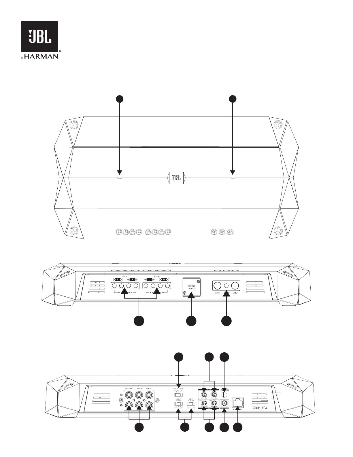
CHAPTER 1: PICTORIAL INDEX OF INPUT CONNECTIONS
Club Amplifier top panel
Club Amplifier front panel
1
POWER
2
PROTECT
Club Amplifier back panel
1
3
4 5
7
6
8
9
10
11
12
—
13
JBL CLUB
CHAPTER 2: INSTALLATION AND WIRING
What’s in the box:
1 amplifier
2 spare fuses (x3 with Club-4505)
4 RCA adapters (x2 with Club-5501)
Quick-start guide
Precautions:
IMPORTANT: Disconnect the vehicle’s negative (–) battery terminal before beginning the installation.
• Always wear protective eyewear when using tools.
• Choose a safe mounting location, away from moisture. Check clearances on both sides of a planned mounting surface. Be sure that screws
or wires will not puncture brake lines, fuel lines, or wiring harnesses and that wire routing will not interfere with the safe vehicle
operation. Use caution when drilling or cutting in the mounting area.
• When making electrical connections, make sure they are secure and properly insulated.
• If you must replace any of the amplifier’s fuses, use the same type of fuse and current rating as the original.
• To keep the amplifier cool, choose a location that provides enough air circulation, such as under a seat or in the trunk.
• Do not mount the amplifier with the heat sink facing downward, as this interferes with cooling.
• Mount the amplifier so that it will not be damaged by the feet of backseat passengers or shifting cargo in the trunk, and so that it
remains dry.
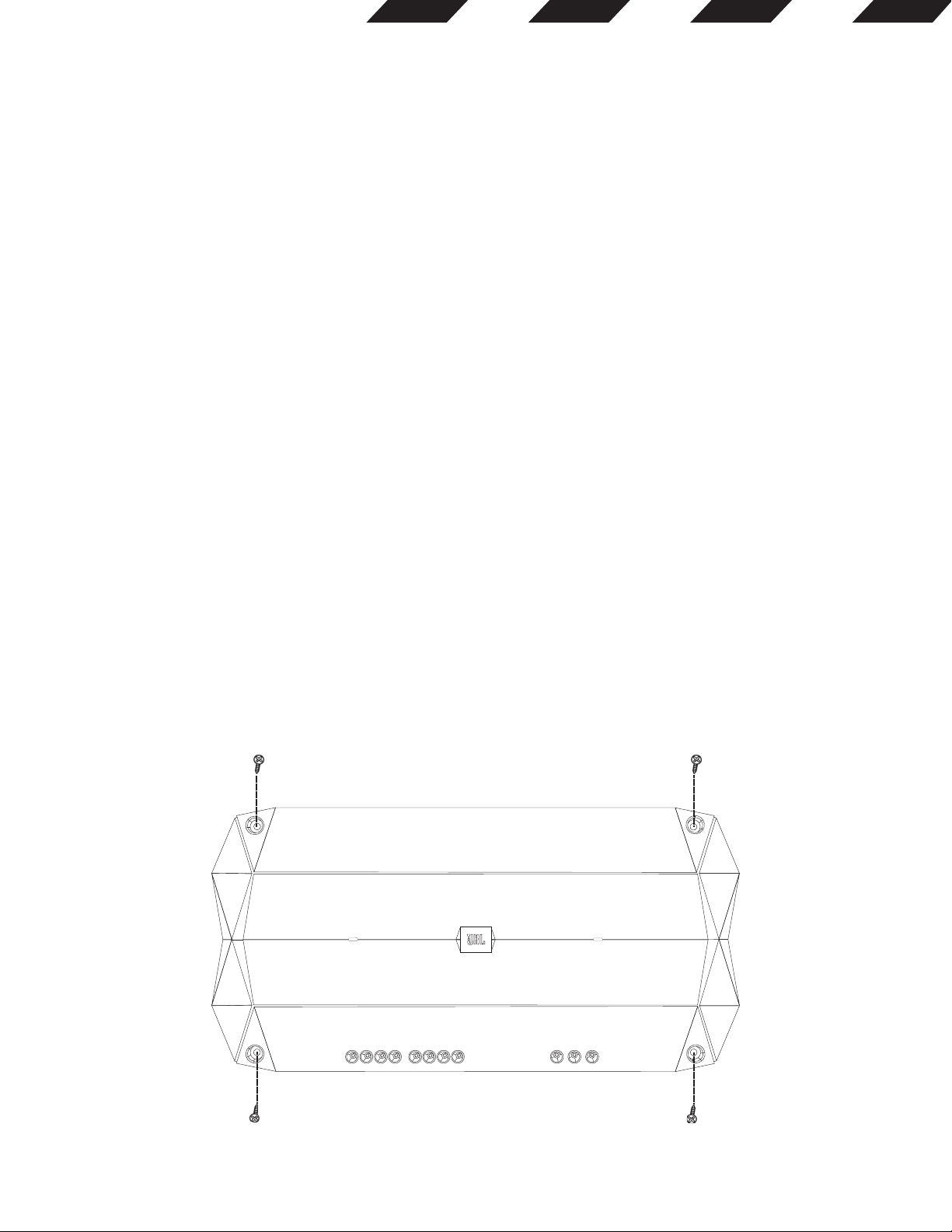
• Using the amplifier as a template, mark the locations of the holes on the mounting surface.
• Drill pilot holes in the mounting surface.
• Attach the amplifier to the mounting surface with four appropriate mounting screws (not included). Recommended: #8 Phillips-head
sheet metal screws.
POWER
NOTE: You may find it more convenient to make all of the connections to the amplifier before you permanently mount it.
PROTECT
2
EN
OWNER’S MANUAL
JBL Club-704/ Club-4505/Club-5501
AMPLIFIERS
THANK YOU FOR YOUR PURCHASE . . . Your JBL product has been designed to provide you with the performance and ease of operation you would expect from JBL.
Please take time to read your owner’s manual in its entirety before operating or installing your amplifier.
Keep the owner’s manual for your amplifier in your glove compartment along with the owner’s manual for your car.
Put your amplifier sales receipt with other important documents in order to expedite warranty service if needed.
ABOUT THE MANUAL This manual describes general installation guidelines and operation instructions. However, please note that proper installation of mobile audio and video components requires qualified experience with mechanical and electrical procedures. If you do not have the knowledge and tools to successfully perform this installation, we strongly recommend consulting an authorized JBL dealer about your installation options. Keep all instructions and sales receipts for reference. Consider this manual as an indispensable feature of your amplifier.
JBL CLUB TABLE OF CONTENTS CHAPTER 1: PICTORIAL INDEX OF INPUT CONNECTIONS …………………………………………………………………………………………. 01
CHAPTER 2: INSTALLATION AND WIRING …………………………………………………………………………………………. 02
What’s in the box …………………………………………………………………………………………. 02 Precautions …………………………………………………………………………………………. 02 1. Power indicator …………………………………………………………………………………………. 03 2. Protect indicator …………………………………………………………………………………………. 03 3. Speaker output connectors …………………………………………………………………………………………. 03 4. Fuses …………………………………………………………………………………………. 06 5. Power input connectors …………………………………………………………………………………………. 06 6. Front and rear inputs and outputs (RCA) …………………………………………………………………………………………. 07 7. Input level …………………………………………………………………………………………. 08 8. Crossover filter selectors …………………………………………………………………………………………. 08 9. Gain …………………………………………………………………………………………. 08 10. Crossover frequency controls …………………………………………………………………………………………. 08 11. HALOsonic input …………………………………………………………………………………………. 08 12. ADAS Assign (Club-704 and Club-4505) …………………………………………………………………………………………. 09 13. ADAS Input (Club-704 and Club-4505) …………………………………………………………………………………………. 09
CHAPTER 3: OPERATIONS …………………………………………………………………………………………. 10
CHAPTER 4: TROUBLESHOOTING …………………………………………………………………………………………. 11
CHAPTER 5: SPECIFICATIONS …………………………………………………………………………………………. 12
1
CHAPTER 1: PICTORIAL INDEX OF INPUT CONNECTIONS
Club Amplifier top panel
Club Amplifier front panel
Club Amplifier back panel
POWER PROTECT
1 2
3 4 5
8 10 12 13
1197
6
—
JBL CLUB
2
CHAPTER 2: INSTALLATION AND WIRING
What’s in the box: 1 amplifier 2 spare fuses (x3 with Club-4505) 4 RCA adapters (x2 with Club-5501) Quick-start guide
Precautions:
IMPORTANT: Disconnect the vehicles negative () battery terminal before beginning the installation. Always wear protective eyewear when using tools. Choose a safe mounting location, away from moisture. Check clearances on both sides of a planned mounting surface. Be sure that screws or wires will not puncture brake lines, fuel lines, or wiring harnesses and that wire routing will not interfere with the safe vehicle operation. Use caution when drilling or cutting in the mounting area. When making electrical connections, make sure they are secure and properly insulated. If you must replace any of the amplifiers fuses, use the same type of fuse and current rating as the original. To keep the amplifier cool, choose a location that provides enough air circulation, such as under a seat or in the trunk. Do not mount the amplifier with the heat sink facing downward, as this interferes with cooling. Mount the amplifier so that it will not be damaged by the feet of backseat passengers or shifting cargo in the trunk, and so that it remains dry. Using the amplifier as a template, mark the locations of the holes on the mounting surface. Drill pilot holes in the mounting surface. Attach the amplifier to the mounting surface with four appropriate mounting screws (not included). Recommended: #8 Phillips-head sheet metal screws.
NOTE: You may find it more convenient to make all of the connections to the amplifier before you permanently mount it.
POWER PROTECT
3
1. Power indicator:
The light will illuminate in white when the amp is receiving power and playing.
2. Protect indicator:
The indicator will illuminate in red if the amp enters Protect mode in the event of conditions such as over/under voltage, short circuit, amplifier output circuit failure, or excessive heat.
3. Speaker Output Connectors: Connect the speakers to these terminals, observing proper polarity (connect each speakers positive (+) lead to the appropriate positive
(+) terminal, and negative (-) lead to the appropriate negative (-) terminal.
The Club-704 features Front L+, L-, R+, and R- terminals, and Rear L+, L-, R+, and R- terminals.
4-channel operation: Connect the front left speaker to the Front L+ and L- terminals, and the front right speaker to the Front R+ and R- terminals. Connect the rear left speaker to the Rear L+ and L- terminals, and the rear right speaker to the Rear R+ and R- terminals.
Left Front speaker Right Front speaker
Left rear speaker Right rear speaker
JBL CLUB
4
3-channel operation: Connect the stereo speakers to the Front terminals, as described above. Connect the single speakers + lead to the Rear L+ terminal, and the — lead to the Rear R- terminal.
2-channel (bridged) operation: Connect one speakers + lead to the Front L+ terminal, and the — lead to the Front R- terminal. Connect the other speakers + lead to the Rear L+ terminal, and the — lead to the Rear R- terminal.
Right Front speakerLeft Front speaker
4-ohm subwoofer
4-ohm subwoofer 4-ohm subwoofer
5
The Club-4505 features Front L+, L-, R+, and R- terminals; Rear L+, L-, R+, and R- terminals; and Sub + and — terminals.
5-channel operation: Connect the front left speaker to the Front L+ and L- terminals, and the front right speaker to the Front R+ and R- terminals. Connect the rear left speaker to the Rear L+ and L- terminals, and the rear right speaker to the Rear R+ and R- terminals. Connect the subwoofers positive (+) lead to the + terminal, and the negative (-) lead to the — terminal.
3-channel (front and rear bridged) operation: Connect one speakers + lead to the Front L+ terminal, and the — lead to the Front R- terminal. Connect the other speakers + lead to the Rear L+ terminal, and the — lead to the Rear R- terminal. Connect the subwoofers positive (+) lead to the + terminal, and the negative (-) lead to the terminal.
Left front speaker
Left rear speaker
Right front speaker
Right rear speaker
4-ohm subwoofer
Front speaker
Rear speaker
4-ohm subwoofer
JBL CLUB The Club-5501 features two positive (+) and two negative (-) terminals. To power two subwoofers in parallel, connect one subs positive (+)
and negative (-) leads to the positive and negative terminals on the left, and the other subs positive and negative leads to the positive and negative terminals on the right. To power two subwoofers in series, connect one subs positive (+) lead to the positive terminal on the left, and the other subs negative (-) lead to the negative terminal on the right, then connect left subs negative lead to the right subs positive lead.
NOTE: Minimum speaker impedance for stereo full-range and subwoofer operation is 2ohms. Minimum speaker impedance for bridged operation is 4ohms.
4. Fuses: Replace only with fuses of the same amperage:
Club-704, Club-5501: 30A Club-4505: 30A
5. Power Input Connectors: Power: Run power wire from the +12V input to the positive terminal of the vehicles battery. Install an appropriate fuse holder and fuse (60A minimum
on Club-704 and Club-5501, 105A minimum on Club-4505) within 18 (457mm) of the battery. Make sure the wire is not damaged or pinched during installation. Install protective grommets when routing wires through the bulkhead or other sheet metal. Use larger-gauge wiring for longer runs.
Club-704 minimum wire size: 10 gauge Club-4505, Club-5501 minimum wire size: 8 gauge
6
If youre connecting only one sub, you can use either set of positive and negative terminals.
4-ohm subwoofer
2-ohm subwoofer 2-ohm subwoofer
PARALLEL WIRING
SERIES WIRING
4-ohm subwoofer
7
Use a small Phillips screwdriver to loosen the adapters set screws and insert the speaker wires into the holes on the back of the adapter. Tighten the set screws to secure the wires.
Always connect the (+) speaker wire to the adapters (+) terminal and the () speaker wire to the adapters () terminal. When all wires are connected, plug the adapters into the Club amplifiers FRONT (and REAR, if using the 4-channel amplifier) preamp inputs.
Remote: Connect a 20-gauge wire from the Remote Out lead of the source unit to the REM input. This lead turns the amplifier on when using low-level input signals.
Ground: Run a wire (the same gauge as the power wire) from the GND input to a factory bolt in the vehicles chassis (see illustration below). NOTE: Remove any paint from the chassis for best contact. Use a star washer below the ring connector for a secure connection.
6. Front and rear inputs and outputs (RCA): If your source unit offers preamp outputs, connect to the FRONT, REAR, and/or SUB inputs using RCA patch cables.
To connect a second amp directly to the Club-704 amplifier, run a patch cable from the PRE OUT outputs to the second amps preamp inputs.
If your car audio systems head unit does not have line-level outputs: Use the supplied bare wire-to-RCA adapters to connect the Club amplifiers inputs to either the front or the rear speaker outputs of your car audio systems head unit (splice crimps not included).
Important: Some factory-installed audio system amplifiers include electronic filters that limit the amount of bass sent to the systems smaller speakers. This filtering will adversely affect the Club amps performance. To get the most bass possible from your Club amp, splice the bare wire-to-RCA adapters into the factory system speaker outputs that are connected to the systems largest speakers (the ones designed to make the most bass).
Factory Bolt Ring Connector Ground Wire
Note: Remove any paint below ring connector
Star Washer
Loosen Screws
Insert Wires
Tighten Screws
JBL CLUB
8
9. Input level selectors (GAIN): Input level controls. Use these to match the amps input sensitivity to the output level of your source unit. See 17 for a recommended adjustment procedure. (See Setting the input levels in Chapter 3 for a recommended adjustment procedure.)
10. Crossover-filter frequency controls (FREQ): Crossover-filter frequency controls. Turn the dials to the left to lower the crossover point, and to the right to raise the crossover point. Crossover point settings vary by listener preference.
11. HALOsonic:
Lets you plug in an optional cable into your vehicles HALOsonic system (if present). Also functions as a full-range mixing input.
7. Input level:
Use this switch along with the gain control to set the Club amplifiers input level. If use an aftermarket radios RCA-level outputs, set the Input Level switch to the LO position. If using high-level outputs, start the control-setting process with the Input Level switch set in the HI1 position.
Note: If you have connected your Club amplifier to a factory audio systems speaker outputs, the audio signal may fail to play. If this happens, change the Input Level switch to the HI2 position. The HI2 position includes a circuit designed to fool this type of factory audio system into seeing a speaker connected to its input.
Important: The HI2 setting should never be used when the Club amplifier is connected to an aftermarket head units line-level (RCA-type) outputs.
8. Crossover filter selectors (X-OVER):
Crossover-filter selectors (Club-704 and Club-4505 only; Club-5501 filter is low pass only).
LP: Low pass. Choose this setting if youre connecting a subwoofer(s), or want to provide a low-pass filter for separate mid-bass speakers.
FULL: Full range. Choose this setting if youre connecting full-range speakers, and not using a subwoofer in your system.
HP: High pass. Choose this setting to prevent low bass from reaching midrange or full-range speakers when youre using a subwoofer in your system. (See setting the crossovers in Chapter 3.)
PRE OUT REAR FRONT
From high-level source
9
1 2 3 4 5 6 7 8
1 2 3 4 5 6 7 8
12. ADAS ASSIGN (Club-704 and Club-4505 models only):
If youve connected the amp to an Advanced Driver Assistance System (see 13, next), this dial allows you to select the speaker over which youll hear ADAS messages. Turn the dial to FL for the front left speaker, FR for the front right, RL for the rear left, and RR for the rear right.
13. ADAS INPUT (Club-704 and Club-4505 only):
Lets you plug a T568B cable (sold separately) from an optional Advanced Driver Assistance System into the amps RJ45 input jack. Also functions as a priority switching input.
When the system issues a warning or message, the amp will mute the music and play it over the speaker youve selected with the ADAS ASSIGN dial (see 12, previous).
ADAS input channel sequence:
1. FL+ 2. FL- 3. FR+ 4. RL- 5. RL+ 6. FR- 7. RR+ 8. RR-
Four group signal: 1-2, 3-6, 5-4, 7-8
T568B plug
RJ45 input
T568B cable
JBL CLUB CHAPTER 3: OPERATIONS
Setting the input levels:
To match your amplifiers input sensitivity (gain) to your source units output level, we recommend the following procedure:
A. Turn both input level controls counterclockwise to MIN (minimum).
B. Play a dynamic music track through your source unit. Turn the source units volume control to the 3/4 position.
C. Turn the front input level control dial clockwise towards MAX until you hear distortion in the music (its no longer clear).
D. Slowly turn the front level input control dial counterclockwise until the music sounds clear again.
E. Your front input level is now correctly set. Repeat this process with the rear channels.
Setting the crossover
Properly setting crossover filter selectors optimizes frequency distribution for efficient speaker operation and best sound.
Step 1: Use the slider controls to select low-pass (LP), FULL, or high-pass (HP).
LP: Low pass. Choose this setting if you are connecting a subwoofer(s) or want to provide a low-pass filter for separate mid-bass speakers.
FULL: Full range. Choose this setting if you are connecting full-range speakers and are not using a subwoofer in your system.
HP: High pass. Choose this setting to prevent low bass from reaching midrange or full-range speakers when you are using a subwoofer in your system.
Step 2: Use crossover-filter frequency controls to adjust crossover point settings for coaxial speakers and subwoofers to suit listener preference. Turn the dials to the left to lower the crossover point and to the right to raise the crossover point. Exact crossover settings for coaxial speakers and subwoofers finally depend on your listening preferences. NOTE: crossover point does not apply in FULL mode.
Adjusting the subwoofer:
Select INT if youre connecting a subwoofer to the Club-4505 amplifier, but your source unit does not feature a subwoofer output (this will send a summed audio signal to the subwoofer). If your source unit does feature a subwoofer output, select EXT to connect to that output.
A B C D E
SUB INPUT
INT EXT
10
11
CHAPTER 4: TROUBLESHOOTING
PROBLEM: No audio and POWER INDICATOR is off.
CAUSE and SOLUTION: No voltage at BATT+ and/or REM terminals, or bad or no ground connection. Check voltages at amplifier terminals with VOM.
PROBLEM: No audio and PROTECT INDICATOR flashes every 4 seconds.
CAUSE and SOLUTION: DC voltage on amplifier output. Amplifier may need service; see enclosed warranty card for service information.
PROBLEM: No audio and PROTECT INDICATOR is on.
CAUSE and SOLUTION: Amplifier is overheated. Make sure amplifier cooling is not blocked at mounting location. Verify that speaker-system impedance is within specified limits. Or, there may be voltage greater than 16V (or less than 8.5V) on BATT+ connection. Check vehicle charging system.
PROBLEM: No audio and PROTECT and POWER INDICATORS flash.
CAUSE and SOLUTION: Voltage less than 9V on BATT+ connection. Check vehicle charging system.
PROBLEM: Distorted audio.
CAUSE and SOLUTION: Gain is not set properly. Check INPUT LEVEL setting. Check speaker wires for shorts or grounds. Amplifier or source unit may be defective.
PROBLEM: Distorted audio and PROTECT INDICATOR flashes.
CAUSE and SOLUTION: Short circuit in speaker or wire. Remove speaker leads one at a time to locate shorted speaker or wire, and repair.
Selecting the subwoofer phase
You can choose a subwoofer phase output of 0 or 180. To check your sub’s phase, play music with lots of bass and listen as another person slowly flips the 0/180 degree phase switch back and forth. The correct setting is the one that gives you more bass. If you don’t detect any real difference, leave the switch in the 0 setting.
Boosting the bass
Turn the dial clockwise to increase the bass output from 0 dB to +9 dB.
PHASE
0 180
BASS BOOST
0dB +9dB
JBL CLUB
12
PROBLEM: Music lacks dynamics or «punch.»
CAUSE and SOLUTION: Speakers are not connected properly. Check speaker connections for proper polarity.
PROBLEM: Amplifier fuse keeps blowing.
CAUSE and PROBLEM: The wiring is connected incorrectly or there is a short circuit. Review installation precautions and procedures in manual. Check wiring connections.
PROBLEM: Engine noisewhining or clickingin system when the engine is on.
CAUSE and PROBLEM: Amplifier is picking up alternator noise. Turn down gain. Move audio cables away from power wires. Install an alternator noise filter on power line between battery and alternator. Check ground connections on the amplifier since a loose or improper ground is one of the main causes for extraneous noise in your audio system.
CHAPTER 5: SPECIFICATIONS
Model RMS power @
4 ohms RMS power @
2 ohms RMS bridged power @
4 ohms Total peak
power Frequency response
Maximum signal input
Maximum sensitivity
Club-704 70W x 4 100W x 4 200W x 2 1000W 10Hz-40kHz 20V 200mV
Club-4505 45W x 4 65W x 4 130 x 2
1800W 10Hz-40kHz (full range)
20V 200mV 320W x 1 500W x 1 / 10Hz-320Hz (sub)
Club-5501 370W x 1 550 x 1 / 1300W 10Hz-320Hz 20V 200mV
Model Line in signal-to-noise ratio
(reference to 1 watt) THD+N at rated power
(20Hz — 20kHz) Product dimensions
(L x W x H) Shipping weight Fuse size
Operating voltage
Club-704 85dB 1% 375 x 189.4 x 59mm
14-13/16″ x 7-1/2″ x 2-3/8″ 4.1kg(9.1lbs) 30A x 2 9-16VDC
Club-4505 Full:85dB
1% 400×189.4x59mm
15-3/4″ x 7-1/2″ x 2-3/8″ 3.3kg(lbs) 30A x 3 9-16VDC
Sub:80dB
Club-5501 80dB 1% 243.5 x 189.4 x 59mm
9-5/8″ x 7-1/2″ x 2-3/8″ 4.7kg(10.4lbs) 30A x 2 9-16VDC
13
2016 HARMAN International Industries, Incorporated. All rights reserved. Infinity is a trademark of HARMAN International Industries, Incorporated, registered in the United States and/or other countries. The Bluetooth word mark and logos are registered trademarks owned by Bluetooth SIG, Inc. and any use of such marks by HARMAN International Industries, Incorporated is under license. Other trademarks and trade names are those of their respective ow
Русский
- Bedienungsanleitung JBL Club-704
- JBL Club-704 User Manual
- Manual Usuario JBL Club-704
- Mode d’emploi JBL Club-704
- Istruzioni JBL Club-704
- инструкция JBL Club-704
- JBL Club-704の取扱説明書
- Handleiding JBL Club-704
- Manual de uso JBL Club-704
Вам нужна инструкция? Мы поможем Вам ее найти и сэкономить Ваше время.
- 16 stron
- 1.64 mb
Изделие JBL Club-704, а также другие, которыми Вы пользуетесь ежедневно, наверняка вы получили в комплекте с инструкцией обслуживания. Из опыта наших пользователей мы знаем, что большинство из Вас не уделили этому особого внимания. Большая часть инструкций, сразу же после покупки попадает в корзину для мусора вместе с коробкой — это ошибка. Ознакомьтесь с информацией, касающейся инструкции JBL Club-704, которая поможет Вам в будущем сэкономить нервы и избежать головной боли.
Важная подсказка — не забывайте хотя бы раз прочитать инструкцию JBL Club-704
Если вы не хотите каждый раз читать информационные брошюры, касающиеся, тех или JBL Club-704 иных изделий, достаточно, прочитать их раз — сразу же после покупки устройства. Вы получите основное знания, касающиеся поддержания изделия JBL Club-704 в хорошем эксплуатационном состоянии, так, чтобы без проблем достигнуть его планируемого цикла работы. Затем инструкцию можно отложить на полку и вернуться к ней только в случае, если вы не уверены, правильно ли проводится техобслуживание изделия. Правильный уход является необходимым элементом Вашего удовольствия JBL Club-704.
Раз в году пересмотрите шкафчик, в котором держите инструкции для всех устройств, — выбросите те, которыми вы уже не пользуетесься. Это поможет Вам сохранять порядок в своей домашней базе инструкций обслуживания.
Summary of Contents for JBL Club-704
Что находится в инструкции JBL Club-704? Почему стоит ее прочитать?
- Гарантия и подробности, касающиеся техобслуживания изделия
Хорошей идеей будет прикрепить чек к странице инструкции. Если что-то плохое случится во время использования JBL Club-704, у вас будет комплект документов, необходимый для гарантийного ремонта. В этой части инструкции вы найдете информацию об авторизованных сервисных центрахJBL Club-704 а также, как самостоятельно правильно ухаживать за оборудованием — так, чтобы не потерять гарантийных прав. - Указания по монтажу и Setup
Не терять нервов и времени на самостоятельную попытку установки и первого запуска изделия. Воспользуйтесь рекомендациями производителя JBL Club-704 чтобы правильно запустить изделие, без лишнего риска повреждения оборудования. - Информация, касающаяся дополнительных запчастей (входящих в комплект а также являющихся опцией)
Пересматривая эту часть документа вы сможете проверить, доставлен ли ваш JBL Club-704 с полним комплектом аксессуаров. Вы также сможете узнать, какие дополнительные запчасти или аксессуары для JBL Club-704 Вы сможете найти и докупить к своему устройству. - Troubleshooting
Самые частые проблемы, касающиеся JBL Club-704 и методы их решения. Это очень полезная часть руководства по обслуживанию — она позволит Вам сэкономить много времени на поиск решений. 90% проблем с JBL Club-704 повторяется у многих пользователей. - Требования, касающиеся питания и энергетический класс
Информация, касающаяся количества потребляемой энергии, а также рекомендации, касающиеся установки и питания JBL Club-704. Прочитайте, чтобы оптимально пользоваться JBL Club-704 и не использовать большего количества ресурсов, нежели это необходимо для правильной работы изделия. - Специальные функции JBL Club-704
Здесь вы можешь узнать, как персонализировать изделие JBL Club-704. Вы узнаете, какие дополнительные функции могут помочь Вам удобно использовать продукт JBL Club-704 а также, какие функции Вашего устройства оптимальны для выполнения конкретной деятельности.
Как видите в инструкции вы найдете информацию, которая реально поможет Вам в использовании Вашего изделия. Стоит с ней ознакомиться, чтобы избежать разочарований, возникающих из более короткого, нежели предусматривалось, периода исправности изделия JBL Club-704. Если все же вы не хотите копить инструкции в своем доме, наш сайт поможет Вам в этом — вы должны найти у нас руководство по обслуживанию большинства из своих устройств, а также JBL Club-704.
Комментарии (0)
Хорошее руководство по эксплуатации
Законодательство обязывает продавца передать покупателю, вместе с товаром, руководство по эксплуатации JBL Club-704. Отсутствие инструкции либо неправильная информация, переданная потребителю, составляют основание для рекламации в связи с несоответствием устройства с договором. В законодательстве допускается предоставлении руководства в другой, чем бумажная форме, что, в последнее время, часто используется, предоставляя графическую или электронную форму инструкции JBL Club-704 или обучающее видео для пользователей. Условием остается четкая и понятная форма.
Что такое руководство?
Слово происходит от латинского «instructio», тоесть привести в порядок. Следовательно в инструкции JBL Club-704 можно найти описание этапов поведения. Цель инструкции заключается в облегчении запуска, использования оборудования либо выполнения определенной деятельности. Инструкция является набором информации о предмете/услуге, подсказкой.
К сожалению немного пользователей находит время для чтения инструкций JBL Club-704, и хорошая инструкция позволяет не только узнать ряд дополнительных функций приобретенного устройства, но и позволяет избежать возникновения большинства поломок.
Из чего должно состоять идеальное руководство по эксплуатации?
Прежде всего в инструкции JBL Club-704 должна находится:
— информация относительно технических данных устройства JBL Club-704
— название производителя и год производства оборудования JBL Club-704
— правила обслуживания, настройки и ухода за оборудованием JBL Club-704
— знаки безопасности и сертификаты, подтверждающие соответствие стандартам
Почему мы не читаем инструкций?
Как правило из-за нехватки времени и уверенности в отдельных функциональностях приобретенных устройств. К сожалению само подсоединение и запуск JBL Club-704 это слишком мало. Инструкция заключает ряд отдельных указаний, касающихся функциональности, принципов безопасности, способов ухода (даже то, какие средства стоит использовать), возможных поломок JBL Club-704 и способов решения проблем, возникающих во время использования. И наконец то, в инструкции можно найти адресные данные сайта JBL, в случае отсутствия эффективности предлагаемых решений. Сейчас очень большой популярностью пользуются инструкции в форме интересных анимаций или видео материалов, которое лучше, чем брошюра воспринимаются пользователем. Такой вид инструкции позволяет пользователю просмотреть весь фильм, не пропуская спецификацию и сложные технические описания JBL Club-704, как это часто бывает в случае бумажной версии.
Почему стоит читать инструкции?
Прежде всего здесь мы найдем ответы касательно конструкции, возможностей устройства JBL Club-704, использования отдельных аксессуаров и ряд информации, позволяющей вполне использовать все функции и упрощения.
После удачной покупки оборудования/устройства стоит посвятить несколько минут для ознакомления с каждой частью инструкции JBL Club-704. Сейчас их старательно готовят или переводят, чтобы они были не только понятными для пользователя, но и чтобы выполняли свою основную информационно-поддерживающую функцию.
Are you looking for the manual for JBL Club-704? You are in the right place. Below the document viewer for JBL Club-704 manual in PDF format. To save your time, we say that the most common problems with JBL Club-704 can be found in the manual in the «Troubleshooting» section. Check the appropriate page number in the table of contents, and then enter it in the page number box on the right side of the document viewer for JBL Club-704.
If you have questions about the JBL Club-704 device, use the form at the bottom of the page and ask our community a question.
Remember! Reading the JBL Club-704 user manual and adhering to the rules of using the device provided there, greatly help in its effective use. It is important to correctly configure JBL Club-704, it will save resources needed to use it. In case of problems, you will also find recommended companies that can properly fix JBL Club-704. One of the most important reasons why you should read the JBL Club-704 user manual is that to take advantage of the warranty provided on JBL Club-704 — the device must be used in accordance with the manufacturer’s recommendations presented in user manual.
If you want to download JBL Club-704 manual, use the «Download» button below. You can easily view the downloaded version and print selected manual pages JBL Club-704. All manuals on our website are available in PDF format, which is the most universal format that is as easy to use as possible on all operating systems.