
JUKI
Loading…
L
- LH31207
- LH316242
- LH35287
- LH5126
- LH5172
- LH5273
- LH5282
- LK-18507
- LK-1850C2
- LK-1850G
- LK-1850H
- LK-1850 Series
- LK-1851-555/BR202
- LK-1852-1
- LK-1852-2
- LK-1852-20
- LK-1852-3
- LK-185 2-30
- LK-1852-493
- LK-1852-5
- LK-1854-10
- LK-1854-11
- LK-1854-4
- LK-1854-40
- LK-1854-502
- LK-1854-6
- LK-19005
- LK-1900 360
- LK-1900A21
- LK-1900A-FS
- LK-1900A-HS
- LK-1900A-MS
- LK-1900AN17
- LK-1900AN-FS
- LK-1900AN-HS
- LK-1900AN-MS
- LK-1900AN-SS
- LK-1900AN-WS
- LK-1900A Series
- LK-1900A-SS
- LK-1900A-WS
- LK-1900B13
- LK-1900BB2
- LK-1900B-FS
- LK-1900B-HS
- LK-1900B/IP-4209
- LK-1900B-MS
- LK-1900BN3
- LK-1900BNB
- LK-1900B Series2
- LK-1900B-SS
- LK-1900B-WS
- LK-1900S Series
- LK-1901A2
- LK-1901AN16
- LK-1901AN-SS
- LK-1901A-SS
- LK-1901B
- LK-1901BN
- LK-1901B-SS
- LK-1902A2
- LK-1902A-HS
- LK-1902AN16
- LK-1902AN-HS
- LK-1902AN-SS
- LK-1902A-SS
- LK-1902B
- LK-1902B-HS
- LK-1902BN
- LK-1902B-SS
- LK-1903A3
- LK-1903A-3052
- LK-1903A/BR352
- LK-1903AN16
- LK-1903AN-30516
- LK-1903B3
- LK-1903BB
- LK-1903B/BR3520
- LK-1903BN19
- LK-1903BNB2
- LK-1903BN/BR3520
- LK-1903BR35
- LK-1903B Series
- LK-1903S
- LK-190A/BR35
- LK-19105
- LK-19206
- LK-19415
- LK-19426
- LK-1952
- LK-1952/SC-6
- LK-1953
- LK-1953/SC-6
- LK-1954/SC-6
- LK-2323
- LK-2804
- LK-322
- LK-9807
- LK-980 Series
- LK-981-55/BR-2
Loading…
Loading…
Nothing found
LK-1900BN
Engineer’s Manual
174 pgs12.98 Mb1
Instruction Manual
115 pgs10.68 Mb3
Parts Book
106 pgs3.03 Mb3
Table of contents
Loading…
…
JUKI Instruction Manual
Download
Specifications and Main Features
Frequently Asked Questions
User Manual


Loading…
+ 85 hidden pages
You need points to download manuals.
1 point = 1 manual.
You can buy points or you can get point for every manual you upload.
Buy points
Upload your manuals
1
INSTRUCTION MANUAL LK-1900BN Series
i
CONTENTS
I. EXPLANATION OF THE LK- 1900BN, COMPUTER-CON- TROLLED HIGH-SPEED BART- ACKING MACHINE …………………………1
1. SPECIFICATIONS ……………………………………..1 2. CONFIGURATION ……………………………………..2
2-1. Names of main unit ……………………………………. 2 2-2. Names and explanation of switches on the
operation panel ………………………………………….. 3 3. INSTALLATION …………………………………………4
3-1. Installing the electrical box ………………………… 4 3-2. Installing the pedal sensor …………………………. 4 3-3. Attaching the connecting rod ……………………… 5 3-4. Installing the head support rod …………………… 5 3-5. Installing and connecting the power switch … 6 3-6. How to carry the sewing machine……………….. 7 3-7. Installation of the sewing machine head……… 7 3-8. Installing the drain receiver and the head
support rubber …………………………………………… 8 3-9. Safety switch……………………………………………… 8
3-10. Tilting the sewing machine head ………………… 9 3-11. Installing the operation panel …………………….. 9 3-12. Connecting the cords ………………………………. 10 3-13. Handling the cords …………………………………… 11 3-14. Installing the eye protection cover ……………. 12 3-15. Installing the thread stand ……………………….. 13 3-16. In the case the machine is transported
after factory-completed at the time of shipment …………………………………………………. 13
4. OPERATION OF THE SEWING MACHINE .14 4-1. Lubrication ………………………………………………. 14 4-2. Attaching the needle ………………………………… 14 4-3. Threading the machine head …………………….. 15 4-4. Installing and removing the bobbin case …… 15 4-5. Installing the bobbin ………………………………… 16 4-6. Adjusting the thread tension …………………….. 16 4-7. Adjusting the thread take-up spring ………….. 17 4-8. Example of the thread tension ………………….. 17
5. OPERATION OF THE SEWING MACHINE (BASIC) …………………………………………………..17 5-1. Selection of language ………………………………. 17 5-2. Setting the pattern number ……………………….. 18 5-3. Setting the item data ………………………………… 18 5-4. Checking the contour of a sewing pattern …. 21 5-5. Sewing …………………………………………………….. 22 5-6. Changing the pattern to a different one …….. 22 5-7. Winding a bobbin …………………………………….. 23 5-8. Thread clamp device ………………………………… 24 5-9. LED hand light …………………………………………. 26
6. OPERATION OF THE SEWING MACHINE (ADVANCED) …………………………………………..27 6-1. Performing sewing using the pattern keys .. 27 6-2. Sewing using the combination function
(cycle sewing) ………………………………………….. 32 6-3. Sewing through the use of the counter ……… 35 6-4. How to use the temporary stop …………………. 38 6-5. Setting the pattern thread tension …………….. 39 6-6. Copying or deleting various kinds of
pattern data ……………………………………………… 40
6-7. Communication ……………………………………….. 42 6-8. Cautions in operation ……………………………….. 45 6-9. Setting enable/disable of standard pattern
invoking …………………………………………………… 46 6-10. Setting the irregular work ……………………….. 47
7. MAINTENANCE……………………………………….49 7-1. Adjusting the height of the needle bar ………. 49 7-2. Adjusting the needle-to-shuttle relation …….. 50 7-3. Adjusting the lift of the work clamp foot ……. 51 7-4. The moving knife and counter knife ………….. 51 7-5. Needle thread clamp device ……………………… 52 7-6. Adjustment of the wiper ……………………………. 52 7-7. Draining waste oil …………………………………….. 53 7-8. Amount of oil supplied to the hook …………… 53 7-9. Replacing the fuse……………………………………. 53
7-10. Replenishing the designated places with grease ……………………………………………………… 54
8. HOW TO USE THE MEMORY SWITCH ……56 8-1. Method of changing memory switch data ….. 56 8-2. List of the memory switch functions …………. 57
9. OTHERS ………………………………………………….61 9-1. Table of the standard pattern specifications 61 9-2. Table of the standard patterns ………………….. 62 9-3. Table of the work clamp foot …………………….. 64 9-4. Installing the foot pedal switch (optional) ….. 66 9-5. Error list…………………………………………………… 67 9-6. Message list …………………………………………….. 72 9-7. Troubles and corrective measures (sewing
conditions) ………………………………………………. 74 9-8. Table of the optional parts ………………………… 76
II. EXPLANATION OF THE LK-1901BN, COMPUTER-CONTROLLED HIGH- SPEED EYELET BUTTONHOLE BARTACKING MACHINE ……………….78
1. SPECIFICATIONS ……………………………………78 2. INSTALLATION OF THE SEWING
MACHINE AND PREPARATION OF THE OPERATION ……………………………………………78
3. PREPARATION OF THE SEWING MACHINE ………………………………………………..79 3-1. Adjustment of the material closing amount .. 79 3-2. Adjustment of the lift of the work clamp foot 79 3-3. Adjustment of the pressure of the work
clamp unit ……………………………………………….. 80 3-4. Setting of the material closing operation …… 80
ii
4. OPERATION OF THE SEWING MACHINE .81 4-1. Selection and confirmation of the sewing
patterns …………………………………………………… 81
III. EXPLANATION OF THE LK-1902B, COMPUTER-CONTROLLED HIGH- SPEED BELT-LOOP ATTACHING MACHINE ……………………………………..82
1. SPECIFICATIONS ……………………………………82 2. PREPARATION OF THE SEWING
MACHINE ………………………………………………..82 2-1. Threading the machine …………………………….. 82
3. OPERATION OF THE SEWING MACHINE .83 3-1. Selection and confirmation of the sewing
patterns …………………………………………………… 83 3-2. Combination of the work clamp foot and
the feed plate …………………………………………… 83
IV. EXPLANATION OF THE LK- 1903BN, COMPUTER-CON- TROLLED HIGH-SPEED LOCK- STITCH BUTTON SEWING MA- CHINE ………………………………………….84
1. SPECIFICATIONS ……………………………………84 2. PREPARATION OF THE SEWING
MACHINE ………………………………………………..84 2-1. Installation of the sewing machine and
preparation of the operation …………………….. 84 2-2. Needle and thread ……………………………………. 84 2-3. Various sewing modes ……………………………… 85
3. ADJUSTMENT OF THE SEWING MACHINE ………………………………………………..86 3-1. Position of the button clamp jaw lever ………. 86 3-2. Adjusting the feed plate ……………………………. 87 3-3. Adjusting the button clamp jaw lever ………… 88 3-4. Adjusting the lifting amount of the button
clamp ………………………………………………………. 88 3-5. Adjustment of the pressure of the work
clamp unit ……………………………………………….. 89 3-6. Adjustment of the wiper spring …………………. 89
4. OTHERS ………………………………………………….90 4-1. Installing the save button bar (accessory
part) ………………………………………………………… 90 4-2. Model classification according to the
button size ………………………………………………. 90 4-3. Attaching the shank button (optional) ……….. 91
V. EXPLANATION OF THE LK- 1903BBN HIGH-SPEED COMPUT- ER-CONTROLLED FLAT BUTTON SEWING MACHINE (WITH THE BIRD’S NEST PREVENTING AND SHORTER-THREAD REMAINING TYPE THREAD TRIMMER) ……………95
1. SPECIFICATIONS ……………………………………95 2. PREPARATION OF THE SEWING
MACHINE ………………………………………………..95
2-1. Installation of the sewing machine and preparation of the operation …………………….. 95
2-2. Installing the regulator and solenoid valve asm. ………………………………………………………… 96
2-3. Connecting the air piping …………………………. 96 2-4. Connecting the cords ……………………………….. 99 2-5. Installing the air hose……………………………… 100 2-6. Installing the cloth chip bag ……………………. 100 2-7. Fixing the finger guard ……………………………. 100 2-8. Needle and thread ………………………………….. 101 2-9. Various sewing modes ……………………………. 101
3. ADJUSTMENT OF THE SEWING MACHINE ………………………………………………102 3-1. Adjusting the knife for the shorter thread
remaining thread trimmer ……………………….. 102 3-2. Adjusting the suction pipe for the shorter-
thread remaining type thread trimmer …….. 103 3-3. Replacing the knife of the shorter-thread
remaining type thread trimmer ……………….. 104 3-4. Adjusting the work clamp rod (For
1903BBNS only) ……………………………………… 105 4. MAINTENANCE……………………………………..106
4-1. Cleaning the inside of the hook cover……… 106 4-2. Cleaning the thread clamp………………………. 106
VI.EXPLANATION OF THE LK- 1900BBN COMPUTER-CON- TROLLED, HIGH-SPEED BART- ACKING MACHINE (WITH THE BIRD’S NEST PREVENTING AND SHORTER-THREAD REMAINING TYPE THREAD TRIMMER) …………….107
1. SPECIFICATIONS ………………………………….107 2. PREPARATION OF THE SEWING
MACHINE ………………………………………………108 2-1. Table of the sewing patterns …………………… 108
3. ADJUSTMENT OF THE SEWING MACHINE ………………………………………………110 3-1. Replacing the bird’s nest preventing knife . 110
VII. DRAWING OF THE TABLE ………. 111
1
I. EXPLANATION OF THE LK-1900BN, COMPUTER- CONTROLLED HIGH-SPEED BARTACKING MACHINE
1. SPECIFICATIONS
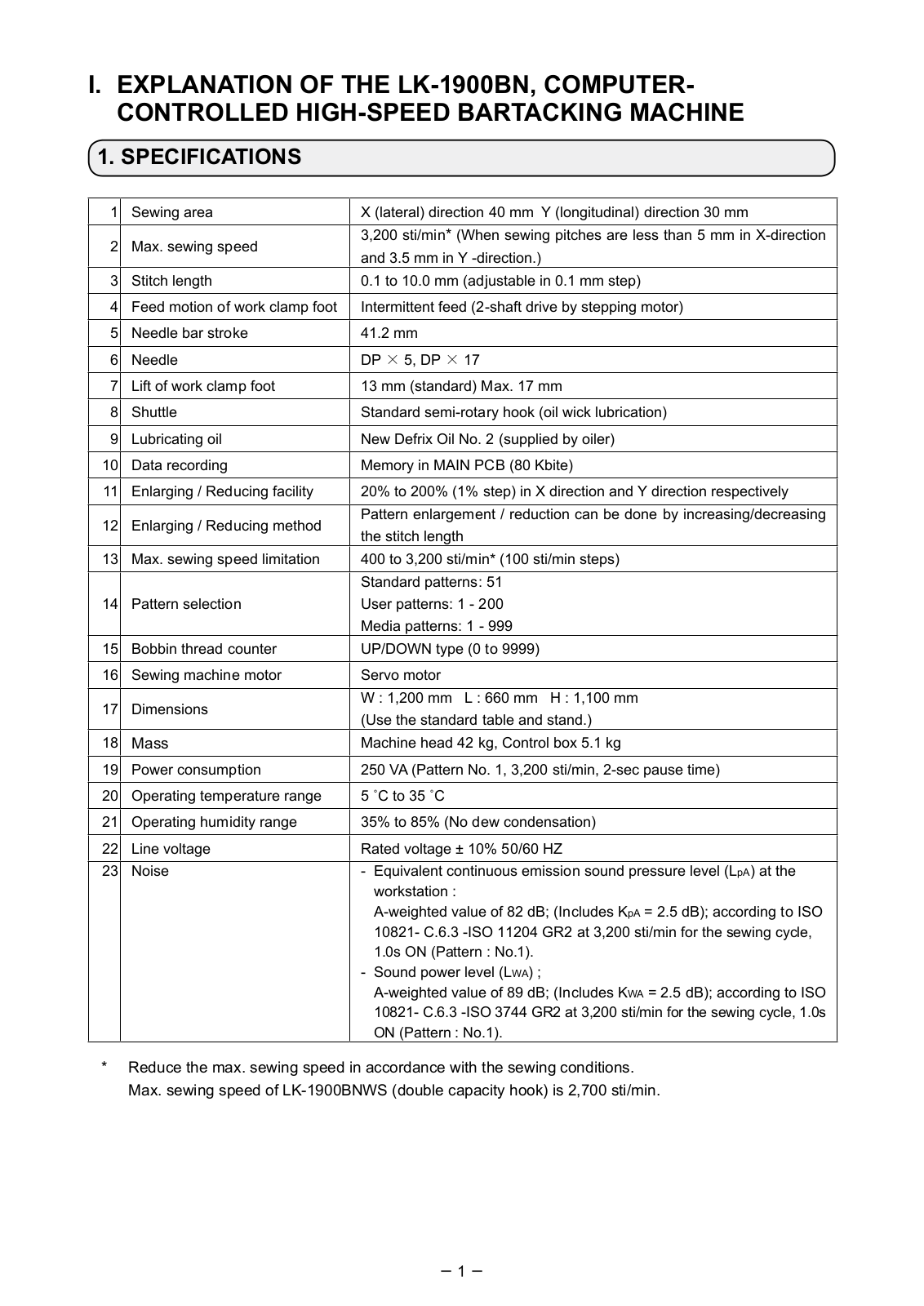
1 Sewing area X (lateral) direction 40 mm Y (longitudinal) direction 30 mm
2 Max. sewing speed 3,200 sti/min* (When sewing pitches are less than 5 mm in X-direction and 3.5 mm in Y -direction.)
3 Stitch length 0.1 to 10.0 mm (adjustable in 0.1 mm step)
4 Feed motion of work clamp foot Intermittent feed (2-shaft drive by stepping motor)
5 Needle bar stroke 41.2 mm
6 Needle DP 5, DP 17
7 Lift of work clamp foot 13 mm (standard) Max. 17 mm
8 Shuttle Standard semi-rotary hook (oil wick lubrication)
9 Lubricating oil New Defrix Oil No. 2 (supplied by oiler)
10 Data recording Memory in MAIN PCB (80 Kbite)
11 Enlarging / Reducing facility 20% to 200% (1% step) in X direction and Y direction respectively
12 Enlarging / Reducing method Pattern enlargement / reduction can be done by increasing/decreasing the stitch length
13 Max. sewing speed limitation 400 to 3,200 sti/min* (100 sti/min steps)
14 Pattern selection Standard patterns: 51 User patterns: 1 — 200 Media patterns: 1 — 999
15 Bobbin thread counter UP/DOWN type (0 to 9999)
16 Sewing machine motor Servo motor
17 Dimensions W : 1,200 mm L : 660 mm H : 1,100 mm (Use the standard table and stand.)
18 Mass Machine head 42 kg, Control box 5.1 kg
19 Power consumption 250 VA (Pattern No. 1, 3,200 sti/min, 2-sec pause time)
20 Operating temperature range 5 C to 35 C
21 Operating humidity range 35% to 85% (No dew condensation)
22 Line voltage Rated voltage 10% 50/60 HZ 23 Noise — Equivalent continuous emission sound pressure level (LpA) at the
workstation : A-weighted value of 82 dB; (Includes KpA = 2.5 dB); according to ISO
10821- C.6.3 -ISO 11204 GR2 at 3,200 sti/min for the sewing cycle, 1.0s ON (Pattern : No.1).
— Sound power level (LWA) ; A-weighted value of 89 dB; (Includes KWA = 2.5 dB); according to ISO
10821- C.6.3 -ISO 3744 GR2 at 3,200 sti/min for the sewing cycle, 1.0s ON (Pattern : No.1).
* Reduce the max. sewing speed in accordance with the sewing conditions. Max. sewing speed of LK-1900BNWS (double capacity hook) is 2,700 sti/min.
2
2. CONFIGURATION
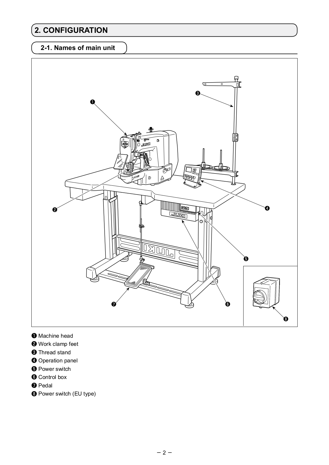
2-1. Names of main unit
Machine head Work clamp feet Thread stand Operation panel Power switch Control box Pedal Power switch (EU type)
3
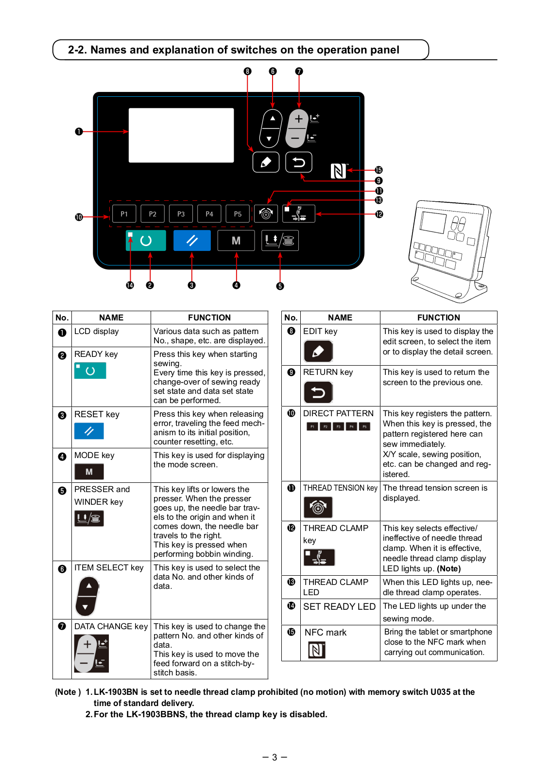
2-2. Names and explanation of switches on the operation panel
No. NAME FUNCTION
LCD display Various data such as pattern No., shape, etc. are displayed.
READY key Press this key when starting sewing. Every time this key is pressed, change-over of sewing ready set state and data set state can be performed.
RESET key Press this key when releasing error, traveling the feed mech- anism to its initial position, counter resetting, etc.
MODE key This key is used for displaying the mode screen.
PRESSER and WINDER key
This key lifts or lowers the presser. When the presser goes up, the needle bar trav- els to the origin and when it comes down, the needle bar travels to the right. This key is pressed when performing bobbin winding.
ITEM SELECT key This key is used to select the data No. and other kinds of data.
DATA CHANGE key This key is used to change the pattern No. and other kinds of data. This key is used to move the feed forward on a stitch-by- stitch basis.
No. NAME FUNCTION EDIT key This key is used to display the
edit screen, to select the item or to display the detail screen.
RETURN key This key is used to return the screen to the previous one.
DIRECT PATTERN This key registers the pattern. When this key is pressed, the pattern registered here can sew immediately. X/Y scale, sewing position, etc. can be changed and reg- istered.
THREAD TENSION key The thread tension screen is displayed.
THREAD CLAMP key
This key selects effective/ ineffective of needle thread clamp. When it is effective, needle thread clamp display LED lights up. (Note)
THREAD CLAMP LED
When this LED lights up, nee- dle thread clamp operates.
SET READY LED The LED lights up under the sewing mode.
NFC mark Bring the tablet or smartphone close to the NFC mark when carrying out communication.
(Note ) 1. LK-1903BN is set to needle thread clamp prohibited (no motion) with memory switch U035 at the time of standard delivery.
2. For the LK-1903BBNS, the thread clamp key is disabled.
4
3. INSTALLATION
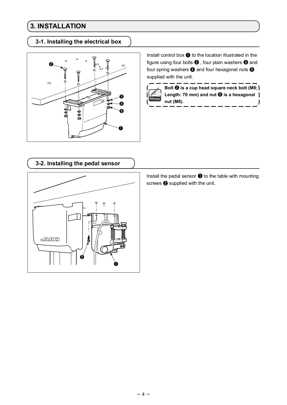
3-1. Installing the electrical box
Install control box to the location illustrated in the figure using four bolts , four plain washers and four spring washers and four hexagonal nuts supplied with the unit.
Bolt is a cup head square neck bolt (M8; Length: 70 mm) and nut is a hexagonal nut (M8).
Install the pedal sensor to the table with mounting screws supplied with the unit.
3-2. Installing the pedal sensor
5
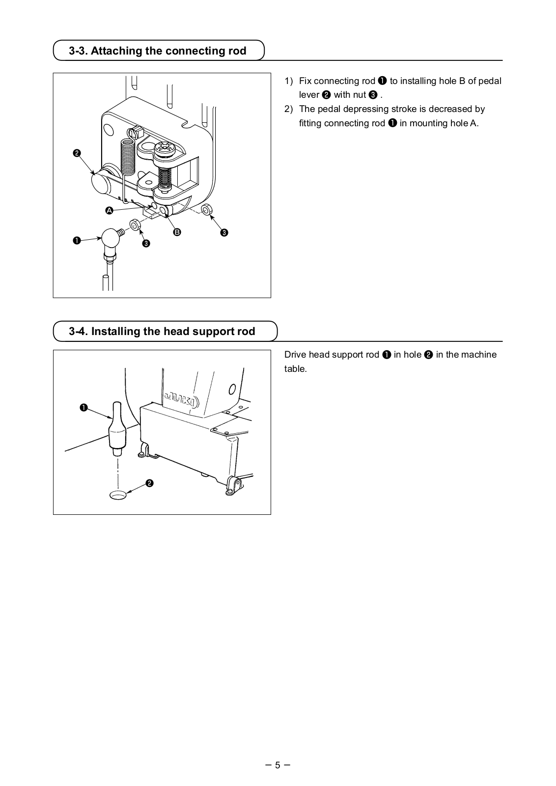
3-3. Attaching the connecting rod
3-4. Installing the head support rod
A
B
1) Fix connecting rod to installing hole B of pedal lever with nut .
2) The pedal depressing stroke is decreased by fitting connecting rod in mounting hole A.
Drive head support rod in hole in the machine table.
6
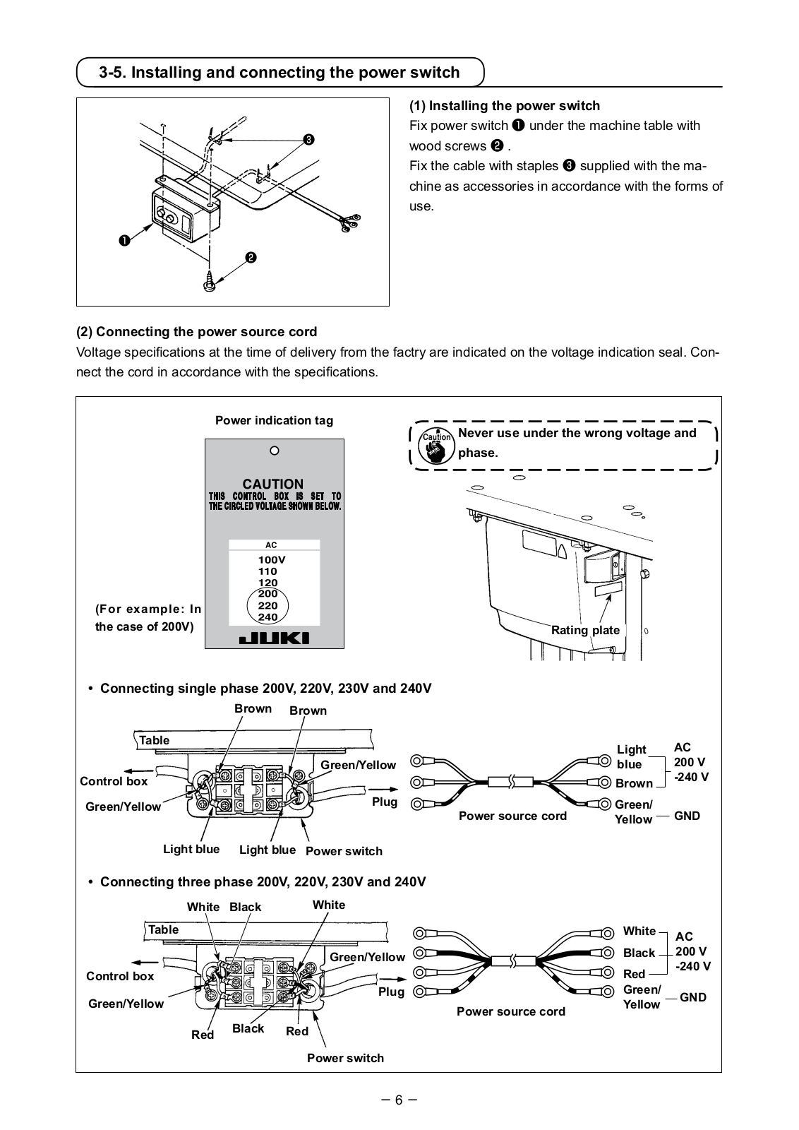
Never use under the wrong voltage and phase.
3-5. Installing and connecting the power switch
(2) Connecting the power source cord Voltage specifications at the time of delivery from the factry are indicated on the voltage indication seal. Con- nect the cord in accordance with the specifications.
Table
Brown Brown
Light blue Light blue
Light blue
Green/Yellow Green/ Yellow
Control box Green/Yellow
Plug Power source cord
Power switch
GND
AC 200 V -240 V
AC 200 V -240 V
Connecting single phase 200V, 220V, 230V and 240V
Table
RedBlack
Green/Yellow
White
Control box
Power source cord Plug
Power switch
GND
Connecting three phase 200V, 220V, 230V and 240V
Green/Yellow
Red
White
Black
Green/ Yellow
Red
White Black
Rating plate
Power indication tag
(For example: In the case of 200V)
Brown
(1) Installing the power switch Fix power switch under the machine table with wood screws . Fix the cable with staples supplied with the ma- chine as accessories in accordance with the forms of use.
7
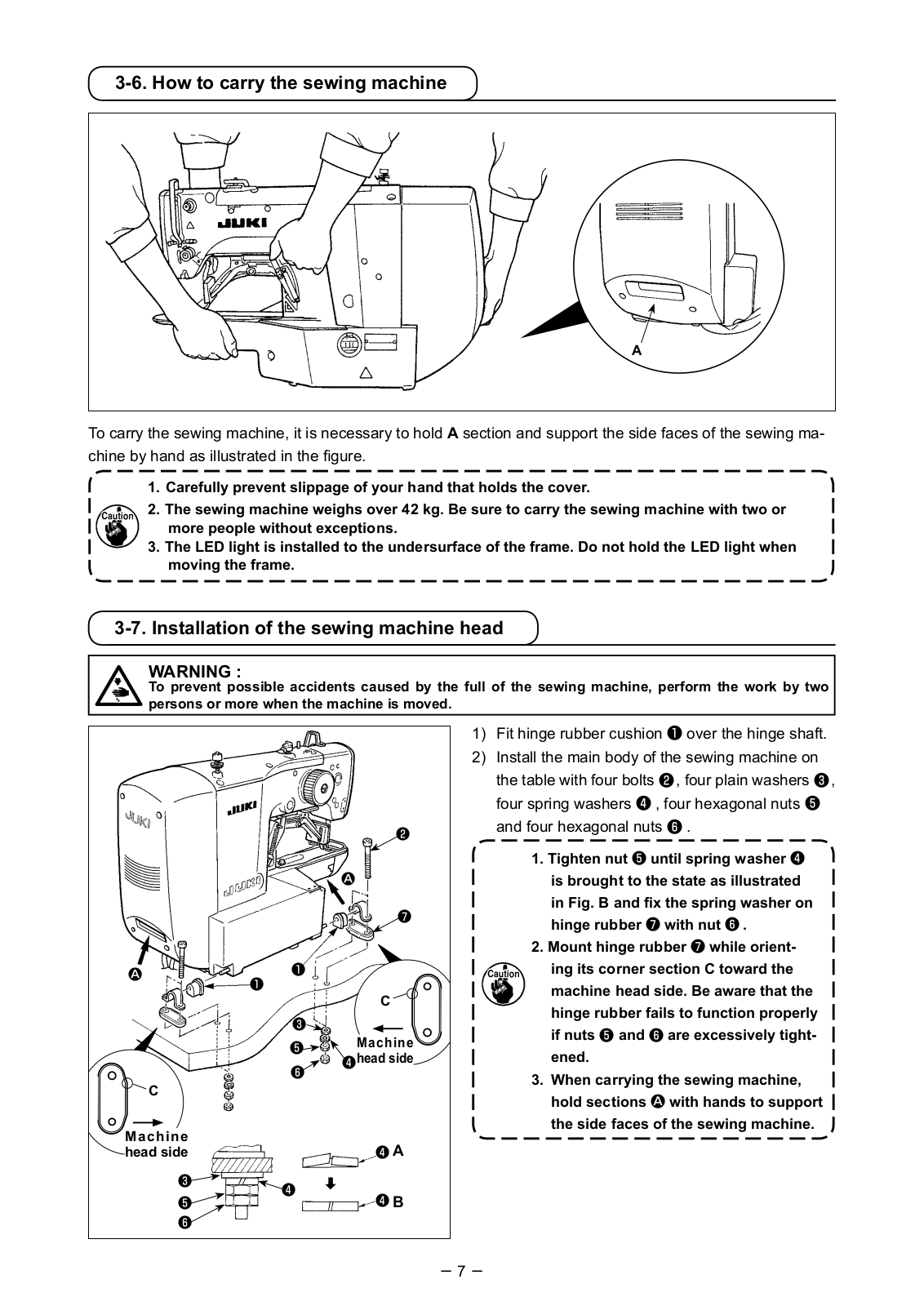
1) Fit hinge rubber cushion over the hinge shaft. 2) Install the main body of the sewing machine on
the table with four bolts , four plain washers , four spring washers , four hexagonal nuts and four hexagonal nuts .
1. Tighten nut until spring washer is brought to the state as illustrated in Fig. B and fix the spring washer on hinge rubber with nut .
2. Mount hinge rubber while orient- ing its corner section C toward the machine head side. Be aware that the hinge rubber fails to function properly if nuts and are excessively tight- ened.
3. When carrying the sewing machine, hold sections A with hands to support the side faces of the sewing machine.
3-7. Installation of the sewing machine head
WARNING : To prevent possible accidents caused by the full of the sewing machine, perform the work by two persons or more when the machine is moved.
A
3-6. How to carry the sewing machine
To carry the sewing machine, it is necessary to hold A section and support the side faces of the sewing ma- chine by hand as illustrated in the figure.
1. Carefully prevent slippage of your hand that holds the cover. 2. The sewing machine weighs over 42 kg. Be sure to carry the sewing machine with two or
more people without exceptions. 3. The LED light is installed to the undersurface of the frame. Do not hold the LED light when
moving the frame.
A
A
A
B
C
Machine head side
C
Machine head side
8
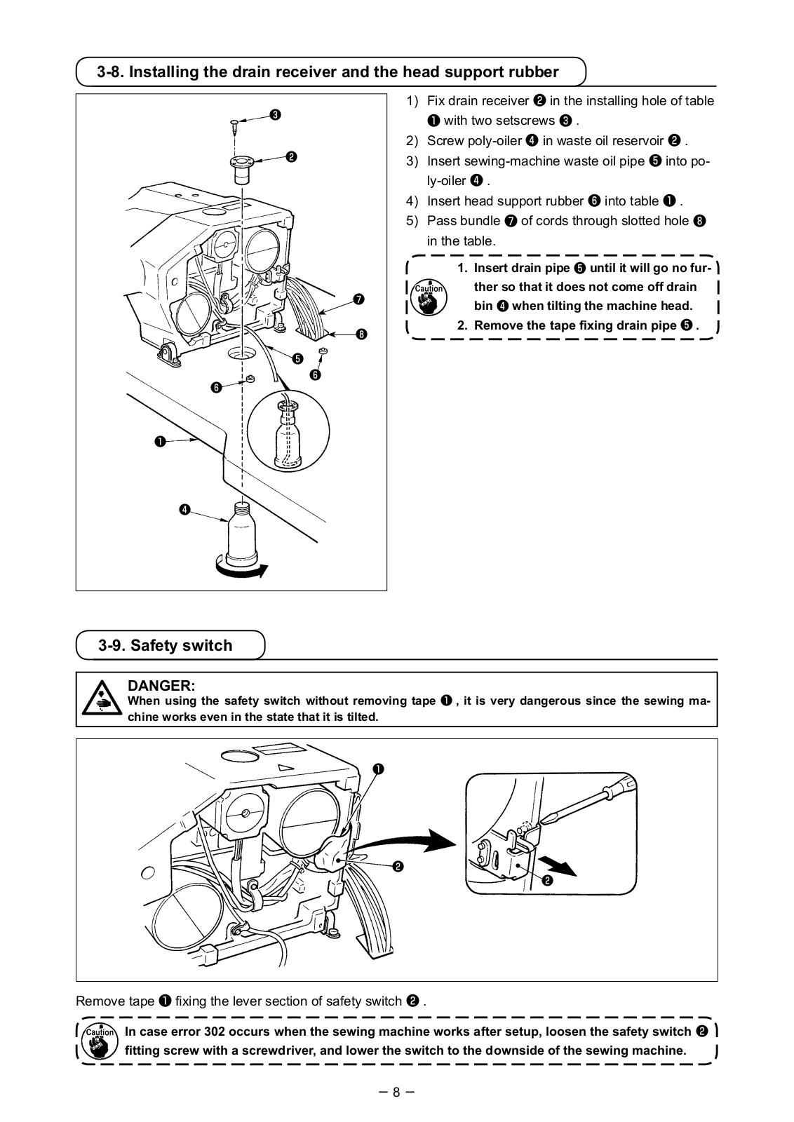
Remove tape fixing the lever section of safety switch .
In case error 302 occurs when the sewing machine works after setup, loosen the safety switch fitting screw with a screwdriver, and lower the switch to the downside of the sewing machine.
3-9. Safety switch
1) Fix drain receiver in the installing hole of table with two setscrews .
2) Screw poly-oiler in waste oil reservoir . 3) Insert sewing-machine waste oil pipe into po-
ly-oiler . 4) Insert head support rubber into table . 5) Pass bundle of cords through slotted hole
in the table.
1. Insert drain pipe until it will go no fur- ther so that it does not come off drain bin when tilting the machine head.
2. Remove the tape fixing drain pipe .
3-8. Installing the drain receiver and the head support rubber
DANGER: When using the safety switch without removing tape , it is very dangerous since the sewing ma- chine works even in the state that it is tilted.
9
3-11. Installing the operation panel
When tilting the sewing machine head, tilt the head gently until it comes in contact with head support rod .
1. Before tilting the sewing machine head, make sure that head support rod is attached to the machine table.
2. When raising the sewing machine head, do not raise it while holding motor cover . It will be the cause of breakage of motor cover .
3. Be sure to tilt the sewing machine head on a flat place to prevent it from falling.
3-10. Tilting the sewing machine head
WARNING : Tilt/raise the sewing machine head with both hands taking care not to allow your fingers to be caught in the head. Turn OFF the power before starting the work so as to prevent accidents caused by abrupt start of the sewing machine.
Fix operation panel mounting plate on the table with four wood screws . Then, pass the cable through hole in the table.
In the case of installing the operation panel on the undersurface of the table, install the operation panel on panel mounting plate by tightening screws in four mounting holes. Then, fix the panel mounting plate at a desired position on the undersurface of the table with four wood screws .
10
CN17
CN15
CN39
CN42
CN43
CN44
CN45
CN47
CN40
CN30
CN34
4P
9P
2P
6P
6P
4P
4P
2P
30P
26P
(LK-1901BN)
CN44 Black
SDC PWB
MAIN PWB
CN40 White
CN34 Gray
CN30 Gray
CN39 White
CN42 WhiteCN43 Blue
CN15 WhiteCN17 White
Shielded ground wire
A
3P
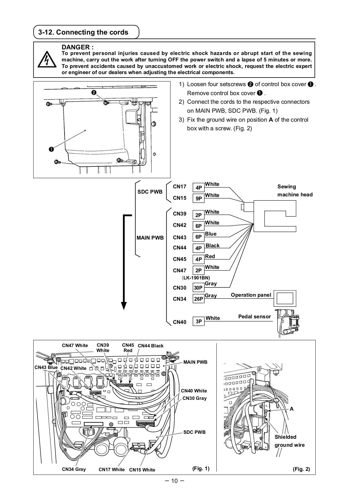
3-12. Connecting the cords
1) Loosen four setscrews of control box cover . Remove control box cover .
2) Connect the cords to the respective connectors on MAIN PWB, SDC PWB. (Fig. 1)
3) Fix the ground wire on position A of the control box with a screw. (Fig. 2)
DANGER : To prevent personal injuries caused by electric shock hazards or abrupt start of the sewing machine, carry out the work after turning OFF the power switch and a lapse of 5 minutes or more. To prevent accidents caused by unaccustomed work or electric shock, request the electric expert or engineer of our dealers when adjusting the electrical components.
SDC PWB
MAIN PWB
White
White
White
White
White
Gray
Gray
Blue
Black
Red
White
CN47 White
(Fig. 1) (Fig. 2)
Sewing machine head
Operation panel
Pedal sensor
CN45 Red
11
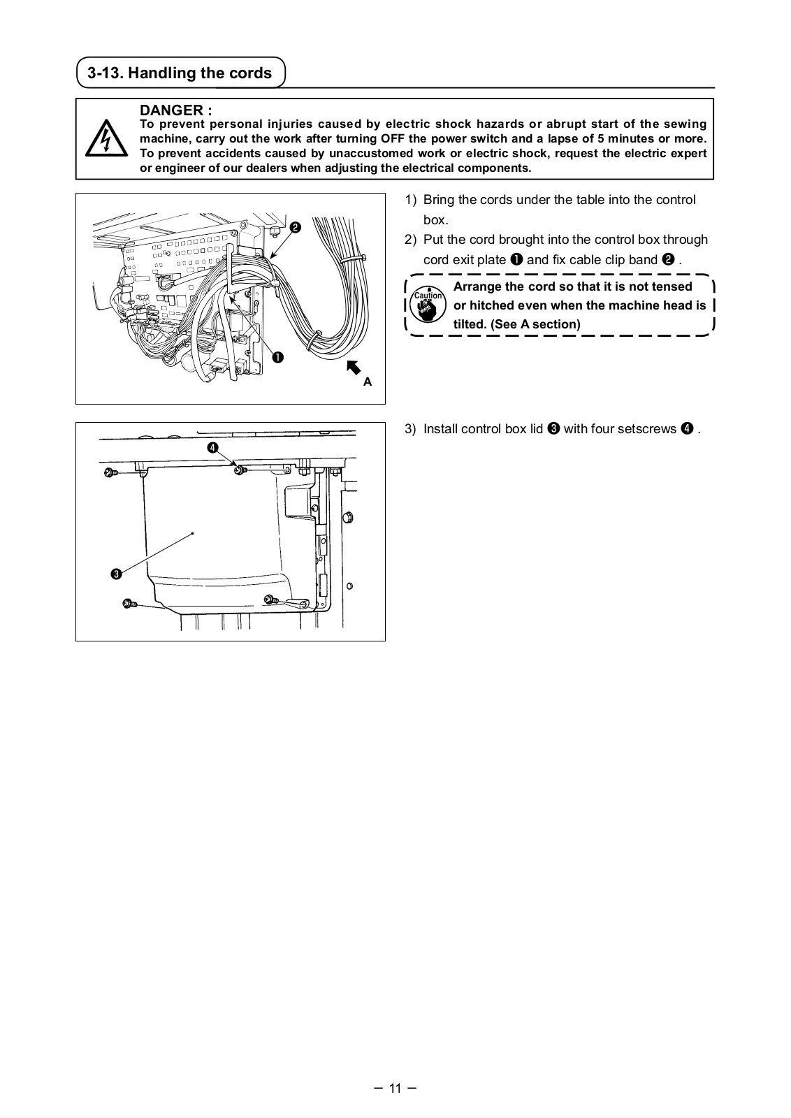
3-13. Handling the cords
1) Bring the cords under the table into the control box.
2) Put the cord brought into the control box through cord exit plate and fix cable clip band .
Arrange the cord so that it is not tensed or hitched even when the machine head is tilted. (See A section)
DANGER : To prevent personal injuries caused by electric shock hazards or abrupt start of the sewing machine, carry out the work after turning OFF the power switch and a lapse of 5 minutes or more. To prevent accidents caused by unaccustomed work or electric shock, request the electric expert or engineer of our dealers when adjusting the electrical components.
3) Install control box lid with four setscrews .
A
12
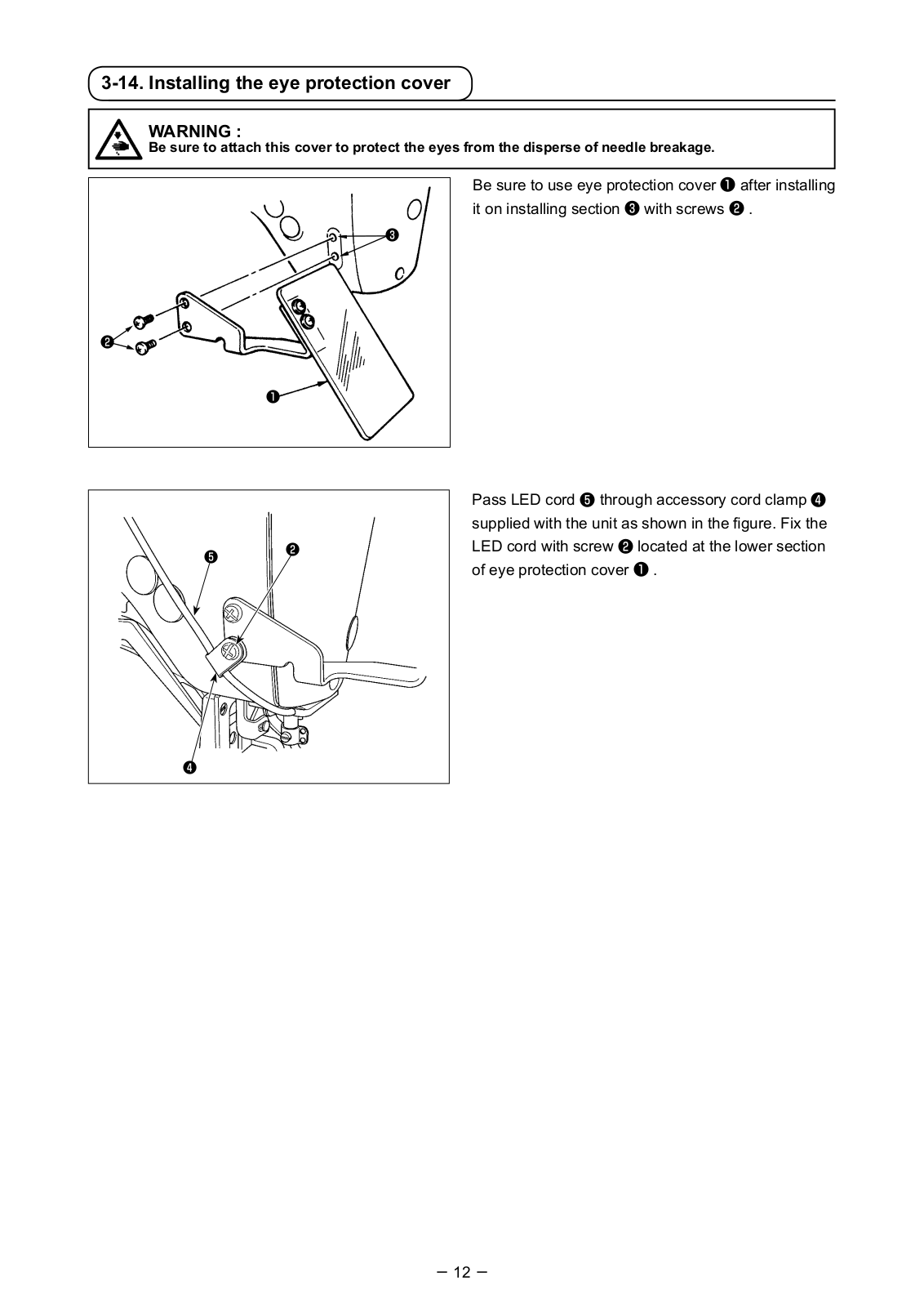
Be sure to use eye protection cover after installing it on installing section with screws .
3-14. Installing the eye protection cover
WARNING : Be sure to attach this cover to protect the eyes from the disperse of needle breakage.
Pass LED cord through accessory cord clamp supplied with the unit as shown in the figure. Fix the LED cord with screw located at the lower section of eye protection cover .
13
3-15. Installing the thread stand
1) Assemble the thread stand unit, and insert it in the hole in the machine table.
2) Tighten locknut to fix the thread stand. 3) For ceiling wiring, pass the power cord through
spool rest rod .
3-16. In the case the machine is transported after factory-completed at the time of shipment
Pass bed fixing bolt , plain washer and nut through hole in the table and hole in the sewing machine bed to fix the bed on the table.
14
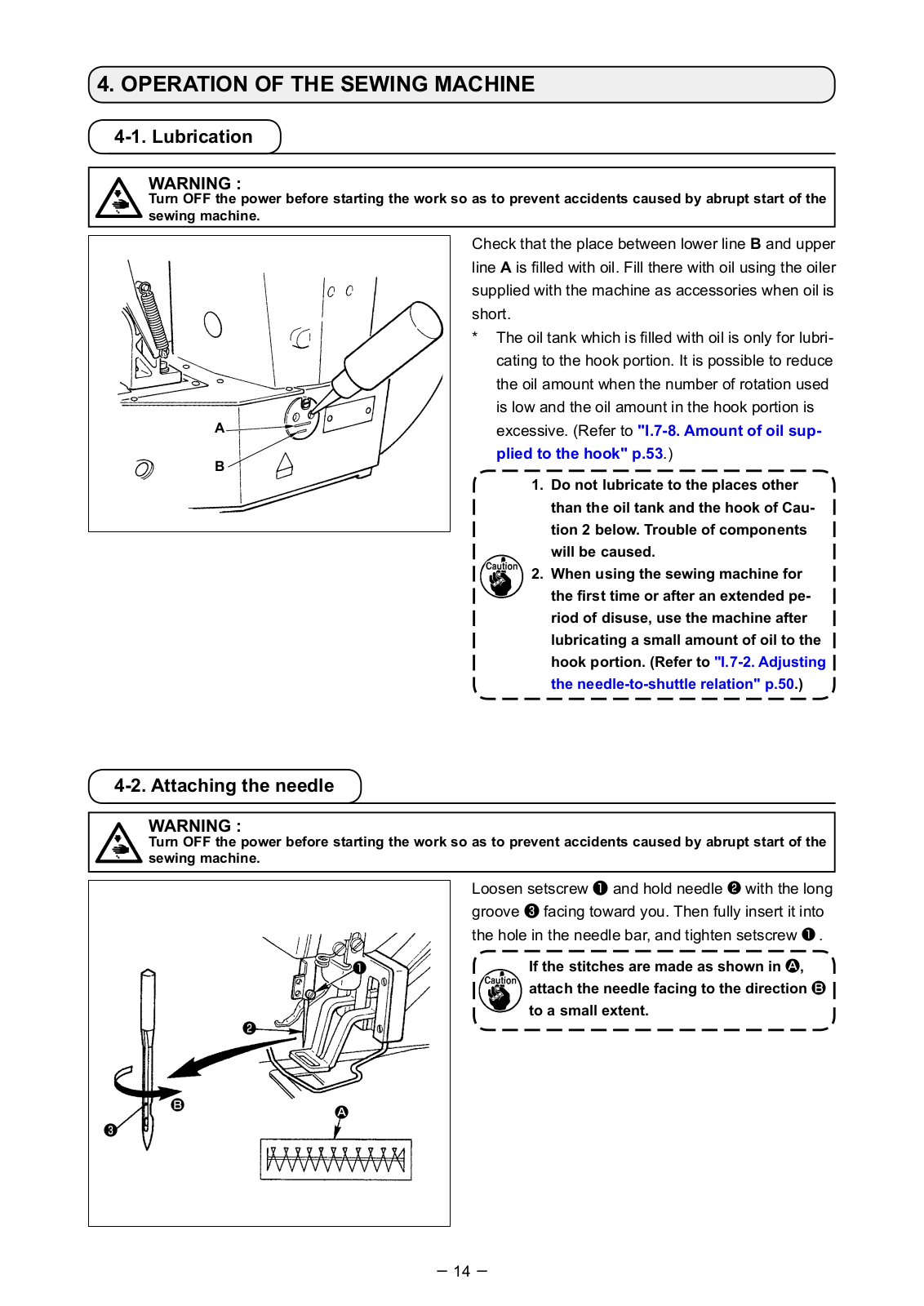
Check that the place between lower line B and upper line A is filled with oil. Fill there with oil using the oiler supplied with the machine as accessories when oil is short. * The oil tank which is filled with oil is only for lubri-
cating to the hook portion. It is possible to reduce the oil amount when the number of rotation used is low and the oil amount in the hook portion is excessive. (Refer to «I.7-8. Amount of oil sup- plied to the hook» p.53.)
1. Do not lubricate to the places other than the oil tank and the hook of Cau- tion 2 below. Trouble of components will be caused.
2. When using the sewing machine for the first time or after an extended pe- riod of disuse, use the machine after lubricating a small amount of oil to the hook portion. (Refer to «I.7-2. Adjusting the needle-to-shuttle relation» p.50.)
Loosen setscrew and hold needle with the long groove facing toward you. Then fully insert it into the hole in the needle bar, and tighten setscrew .
If the stitches are made as shown in A, attach the needle facing to the direction B to a small extent.
4. OPERATION OF THE SEWING MACHINE
4-1. Lubrication
4-2. Attaching the needle
AB
WARNING : Turn OFF the power before starting the work so as to prevent accidents caused by abrupt start of the sewing machine.
WARNING : Turn OFF the power before starting the work so as to prevent accidents caused by abrupt start of the sewing machine.
A
B
15
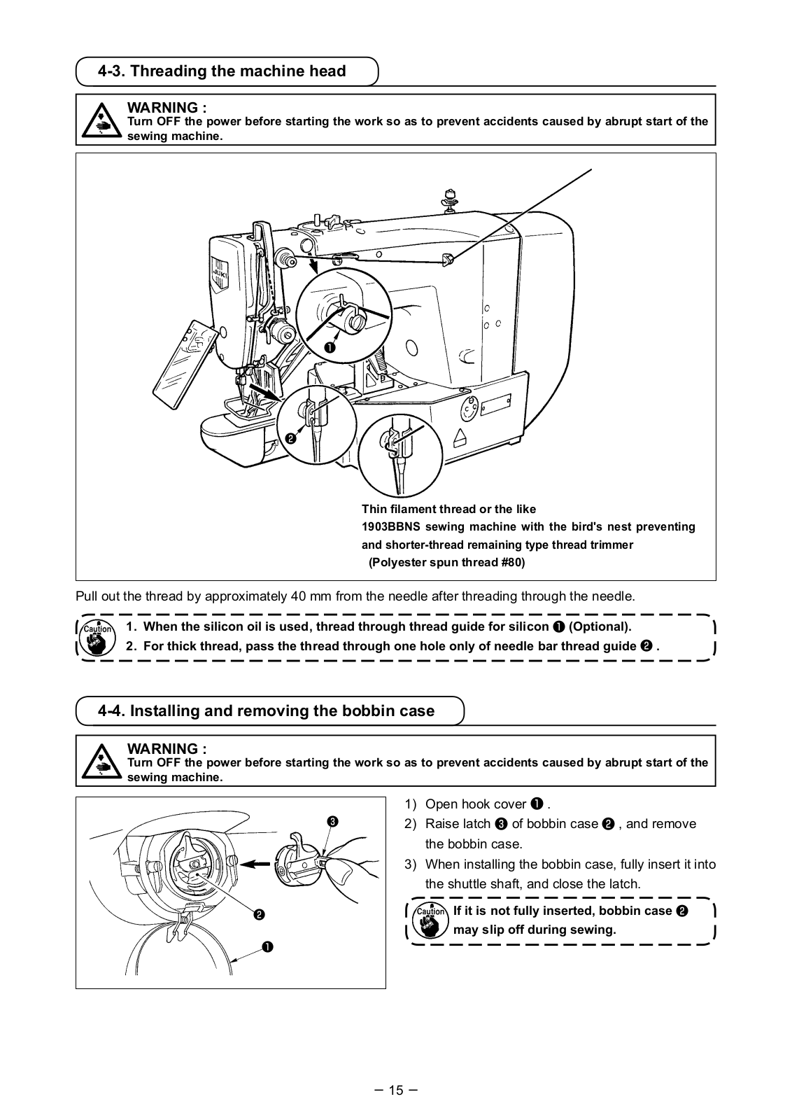
1) Open hook cover . 2) Raise latch of bobbin case , and remove
the bobbin case. 3) When installing the bobbin case, fully insert it into
the shuttle shaft, and close the latch.
If it is not fully inserted, bobbin case may slip off during sewing.
4-3. Threading the machine head
Pull out the thread by approximately 40 mm from the needle after threading through the needle.
1. When the silicon oil is used, thread through thread guide for silicon (Optional). 2. For thick thread, pass the thread through one hole only of needle bar thread guide .
4-4. Installing and removing the bobbin case
WARNING : Turn OFF the power before starting the work so as to prevent accidents caused by abrupt start of the sewing machine.
WARNING : Turn OFF the power before starting the work so as to prevent accidents caused by abrupt start of the sewing machine.
Thin filament thread or the like 1903BBNS sewing machine with the bird’s nest preventing and shorter-thread remaining type thread trimmer (Polyester spun thread #80)
16
Adjusting the needle thread tension
4-6. Adjusting the thread tension
Short
Long
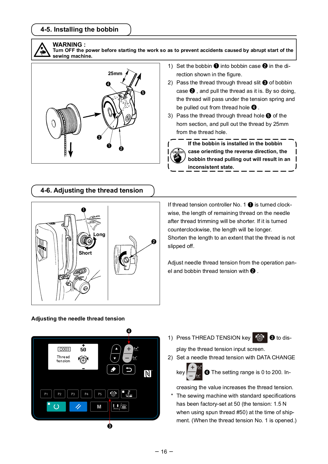
1) Set the bobbin into bobbin case in the di- rection shown in the figure.
2) Pass the thread through thread slit of bobbin case , and pull the thread as it is. By so doing, the thread will pass under the tension spring and be pulled out from thread hole .
3) Pass the thread through thread hole of the horn section, and pull out the thread by 25mm from the thread hole.
If the bobbin is installed in the bobbin case orienting the reverse direction, the bobbin thread pulling out will result in an inconsistent state.
4-5. Installing the bobbin
25mm
WARNING : Turn OFF the power before starting the work so as to prevent accidents caused by abrupt start of the sewing machine.
1) Press THREAD TENSION key to dis-
play the thread tension input screen. 2) Set a needle thread tension with DATA CHANGE
key The setting range is 0 to 200. In-
creasing the value increases the thread tension. * The sewing machine with standard specifications
has been factory-set at 50 (the tension: 1.5 N when using spun thread #50) at the time of ship- ment. (When the thread tension No. 1 is opened.)
If thread tension controller No. 1 is turned clock- wise, the length of remaining thread on the needle after thread trimming will be shorter. If it is turned counterclockwise, the length will be longer. Shorten the length to an extent that the thread is not slipped off.
Adjust needle thread tension from the operation pan- el and bobbin thread tension with .
17
4-7. Adjusting the thread take-up spring
4-8. Example of the thread tension
When using the sewing machine for the first time, adjust the thread tension referring to the table below.
Thread
Polyester filament thread #50 Polyester spun thread #50 Polyester spun thread #60 (Thread clamp OFF) Cotton thread #50 Cotton thread #20
Material
Wool Wool
T/C broad
Denim Denim
Needle thread tension setting
30 to 35 50 to 55 30 to 35
35 to 45 35 to 45
Thread take-up spring moving amount [Thread drawing amount]
10mm [13mm] 10mm [13mm]
8 to 10mm [11 to 13mm]
10mm [13mm] 8 to 10mm [11 to 13mm]
Strength
0.1N 0.2N 0.1N
0.1N 0.1N
5-1. Selection of language
When you turn ON the power to the sewing machine for the first time after the purchase, the language selection screen is displayed. Select the language to
be displayed, then press RETURN key .
The language to be displayed on the screen can be changed by means of the memory switch U239 «Language selection». Refer to «I.8. HOW TO USE THE MEMORY SWITCH» p.56 for the details of the memory switch.
If you terminate the language selection by
pressing RETURN key without se-
lecting the language, the language selection screen will be displayed every time you turn ON the power to the sewing machine.
5. OPERATION OF THE SEWING MACHINE (BASIC) Set each item following the procedure described below.
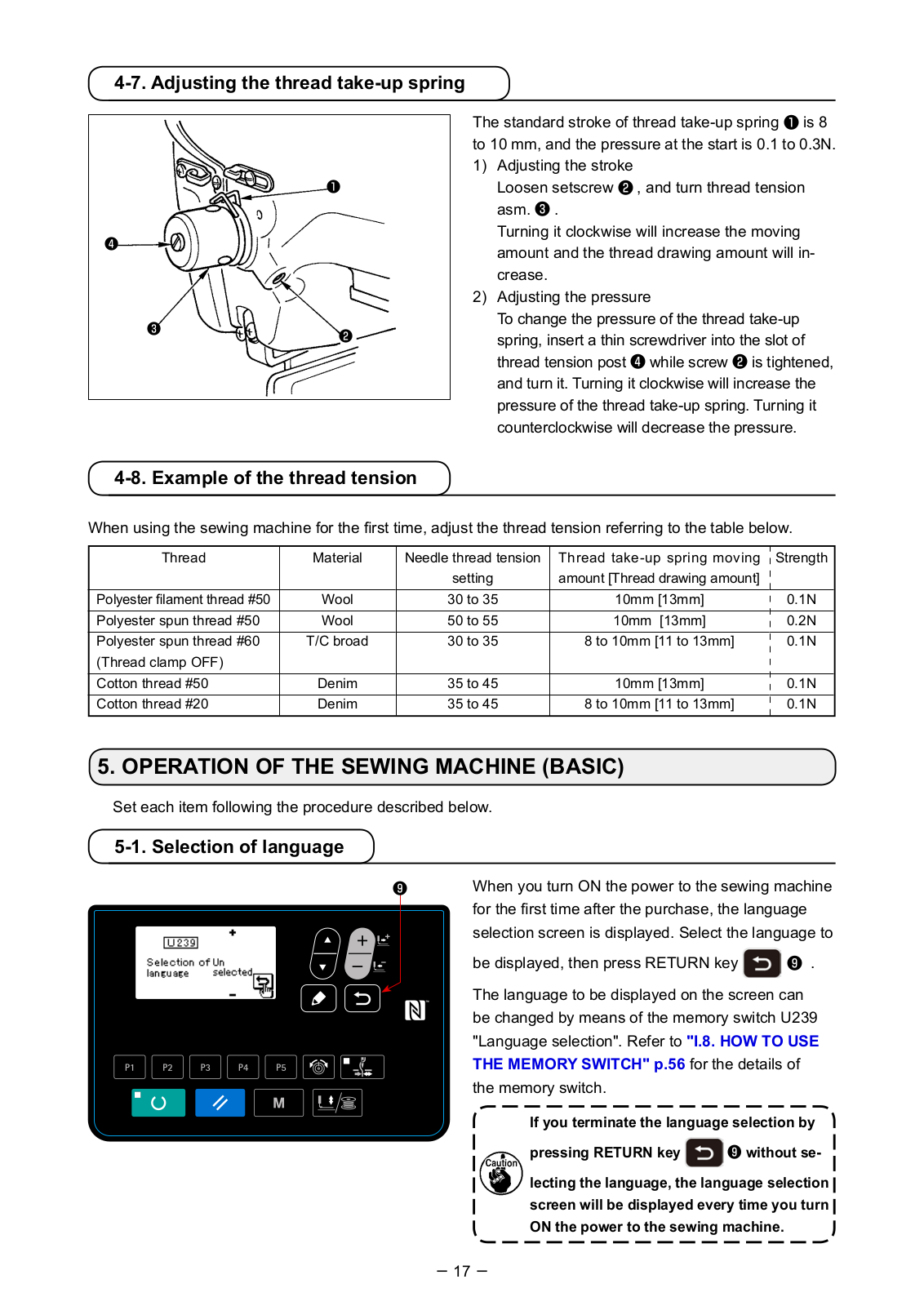
The standard stroke of thread take-up spring is 8 to 10 mm, and the pressure at the start is 0.1 to 0.3N. 1) Adjusting the stroke Loosen setscrew , and turn thread tension
asm. . Turning it clockwise will increase the moving
amount and the thread drawing amount will in- crease.
2) Adjusting the pressure To change the pressure of the thread take-up
spring, insert a thin screwdriver into the slot of thread tension post while screw is tightened, and turn it. Turning it clockwise will increase the pressure of the thread take-up spring. Turning it counterclockwise will decrease the pressure.
18
The setting exceeding 100% is dangerous since needle and the cloth presser inter- feres with each other and needle breakage or the like will occur.
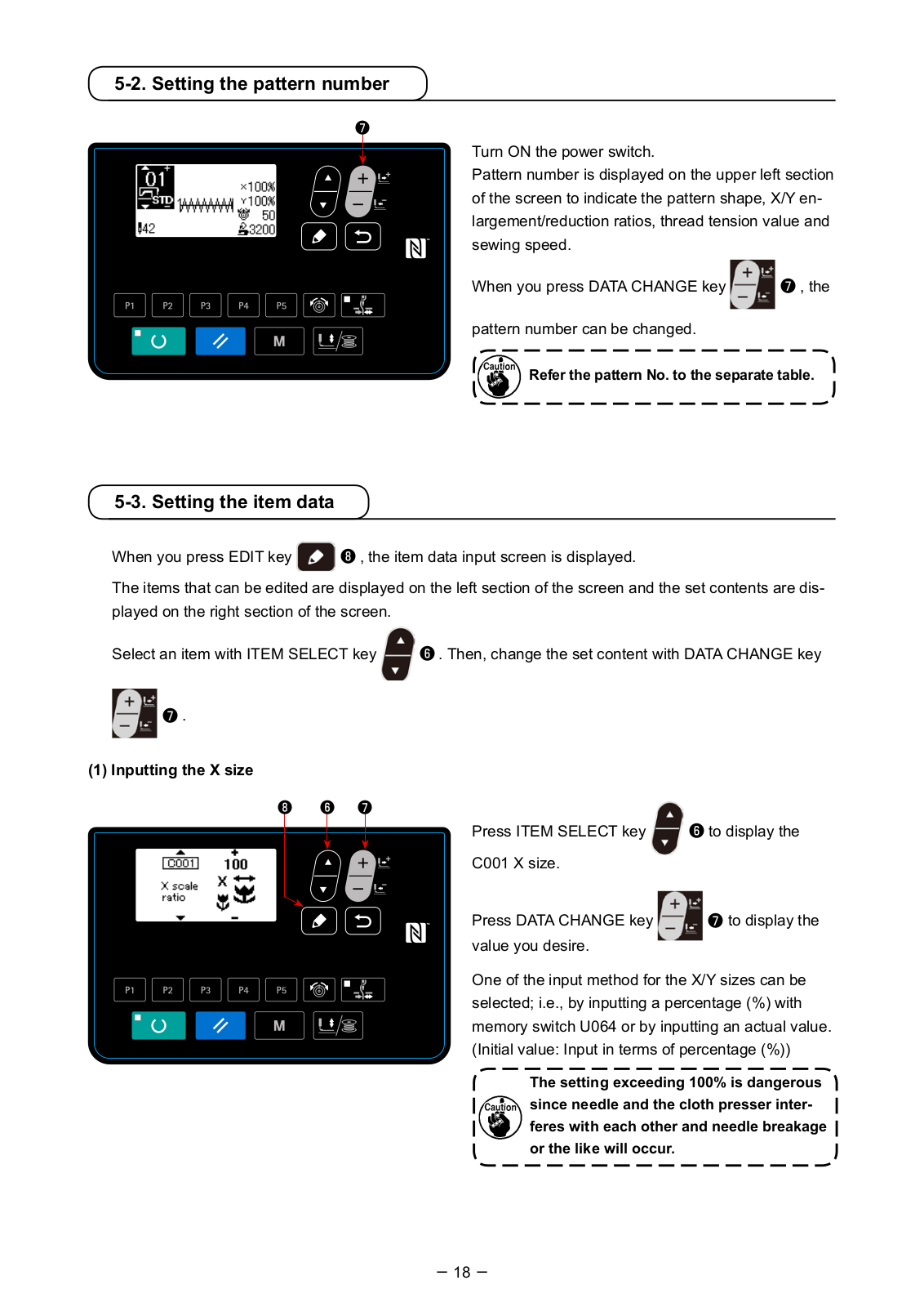
Turn ON the power switch. Pattern number is displayed on the upper left section of the screen to indicate the pattern shape, X/Y en- largement/reduction ratios, thread tension value and sewing speed.
When you press DATA CHANGE key , the
pattern number can be changed.
Refer the pattern No. to the separate table.
5-3. Setting the item data
When you press EDIT key , the item data input screen is displayed.
The items that can be edited are displayed on the left section of the screen and the set contents are dis- played on the right section of the screen.
Select an item with ITEM SELECT key . Then, change the set content with DATA CHANGE key
.
(1) Inputting the X size
Press ITEM SELECT key to display the
C001 X size.
Press DATA CHANGE key to display the value you desire.
One of the input method for the X/Y sizes can be selected; i.e., by inputting a percentage (%) with memory switch U064 or by inputting an actual value. (Initial value: Input in terms of percentage (%))
5-2. Setting the pattern number
19
(2) Inputting the Y size
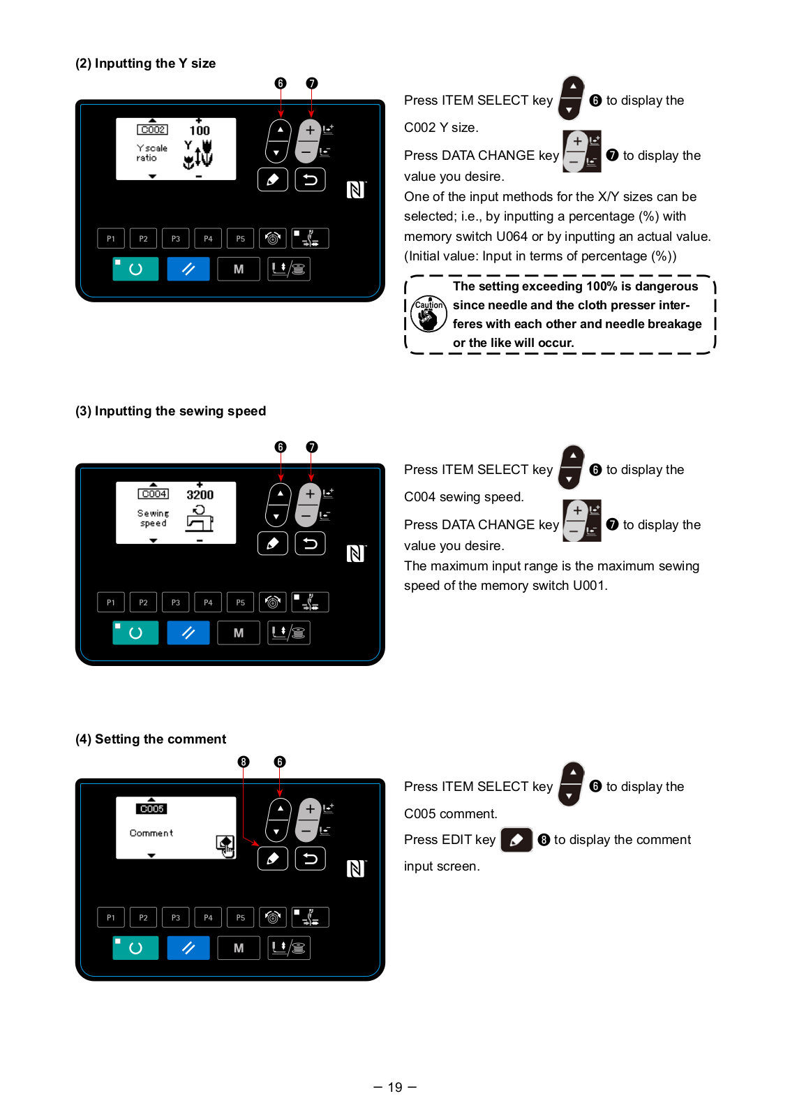
The setting exceeding 100% is dangerous since needle and the cloth presser inter- feres with each other and needle breakage or the like will occur.
Press ITEM SELECT key to display the
C002 Y size.
Press DATA CHANGE key to display the value you desire. One of the input methods for the X/Y sizes can be selected; i.e., by inputting a percentage (%) with memory switch U064 or by inputting an actual value. (Initial value: Input in terms of percentage (%))
(3) Inputting the sewing speed
Press ITEM SELECT key to display the
C004 sewing speed.
Press DATA CHANGE key to display the value you desire. The maximum input range is the maximum sewing speed of the memory switch U001.
(4) Setting the comment
Press ITEM SELECT key to display the
C005 comment.
Press EDIT key to display the comment
input screen.
20
On the comment input screen, as many as 14 char- acters can be input. The characters that can be input are alphabets, numbers and symbols.
Press ITEM SELECT key to specify the
input position. Press DATA CHANGE key to select the characters to be entered.
When you press RESET key , the charac-
ter at the current input position is erased. When you
keep RESET key held pressed, all charac-
ters which have been input are erased.
(5) Setting the thread tension
Press THREAD TENSION key to display
the C003 thread tension.
Press DATA CHANGE key to display the
value you desire. (Input range: 0 — 200) After setting the sewing data, press RETURN key
to return to the input screen.
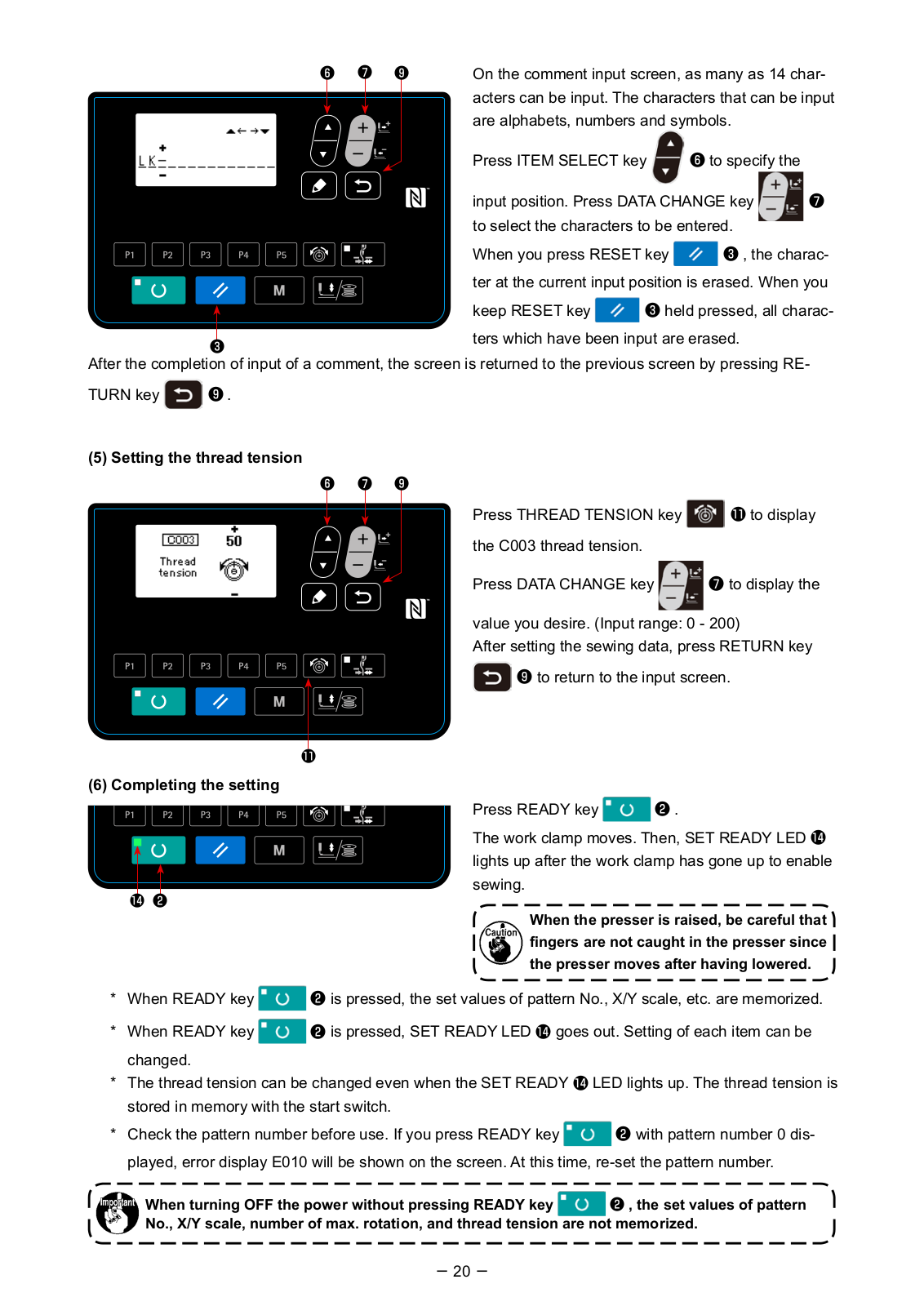
(6) Completing the setting Press READY key .
The work clamp moves. Then, SET READY LED lights up after the work clamp has gone up to enable sewing.
When the presser is raised, be careful that fingers are not caught in the presser since the presser moves after having lowered.
* When READY key is pressed, the set values of pattern No., X/Y scale, etc. are memorized.
* When READY key is pressed, SET READY LED goes out. Setting of each item can be
changed. * The thread tension can be changed even when the SET READY LED lights up. The thread tension is
stored in memory with the start switch.
* Check the pattern number before use. If you press READY key with pattern number 0 dis-
played, error display E010 will be shown on the screen. At this time, re-set the pattern number.
When turning OFF the power without pressing READY key , the set values of pattern No., X/Y scale, number of max. rotation, and thread tension are not memorized.
After the completion of input of a comment, the screen is returned to the previous screen by pressing RE-
TURN key .
21
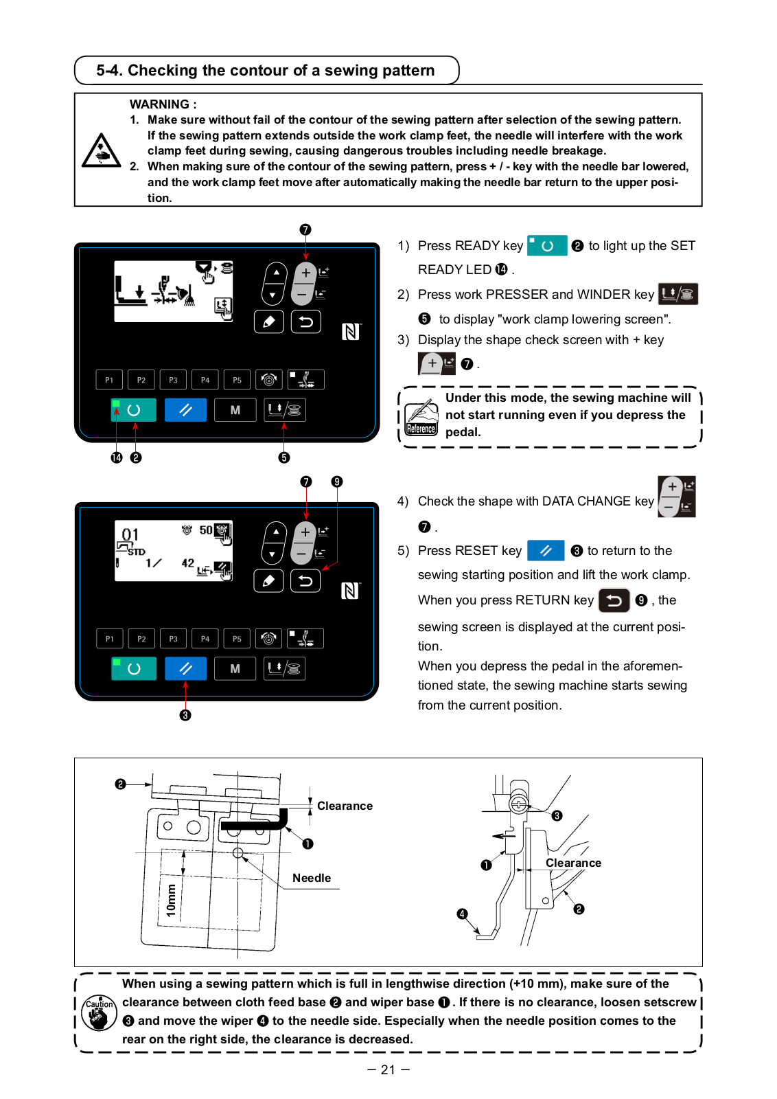
When using a sewing pattern which is full in lengthwise direction (+10 mm), make sure of the clearance between cloth feed base and wiper base . If there is no clearance, loosen setscrew and move the wiper to the needle side. Especially when the needle position comes to the rear on the right side, the clearance is decreased.
5-4. Checking the contour of a sewing pattern
Under this mode, the sewing machine will not start running even if you depress the pedal.
WARNING : 1. Make sure without fail of the contour of the sewing pattern after selection of the sewing pattern.
If the sewing pattern extends outside the work clamp feet, the needle will interfere with the work clamp feet during sewing, causing dangerous troubles including needle breakage.
2. When making sure of the contour of the sewing pattern, press + / — key with the needle bar lowered, and the work clamp feet move after automatically making the needle bar return to the upper posi- tion.
Needle
10 m
m
Clearance
Clearance
1) Press READY key to light up the SET
READY LED .
2) Press work PRESSER and WINDER key
to display «work clamp lowering screen». 3) Display the shape check screen with + key
.
4) Check the shape with DATA CHANGE key
.
5) Press RESET key to return to the
sewing starting position and lift the work clamp.
When you press RETURN key , the
sewing screen is displayed at the current posi- tion.
When you depress the pedal in the aforemen- tioned state, the sewing machine starts sewing from the current position.
22
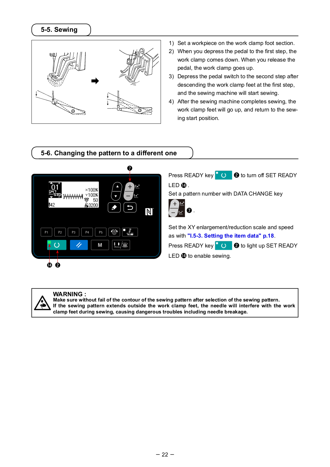
5-5. Sewing
WARNING : Make sure without fail of the contour of the sewing pattern after selection of the sewing pattern. If the sewing pattern extends outside the work clamp feet, the needle will interfere with the work clamp feet during sewing, causing dangerous troubles including needle breakage.
5-6. Changing the pattern to a different one
Press READY key to turn off SET READY
LED . Set a pattern number with DATA CHANGE key
.
Set the XY enlargement/reduction scale and speed as with «I.5-3. Setting the item data» p.18.
Press READY key to light up SET READY
LED to enable sewing.
1) Set a workpiece on the work clamp foot section. 2) When you depress the pedal to the first step, the
work clamp comes down. When you release the pedal, the work clamp goes up.
3) Depress the pedal switch to the second step after descending the work clamp feet at the first step, and the sewing machine will start sewing.
4) After the sewing machine completes sewing, the work clamp feet will go up, and return to the sew- ing start position.
23
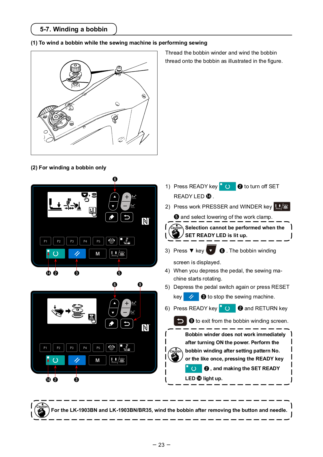
5-7. Winding a bobbin
(1) To wind a bobbin while the sewing machine is performing sewing
Selection cannot be performed when the SET READY LED is lit up.
Thread the bobbin winder and wind the bobbin thread onto the bobbin as illustrated in the figure.
(2) For winding a bobbin only
Bobbin winder does not work immediately after turning ON the power. Perform the bobbin winding after setting pattern No. or the like once, pressing the READY key
, and making the SET READY
LED light up.
1) Press READY key to turn off SET
READY LED .
2) Press work PRESSER and WINDER key
and select lowering of the work clamp.
3) Press key . The bobbin winding
screen is displayed. 4) When you depress the pedal, the sewing ma-
chine starts rotating. 5) Depress the pedal switch again or press RESET
key to stop the sewing machine.
6) Press READY key and RETURN key
to exit from the bobbin winding screen.
For the LK-1903BN and LK-1903BN/BR35, wind the bobbin after removing the button and needle.
24
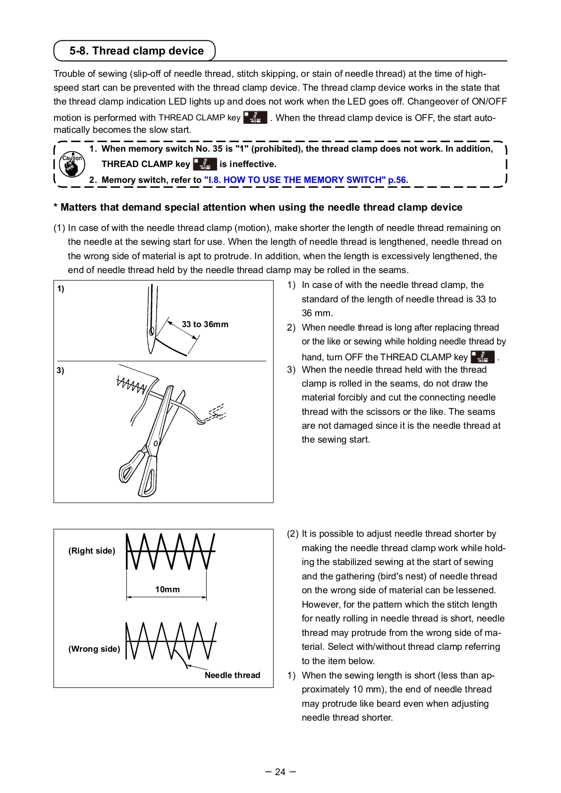
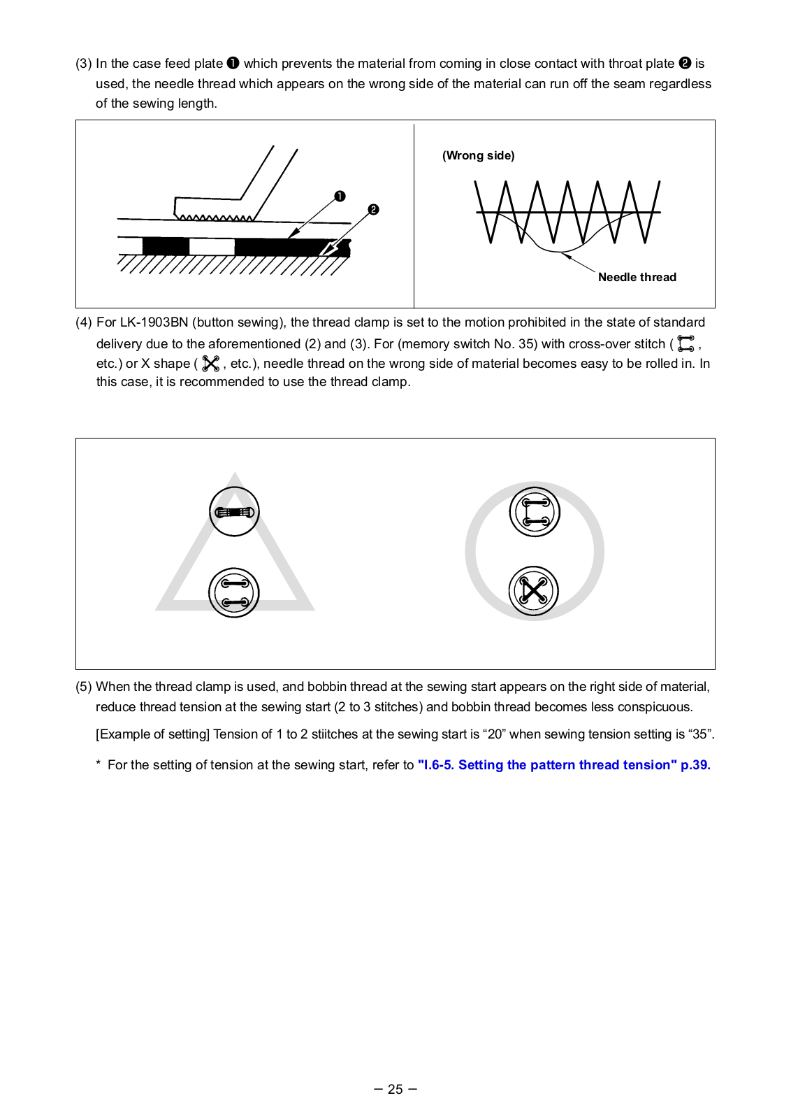
5-8. Thread clamp device
Trouble of sewing (slip-off of needle thread, stitch skipping, or stain of needle thread) at the time of high- speed start can be prevented with the thread clamp device. The thread clamp devic
FAQ: Types of Manuals and Their Contents
JUKI LK-1900BN Manuals come in various types, each serving a specific purpose to help users effectively operate and maintain their devices. Here are the common types of JUKI LK-1900BN User Guides and the information they typically include:
- User Manuals: Provide comprehensive instructions on how to use the device, including setup, features, and operation. They often include troubleshooting tips, safety information, and maintenance guidelines.
- Service Instructions: Designed for technicians and repair professionals, these manuals offer detailed information on diagnosing and repairing issues with the device. They include schematics, parts lists, and step-by-step repair procedures.
- Installation Guides: Focus on the installation process of the device, providing detailed instructions and diagrams for proper setup. They are essential for ensuring the device is installed correctly and safely.
- Maintenance Manuals: Provide guidance on routine maintenance tasks to keep the device in optimal condition. They cover cleaning procedures, part replacements, and regular servicing tips.
- Quick Start Guides: Offer a concise overview of the essential steps needed to get the device up and running quickly. They are ideal for users who need immediate assistance with basic setup and operation.
Each type of JUKI LK-1900BN instruction is designed to address specific needs, ensuring users have the necessary information to use, maintain, and repair their devices effectively.
Related Instructions for JUKI LK-1900BN:
1
DDL-900A
Instruction manual JUKI Sewing Machine Instruction manual (File: juki-ddl-900a-instruction-manual-52, Tue 02.2025)
52
217
33
3
IP-200
Setup manual JUKI IP-200 User Manual (Setup manual), @AJ464J
25
368
78
5
MO-804
Instruction book User Manual: JUKI MO-804 (QIJH41, Upd.Thursday 27-02-2025)
16
157
38
7
MOL-254
Manual JUKI MOL-254 Manual (Manual ), @75Y765
179
1096
253
8
HZL-E70
Service manual #J73M61: HZL-E70 Sewing Machine Service manual
24
1370
302
Sewing Machine Devices by Other Brands:
|
JUKI NA-35UT Instruction Manual And Spare Parts List JUKI NA-35UT Guide (Instruction manual and spare parts list), @VKXVGV � ru: .$ I .illlrii�JJ fJt 13 May 2025 | 76 |
|
|
Kenmore 385.18330 Owner’s Manual Sewing Machine #U354D3 S_FA/RtSOwner’s 21 May 2025 | 114 |
|
|
JUKI LK-1910 Engineer’s Manual Sewing Machine #8938Y3 29326600 13 Jan 2025 | 187 |
|
|
Brother PR-620 Tips And Techniques PDF User Guide (@11MMHN), Brother PR-620 Sewing Machine (04th Mar 2025) Tips and Techniques on the PR-620 04 Mar 2025 | 15 |
Categories:
Industrial Equipment
Kitchen Appliances
Indoor Furnishing
Touch terminals
Sewing Machine Accessories
Printer
Инструкция
Посмотреть инструкция для Juki LK-1900BN бесплатно. Руководство относится к категории швейные машины, 2 человек(а) дали ему среднюю оценку 8. Руководство доступно на следующих языках: русский. У вас есть вопрос о Juki LK-1900BN или вам нужна помощь?
Задайте свой вопрос здесь
Ниже вы найдете технические характеристики изделия и руководства по эксплуатации Juki LK-1900BN.
Juki LK-1900BN является швейной машиной, предназначенной для индустриального использования. Он обеспечивает быструю и точную работу с тканями различной плотности и состава. Машина оснащена одноведущим устройством, которое обеспечивает прямолинейное и равномерное движение ткани во время шитья.
Juki LK-1900BN оснащена функцией автоматического обрезания нити, что снижает время и усилия при работе с большим объемом швейных изделий. Она также может работать с широким спектром нитей, включая нитки разной толщины и состава.
Машина имеет регулируемую скорость шитья, что позволяет пользователю выбрать оптимальную скорость в зависимости от типа ткани и характера работы. Встроенный контроллер обеспечивает простоту и удобство настройки параметров шитья.
Juki LK-1900BN имеет прочную конструкцию и надежность. Его стабильная рама и прочные детали обеспечивают долговечность при интенсивном использовании. Машина также обладает надежностью в работе, что позволяет ей эффективно работать в течение длительного времени без сбоев.
Количество указанных функций и характеристик может варьироваться в зависимости от конкретной модели Juki LK-1900BN. Рекомендуется проверить дополнительные спецификации у производителя или уточнить у продавца.
Главная
| Бренд | Juki |
| Модель | LK-1900BN |
| Изделие | швейная машина |
| Язык | русский |
| Тип файла | Руководство пользователя (PDF) |
Часто задаваемые вопросы
Не можете найти ответ на свой вопрос в руководстве? Вы можете найти ответ на свой вопрос ниже, в разделе часто задаваемых вопросов о Juki LK-1900BN.
Какой размер иглы лучше всего использовать?
Наиболее подходящий размер иглы зависит от используемой толщины ткани. С плотной тканью следует использовать толстую иглу. Подходящие типы тканей указываются на упаковке с иглами.
Что может повредить иглу при шитье?
Причин повреждения иглы может быть несколько:
— Использование неподходящей иглы для определенного типа ткани
— Установка иглы слишком низко
— Неправильное расположение ткани
— Неправильно установленный шпульный колпачок
Какой срок службы у швейной иглы?
Как правило, срок службы швейной иглы составляет от 7 до 9 часов.
Инструкция Juki LK-1900BN доступно в русский?
Да, руководствоJuki LK-1900BN доступно врусский .
Не нашли свой вопрос? Задайте свой вопрос здесь