

COLOUR TELEVISION
INSTRUCTIONS
Thank you for buying this JVC
colour television.
To make sure you understand how to
use your new TV, please read this
manual thoroughly before you begin.
AV-14A3
AV-14F3
AV-1435
AV-1438
AV-20N3
AV-21D3
AV-21E3
AV-21F3
AV-21FR3
AV-21LT3
AV-21LTR3
AV-21Q3
Contents
Safety precautions 2
Preparation 3
1 Confirm which remote control you have
2 Inserting the batteries
Connecting the aerial and external devices
3
4 Connecting the power cord
5 SETUP TOUR
……………………………..
……………………
……………………………………….
……
…
Basic operation 7
Remote control buttons and functions 8
ECO SENSOR button
PICTURE MODE button
COLOUR SYSTEM button
SOUND SYSTEM button
DISPLAY button
RETURN + button
CHANNEL SCAN button
MUTING button
OFF TIMER button
……………………………….
……………………………
………………………..
………………………….
………………………………………
……………………………………
…………………………..
………………………………………
…………………………………..
Viewing teletext programmes 10, 11
Using the TV’s menus 12
Basic operation
ON TIMER
…………………………………………………..
INPUT
………………………………………………………
VNR
AUTO SHUTOFF
CHILD LOCK
BLUE BACK
AI ECO DISPLAY
SETUP TOUR
LANGUAGE
AUTO CH PRESET
MANUAL CH PRESET
……………………………………………………..
SKIP
Picture Adjustments
……………………………………..
……………………………………………..
……………………………………
………………………………………….
…………………………………………..
……………………………………
………………………………………..
…………………………………………..
…………………………………
…………………………….
………………………………
12
13
13
14
14
14
15
15
16
16
16
17
18
18
Using the buttons on the TV 19
Troubleshooting 21
Specifications 22
3
3
4
6
6
8
8
8
8
9
9
9
9
9
LCT1188-001A-H
0502-Ki-NIC-JMT
© 2002 VICTOR COMPANY OF JAPAN, LIMITED
Safety precautions
WARNING
•To prevent fire or shock hazard, do not expose the TV to rain or moisture.
CAUTION
• Operate only from the power source indicated on the rear of the TV.
•Avoid damaging the power cord and mains plug. When you unplug the TV, pull it out by
the mains plug. Do not pull on the power cord.
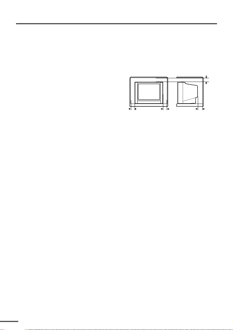
•Never block or cover the cabinet openings for
ventilation. Never install the TV where good
ventilation is unattainable. When installing
this TV, leave spaces for ventilation around
the TV more than the minimum distances
shown in the diagram.
• Do not allow objects or liquid into the
cabinet openings.
• In the event of a fault, unplug the TV and call a service technician. Do not attempt to
repair it by yourself or remove the rear cover.
• The surface of the TV screen is easily damaged. Be very careful with it when handling
the TV. Should the TV screen become soiled, wipe it with a soft dry cloth. Never rub it
forcefully. Never use any cleaner or detergent on it.
• When you don’t use this TV for a long period of time, be sure to unplug it.
10 cm 15 cm
10 cm
15 cm
2
Preparation
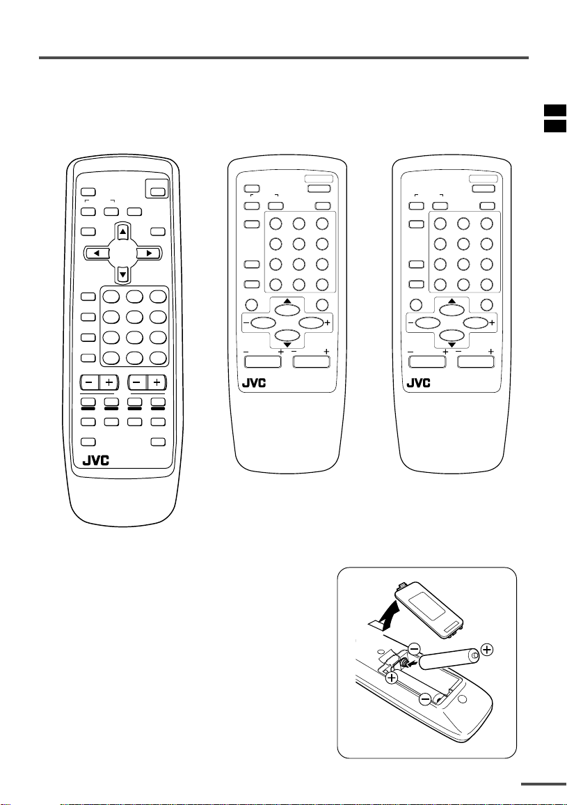
1 Confirm which remote control you have
Your TV comes with one of the three remote controls shown below. Functions you can
operate differ depending on the type of remote control.
RM-C90 RM-C364GY RM-C360GY
ECO
SENSOR
SYSTEM
COLOUR SOUND
DISPLAY
POWER
MUTING
TV/TEXT
ECO
SENSOR
COLOUR
TV/VIDEO
SYSTEM
SOUND
123
456
MENU
TV/VIDEO
123
OFF
TIMER
456
PICTURE
MODE
789
CHANNEL
RETURN+
SCAN
CHANNEL
REVEAL
SUBPAGE CANCEL
HOLD
TEXT
RM-C90
0-/
VOLUME
INDEX SIZE
TV
—
OFF
TIMER
CHANNEL
SCAN
DISPLAY
CHANNEL
789
RETURN
MENU
REMOTE CONTROL UNIT
RM-C364GY
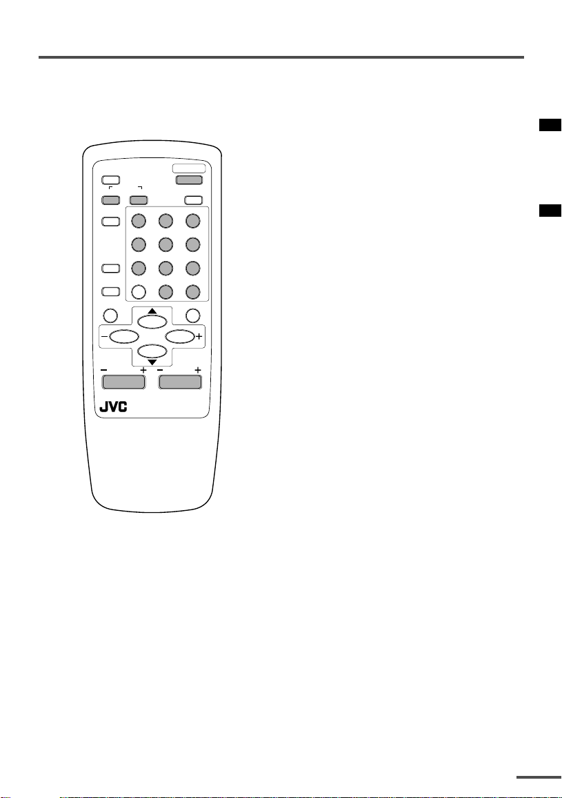
2 Inserting the batteries
Correctly insert two batteries, observing the , and
. polarities and inserting the . end first.
POWER
PICTURE
MODE
COLOUR
TV/VIDEO
SYSTEM
POWER
SOUND
PICTURE
123
MODE
456
OFF
789
TIMER
+
0-/
VOLUME
—
MUTING
CHANNEL
SCAN
DISPLAY
CHANNEL
RETURN
+
0-/
MENU
VOLUME
REMOTE CONTROL UNIT
RM-C360GY
—
MUTING
CAUTION:
Follow the cautions printed on the batteries.
Notes:
• Use AA/R6/UM-3 dry cell batteries.
• If the remote control does not work properly, fit new
batteries.
The supplied batteries are for testing, not regular use.
3
Preparation
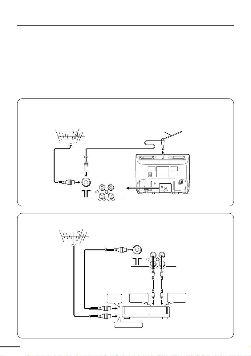
3 Connecting the aerial and external devices
•For further details, refer to the manuals provided with the devices you are connecting.
• Connecting cables are not supplied.
• The front and rear AUDIO/VIDEO input jacks are directly connected so that input to either jack
is output through both. You cannot provide input to both the front and rear jacks at the same
time. Disconnect one input, or use one of the jacks as an output jack only (for monitoring or
recording).
• The rod aerial is supplied with the AV-14A3/AV-14F3/AV-1435/AV-1438.
■ Connecting the aerial and VCR
Connecting the aerial
To install rod aerial:
Install into the top-rear aerial holder. Once installed, it cannot be removed.
VHF/UHF outdoor aerial
VIDEO
AUDIO
IN
OUT
Indoor aerial
Rod aerial
• Illustration of AV-14F3.
Connecting the aerial and VCR
VHF/UHF outdoor aerial
4
1
2
To RF
output
To aerial input
To video
output
VIDEO
AUDIO
IN
OUT
3
To audio
output
VCR
• Illustration of AV-14F3.
Preparation
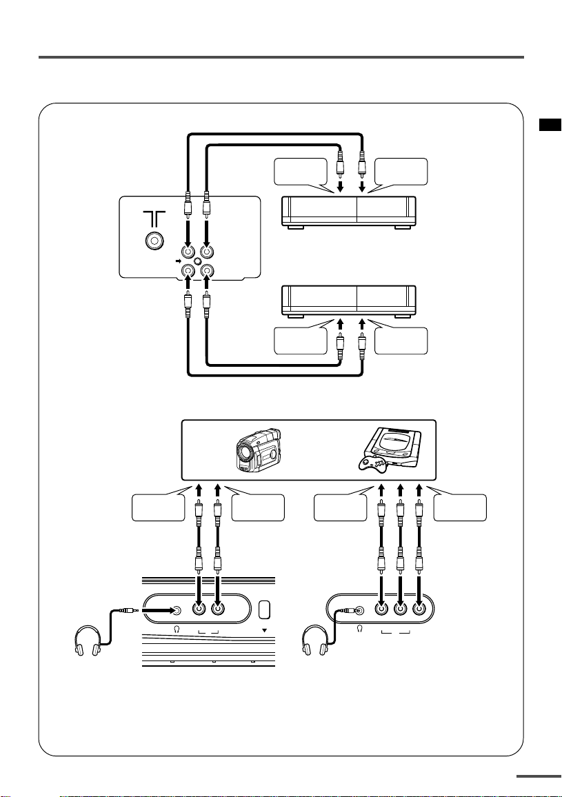
■ Connecting other external devices
• Illustration of AV-21D3.
To video
output
• Illustration of AV-21D3.
To audio
output
VIDEO
AUDIO
IN
OUT
VCR (for playing)
VCR (for recording)
To audio
input
Camcorder or TV game
To audio
output
To video
output
To video
output
To video
input
To audio
output
VIDEO AUDIO
IN
MENU
VIDEO AUDIO
IN
• Illustration of AV-1438.
Headphones
Headphones
• Use the headphones with a stereo mini jack (3.5 mm in diameter). When you connect the
headphones, the TV speakers go off.
For AV-1438:
• Because the front AUDIO jacks are monaural, even stereo input becomes monaural.
5
Preparation
OFF
TIMER
SYSTEM
COLOUR SOUND
MUTING
MENU
DISPLAY
TV/VIDEO
TV/TEXT
123
4 Connecting the power cord
Connect the power cord to the AC outlet.
Operate only from the power source indicated on the rear of the TV.
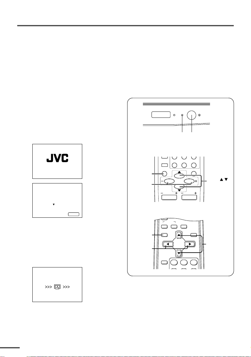
5 SETUP TOUR
When the TV is first turned on it enters the SETUP TOUR mode, and the JVC logo is
displayed. Follow the instructions on the on-screen display to perform the SETUP TOUR.
• In case of resetting that the reason for such as removal, you can set the SETUP TOUR
function on the “MENU 3” menu. For details, see page 16.
1 Press the Main power button
on the TV.
The POWER lamp or POWER/ON
TIMER lamp lights. After the JVC
logo has been displayed, the TV
automatically switches to the
language setting mode.
SETUP TOUR
SETUP TOUR
LANGUAGE
ENGLISH
EXIT BY
OPERATE BY -+
NEXT
DISPL AY
<RM-C360GY/RM-C364GY>
DISPLAY
button
MENU –/+
buttons
ON
POWER
TIMER
POWER lamp Main power button
CHANNEL
RETURN
SCAN
DISPLAY
CHANNEL
+
MENU
0-/
VOLUME
—
MUTING
MENU /
<RM-C90>
buttons
2 Press the MENU M buttons to
select the on-screen language.
3 Press the MENU y button.
The AUTO PROGRAMMING function
will start and the indicator blinks.
SETUP TOUR
NOW PROGRAMMING
STOP BY -+
6
•To stop the AUTO PROGRAMMING function, press the MENU m buttons.
When all the TV channels that can be received on your TV have been preset, the
display goes out and the AUTO PROGRAMMING function operation is completed.
• If a TV channel you want to view is not set to the channel, set it with the MANUAL CH
PRESET function. For details, see page 17.
DISPLAY
button
MENU m
buttons
MENU t
buttons
Basic operation
• The illustration below is for the remote
control RM-C364GY. Your remote control may
not look exactly like the illustrations.
ECO
SENSOR
COLOUR
TV/VIDEO
OFF
TIMER
CHANNEL
SCAN
DISPLAY
CHANNEL
SYSTEM
SOUND
RETURN
REMOTE CONTROL UNIT
RM-C364GY
POWER
PICTURE
MODE
123
456
789
+
MENU
0-/
MUTING
VOLUME
—
1 Press the POWER button to turn
your TV on.
• If your TV does not turn on, press the
Main power button on the TV then press
the POWER button again.
•You can also turn on your TV by pressing
any of the following buttons;
— the CHANNEL m button
— the Number buttons
— the TV/VIDEO button
2 Select a channel.
■ Press the CHANNEL m button.
• Up/down selection cannot be selected
for channels to which the SKIP has been
set to “YES”. See page 18.
■ Press the Number buttons to enter
the channel number.
• If you want to enter a two-digit number,
press the -/— button to select the two
digit mode “—”, then enter the channel
number.
3 Press the VOLUME M button to
adjust the sound.
4To turn your TV off, press the
POWER button.
•We recommend that you press the Main
power button on the TV to turn the main
power off if you do not plan to use your
TV for a long time or if you wish to save
energy.
If the picture is not clear:
Press the COLOUR SYSTEM button to
select another colour system, see page 8.
If the sound is not clear:
Press the SOUND SYSTEM button to select
another sound system, see page 8.
Viewing Images from an External
Device:
Press the TV/VIDEO button to select the
VIDEO mode.
•You can also use the INPUT function to select
the VIDEO mode. For details, refer to page 13.
7
Remote control buttons and functions
ECO SENSOR button
<AV-14A3 does not have this function>
You can adjust this TV so that the screen
automatically adjusts to the optimum
contrast according to the brightness of
your room. This function reduces eye
strain and the power consumption of this
TV.
Press this button to select the desired
mode.
AI ECO SENSOR 1:
The AI ECO SENSOR function switches
on.
Usually, it is recommended to watch the
TV in this mode.
AI ECO SENSOR 2:
The AI ECO SENSOR function switches
on.
If you feel the screen in the “AI ECO
SENSOR 1” mode is too dark, select this
mode.
AI ECO SENSOR OFF:
The AI ECO SENSOR function switches
off.
•You can display on the screen the effect of the
AI ECO SENSOR function.
For details, see “AI ECO DISPLAY” on page 15.
COLOUR SYSTEM button
If the picture is not clear or no colour
appears, change the current colour system
to another colour system.
Press this button to select the colour
system.
In TV mode (channel 1 to 99 and AV):
<AV-1438>
AUTO PAL
NTSC4.43
<Other models>
AUTO PAL
In VIDEO mode:
AUTO PAL
NTSC4.43
AUTO:
Automatic colour system selection.
•For the colour systems in each country or
region, see the table“Broadcasting systems”
on page 22.
• If the picture is not normal in the AUTO
mode, change the AUTO mode to another
colour system.
SECAM
NTSC3.58
SECAM
SECAM
NTSC3.58
PICTURE MODE button
You can select one of three picture
adjustment settings as you like.
Press this button to select a mode.
BRIGHT:
Heightens contrast and sharpness.
STANDARD:
Standardizes picture adjustments.
SOFT:
Softens contrast and sharpness.
•Pressing this button returns all the picture
settings in the “MENU 4” to their default
settings.
8
SOUND SYSTEM button
If the sound is not clear even when the
picture appears normal, change the
current sound system to another sound
system.
Press this button to select the sound
system.
<AV-1438>
<Other models>
B/G I D/K
•For the sound systems in each country or
region, see the table “Broadcasting systems”
on page 22.
•You cannot select any sound system when in
a VIDEO mode.

Remote control buttons and functions
DISPLAY button
You can continuously display the current
channel number or VIDEO mode on the
screen.
Press this button.
To turn the display off, press this button
again.
• When selecting a channel or VIDEO mode
with no input signal, indication of selected
channel or VIDEO mode becomes fixed on the
screen.
RETURN + button
You can set a channel you frequently view
to the Return Channel and you can view
that channel at any time with one-touch.
To set the channel to the Return
Channel:
1 Select the channel you want to set
to the Return Channel.
2 Press this button and hold until the
message “RETURN PLUS
PROGRAMMED!” appears.
• When you turn off the TV, the Return
Channel setting is cancelled.
To view the Return Channel:
Press this button.
•You can view two channels (current channel
and Return Channel) alternately by pressing
this button.
To cancel the Return Channel setting:
Press this button and hold until the
message“RETURN PLUS CANCELLED!”
appears.
If no channel is set to the Return
Channel:
You can view the channel selected right
before the current channel by pressing
this button.
CHANNEL SCAN button
You can quickly view all TV channels
programmes that you can view on your
TV, and search for the programme you
want to view.
1 Press this button to start scanning
TV channels.
The TV channel programmes are each
displayed for several seconds.
• The programmes of TV channels for which
the SKIP function is set to “YES” are not
displayed. (See page 18.)
2 When you find the programme you
want to view, press this button
again to stop scanning.
MUTING button
You can turn the sound off instantly.
Press this button.
To turn the sound on, press this button
again.
OFF TIMER button
You can set the TV to automatically turn
off after a set time.
Press this button to select the period of
time.
•You can set the period of time to a maximum
of 120 minutes in 10 minute increments.
•1 minute before the OFF TIMER function
turns off the TV, “GOOD NIGHT!” appears.
To display the remaining time, press this
button once.
To cancel the OFF TIMER function, press
this button to set the period of time to 0.
• The OFF TIMER function will not turn off the
TV’s main power.
9
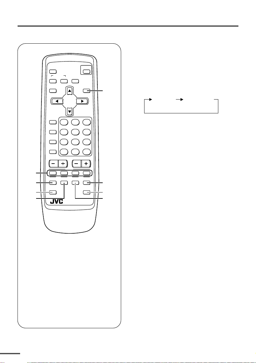
Viewing teletext programmes
TV mode TEXT mode
(TEXT only)
<AV-21FR3/AV-21LTR3 only>
■ Basic operation
ECO
SENSOR
COLOUR SOUND
DISPLAY
TV/VIDEO
OFF
TIMER
PICTURE
MODE
CHANNEL
SCAN
CHANNEL
2
REVEAL
3
SUBPAGE CANCEL
4
5
SYSTEM
MUTING
MENU
123
456
789
RETURN+
TEXT
HOLD
INDEX SIZE
RM-C90
POWER
TV/TEXT
0-/
VOLUME
TV
1 Select a TV channel with a
teletext programme.
2 Press TV/TEXT button to change
the TV mode to the teletext
1
mode.
3 Select a teletext page by
pressing the CHANNEL –/+
button, number buttons or
coloured buttons.
—
6
To return to the TV mode, press the
TV/VIDEO button or the TV/TEXT
button.
• If you have trouble receiving teletext
broadcasts, consult your local dealer or the
teletext station.
7
8
1 TV/TEXT button
2 Coloured buttons
3 REVEAL button
4 SUBPAGE button
5 HOLD button
6 SIZE buttonI
7 CANCEL button
8 INDEX button
10
Viewing teletext programmes
REVEAL
Some teletext pages include hidden text
(such as answers to a quiz).
You can display the hidden text.
Each time you press the REVEAL
button, text is hidden or revealed.
HOLD
You can hold a teletext page on the screen
for as long as you want, even while
several other teletext pages are being
received.
Press the HOLD button.
To cancel the HOLD function, press the
HOLD button again.
CANCEL
You can watch a TV programme even
when in the teletext mode.
1 Press the Number button to enter a
page number, or press a coloured
button.
The TV starts searching for a teletext
page.
2 Press the CANCEL button.
The TV programme appears.
When the TV finds the teletext page, its
page number appears in the upper left
of the screen.
INDEX
You can return to the index page instantly.
Press the INDEX button.
Returns to teletext page 100 or a page
which has been specified.
SUBPAGE
Some teletext pages include sub-pages
that are automatically displayed.
You can hold any sub-page, or view it at
any time.
1 Press the SUBPAGE button to
operate the Sub-page function.
2 Press the Number buttons to enter a
sub-page number.
Example:
3rd sub-page ➞ press 0, 0, 0 and 3.
•You can also select a sub-page by pressing
the red or green button.
To cancel the Sub-page function, press the
SUBPAGE button again.
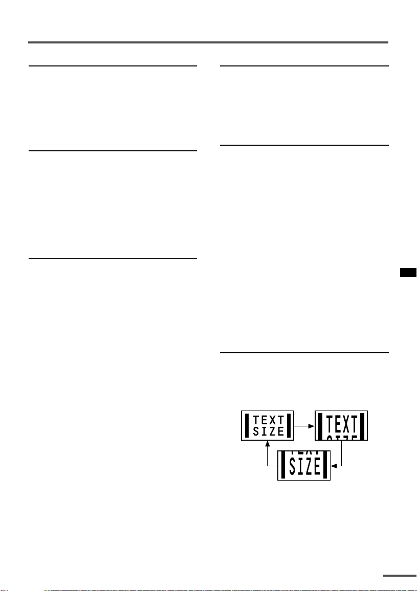
SIZE
You can double the height of the teletext
display.
Press the SIZE button.
The teletext display changes cyclically.
3 Press the CANCEL button to view
the teletext page.
•Pressing the CANCEL button cannot
change the teletext mode to the TV mode.
11
Using the TV’s menus
OFF
TIMER
SYSTEM
COLOUR SOUND
MUTING
MENU
DISPLAY
TV/VIDEO
TV/TEXT
123
This TV has a number of functions you can operate using the menus. To use all your TV’s
functions fully, you need to understand how to use the menus.
<RM-C360GY/RM-C364GY>
CHANNEL
RETURN
+
—
MENU
0-/
VOLUME
MUTING
MENU /
buttons
DISPLAY
button
MENU –/+
buttons
SCAN
DISPLAY
CHANNEL
<RM-C90>
DISPLAY
button
MENU t
MENU m
buttons
buttons
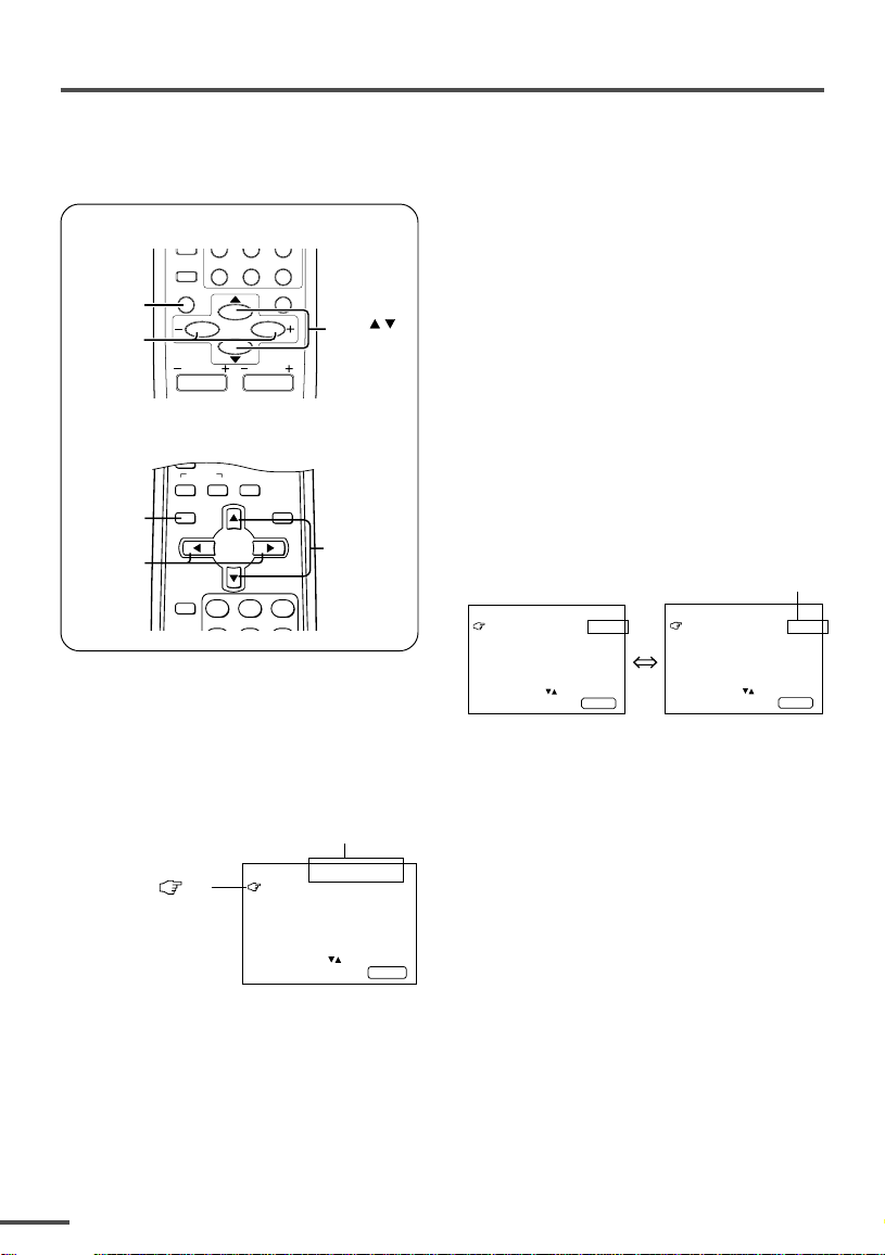
■ Basic operation
1 Press the MENU T buttons.
One of the 4 menus is displayed.
MENU number
MENU 1
The icon on
the left indicates
the currently
selected function.
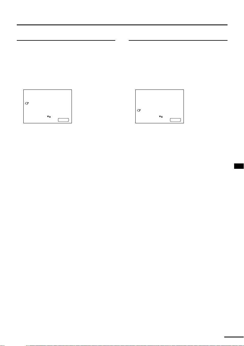
INPUT TV
ON TIMER
PR 1 0:00
VNR OFF
SELECT BY EXIT BY
OPERATE BY -+
DISPL AY
2 Repeatedly press the MENU T
buttons to display a desired
menu.
• If you hold down the y button, the next
menu is displayed.
• If the selected function is on the first line,
pressing the r button displays the
preceding menu.
3 Repeatedly press the MENU T
buttons to select a desired
function.
4 Press the MENU M buttons to
change function settings.
Example:
MENU 2
AUTO SHUTOFF OFF
CHILD LOCK OFF
BLUE BACK ON
AI ECO DISPLAY ON
SELECT BY EXIT BY
OPERATE BY -+
• With some functions, the operation
method may differ.
DISPLAY
Changes the AUTO
SHUTOFF setting.
MENU 2
AUTO SHUTOFF ON
CHILD LOCK OFF
BLUE BACK ON
AI ECO DISPLAY ON
SELECT BY EXIT BY
OPERATE BY -+
DISPLAY
5 Press the DISPLAY button to turn
the display off.
•To operate a menu using the buttons on
the front panel of the TV, refer to
“Operating menus” on page 20.
12
Using the TV’s menus
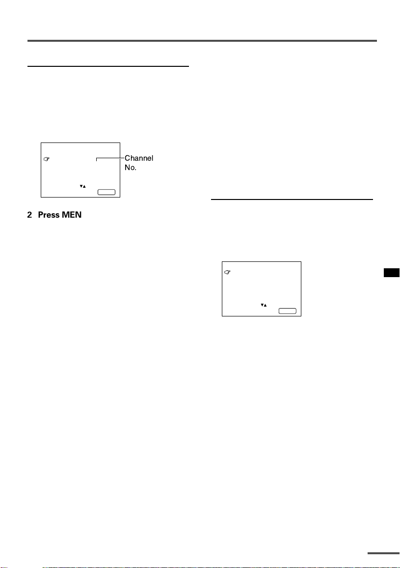
ON TIMER
Your TV will automatically turn on and
tune into the channel you set after the
period of time you set.
1 Press MENU T to display the
“MENU 1” menu, then select
“ON TIMER”.
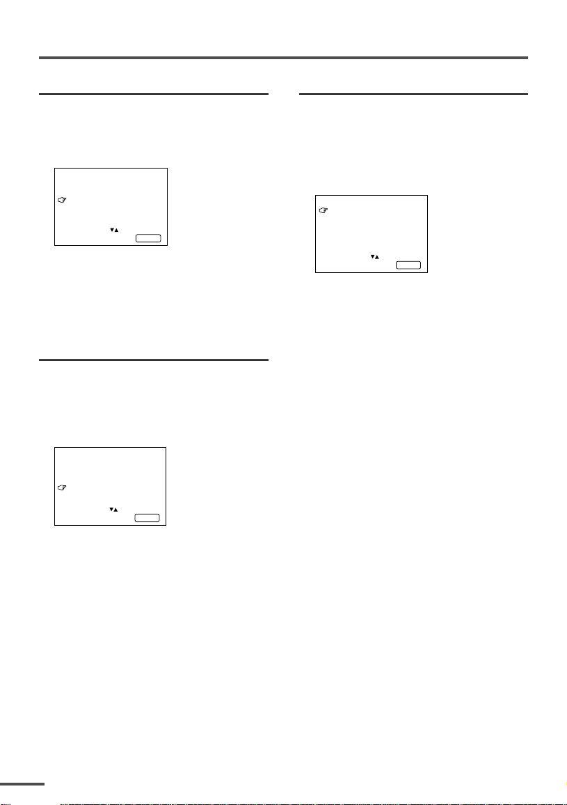
MENU 1
INPUT TV
ON TIMER
PR 1 0:00
VNR OFF
OPERATE BY VOL-+
SELECT BY EXIT BY
PROGRAM BY -+
2 Press MENU M to select a channel
you want to view when the TV turns
on.
3 Press VOLUME M to select the
period of time after which you want
to turn on the TV.
The ON TIMER function starts.
• Each time you press the button, the period
of time changes in 15 minute intervals (up
to 12 hours).
To cancel the ON TIMER function,
press the VOLUME m button to set the
period of time to “0:00”.
4 Press DISPLAY to turn the display
off.
• If you turn off the TV’s main power by
pressing the Main power button, the ON
TIMER function is canceled.
• If you do not turn off the TV after starting
the ON TIMER function, the channel will
automatically switch to the channel set for
the ON TIMER function.
Channel
No.
DISPL AY
When the time set for the ON TIMER
function is reached:
The TV automatically turns on and the
channel set for the ON TIMER function is
displayed.
•For safety reasons the TV will automatically
turn off if no operations are made within
approximately two hours after the TV is
turned on with the ON TIMER function.
• The OFF TIMER function and AUTO
SHUTOFF function have priority over the ON
TIMER function.
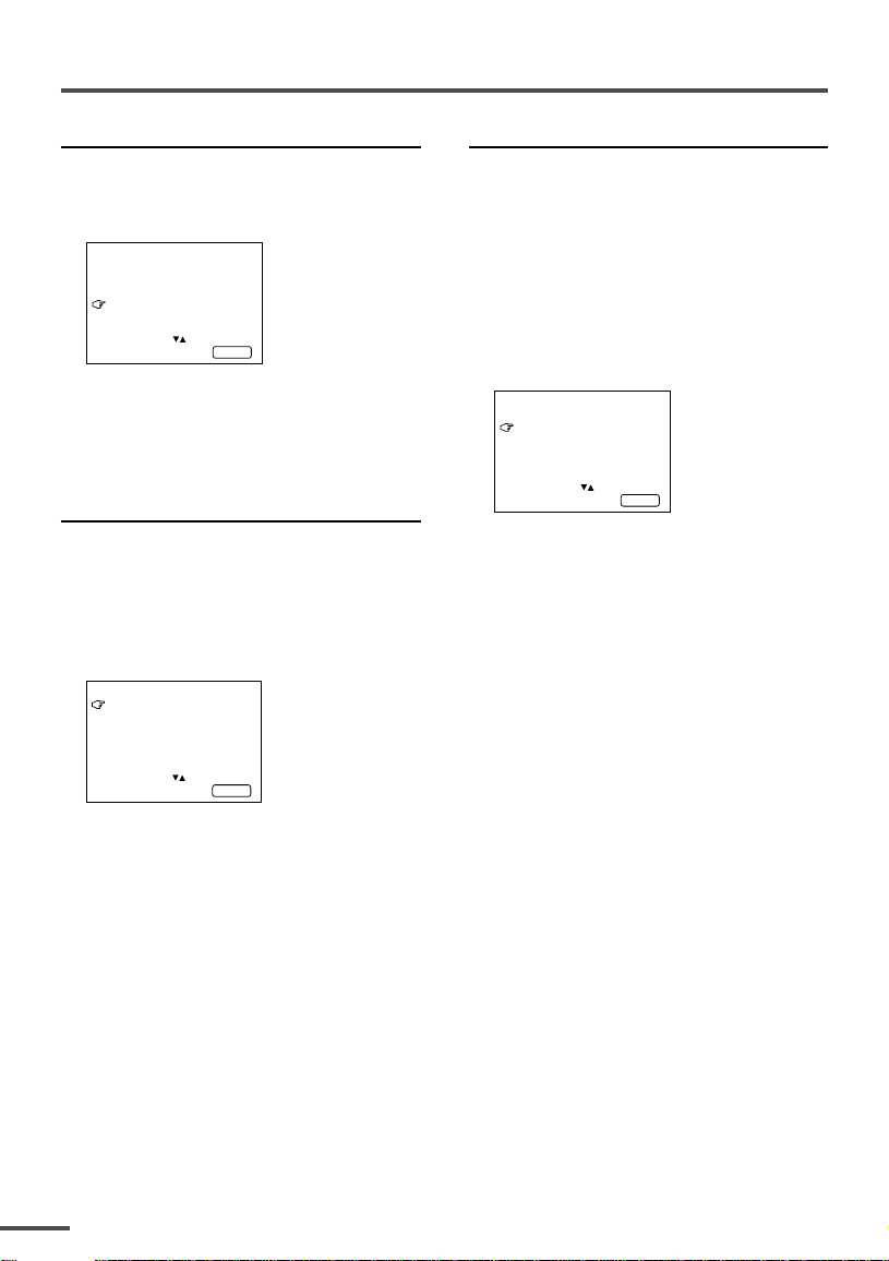
INPUT
You can view images from VCRs or other
devices connected to your TV.
1 Press MENU T to display the
“MENU 1” menu, then select
“INPUT”.
MENU 1
INPUT TV
ON TIMER
PR 1 0:00
VNR OFF
SELECT BY EXIT BY
OPERATE BY -+
2 Press MENU M to select the VIDEO
mode.
TV mode changes to VIDEO mode.
DISPL AY
13
Using the TV’s menus
VNR (Video Noise Reduction)
You can reduce the picture noise.
1 Press MENU T to display the
“MENU 1” menu, then select “VNR”.
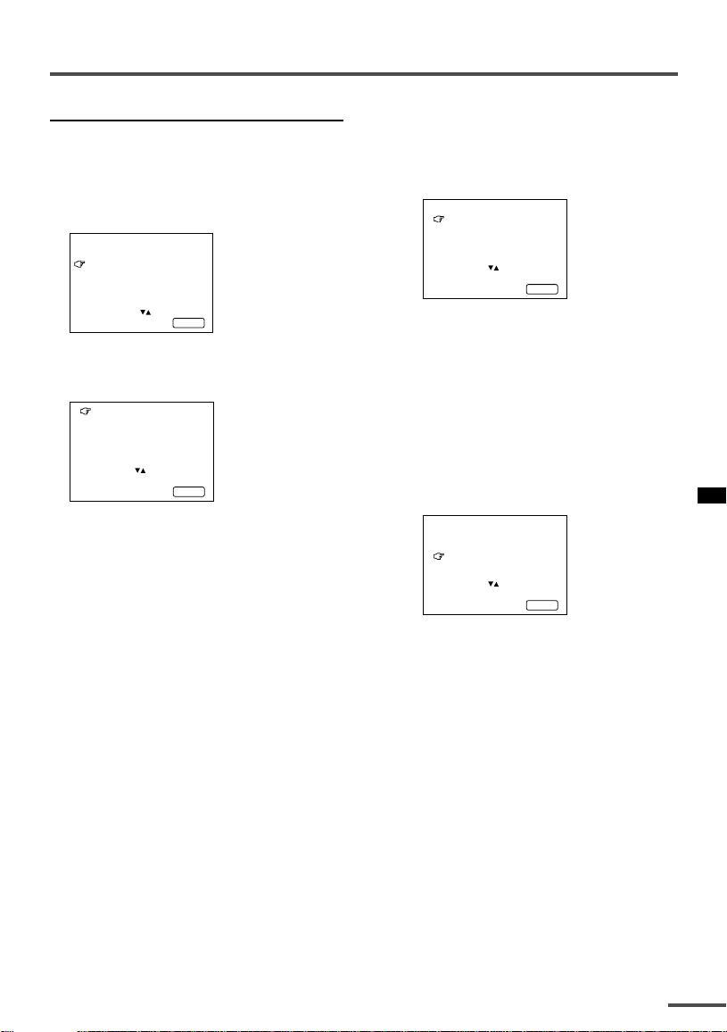
MENU 1
INPUT TV
ON TIMER
PR 1 0:00
VNR ON
SELECT BY EXIT BY
OPERATE BY -+
DISPL AY
2 Press MENU M to select “ON”.
To cancel the VNR function, select
“OFF”.
AUTO SHUTOFF
You can set your TV to turn off if no
signals are received for about 15 minutes
or longer after the end of a broadcast.
1 Press MENU T to display the
“MENU 2” menu, then select “AUTO
SHUTOFF”.
MENU 2
AUTO SHUTOFF ON
CHILD LOCK ON
BLUE BACK ON
AI ECO DISPLAY ON
SELECT BY EXIT BY
OPERATE BY -+
DISPL AY
CHILD LOCK
You can disable the front control buttons
of the TV.
When this function is set to “ON”, the TV
can be operated using only the remote
control.
Use this function to prevent children from
operating the TV without parental consent.
1 Press MENU T to display the
“MENU 2” menu, then select “CHILD
LOCK”.
MENU 2
AUTO SHUTOFF ON
CHILD LOCK ON
BLUE BACK ON
AI ECO DISPLAY ON
SELECT BY EXIT BY
OPERATE BY -+
2 Press MENU M to select “ON”.
To cancel the CHILD LOCK function,
select “OFF”.
• The CHILD LOCK function is canceled when
you turn the power off.
DISPL AY
2 Press MENU M to select “ON”.
To cancel the AUTO SHUTOFF function,
select “OFF”.
• The AUTO SHUTOFF function does not
turn off the TV’s main power.
• The AUTO SHUTOFF will not work for a
VIDEO mode.
14
Using the TV’s menus
BLUE BACK
You can mute the sound and change the
picture into a blue screen while no signals
are received by the TV, or when the
signals are unstable.
1 Press MENU T to display the
“MENU 2” menu, then select “BLUE
BACK”.
MENU 2
AUTO SHUTOFF ON
CHILD LOCK ON
BLUE BACK ON
AI ECO DISPLAY ON
SELECT BY EXIT BY
OPERATE BY -+
2 Press MENU M to select “ON”.
To cancel the BLUE BACK function,
select “OFF”.
•To view a broadcast even when the
reception signal is poor, set the BLUE
BACK function to “OFF”.
•Even when the BLUE BACK function is set
to “OFF”, the sound may not be audible.
DISPL AY
AI ECO DISPLAY
<AV-14A3 does not have this function>
You can display on the screen the effect of
the AI ECO SENSOR function.
1 Press MENU T to display the
“MENU 2” menu, then select “AI
ECO DISPLAY”.
MENU 2
AUTO SHUTOFF OFF
CHILD LOCK OFF
BLUE BACK OFF
AI ECO DISPLAY ON
SELECT BY EXIT BY
OPERATE BY -+
2 Press MENU M to select “ON”.
The clover mark indicating the brightness of
your room is displayed for several seconds
each time the brightness changes. The
number of clover marks displayed on screen
increases as your room becomes darker.
To cancel the AI ECO DISPLAY
function, select “OFF”.
•To switch the AI ECO SENSOR’s mode, see
the “ECO SENSOR button” on page 8.
DISPL AY
15
Using the TV’s menus
SETUP TOUR
You can start the SETUP TOUR function.
1 Press MENU T to display the
“MENU 3” menu, then select
“SETUP TOUR”.
MENU 3
AUTO CH PRESET
MANUAL CH PRESET
SETUP TOUR
LANGUAGE ENGLISH
SELECT BY EXIT BY
OPERATE BY -+
DISPL AY
2 Press MENU M.
JVC logo is appear and the SETUP
TOUR function will start.
For details, see page 6.
LANGUAGE
You can select the language for the onscreen display.
1 Press MENU T to display the
“MENU 3” menu, then select
“LANGUAGE”.
MENU 3
AUTO CH PRESET
MANUAL CH PRESET
SETUP TOUR
LANGUAGE ENGLISH
SELECT BY EXIT BY
OPERATE BY -+
2 Press MENU M to select
language.
The on-screen display indications are
in the selected language.
DISPL AY
AUTO CH PRESET
You can automatically preset all TV
channels that can be received by your TV
to channels.
1 Press MENU T to display the
“MENU 3” menu, then select “AUTO
CH PRESET”.
MENU 3
AUTO CH PRESET
MANUAL CH PRESET
SETUP TOUR
LANGUAGE ENGLISH
SELECT BY EXIT BY
OPERATE BY -+
2 Press MENU M to start the AUTO
CH PRESET function.
“>>>ON SEARCH” is displayed on
the screen.
When all the TV channels that can be
received on your TV have been preset,
the display goes out and the AUTO CH
PRESET function operation is
completed.
To stop the AUTO CH PRESET:
Press the MENU m buttons.
• The AUTO CH PRESET function does not
preset a TV channel to the AV channel
(channel number 0).
• If the TV cannot preset the TV channel you
want to view, preset it manually. For details,
see “MANUAL CH PRESET” on page 17.
DISPL AY
16
Using the TV’s menus
MANUAL CH PRESET
You can manually preset desired TV
channels to desired channels.
If the picture is not clear:
Fine-tune the TV channel.
1 Press MENU T to display the
“MENU 3” menu, then select
“MANUAL CH PRESET”.
MENU 3
AUTO CH PRESET
MANUAL CH PRESET
SETUP TOUR
LANGUAGE ENGLISH
SELECT BY EXIT BY
OPERATE BY -+
DISPL AY
2 Press MENU M.
The sub-menu is displayed.
MANUAL
FINE
SKIP NO
SOUND SYSTEM B/G
EXIT
SELECT BY PR 1 VL
PROGRAM BY -+ EXIT BY
SEARCH BY VOL-+
DISPL AY
• The channel number is displayed as a PR
number. For example, channel 1 will be
displayed as PR 1. However, the AV
channel will be displayed as AV.
3 Press MENU M to select the
channel number.
4 Press VOLUME M to start
searching for the TV channel.
“>>>” or “<<<” is displayed on the
screen.
When the TV finds a TV channel, the
“>>>” or “<<<” display goes out,
and the TV channel is preset to the
currently selected channel number.
• If the TV channel you want to preset is not
displayed, repeat step 4 until the TV finds
the TV channel you want to preset.
•To stop the MANUAL CH PRESET function,
press any button other than the VOLUME
m button.
1 Press MENU t to select “FINE”.
MANUAL
FINE
SKIP NO
SOUND SYSTEM B/G
EXIT
SELECT BY PR 3 VL
PROGRAM BY -+ EXIT BY
FINE BY VOL-+
DISPL AY
2 Hold VOLUME m down to fine-tune
the TV channel so that the best image
is displayed on screen.
“>” or “<” indicates that the TV is finetuning the TV channel.
If the sound is not clear:
1 Press MENU t to select “SOUND
SYSTEM”.
MANUAL
FINE
SKIP NO
SOUND SYSTEM M
EXIT
SELECT BY PR 3 VL
PROGRAM BY -+ EXIT BY
CHANGE BY VOL-+
DISPL AY
2 Press VOLUME m to select the
appropriate sound system.
•For the sound systems in each country
or region, refer to the table
“Broadcasting systems” on page 22.
5 Press MENU T to select
“MANUAL”.
6 Repeat steps 3 to 5 if you want to
preset another TV channel to a
channel.
17
Using the TV’s menus
SKIP
You can set undesired channels to be
skipped. Channels set to be skipped
cannot be selected by the CHANNEL m
buttons nor the CHANNEL SCAN button.
• Channels to which TV channels have not
been preset are automatically set to be
skipped.
1 Press MENU T to display the
“MENU 3” menu, then select
“MANUAL CH PRESET”.
2 Press MENU M.
The sub-menu is displayed.
3 Press MENU T to select “SKIP”.
MANUAL
FINE
SKIP NO
SOUND SYSTEM M
EXIT
SELECT BY PR 3 VL
PROGRAM BY -+ EXIT BY
YES/NO BY VOL-+
4 Press MENU M to select the
channel you want to skip.
5 Press VOLUME M to select “YES”.
The channel is set to be skipped.
To cancel the SKIP function, select
“NO”.
DISPL AY
Picture Adjustments
You can adjust the picture as you like.
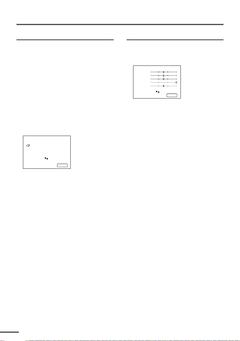
1 Press MENU T to display the
“MENU 4” menu.
MENU 4
TINT
COLOUR
BRIGHT
CONT.
SHARP
SELECT BY EXIT BY
OPERATE BY -+
2 Press MENU T to select an item
and press MENU M to adjust it.
TINT* — : Reddish + : Greenish
COLOUR — : Lighter + : Deeper
BRIGHT — : Darker + : Brighter
CONT. — : Lower + : Higher
SHARP — : Softer + : Sharper
* TINT (tint) is displayed only when
viewing images from NTSC3.58 or
NTSC4.43 colour systems.
DISPL AY
6 Repeat steps 4 and 5 if you want to
set another channel to skip.
18
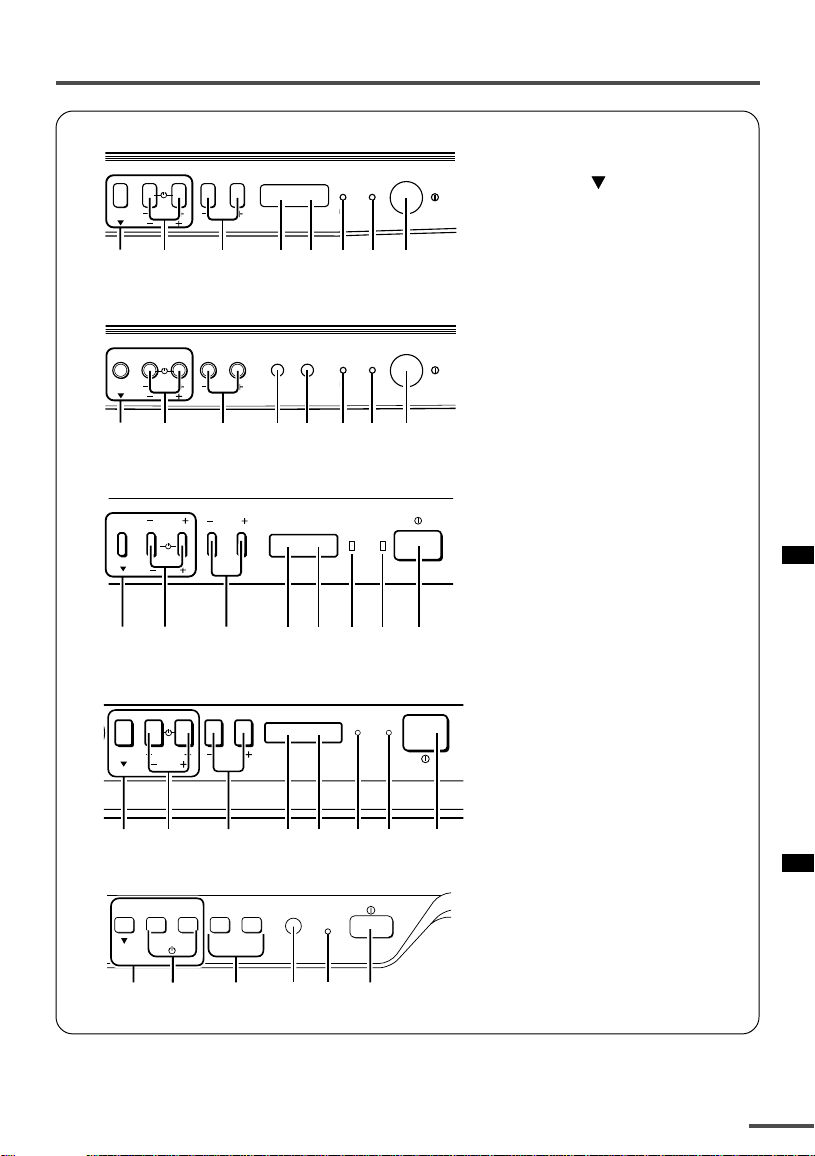
Using the buttons on the TV
<AV-21D3/AV-21LT3/AV-21LTR3>
1 MENU buttons
• MENU
ON
POWER
5
TIMER
6
7
MENU
1
CHANNEL
2
VOLUME
EXIT
3
49
<AV-21Q3>
ON
POWER
5
TIMER
6
7
MENU
1
CHANNEL
2
VOLUME
EXIT
3
49
<AV-21E3>
CHANNEL
MENU VOLUME
EXIT
POWERON TIMER
12 3 76549
• MENU m buttons
2 CHANNEL m buttons
3 VOLUME m buttons
4 AI ECO sensor
5 Remote control sensor
6 ON TIMER lamp
The light is switched on
while ON TIMER function
is operating.
7 POWER lamp
When the Main power is
on, the light is red.
8 POWER/ON TIMER lamp
When the Main power is
on, the light is green.
When ON TIMER function
is on, it is red.
9 Main power button
button
<AV-14F3/AV-1435/AV-1438/AV-20N3/AV-21F3/AV-21FR3>
MENU
CHANNEL
1
2
VOLUME
EXIT
3
POWERON TIMER
45 9
67
<AV-14A3>
CHANNEL VOLUME
MENU
–+++
––
EXIT
POWER/
ON TIMER
83921 5
19
Using the buttons on the TV
Basic operation
• Check to make sure the CHILD LOCK
function is set to “OFF”. When the CHILD
LOCK function is set to “ON”, the TV cannot
be operated using the front control buttons.
For details, see “CHILD LOCK” on page 14.
1 Press CHANNEL M to turn the TV
on from standby mode.
2 Press CHANNEL M to select a
channel.
3 Press VOLUME M to adjust the
volume.
4To turn your TV off, press the Main
power button to turn off the TV’s
main power.
To change the TV mode to the VIDEO
mode:
• Select the VIDEO mode with the INPUT
function in “MENU 1”.
Operating menus
You can operate functions in menus using
the front control buttons on the TV.
1 Press MENU y to display a menu.
2 Press MENU y repeatedly to display
the menu you want to use.
3 Press MENU y to select the desired
function or item.
4 Press MENU M or VOLUME M to
carry out the desired operation.
For details, see the description for each
function.
5 Press VOLUME M to turn the menu
display off.
To turn the sub-menu display off:
1 Press MENU y to select “EXIT”.
MANUAL
FINE
SKIP NO
SOUND SYSTEM M
EXIT
SELECT BY PR 3 VL
PROGRAM BY -+ EXIT BY
EXIT BY VOL-+
DISPL AY
20
2 Press VOLUME m to turn the display
off.
Loading…
Руководства JVC AV2115EE Размер файлов: 2178 KB, Язык: English, Формат: pdf, Платформа: Windows/Linux, Дата: 2017-03-29
На данной странице вы можете скачать руководства JVC AV2115EE. Мы предлагаем вам ознакомиться с руководством пользователя, инструкцией по сервисному обслуживанию и ремонту.
Также здесь вы найдете список заказных номеров на комплектующие JVC AV2115EE.
Все файлы предоставляются исключительно в ознакомительных целях. И не являютя руководством по ремонту, а направлены лишь на то чтобы помочь вам более детально ознакомиться с принципом построения устройства.
Содержимое представленных здесь руководств требуют от вас знания технического английского языка.
Если вы собираетесь скачать руководство по сервисному обслуживанию JVC AV2115EE, иными словами сервис мануал, вы дожны обладать хотя бы минимальными познаниями в области электроники и пониманием базовых принципов работы электромеханических устройств.
Для просмотра руководств вам понадобится Adobe Acrobat Reader версии 9 и выше либо другая программа для просмотра pdf файлов.
В связи с популярностью информации представленной на сайте и ее бесплатного предоставления конечному пользователю, убедительная просьба использовать специальные программные продукты для многопотокового скачивания файлов.
Руководства для JVC AV2115EE
- Руководство пользователя (User manual)
- Руководство по сервисному обслуживанию (Service manual)
- Руководство по ремонту (Repair manual)
- Перечень комплектующих (PartList)
LCT1195-001B-H
0502-Ki-NIC-JMT
© 2002 VICTOR COMPANY OF JAPAN, LIMITED
COLOUR TELEVISION
INSTRUCTIONS
Thank you for buying this JVC
colour television.
To make sure you understand how to
use your new TV, please read this
manual thoroughly before you begin.
AV-1415EE
AV-1435EE
AV-2105EE
AV-2115EE
AV-2135EE
AV-1435TEE
AV-2135TEE
Contents
Safety precautions 2
Preparation 3
1 Confirm which remote control you have
……
3
2 Inserting the batteries
……………………………..
3
3
Connecting the aerial and external devices
…
4
4 Connecting the power cord
……………………
6
5 SETUP TOUR
……………………………………….
6
Basic operation 7
Remote control buttons and functions 8
ECO SENSOR button
……………………………….
8
PICTURE MODE button
……………………………
8
COLOUR SYSTEM button
………………………..
8
SOUND SYSTEM button
………………………….
8
DISPLAY button
………………………………………
9
RETURN + button
……………………………………
9
CHANNEL SCAN button
…………………………..
9
MUTING button
………………………………………
9
OFF TIMER button
…………………………………..
9
Viewing teletext programmes 10, 11
Using the TV’s menus 12
Basic operation
……………………………………..
12
ON TIMER
……………………………………………..
13
INPUT
…………………………………………………..
13
VNR
………………………………………………………
14
AUTO SHUTOFF
……………………………………
14
CHILD LOCK
………………………………………….
14
BLUE BACK
…………………………………………..
15
AI ECO DISPLAY
……………………………………
15
SETUP TOUR
………………………………………..
16
LANGUAGE
…………………………………………..
16
AUTO CH PRESET
…………………………………
16
MANUAL CH PRESET
…………………………….
17
SKIP
……………………………………………………..
18
Picture Adjustments
………………………………
18
Using the buttons on the TV 19
Troubleshooting 21
Specifications 22
LCT1195-001B-H_Cover 11/6/2002, 15:032
Инструкция телевизора JVC AV2115EE Размер: 1202 KB, Язык: Английский, Расширение: .pdf, Платформа: Adobe Acrobat, Дата: 2018-01-23
Руководство пользователя содержит основные технические характеристики устройства.
Комплект поставки может отличаться от описанного в руководстве.
Отдельная глава руководства пользователя посвящена условиям эксплуатации устройства. Описаны всевозможные варианты монтажа и установки.
Подробно описаны функции и особенности органов управления устройством.
Инструкция JVC AV2115EE предназначена для технически образованных людей и при детальном изучении гарантирует безопасную и долговременную работу устройства.
Руководство пользователя телевизора JVC AV2115EE содержит описание процедуры первоначальной настройки и подключения устройства и выполнение процедур сервисного обслуживания и подготовки расходных материалов.
Для изучения файла вам необходимо обладать хотя бы минимальным знанием английского языка, так как инструкция на русском для телевизора JVC AV2115EE пока еще не выпущена.
Описание специальных функций описано в отдельной главе инструкции.
Последняя глава руководства по эксплуатации содержит описание основных неисправностей телевизора и перечень основных действий по их устранению.
Пожалуйста используйте специальное программное обеспечение для скачивания файлов и по возможности дождитесь окончания загрузки первого файла перед началом загрузки второго.
Перечень основных разделов руководства пользователя телевизора JVC AV2115EE
- Технические характеристики
- Варианты монтажа
- Безопасность
- Органы управления
- Настройка устройства
- Стандартные функции
- Основные неисправности телевизора JVC AV2115EE
SERVICE MANUAL
COPYRIGHT © 2003 VICTOR COMPANY OF JAPAN, LTD.
No.52027B
2003/03
AV-2115EE
AV-2116EE
COLOUR TELEVISION
52027B
2003
03
AV-2115EE/SK,
AV-2116EE/SK
The following items for the AV-2115EE/SK, AV-2116EE/SK models were changed partly from AV-2115EE
models.
Therefore, this service manual describes only the items which differ from those of the AV-2115EE model
service manual.
For details other than those described in this manual, please refer to the AV-2115EE model service manual
(No.52027, Aug.2002).
OUTLINE
HOW TO IDENTIFY MODELS
Since the production place of the model has been changed, changes are presented here.
«AV-2115EE/SK«, «AV-2116EE/SK» is added to the serial No. under at the Rating label.
MODEL
Indicated
SERIAL No.
AV-2115EE
AV-2115EE/SK
AV-2116EE/SK
BASIC CHASSIS
CG
Supplementary
AV-2115EE
AV-2116EE
1-2 (No.52027B)
DIFFERENCE LIST
USING P.W.BOARD (Page 34)
EXPLODED VIEW PARTS LIST
EXPLODED VIEW (Page 36)
PRINTED WIRING BOARD PARTS LIST
[AV-2115EE/SK]
Since there are many differences in MAIN PW BOARD, lists of all the parts are described here.
MAIN PW BOARD(SCG-1460A-H2)
P.W.B ASS’Y
AV-2115EE
AV-2115EE/SK
AV-2116EE/SK
DESCRIPTION
MAIN PWB
SCG-1442A-H2
SCG-1460A-H2
SCG-1465A-H2
Non compatible
CRT SOCKET PWB
—
—
SCG-3003A-CK
Ref. No.
PARTS No.
PARTS NAME
DESCRIPTION
AV-2115EE
AV-2115EE/SK
AV-2116EE/SK
V01
A51LMV10X
—
PICTURE TUBE
V01
—
A51KQK99X01
ITC
L01
QQW0006-001
QQW0077-001
DEG COIL
DY01
CE20336-00A
—
DEF YOKE
T1522
QQH0131-001
QQH0134-001-KD
F.B.TRANSF.
1
GG10196-001A-H
GG10196-001C-HK FRONT CABINET
3
GG30054-001A-H
GG30054-001B-H
POWER KNOB
5
GG20030-001A-H
GG20030-001D-H
CONTROL KNOB
6
GG30055-001A-H
GG30055-001B-H
REMOCON LENS
10
A75034-B
—
PC MAGNET
11
CE42153-00AJ1
—
WEDGE ASSY
(x3)
14
CM12863-A02-MH
GG10049-002A-HK REAR COVER
17
GG20024-001A-H
GG20024-001B-H
RATING LABEL
Ref. No.
PARTS No.
PARTS NAME
DESCRIPTION
IC1301
NN5198K
IC
IC1301
NN5198K
IC
IC1421
AN5522
IC
IC1651
AN5265
IC
IC1701
MN1873287JK1
IC(MCU)
IC1702
AT24C08-21DMG3 IC
(SERVICE)
IC1703
L78LR05E-MA
IC
IC1704
GP1UM281QK
IR DETECT UNIT
38kHz
IC1921
STR-W5753A/F5
IC
IC1971
BA17809T
IC
IC1972
BA17805T
IC
Q1102
2SC5083/L-P/-T
TRANSISTOR
Q1301
2SB709A/QR/-X
TRANSISTOR
Q1302
2SD601A/QR/-X
TRANSISTOR
Q1351
STC344-T
TRANSISTOR
Q1352
STC344-T
TRANSISTOR
Q1353
STC344-T
TRANSISTOR
Q1401
DTC124ESA-T
DIGI TRANSISTOR
Q1402
2SD601A/QR/-X
TRANSISTOR
Q1521
2SC2655/Y/-T
TRANSISTOR
Q1522
2SD2627-YB11
POW TRANSISTOR
Q1571
2SA1208/ST/Z1-T
TRANSISTOR
Q1572
2SD601A/QR/-X
TRANSISTOR
Q1651
2SD601A/QR/-X
TRANSISTOR
Q1652
2SD601A/QR/-X
TRANSISTOR
Q1653
2SB709A/QR/-X
TRANSISTOR
Q1702
2SD601A/QR/-X
TRANSISTOR
Q1703
2SD601A/QR/-X
TRANSISTOR
Q1708
UN2212-X
DIGI TRANSISTOR
Q1709
2SB709A/QR/-X
TRANSISTOR
Q1803
2SC1815/YG/-T
TRANSISTOR
Q1804
2SD601A/QR/-X
TRANSISTOR
Q1974
2SA966/OY/-T
TRANSISTOR
Q1975
UN2212-X
DIGI TRANSISTOR
D1001
MTZJ33A-T2
Z DIODE
D1102
IM-BW
BUS WIRE
D1301
MTZJ9.1B-T2
Z DIODE
D1302
MTZJ9.1B-T2
Z DIODE
D1303
MA3091/M/-X
Z DIODE
D1305
AK04-T2
SB DIODE
D1306
QRE121J-121Y
C RESISTOR
120
1/2W J
D1341
MA111-X
SI DIODE
D1421
MTZJ75-T2
Z DIODE
D1423
1SR124-400A-T2
SI DIODE
D1425
MA111-X
SI DIODE
D1427
MTZJ27B-T2
Z DIODE
D1501
MTZJ6.8C-T2
Z DIODE
D1551
RGP10J-5025-T3
SI DIODE
D1552
RGP10J-5025-T3
SI DIODE
D1553
MTZJ9.1B-T2
Z DIODE
D1554
MA111-X
SI DIODE
D1557
1SR124-400A-T2
SI DIODE
D1571
MTZJ7.5S-T2
Z DIODE
Ref. No.
PARTS No.
PARTS NAME
DESCRIPTION

AV-2115EE
AV-2116EE
(No.52027B)1-3
D1581
MTZJ20B-T2
Z DIODE
D1582
RGP10J-5025-T3
SI DIODE
D1651
MA111-X
SI DIODE
D1652
MTZJ12C-T2
Z DIODE
D1653
MA111-X
SI DIODE
D1654
MTZJ12C-T2
Z DIODE
D1655
MA111-X
SI DIODE
D1656
MA111-X
SI DIODE
D1657
MA111-X
SI DIODE
D1701
MA111-X
SI DIODE
D1704
SLR-342VR-T16
LED
RED
D1705
SLR-342DU-T16
LED
ORANGE
D1707
MA111-X
SI DIODE
D1731
MA111-X
SI DIODE
D1920
1SS133-T2
SI DIODE
D1921
RGP10J-5025-T3
SI DIODE
D1925
RGP10J-5025-T3
SI DIODE
D1927
MTZJ36A-T2
Z DIODE
D1928
MTZJ3.3A-T2
Z DIODE
D1930
RGP10M-5010-T3 SI DIODE
D1931
MA111-X
SI DIODE
D1933
MTZJ16C-T2
Z DIODE
D1941
RU3AM-LFC4
SI DIODE
D1942
RGP30B-F1
SI DIODE
D1943
RGP10J-5025-T3
SI DIODE
D1982
MA111-X
SI DIODE
D1983
MA111-X
SI DIODE
PC1701
P1241-04
PHOTO CONDUCTOR
C1001
QETN1HM-106Z
E CAPACITOR
10uF 50V M
C1002
NCB31HK-103X
C CAPACITOR
0.01uF 50V K
C1004
QETN1CM-477Z
E CAPACITOR
470uF 16V M
C1005
QFV71HJ-104Z
MF CAPACITOR
0.1uF 50V J
C1008
QETN1HM-475Z
E CAPACITOR
4.7uF 50V M
C1103
QETN1EM-476Z
E CAPACITOR
47uF 25V M
C1104
NCB31HK-472X
C CAPACITOR
4700pF 50V K
C1105
NCB31HK-472X
C CAPACITOR
4700pF 50V K
C1106
NCB31HK-472X
C CAPACITOR
4700pF 50V K
C1107
NCB31HK-472X
C CAPACITOR
4700pF 50V K
C1110
NRSA63J-0R0X
MG RESISTOR
0
1/16W J
C1112
QETN1EM-476Z
E CAPACITOR
47uF 25V M
C1113
NCB31HK-472X
C CAPACITOR
4700pF 50V K
C1114
NCB31HK-103X
C CAPACITOR
0.01uF 50V K
C1115
NCB31HK-103X
C CAPACITOR
0.01uF 50V K
C1116
NCB31HK-103X
C CAPACITOR
0.01uF 50V K
C1117
QFV71HJ-224Z
MF CAPACITOR
0.22uF 50V J
C1119
QETN1HM-474Z
E CAPACITOR
0.47uF 50V M
C1120
NDC31HJ-121X
C CAPACITOR
120pF 50V J
C1121
NCB31HK-103X
C CAPACITOR
0.01uF 50V K
C1122
NCB31HK-103X
C CAPACITOR
0.01uF 50V K
C1162
NCB31HK-152X
C CAPACITOR
1500pF 50V K
C1301
NCB31HK-123X
C CAPACITOR
0.012uF 50V K
C1302
QETN1HM-475Z
E CAPACITOR
4.7uF 50V M
C1303
NDC31HJ-100X
C CAPACITOR
10pF 50V J
C1304
QFV71HJ-474Z
MF CAPACITOR
0.47uF 50V J
C1305
QETN1HM-474Z
E CAPACITOR
0.47uF 50V M
C1306
NCB31HK-103X
C CAPACITOR
0.01uF 50V K
C1307
QETN1CM-477Z
E CAPACITOR
470uF 16V M
C1308
QETN1CM-107Z
E CAPACITOR
100uF 16V M
C1309
NCB31HK-103X
C CAPACITOR
0.01uF 50V K
C1310
NDC31HJ-221X
C CAPACITOR
220pF 50V J
C1311
NCB31HK-103X
C CAPACITOR
0.01uF 50V K
C1312
QENC1HM-474Z
BP E CAPACITOR
0.47uF 50V M
C1313
QETN1HM-335Z
E CAPACITOR
3.3uF 50V M
C1314
NCB31HK-103X
C CAPACITOR
0.01uF 50V K
C1315
QETN1CM-107Z
E CAPACITOR
100uF 16V M
C1316
QETN1HM-106Z
E CAPACITOR
10uF 50V M
C1317
NCB31EK-473X
C CAPACITOR
0.047uF 25V K
C1321
NDC31HJ-120X
C CAPACITOR
12pF 50V J
Ref. No.
PARTS No.
PARTS NAME
DESCRIPTION
C1322
NCB31EK-273X
C CAPACITOR
0.027uF 25V K
C1323
QETN1HM-474Z
E CAPACITOR
0.47uF 50V M
C1324
QETN1HM-106Z
E CAPACITOR
10uF 50V M
C1325
QENC1HM-106Z
BP E CAPACITOR
10uF 50V M
C1326
NCS21HJ-221X
C CAPACITOR
220pF 50V J
C1341
QETN1HM-106Z
E CAPACITOR
10uF 50V M
C1352
QFZ0097-103
MM CAPACITOR
0.01uF
C1354
NDC31HJ-271X
C CAPACITOR
270pF 50V J
C1355
NDC31HJ-221X
C CAPACITOR
220pF 50V J
C1356
NDC31HJ-331X
C CAPACITOR
330pF 50V J
C1357
QETN1AM-477Z
E CAPACITOR
470uF 10V M
C1365
QENC1HM-105Z
BP E CAPACITOR
1uF 50V M
C1366
QENC1HM-105Z
BP E CAPACITOR
1uF 50V M
C1367
QENC1HM-105Z
BP E CAPACITOR
1uF 50V M
C1401
QFV71HJ-474Z
MF CAPACITOR
0.47uF 50V J
C1423
QCS32HJ-180Z
C CAPACITOR
18pF 500V J
C1424
QFLC2AJ-103Z
M CAPACITOR
0.01uF 100V J
C1426
QFLC1HJ-102Z
M CAPACITOR
1000pF 50V J
C1427
QETN1VM-107Z
E CAPACITOR
100uF 35V M
C1428
QETN1VM-107Z
E CAPACITOR
100uF 35V M
C1429
QETN1HM-106Z
E CAPACITOR
10uF 50V M
C1430
QFN32AJ-472Z
M CAPACITOR
4700pF 100V J
C1433
QEHR1HM-475Z
E CAPACITOR
4.7uF 50V M
C1435
QETM1EM-228
E CAPACITOR
2200uF 25V M
C1436
QFV71HJ-334Z
MF CAPACITOR
0.33uF 50V J
C1437
NCB31HK-104X
C CAPACITOR
0.1uF 50V K
C1501
QETN1AM-477Z
E CAPACITOR
470uF 10V M
C1502
NCB31HK-103X
C CAPACITOR
0.01uF 50V K
C1503
QETN1HM-106Z
E CAPACITOR
10uF 50V M
C1523
QETN1EM-476Z
E CAPACITOR
47uF 25V M
C1525
QFZ0200-942
MPP CAPACITOR
9400pF 1.5kV H
C1526
QFLC1HJ-822Z
M CAPACITOR
8200pF 50V J
C1527
QFZ0199-374
MPP CAPACITOR
0.37uF
C1529
QFLC1HJ-332Z
M CAPACITOR
3300pF 50V J
C1531
QEZ0203-107
E CAPACITOR
100uF 160V M
C1552
QETM1VM-108
E CAPACITOR
1000uF 35V M
C1554
QETN2EM-475Z
E CAPACITOR
4.7uF 250V M
C1555
QFLC2AJ-104Z
M CAPACITOR
0.1uF 100V J
C1557
QETN1HM-107Z
E CAPACITOR
100uF 50V M
C1571
QETN1AM-107Z
E CAPACITOR
100uF 10V M
C1572
QETN1EM-476Z
E CAPACITOR
47uF 25V M
C1581
QFV71HJ-104Z
MF CAPACITOR
0.1uF 50V J
C1652
NCB31HK-473X
C CAPACITOR
0.047uF 50V K
C1653
QETN1HM-106Z
E CAPACITOR
10uF 50V M
C1654
QETN1CM-477Z
E CAPACITOR
470uF 16V M
C1655
QETN1HM-106Z
E CAPACITOR
10uF 50V M
C1656
QENC1HM-105Z
BP E CAPACITOR
1uF 50V M
C1657
QETN1EM-107Z
E CAPACITOR
100uF 25V M
C1658
QETN1EM-227Z
E CAPACITOR
220uF 25V M
C1659
QETN1HM-475Z
E CAPACITOR
4.7uF 50V M
C1663
NCB31HK-102X
C CAPACITOR
1000pF 50V K
C1664
QETN1CM-107Z
E CAPACITOR
100uF 16V M
C1665
NCB31HK-103X
C CAPACITOR
0.01uF 50V K
C1701
QETN1HM-106Z
E CAPACITOR
10uF 50V M
C1705
QETN1CM-477Z
E CAPACITOR
470uF 16V M
C1706
NCB31HK-104X
C CAPACITOR
0.1uF 50V K
C1707
NCB31HK-103X
C CAPACITOR
0.01uF 50V K
C1708
QETN1AM-108Z
E CAPACITOR
1000uF 10V M
C1709
NCB31HK-103X
C CAPACITOR
0.01uF 50V K
C1710
QETN1CM-107Z
E CAPACITOR
100uF 16V M
C1711
NCB31HK-103X
C CAPACITOR
0.01uF 50V K
C1712
NCB31HK-103X
C CAPACITOR
0.01uF 50V K
C1713
NCB31HK-103X
C CAPACITOR
0.01uF 50V K
C1716
NDC31HJ-181X
C CAPACITOR
180pF 50V J
C1717
NDC31HJ-181X
C CAPACITOR
180pF 50V J
C1718
NCB31HK-103X
C CAPACITOR
0.01uF 50V K
C1719
QETN1HM-105Z
E CAPACITOR
1uF 50V M
C1720
NCB31HK-103X
C CAPACITOR
0.01uF 50V K
C1721
NCB31EK-333X
C CAPACITOR
0.033uF 25V K
C1722
NDC31HJ-101X
C CAPACITOR
100pF 50V J
Ref. No.
PARTS No.
PARTS NAME
DESCRIPTION
AV-2115EE
AV-2116EE
1-4 (No.52027B)
C1724
NDC31HJ-560X
C CAPACITOR
56pF 50V J
C1728
NDC31HJ-181X
C CAPACITOR
180pF 50V J
C1729
NDC31HJ-181X
C CAPACITOR
180pF 50V J
C1730
NCB31HK-103X
C CAPACITOR
0.01uF 50V K
C1741
IM-BW
BUS WIRE
C1742
IM-BW
BUS WIRE
C1743
IM-BW
BUS WIRE
C1744
NCB31HK-103X
C CAPACITOR
0.01uF 50V K
C1805
QETN1CM-227Z
E CAPACITOR
220uF 16V M
C1806
QETN1CM-477Z
E CAPACITOR
470uF 16V M
C1811
QETN1HM-106Z
E CAPACITOR
10uF 50V M
C1841
NCB31HK-152X
C CAPACITOR
1500pF 50V K
C1901
QFZ9078-224
MPP CAPACITOR
0.22uF
C1904
QCZ9015-102Z
C CAPACITOR
1000pF AC250V Z
C1905
QCZ9015-102Z
C CAPACITOR
1000pF AC250V Z
C1907
QCZ9015-102Z
C CAPACITOR
1000pF AC250V Z
C1909
QEZ0552-127
E CAPACITOR
120uF
C1910
QFZ9078-473
MPP CAPACITOR
0.047uF
C1922
QFLC1HJ-104Z
M CAPACITOR
0.1uF 50V J
C1924
QETN1HM-475Z
E CAPACITOR
4.7uF 50V M
C1925
QETN1VM-476Z
E CAPACITOR
47uF 35V M
C1926
QFLC1HJ-332Z
M CAPACITOR
3300pF 50V J
C1929
QFKA2JK-103
MM CAPACITOR
0.01uF 630V K
C1931
QCZ0364-681
C CAPACITOR
680pF
C1932
NDC31HJ-221X
C CAPACITOR
220pF 50V J
C1941
QCZ0364-561
C CAPACITOR
560pF
C1942
QEZ0203-107
E CAPACITOR
100uF 160V M
C1944
QCB32HK-222Z
C CAPACITOR
2200pF 500V K
C1945
QEHR1EM-108Z
E CAPACITOR
1000uF 25V M
C1946
QETN1EM-108Z
E CAPACITOR
1000uF 25V M
C1947
QCB32HK-222Z
C CAPACITOR
2200pF 500V K
C1948
QETN1EM-108Z
E CAPACITOR
1000uF 25V M
C1949
NDC31HJ-471X
C CAPACITOR
470pF 50V J
C1976
QETN1EM-227Z
E CAPACITOR
220uF 25V M
C1977
QETN1CM-227Z
E CAPACITOR
220uF 16V M
C1978
QETN1EM-227Z
E CAPACITOR
220uF 25V M
C1979
QETN1AM-227Z
E CAPACITOR
220uF 10V M
C1991
QCZ9079-102
C CAPACITOR
1000pF AC250V M
C1992
QCZ9079-102
C CAPACITOR
1000pF AC250V M
C1993
QCZ9079-222
C CAPACITOR
2200pF AC250V M
R1002
NRSA63J-221X
MG RESISTOR
220
1/16W J
R1003
NRSA63J-221X
MG RESISTOR
220
1/16W J
R1004
NRSA63J-563X
MG RESISTOR
56k
1/16W J
R1102
NRSA63J-750X
MG RESISTOR
75
1/16W J
R1103
NRSA63J-100X
MG RESISTOR
10
1/16W J
R1109
NRSA63J-682X
MG RESISTOR
6.8k
1/16W J
R1110
NRSA63J-272X
MG RESISTOR
2.7k
1/16W J
R1111
NRSA63J-181X
MG RESISTOR
180
1/16W J
R1112
NRSA63J-100X
MG RESISTOR
10
1/16W J
R1113
NRSA63J-101X
MG RESISTOR
100
1/16W J
R1120
NRSA63J-391X
MG RESISTOR
390
1/16W J
R1121
NRSA63J-221X
MG RESISTOR
220
1/16W J
R1159
NRSA63J-184X
MG RESISTOR
180k
1/16W J
R1301
NRSA63J-221X
MG RESISTOR
220
1/16W J
R1302
NRSA63J-472X
MG RESISTOR
4.7k
1/16W J
R1303
NRSA63J-101X
MG RESISTOR
100
1/16W J
R1304
NRSA63J-101X
MG RESISTOR
100
1/16W J
R1305
NRSA63J-101X
MG RESISTOR
100
1/16W J
R1306
NRSA63J-221X
MG RESISTOR
220
1/16W J
R1307
NRSA63J-122X
MG RESISTOR
1.2k
1/16W J
R1308
NRSA63J-182X
MG RESISTOR
1.8k
1/16W J
R1312
NRSA63J-0R0X
MG RESISTOR
0
1/16W J
R1313
NRSA63J-102X
MG RESISTOR
1k
1/16W J
R1314
NRSA63J-102X
MG RESISTOR
1k
1/16W J
R1321
NRSA63J-152X
MG RESISTOR
1.5k
1/16W J
R1322
NRSA63J-272X
MG RESISTOR
2.7k
1/16W J
R1323
NRSA63J-103X
MG RESISTOR
10k
1/16W J
R1324
NRSA63J-102X
MG RESISTOR
1k
1/16W J
R1326
NRSA63J-101X
MG RESISTOR
100
1/16W J
Ref. No.
PARTS No.
PARTS NAME
DESCRIPTION
R1327
NRSA63J-475X
MG RESISTOR
4.7M
1/16W J
R1341
NRSA63J-332X
MG RESISTOR
3.3k
1/16W J
R1347
NRSA63J-392X
MG RESISTOR
3.9k
1/16W J
R1349
NRSA63J-472X
MG RESISTOR
4.7k
1/16W J
R1351
NRSA63J-151X
MG RESISTOR
150
1/16W J
R1352
NRSA63J-151X
MG RESISTOR
150
1/16W J
R1353
NRSA63J-151X
MG RESISTOR
150
1/16W J
R1354
NRSA63J-331X
MG RESISTOR
330
1/16W J
R1355
NRSA63J-331X
MG RESISTOR
330
1/16W J
R1356
NRSA63J-331X
MG RESISTOR
330
1/16W J
R1357
NRSA63J-101X
MG RESISTOR
100
1/16W J
R1358
NRSA63J-101X
MG RESISTOR
100
1/16W J
R1359
NRSA63J-101X
MG RESISTOR
100
1/16W J
R1360
QRZ0107-152Z
C RESISTOR
1.5k
1/2W K
R1361
QRZ0107-152Z
C RESISTOR
1.5k
1/2W K
R1362
QRZ0107-152Z
C RESISTOR
1.5k
1/2W K
R1363
QRL029J-123
OMF RESISTOR
12k
2W J
R1364
QRL029J-123
OMF RESISTOR
12k
2W J
R1365
QRL029J-123
OMF RESISTOR
12k
2W J
R1366
NRSA63J-182X
MG RESISTOR
1.8k
1/16W J
R1367
NRSA63J-182X
MG RESISTOR
1.8k
1/16W J
R1368
NRSA63J-182X
MG RESISTOR
1.8k
1/16W J
R1372
NRSA63J-0R0X
MG RESISTOR
0
1/16W J
R1374
NRSA63J-682X
MG RESISTOR
6.8k
1/16W J
R1401
NRSA63J-103X
MG RESISTOR
10k
1/16W J
R1421
NRSA63J-472X
MG RESISTOR
4.7k
1/16W J
R1423
NRSA63J-0R0X
MG RESISTOR
0
1/16W J
R1424
NRSA63J-0R0X
MG RESISTOR
0
1/16W J
R1425
NRSA63J-332X
MG RESISTOR
3.3k
1/16W J
R1426
NRSA63J-0R0X
MG RESISTOR
0
1/16W J
R1429
NRSA63J-103X
MG RESISTOR
10k
1/16W J
R1430
NRSA63J-823X
MG RESISTOR
82k
1/16W J
R1431
NRSA63J-103X
MG RESISTOR
10k
1/16W J
R1432
QRE121J-3R9Y
C RESISTOR
3.9
1/2W J
R1433
QRE121J-2R7Y
C RESISTOR
2.7
1/2W J
R1436
NRSA63J-823X
MG RESISTOR
82k
1/16W J
R1440
QRE121J-471Y
C RESISTOR
470
1/2W J
R1441
NRSA63J-822X
MG RESISTOR
8.2k
1/16W J
R1442
NRSA63J-103X
MG RESISTOR
10k
1/16W J
R1443
QRE121J-1R0Y
C RESISTOR
1
1/2W J
R1453
NRSA63J-272X
MG RESISTOR
2.7k
1/16W J
R1501
IM-BW
BUS WIRE
R1502
NRSA63J-0R0X
MG RESISTOR
0
1/16W J
R1503
NRSA63J-682X
MG RESISTOR
6.8k
1/16W J
R1521
QRE121J-560Y
C RESISTOR
56
1/2W J
R1525
QRL029J-330
OMF RESISTOR
33
2W J
R1526
QRE121J-271Y
C RESISTOR
270
1/2W J
R1529
QRL039J-681
OMF RESISTOR
680
3W J
R1531
NRSA63J-331X
MG RESISTOR
330
1/16W J
R1532
NRSA63J-102X
MG RESISTOR
1k
1/16W J
R1551
QRZ9011-1R0
FUSI RESISTOR
1
1/2W J
R1552
QRJ146J-2R2X
UNF C RESISTOR
2.2
1/4W J
R1554
QRE121J-681Y
C RESISTOR
680
1/2W J
R1571
QRE121J-222Y
C RESISTOR
2.2k
1/2W J
R1573
QRT029J-1R5
MF RESISTOR
1.5
2W J
R1574
QRT029J-1R5
MF RESISTOR
1.5
2W J
R1576
QRE121J-223Y
C RESISTOR
22k
1/2W J
R1577
NRSA63J-392X
MG RESISTOR
3.9k
1/16W J
R1578
NRSA63J-103X
MG RESISTOR
10k
1/16W J
R1581
QRE121J-182Y
C RESISTOR
1.8k
1/2W J
R1582
NRSA63J-223X
MG RESISTOR
22k
1/16W J
R1583
NRSA63J-393X
MG RESISTOR
39k
1/16W J
R1584
IM-BW
BUS WIRE
R1651
NRSA63J-472X
MG RESISTOR
4.7k
1/16W J
R1652
NRSA63J-102X
MG RESISTOR
1k
1/16W J
R1653
NRSA63J-331X
MG RESISTOR
330
1/16W J
R1654
NRSA63J-223X
MG RESISTOR
22k
1/16W J
R1655
NRSA63J-473X
MG RESISTOR
47k
1/16W J
R1656
NRSA63J-822X
MG RESISTOR
8.2k
1/16W J
R1657
NRSA63J-222X
MG RESISTOR
2.2k
1/16W J
Ref. No.
PARTS No.
PARTS NAME
DESCRIPTION
AV-2115EE
AV-2116EE
(No.52027B)1-5
R1658
NRSA63J-222X
MG RESISTOR
2.2k
1/16W J
R1659
QRE121J-4R7Y
C RESISTOR
4.7
1/2W J
R1660
NRSA63J-153X
MG RESISTOR
15k
1/16W J
R1661
QRE121J-271Y
C RESISTOR
270
1/2W J
R1662
QRE121J-271Y
C RESISTOR
270
1/2W J
R1664
NRSA63J-682X
MG RESISTOR
6.8k
1/16W J
R1665
NRSA63J-103X
MG RESISTOR
10k
1/16W J
R1666
NRSA63J-101X
MG RESISTOR
100
1/16W J
R1667
QRE121J-101Y
C RESISTOR
100
1/2W J
R1668
QRT029J-5R6
MF RESISTOR
5.6
2W J
R1701
NRSA63J-562X
MG RESISTOR
5.6k
1/16W J
R1702
NRSA63J-682X
MG RESISTOR
6.8k
1/16W J
R1703
NRSA63J-392X
MG RESISTOR
3.9k
1/16W J
R1704
NRSA63J-221X
MG RESISTOR
220
1/16W J
R1705
NRSA63J-221X
MG RESISTOR
220
1/16W J
R1706
NRSA63J-561X
MG RESISTOR
560
1/16W J
R1707
NRSA63J-561X
MG RESISTOR
560
1/16W J
R1708
NRSA63J-102X
MG RESISTOR
1k
1/16W J
R1709
NRSA63J-472X
MG RESISTOR
4.7k
1/16W J
R1710
NRSA63J-472X
MG RESISTOR
4.7k
1/16W J
R1711
NRSA63J-472X
MG RESISTOR
4.7k
1/16W J
R1712
NRSA63J-472X
MG RESISTOR
4.7k
1/16W J
R1713
NRSA63J-472X
MG RESISTOR
4.7k
1/16W J
R1714
NRSA63J-472X
MG RESISTOR
4.7k
1/16W J
R1715
NRSA63J-221X
MG RESISTOR
220
1/16W J
R1716
NRSA63J-221X
MG RESISTOR
220
1/16W J
R1718
NRSA63J-561X
MG RESISTOR
560
1/16W J
R1719
NRSA63J-102X
MG RESISTOR
1k
1/16W J
R1720
NRSA63J-472X
MG RESISTOR
4.7k
1/16W J
R1721
NRSA63J-103X
MG RESISTOR
10k
1/16W J
R1723
QRL039J-270
OMF RESISTOR
27
3W J
R1725
NRSA63J-102X
MG RESISTOR
1k
1/16W J
R1726
NRSA63J-472X
MG RESISTOR
4.7k
1/16W J
R1727
NRSA63J-153X
MG RESISTOR
15k
1/16W J
R1728
NRSA63J-102X
MG RESISTOR
1k
1/16W J
R1729
NRSA63J-102X
MG RESISTOR
1k
1/16W J
R1730
NRSA63J-103X
MG RESISTOR
10k
1/16W J
R1731
NRSA63J-472X
MG RESISTOR
4.7k
1/16W J
R1736
NRSA63J-823X
MG RESISTOR
82k
1/16W J
R1737
NRSA63J-104X
MG RESISTOR
100k
1/16W J
R1738
NRSA63J-103X
MG RESISTOR
10k
1/16W J
R1739
NRSA63J-103X
MG RESISTOR
10k
1/16W J
R1740
NRSA63J-392X
MG RESISTOR
3.9k
1/16W J
R1741
NRSA63J-561X
MG RESISTOR
560
1/16W J
R1742
NRSA63J-563X
MG RESISTOR
56k
1/16W J
R1746
NRSA63J-103X
MG RESISTOR
10k
1/16W J
R1747
NRSA63J-0R0X
MG RESISTOR
0
1/16W J
R1748
NRSA63J-101X
MG RESISTOR
100
1/16W J
R1749
NRSA63J-472X
MG RESISTOR
4.7k
1/16W J
R1771
NRSA63J-821X
MG RESISTOR
820
1/16W J
R1772
NRSA63J-821X
MG RESISTOR
820
1/16W J
R1791
NRSA63J-221X
MG RESISTOR
220
1/16W J
R1792
NRSA63J-221X
MG RESISTOR
220
1/16W J
R1793
NRSA63J-221X
MG RESISTOR
220
1/16W J
R1794
NRSA63J-221X
MG RESISTOR
220
1/16W J
R1795
NRSA63J-221X
MG RESISTOR
220
1/16W J
R1796
NRSA63J-103X
MG RESISTOR
10k
1/16W J
R1797
NRSA63J-153X
MG RESISTOR
15k
1/16W J
R1802
NRSA63J-750X
MG RESISTOR
75
1/16W J
R1806
QRE121J-271Y
C RESISTOR
270
1/2W J
R1807
NRSA63J-680X
MG RESISTOR
68
1/16W J
R1810
QRG01GJ-560
OMF RESISTOR
56
1W J
R1811
NRSA63J-221X
MG RESISTOR
220
1/16W J
R1815
QRE121J-181Y
C RESISTOR
180
1/2W J
R1816
NRSA63J-681X
MG RESISTOR
680
1/16W J
R1817
NRSA63J-472X
MG RESISTOR
4.7k
1/16W J
R1901
QRF104K-3R9
UNF WW RESISTOR
3.9
10W K
R1903
QRL029J-104
OMF RESISTOR
100k
2W J
R1904
QRL039J-151
OMF RESISTOR
150
3W J
R1906
QRL029J-104
OMF RESISTOR
100k
2W J
Ref. No.
PARTS No.
PARTS NAME
DESCRIPTION
R1921
QRE121J-1R8Y
C RESISTOR
1.8
1/2W J
R1922
QRE121J-221Y
C RESISTOR
220
1/2W J
R1923
QRM034J-R18
MP RESISTOR
0.18
3W J
R1924
NRSA63J-154X
MG RESISTOR
150k
1/16W J
R1925
NRSA63J-105X
MG RESISTOR
1M
1/16W J
R1928
QRL039J-683
OMF RESISTOR
68k
3W J
R1933
QRE121J-4R7Y
C RESISTOR
4.7
1/2W J
R1934
NRSA63J-683X
MG RESISTOR
68k
1/16W J
R1935
QRE121J-392Y
C RESISTOR
3.9k
1/2W J
R1974
NRSA63J-222X
MG RESISTOR
2.2k
1/16W J
R1976
QRL029J-120
OMF RESISTOR
12
2W J
R1977
QRE121J-122Y
C RESISTOR
1.2k
1/2W J
R1978
NRSA63J-473X
MG RESISTOR
47k
1/16W J
R1979
QRL039J-470
OMF RESISTOR
47
3W J
R1980
QRL029J-152
OMF RESISTOR
1.5k
2W J
R1991
QRZ9046-825Z
C RESISTOR
8.2M
1/2W K
L1001
QQL244K-8R2Z
COIL
8.2uH K
L1101
QQL244J-2R2Z
COIL
2.2uH J
L1103
QQL244K-8R2Z
COIL
8.2uH K
L1351
IM-BW
BUS WIRE
L1352
IM-BW
BUS WIRE
L1353
IM-BW
BUS WIRE
L1354
IM-BW
BUS WIRE
L1551
QQLZ034-360
COIL
36uH
L1552
IM-BW
BUS WIRE
L1701
QQL244J-5R6Z
COIL
5.6uH J
L1941
QQL26AK-820Z
COIL
82uH K
L1942
QQL244J-4R7Z
COIL
4.7uH J
L1943
QQL244J-4R7Z
COIL
4.7uH J
T1501
QQR1244-001
DRIVE TRANSF
T1921
QQS0161-001
SW TRANSF
CN100T
QJL001-053820
SIN CR B-B WIRE
CN100U
CHGC04-400
CONNECTOR ASSY
CN10E1
CHGT0015-0A
CONNECTOR ASSY
CN10HV QGZ5004C1-04
CONNECTOR
(1-4)
CN10PW QGA7901F1-02
CONNECTOR
W-B (1-2)
CN10S1
QGA2501C5-05Z
CONNECTOR
W-B (1-5)
CN10S4
QGA2501C5-03Z
CONNECTOR
W-B (1-3)
CN1DEG QGZ5004C1-04
CONNECTOR
(1-4)
CP1701
IM-BW
BUS WIRE
CP1981
ICP-N50-Y
IC PROTECTOR
2.0A
CP1982
ICP-N75-Y
IC PROTECTOR
2.7A
F1901
QMF51E2-3R15J4 FUSE
3.15A AC250V
FC1901
CEMG002-001Z
FUSE CLIP
(x2)
FR1557
QRJ146J-2R2X
UNF C RESISTOR
2.2
1/4W J
H1001
LC31334-002A
HEAT SINK/AL-F/
H1002
LC31722-001A
HEAT SINK/FE-P/
H1003
LC32126-001A
HEAT SINK/FE-P/
H1006
CEHE007-001KH
HEAT SINK
J1002
QNN0384-001
PIN JACK
J1003
QNN0281-003
PIN JACK
J1004
QNN0281-002
PIN JACK
J1005
QNS0197-001
3.5 JACK
K1351
QQR0621-002Z
FERRITE BEADS
K1421
QQR1113-001Z
FERRITE BEADS
K1701
IM-BW
BUS WIRE
K1703
IM-BW
BUS WIRE
K1704
IM-BW
BUS WIRE
K1901
QQR1113-001Z
FERRITE BEADS
K1902
QQR1113-001Z
FERRITE BEADS
K1941
QQR1113-001Z
FERRITE BEADS
K1942
QQR1113-001Z
FERRITE BEADS
K1943
QQR1113-001Z
FERRITE BEADS
LF1901
QQR0527-002
LINE FILTER
S1701
QSW0619-003Z
TACT SWITCH
S1702
QSW0619-003Z
TACT SWITCH
S1703
QSW0619-003Z
TACT SWITCH
S1704
QSW0619-003Z
TACT SWITCH
Ref. No.
PARTS No.
PARTS NAME
DESCRIPTION