

Compared to standard remote controls, the remote control supplied with this receiver has
several operation modes. These modes enable the remote control to control other audio
components. In order to effectively use the remote control it is important to read the
operating instructions and obtain a proper understanding of the remote control and how to
switch its operation modes (etc.).
Using the remote control without completely understanding its design and how to switch
the operation modes may result in incorrect operations.
KRF-A4030
INSTRUCTION MANUAL
B60-4557-00 (EN)
AUDIO RECEIVER
About the supplied remote control (RC-R0708) . . .

AUDIO RECEIVER
KRF-A4030
INSTR UCTION MANUAL
About the supplied remote control (RC-R0708) . . .
Compared to standard remote controls, the remote control supplied with this receiver has
several operation modes. These modes enable the remote control to control other audio
components. In order to effectively use the remote control it is important to read the
operating instructions and obtain a proper understanding of the remote control and how to
switch its operation modes (etc.).
Using the remote control without completely understanding its design and how to switch
the operation modes may result in incorrect operations.
B60-4557-00 (EN)
Before applying the power
Caution : Read this page carefully to ensure safe operation.
Units are designed for operation as follows.
Europe and U.K………………………………………………………… AC 230 V only
2
Russia ……………………………………………………………………… AC 220 V only
Safety precautions
WARNING :
Preparations Other
TO PREVENT FIRE OR ELECTRIC SHOCK, DO NOT EXPOSE
THIS APPLIANCE TO RAIN OR MOISTURE.
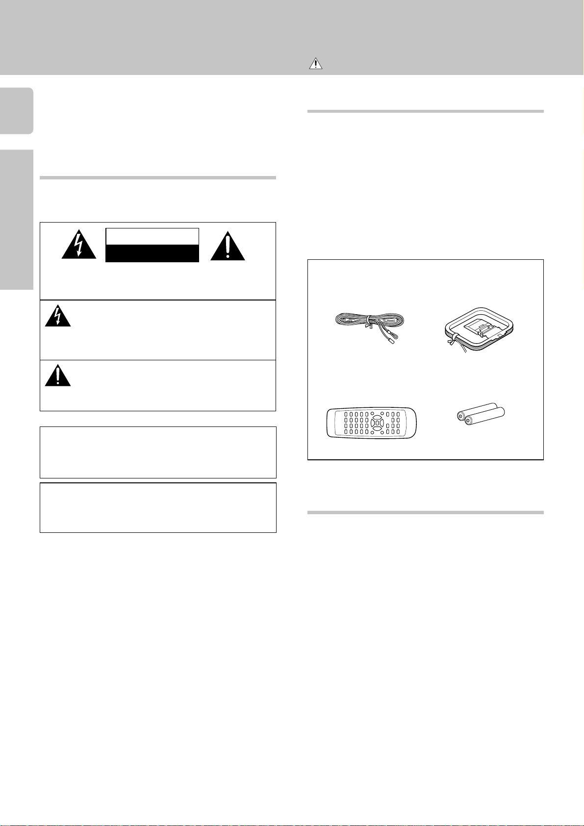
CAUTION
RISK OF ELECTRIC SHOCK
DO NOT OPEN
CAUTION: TO REDUCE THE RISK OF ELECTRIC SHOCK, DO NOT
REMOVE COVER (OR BACK). NO USER-SERVICEABLE PARTS
INSIDE, REFER SERVICING TO QUALIFIED SERVICE PERSONNEL.
THE LIGHTNING FLASH WITH ARROWHEAD SYMBOL,
WITHIN AN EQUILATERAL TRIANGLE, IS INTENDED TO
“DANGEROUS VOLTAGE” WITHIN THE PRODUCT’S ENCLOSURE THAT MAY BE OF SUFFICIENT MAGNITUDE TO CONSTI-
Operations
TUTE A RISK OF ELECTRIC SHOCK TO PERSONS.
NANCE (SERVICING) INSTRUCTIONS IN THE LITERATURE ACCOMPANYING THE APPLIANCE.
ALERT THE USER TO THE PRESENCE OF UNINSULATED
THE EXCLAMATION POINT WITHIN AN EQUILATERAL
TRIANGLE IS INTENDED TO ALERT THE USER TO THE
PRESENCE OF IMPORTANT OPERATING AND MAINTE-
Unpacking
Unpack the unit carefully and make sure that all accessories
are put aside so they will not be lost.
Examine the unit for any possibility of shipping damage. If
your unit is damaged or fails to operate, notify your dealer
immediately. If your unit was shipped to you directly, notify
the shipping company without delay. Only the consignee (the
person or company receiving the unit) can file a claim against
the carrier for shipping damage.
We recommend that you retain the original carton and packing materials for use should you transport or ship the unit in
the future.
Keep this manual handy for future reference.
Accessories
FM indoor antenna (1)
AM loop antenna (1)
Batteries (R06/AA) (2)Remote control unit (1)
Maintenance of the set
When the front panel or case becomes dirty, wipe with a soft,
dry cloth. Do not use thinner, benzine, alcohol, etc. for these
agents may cause discoloration.
In regard to contact cleaner
Do not use contact cleaners because it could cause a
malfunction. Be specially careful not to use contact cleaners
containing oil, for they may deform the plastic component.
How to use this manual
This manual is divided in to three sections, Preparations,
Operations, and Other.
Preparations
Shows you how to connect your audio components to the
receiver.
We’ve tried to make setting up your system as easy as
possible. However, since this receiver works with all of your
audio components, connecting the system can be fairly
complex.
Operations
Shows you how to operate the various functions available
from the receiver.
Other
Shows you additional information such as “In case of difficulty” (troubleshooting) and “Specifications.”

Getting started
Special features
MONITOR
The TAPE2/MONITOR jacks of this unit accept the connection of a cassette deck, graphic equalizer, surround processor, etc. When a 3-head cassette deck is connected to the
TAPE2/MONITOR jacks, it is possible to monitor the sound
which has just been recorded during recording.
Station preset
This unit incorporates a function for storing received stations
in preset memory with a simple operation. It is very convenient to preset the stations you like. The preset stations can
be recalled also very easily.
RDS (Radio Data System) tuner
The receiver is equipped with a RDS tuner that provides several
convenient tuning functions: RDS Auto Memory to automatically preset up to 30 stations including RDS broadcasting
different programs and ordinary FM stations; station name
display to show you the name of the current broadcast station;
and PTY Search to let you tune stations by program type.
PTY (Program TYpe) search
Lets you tune stations by specifying the type of program
you want to hear.
EON (Enhanced Other Networks) reservation
The EON function lets you monitor information on other
stations so you can receive traffic or news programs as
soon as they are broadcast, even they are broadcast on a
station different from the one you are currently listening
to. When the broadcast ends, the receiver returns to the
original station. When listening to KENWOOD source
components connected with system control cords, the
input selector on the receiver automatically switches to
the tuner when a program you desire is broadcast.
Remote controllable audio function
By connecting KENWOOD source components such as a
cassette deck and CD player through system control connection, the basic operations of these components can be controlled from the remote control unit provided with this unit. A
single remote control unit can control the entire audio system
easily.
New “TRAIT“ transistor
The new developed “TRAIT” transistor with extremely superior temperature characteristics is used in this amplifier‘s
amplification circuit. Through the use of this transistor, distortion generated because of temperature change is kept to a
minimum resulting in “pure” sound reproduction.
@
$
#
Contents
Caution : Read the pages marked carefully to ensure
safe operation.
Preparations
Before applying the power …………………………….. 2
Safety precautions ……………………………………………….. 2
Unpacking……………………………………………………………. 2
How to use this manual ………………………………………… 2
Special features……………………………………………………. 3
Setting up the system……………………………………… 4
Connecting audio components ………………………………. 4
Connecting the antennas ………………………………………. 5
Connecting the speakers ………………………………………. 5
Connecting the system control ……………………………… 6
Names and functions of parts ………………………… 7
Main unit …………………………………………………………….. 7
Remote control unit ……………………………………………… 8
Preparing the remote control …………………………………. 9
Operations
Normal playback…………………………………………… 10
Preparing for playback…………………………………………. 10
Listening to a source component …………………………. 10
Adjusting the sound ……………………………………………. 11
Recording ……………………………………………………… 12
Recording audio …………………………………………………. 12
Listening to radio broadcasts……………………….. 13
Tuning (non-RDS) radio stations …………………………… 13
Using RDS (Radio Data System) …………………………… 13
Using the DISPLAY key ………………………………………. 14
Presetting RDS stations 13
(RDS AUTO MEMORY) ……………………………………. 14
Presetting radio stations manually………………………… 15
Receiving preset stations ……………………………………. 15
Receiving preset stations in order (P.CALL)…………… 15
Tuning by program type (PTY search) …………………… 16
Reserving the desired information ……………………….. 16
Other
In case of difficulty……………………………………….. 18
Specifications ………………………………………………. 20
3
Preparations
Operations
Other
Setting up the system
Caution : Read this page carefully to ensure safe operation.
Make connections as shown below.
When connecting the related system components, be
4
sure to also refer to the instruction manuals supplied
with the components you are connecting.
Do not connect the power cord to a wall outlet until all
connections are completed.
Microcomputer malfunction
Preparations Other
If operation is not possible or an erroneous display appears, even though all connections have been made
properly, reset the microcomputer referring to “In case of
difficulty”.
CAUTION
Be sure to adhere followings. Or proper ventilation
will be blocked causing damage or fire hazard.
• Do not place any objects impairing heat radiation onto
the top of unit.
• Leave a space around the unit (from the largest outside
dimension including projection) equal or greater than,
Operations
shown below.
Top panel : 50 cm
Side panel : 10 cm
Back panel : 10 cm
*
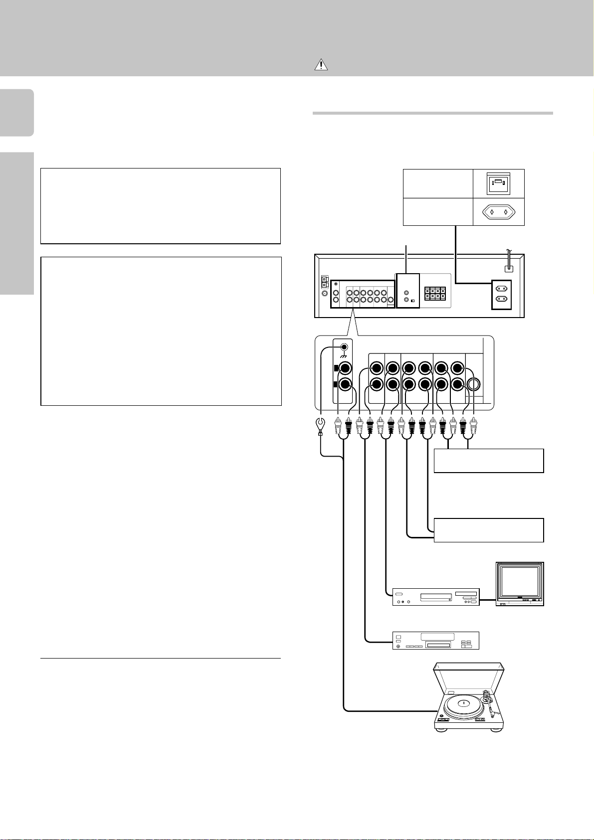
Connecting audio components
Shape of AC outlets
For U.K.
Other countries
SYSTEM CONTROL jacks
PLAY IN
L
R
PHONO
PLAY IN
AUX MD / TAPE1 TAPE2/
CD
REC OUT
PLAY IN REC OUT PLAY IN
6
To AC wall outlet
MONITOR
Notes:
1. Be sure to insert all connection cords securely. If their
connections are imperfect, the sound may not be produced or noise may interfere.
2. Be sure to remove the power cord from the AC outlet
before plugging or unplugging any connection cords. Plugging / unplugging connection cords without disconnecting
the power cord can cause malfunctions and may damage
the unit.
3. Do not connect power cords from components whose
power consumption is larger than what is indicated on the
AC outlet at the rear of this unit.
OUT
OUT
IN
Cassette deck or
graphic equalizer
OUT
Cassette deck or
MD recorder
IN
Video deck
CD player
OUT
Record player
OUT
@
Monitor TV
Setting up the system
SPEAKERS
+
—
+
R
+
—
+
L
LR
B
A
SUBWOOFER
PRE OUT
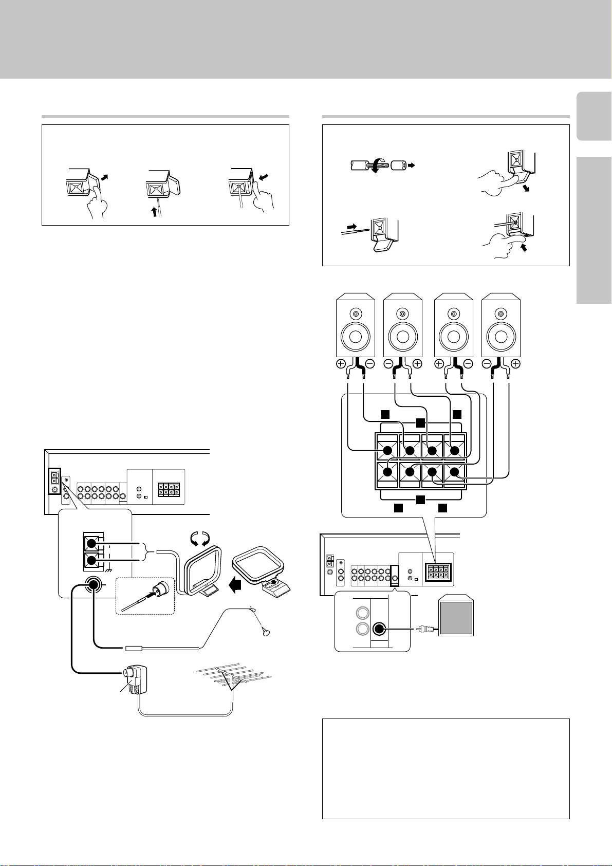
Connecting the antennas
AM Antenna terminal connections
1 Push lever.
AM loop antenna
The supplied loop antenna is for use indoors. Place it as far as
possible from the receiver, TV set, speaker cords and power
cord, and adjust the direction for best reception.
FM indoor antenna
The supplied indoor antenna is for temporary use only. For
stable signal reception we recommend using an outdoor
antenna. Disconnect the indoor antenna when you connect
one outdoors.
FM outdoor antenna
Lead the 75Ω coaxial cable connected to the FM outdoor
antenna into the room and connect it to the FM 75Ω terminal.
2 Insert cord. 3 Return lever.
Connecting the speakers
1 Strip coating.
3 Insert cord. 4 Return lever.
Front Speakers A
Right
Left
Front Speakers B
Right
2 Push lever.
Left
5
Preparations
Operations
ANTENNA
AM
GND
FM
75Ω
Use an antenna adaptor
(Commercially available)
FM indoor
antenna
Use the FRONT
SPEAKERS B
AM loop
antenna
terminals if you
want to connect a
second front
speaker system.
Other
To produce sound from
the powered subwoofer,
turn the SPEAKERS A
key on. No sound will be
FM outdoor antenna
• Never short circuit the + and – speaker cords.
Powered subwoofer
produced if only the
SPEAKERS B key is on.
• If the left and right speakers are connected inversely or the
speaker cords are connected with reversed polarity, the
sound will be unnatural with ambiguous acoustic imaging.
Be sure to connect the speakers correctly.
Speaker impedance
After confirming the speaker impedance indications printed
on the rear panel of the receiver, connect speakers with
matching impedance ratings. Using speakers with a rated
impedance other than that indicated on the rear panel of
the receiver could result in malfunctions or damage to the
speakers or receiver.
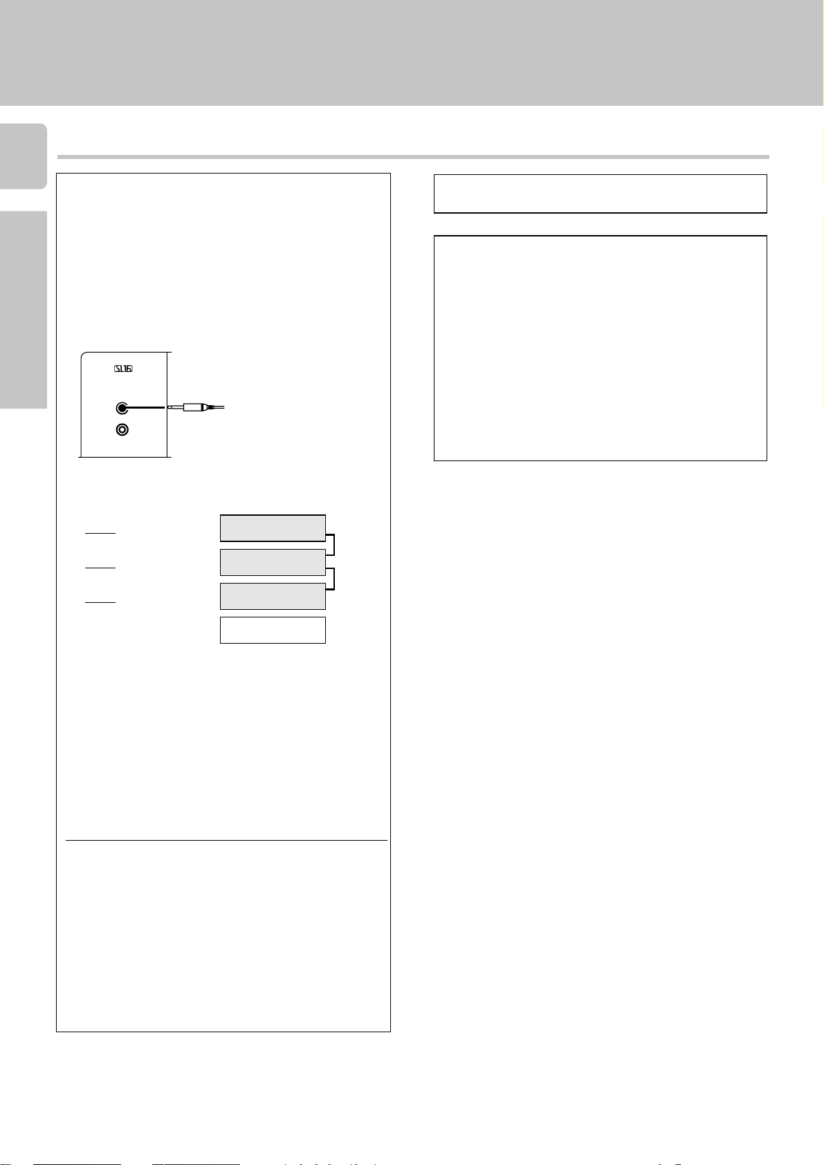
Connecting the system control
6
Connecting system control cords after connecting a
KENWOOD audio component system lets you take
advantage of convenient system control operations.
Setting up the system
Do not connect a system control cord to a cassette
deck connected to the TAPE2/MONITOR jacks.
This unit is compatible only with the [SL-16] mode. The
system control operation is not available if the unit is
Preparations Other
connected in the [XS-8], [XS], or [XR] connection
mode.
If your component has the mode select switch, set the
connected components to the [SL16] mode.
SYSTEM CONTROL cord
EXAMPLE: [SL16] mode connections
The underlined portion represents the setting of the system
Operations
control mode.
SL16]
[
[
SL16] [XS] [XS8] [XR]
[
SL16] [XS] [XS8]
[XS]
Receiver
Cassette deck
or MD recorder
CD player
Record player
SYSTEM CONTROL operations
Remote Control
Lets you operate this unit with the system remote supplied with the receiver.
Automatic Operation
When you start playback from a source component, the
input selector on this unit switches to that component
automatically.
Synchronized Recording
Lets you synchronize recording with the start of playback
when recording from CD, MD or analog discs.
SYSTEM
CONTROL
cord
• In order to take advantage of the system control operations, the components must be connected to the correct
jacks. To use a CD player it must be connected to the CD
jacks. To use a cassette deck (or MD recorder) it must be
connected to the MD/TAPE jacks. When using more than
one CD player (etc.) only the one connected to the
specified jacks may be connected for system control.
• Some CD players and cassette decks are not compatible
with the [SL16] system control mode.
• Some MD players are not system control compatible.
You cannot make system control connections to this
kind of equipment.
Notes
1. [SL16] equipment cannot be combined with [XR], [XS],
and [XS8] equipment for system operations. If your
equipment consists of this kind of combination, please do
not connect any system control cords. Even without
system control cords, normal operations can be carried
out without effecting performance.
2. Do not connect system control cords to any components
other than those specified by KENWOOD. It may cause
a malfunction and damage your equipment.
3. Be sure the system control plugs are inserted all the way
in to the system control terminals.
Loading…
- About
- Blog
- Projects
- Help
-
Donate
Donate icon
An illustration of a heart shape - Contact
- Jobs
- Volunteer
- People
Bookreader Item Preview
texts
Kenwood KRF-A4030 user manual
- Addeddate
- 2020-08-16 03:59:47
- Identifier
- manualsbase-id-428643
- Identifier-ark
- ark:/13960/t70w7nx09
- Ocr
- ABBYY FineReader 11.0 (Extended OCR)
- Ppi
- 300
- Scanner
- Internet Archive Python library 1.9.4
comment
Reviews
There are no reviews yet. Be the first one to
write a review.
104
Views
DOWNLOAD OPTIONS
Temporarily Unavailable
DAISY
For users with print-disabilities
Uploaded by
chris85
on
SIMILAR ITEMS (based on metadata)
FAQ: Types of Manuals and Their Contents
Kenwood KRF-A4030 Manuals come in various types, each serving a specific purpose to help users effectively operate and maintain their devices. Here are the common types of Kenwood KRF-A4030 User Guides and the information they typically include:
- User Manuals: Provide comprehensive instructions on how to use the device, including setup, features, and operation. They often include troubleshooting tips, safety information, and maintenance guidelines.
- Service Instructions: Designed for technicians and repair professionals, these manuals offer detailed information on diagnosing and repairing issues with the device. They include schematics, parts lists, and step-by-step repair procedures.
- Installation Guides: Focus on the installation process of the device, providing detailed instructions and diagrams for proper setup. They are essential for ensuring the device is installed correctly and safely.
- Maintenance Manuals: Provide guidance on routine maintenance tasks to keep the device in optimal condition. They cover cleaning procedures, part replacements, and regular servicing tips.
- Quick Start Guides: Offer a concise overview of the essential steps needed to get the device up and running quickly. They are ideal for users who need immediate assistance with basic setup and operation.
Each type of Kenwood KRF-A4030 instruction is designed to address specific needs, ensuring users have the necessary information to use, maintain, and repair their devices effectively.
Related Instructions for Kenwood KRF-A4030:
2
DPX-M3200BT
85
1065
213
3
KDC-M4524
Service manual KDC-M4524 (Car Receiver ePDF User Guide, #FKZ33C)
28
1086
185
6
KAC-X4D
Instruction manual Kenwood KAC-X4D User Manual (Instruction manual), @2T1375
36
962
193
7
TS-700G
Operator’s manual Kenwood Transceiver Operator’s manual (File: kenwood-ts-700g-operator-s-manual-28, Sunday 13-10-2024)
28
943
217
8
HB600 series
2
1058
159
10
MG510
Manual User Manual: Kenwood MG510 (WQAU8J, Upd.Friday 14-03-2025)
79
779
180
Receiver Devices by Other Brands:
|
Pioneer DV-210K-K Service Manual Pioneer DVD Player Service manual (File: pioneer-dv-210k-k-service-manual-70, 01.11.2024) ORDER NO. 01 Nov 2024 | 70 |
|
|
Pioneer AVH-X7800BT Owner’s Manual AVH-X7800BT Owner’s manual — 7RT38H Owner’s Manual 07 May 2025 | 204 |
|
|
Pioneer MVH-AV290BT Quick Start Manual MVH-AV290BT Quick start manual — 853L7U Quick start guide 03 May 2025 | 32 |
|
|
Shinybow USA SB-6335R4 Instruction Manual SB-6335R4 Instruction manual — 4KGNE1 SB-6335R4 11 Mar 2025 | 12 |
Categories:
Cd receiver
Navigation system
Kitchen machine
Built-in hob
Cooker
Car audio