

Default Login Details
User’s Guide
GS1200 Series
GS1200-5/GS1200-5HP v2/GS1200-8/GS1200-8HP v2
5-Port / 8-Port Web Managed (PoE) Gigabit Switch
Copyright © 2017 Zyxel Communications Corporation
LAN IP Address http://192.168.1.3
Password 1234
Version 1.00 Edition 1, 12/2017

GS1200 Series User’s Guide
2
IMPORTANT!
READ CAREFULLY BEFORE USE.
KEEP THIS GUIDE FOR FUTURE REFERENCE.
This is a User’s Guide for a series of products. Not all products support all firmware features. Screenshots
and graphics in this book may differ slightly from your product due to differences in your product
firmware or your computer operating system. Every effort has been made to ensure that the information
in this manual is accurate.
Related Documentation
•Quick Start Guide
The Quick Start Guide shows how to connect the Switch and access the Web Configurator.
•More Information
Go to support.zyxel.com to find other information on the Switch.
Document Conventions
GS1200 Series User’s Guide
3
Document Conventions
Warnings and Notes
These are how warnings and notes are shown in this guide.
Warnings tell you about things that could harm you or your device.
Note: Notes tell you other important information (for example, other things you may need to
configure or helpful tips) or recommendations.
Syntax Conventions
• The GS1200-5, GS1200-5HP v2, GS1200-8, and GS1200-8HP v2 may be referred to as the “Switch” in this
guide.
• Product labels, screen names, field labels and field choices are all in bold font.
• A right angle bracket ( > ) within a screen name denotes a mouse click. For example, QoS > Port-
Based QoS means you first click QoS in the navigation panel, then the Port-Based QoS sub menu to
get to that screen.
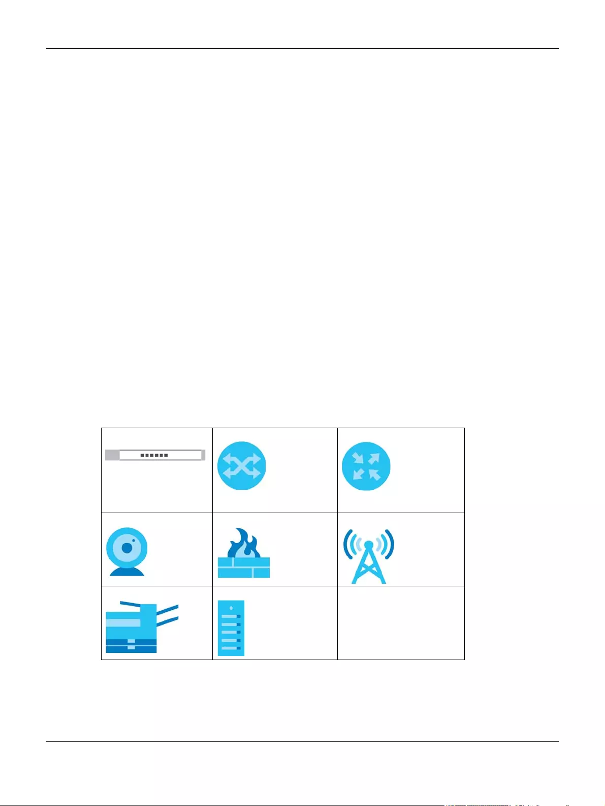
Icons Used in Figures
Figures in this user guide may use the following generic icons. The Switch icon is not an exact
representation of your device.
Switch Generic Switch Generic Router
IP Camera Firewall Cell Tower
Printer Server

Contents Overview
GS1200 Series User’s Guide
4
Contents Overview
User’s Guide ……………..……………….……………………………….…………………………………..………………….1
Getting to Know Your Switch …………………………………………………………..………………………….…………. 1
Hardware Installation …..……………………….…………………………….……………………………..………………….. 1
Hardware Panels ………………………………….…………………………….……………………………....………………… 2
The Web Configurator ……………………………………..……………………………..…………………………………….. 1
Initial Setup Example ………………………………….……………………………..…………………………………………… 6
Technical Reference ………..……………………………….……………………………………………….….……………1
System …………….……………………………..…………………………….……………………………..………………………… 1
Port ………………………………………………..…………………………….…………………………..…………………………… 4
VLAN …………………………..…………………………….……………………………..…………………………………………... 8
Link Aggregation ………………………………………………………….……………………………..……..……………….. 11
Mirroring ………………..……………………………..…………………………….……………………….………………………. 13
QoS ……………………………..…………………………….……………………………..……………….………………………… 15
IGMP Snooping ………………………………………….……………………………..………………………..……………….. 19
Management …………………………………………….……………………………..………………………..……………….. 21
Troubleshooting ……………………….…………………………….……………………………..…………..………………….. 1

Table of Contents
GS1200 Series User’s Guide
5
Table of Contents
Document Conventions ……. …. … …. ….…………………………………………… …. … …. …. ….……………………..1
Contents Overview …………………………………………….……………………………………………….……………….1
Table of Contents…………………………………………………………………………….…………………………………..1
Part I: User’s Guide…….………………………………………………………………………….1
Chapter 1
Getting to Know Your Switch ……………..……………………………………………….……………………….……….1
1.1 Introduction ………………………..…………………………….……………………………..………………………………. 1
1.2 Applications ……………………………………………….……………………………..………………..…………………... 2
1.2.1 Bridging Application ……………………………………….……………………………..……………….……….. 2
1.2.2 VLAN Application Example ………….………………….……………………………..………………………… 2
1.3 Ways to Manage the Switch …………………………………………………………………..………………..………. 3
1.4 Good Habits for Managing the Switch …………………………..……………………………..………………..… 3
Chapter 2
Hardware Installation ……………………………….……………………………………………….…………..…………….1
2.1 Installation Scenarios …….…………………………….……………………………..…………………………………….. 1
2.2 Desktop Installation Procedure …………………..……………………………..…………………………………….. 1
Chapter 3
Hardware Panels…………………………….……………………………………………….…………………..………………2
3.1 Front Panel …………………..…………………………….……………………………..……………….……………………. 2
3.2 Rear Panel ……….……………………………..…………………………….……………………………………………….... 2
3.2.1 Power Connector …………….…………………………….……………………………..………………..………. 3
3.3 LEDs …..……………………………..…………………………….……………………………..………………………………. 4
Chapter 4
The Web Configurator…………………………………………………………….……………………………….…………...1
4.1 Overview …………………………………………………………………………………..…………………………………….. 1
4.2 System Login ………….…………………………….……………………………..…………………………………………… 1
4.3 The Web Configurator Layout …..…………………………….……………………………..………………..………. 2
4.3.1 Change Your Password ……………………..……………………………..……………………………..……… 4
4.4 Switch Lockout ……………..…………………………….……………………………..………………….…………………. 4
4.5 Resetting the Switch …………..…………………………….……………………………..………………………………. 5
4.6 Logging Out of the Web Configurator ………………………………..…………………………………………... 5

Table of Contents
GS1200 Series User’s Guide
6
Chapter 5
Initial Setup Example.………..………………………………………………………………………………….………….….6
5.1 Overview …………………………………………………………………………………..…………………………………….. 6
5.1.1 Creating a VLAN …………………….…………………………….……………………………..………..………… 6
5.1.2 Setting Port VID ……………………….…………………………….……………………………..…….……………. 8
5.1.3 Power over Ethernet (PoE) Configuration ……………………………………………..………………….. 9
Part II: Technical Reference…………………………………………………………………..1
Chapter 6
System…………………….……………………………….……………………………………………….….…………..…………1
6.1 Overview …………………………………………………………………………………..…………………………………….. 1
6.2 System Screen …………………….…………………………….……………………………..………………………………. 1
Chapter 7
Port ………………………………………………………….………………………………………………..………………………..4
7.1 Overview …………………………………………………………………………………..…………………………………….. 4
7.1.1 What You Need to Know ………………………………..…………………………………………………….…. 4
7.2 Port Screen …………………..…………………………….……………………………..…………………………………….. 5
Chapter 8
VLAN……………..…………………………………………………………….………………………………………………………8
8.1 Overview …………………………………………………………………………………..…………………………………….. 8
8.1.1 What You Need to Know ………………………………..…………………………………………………….…. 8
8.2 VLAN Screen …………………………………..…………………………….……………………………...…………………. 9
Chapter 9
Link Aggregation ………. …. …. …. ………………….………….. …. …. … ….…………… … …. …. ….……..…………….11
9.1 Overview …………………………………………………………………………………..…………………………………… 11
9.2 Link Aggregation Screen ……………………………………………….……………………………..………………… 11
Chapter 10
Mirroring…………..……………….……………………………….……………………………………………………………...13
10.1 Overview ………………………………………………….……………………………..…………………………………… 13
10.2 Mirroring Screen ………………………………….……………………………..…………………………………………. 13
Chapter 11
QoS……………….…………..……………….……………………………….……………………………..…………….……….15
11.1 Overview ………………………………………………….……………………………..…………………………………… 15
11.2 What You Need to Know ……………………………………….……………………………..……………….……… 15
11.2.1 Port-Based QoS ……………………………………………………………………..…………………….………. 15

Table of Contents
GS1200 Series User’s Guide
7
11.2.2 IEEE 802.1p QoS ………..…………………………….……………………………..…………………………….. 15
11.2.3 Weighted Round Robin Scheduling (WRR) …….……………………………………………………… 16
11.3 Port-Based QoS Screen ……………………….……………………………..……………………………....………… 17
11.4 IEEE 802.1P QoS Screen ………………………………………….……………………………..………………………. 18
Chapter 12
IGMP Snooping ……………..……………….…………………………………………………………….……..…………….19
12.1 Overview ………………………………………………….……………………………..…………………………………… 19
12.2 IGMP Snooping Screen ………………….…………………………….……………………………..……….……….. 19
Chapter 13
Management ………….………………………………………………………………………………..………………….……21
13.1 Overview ………………………………………………….……………………………..…………………………………… 21
13.1.1 What You Need to Know …………………………………….……………………………..………………...21
13.2 Management Screen ……….…………………………….……………………………..…………………….………. 21
13.2.1 Firmware Upgrade Screen ………….……………………………..……………………………..…………..23
Chapter 14
Troubleshooting..……………….……………………………….………………………………………………………………..1
14.1 Power, Hardware Connections, and LEDs ….………………………………………………………………….... 1
14.2 Switch Access and Login …………………….……………………………..……………………………..……………. 2
14.3 Switch Configuration ……………………..…………………………….……………………………..………………….. 4
Appendix A Customer Support ………………………………………………………………….…………………....…. 1
Appendix B Legal Information ……………………….…………………………………………………………….……… 1
Index …………….…………………………………………………………….………………………………………………………1

8
PART I
User’s Guide

GS1200 Series User’s Guide
9
CHAPTER 1
Getting to Know Your Switch
1.1 Introduction
This chapter introduces the main features and applications of the Switch. The GS1200 Series consists of
the following models:
• GS1200-5
• GS1200-5HP v2
• GS1200-8
• GS1200-8HP v2
The Switch has 5/8 ports. You can easily connect different devices, such as computers, network storage
devices, IP cameras, print servers to your home network.
The PoE ports of the GS1200-5HP v2 and GS1200-8HP v2 support IEEE802.3at High Power over Ethernet
(PoE) and IEEE802.3af PoE standard, to provide power to IP CAM, wall mounted AP, and other devices
that may be far from a power outlet.
For an advanced user, the Switch also provides a utility like web configurator to give you an easy
configuration for VLAN, QoS, basis system management, and firmware upgrade. The Switch is compliant
with IEEE802.3az (Energy Efficient Ethernet Standard), and provides power-saving benefits without
compromising performance.
Key feature differences between Switch models are as follows. Other features are common to all
models.
Table 1 GS1200 Series Comparison Table
MODEL GS1200-5 GS1200-5HP V2 GS1200-8 GS1200-8HP V2
Total Port Number5588
10/100/1000 Mbps PoE
Ports
— Ports 1-4 — Ports 1-4
10/100/1000 Mbps
Ethernet Ports
Ports 1-5 Port 5 Ports 1-8 Ports 5-8
PoE Feature —IEEE 802.3 af PoE
IEEE 802.3at High
Power over Ethernet
(PoE)
—IEEE 802.3 af PoE
IEEE 802.3at High
Power over Ethernet
(PoE)
PoE Maximum Power — 60W PoE power
budget
— 60W PoE power
budget
Power ON/OFF Switch-v-v
802.1p QoS and Port-
Based QoS
vvvv
Chapter 1 Getting to Know Your Switch
GS1200 Series User’s Guide
10
1.2 Applications
This section shows a few examples of using the Switch in various network environments.
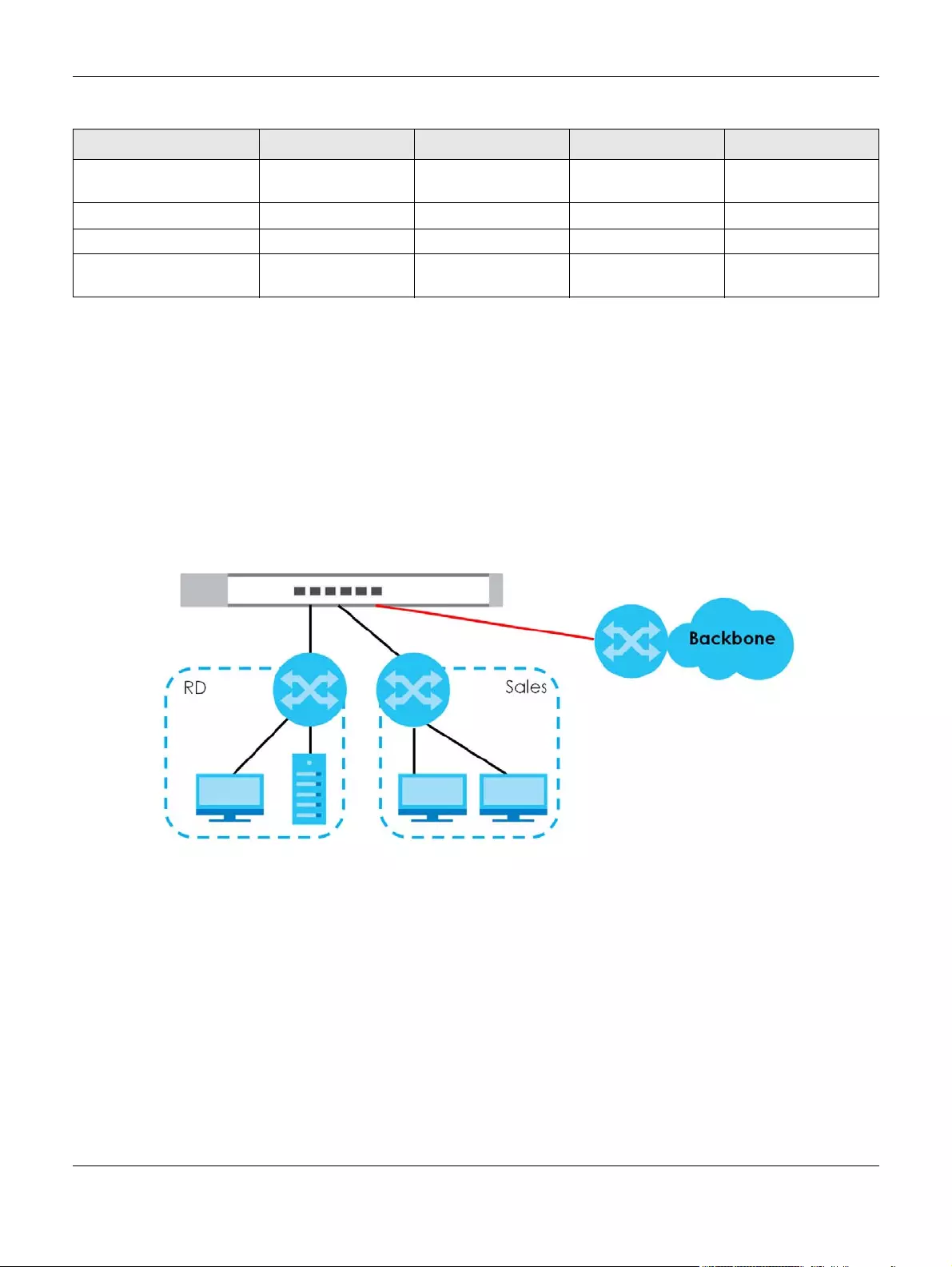
1.2.1 Bridging Application
In this example the Switch connects different company departments (RD and Sales) to the corporate
backbone. It can alleviate bandwidth contention and eliminate server and network bottlenecks. All
users that need high bandwidth can connect to high-speed department servers via the Switch.
Figure 1 Bridging Application
1.2.2 VLAN Application Example
A VLAN (Virtual Local Area Network) allows a physical network to be partitioned into multiple logical
networks. Stations on a logical network belong to one or more groups. With VLAN, a station cannot
directly talk to or hear from stations that are not in the same group(s) unless such traffic first goes through
a router.
1.2.2.1 Tag-based VLAN Example
Ports in the same VLAN group share the same frame broadcast domain, thus increasing network
performance by reducing broadcast traffic. VLAN groups can be modified at any time by adding,
moving or changing ports without any re-cabling.
IGMP Snooping v1/v2
and v3 Compatible
vvvv
Broadcast Storm Controlvvvv
Firmware Upgradevvvv
Configuration Restore
and Backup
vvvv
Table 1 GS1200 Series Comparison Table
MODEL GS1200-5 GS1200-5HP V2 GS1200-8 GS1200-8HP V2
Chapter 1 Getting to Know Your Switch
GS1200 Series User’s Guide
11
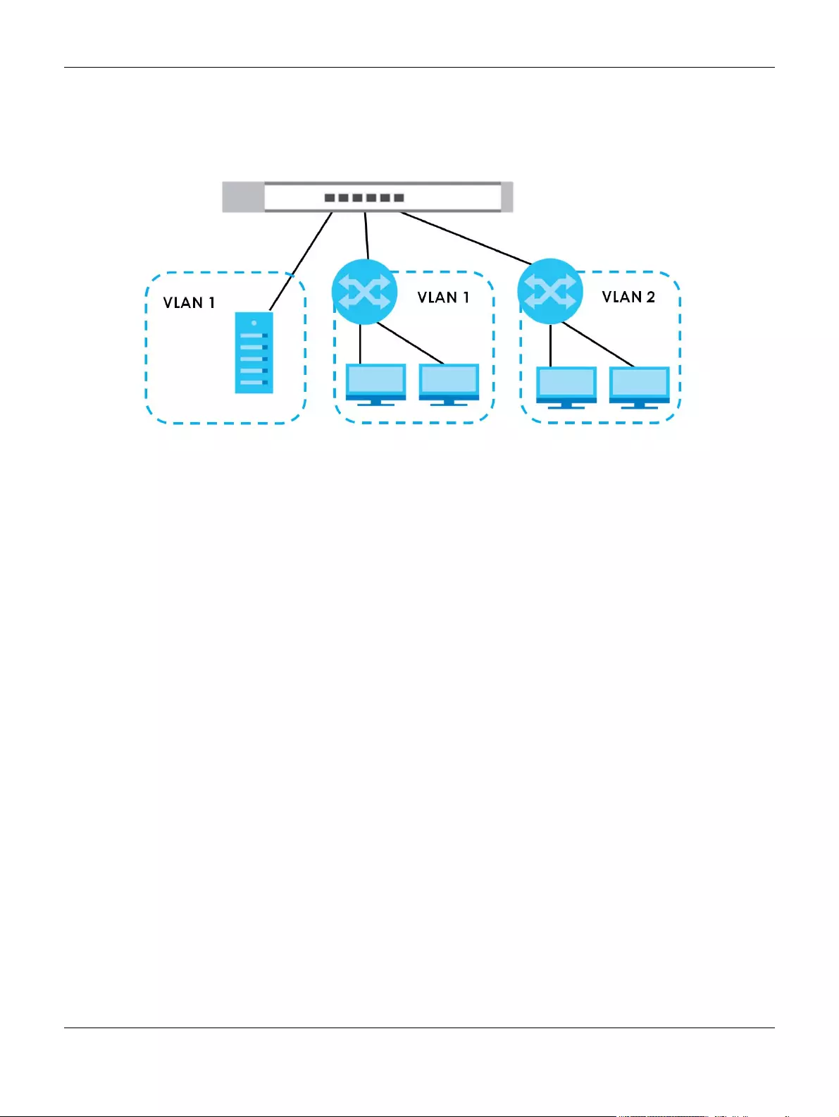
Shared resources such as a server can be used by all ports in the same VLAN as the server. In the
following figure only ports that need access to the server need to be part of VLAN1. Ports can belong to
other VLAN groups too.
Figure 2 Shared Server Using VLAN Example
1.3 Ways to Manage the Switch
Use any of the following methods to manage the Switch.
• Web Configurator. This allows easy Switch setup and management using a (supported) web browser.
See Chapter 4 on page 1.
1.4 Good Habits for Managing the Switch
Do the following things regularly to make the Switch more secure and to manage the Switch more
effectively.
• Change the password. Use a password that’s not easy to guess and that consists of different types of
characters, such as numbers and letters.
• Write down the password and put it in a safe place.
• Back up the configuration (and make sure you know how to restore it). Restoring an earlier working
configuration may be useful if the device becomes unstable or even crashes. If you forget your
password, you will have to reset the Switch to its factory default settings. If you backed up an earlier
configuration file, you would not have to totally re-configure the Switch. You could simply restore your
last configuration.

GS1200 Series User’s Guide
12
CHAPTER 1
Hardware Installation
1.1 Installation Scenarios
This chapter shows you how to install and connect the Switch.
The Switch can be placed on a desktop. Use the rubber feet in a desktop installation.
1.2 Desktop Installation Procedure
1Make sure the Switch is clean and dry.
2Set the Switch on a smooth, level surface strong enough to support the weight of the Switch and the
connected cables. Make sure there is a power outlet nearby.
3Make sure there is enough clearance around the Switch to allow air circulation and the attachment of
cables and the power cord.
Note: Make sure you are using the correct type of Ethernet cable (Category 5e, 6UTP/STP, or
better Ethernet cable).

GS1200 Series User’s Guide
13
CHAPTER 2
Hardware Panels
This chapter describes the front panel and rear panel of the Switch and shows you how to make the
hardware connections.
2.1 Front Panel
The following figures show the front panels of the Switch.
Figure 1 Front Panel: GS1200-5
Figure 2 Front Panel: GS1200-5HP v2
Figure 3 Front Panel: GS1200-8
Figure 4 Front Panel: GS1200-8HP v2
2.2 Rear Panel
The following figures show the rear panels of the Switch.
Figure 5 Rear Panel: GS1200-5

Chapter 2 Hardware Panels
GS1200 Series User’s Guide
14
Figure 6 Rear Panel: GS1200-5HP v2
Figure 7 Rear Panel: GS1200-8
Figure 8 Rear Panel: GS1200-8HP v2
2.2.1 Power Connector
Note: Make sure you are using the correct power source as shown on the panel.
To connect power to the Switch, insert the female end of the power cord to the AC power receptacle
on the rear panel. Connect the other end of the supplied power cord to a power outlet. Make sure that
no objects obstruct the airflow.

Chapter 2 Hardware Panels
GS1200 Series User’s Guide
15
2.3 LEDs
After you connect the power to the Switch, view the LEDs to ensure proper functioning of the Switch
and as an aid in troubleshooting.
Table 1 LED Descriptions
LED COLOR STATUS DESCRIPTION
PWR/SYS Green On The system power is on.
Blinking The system is starting up.
Off The system power is off.
LINK/ACT Amber (10/100
Mbps)
Green (1000
Mbps)
On The port has a successful 10/100 Mbps or 1000 Mbps connection.
Blinking The system is transmitting data through the port.
Blinking
once a
second
If you enable Loop Detection in the Port screen, the port in a loop
state will blink fast.
If you enable Loop Prevention in the Port screen, all ports will blink
fast. Later, the port in a loop state will be off. If a loop happens
on two ports, all ports will blink fast. Later, the higher-numbered
port will be off.
Off The port is disconnected or disabled.
If you enable Loop Prevention in the Port screen, and a loop
happens on two ports, the higher-numbered port will be off.
PoE
(GS1200-5HP
v2 & GS1200-
8HP v2)
Green On PoE is enabled and power is supplied to the connected PoE-
enabled device.
Off PoE is disabled or power is not being supplied.
PoE Max
(GS1200-5HP
v2 & GS1200-
8HP v2)
Amber On More than 50W has been supplied to the PoE-enabled devices,
and the PoE power output is approaching the power budget.
Off Less than 50W has been supplied to the PoE-enabled devices.
GS1200 Series User’s Guide
16
CHAPTER 1
The Web Configurator
1.1 Overview
This section introduces the configuration and functions of the web configurator.
The web configurator is an HTML-based management interface that allows easy Switch setup and
management via Internet browser. Use Internet Explorer 10.0 and later versions, Mozilla Firefox 46.0.1 and
later versions, or Google Chrome 50.0 and later versions. The recommended screen resolution is 1024 by
768 pixels.
In order to use the web configurator you need to allow:
• Web browser pop-up windows from your device.
• JavaScript (enabled by default).
• Java permissions (enabled by default).
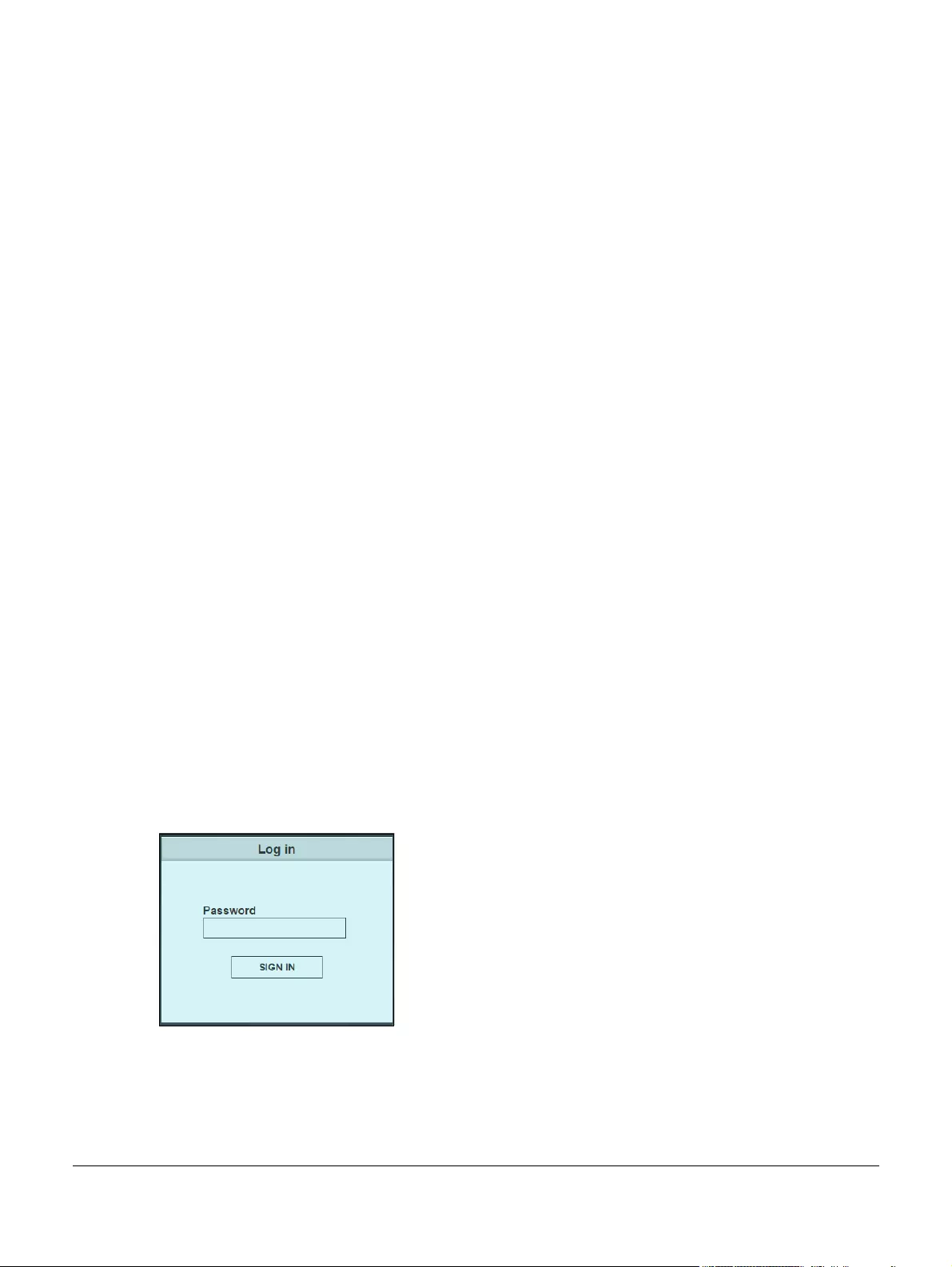
1.2 System Login
1Start your web browser.
2Type “http://” and the IP address of the Switch (for example, the default management IP address is
192.168.1.3) in the Location or Address field. Press [ENTER]. Your computer must be in the same subnet in
order to access this website address.
3The login screen appears. The default password is 1234.
Figure 1 Web Configurator: Login
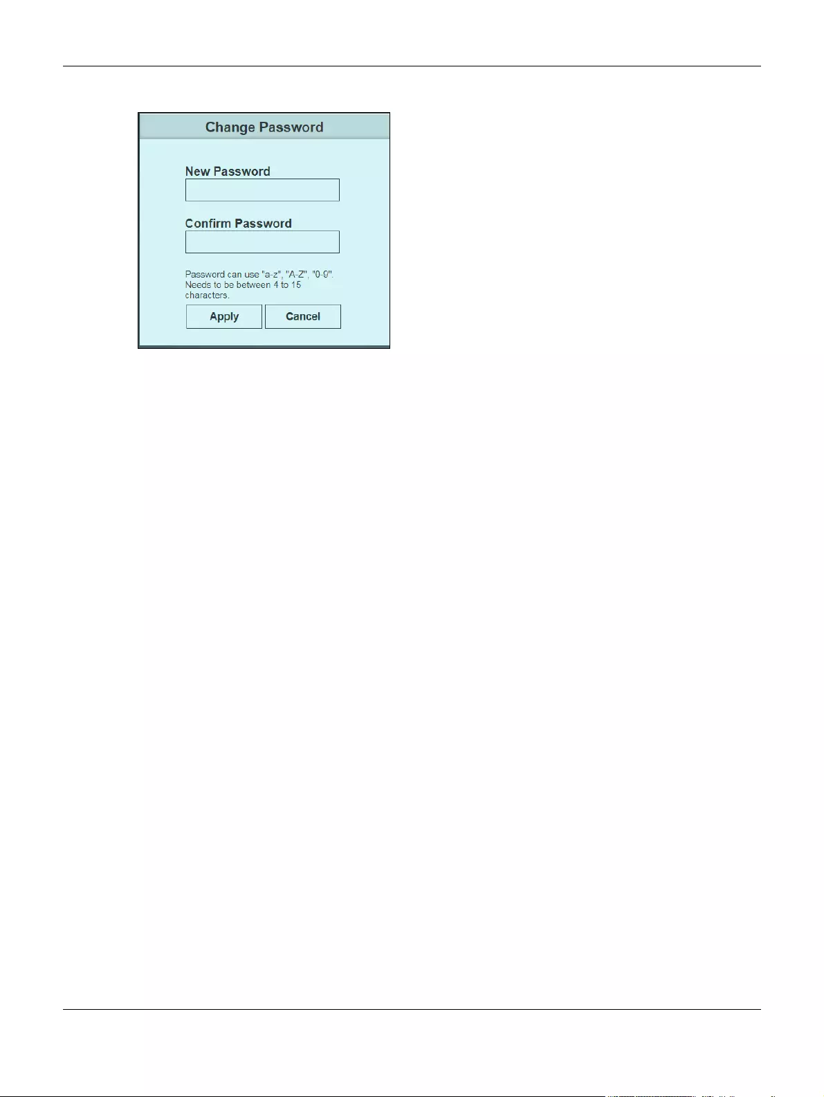
4The following screen displays if you log into the Switch for the first time. Enter a new password, retype it to
confirm and click Apply to view the first web configurator screen. Note that you can enter the default
password 1234 again, if you don’t want to change your password.
Chapter 1 The Web Configurator
GS1200 Series User’s Guide
17
Figure 2 Web Configurator: Login
1.3 The Web Configurator Layout
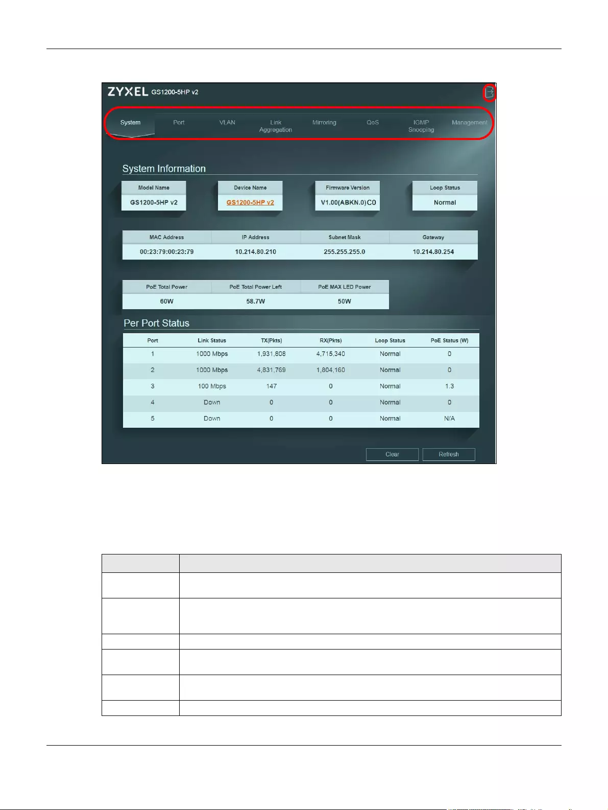
The System screen is the first screen that displays when you access the web configurator.
This guide uses GS1200-5HP v2 screens as an example. The screens may vary slightly for different models.
The following figure shows the navigating components of a web configurator screen.
Chapter 1 The Web Configurator
GS1200 Series User’s Guide
18
Figure 3 Web Configurator Layout
A — Click the menu items to open the screen in the main window.
B — Click this link to log out of the web configurator.
The following table describes the links in the navigation panel.
Table 1 Navigation Panel Links
LINK DESCRIPTION
System This link takes you to a screen that displays general system information, PoE status, and
individual port statistics.
Port This link takes you to a screen to enable Broadcast Storm Control and Loop Prevention/Loop
Detection. You can also configure advanced settings, such as transmission speed, flow control,
and PoE on a port.
VLAN This link takes you to a screen where you can configure VLAN settings.
Link Aggregation This link takes you to screens where you can logically aggregate physical links to form one
logical and higher-bandwidth link.
Mirroring This link takes you to a screen where you can copy traffic from one port or ports to another port
so that you can examine the traffic from the first port without interference.
QoS This link takes you to a screen where you can configure port-based or IEEE 802.1p QoS.
Chapter 1 The Web Configurator
GS1200 Series User’s Guide
19
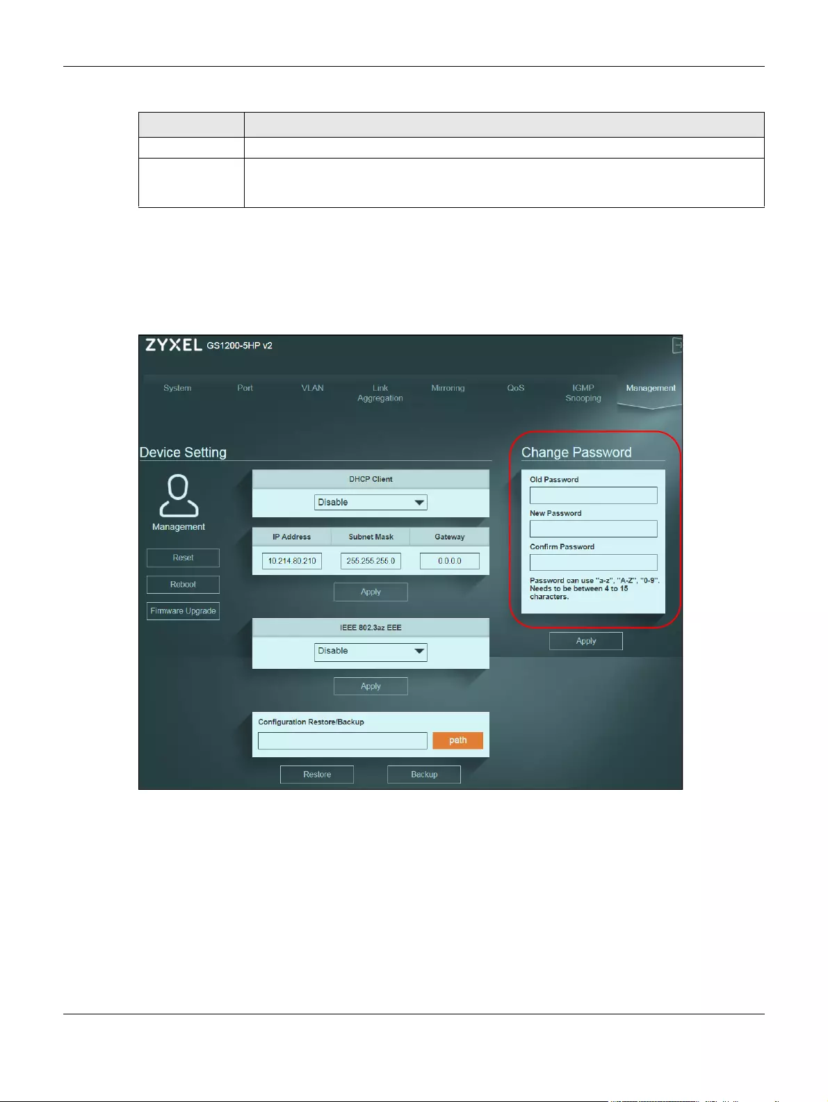
1.3.1 Change Your Password
After you log in for the first time, it is recommended you change the default administrator password.
Click Management to display the next screen to change your login password.
Figure 4 Change Administrator Login Password
1.4 Switch Lockout
You could block yourself (and all others) from managing the Switch if you do one of the following:
1Remove all ports from the management VLAN (default is VLAN 1).
2Forget the password and/or IP address.
IGMP Snooping This link takes you to a screen where you can configure IGMP snooping.
Management This link takes you to screens where you can change the system login password, perform
firmware upgrade and configuration file maintenance as well as reboot the system. You can
also configure the IP address and subnet mask.
Table 1 Navigation Panel Links (continued)
LINK DESCRIPTION

Chapter 1 The Web Configurator
GS1200 Series User’s Guide
20
3You forgot to log out of the Switch from a computer before logging in again on another computer.
Note: Be careful not to lock yourself and others out of the Switch.
1.5 Resetting the Switch
If you forget the administrator password or cannot access the Web Configurator, you will need to use
the Reset button at the front panel of the device to reset the Switch back to the factory defaults.
This means that you will lose all configurations that you had previously and the password will be reset to
“1234”. IP address will also be reset to 192.168.1.3
1Make sure the PWR/SYS LED is on (not blinking).
2To set the device back to the factory default settings, press the Reset button for ten seconds or until the
PWR/SYS LED begins to blink and then release it. When the PWR/SYS LED begins to blink, the defaults
have been restored and the device restarts.
1.6 Logging Out of the Web Configurator
Click the Logout icon in a screen to exit the web configurator. You have to log in with your password
again after you log out. This is recommended after you finish a management session for security reasons.

GS1200 Series User’s Guide
21
CHAPTER 2
Initial Setup Example
2.1 Overview
This chapter shows how to set up the Switch for an example network.
The following lists the configuration steps for the initial setup:
•Creating a VLAN
•Setting Port VID
•Power over Ethernet (PoE) Configuration
2.1.1 Creating a VLAN
VLANs confine broadcast frames to the VLAN group in which the port(s) belongs. You can create a
VLAN group with fixed port members to do this.
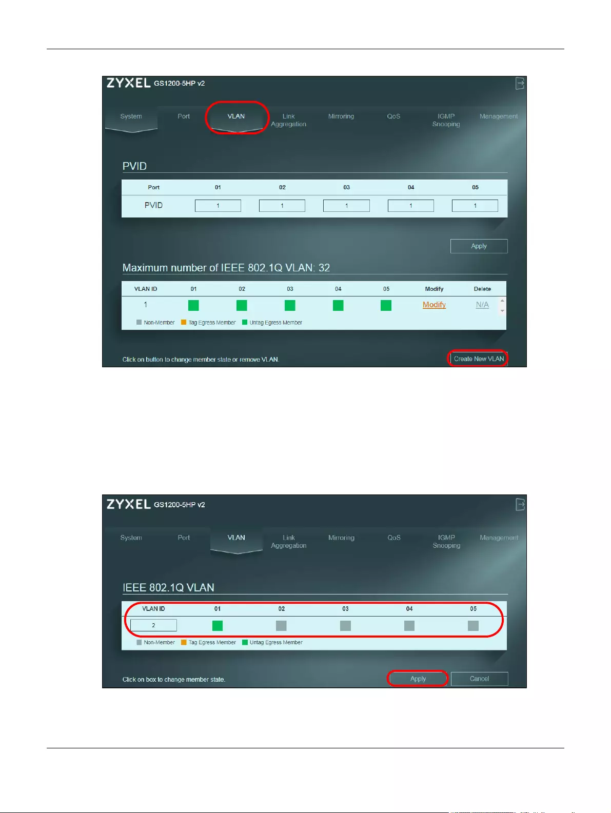
In this example, you want to configure port 1 as a member of VLAN 2.
Figure 5 Initial Setup Network Example: VLAN
1Click VLAN in the navigation panel and click the Create New VLAN button.
Chapter 2 Initial Setup Example
GS1200 Series User’s Guide
22
2Enter 2 in the VLAN ID field for the VLAN2 network.
3Since the VLAN2 network is connected to port 1 on the Switch, configure port 1 to be a permanent
member of the VLAN. To ensure that VLAN-unaware devices (such as computers and hubs) can receive
frames properly, set the port’s box color to green to set the Switch to remove VLAN tags before sending.
4Change the box color of other ports to gray.
5Click Apply to save the settings.
Chapter 2 Initial Setup Example
GS1200 Series User’s Guide
23
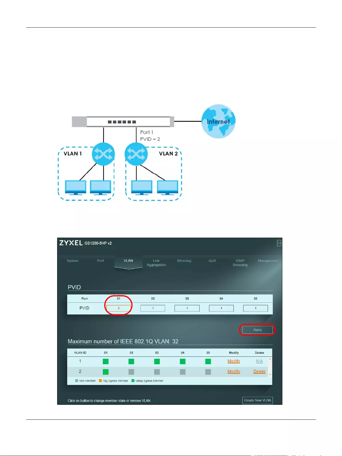
2.1.2 Setting Port VID
Use PVID to add a tag to incoming untagged frames received on that port so that the frames are
forwarded to the VLAN group that the tag defines.
In the example network, configure 2 as the port VID on port 1 so that any untagged frames received on
that port get sent to VLAN 2.
Figure 6 Initial Setup Network Example: Port VID
1Click VLAN in the navigation panel.
2Enter 2 in the PVID field for port 2 and click Apply to save your changes back to the Switch.
Chapter 2 Initial Setup Example
GS1200 Series User’s Guide
24
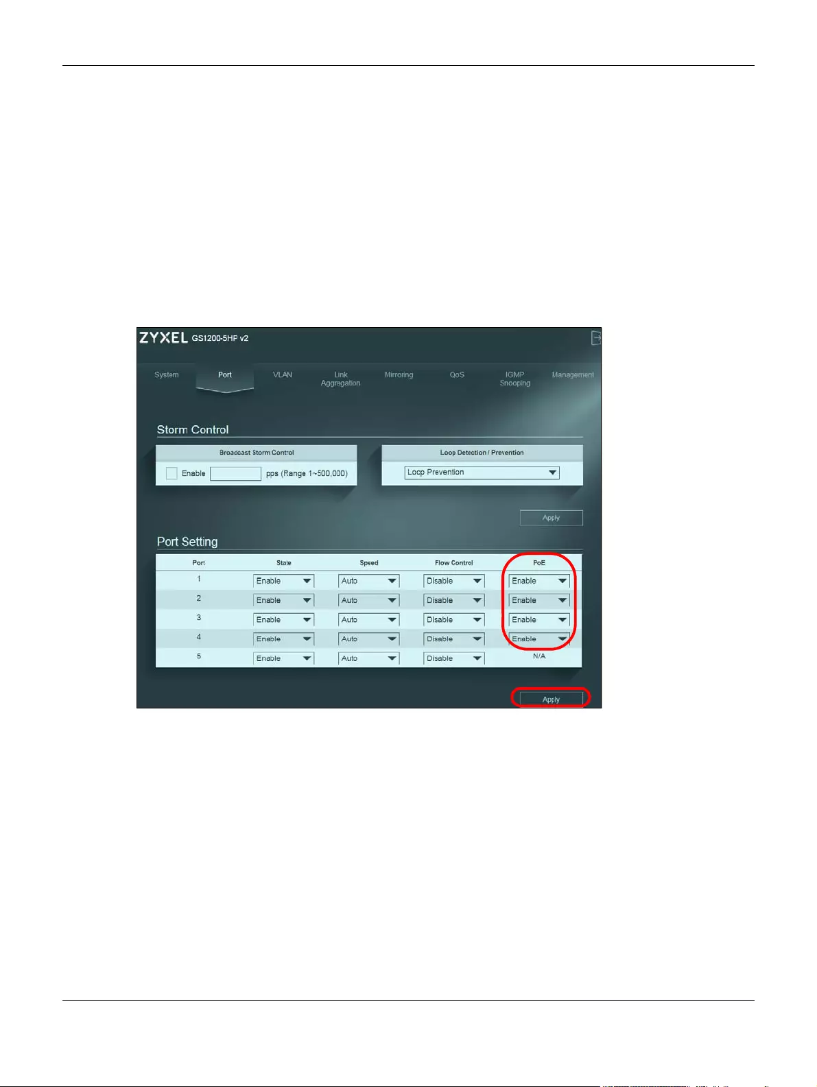
2.1.3 Power over Ethernet (PoE) Configuration
This example is for GS1200-5HP v2 and GS1200-8HP v2.
See Figure 21 on page 5 for an example of using PoE to power devices.
Before connecting devices that require PoE to the PoE ports, PD (Powered Devices), you must enable
PoE on those ports.
1Click Port in the navigation panel.
2Go to Port Setting, select Enable or Disable for ports that will supply power to PDs in the PoE field, and
click Apply to save your changes back to the Switch.
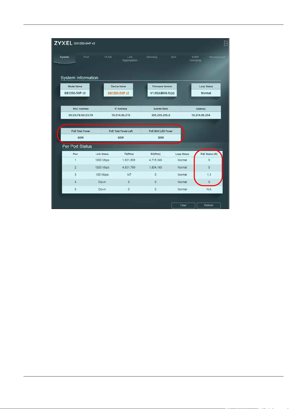
3After connecting the PDs to the PoE ports, you can go to the System screen to check the amount of
power the PDs are consuming (PoE Status), the maximum power the Switch can provide (PoE Total
Power), and so on.
See Section 6.2 on page 1 for more information about PoE .
Note: The total power the Switch can supply is 60W, and it’s shown in the PoE Total Power field.
The maximum power a PoE port can supply is 30W.
Note: The Switch allocates power to PDs in the order that they were connected.
Note: When the total power requested by the PDs exceeds the total PoE power budget on
the Switch, the last PD connected to the Switch won’t be powered up.
Chapter 2 Initial Setup Example
GS1200 Series User’s Guide
25

26
PART I
Technical Reference
GS1200 Series User’s Guide
27
CHAPTER 1
System
1.1 Overview
This chapter describes the screens for system status, and port details.
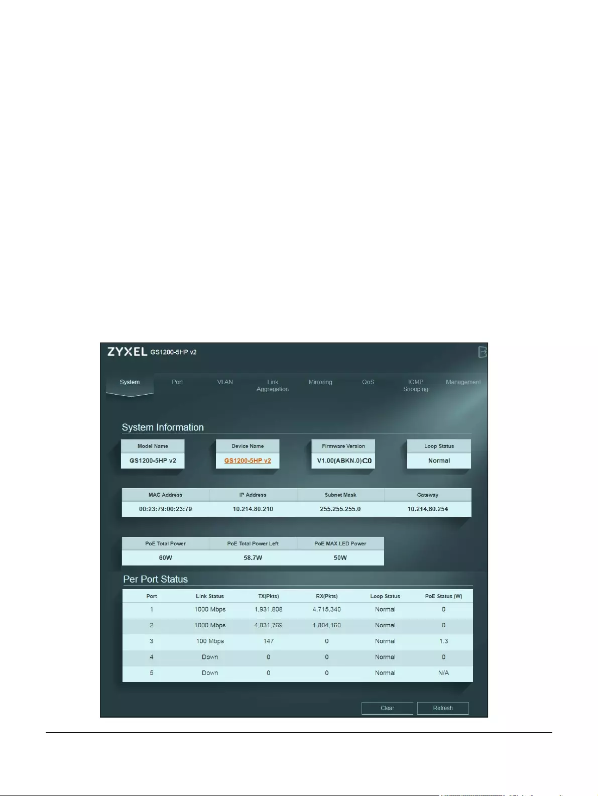
1.2 System Screen
The System screen displays when you log into the Switch or click System at the top of the web
configurator. The System screen displays the Switch’s general device information, PoE status, and the
port statistics.
Figure 1 System
Chapter 1 System
GS1200 Series User’s Guide
28
The following table describes the labels in this screen.
Table 1 System
LABEL DESCRIPTION
System Information
Model Name This field displays the model name of this Switch.
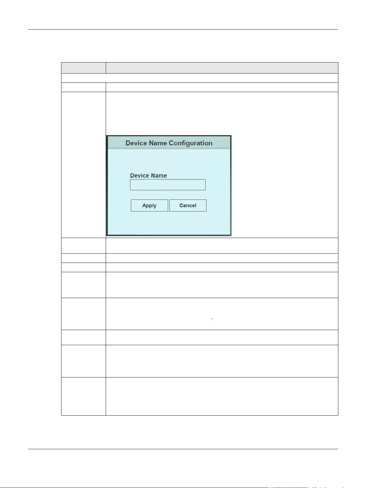
Device Name This field displays the name used to identify the Switch on any network.
The device name is a link that you can click to open a screen where you can change the
name. Enter a descriptive name of up to 14 characters. Also, spaces and the following special
characters listed in the brackets [«`<>^$|&;\/:*?’] are not allowed.
Note: You must enter a descriptive name to identify the Switch.
Firmware
Version
This field displays the version number and date of the firmware the Switch is currently running.
Loop Status This field displays whether the Switch is in a loop state.
MAC Address This field displays the MAC addresses of the Switch.
IP Address The Switch needs an IP address for it to be managed over the network. The factory default IP
address is 192.168.1.3.
This field displays the Switch’s current IPv4 address.
Subnet Mask The subnet mask specifies the network number portion of an IP address. The factory default
subnet mask is 255.255.255.0.
This field displays the Switch’s subnet mask. The subnet mask is a link that you can click to open
a screen where you can change the IP address and subnet mask.
Gateway The gateway is a router or switch on the same network segment as the device’s LAN or WAN
port. The gateway helps forward packets to their destinations.
PoE Total Power
(GS1200-5HP v2
& GS1200-8HP
v2)
This field displays the total power the Switch can provide to the connected PoE-enabled
devices on the PoE ports.
PoE Total Power
Left
(GS1200-5HP v2
& GS1200-8HP
v2)
This field displays the amount of power the Switch can still provide for PoE.

Chapter 1 System
GS1200 Series User’s Guide
29
PoE MAX LED
Power
(GS1200-5HP v2
& GS1200-8HP
v2)
This field displays the point when the PoE MAX LED will turn on, indicating the Switch is reaching
its maximum power.
When the total power requested by the PoE-enabled devices exceeds the total PoE power
budget on the Switch, the last PoE-enabled device connected to the Switch won’t be powered
up.
For example, the first PoE-enabled device connected to port 1 requires 20W, the second one
connected to port 2 requires 20W, and the third one connected to port 3 requires 25W. In this
case, the total power consumption is 65W which exceeds the maximum power the Switch can
supply. Therefore, the third PoE-enabled device won’t be powered up as it was connected last.
Per Port Status
Port This identifies the Ethernet port on the Switch.
Link status This field displays the current status or speed (either 10 Mbps, 100 Mbps or 1000 Mbps) of each
port.
TX (Pkts) This field shows the number of transmitted frames on this port.
RX (Pkts) This field shows the number of received frames on this port.
Loop Status It displays Loop when the Switch detects a loop on the port. Otherwise, it displays Normal.
PoE Status (W)
(GS1200-5HP v2
& GS1200-8HP
v2)
This field displays the amount of power the Switch is currently supplying to the PoE-enabled
device connected to the port.
Clear Click this button to clear the statistics in the TX(Pkts) and RX(Pkts) fields.
Refresh Click this button to update the information in this screen.
Table 1 System (continued)
LABEL DESCRIPTION
GS1200 Series User’s Guide
30
CHAPTER 2
Port
2.1 Overview
This chapter introduces and shows you how to configure the broadcast storm control feature and use
loop prevention or loop detection to prevent loops in your network. In addition, you can configure
transmission speed, flow control, and PoE on a port.
2.1.1 What You Need to Know
Read this section to know more about Loop Detection, Loop Prevention, broadcast storm control, and
PoE.
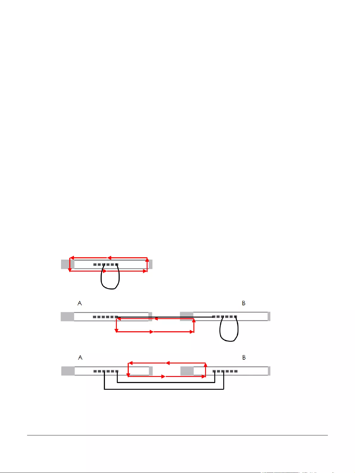
2.1.1.1 Loop Detection and Loop Prevention
A switch loop happens if there is more than one connection between two ports on the same switch or
between 2 switches connected together. If this happens, broadcasts are continually rebroadcast and
could flood the network. You must break the loop by stopping multiple paths between two switch ports.
Figure 2 Our Switch Has Two Ports Connected with Same Cable
Figure 3 Connected Switch Has Two Ports Connected with Same Cable
Figure 4 Two Connections between Switches without Spanning Tree Protocol (STP)
Loop Detection allows the Switch to discover a loop if it happens, and create a log. Loop Prevention
allows the Switch to shut down a port automatically if it discover a loop on that port. See Section 3.3 on
page 4 for more information about LEDs.
Chapter 2 Port
GS1200 Series User’s Guide
31
2.1.1.2 Broadcast Storm Control
Broadcast storm control limits the number of broadcast packets the Switch receives per second on the
ports. When the maximum number of allowable broadcast packets is reached per second, the
subsequent packets are discarded. Enable this feature to reduce broadcast packets in your network.
You can specify limits on each port.
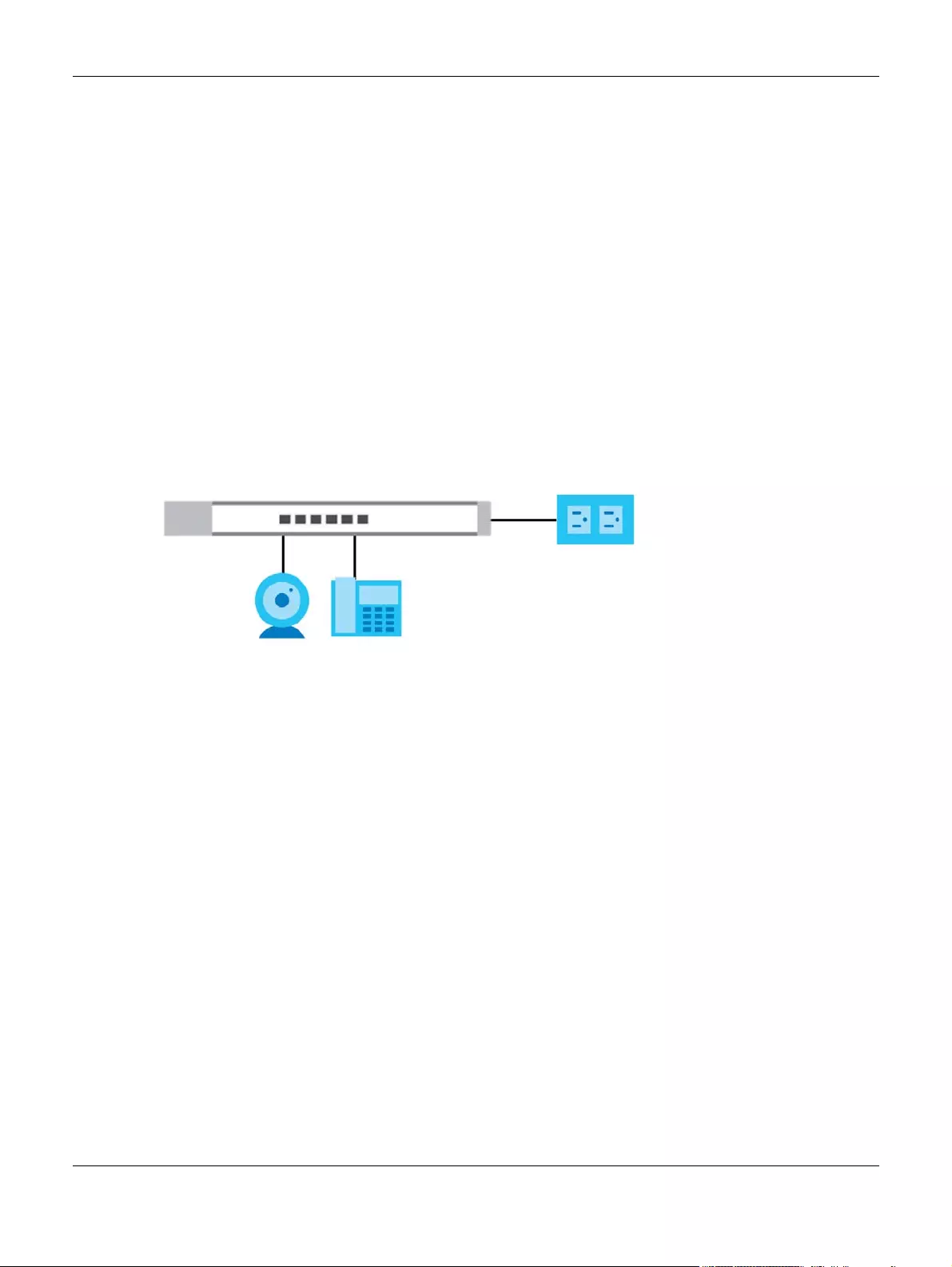
2.1.1.3 PoE (GS1200-5HP v2 & GS1200-8HP v2)
The Switch supports both the IEEE 802.3af Power over Ethernet (PoE) and IEEE 802.3at High Power over
Ethernet (PoE) standards. A PoE-enabled switch is a Power Sourcing Equipment (PSE), because it
provides a source of power via its Ethernet ports. A powered device (PD) is a device such as an access
point, IP phone, or IP camera, that receives PoE (Power over Ethernet) power from a PSE through its
Ethernet port.
In the figure below, the IP camera and IP phone are PDs getting their power directly from the Switch PSE.
Aside from minimizing the need for cables and wires, PoE removes the hassle of trying to find a nearby
electric outlet to power up devices.
Figure 5 Powered Device Example
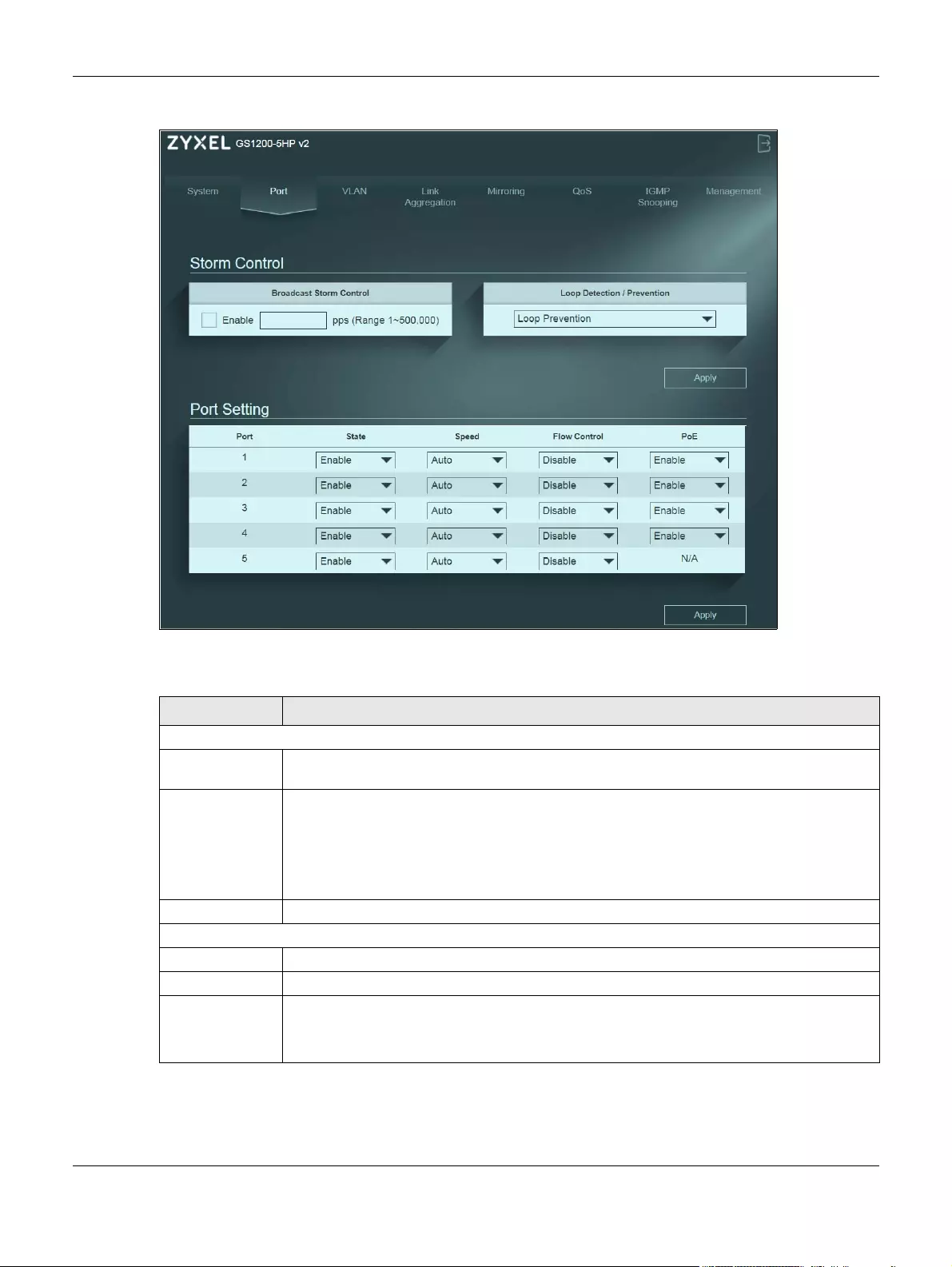
2.2 Port Screen
Click Port in the navigation panel to open the following screen.
Chapter 2 Port
GS1200 Series User’s Guide
32
Figure 6 Port
The following table describes the labels in this screen.
Table 2 Port
LABEL DESCRIPTION
Storm Control
Broadcast Storm
Control
Enable traffic storm control on the Switch by specifying how many broadcast packets a port
receives per second.
Loop Detection /
Prevention
Select Loop Detection to allow the Switch to detect a loop on the port. The port becomes
active when the loop disappears.
Select Loop Prevention to allow the Switch to shut down a port automatically when it detects a
loop on the port.The port becomes active when the loop disappears.
Select Off to disable this feature.
Apply Click this button to save your changes to the Switch.
Port Setting
Port This identifies the Ethernet port on the Switch.
State Select Enable to enable the port or Disable to disable it.
Speed Select the speed of the Ethernet connection on this port. The choices are Auto, 10 Mbps, and
100 Mbps.
Select Auto to have the Switch obtain the connection speed of up to 1000 Mbps.

Chapter 2 Port
GS1200 Series User’s Guide
33
Flow Control A concentration of traffic on a port decreases port bandwidth and overflows buffer memory
causing packet discards and frame losses. Flow Control is used to regulate transmission of
signals to match the bandwidth of the receiving port.
The Switch uses IEEE802.3x flow control in full duplex mode and backpressure flow control in half
duplex mode.
IEEE802.3x flow control is used in full duplex mode to send a pause signal to the sending port,
causing it to temporarily stop sending signals when the receiving port memory buffers fill.
Back Pressure flow control is typically used in half duplex mode to send a “collision” signal to
the sending port (mimicking a state of packet collision) causing the sending port to temporarily
stop sending signals and resend later. Select the check box to enable it.
PoE
(GS1200-5HP v2 &
GS1200-8HP v2)
Select Enable to provide power to a PoE-enabled device connected to the port or Disable so
the port cannot receive power from the Switch.
Apply Click this button to save your changes to the Switch.
Table 2 Port (continued)
LABEL DESCRIPTION

GS1200 Series User’s Guide
34
CHAPTER 3
VLAN
3.1 Overview
This chapter shows you how to configure VLAN settings.
3.1.1 What You Need to Know
Read this section to know more about VLAN and how to configure the screens.
3.1.1.1 IEEE 802.1Q Tagged VLANs
A tagged VLAN uses an explicit tag (VLAN ID) in the MAC header to identify the VLAN membership of a
frame across bridges — they are not confined to the switch on which they were created. The VLANs can
be created statically by hand or dynamically through GVRP. The VLAN ID associates a frame with a
specific VLAN and provides the information that switches need to process the frame across the network.
A tagged frame is four bytes longer than an untagged frame and contains two bytes of TPID (Tag
Protocol Identifier, residing within the type/length field of the Ethernet frame) and two bytes of TCI (Tag
Control Information, starts after the source address field of the Ethernet frame).
The CFI (Canonical Format Indicator) is a single-bit flag, always set to zero for Ethernet switches. If a
frame received at an Ethernet port has a CFI set to 1, then that frame should not be forwarded as it is to
an untagged port. The remaining twelve bits define the VLAN ID, giving a possible maximum number of
4,096 VLANs. Note that user priority and VLAN ID are independent of each other. A frame with VID
(VLAN Identifier) of null (0) is called a priority frame, meaning that only the priority level is significant and
the default VID of the ingress port is given as the VID of the frame. Of the 4096 possible VIDs, a VID of 0 is
used to identify priority frames and value 4095 (FFF) is reserved, so the maximum possible VLAN
configurations are 4,094.
Forwarding Tagged and Untagged Frames
Each port on the Switch is capable of passing tagged or untagged frames. To forward a frame from an
802.1Q VLAN-aware switch to an 802.1Q VLAN-unaware switch, the Switch first decides where to
forward the frame and then strips off the VLAN tag. To forward a frame from an 802.1Q VLAN-unaware
switch to an 802.1Q VLAN-aware switch, the Switch first decides where to forward the frame, and then
inserts a VLAN tag reflecting the ingress port’s default VID. The default PVID is VLAN 1 for all ports, but this
can be changed.
A broadcast frame (or a multicast frame for a multicast group that is known by the system) is duplicated
only on ports that are members of the VID (except the ingress port itself), thus confining the broadcast to
a specific domain.
TPID
2 Bytes
User Priority
3 Bits
CFI
1 Bit
VLAN ID
12 bits

Chapter 3 VLAN
GS1200 Series User’s Guide
35
3.2 VLAN Screen
Use this screen to view and configure VLAN settings for the Switch. Click VLAN in the navigation panel to
open the following screen.
Note: You could block yourself (and all others) from managing the Switch if you remove all
ports from the management VLAN (VLAN 1 by default).
Note: Make sure the port through which you connect your computer and access the Switch’s
web configurator is in VLAN 1.
Figure 7 VLAN
The following table describes the labels in this screen.
Table 3 VLAN
LABEL DESCRIPTION
PVID
Port This field displays the port number.
PVID A PVID (Port VLAN ID) is a tag that adds to incoming untagged frames received on a port so
that the frames are forwarded to the VLAN group that the tag defines.
Enter a number between 1 and 4094 as the port VLAN ID.
Apply Click this button to save your PVID settings to the Switch.
Maximum
number of IEEE
802.1Q VLAN
This shows the maximum number of IEEE 802.1Q VLANs you can have on the Switch.
Chapter 3 VLAN
GS1200 Series User’s Guide
36
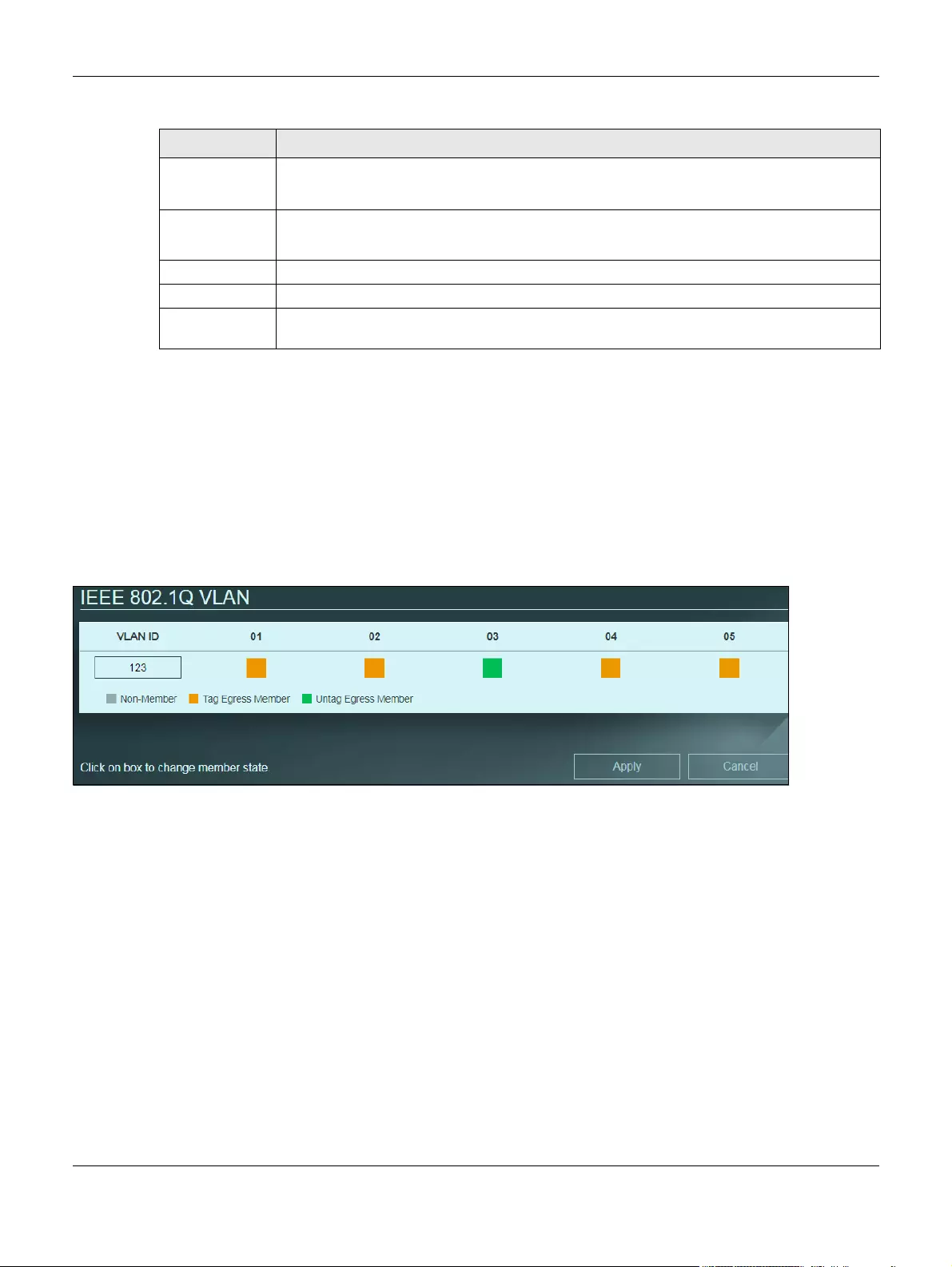
How to add ports to an IEEE 802.1Q VLAN
By default, all ports on the Switch are in VLAN 1. If you want to have a port belong to another VLAN as
well, say VLAN 123, you need to create a VLAN first, and then add the port to the VLAN.
1Click Create New VLAN and enter a VLAN ID number (123 in this example).
2Click the port’s check box to add it to the VLAN group by changing the box color to green (untagging)
or orange (tagging). Set the port’s box color to gray if the port is not a member of the VLAN group.
3Click Apply to save your changes.
VLAN ID This is the ID number of the VLAN group.
Enter a number between 1 and 4094 as the VLAN ID.
01 ~ 08
01 ~ 05
This displays the ports that are participating in a VLAN. A tagged port is orange, an untagged
port is green and ports not participating in a VLAN are gray.
Modify Click Modify to edit the VLAN settings.
Delete Click Delete to remove the VLAN group. You cannot delete the default VLAN.
Create New
VLAN
Click this button to configure a new IEEE 802.1Q VLAN for the Switch.
Table 3 VLAN (continued)
LABEL DESCRIPTION

GS1200 Series User’s Guide
37
CHAPTER 4
Link Aggregation
4.1 Overview
This chapter shows you how to logically aggregate physical links to form one logical and higher
bandwidth link.
Link aggregation is the grouping of physical ports into one logical higher-capacity link. You may want to
trunk ports if for example, it is cheaper to use multiple lower-speed links than to under-utilize a high-
speed, but more costly, single-port link.
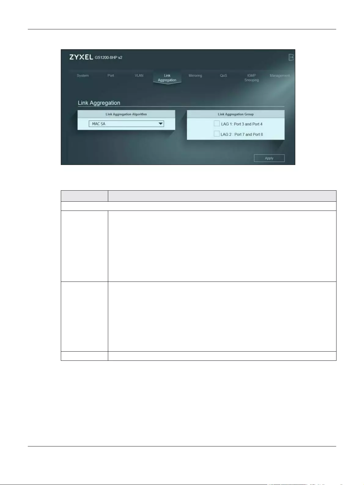
4.2 Link Aggregation Screen
Use this scree to configure static link aggregation.
Figure 8 Link Aggregation (GS1200-5 & GS1200-5HP)
Chapter 4 Link Aggregation
GS1200 Series User’s Guide
38
Figure 9 (GS1200-8 & GS1200-8HP)
The following table describes the labels in this screen.
Table 4 Link Aggregation
LABEL DESCRIPTION
Link Aggregation
Link Aggregation
Algorithm
Select the outgoing traffic distribution type. Packets from the same source and/or to the same
destination are sent over the same link within the trunk. By default, the Switch uses the MAC SA
& DA distribution type. If the Switch is behind a router, the packet’s destination or source MAC
address will be changed. In this case, set the Switch to distribute traffic based on its IP address
to make sure port trunking can work properly.
Select MAC SA to distribute traffic based on the packet’s source MAC address.
Select MAC DA to distribute traffic based on the packet’s destination MAC address.
Select MAC SA & DA to distribute traffic based on a combination of the packet’s source and
destination MAC addresses.
Link Aggregation
Group
The field identifies the default link aggregation group(s) the Switch supports.
Note: By default, the GS1200-5 and GS1200-5HP v2 have a link aggregation group
containing ports 3 and 4.
Note: By default, the GS1200-8 and GS1200-8HP v2 have two link aggregation
groups. One contains ports 3 and 4, and the other contains ports 7 and 8.
Note: Make sure the ports in a link aggregation group must have the same PVID and
VLAN ID.
Apply Click this button to save your changes to the Switch.
GS1200 Series User’s Guide
39
CHAPTER 5
Mirroring
5.1 Overview
This chapter discusses port mirroring setup screens.
Port mirroring allows you to copy a traffic flow to a monitor port (the port you copy the traffic to) in order
that you can examine the traffic from the monitor port without interference.
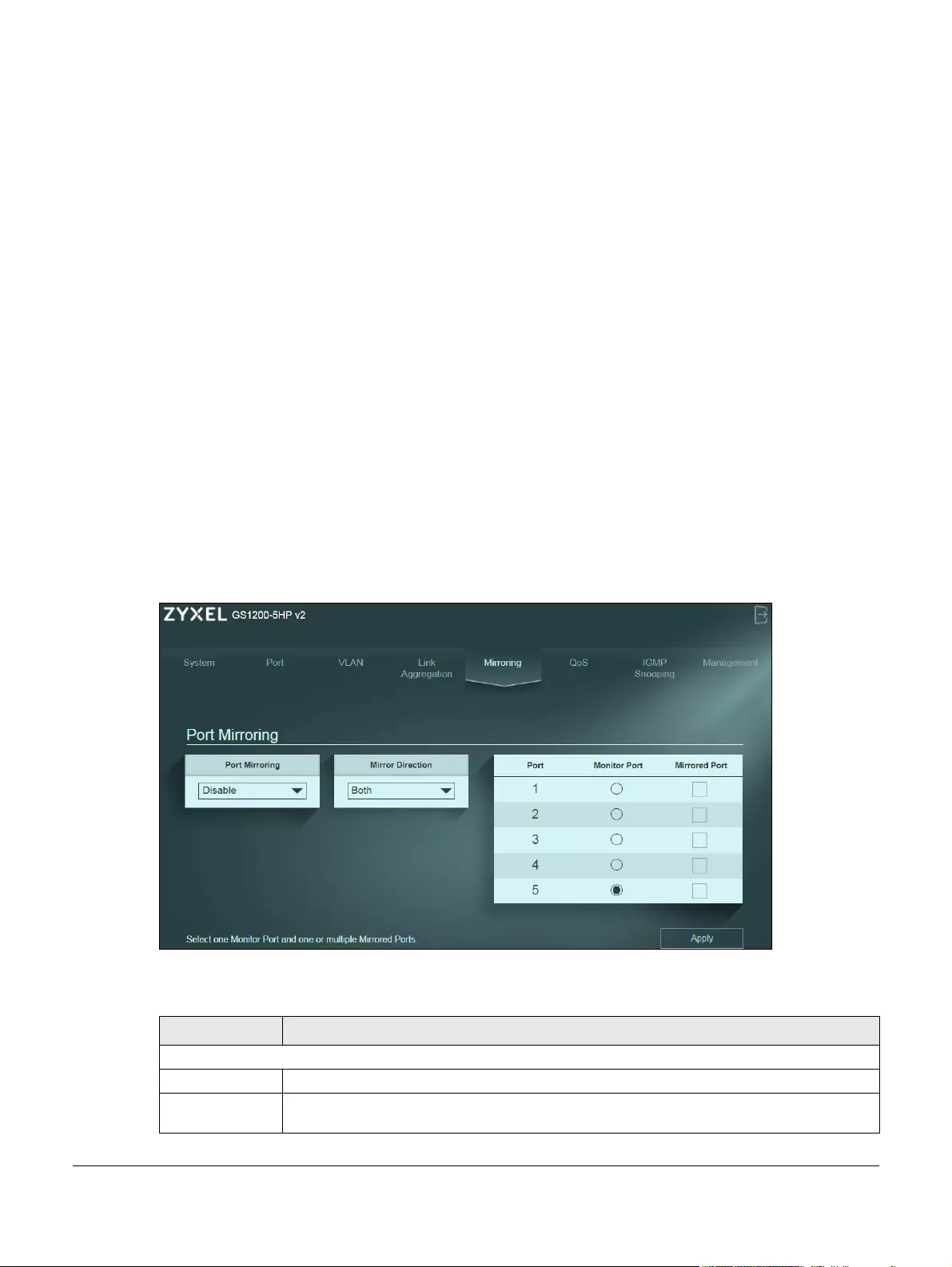
5.2 Mirroring Screen
Use this screen to select a monitor port and specify the traffic flow to be copied to the monitor port.
Note: A port can’t be the monitor port and the mirrored port at the same time.
Figure 10 Mirroring
The following table describes the labels in this screen.
Table 5 Mirroring
LABEL DESCRIPTION
Port Mirroring
Port Mirroring Select Enable to activate port mirroring on the Switch or Disable to disable the feature.
Mirror Direction Specify the direction of the traffic to mirror by selecting from the drop-down list box. Choices
are Egress (outgoing), Ingress (incoming) and Both.

Chapter 5 Mirroring
GS1200 Series User’s Guide
40
Port This field displays the port number.
Monitor Port The monitor port is the port you copy the traffic to in order to examine it in more detail without
interfering with the traffic flow on the original port(s).
Note: Select one monitor port.
Mirrored Port Select this option to mirror the traffic on a port.
Note: Select one or multiple mirrored ports.
Apply Click this button to save your changes to the Switch.
Table 5 Mirroring (continued)
LABEL DESCRIPTION

GS1200 Series User’s Guide
41
CHAPTER 6
QoS
6.1 Overview
This chapter introduces the configuration and functions of the QoS (Quality of Service) screen.
The QoS (Quality of Service) feature allows you to prioritize the flow of data passing through the Switch.
Occasionally, data might be delayed, depending on the volume of traffic and the capacity of the
equipment. Numeric and text data are usually not affected by delays, because they are reassembled
at the destination. However, when VoIP and streaming videos are reassembled, they might have some
troublesome gaps. Without QoS, all traffic data is equally likely to be dropped when the network is
congested. This can cause a reduction in network performance and make the network inadequate for
time-critical applications such as VOD (Video on Demand).
You can enable QoS to have the Switch assign each packet a priority and then queues the packet
accordingly. Packets assigned a high priority are processed more quickly than those with low priority if
there is congestion, allowing time-sensitive applications to flow more smoothly. Time-sensitive
applications include both those that require a low level of latency (delay) and a low level of jitter
(variations in delay) such as Voice over IP (VoIP) or Internet gaming, and those for which jitter alone is a
problem such as Internet radio or streaming video.
6.2 What You Need to Know
The Switch can put packets into the queues according to the port on which the packet is received or
the priority tag in the packet.
6.2.1 Port-Based QoS
The Port-Based QoS feature assigns priority to data transmitted through a particular port. When the data
arrives to a port it begins a queue. Therefore the Switch has a queue for each port. If data arrives at the
same time to all ports, ports with higher priority will be first to transmit the data received. The higher the
priority of the port, the less delays the data passing through will have.
6.2.2 IEEE 802.1p QoS
IEEE 802.1p defines a 3-bit field called PCP (Priority Code Point) within the IEEE 802.1Q VLAN tag, which is
also referred to as a CoS (Class of Service) value and indicates the frame priority level. IEEE 802.1p QoS
uses the priority value (from 0 to 7) to define up to eight traffic types. That is, each priority level defines a
Chapter 6 QoS
GS1200 Series User’s Guide
42
class of service. The table below shows the IEEE recommendations for traffic types, these may vary or be
reassigned.
Note: Frames without an explicit priority tag are treated as system traffic and assigned to
Queue0.
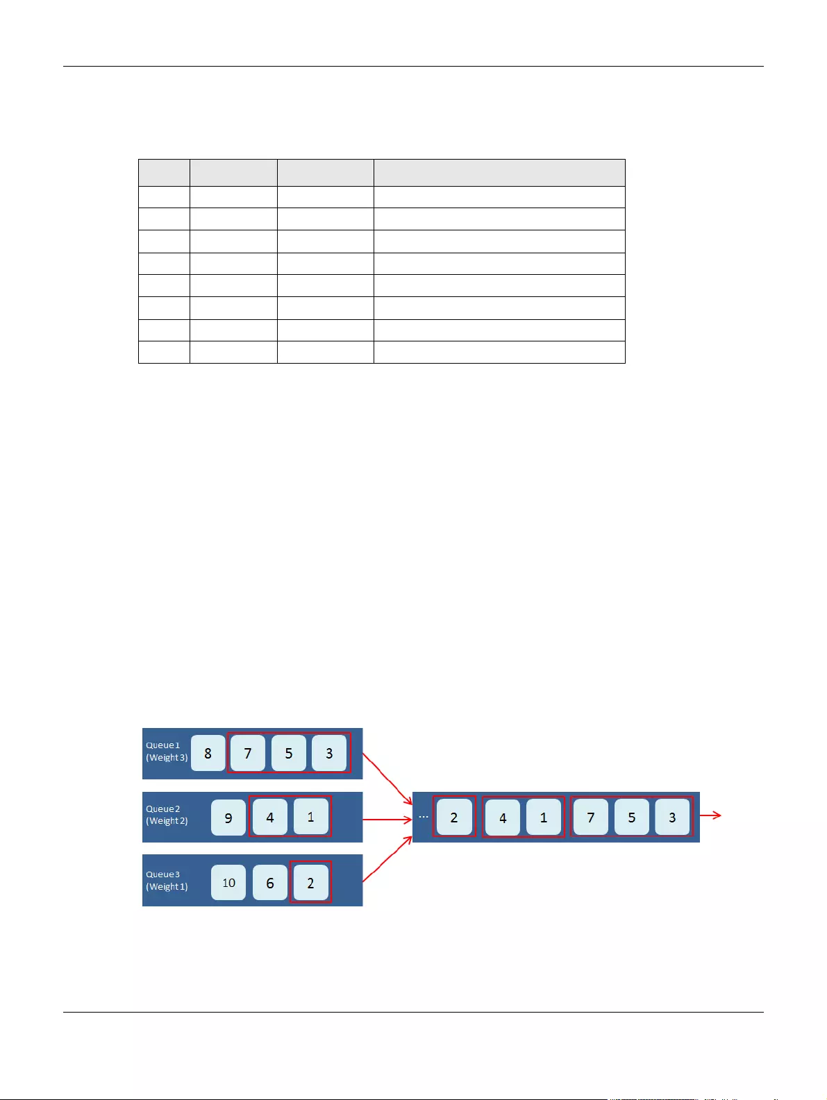
6.2.3 Weighted Round Robin Scheduling (WRR)
Round Robin Scheduling services queues on a rotating basis and is activated only when a port has more
traffic than it can handle. A queue is a given amount of bandwidth irrespective of the incoming traffic
on that port. This queue then moves to the back of the list. The next queue is given an equal amount of
bandwidth, and then moves to the end of the list; and so on, depending on the number of queues
being used. This works in a looping fashion until a queue is empty.
Weighted Round Robin Scheduling (WRR) uses the same algorithm as round robin scheduling, but
services queues based on their priority and queue weight (the number you select in the queue Weight
field) rather than a fixed amount of bandwidth. WRR is activated only when a port has more traffic than
it can handle. The bandwidth is divided across the different traffic queues according to their weights.
Queues with larger weights get more service than queues with smaller weights. This queueing
mechanism is highly efficient in that it divides any available bandwidth across the different traffic
queues and returns to queues that have not yet emptied.
Figure 11 WRR Application Example
Table 6 IEEE Priority to Traffic Type Mapping Recommendations
PCP PRIORITY ACRONYM TRAFFIC TYPES
1 0 (lowest) BK Background
0 1 (default) BE Best Effort
2 2 EE Excellent Effort
3 3 CA Critical Applications
4 4 VI Video, <100 ms latency and jitter
5 5 VO Voice, <10 ms latency and jitter
6 6 IC Internetwork Control
7 7 (highest) NC Network Control
Chapter 6 QoS
GS1200 Series User’s Guide
43
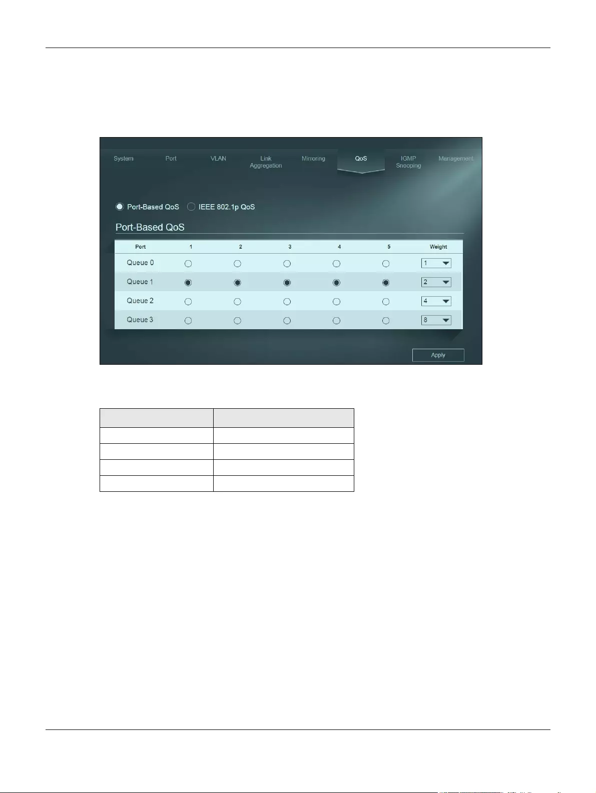
6.3 Port-Based QoS Screen
The Switch’s default settings for Port-Based QoS are shown in the next figure.
Figure 12 QoS > Port-Based QoS
The Switch allows four priority levels, shown in the table below.
To apply Port-Based QoS to the Switch, follow these steps:
1Choose which ports will carry the sensitive data, using the priority queuing levels given. Click on each
port’s radio button to assign a priority queue.
2Assign the weight (the number you select in the queue Weight field) to each priority. Remember the
weight is based on WRR Scheduling, explained in Section 11.2.3 on page 16. Bandwidth is divided across
the different traffic queues according to their weights. Queues with larger weights get more service than
queues with smaller weights.
3Click the Apply button after you are finished assigning priorities to the ports.
Table 7 Priority Queuing Levels in QoS
QUEUE NAME PRIORITY LEVEL
Queue 0 Low Priority
Queue 1 Normal Priority
Queue 2 Medium Priority
Queue 3 High Priority
Chapter 6 QoS
GS1200 Series User’s Guide
44
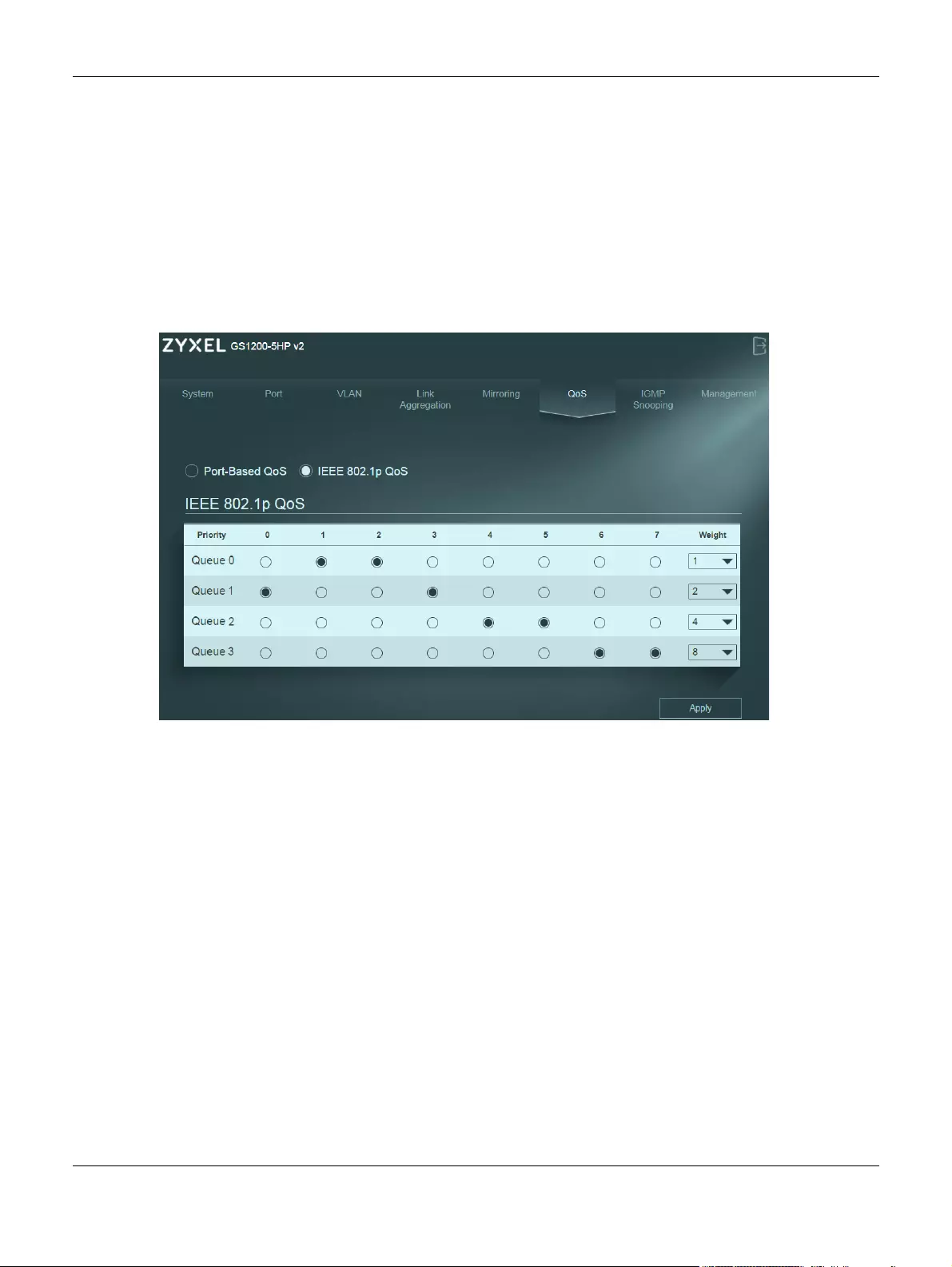
6.4 IEEE 802.1P QoS Screen
Both Port-Based QoS and IEEE 802.1P QoS use the same priority queuing levels, shown in Table 10 on
page 17. Remember the difference amongst both features relies on how the priority queuing is
assigned. Lets recap, Port-Based QoS assigns priority queuing by port, whereas IEEE 802.1P QoS assigns
queuing by PCP priority tags.
The Switch’s default settings for IEEE 802.1P QoS are shown in the next figure. The numbers from 0 to 7
refer to the priority tags for each traffic type. Refer to Table 9 on page 16.
Figure 13 QoS > IEEE 802.1P QoS
To apply IEEE 802.1P QoS to the Switch, follow these steps:
1Choose which priority tags will carry the sensitive data, using the priority queuing levels given. Click on
each priority tag’s radio button to assign a priority queue.
2Assign the weight (the number you select in the queue Weight field) to each priority. Remember the
weight is based on WRR Scheduling, explained in Section 11.2.3 on page 16. Bandwidth is divided across
the different traffic queues according to their weights. Queues with larger weights get more service than
queues with smaller weights.
3Click the Apply button after you are finished assigning priorities to the priority tags.

GS1200 Series User’s Guide
45
CHAPTER 7
IGMP Snooping
7.1 Overview
This chapter shows you how to configure various multicast features.
Traditionally, IP packets are transmitted in one of either two ways — Unicast (1 sender to 1 recipient) or
Broadcast (1 sender to everybody on the network). Multicast delivers IP packets to just a group of hosts
on the network.
IGMP (Internet Group Management Protocol) is a network-layer protocol used to establish membership
in a multicast group — it is not used to carry user data. Refer to RFC 1112, RFC 2236 and RFC 3376 for
information on IGMP versions 1, 2 and 3 respectively.
Note: You must enable IGMP snooping to use the IPTV service.
The following table introduces the IGMP snooping default settings of the Switch.
IGMP Snooping
The Switch can passively snoop on IGMP packets transferred between IP multicast routers/switches and
IP multicast hosts to learn the IP multicast group membership. It checks IGMP packets passing through it,
picks out the group registration information, and configures multicasting accordingly. IGMP snooping
allows the Switch to learn multicast groups without you having to manually configure them.
The Switch forwards multicast traffic destined for multicast groups (that it has learned from IGMP
snooping or that you have manually configured) to ports that are members of that group. IGMP
snooping generates no additional network traffic, allowing you to significantly reduce multicast traffic
passing through your Switch.
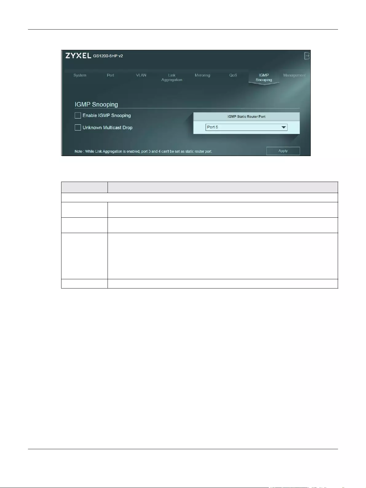
7.2 IGMP Snooping Screen
Click IGMP Snooping in the navigation panel to display the screen as shown next.
Table 8 IGMP Snooping Default Settings
GS1200-5 GS1200-5HP V2 GS1200-8 GS1200-8HP V2
Enable V
IGMP Static Router
Port will be set to
Auto.
V
IGMP Static Router
Port will be set to
Auto.
Diable V V
Chapter 7 IGMP Snooping
GS1200 Series User’s Guide
46
Figure 14 IGMP Snooping
The following table describes the labels in this screen.
Table 9 IGMP Snooping
LABEL DESCRIPTION
IGMP Snooping
Enable IGMP
Snooping
Select this option to enable IGMP Snooping to forward group multicast traffic only to ports that
are members of that group.
Unknown
Multicast Drop
Select this option to discard the frame when the Switch receives an unknown multicast frame.
Otherwise, the Switch sends the frame to all ports.
IGMP Static
Router Port
Select a port to be used as an IGMP query port.
The Switch treats an IGMP query port as being connected to an IGMP multicast router (or
server). The Switch forwards IGMP join or leave packets to an IGMP query port.
Note: If link aggregation is enabled, the ports in a link aggregation group won’t be
available in this field.
Apply Click Apply to save your changes to the Switch.

GS1200 Series User’s Guide
47
CHAPTER 8
Management
8.1 Overview
This chapter explains how to Use the Management screens to configure settings on the Switch, such as
login password change, firmware upgrade, system reset or reboot, IP address change, and so on.
8.1.1 What You Need to Know
Read this section to know more about IEEE 802.3az Energy Efficient Ethernet (EEE).
8.1.1.1 IEEE 802.3az Energy Efficient Ethernet (EEE)
If EEE is enabled, both sides of a link support EEE and there is no traffic, the port enters Low Power Idle
(LPI) mode. LPI mode turns off some functions of the physical layer (becomes quiet) to save power.
Periodically the port transmits a REFRESH signal to allow the link partner to keep the link alive. When there
is traffic to be sent, a WAKE signal is sent to the link partner to return the link to active mode.
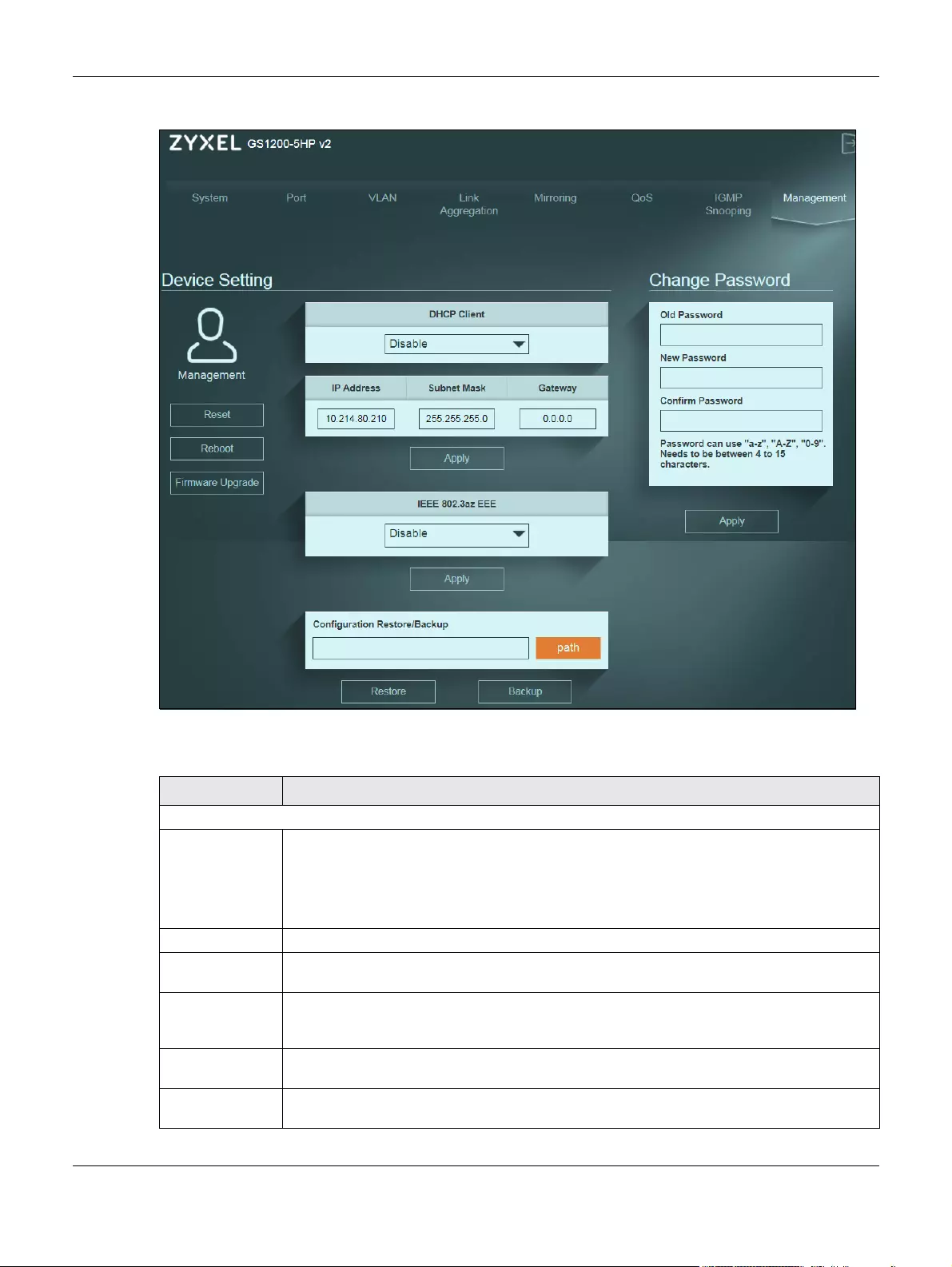
8.2 Management Screen
Use this screen to upload the latest firmware, upload a stored device configuration file, save your
configurations for later use, change the administrator system password, change the IP address, enable
DHCP client, or reboot/reset the system.
An administrator is someone who can both view and configure Switch changes. The default
administrator password is 1234.
Note: It is highly recommended that you change the default administrator password (1234).
Click Management in the navigation panel to open the following screen.
Chapter 8 Management
GS1200 Series User’s Guide
48
Figure 15 Switch Management
The following table describes the labels in this screen.
Table 10 Switch Management
LABEL DESCRIPTION
Device Setting
Reset Click this button to clear all Switch configuration information you configured and return to the
factory defaults.
If you want to access the Switch web configurator again, you may need to change the IP
address of your computer to be in the same subnet as that of the default Switch IP address
(192.168.1.3).
Reboot Click this button to restart the Switch without physically turning the power off.
Firmware
Upgrade
Click this button to upgrade the latest firmware to the Switch.
DHCP Client Select Enable if you have a DHCP server that can assign the Switch an IP address, subnet mask,
a default gateway IP address and a domain name server IP address automatically, or select
Disable.
IP Address Enter the IP address of your Switch in dotted decimal notation, for example, 192.168.1.3. This is
the IP address of the Switch in an IP routing domain.
Subnet Mask Enter the IP subnet mask of an IP routing domain in dotted decimal notation, for example,
255.255.255.0.
Chapter 8 Management
GS1200 Series User’s Guide
49
8.2.1 Firmware Upgrade Screen
Firmware upgrades contain bug fixes and fixes for security vulnerabilities. It is recommended to keep the
Switch’s firmware up to date.
Make sure you have downloaded (and unzipped) the correct model firmware and version to your
computer before uploading to the Switch.
Be sure to upload the correct model firmware as uploading the wrong
model firmware may damage your device.
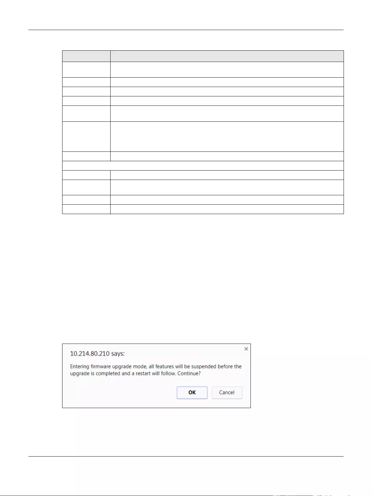
The following message will appear after you click the Firmware Upgrade button. You’re not able to
configure other settings during the firmware upgrade process to avoid crashes on the Switch. Click OK.
Figure 16 Firmware Upgrade Message
Type the path and file name of the firmware file you wish to upload to the Switch in the text box or click
path to locate it. After you select the firmware file, click the Upgrade button to load the new firmware.
After a successful upload, the system will reboot, and you’ll need to log into the Switch again.
Gateway Type the IP address of the default outgoing gateway in dotted decimal notation, for example
192.168.1.254.
Apply Click this button to save your changes to the Switch.
IEEE 802.3az EEE Select Enable to activate Energy Efficient Ethernet globally, or select Disable.
Apply Click this button to save your changes to the Switch.
Configuration
Restore/Backup
Type the path and file name of the configuration file you wish to restore in the text box or click
path to locate it.
Restore Click Restore to restore a previously saved configuration from your computer to the Switch.
Note: “config” is the name of the configuration file on the Switch, so your backup
configuration file is automatically renamed when you restore using this screen.
Backup Click Backup to save and store your current device settings.
Change Password
Old Password Type the existing system password (1234 is the default password when shipped).
New Password Enter your new system password using keyboard characters (a-z, A-Z, and 0-9). The password
must be 4 to 15 characters long
Confirm Password Retype your new system password for confirmation
Apply Click this button to save your changes to the Switch.
Table 10 Switch Management (continued)
LABEL DESCRIPTION

Chapter 8 Management
GS1200 Series User’s Guide
50
If you click the Cancel button in the Firmware Upgrade page, the Switch will reboot, and you’ll be direct
to the login screen.
Figure 17 Firmware Upgrade Path

GS1200 Series User’s Guide
51
CHAPTER 1
Troubleshooting
This chapter offers some suggestions to solve problems you might encounter. The potential problems are
divided into the following categories.
•Power, Hardware Connections, and LEDs
•Switch Access and Login
•Switch Configuration
1.1 Power, Hardware Connections, and LEDs
The Switch does not turn on. None of the LEDs turn on.
1Make sure you are using the power adaptor or cord included with the Switch.
2Make sure the power adaptor or cord is connected to the Switch and plugged in to an appropriate
power source. Make sure the power source is turned on.
3Disconnect and re-connect the power adaptor or cord to the Switch.
4If the problem continues, contact the vendor.
One of the LEDs does not behave as expected.
1Make sure you understand the normal behavior of the LED. See Section 3.3 on page 4.
2Check the hardware connections. See Section 14.1 on page 1.
3Inspect your cables for damage. Contact the vendor to replace any damaged cables.
4Disconnect and re-connect the power adaptor or cord to the Switch.
5If the problem continues, contact the vendor.
The PoE LED is off and/or power is not being supplied to my PoE-enabled device. (For GS1200-5HP
v2 and GS1200-8HP v2)

Chapter 1 Troubleshooting
GS1200 Series User’s Guide
52
1Check to see that the power adaptor is securely connected to the Switch.
2Check to see the Switch is connected to an appropriate power source, and make sure the power
source is on and functioning properly.
3Check that the Ethernet cables connection to the devices requiring PoE are connected properly.
4Make sure you are using the correct type of Ethernet cable. See Section 2.2 on page 1 for more
information about the types of Ethernet cable supported. Contact your local distributor if the problem
persists.
5Click System in the navigation panel and check if the total power requested by the PoE-enabled
devices exceed the total PoE power budget on the Switch. If it does, reconnect the PoE-enabled
devices in the order that you want the Switch to allocate power to.
See Section 5.1.3 on page 9 for the information about the maximum power the Switch and a PoE port
can supply.
A loop is detected.
See Section 7.1.1.3 on page 5 for more information about PoE.
1To restore a port in a loop state, disconnect it, check the network connections, and reconnect it.
2You can log into the Web Configurator. Go to System in the Web Configurator to check your port status.
Note that you can do this when you enable Loop Prevention (default) in the Port screen. If Loop
Detection is enabled, you can’t log into the Switch.
1.2 Switch Access and Login
I forgot the IP address for the Switch.
1The default IP address is 192.168.1.3.
2If this does not work, you have to reset the device to its factory defaults. See Section 4.5 on page 5.
I forgot the password.
1The default password is 1234.
2If this does not work, you have to reset the device to its factory defaults. See Section 4.5 on page 5.

Chapter 1 Troubleshooting
GS1200 Series User’s Guide
53
I cannot see or access the Login screen in the web configurator.
1Make sure you are using the correct IP address.
• The default IP address is 192.168.1.3.
• If you changed the IP address, use the new IP address.
• If you changed the IP address and have forgotten it, see the troubleshooting suggestions for I
forgot the IP address for the Switch.
2Check the hardware connections, and make sure the LEDs are behaving as expected. See Section 3.3
on page 4.
3Make sure your Internet browser does not block pop-up windows and has JavaScripts and Java
enabled.
4Make sure your computer is in the same subnet as the Switch. (If you know that there are routers
between your computer and the Switch, skip this step.)
5Reset the device to its factory defaults, and try to access the Switch with the default IP address. See
Section 4.5 on page 5.
6If the problem continues, contact the vendor, or try one of the advanced suggestions.
I can see the Login screen, but I cannot log in to the Switch.
1Make sure you have entered the password correctly. The default password is 1234.
2Disconnect and re-connect the cord to the Switch.
3If this does not work, you have to reset the device to its factory defaults. See Section 4.5 on page 5.
Pop-up Windows, JavaScripts and Java Permissions
In order to use the web configurator you need to allow:
• Web browser pop-up windows from your device.
• JavaScripts (enabled by default).
• Java permissions (enabled by default).

Chapter 1 Troubleshooting
GS1200 Series User’s Guide
54
1.3 Switch Configuration
After upgrading firmware on the Switch, the login screen doesn’t display.
You will see the Firmware Upgrade screen, when one of the following situations happens. These will lead
to a failure at upgrading firmware.
During the firmware upgrade process:
• The Switch loses power.
• The computer from which you uploaded the firmware file to the Switch is turned off.
• The Ethernet cable connecting the Switch and the computer comes loose. It’s the computer from
which you uploaded the firmware file to the Switch.
When one of the situations above happens, and you’re directed to the Firmware Upgrade screen,
follow the steps below:
1Make sure the power supply is sufficient in your environment.
2Make sure your computer’s Ethernet cable is securely connected to the Switch.
3Select the firmware file that you tried to upload to the Switch before you upgrade firmware again in the
Firmware Upgrade screen.
4Wait for the firmware upgrade process to complete. After a successful upload, the system will reboot,
and you’ll need to log into the Switch again.

GS1200 Series User’s Guide
55
APPENDIX A
Customer Support
In the event of problems that cannot be solved by using this manual, you should contact your vendor. If
you cannot contact your vendor, then contact a Zyxel office for the region in which you bought the
device.
See http://www.zyxel.com/homepage.shtml and also
http://www.zyxel.com/about_zyxel/zyxel_worldwide.shtml for the latest information.
Please have the following information ready when you contact an office.
Required Information
• Product model and serial number.
• Warranty Information.
• Date that you received your device.
• Brief description of the problem and the steps you took to solve it.
Corporate Headquarters (Worldwide)
Taiwan
• Zyxel Communications Corporation
• http://www.zyxel.com
Asia
China
• Zyxel Communications (Shanghai) Corp.
Zyxel Communications (Beijing) Corp.
Zyxel Communications (Tianjin) Corp.
• http://www.zyxel.cn
India
•Zyxel Technology India Pvt Ltd
• http://www.zyxel.in
Kazakhstan
•Zyxel Kazakhstan
• http://www.zyxel.kz

Appendix A Customer Support
GS1200 Series User’s Guide
56
Korea
• Zyxel Korea Corp.
• http://www.zyxel.kr
Malaysia
• Zyxel Malaysia Sdn Bhd.
• http://www.zyxel.com.my
Pakistan
• Zyxel Pakistan (Pvt.) Ltd.
• http://www.zyxel.com.pk
Philippines
• Zyxel Philippines
• http://www.zyxel.com.ph
Singapore
• Zyxel Singapore Pte Ltd.
• http://www.zyxel.com.sg
Taiwan
• Zyxel Communications Corporation
• http://www.zyxel.com/tw/zh/
Thailand
• Zyxel Thailand Co., Ltd
• http://www.zyxel.co.th
Vietnam
• Zyxel Communications Corporation-Vietnam Office
• http://www.zyxel.com/vn/vi
Europe
Austria
•Zyxel Deutschland GmbH
• http://www.zyxel.de
Belarus
•Zyxel BY
• http://www.zyxel.by

Appendix A Customer Support
GS1200 Series User’s Guide
57
Belgium
• Zyxel Communications B.V.
• http://www.zyxel.com/be/nl/
• http://www.zyxel.com/be/fr/
Bulgaria
•Zyxel България
• http://www.zyxel.com/bg/bg/
Czech Republic
• Zyxel Communications Czech s.r.o
• http://www.zyxel.cz
Denmark
• Zyxel Communications A/S
• http://www.zyxel.dk
Estonia
• Zyxel Estonia
• http://www.zyxel.com/ee/et/
Finland
• Zyxel Communications
• http://www.zyxel.fi
France
•Zyxel France
• http://www.zyxel.fr
Germany
•Zyxel Deutschland GmbH
• http://www.zyxel.de
Hungary
• Zyxel Hungary & SEE
• http://www.zyxel.hu
Italy
• Zyxel Communications Italy
• http://www.zyxel.it/

Appendix A Customer Support
GS1200 Series User’s Guide
58
Latvia
•Zyxel Latvia
• http://www.zyxel.com/lv/lv/homepage.shtml
Lithuania
•Zyxel Lithuania
• http://www.zyxel.com/lt/lt/homepage.shtml
Netherlands
• Zyxel Benelux
• http://www.zyxel.nl
Norway
• Zyxel Communications
• http://www.zyxel.no
Poland
• Zyxel Communications Poland
• http://www.zyxel.pl
Romania
• Zyxel Romania
• http://www.zyxel.com/ro/ro
Russia
• Zyxel Russia
• http://www.zyxel.ru
Slovakia
• Zyxel Communications Czech s.r.o. organizacna zlozka
• http://www.zyxel.sk
Spain
• Zyxel Communications ES Ltd
• http://www.zyxel.es
Sweden
• Zyxel Communications
• http://www.zyxel.se
Switzerland
•Studerus AG

Appendix A Customer Support
GS1200 Series User’s Guide
59
• http://www.zyxel.ch/
Turkey
• Zyxel Turkey A.S.
• http://www.zyxel.com.tr
UK
• Zyxel Communications UK Ltd.
• http://www.zyxel.co.uk
Ukraine
•Zyxel Ukraine
• http://www.ua.zyxel.com
Latin America
Argentina
• Zyxel Communication Corporation
• http://www.zyxel.com/ec/es/
Brazil
• Zyxel Communications Brasil Ltda.
• https://www.zyxel.com/br/pt/
Ecuador
• Zyxel Communication Corporation
• http://www.zyxel.com/ec/es/
Middle East
Israel
• Zyxel Communication Corporation
• http://il.zyxel.com/homepage.shtml
Middle East
• Zyxel Communication Corporation
• http://www.zyxel.com/me/en/

Appendix A Customer Support
GS1200 Series User’s Guide
60
North America
USA
• Zyxel Communications, Inc. — North America Headquarters
• http://www.zyxel.com/us/en/
Oceania
Australia
• Zyxel Communications Corporation
• http://www.zyxel.com/au/en/
Africa
South Africa
• Nology (Pty) Ltd.
• http://www.zyxel.co.za

GS1200 Series User’s Guide
61
APPENDIX A
Legal Information
Copyright
Copyright © 2017 by Zyxel Communications Corporation.
The contents of this publication may not be reproduced in any part or as a whole, transcribed, stored in a retrieval system, translated into any
language, or transmitted in any form or by any means, electronic, mechanical, magnetic, optical, chemical, photocopying, manual, or
otherwise, without the prior written permission of Zyxel Communications Corporation.
Published by Zyxel Communications Corporation. All rights reserved.
Disclaimer
Zyxel does not assume any liability arising out of the application or use of any products, or software described herein. Neither does it convey any
license under its patent rights nor the patent rights of others. Zyxel further reserves the right to make changes in any products described herein
without notice. This publication is subject to change without notice.
Regulatory Notice and Statement
UNITED STATES of AMERICA
The following information applies if you use the product within USA area.
FCC EMC Statement
• The device complies with Part 15 of FCC rules. Operation is subject to the following two conditions:
(1) This device may not cause harmful interference, and
(2) This device must accept any interference received, including interference that may cause undesired operation.
• Changes or modifications not expressly approved by the party responsible for compliance could void the user’s authority to operate the
device.
• This product has been tested and complies with the specifications for a Class B digital device, pursuant to Part 15 of the FCC Rules. These
limits are designed to provide reasonable protection against harmful interference in a residential installation. This device generates, uses, and
can radiate radio frequency energy and, if not installed and used according to the instructions, may cause harmful interference to radio
communications. However, there is no guarantee that interference will not occur in a particular installation.
• If this device does cause harmful interference to radio or television reception, which is found by turning the device off and on, the user is
encouraged to try to correct the interference by one or more of the following measures:
• Reorient or relocate the receiving antenna
• Increase the separation between the devices
• Connect the equipment to an outlet other than the receiver’s
• Consult a dealer or an experienced radio/TV technician for assistance
CANADA
The following information applies if you use the product within Canada area
Industry Canada ICES statement
CAN ICES-3 (B)/NMB-3(B)
EUROPEA N UNION
The following information applies if you use the product within the European Union.

Appendix A Legal Information
GS1200 Series User’s Guide
62
List of national codes
Safety Warnings
• Do not use this product near water, for example, in a wet basement or near a swimming pool.
• Do not expose your device to dampness, dust or corrosive liquids.
• Do not store things on the device.
• Do not obstruct the device ventilation slots as insufficient airflow may harm your device. For example, do not place the device in an
enclosed space such as a box or on a very soft surface such as a bed or sofa.
• Do not install, use, or service this device during a thunderstorm. There is a remote risk of electric shock from lightning.
• Connect ONLY suitable accessories to the device.
• Do not open the device or unit. Opening or removing covers can expose you to dangerous high voltage points or other risks.
• Only qualified service personnel should service or disassemble this device. Please contact your vendor for further information.
• Make sure to connect the cables to the correct ports.
• Place connecting cables carefully so that no one will step on them or stumble over them.
• Always disconnect all cables from this device before servicing or disassembling.
• Do not remove the plug and connect it to a power outlet by itself; always attach the plug to the power adaptor first before connecting it to
a power outlet.
• Do not allow anything to rest on the power adaptor or cord and do NOT place the product where anyone can walk on the power adaptor
or cord.
• Please use the provided or designated connection cables/power cables/ adaptors. Connect it to the right supply voltage (for example,
110V AC in North America or 230V AC in Europe). If the power adaptor or cord is damaged, it might cause electrocution. Remove it from the
device and the power source, repairing the power adapter or cord is prohibited. Contact your local vendor to order a new one.
• Do not use the device outside, and make sure all the connections are indoors. There is a remote risk of electric shock from lightning.
• CAUTION: Risk of explosion if battery is replaced by an incorrect type, dispose of used batteries according to the instruction. Dispose them at
the applicable collection point for the recycling of electrical and electronic devices. For detailed information about recycling of this
product, please contact your local city office, your household waste disposal service or the store where you purchased the product.
• The POE (Power over Ethernet) devices that supply or receive power and their connected Ethernet cables must all be completely indoors.
• The following warning statements apply, where the disconnect device is not incorporated in the device or where the plug on the power
supply cord is intended to serve as the disconnect device,
— For permanently connected devices, a readily accessible disconnect device shall be incorporated external to the device;
— For pluggable devices, the socket-outlet shall be installed near the device and shall be easily accessible.
Environment Statement
ErP (Energy-related Products)
Zyxel products put on the EU market in compliance with the requirement of the European Parliament and the Council published Directive 2009/
125/EC establishing a framework for the setting of ecodesign requirements for energy-related products (recast), so called as «ErP Directive
(Energy-related Products directive) as well as ecodesign requirement laid down in applicable implementing measures, power consumption has
satisfied regulation requirements which are:
• Network standby power consumption < 8W, and/or
• Off mode power consumption < 0.5W, and/or
• Standby mode power consumption < 0.5W.
(Wireless setting, please refer to «Wireless» chapter for more detail.)
COUNTRY ISO 3166 2 LETTER CODE COUNTRY ISO 3166 2 LETTER CODE
Austria AT Liechtenstein LI
Belgium BE Lithuania LT
Bulgaria BG Luxembourg LU
Croatia HR Malta MT
Cyprus CY Netherlands NL
Czech Republic CZ Norway NO
Denmark DK Poland PL
Estonia EE Portugal PT
Finland FI Romania RO
France FR Serbia RS
Germany DE Slovakia SK
Greece GR Slovenia SI
Hungary HU Spain ES
Iceland IS Switzerland CH
Ireland IE Sweden SE
Italy IT Turkey TR
Latvia LV United Kingdom GB

Appendix A Legal Information
GS1200 Series User’s Guide
63
European Union — Disposal and Recycling Information
The symbol below means that according to local regulations your product and/or its battery shall be disposed of separately from domestic
waste. If this product is end of life, take it to a recycling station designated by local authorities. At the time of disposal, the separate collection of
your product and/or its battery will help save natural resources and ensure that the environment is sustainable development.
Die folgende Symbol bedeutet, dass Ihr Produkt und/oder seine Batterie gemäß den örtlichen Bestimmungen getrennt vom Hausmüll entsorgt
werden muss. Wenden Sie sich an eine Recyclingstation, wenn dieses Produkt das Ende seiner Lebensdauer erreicht hat. Zum Zeitpunkt der
Entsorgung wird die getrennte Sammlung von Produkt und/oder seiner Batterie dazu beitragen, natürliche Ressourcen zu sparen und die Umwelt
und die menschliche Gesundheit zu schützen.
El símbolo de abajo indica que según las regulaciones locales, su producto y/o su batería deberán depositarse como basura separada de la
doméstica. Cuando este producto alcance el final de su vida útil, llévelo a un punto limpio. Cuando llegue el momento de desechar el
producto, la recogida por separado éste y/o su batería ayudará a salvar los recursos naturales y a proteger la salud humana y
medioambiental.
Le symbole ci-dessous signifie que selon les réglementations locales votre produit et/ou sa batterie doivent être éliminés séparément des ordures
ménagères. Lorsque ce produit atteint sa fin de vie, amenez-le à un centre de recyclage. Au moment de la mise au rebut, la collecte séparée
de votre produit et/ou de sa batterie aidera à économiser les ressources naturelles et protéger l’environnement et la santé humaine.
Il simbolo sotto significa che secondo i regolamenti locali il vostro prodotto e/o batteria deve essere smaltito separatamente dai rifiuti domestici.
Quando questo prodotto raggiunge la fine della vita di servizio portarlo a una stazione di riciclaggio. Al momento dello smaltimento, la raccolta
separata del vostro prodotto e/o della sua batteria aiuta a risparmiare risorse naturali e a proteggere l’ambiente e la salute umana.
Symbolen innebär att enligt lokal lagstiftning ska produkten och/eller dess batteri kastas separat från hushållsavfallet. När den här produkten når
slutet av sin livslängd ska du ta den till en återvinningsstation. Vid tiden för kasseringen bidrar du till en bättre miljö och mänsklig hälsa genom att
göra dig av med den på ett återvinningsställe.
台灣
安全警告 — 為了您的安全,請先閱讀以下警告及指示 :
• 請勿將此產品接近水、火焰或放置在高溫的環境。
• 避免設備接觸
— 任何液體 — 切勿讓設備接觸水、雨水、高濕度、污水腐蝕性的液體或其他水份。
— 灰塵及污物 — 切勿接觸灰塵、污物、沙土、食物或其他不合適的材料。
• 雷雨天氣時,不要安裝,使用或維修此設備。有遭受電擊的風險。
• 切勿重摔或撞擊設備,並勿使用不正確的電源變壓器。
• 若接上不正確的電源變壓器會有爆炸的風險。
• 請勿隨意更換產品內的電池。
• 如果更換不正確之電池型式,會有爆炸的風險,請依製造商說明書處理使用過之電池。
• 請將廢電池丟棄在適當的電器或電子設備回收處。
• 請勿將設備解體。
• 請勿阻礙設備的散熱孔,空氣對流不足將會造成設備損害。
• 請插在正確的電壓供給插座 ( 如 : 北美 / 台灣電壓 110V AC,歐洲是 230V AC)。
• 假若電源變壓器或電源變壓器的纜線損壞,請從插座拔除,若您還繼續插電使用,會有觸電死亡的風險。
• 請勿試圖修理電源變壓器或電源變壓器的纜線,若有毀損,請直接聯絡您購買的店家,購買一個新的電源變壓器。
• 請勿將此設備安裝於室外,此設備僅適合放置於室內。
• 請勿隨一般垃圾丟棄。
• 請參閱產品背貼上的設備額定功率。
• 請參考產品型錄或是彩盒上的作業溫度。
• 產品沒有斷電裝置或者採用電源線的插頭視為斷電裝置的一部分,以下警語將適用 :
— 對永久連接之設備, 在設備外部須安裝可觸及之斷電裝置;
— 對插接式之設備, 插座必須接近安裝之地點而且是易於觸及的。
About the Symbols
Various symbols are used in this product to ensure correct usage, to prevent danger to the user and others, and to prevent property damage.
The meaning of these symbols are described below. It is important that you read these descriptions thoroughly and fully understand the
contents.
Appendix A Legal Information
GS1200 Series User’s Guide
64
Explanation of the Symbols
Viewing Certifications
Go to http://www.zyxel.com to view this product’s documentation and certifications.
Zyxel Limited Warranty
Zyxel warrants to the original end user (purchaser) that this product is free from any defects in material or workmanship for a specific period (the
Warranty Period) from the date of purchase. The Warranty Period varies by region. Check with your vendor and/or the authorized Zyxel local
distributor for details about the Warranty Period of this product. During the warranty period, and upon proof of purchase, should the product
have indications of failure due to faulty workmanship and/or materials, Zyxel will, at its discretion, repair or replace the defective products or
components without charge for either parts or labor, and to whatever extent it shall deem necessary to restore the product or components to
proper operating condition. Any replacement will consist of a new or re-manufactured functionally equivalent product of equal or higher value,
and will be solely at the discretion of Zyxel. This warranty shall not apply if the product has been modified, misused, tampered with, damaged by
an act of God, or subjected to abnormal working conditions.
Note
Repair or replacement, as provided under this warranty, is the exclusive remedy of the purchaser. This warranty is in lieu of all other warranties,
express or implied, including any implied warranty of merchantability or fitness for a particular use or purpose. Zyxel shall in no event be held
liable for indirect or consequential damages of any kind to the purchaser.
To obtain the services of this warranty, contact your vendor. You may also refer to the warranty policy for the region in which you bought the
device at http://www.zyxel.com/web/support_warranty_info.php.
Registration
Register your product online to receive e-mail notices of firmware upgrades and information at www.zyxel.com for global products, or at
www.us.zyxel.com for North American products.
Trademarks
ZyNOS (Zyxel Network Operating System) and ZON (Zyxel One Network) are registered trademarks of Zyxel Communications, Inc. Other
trademarks mentioned in this publication are used for identification purposes only and may be properties of their respective owners.
Open Source Licenses
This product contains in part some free software distributed under GPL license terms and/or GPL like licenses. Open source licenses are provided
with the firmware package. You can download the latest firmware at www.zyxel.com. To obtain the source code covered under those Licenses,
please contact support@zyxel.com.tw to get it.
SYMBOL EXPLANATION
Alternating current (AC):
AC is an electric current in which the flow of electric charge periodically reverses direction.
Direct current (DC):
DC if the unidirectional flow or movement of electric charge carriers.
Earth; ground:
A wiring terminal intended for connection of a Protective Earthing Conductor.
Class II equipment:
The method of protection against electric shock in the case of class II equipment is either double insulation or
reinforced insulation.

Index
GS1200 Series User’s Guide
65
Index
A
airflow 3
applications
backbone 2
C
certifications 2
viewing 4
CFI 8
CFI (Canonical Format Indicator) 8
changing the password 4
contact information 1
copyright 1
customer support 1
D
default IP 1
disclaimer 1
F
front panel 2
H
hardware installation 1
hardware overview 2
I
IGMP snooping 19
initial setup 6
installation
desktop 1
installation scenarios 1
L
LEDs 4
login 1
password 4
login account
Administrator 21
M
managing the device
good habits 3
N
network applications 2
P
password 4
port VLAN ID, see PVID 9
power connector 3
product registration 4
PVID 8

Index
GS1200 Series User’s Guide
66
R
rear panel connections 3
registration
product 4
resetting 5
restoring configuration 5
S
status 2
switch reset 5
T
tagged VLAN 8
trademarks 4
V
VID 10
number of possible VIDs 8
priority frame 8
VID (VLAN Identifier) 8
VLAN
ID 8
introduction 8
PVID 9
tagged 8
VLAN ID 8, 10
W
warranty 4
note 4
web configurator
home 2
login 1
logout 5
View the manual for the ZyXEL GS1200-8 here, for free. This user manual comes under the category switches and has been rated by 1 people with an average of a 8.7. This manual is available in the following languages: English. Do you have a question about the ZyXEL GS1200-8?
Ask your question here
Frequently asked questions
Can’t find the answer to your question in the manual? You may find the answer to your question in the FAQs about the ZyXEL GS1200-8 below.
What is the weight of the ZyXEL GS1200-8?
The ZyXEL GS1200-8 has a weight of 325 g.
What is the height of the ZyXEL GS1200-8?
The ZyXEL GS1200-8 has a height of 26 mm.
What is the width of the ZyXEL GS1200-8?
The ZyXEL GS1200-8 has a width of 155 mm.
What is the depth of the ZyXEL GS1200-8?
The ZyXEL GS1200-8 has a depth of 85 mm.
Is the manual of the ZyXEL GS1200-8 available in English?
Yes, the manual of the ZyXEL GS1200-8 is available in English .
Is your question not listed? Ask your question here
Default Login Details
User’s Guide
GS1200 Series
GS1200-5/GS1200-5HP v2/GS1200-8/GS1200-8HP v2
5-Port / 8-Port Web Managed (PoE) Gigabit Switch
LAN IP Address http://192.168.1.3
Password 1234
Version 1.00 Edition 2, 12/2018
Copyright © 2018 Zyxel Communications Corporation

IMPORTANT!
READ CAREFULLY BEFORE USE.
KEEP THIS GUIDE FOR FUTURE REFERENCE.
This is a User’s Guide for a series of products. Not all products support all firmware features. Screenshots
and graphics in this book may differ slightly from your product due to differences in your product
firmware or your computer operating system. Every effort has been made to ensure that the information
in this manual is accurate.
Related Documentation
•Quick Start Guide
The Quick Start Guide shows how to connect the Switch and access the Web Configurator.
•More Information
Go to support.zyxel.com to find other information on the Switch
.
GS1200 Series User’s Guide
2
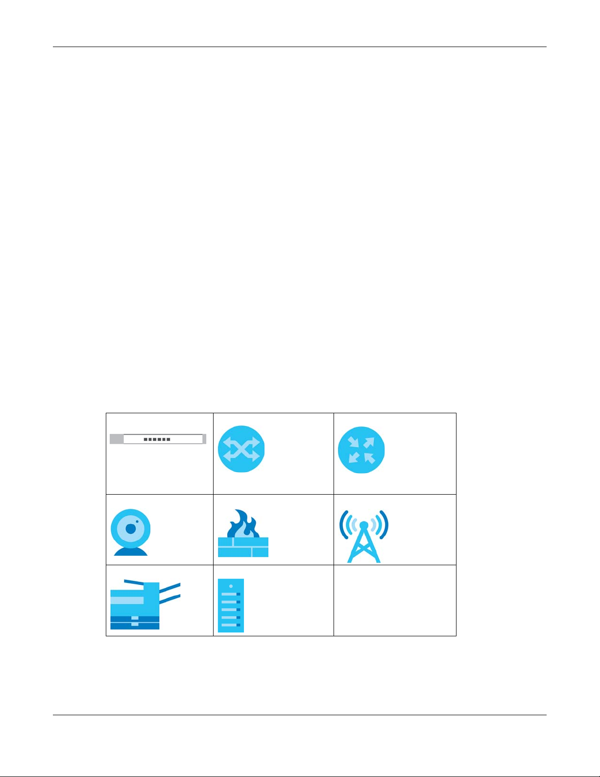
Document Conventions
Document Conventions
Warnings and Notes
These are how warnings and notes are shown in this guide.
Warnings tell you about things that could harm you or your device.
Note: Notes tell you other important information (for example, other things you may need to
configure or helpful tips) or recommendations.
Syntax Conventions
• The GS1200-5, GS1200-5HP v2, GS1200-8, and GS1200-8HP v2 may be referred to as the “Switch” in this
guide.
• Product labels, screen names, field labels and field choices are all in bold font.
• A right angle bracket ( > ) within a screen name denotes a mouse click. For example, QoS > Port-
Based QoS means you first click QoS in the navigation panel, then the Port-Based QoS sub menu to
get to that screen.
Icons Used in Figures
Figures in this user guide may use the following generic icons. The Switch icon is not an exact
representation of your device.
Switch Generic Switch Generic Router
IP Camera Firewall Cell Tower
Printer Server
GS1200 Series User’s Guide
3

Contents Overview
Contents Overview
User’s Guide ……………………………………………………………………………………………………………………….8
Getting to Know Your Switch …………………………………………………………………………………………………. 9
Hardware Installation …………………………………………………………………………………………………………… 12
Hardware Panels …………………………………………………………………………………………………………………. 13
The Web Configurator …………………………………………………………………………………………………………. 16
Initial Setup Example ……………………………………………………………………………………………………………. 21
Technical Reference …………………………………………………………………………………………………………26
System …………………………………………………………………………………………………………………………………. 27
Port ……………………………………………………………………………………………………………………………………… 30
VLAN …………………………………………………………………………………………………………………………………… 34
Link Aggregation …………………………………………………………………………………………………………………. 37
Mirroring ………………………………………………………………………………………………………………………………. 39
QoS ……………………………………………………………………………………………………………………………………… 41
IGMP Snooping ……………………………………………………………………………………………………………………. 45
Management ………………………………………………………………………………………………………………………. 47
Troubleshooting …………………………………………………………………………………………………………………… 51
GS1200 Series User’s Guide
4

Table of Contents
Table of Contents
Document Conventions ………………………………………………………… …………………………………………….3
Contents Overview………………………………………………………………………………………………………………4
Table of Contents…………………………………………………………………………………………………………………5
Part I: User’s Guide……………………………………………………………………………….. 8
Chapter 1
Getting to Know Your Switch ………………………………………………………………………………………………..9
1.1 Introduction ……………………………………………………………………………………………………………………… 9
1.2 Applications …………………………………………………………………………………………………………………… 10
1.2.1 Bridging Application ………………………………………………………………………………………………. 10
1.2.2 VLAN Application Example …………………………………………………………………………………….. 10
1.3 Ways to Manage the Switch …………………………………………………………………………………………… 11
1.4 Good Habits for Managing the Switch …………………………………………………………………………….11
Chapter 2
Hardware Installation …………………………………………………………………………………………………………12
2.1 Installation Scenarios ………………………………………………………………………………………………………. 12
2.2 Desktop Installation Procedure ………………………………………………………………………………………. 12
Chapter 3
Hardware Panels………………………………………………………………………………………………………………..13
3.1 Front Panel …………………………………………………………………………………………………………………….. 13
3.2 Rear Panel ……………………………………………………………………………………………………………………… 13
3.2.1 Power Connector ………………………………………………………………………………………………….. 14
3.3 LEDs ……………………………………………………………………………………………………………………………… 15
Chapter 4
The Web Configurator…………………………………………………………………………………………………………16
4.1 Overview ……………………………………………………………………………………………………………………….. 16
4.2 System Login ………………………………………………………………………………………………………………….. 16
4.3 The Web Configurator Layout ………………………………………………………………………………………… 17
4.3.1 Change Your Password …………………………………………………………………………………………. 19
4.4 Switch Lockout ……………………………………………………………………………………………………………….. 19
4.5 Resetting the Switch ………………………………………………………………………………………………………. 20
4.6 Logging Out of the Web Configurator ……………………………………………………………………………20
GS1200 Series User’s Guide
5

Table of Contents
Chapter 5
Initial Setup Example………………………………………………………………………………………………………….21
5.1 Overview ……………………………………………………………………………………………………………………….. 21
5.1.1 Creating a VLAN ……………………………………………………………………………………………………. 21
5.1.2 Setting Port VID ………………………………………………………………………………………………………. 23
5.1.3 Power over Ethernet (PoE) Configuration ……………………………………………………………….. 24
Part II: Technical Reference………………………………………………………………… 26
Chapter 6
System……………………………………………………………………………………………………………………………….27
6.1 Overview ……………………………………………………………………………………………………………………….. 27
6.2 System Screen ………………………………………………………………………………………………………………… 27
Chapter 7
Port ……………………………………………………………………………………………………………………………………30
7.1 Overview ……………………………………………………………………………………………………………………….. 30
7.1.1 What You Need to Know ……………………………………………………………………………………….. 30
7.2 Port Screen …………………………………………………………………………………………………………………….. 31
Chapter 8
VLAN………………………………………………………………………………………………………………………………….34
8.1 Overview ……………………………………………………………………………………………………………………….. 34
8.1.1 What You Need to Know ……………………………………………………………………………………….. 34
8.2 VLAN Screen ………………………………………………………………………………………………………………….. 35
Chapter 9
Link Aggregation ……………………………… …. …. … …………………………………….. …. …. ……………………….37
9.1 Overview ……………………………………………………………………………………………………………………….. 37
9.2 Link Aggregation Screen ………………………………………………………………………………………………… 37
Chapter 10
Mirroring…………………………………………………………………………………………………………………………….39
10.1 Overview ……………………………………………………………………………………………………………………… 39
10.2 Mirroring Screen ……………………………………………………………………………………………………………. 39
Chapter 11
QoS……………………………………………………………………………………………………………………………………41
11.1 Overview ……………………………………………………………………………………………………………………… 41
11.2 What You Need to Know ………………………………………………………………………………………………. 41
11.2.1 Port-Based QoS ……………………………………………………………………………………………………. 41
GS1200 Series User’s Guide
6

Table of Contents
11.2.2 IEEE 802.1p QoS ……………………………………………………………………………………………………. 41
11.2.3 Weighted Round Robin Scheduling (WRR) ……………………………………………………………. 42
11.3 Port-Based QoS Screen …………………………………………………………………………………………………. 43
11.4 IEEE 802.1P QoS Screen …………………………………………………………………………………………………. 44
Chapter 12
IGMP Snooping ………………………………………………………………………………………………………………….45
12.1 Overview ……………………………………………………………………………………………………………………… 45
12.2 IGMP Snooping Screen …………………………………………………………………………………………………. 45
Chapter 13
Management …………………………………………………………………………………………………………………….47
13.1 Overview ……………………………………………………………………………………………………………………… 47
13.1.1 What You Need to Know ………………………………………………………………………………………47
13.2 Management Screen …………………………………………………………………………………………………… 47
13.2.1 Firmware Upgrade Screen …………………………………………………………………………………….49
Chapter 14
Troubleshooting………………………………………………………………………………………………………………….51
14.1 Power, Hardware Connections, and LEDs ……………………………………………………………………… 51
14.2 Switch Access and Login ………………………………………………………………………………………………. 52
14.3 Switch Configuration …………………………………………………………………………………………………….. 54
Appendix A Customer Support …………………………………………………………………………………………. 55
Appendix B Legal Information…………………………………………………………………………………………… 61
Index…………………………………………………………………………………………………………………………………66
GS1200 Series User’s Guide
7

PART I
User’s Guide
8

CHAPTER 1
Getting to Know Your Switch
1.1 Introduction
This chapter introduces the main features and applications of the Switch. The GS1200 Series consists of
the following models:
• GS1200-5
• GS1200-5HP v2
• GS1200-8
• GS1200-8HP v2
The Switch has 5/8 ports. You can easily connect different devices, such as computers, network storage
devices, IP cameras, print servers to your home network.
The PoE ports of the GS1200-5HP v2 and GS1200-8HP v2 support IEEE802.3at High Power over Ethernet
(PoE) and IEEE802.3af PoE standard, to provide power to IP CAM, wall mounted AP, and other devices
that may be far from a power outlet.
For an advanced user, the Switch also provides a utility like web configurator to give you an easy
configuration for VLAN, QoS, basis system management, and firmware upgrade. The Switch is compliant
with IEEE802.3az (Energy Efficient Ethernet Standard), and provides power-saving benefits without
compromising performance.
Key feature differences between Switch models are as follows. Other features are common to all
models.
Table 1 GS1200 Series Comparison Table
MODEL GS1200-5 GS1200-5HP V2 GS1200-8 GS1200-8HP V2
Total Port Number5588
10/100/1000 Mbps PoE
Ports
10/100/1000 Mbps
Ethernet Ports
PoE Feature
PoE Maximum Power — 60W PoE power
Power ON/OFF Switch-v-v
802.1p QoS and PortBased QoS
— Ports 1-4 — Ports 1-4
Ports 1-5 Port 5 Ports 1-8 Ports 5-8
—
vvvv
IEEE 802.3 af PoE
IEEE 802.3at High
Power over Ethernet
(PoE)
budget
—
— 60W PoE power
IEEE 802.3 af PoE
IEEE 802.3at High
Power over Ethernet
(PoE)
budget
GS1200 Series User’s Guide
9
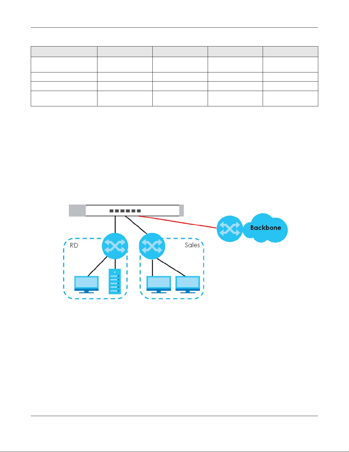
Chapter 1 Getting to Know Your Switch
Table 1 GS1200 Series Comparison Table
MODEL GS1200-5 GS1200-5HP V2 GS1200-8 GS1200-8HP V2
IGMP Snooping v1/v2
and v3 Compatible
Broadcast Storm Controlvvvv
Firmware Upgradevvvv
Configuration Restore
and Backup
vvvv
vvvv
1.2 Applications
This section shows a few examples of using the Switch in various network environments.
1.2.1 Bridging Application
In this example the Switch connects different company departments (RD and Sales) to the corporate
backbone. It can alleviate bandwidth contention and eliminate server and network bottlenecks. All
users that need high bandwidth can connect to high-speed department servers via the Switch.
Figure 1 Bridging Application
1.2.2 VLAN Application Example
A VLAN (Virtual Local Area Network) allows a physical network to be partitioned into multiple logical
networks. Stations on a logical network belong to one or more groups. With VLAN, a station cannot
directly talk to or hear from stations that are not in the same group(s) unless such traffic first goes through
a router.
1.2.2.1 Tag-based VLAN Example
Ports in the same VLAN group share the same frame broadcast domain, thus increasing network
performance by reducing broadcast traffic. VLAN groups can be modified at any time by adding,
moving or changing ports without any re-cabling.
GS1200 Series User’s Guide
10
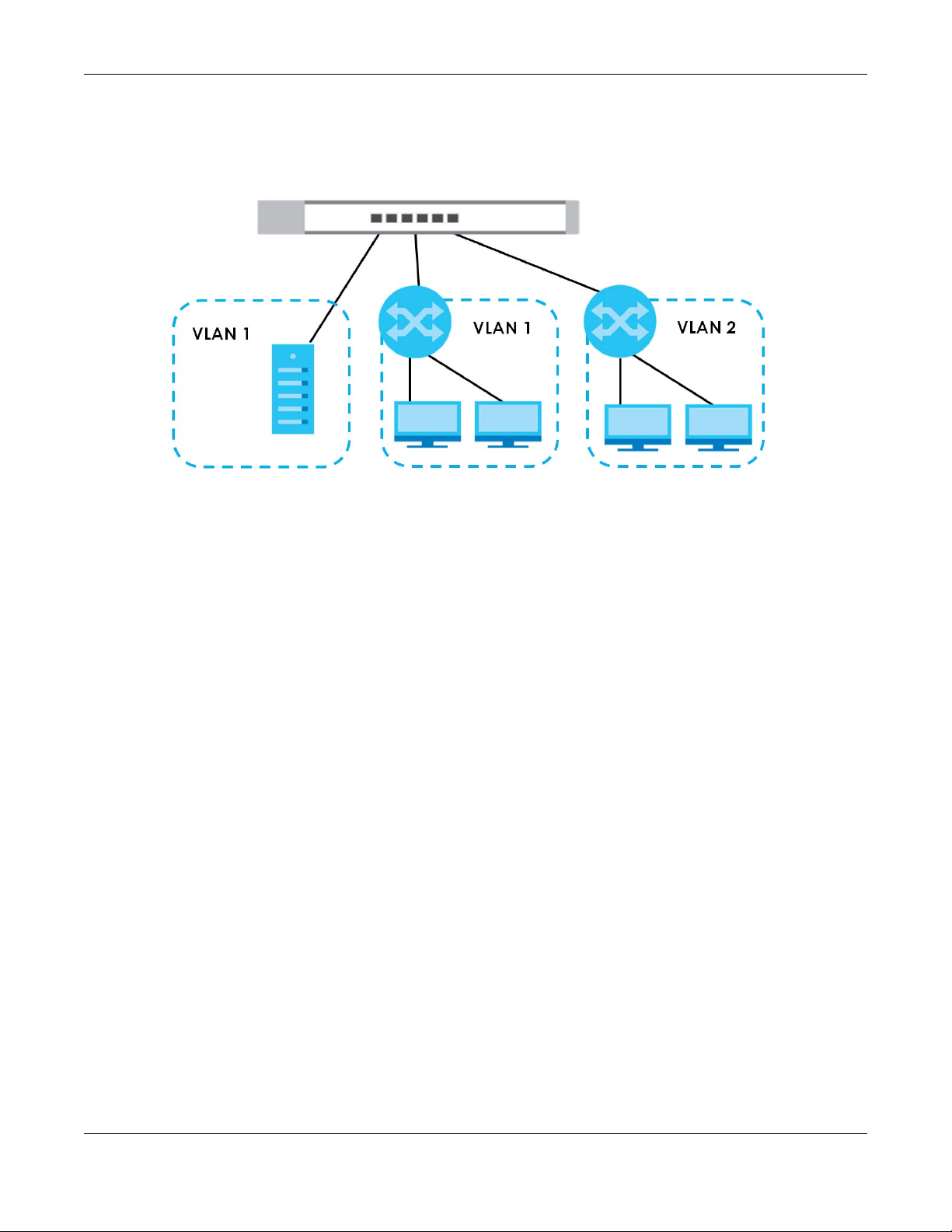
Chapter 1 Getting to Know Your Switch
Shared resources such as a server can be used by all ports in the same VLAN as the server. In the
following figure only ports that need access to the server need to be part of VLAN1. Ports can belong to
other VLAN groups too.
Figure 2 Shared Server Using VLAN Example
1.3 Ways to Manage the Switch
Use any of the following methods to manage the Switch.
• Web Configurator. This allows easy Switch setup and management using a (supported) web browser.
See Chapter 4 on page 16.
1.4 Good Habits for Managing the Switch
Do the following things regularly to make the Switch more secure and to manage the Switch more
effectively.
• Change the password. Use a password that’s not easy to guess and that consists of different types of
characters, such as numbers and letters.
• Write down the password and put it in a safe place.
• Back up the configuration (and make sure you know how to restore it). Restoring an earlier working
configuration may be useful if the device becomes unstable or even crashes. If you forget your
password, you will have to reset the Switch to its factory default settings. If you backed up an earlier
configuration file, you would not have to totally re-configure the Switch. You could simply restore your
last configuration.
GS1200 Series User’s Guide
11

Hardware Installation
2.1 Installation Scenarios
This chapter shows you how to install and connect the Switch.
The Switch can be placed on a desktop. Use the rubber feet in a desktop installation.
2.2 Desktop Installation Procedure
1 Make sure the Switch is clean and dry.
2 Set the Switch on a smooth, level surface strong enough to support the weight of the Switch and the
connected cables. Make sure there is a power outlet nearby.
CHAPTER 2
3 Make sure there is enough clearance around the Switch to allow air circulation and the attachment of
cables and the power cord.
Note: Make sure you are using the correct type of Ethernet cable (Category 5e, 6UTP/STP, or
better Ethernet cable).
GS1200 Series User’s Guide
12
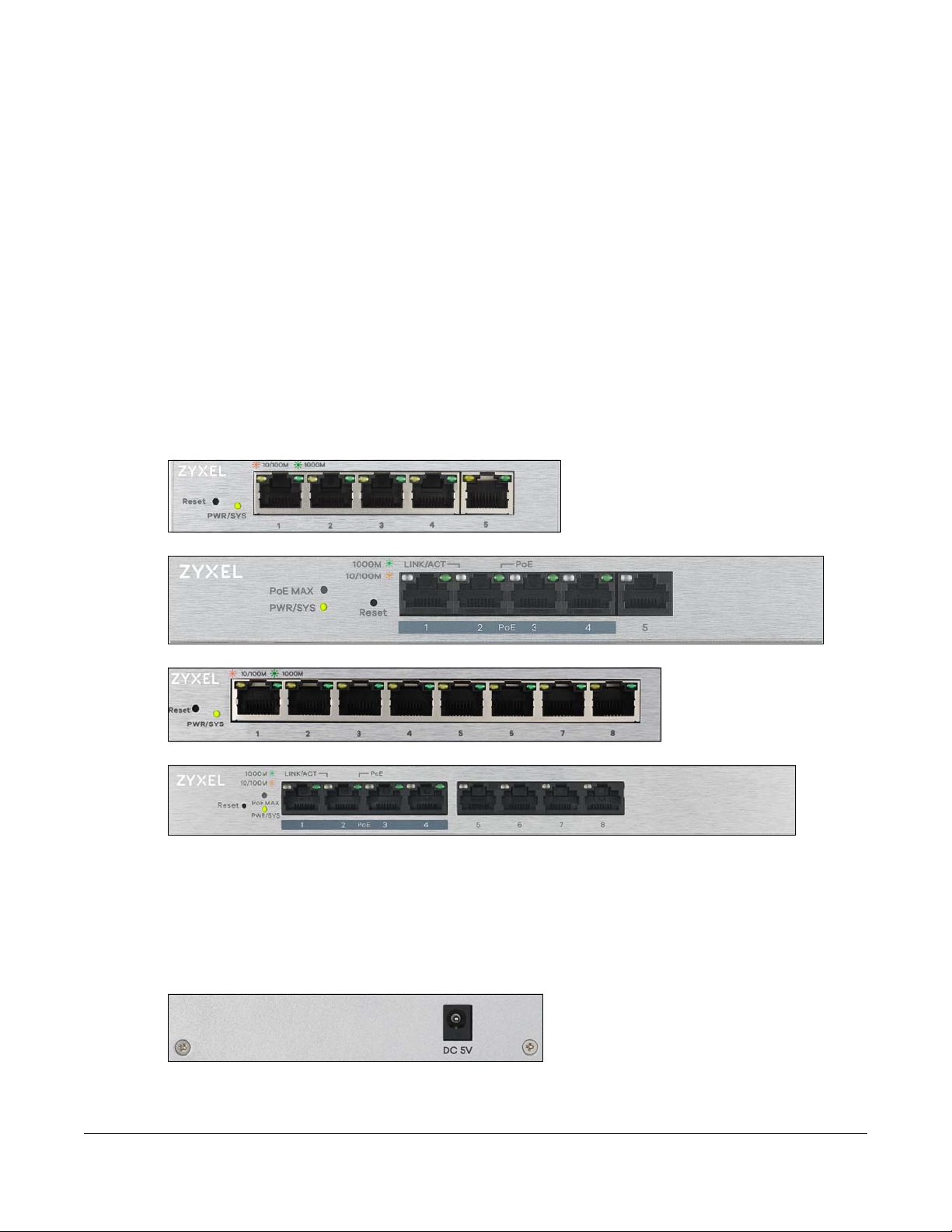
This chapter describes the front panel and rear panel of the Switch and shows you how to make the
hardware connections.
3.1 Front Panel
The following figures show the front panels of the Switch.
Figure 3 Front Panel: GS1200-5
Figure 4 Front Panel: GS1200-5HP v2
CHAPTER 3
Hardware Panels
Figure 5 Front Panel: GS1200-8
Figure 6 Front Panel: GS1200-8HP v2
3.2 Rear Panel
The following figures show the rear panels of the Switch.
Figure 7 Rear Panel: GS1200-5
GS1200 Series User’s Guide
13
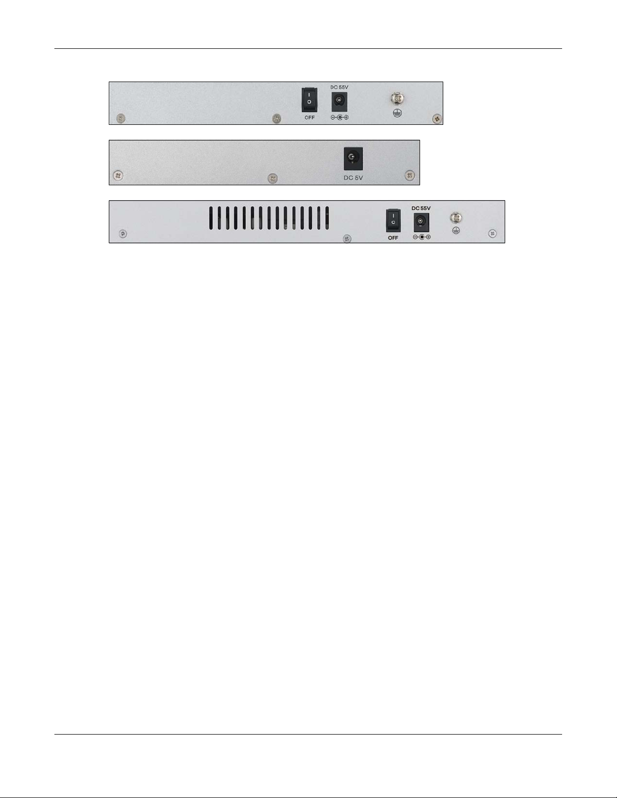
Figure 8 Rear Panel: GS1200-5HP v2
Figure 9 Rear Panel: GS1200-8
Figure 10 Rear Panel: GS1200-8HP v2
3.2.1 Power Connector
Note: Make sure you are using the correct power source as shown on the panel.
To connect power to the Switch, insert the female end of the power cord to the AC power receptacle
on the rear panel. Connect the other end of the supplied power cord to a power outlet. Make sure that
no objects obstruct the airflow.
Chapter 3 Hardware Panels
GS1200 Series User’s Guide
14

3.3 LEDs
After you connect the power to the Switch, view the LEDs to ensure proper functioning of the Switch
and as an aid in troubleshooting.
Table 2 LED Descriptions
LED COLOR STATUS DESCRIPTION
PWR/SYS Green On The system power is on.
LINK/ACT Amber (10/100
PoE
(GS1200-5HP
v2 & GS12008HP v2)
PoE Max
(GS1200-5HP
v2 & GS12008HP v2)
Chapter 3 Hardware Panels
Blinking The system is starting up.
Off The system power is off.
Mbps)
Green (1000
Mbps)
Green On PoE is enabled and power is supplied to the connected PoE-
Amber On More than 50W has been supplied to the PoE-enabled devices,
On The port has a successful 10/100 Mbps or 1000 Mbps connection.
Blinking The system is transmitting data through the port.
Blinking
once a
second
Off The port is disconnected or disabled.
Off PoE is disabled or power is not being supplied.
Off Less than 50W has been supplied to the PoE-enabled devices.
If you enable Loop Detection in the Port screen, the port in a loop
state will blink fast.
If you enable Loop Prevention in the Port screen, all ports will blink
fast. Later, the port in a loop state will be off. If a loop happens
on two ports, all ports will blink fast. Later, the higher-numbered
port will be off.
If you enable Loop Prevention in the Port screen, and a loop
happens on two ports, the higher-numbered port will be off.
enabled device.
and the PoE power output is approaching the power budget.
GS1200 Series User’s Guide
15

4.1 Overview
This section introduces the configuration and functions of the web configurator.
The web configurator is an HTML-based management interface that allows easy Switch setup and
management via Internet browser. Use Internet Explorer 10.0 and later versions, Mozilla Firefox 46.0.1 and
later versions, or Google Chrome 50.0 and later versions. The recommended screen resolution is 1024 by
768 pixels.
In order to use the web configurator you need to allow:
• Web browser pop-up windows from your device.
• JavaScript (enabled by default).
• Java permissions (enabled by default).
CHAPTER 4
The Web Configurator
4.2 System Login
1 Start your web browser.
2 Type “http://” and the IP address of the Switch (for example, the default management IP address is
192.168.1.3) in the Location or Address field. Press [ENTER]. Your computer must be in the same subnet in
order to access this website address.
3 The login screen appears. The default password is 1234.
Figure 11 Web Configurator: Login
4 The following screen displays if you log into the Switch for the first time. Enter a new password, retype it to
confirm and click Apply to view the first web configurator screen. Note that you can enter the default
password 1234 again, if you don’t want to change your password.
GS1200 Series User’s Guide
16

Chapter 4 The Web Configurator
Figure 12 Web Configurator: Login
4.3 The Web Configurator Layout
The System screen is the first screen that displays when you access the web configurator.
This guide uses GS1200-5HP v2 screens as an example. The screens may vary slightly for different models.
The following figure shows the navigating components of a web configurator screen.
GS1200 Series User’s Guide
17
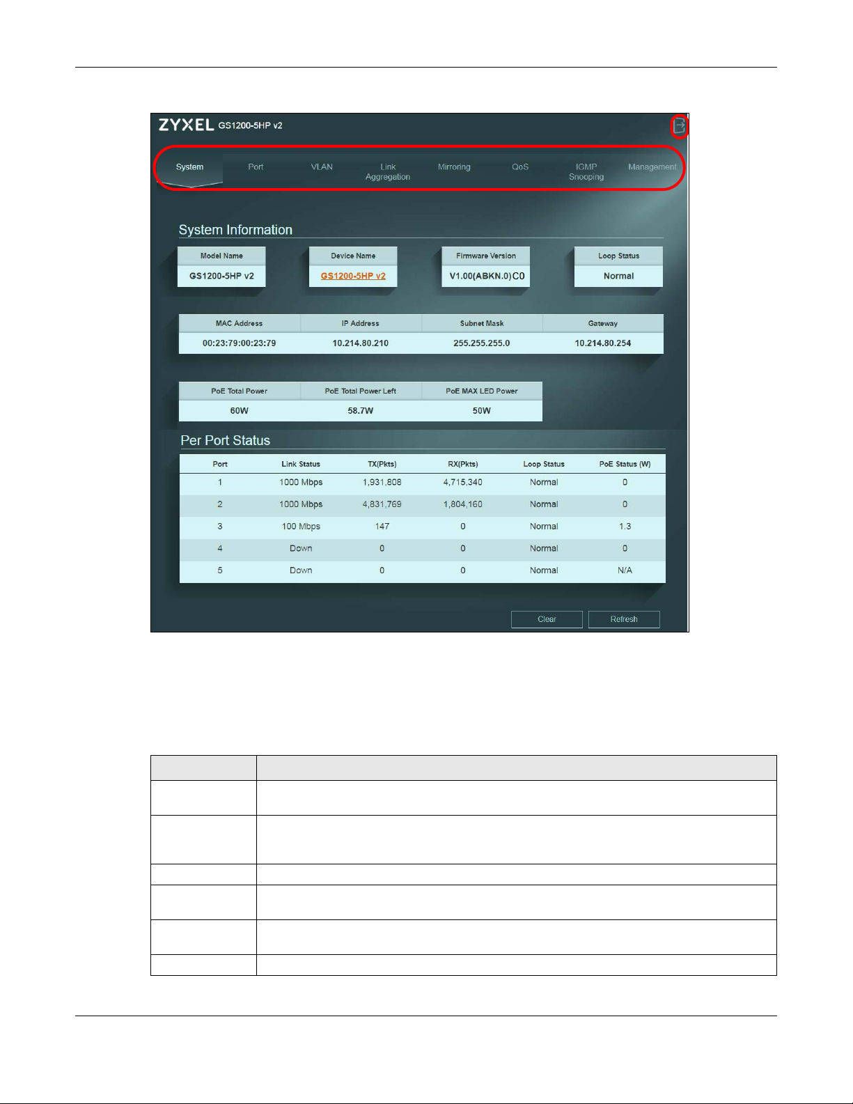
Chapter 4 The Web Configurator
Figure 13 Web Configurator Layout
A — Click the menu items to open the screen in the main window.
B — Click this link to log out of the web configurator.
The following table describes the links in the navigation panel.
Table 3 Navigation Panel Links
LINK DESCRIPTION
System This link takes you to a screen that displays general system information, PoE status, and
individual port statistics.
Port This link takes you to a screen to enable Broadcast Storm Control and Loop Prevention/Loop
Detection. You can also configure advanced settings, such as transmission speed, flow control,
and PoE on a port.
VLAN This link takes you to a screen where you can configure VLAN settings.
Link Aggregation This link takes you to screens where you can logically aggregate physical links to form one
logical and higher-bandwidth link.
Mirroring This link takes you to a screen where you can copy traffic from one port or ports to another port
so that you can examine the traffic from the first port without interference.
QoS This link takes you to a screen where you can configure port-based or IEEE 802.1p QoS.
GS1200 Series User’s Guide
18
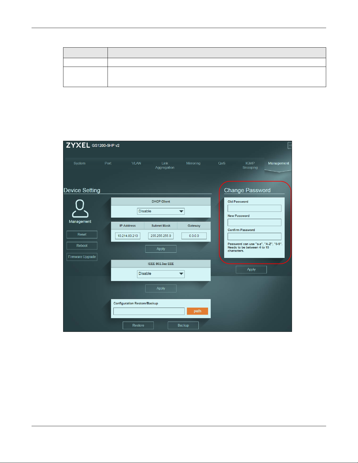
Chapter 4 The Web Configurator
Table 3 Navigation Panel Links (continued)
LINK DESCRIPTION
IGMP Snooping This link takes you to a screen where you can configure IGMP snooping.
Management This link takes you to screens where you can change the system login password, perform
firmware upgrade and configuration file maintenance as well as reboot the system. You can
also configure the IP address and subnet mask.
4.3.1 Change Your Password
After you log in for the first time, it is recommended you change the default administrator password.
Click Management to display the next screen to change your login password.
Figure 14 Change Administrator Login Password
4.4 Switch Lockout
You could block yourself (and all others) from managing the Switch if you do one of the following:
1 Remove all ports from VLAN1 and you do not configure other VLAN groups.
2 Forget the password and/or IP address.
GS1200 Series User’s Guide
19

Chapter 4 The Web Configurator
3 You forgot to log out of the Switch from a computer before logging in again on another computer.
Note: Be careful not to lock yourself and others out of the Switch.
4.5 Resetting the Switch
If you forget the administrator password or cannot access the Web Configurator, you will need to use
the Reset button at the front panel of the device to reset the Switch back to the factory defaults.
This means that you will lose all configurations that you had previously and the password will be reset to
“1234”. IP address will also be reset to 192.168.1.3
1 Make sure the PWR/SYS LED is on (not blinking).
2 To set the device back to the factory default settings, press the Reset button for ten seconds or until the
PWR/SYS LED begins to blink and then release it. When the PWR/SYS LED begins to blink, the defaults
have been restored and the device restarts.
4.6 Logging Out of the Web Configurator
Click the Logout icon in a screen to exit the web configurator. You have to log in with your password
again after you log out. This is recommended after you finish a management session for security reasons.
GS1200 Series User’s Guide
20
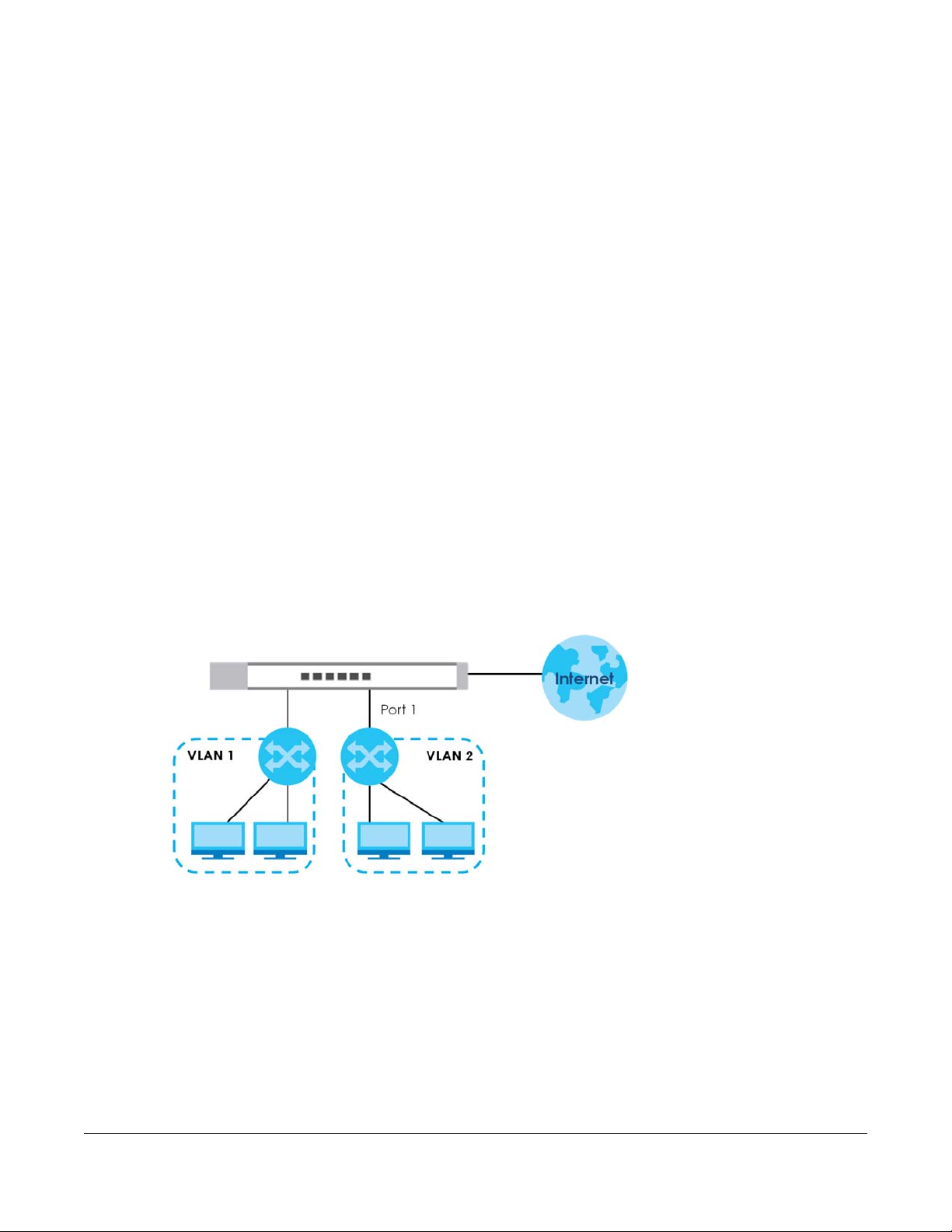
Initial Setup Example
5.1 Overview
This chapter shows how to set up the Switch for an example network.
The following lists the configuration steps for the initial setup:
• Creating a VLAN
• Setting Port VID
• Power over Ethernet (PoE) Configuration
5.1.1 Creating a VLAN
VLANs confine broadcast frames to the VLAN group in which the port(s) belongs. You can create a
VLAN group with fixed port members to do this.
CHAPTER 5
In this example, you want to configure port 1 as a member of VLAN 2.
Figure 15 Initial Setup Network Example: VLAN
1 Click VLAN in the navigation panel and click the Create New VLAN button.
GS1200 Series User’s Guide
21
Loading…
Zyxel GS1200-8
Smart коммутатор Zyxel GS1200-8, 8xGE, настольный, бесшумный, с поддержкой VLAN, IGMP, QoS и Link Aggregation
Купить по низким ценам Zyxel GS1200-8
Описание Zyxel GS1200-8
Основные характеристики
-
Тип коммутатора — Управляемый (Layer 2)
-
Технология доступа — Ethernet
-
Тип разъемов — RJ-45
-
Тип кабеля — Витая пара
-
Количество LAN портов — 8 шт
-
Тип LAN портов — 10/100/1000 Base-TX (1000 мбит/с)
-
Протоколы Ethernet — IEEE 802.3a, IEEE 802.3ab, IEEE 802.3u
-
Внутренняя пропускная способность — 16 ГБит/с
-
Размер таблицы MAC-адресов — 2000
-
Поддержка IPv6 — Нет
-
Поддержка 3G/4G модемов — Нет
-
Поддержка Auto-MDI/MDI-X — Есть
-
Поддержка IEEE 802.1p (Priority tags) — Есть
-
Поддержка IEEE 802.1q (VLAN) — Есть
-
Поддержка IEEE 802.3x (Flow control) — Есть
-
Поддержка PoE — Нет
-
Поддержка PoE+ — Нет
-
Зеркалирование портов — Есть
-
Поддержка работы в стеке — Нет
Управление
-
Web-интерфейс — Есть
-
DHCP-клиент — Есть
-
Поддержка IGMP (Multicast) — Есть
Эксплуатационные характеристики
-
Рабочая температура — от 0 до +40°С
-
Температура хранения — от -40 до +70°С
-
Влажность при эксплуатации — от 10 до 90%(без конденсации)
-
Влажность при хранении — от 10 до 90%(без конденсации)
Источник питания
-
Тип питания — От электросети
-
Напряжение — 230 В
-
Ток — 1 А
-
Потребляемая мощность — 4.37 Вт
Поддержка операционных систем
-
Поддержка операционных систем — MacOS, UNIX or Linux, Windows 98/NT/2000/XP/Vista/7/8
Монтаж
-
Возможность установки в стойку — Нет
Дополнительные характеристики
-
Материал корпуса — Металл
-
Цвет — Серый
Технические характеристики Zyxel GS1200-8
-
Ширина упаковки
10 см -
Высота упаковки
10 см -
Глубина упаковки
10 см -
Объемный вес
1 кг -
Единица измерения
шт. -
Кратность поставки
1
-
Тип устройства
Управляемые
-
Тип сети
Сетевой
-
Скорость передачи
10 100 1000
-
Поддержка POE
Нет
-
Уровень
L2
-
Ширина упаковки
10 см -
Высота упаковки
10 см -
Глубина упаковки
10 см -
Объемный вес
1 кг -
Единица измерения
шт. -
Кратность поставки
1 -
Тип устройства
Управляемые
-
Тип сети
Сетевой
-
Скорость передачи
10 100 1000
-
Поддержка POE
Нет
-
Уровень
L2
Заказ в один клик
Мы позвоним Вам в ближайшее время
Несоответствие минимальной сумме заказ
Минимальная сумма заказа 1 500,00 ₽
Просьба увеличить заказ.
Зубцов Алексей Владимирович
0
0
Достоинства
хорошее качество
Недостатки
нет
Комментарий
Поддержка гигабитного интернета во всех 8 портах. Удобная и понятная настройка через web. Full duplex. Производительность в 16 Gbps. Увеличенный буфер до 192 кб. Неплохое бюджетное устройство для ленивых. Настройка проста, особых знаний не требуется.
Рафаэль Гамбоа
0
0
Достоинства
Отличный продукт, переключатель отличного качества
Недостатки
На данный момент нет
Комментарий
Отличный вариант за свою цену!
Гарантия производителя 1 год
Корпорация ZyXEL Communications с 1990 года, со времени своей разработки первого модема, продолжает специализироваться на решениях к доступу в Интернет. В данный момент операторское и абонентское оборудование имеет приоритетное направление в развитии бизнеса компании, широкополосный доступ с технологией xDLS, LTE, PON и Metro Ethermet, беспроводные профессиональные сети и системы сетевой безопасности.
Срочная доставка день в день
Объемный вес: 1 кг
Габариты: 10x10x10
* только для города Москва
Самовывоз по РФ
Объемный вес: 1 кг
Габариты: 10x10x10
Доставка курьером по РФ
Объемный вес: 1 кг
Габариты: 10x10x10
| Собственная служба доставки | 490 ₽ | 2-3 дней | |
|
|
|||
| Почта России | уточнять | 3-20 дней | |
|
|
|||
| ПЭК | уточнять | 2-7 дней | |
|
|
|||
| СДЭК | Экспресс лайт | уточнять | 2-7 дней |
|
|
|||
| СДЭК | Супер Экспресс | уточнять | 2-4 дней |
|
|
|||
| Деловые Линии | уточнять | 2-7 дней | |
|
|
|||
| Pony Express | уточнять | 2-7 дней | |
|
|
|||
| DPD | уточнять | 2-7 дней | |
|
|
|||
| DHL | уточнять | 2-7 дней | |
|
|
|||
| Boxberry | уточнять | 2-7 дней | |
|
|
|||
| ЖелДорЭкспедиция | уточнять | 3-10 дней | |
|
|
|||
| Байкал Сервис | уточнять | 2-10 дней | |
|
|
|||
| Энергия | 400,00 ₽ | 2-7 дней |


Zyxel Smart коммутатор 8xGE, настольный, бесшумный, с поддержкой VLAN, GS1200-8
Артикул: GS1200-8-EU0101F
Smart коммутатор Zyxel GS1200-8, 8xGE, настольный, бесшумный, с поддержкой VLAN, IGMP, QoS и Link Aggregation
Объемный вес: 1 кг
Габариты:
10x10x10
В наличии
Ожидается поступление, уточнить
5 909,09 ₽
Скидка 34%
3 900,00 ₽
Цена за 1 шт.
Описание Zyxel GS1200-8-EU0101F
Zyxel GS1200-8-EU0101F – 8-портовый гигабитный коммутатор с Web-управлением, настольного исполнения, бесшумный, с поддержкой VLAN, IGMP, QoS и Link Aggregation.
Удобное управление с помощью web-технологий
Интерфейс настройки коммутатора выдает пользователю пошаговые инструкции по настройке параметров, конфигурированию и управлению, включая создание резервной копии конфигурационного файла и обновление микрокода. Применяя этот интерфейс, пользователь может легко и быстро несколькими щелчками мышью полностью подготовить сеть к работе, после чего заняться своим основным бизнесом.

IGMP Snooping для оптимизации доставки трафика
Используют сообщения с запросами и отчетами протокола IGMP (Internet Group Management Protocol), коммутатор перенаправляет пакеты только на те порты, которые запросили трафик multicast. Эта функция помогает оптимизировать производительность коммутатора при обработке трафика multicast и особенно полезна для приложений IP multicast, интенсивно использующих полосу пропускания, например, онлайновой трансляции видео и игр.
Разделение локальной сети на VLAN для улучшения безопасности
Функция VLAN (virtual local area network) позволяет разделить трафик, передаваемый по локальной сети компании, например, изолировать трафик сетевых администраторов от трафика остальных пользователей, либо трафик сотрудников компании от трафика ее гостей.
Усовершенствованная QoS на уровне портов для более эффективного контроля трафика
Функция QoS (Quality of service) назначает разные приоритеты приложениям, пользователям или потокам видео/аудио/голоса либо гарантирует заданный уровень производительности для определенных потоков данных.
Link Aggregation обеспечивает скорость выше скорости одного соединения
В коммутаторах GS1200-5/8 предусмотрена возможность объединения пропускной способности двух физических портов для организации высокоскоростного канала передачи данных, который сокращает время передачи больших данных и улучшает надежность соединения.
Расширенные функции экономии энергии
Используемая в коммутаторе функция IEEE 802.3az Energy Efficient Ethernet (EEE) автоматически определяет интенсивность сетевого трафика и в зависимости от нее динамически уменьшает потребляемую устройством мощность для экономии электроэнергии в те часы, когда по сети передается мало трафика.

Нет вентилятора – бесшумная работа
Вам не придется жертвовать тишиной в вашем офисе ради улучшения контроля и видимости вашей локальной сети. В этом коммутаторе бизнес-класса нет вентилятора, поэтому он работает бесшумно и у него меньше компонентов, сбой которых приводит к выходу из строя всего устройства.

Поддержка различных умных функций коммутатора
В этом коммутаторе используется Gigabit Ethernet, работающий в 10 раз быстрее, чем Fast Ethernet. Коммутатор обеспечивает выделенную неблокирующую полосу пропускания до 2000 Mbps на один порт и поддерживает различные расширенные функции, например, зеркалирование портов, пакеты Jumbo Frame, broadcast storm control и обнаружение/предотвращение образования петель. Он великолепно подходит компании SMB, которой нужно обеспечить высокую производительность своих сетевых приложений!
Компактный прочный металлический корпус, который можно закрепить на стене

Нет внутреннего вентилятора

Металлический корпус

Опция монтажа на стене
Схема применения

Технические характеристики Zyxel GS1200-8-EU0101F
- Модель: GS1200-8-EU0101F
- Тип: 8-портовый гигабитный коммутатор с Web-управлением
- Корпус: Металлический
- Auto MDI/MDI-X: Да
- Store and Forward: Да
- Поддержка Full Duplex: Да
- Flow Control: Да
- Порты 10/100 Mbps Ethernet: —
- Порты 10/100/1000 Mbps Ethernet: 8
- Порты 10/100/1000 Mbps Ethernet PoE+: —
- Производительность коммутации: 16 Gbps
- MAC-адресов: 4 тыс.
- Буфер пакетов: 192 KB
- Размер пакетов Jumbo Frame: Up to 9 KB
- Web GUI: Да
- 802.3x Flow Control: Да
- Клиент DHCP
- Да: Да: Да: Да
- 802.1Q VLAN: Да
- WRR Priority QoS: Да
- QoS на уровне портов: Да
- 802.1p CoS: Да
- Broadcast Storm Control: Да
- Обнаружение / предотвращение образования петель: Да
- Совместимость с IGMP Snooping v1, v2 и v3: Да
- Link Aggregation: Да
- Зеркалирование портов: Да
- Нет вентилятора: Да
- Экономия энергия за счет определения состояния соединения и длины кабеля: Да
- Напряжение на входе: 5 В пост. тока / 1А
- Блок питания: Внешний
- Максимальное энергопотребление (Ватт): 4.37
- Бюджет питания PoE (Ватт): —
- Размеры без упаковки (WxDxH): 155x 85 x 26 мм
- Вес без упаковки: 325 г
- Размеры в упаковке (WxDxH): 161 x 90 x 95 мм
- Вес в упаковке: 497 г
Требования к окружающей среде
- Рабочая: температура: 0°C — 40°C
- Рабочая влажность: 10% — 90% (без выпадения конденсата)
- Температура хранения: -40°C — 70°C
- Влажность хранения: 10% — 90% (без выпадения конденсата)